epmotion® 5075 - operating manual - eppendorf · diluting series. a defined volume is transported...
TRANSCRIPT

Operating manual — epMotion® 5075seeon p.Fig.Tab.p.Operating manual
epMotion® 5075Operating manual
5075 900.157

5075 900.157-13/0411
Copyright© 2008 Eppendorf AG, Hamburg. No part of this publication may be reproduced without the prior permission of the copyright owner.
Trademarks
epMotion®, epT.I.P.S.®, eppendorf® and Mastercycler® are registered trademarks of Eppendorf AG, Hamburg, Germany.
Falcon is a registered trademark of Becton Dickinson, Franklin Lakes, USA.
LightCycler® is a registered trademark of Roche Diagnostics.
Registered trademarks are not marked in all cases with ™ or ® in this manual.

epMotion® 5075 — Operating manual
1
Table of contents
1 Table of contents
Table of contents
1 User instructions . . . . . . . . . . . . . . . . . . . . . . . . . . . . . . . . . . . . . . . . . . . . . . . . . . . . . . . . . . . . . . . . . . . . . . . . . . . . 7
1.1 Using this manual . . . . . . . . . . . . . . . . . . . . . . . . . . . . . . . . . . . . . . . . . . . . . . . . . . . . . . . . . . . . . . . . . . . . . . . 71.2 Danger symbols and danger levels . . . . . . . . . . . . . . . . . . . . . . . . . . . . . . . . . . . . . . . . . . . . . . . . . . . . . . . . . 71.3 Symbols used . . . . . . . . . . . . . . . . . . . . . . . . . . . . . . . . . . . . . . . . . . . . . . . . . . . . . . . . . . . . . . . . . . . . . . . . . . 81.4 Abbreviations used . . . . . . . . . . . . . . . . . . . . . . . . . . . . . . . . . . . . . . . . . . . . . . . . . . . . . . . . . . . . . . . . . . . . . . 81.5 Glossary . . . . . . . . . . . . . . . . . . . . . . . . . . . . . . . . . . . . . . . . . . . . . . . . . . . . . . . . . . . . . . . . . . . . . . . . . . . . . . 8
2 Product description . . . . . . . . . . . . . . . . . . . . . . . . . . . . . . . . . . . . . . . . . . . . . . . . . . . . . . . . . . . . . . . . . . . . . . . . . 11
2.1 Main illustration. . . . . . . . . . . . . . . . . . . . . . . . . . . . . . . . . . . . . . . . . . . . . . . . . . . . . . . . . . . . . . . . . . . . . . . . 112.2 Delivery package . . . . . . . . . . . . . . . . . . . . . . . . . . . . . . . . . . . . . . . . . . . . . . . . . . . . . . . . . . . . . . . . . . . . . . 122.3 Features . . . . . . . . . . . . . . . . . . . . . . . . . . . . . . . . . . . . . . . . . . . . . . . . . . . . . . . . . . . . . . . . . . . . . . . . . . . . . 13
2.3.1 Principle of operation . . . . . . . . . . . . . . . . . . . . . . . . . . . . . . . . . . . . . . . . . . . . . . . . . . . . . . . . . . . . 132.4 Overview of hardware and labware . . . . . . . . . . . . . . . . . . . . . . . . . . . . . . . . . . . . . . . . . . . . . . . . . . . . . . . . 14
2.4.1 Hardware. . . . . . . . . . . . . . . . . . . . . . . . . . . . . . . . . . . . . . . . . . . . . . . . . . . . . . . . . . . . . . . . . . . . . . 142.4.2 Labware . . . . . . . . . . . . . . . . . . . . . . . . . . . . . . . . . . . . . . . . . . . . . . . . . . . . . . . . . . . . . . . . . . . . . . 212.4.3 Important volume terms for tubes and wells . . . . . . . . . . . . . . . . . . . . . . . . . . . . . . . . . . . . . . . . . . . 24
3 Safety . . . . . . . . . . . . . . . . . . . . . . . . . . . . . . . . . . . . . . . . . . . . . . . . . . . . . . . . . . . . . . . . . . . . . . . . . . . . . . . . . . . . 29
3.1 Intended use. . . . . . . . . . . . . . . . . . . . . . . . . . . . . . . . . . . . . . . . . . . . . . . . . . . . . . . . . . . . . . . . . . . . . . . . . . 293.2 Information on product liability . . . . . . . . . . . . . . . . . . . . . . . . . . . . . . . . . . . . . . . . . . . . . . . . . . . . . . . . . . . . 293.3 Warnings for intended use . . . . . . . . . . . . . . . . . . . . . . . . . . . . . . . . . . . . . . . . . . . . . . . . . . . . . . . . . . . . . . . 293.4 Safety devices . . . . . . . . . . . . . . . . . . . . . . . . . . . . . . . . . . . . . . . . . . . . . . . . . . . . . . . . . . . . . . . . . . . . . . . . 32
4 Installation . . . . . . . . . . . . . . . . . . . . . . . . . . . . . . . . . . . . . . . . . . . . . . . . . . . . . . . . . . . . . . . . . . . . . . . . . . . . . . . . 33
5 Operation . . . . . . . . . . . . . . . . . . . . . . . . . . . . . . . . . . . . . . . . . . . . . . . . . . . . . . . . . . . . . . . . . . . . . . . . . . . . . . . . . 34
5.1 First steps . . . . . . . . . . . . . . . . . . . . . . . . . . . . . . . . . . . . . . . . . . . . . . . . . . . . . . . . . . . . . . . . . . . . . . . . . . . . 345.1.1 Check correct installation . . . . . . . . . . . . . . . . . . . . . . . . . . . . . . . . . . . . . . . . . . . . . . . . . . . . . . . . . 345.1.2 Switch on the epMotion 5075 and log in as the user . . . . . . . . . . . . . . . . . . . . . . . . . . . . . . . . . . . . 34
5.2 Overview of operation with the control panel . . . . . . . . . . . . . . . . . . . . . . . . . . . . . . . . . . . . . . . . . . . . . . . . . 365.2.1 Menu structure . . . . . . . . . . . . . . . . . . . . . . . . . . . . . . . . . . . . . . . . . . . . . . . . . . . . . . . . . . . . . . . . . 365.2.2 Main navigation . . . . . . . . . . . . . . . . . . . . . . . . . . . . . . . . . . . . . . . . . . . . . . . . . . . . . . . . . . . . . . . . . 375.2.3 Navigating in the navigation tree . . . . . . . . . . . . . . . . . . . . . . . . . . . . . . . . . . . . . . . . . . . . . . . . . . . . 375.2.4 Keys on the control panel . . . . . . . . . . . . . . . . . . . . . . . . . . . . . . . . . . . . . . . . . . . . . . . . . . . . . . . . . 38
5.3 Overview of Operating Sequence. . . . . . . . . . . . . . . . . . . . . . . . . . . . . . . . . . . . . . . . . . . . . . . . . . . . . . . . . . 405.4 Placing labware on the worktable . . . . . . . . . . . . . . . . . . . . . . . . . . . . . . . . . . . . . . . . . . . . . . . . . . . . . . . . . . 41
5.4.1 Placing the gripper and gripper holder . . . . . . . . . . . . . . . . . . . . . . . . . . . . . . . . . . . . . . . . . . . . . . . 415.4.2 Manually filling the vacuum unit (epMotion 5075 VAC) . . . . . . . . . . . . . . . . . . . . . . . . . . . . . . . . . . . 425.4.3 Position labware . . . . . . . . . . . . . . . . . . . . . . . . . . . . . . . . . . . . . . . . . . . . . . . . . . . . . . . . . . . . . . . . 43
5.5 Create and start methods . . . . . . . . . . . . . . . . . . . . . . . . . . . . . . . . . . . . . . . . . . . . . . . . . . . . . . . . . . . . . . . . 435.5.1 Create new folder in user directory . . . . . . . . . . . . . . . . . . . . . . . . . . . . . . . . . . . . . . . . . . . . . . . . . . 435.5.2 Create and save methods . . . . . . . . . . . . . . . . . . . . . . . . . . . . . . . . . . . . . . . . . . . . . . . . . . . . . . . . . 445.5.3 Load worktable . . . . . . . . . . . . . . . . . . . . . . . . . . . . . . . . . . . . . . . . . . . . . . . . . . . . . . . . . . . . . . . . . 455.5.4 Defining the procedure . . . . . . . . . . . . . . . . . . . . . . . . . . . . . . . . . . . . . . . . . . . . . . . . . . . . . . . . . . . 485.5.5 Check method (parameter test) . . . . . . . . . . . . . . . . . . . . . . . . . . . . . . . . . . . . . . . . . . . . . . . . . . . . 595.5.6 Copy predefined methods into user directory . . . . . . . . . . . . . . . . . . . . . . . . . . . . . . . . . . . . . . . . . . 605.5.7 Activate and deactivate Optical Sensor. . . . . . . . . . . . . . . . . . . . . . . . . . . . . . . . . . . . . . . . . . . . . . . 605.5.8 Starting the method. . . . . . . . . . . . . . . . . . . . . . . . . . . . . . . . . . . . . . . . . . . . . . . . . . . . . . . . . . . . . . 615.5.9 Observations, method run. . . . . . . . . . . . . . . . . . . . . . . . . . . . . . . . . . . . . . . . . . . . . . . . . . . . . . . . . 62
3

epMotion® 5075 — Operating manual
4
1
Tabl
e of
con
tent
s
5.6 Stop or interrupt methods . . . . . . . . . . . . . . . . . . . . . . . . . . . . . . . . . . . . . . . . . . . . . . . . . . . . . . . . . . . . . . . . 635.6.1 Stop method prematurely . . . . . . . . . . . . . . . . . . . . . . . . . . . . . . . . . . . . . . . . . . . . . . . . . . . . . . . . . 635.6.2 Service commands after a method is stopped . . . . . . . . . . . . . . . . . . . . . . . . . . . . . . . . . . . . . . . . . 635.6.3 Continue method. . . . . . . . . . . . . . . . . . . . . . . . . . . . . . . . . . . . . . . . . . . . . . . . . . . . . . . . . . . . . . . . 655.6.4 Abort method . . . . . . . . . . . . . . . . . . . . . . . . . . . . . . . . . . . . . . . . . . . . . . . . . . . . . . . . . . . . . . . . . . 65
5.7 epMotion 5075 Shut Down and Switch Off . . . . . . . . . . . . . . . . . . . . . . . . . . . . . . . . . . . . . . . . . . . . . . . . . . . 65
6 Quick Start . . . . . . . . . . . . . . . . . . . . . . . . . . . . . . . . . . . . . . . . . . . . . . . . . . . . . . . . . . . . . . . . . . . . . . . . . . . . . . . . 66
6.1 Short instructions . . . . . . . . . . . . . . . . . . . . . . . . . . . . . . . . . . . . . . . . . . . . . . . . . . . . . . . . . . . . . . . . . . . . . . 666.1.1 Select the method and start . . . . . . . . . . . . . . . . . . . . . . . . . . . . . . . . . . . . . . . . . . . . . . . . . . . . . . . 666.1.2 Typical operating sequence . . . . . . . . . . . . . . . . . . . . . . . . . . . . . . . . . . . . . . . . . . . . . . . . . . . . . . . 67
6.2 Example method. . . . . . . . . . . . . . . . . . . . . . . . . . . . . . . . . . . . . . . . . . . . . . . . . . . . . . . . . . . . . . . . . . . . . . . 716.2.1 Method objective . . . . . . . . . . . . . . . . . . . . . . . . . . . . . . . . . . . . . . . . . . . . . . . . . . . . . . . . . . . . . . . . 716.2.2 Sample preparation. . . . . . . . . . . . . . . . . . . . . . . . . . . . . . . . . . . . . . . . . . . . . . . . . . . . . . . . . . . . . . 716.2.3 Method sequence . . . . . . . . . . . . . . . . . . . . . . . . . . . . . . . . . . . . . . . . . . . . . . . . . . . . . . . . . . . . . . . 726.2.4 Start method . . . . . . . . . . . . . . . . . . . . . . . . . . . . . . . . . . . . . . . . . . . . . . . . . . . . . . . . . . . . . . . . . . . 75
7 Troubleshooting. . . . . . . . . . . . . . . . . . . . . . . . . . . . . . . . . . . . . . . . . . . . . . . . . . . . . . . . . . . . . . . . . . . . . . . . . . . . 76
7.1 Error search . . . . . . . . . . . . . . . . . . . . . . . . . . . . . . . . . . . . . . . . . . . . . . . . . . . . . . . . . . . . . . . . . . . . . . . . . . 767.2 General errors . . . . . . . . . . . . . . . . . . . . . . . . . . . . . . . . . . . . . . . . . . . . . . . . . . . . . . . . . . . . . . . . . . . . . . . . 76
7.2.1 Read error of the optical sensor . . . . . . . . . . . . . . . . . . . . . . . . . . . . . . . . . . . . . . . . . . . . . . . . . . . . 767.2.2 Dispensing error . . . . . . . . . . . . . . . . . . . . . . . . . . . . . . . . . . . . . . . . . . . . . . . . . . . . . . . . . . . . . . . . 77
7.3 Error messages . . . . . . . . . . . . . . . . . . . . . . . . . . . . . . . . . . . . . . . . . . . . . . . . . . . . . . . . . . . . . . . . . . . . . . . 77
8 Maintenance . . . . . . . . . . . . . . . . . . . . . . . . . . . . . . . . . . . . . . . . . . . . . . . . . . . . . . . . . . . . . . . . . . . . . . . . . . . . . . 108
8.1 Service . . . . . . . . . . . . . . . . . . . . . . . . . . . . . . . . . . . . . . . . . . . . . . . . . . . . . . . . . . . . . . . . . . . . . . . . . . . . . 1088.1.1 Replacing the sealing rings of the eight-channel dispensing tool . . . . . . . . . . . . . . . . . . . . . . . . . . 1088.1.2 Replacing the seals of the vacuum unit . . . . . . . . . . . . . . . . . . . . . . . . . . . . . . . . . . . . . . . . . . . . . 1088.1.3 Replace the sealing mat of the Vac Lid. . . . . . . . . . . . . . . . . . . . . . . . . . . . . . . . . . . . . . . . . . . . . . 1088.1.4 Maintaining the dispensing tools . . . . . . . . . . . . . . . . . . . . . . . . . . . . . . . . . . . . . . . . . . . . . . . . . . . 1098.1.5 Maintaining the gripper . . . . . . . . . . . . . . . . . . . . . . . . . . . . . . . . . . . . . . . . . . . . . . . . . . . . . . . . . . 109
8.2 Cleaning . . . . . . . . . . . . . . . . . . . . . . . . . . . . . . . . . . . . . . . . . . . . . . . . . . . . . . . . . . . . . . . . . . . . . . . . . . . . 1098.2.1 Cleaning the worktable . . . . . . . . . . . . . . . . . . . . . . . . . . . . . . . . . . . . . . . . . . . . . . . . . . . . . . . . . . 1098.2.2 Cleaning the worktable base adapter . . . . . . . . . . . . . . . . . . . . . . . . . . . . . . . . . . . . . . . . . . . . . . . 1098.2.3 Cleaning the dispensing tools . . . . . . . . . . . . . . . . . . . . . . . . . . . . . . . . . . . . . . . . . . . . . . . . . . . . . 1098.2.4 Cleaning the gripper . . . . . . . . . . . . . . . . . . . . . . . . . . . . . . . . . . . . . . . . . . . . . . . . . . . . . . . . . . . . 1108.2.5 Cleaning the vacuum unit . . . . . . . . . . . . . . . . . . . . . . . . . . . . . . . . . . . . . . . . . . . . . . . . . . . . . . . . 1108.2.6 Cleaning the thermomixer . . . . . . . . . . . . . . . . . . . . . . . . . . . . . . . . . . . . . . . . . . . . . . . . . . . . . . . . 1108.2.7 Cleaning the control panel . . . . . . . . . . . . . . . . . . . . . . . . . . . . . . . . . . . . . . . . . . . . . . . . . . . . . . . 1108.2.8 Cleaning the thermoadapter, thermoblock and thermorack . . . . . . . . . . . . . . . . . . . . . . . . . . . . . . 1108.2.9 Cleaning the Vac Lid / Vac Thermo Lid . . . . . . . . . . . . . . . . . . . . . . . . . . . . . . . . . . . . . . . . . . . . . . 1108.2.10 Autoclave hardware and labware . . . . . . . . . . . . . . . . . . . . . . . . . . . . . . . . . . . . . . . . . . . . . . . . . . 110
8.3 Decontamination before shipment . . . . . . . . . . . . . . . . . . . . . . . . . . . . . . . . . . . . . . . . . . . . . . . . . . . . . . . . 111
9 Technical data . . . . . . . . . . . . . . . . . . . . . . . . . . . . . . . . . . . . . . . . . . . . . . . . . . . . . . . . . . . . . . . . . . . . . . . . . . . . 112
9.1 Power supply . . . . . . . . . . . . . . . . . . . . . . . . . . . . . . . . . . . . . . . . . . . . . . . . . . . . . . . . . . . . . . . . . . . . . . . . 1129.2 Ambient conditions . . . . . . . . . . . . . . . . . . . . . . . . . . . . . . . . . . . . . . . . . . . . . . . . . . . . . . . . . . . . . . . . . . . . 1129.3 Weight/dimensions . . . . . . . . . . . . . . . . . . . . . . . . . . . . . . . . . . . . . . . . . . . . . . . . . . . . . . . . . . . . . . . . . . . . 112
9.3.1 Dimensions . . . . . . . . . . . . . . . . . . . . . . . . . . . . . . . . . . . . . . . . . . . . . . . . . . . . . . . . . . . . . . . . . . . 1129.3.2 Weight . . . . . . . . . . . . . . . . . . . . . . . . . . . . . . . . . . . . . . . . . . . . . . . . . . . . . . . . . . . . . . . . . . . . . . . 112
9.4 Interfaces . . . . . . . . . . . . . . . . . . . . . . . . . . . . . . . . . . . . . . . . . . . . . . . . . . . . . . . . . . . . . . . . . . . . . . . . . . . 1139.5 Dispensing Tools . . . . . . . . . . . . . . . . . . . . . . . . . . . . . . . . . . . . . . . . . . . . . . . . . . . . . . . . . . . . . . . . . . . . . 113

epMotion® 5075 — Operating manual
1
Table of contents
9.6 Further specifications . . . . . . . . . . . . . . . . . . . . . . . . . . . . . . . . . . . . . . . . . . . . . . . . . . . . . . . . . . . . . . . . . . 1149.6.1 Noise level. . . . . . . . . . . . . . . . . . . . . . . . . . . . . . . . . . . . . . . . . . . . . . . . . . . . . . . . . . . . . . . . . . . . 1149.6.2 Optical sensor . . . . . . . . . . . . . . . . . . . . . . . . . . . . . . . . . . . . . . . . . . . . . . . . . . . . . . . . . . . . . . . . . 1149.6.3 Carrier . . . . . . . . . . . . . . . . . . . . . . . . . . . . . . . . . . . . . . . . . . . . . . . . . . . . . . . . . . . . . . . . . . . . . . . 1159.6.4 Gripper . . . . . . . . . . . . . . . . . . . . . . . . . . . . . . . . . . . . . . . . . . . . . . . . . . . . . . . . . . . . . . . . . . . . . . 1159.6.5 Vacuum unit . . . . . . . . . . . . . . . . . . . . . . . . . . . . . . . . . . . . . . . . . . . . . . . . . . . . . . . . . . . . . . . . . . 1159.6.6 Thermomixer . . . . . . . . . . . . . . . . . . . . . . . . . . . . . . . . . . . . . . . . . . . . . . . . . . . . . . . . . . . . . . . . . . 1159.6.7 Thermal module . . . . . . . . . . . . . . . . . . . . . . . . . . . . . . . . . . . . . . . . . . . . . . . . . . . . . . . . . . . . . . . 1159.6.8 Vac Thermo lid . . . . . . . . . . . . . . . . . . . . . . . . . . . . . . . . . . . . . . . . . . . . . . . . . . . . . . . . . . . . . . . . 115
10 Ordering Information . . . . . . . . . . . . . . . . . . . . . . . . . . . . . . . . . . . . . . . . . . . . . . . . . . . . . . . . . . . . . . . . . . . . . . . 116
10.1 Accessories . . . . . . . . . . . . . . . . . . . . . . . . . . . . . . . . . . . . . . . . . . . . . . . . . . . . . . . . . . . . . . . . . . . . . . . . . 11610.1.1 Automated pipetting system epMotion 5075 . . . . . . . . . . . . . . . . . . . . . . . . . . . . . . . . . . . . . . . . . . 11610.1.2 Dispensing Tools. . . . . . . . . . . . . . . . . . . . . . . . . . . . . . . . . . . . . . . . . . . . . . . . . . . . . . . . . . . . . . . 11610.1.3 Gripper . . . . . . . . . . . . . . . . . . . . . . . . . . . . . . . . . . . . . . . . . . . . . . . . . . . . . . . . . . . . . . . . . . . . . . 11610.1.4 Thermal module . . . . . . . . . . . . . . . . . . . . . . . . . . . . . . . . . . . . . . . . . . . . . . . . . . . . . . . . . . . . . . . 11710.1.5 Accessories for nucleic acid purification . . . . . . . . . . . . . . . . . . . . . . . . . . . . . . . . . . . . . . . . . . . . . 11710.1.6 epT.I.P.S. Motion pipette tips. . . . . . . . . . . . . . . . . . . . . . . . . . . . . . . . . . . . . . . . . . . . . . . . . . . . . . 11710.1.7 Reagent reservoirs . . . . . . . . . . . . . . . . . . . . . . . . . . . . . . . . . . . . . . . . . . . . . . . . . . . . . . . . . . . . . 11810.1.8 Racks for individual tubes . . . . . . . . . . . . . . . . . . . . . . . . . . . . . . . . . . . . . . . . . . . . . . . . . . . . . . . . 11810.1.9 Modular rack components. . . . . . . . . . . . . . . . . . . . . . . . . . . . . . . . . . . . . . . . . . . . . . . . . . . . . . . . 11910.1.10 Height Adapter . . . . . . . . . . . . . . . . . . . . . . . . . . . . . . . . . . . . . . . . . . . . . . . . . . . . . . . . . . . . . . . . 11910.1.11 Additional Accessories . . . . . . . . . . . . . . . . . . . . . . . . . . . . . . . . . . . . . . . . . . . . . . . . . . . . . . . . . . 11910.1.12 Expansion/upgrade kits. . . . . . . . . . . . . . . . . . . . . . . . . . . . . . . . . . . . . . . . . . . . . . . . . . . . . . . . . . 12010.1.13 Accessories for real-time PCR . . . . . . . . . . . . . . . . . . . . . . . . . . . . . . . . . . . . . . . . . . . . . . . . . . . . 120
11 Transport, storage and disposal . . . . . . . . . . . . . . . . . . . . . . . . . . . . . . . . . . . . . . . . . . . . . . . . . . . . . . . . . . . . . 122
11.1 Shut down. . . . . . . . . . . . . . . . . . . . . . . . . . . . . . . . . . . . . . . . . . . . . . . . . . . . . . . . . . . . . . . . . . . . . . . . . . . 12211.2 Disposal . . . . . . . . . . . . . . . . . . . . . . . . . . . . . . . . . . . . . . . . . . . . . . . . . . . . . . . . . . . . . . . . . . . . . . . . . . . . 122
12 Appendix A: Hardware . . . . . . . . . . . . . . . . . . . . . . . . . . . . . . . . . . . . . . . . . . . . . . . . . . . . . . . . . . . . . . . . . . . . . 123
12.1 Labware . . . . . . . . . . . . . . . . . . . . . . . . . . . . . . . . . . . . . . . . . . . . . . . . . . . . . . . . . . . . . . . . . . . . . . . . . . . . 12312.1.1 Introduction . . . . . . . . . . . . . . . . . . . . . . . . . . . . . . . . . . . . . . . . . . . . . . . . . . . . . . . . . . . . . . . . . . . 12312.1.2 Overview of labware . . . . . . . . . . . . . . . . . . . . . . . . . . . . . . . . . . . . . . . . . . . . . . . . . . . . . . . . . . . . 12412.1.3 Abbreviations used . . . . . . . . . . . . . . . . . . . . . . . . . . . . . . . . . . . . . . . . . . . . . . . . . . . . . . . . . . . . . 13912.1.4 Labware definitions . . . . . . . . . . . . . . . . . . . . . . . . . . . . . . . . . . . . . . . . . . . . . . . . . . . . . . . . . . . . . 14012.1.5 Compile your own labware combinations . . . . . . . . . . . . . . . . . . . . . . . . . . . . . . . . . . . . . . . . . . . . 14112.1.6 Labware list at www.epMotion.com. . . . . . . . . . . . . . . . . . . . . . . . . . . . . . . . . . . . . . . . . . . . . . . . . 14412.1.7 Request labware definition . . . . . . . . . . . . . . . . . . . . . . . . . . . . . . . . . . . . . . . . . . . . . . . . . . . . . . . 145
12.2 Tools (dispensing tools) . . . . . . . . . . . . . . . . . . . . . . . . . . . . . . . . . . . . . . . . . . . . . . . . . . . . . . . . . . . . . . . . 14512.3 Optical sensor. . . . . . . . . . . . . . . . . . . . . . . . . . . . . . . . . . . . . . . . . . . . . . . . . . . . . . . . . . . . . . . . . . . . . . . . 147
12.3.1 Function . . . . . . . . . . . . . . . . . . . . . . . . . . . . . . . . . . . . . . . . . . . . . . . . . . . . . . . . . . . . . . . . . . . . . 14712.3.2 Detection version 1: detecting liquid surfaces . . . . . . . . . . . . . . . . . . . . . . . . . . . . . . . . . . . . . . . . . 14812.3.3 Detection variant 2: Tip detection . . . . . . . . . . . . . . . . . . . . . . . . . . . . . . . . . . . . . . . . . . . . . . . . . . 14912.3.4 Detection variant 3: Location detection . . . . . . . . . . . . . . . . . . . . . . . . . . . . . . . . . . . . . . . . . . . . . . 14912.3.5 Detection limits . . . . . . . . . . . . . . . . . . . . . . . . . . . . . . . . . . . . . . . . . . . . . . . . . . . . . . . . . . . . . . . . 150
12.4 Thermal module . . . . . . . . . . . . . . . . . . . . . . . . . . . . . . . . . . . . . . . . . . . . . . . . . . . . . . . . . . . . . . . . . . . . . . 150
13 Appendix B: Software . . . . . . . . . . . . . . . . . . . . . . . . . . . . . . . . . . . . . . . . . . . . . . . . . . . . . . . . . . . . . . . . . . . . . . 151
13.1 Commands, parameters, options . . . . . . . . . . . . . . . . . . . . . . . . . . . . . . . . . . . . . . . . . . . . . . . . . . . . . . . . . 15113.1.1 Number of Samples . . . . . . . . . . . . . . . . . . . . . . . . . . . . . . . . . . . . . . . . . . . . . . . . . . . . . . . . . . . . 15113.1.2 Sample Transfer . . . . . . . . . . . . . . . . . . . . . . . . . . . . . . . . . . . . . . . . . . . . . . . . . . . . . . . . . . . . . . . 15313.1.3 Reagent Transfer . . . . . . . . . . . . . . . . . . . . . . . . . . . . . . . . . . . . . . . . . . . . . . . . . . . . . . . . . . . . . . 16613.1.4 Dilute . . . . . . . . . . . . . . . . . . . . . . . . . . . . . . . . . . . . . . . . . . . . . . . . . . . . . . . . . . . . . . . . . . . . . . . . 16813.1.5 Pool . . . . . . . . . . . . . . . . . . . . . . . . . . . . . . . . . . . . . . . . . . . . . . . . . . . . . . . . . . . . . . . . . . . . . . . . . 170
5

epMotion® 5075 — Operating manual
6
1
Tabl
e of
con
tent
s
13.1.6 Pool One destination. . . . . . . . . . . . . . . . . . . . . . . . . . . . . . . . . . . . . . . . . . . . . . . . . . . . . . . . . . . . 17213.1.7 Mix . . . . . . . . . . . . . . . . . . . . . . . . . . . . . . . . . . . . . . . . . . . . . . . . . . . . . . . . . . . . . . . . . . . . . . . . . 17313.1.8 Transport . . . . . . . . . . . . . . . . . . . . . . . . . . . . . . . . . . . . . . . . . . . . . . . . . . . . . . . . . . . . . . . . . . . . . 17513.1.9 Temperature . . . . . . . . . . . . . . . . . . . . . . . . . . . . . . . . . . . . . . . . . . . . . . . . . . . . . . . . . . . . . . . . . . 17513.1.10 Thermomixer . . . . . . . . . . . . . . . . . . . . . . . . . . . . . . . . . . . . . . . . . . . . . . . . . . . . . . . . . . . . . . . . . . 17613.1.11 Vacuum . . . . . . . . . . . . . . . . . . . . . . . . . . . . . . . . . . . . . . . . . . . . . . . . . . . . . . . . . . . . . . . . . . . . . . 17713.1.12 Wait . . . . . . . . . . . . . . . . . . . . . . . . . . . . . . . . . . . . . . . . . . . . . . . . . . . . . . . . . . . . . . . . . . . . . . . . . 17713.1.13 Comment . . . . . . . . . . . . . . . . . . . . . . . . . . . . . . . . . . . . . . . . . . . . . . . . . . . . . . . . . . . . . . . . . . . . 17813.1.14 User intervention. . . . . . . . . . . . . . . . . . . . . . . . . . . . . . . . . . . . . . . . . . . . . . . . . . . . . . . . . . . . . . . 17813.1.15 TempCycler . . . . . . . . . . . . . . . . . . . . . . . . . . . . . . . . . . . . . . . . . . . . . . . . . . . . . . . . . . . . . . . . . . . 17813.1.16 StartCycler . . . . . . . . . . . . . . . . . . . . . . . . . . . . . . . . . . . . . . . . . . . . . . . . . . . . . . . . . . . . . . . . . . . 179
13.2 Administrator rights. . . . . . . . . . . . . . . . . . . . . . . . . . . . . . . . . . . . . . . . . . . . . . . . . . . . . . . . . . . . . . . . . . . . 18013.2.1 PIN Function . . . . . . . . . . . . . . . . . . . . . . . . . . . . . . . . . . . . . . . . . . . . . . . . . . . . . . . . . . . . . . . . . . 18013.2.2 User accounts . . . . . . . . . . . . . . . . . . . . . . . . . . . . . . . . . . . . . . . . . . . . . . . . . . . . . . . . . . . . . . . . . 18113.2.3 System settings. . . . . . . . . . . . . . . . . . . . . . . . . . . . . . . . . . . . . . . . . . . . . . . . . . . . . . . . . . . . . . . . 18213.2.4 Set Bottom Tolerance . . . . . . . . . . . . . . . . . . . . . . . . . . . . . . . . . . . . . . . . . . . . . . . . . . . . . . . . . . . 183
13.3 Manage and Backup Data . . . . . . . . . . . . . . . . . . . . . . . . . . . . . . . . . . . . . . . . . . . . . . . . . . . . . . . . . . . . . . 18413.3.1 Backup Data . . . . . . . . . . . . . . . . . . . . . . . . . . . . . . . . . . . . . . . . . . . . . . . . . . . . . . . . . . . . . . . . . . 18413.3.2 MultiMediaCard MMC™ Data Transfer . . . . . . . . . . . . . . . . . . . . . . . . . . . . . . . . . . . . . . . . . . . . . . 184
13.4 Predefined methods . . . . . . . . . . . . . . . . . . . . . . . . . . . . . . . . . . . . . . . . . . . . . . . . . . . . . . . . . . . . . . . . . . . 18613.4.1 Nucleic acid prep . . . . . . . . . . . . . . . . . . . . . . . . . . . . . . . . . . . . . . . . . . . . . . . . . . . . . . . . . . . . . . 18613.4.2 PCR setup. . . . . . . . . . . . . . . . . . . . . . . . . . . . . . . . . . . . . . . . . . . . . . . . . . . . . . . . . . . . . . . . . . . . 18613.4.3 Routine . . . . . . . . . . . . . . . . . . . . . . . . . . . . . . . . . . . . . . . . . . . . . . . . . . . . . . . . . . . . . . . . . . . . . . 18613.4.4 Sequencing setup . . . . . . . . . . . . . . . . . . . . . . . . . . . . . . . . . . . . . . . . . . . . . . . . . . . . . . . . . . . . . . 187
Index . . . . . . . . . . . . . . . . . . . . . . . . . . . . . . . . . . . . . . . . . . . . . . . . . . . . . . . . . . . . . . . . . . . . . . . . . . . . . . . . . . . . 188

epMotion® 5075 — Operating manual
1
User instructions
1 User instructions
1 User instructions
1.1 Using this manual
Before using the epMotion 5075 for the first time, please read the operating manual.
Please view this manual as part of the product and keep it somewhere easily accessible.
When passing on the device, always enclose the operating manual.
If this manual is lost, please request another one. The current version of the operating manual can be found on our website at www.eppendorf.com.
1.2 Danger symbols and danger levels
NOTICE!
Material damage due to incorrect use.
Only use the product for its intended purpose as described in the operating manual.
Ensure adequate material resistance when using chemical substances.
In case of doubt, contact the product manufacturer.
Representation Meaning
DANGER
Risk of electric shock with potential for severe injury or death as a consequence.
DANGER
Risk of explosion with potential for severe injury or death as a consequence.
DANGER
Risk of burns.
DANGER
Biohazard with potential for risk to health or death as a consequence.
WARNING
Warning of potential injury.
CAUTION Refers to slight risk or risk of material damage.
NOTE
Refers to particularly useful information and tips.
7

epMotion® 5075 — Operating manual
8
1
Use
r in
stru
ctio
ns
1.3 Symbols used
1.4 Abbreviations used
DWP Deepwell plate
epT.I.P.S. eppendorf Totally Integrated Pipetting System
LH Liquid Handling
MTP Micro test plate
PCR Polymerase Chain Reaction
VAC Vacuum
1.5 Glossary
AAdministrator Users with special rights. Configuration settings and several system settings are primarily
reserved for the administrator. The administrator has a special PIN for logging in.
Application For the epMotion 5075, application is the broad term for epMotion methods and cycler programs. C
Command Describes a procedure in a method including all parameters required for the optimal execution of this process.
Comment With the Comment command you can enter a comment line.
Control panel Panel; control unit with display, keyboard, mouse and MultiMediaCard™ for operating the epMotion.D
Dilute The Dilute command is a modified Sample Transfer command making it easier to carry out diluting series. A defined volume is transported from one well to the next several times by means of pipetting.F
Filling volume Maximum filling volume of a tube or well that can be aspirated or whose tube, rack or plate can be transported (transport only epMotion 5075).G
Gripper The gripper is for the transport of plates, lids, thermoblocks and other labware. In most cases, plates are held in the gripper jaws using four pins. For the thermoadapter, an inserted PCR plate can be transported via the gripper. For heavy or metallic labware (e.g. Vac Frame), the labware is held in place by pegs located behind the pins. Tip racks, racks, height adapters and thermoadapters cannot be transported via the gripper.H
Height adapter The height adapter is for mounting very short labware that is placed next to taller labware (e.g. reservoir rack) on the worktable. Travel distances and, therefore, operating times are reduced with the height adapter.
Depiction Meaning
You are requested to perform an action.
1.
2.
Perform these actions in the sequence described.
• List.
Text Terms and key names from the software.
References useful information.

epMotion® 5075 — Operating manual
1
User instructions
LLabware General term for racks, plates, tips, etc., that can be positioned on the worktable. The
administrator specifies which labware can be used by selecting labware that is available in the software. The most current labware version can be viewed on the homepage www.epMotion.com.
Location Position of a plate, tips or rack on the worktable. Depending on the version, several locations are available on the epMotion worktable
Login and logout Login and logout to and from the control panel; only one user can be logged in.M
Method Saved sequence for loading the surface (worktable) for the method start and the required procedures for the epMotion.
Mix With the Mix command you can mix liquids in a tube.
MMC™ MultiMediaCard™; storage medium or memory card. It is used for data transfer from or to a PC with Windows 98® or higher. The data on the PC is read in using a USB card reader. The USB card reader is a part of the delivery package.
Module racks The temperature-controlled module racks can be loaded with tubes in various models. Using an adjusting pin, the tubes can be positioned at five different heights in the module racks. Up to seven module racks can be positioned in a reservoir rack. N
Number of samples Use the Number of Samples command to specify how many samples are to be processed in the subsequent steps of a procedure. P
Pattern Distribution pattern; specification of the aspiration and dispensing positions within a dispensing command. With automatic pattern detection, patterns can be defined as simple standard patterns or free patterns. Patterns are direction-independent in x-direction and y-direction (e.g. from left to right or from right to left).
PCR clean PCR clean is an Eppendorf AG purity standard for disposables. Products labeled with PCRclean are certified free of human DNA, DNase, RNase and PCR inhibitors. A batch-specific certificate can be downloaded from our homepage www.eppendorf.com.
Pool With the Pool command you can transfer liquids from several source tube locations into destination tube locations.
Pool One destination
With the Pool One Destination command you can transfer liquids from several source tube locations into a single destination tube location.
Procedure List of commands in chronological order of execution.
Program For the epMotion 5075 MC, program refers to linked temperature cycles of a PCR on the Mastercycler ep.R
Rack Mount for tubes or pipette tips.
Reagent Transfer Use the Reagent Transfer command to transfer liquid from a source tube into one or several locations of a destination tube.
Reservoir The 30 mL and 100 mL reservoirs (pans, tubs) for the reagent presentation are suspended in a reservoir rack (max. 7 reservoirs per rack). Reservoirs with a capacity of 300 mL or 400 mL are placed at the location without a reservoir rack. S
Sample Transfer Use the Sample Transfer command to transfer several liquids from various locations of a source tube into several locations of a destination tube.
Source and destination
Source and destination tube. A location occupied with labware becomes either a source tube or a destination tube in the commands Sample Transfer or Reagent Transfer.
StartCycler With the StartCycler command you can select a cycler program and specify the start. StartCycler must always be the last command of a method (epMotion 5075 MC).
9

epMotion® 5075 — Operating manual
10
1
Use
r in
stru
ctio
ns
TTempCycler Using the TempCycler command you can select the temperature for the heated lid and/or the
thermoblock before starting the cycle (only in epMotion 5075 MC with integrated Mastercycler ep).
Temperature Specifies the temperature of a thermal module.
Thermal module With the thermal module, labware can be cooled or heated using Peltier elements. A temperature between 0°C and 110°C can be selected. When heating, only accordingly heat-resistant labware can be placed at a location with a thermal module.
Thermoadapter This is placed on the thermal module on the epMotion 5075. On the epMotion 5075, a plate can be placed on the thermoadapter, and removed again, using the removal tool (depending on thermoadapter PCR or DWP).
Thermoblock Metal body for combining with PCR plates and PCR tubes. In the software, thermoblocks are pre-configured units of a PCR plate and thermoblock. A thermal module controls the temperature of the plate on the thermoblock. Thermoblocks are always placed on the worktable with a PCR plate.
Thermorack Rack with metal body. For smaller tubes (e.g. Eppendorf Safe-Lock tubes for 0.5 ,1.5 mL or 2 mL), a temperature-controlled thermorack with lid holder and 24 positions can be used.
Tips epT.I.P.S. Motion; pipette tips. Only epT.I.P.S. Motion can be used on the epMotion. Tips with or without filter are used. epT.I.P.S. Motion with filter are PCR clean. Pipette tips are delivered ready-for-use in PP racks.
Tool Dispensing tool. 6 different dispensing tools can be used as alternatives.
Transport The Transport command is used to transport labware from one location to another or to the Mastercycler (epMotion 5075 MC) or the vacuum unit (epMotion 5075 VAC) using the gripper.
Tubes Individual tubes that can be placed in a rack.U
User intervention With the User Intervention command you can insert steps into your method that the user must execute manually.V
Vacuum With the Vacuum command you can create a vacuum in the vacuum unit and can optionally carry out a follow-up inspection using the optical sensor (epMotion 5075 VAC).
Vacuum unit All components required to aspirate liquids from a filter plate using a vacuum are part of the vacuum unit. The essential components are the vacuum manifold, vacuum pump and Vac Frame for lowering the collecting vessel into the vacuum manifold, and the leak-tight mounting of the filter plate.W
Wait The Wait command is used to select a pause before the next command.
Working volume Recommended working volume. Up to the working volume, liquids can be dispensed in a tube or well with various liquid types with minimal contamination.
Worktable Graphic display of loading (tips, racks, plates ...) the surface by starting a method. If labware is stacked at a location (e.g., height adapter and micro test plate), the stack is correspondingly indicated in the worktable display.
epMotion® 5075 — Operating manual
2
Product description
2 Product description
2 Product description
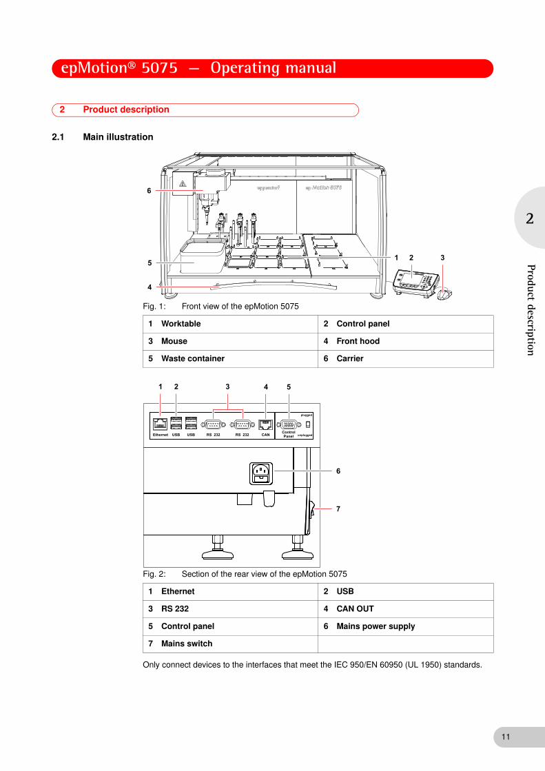
2.1 Main illustrationAbb. 1: Front view of the epMotion 5075
Fig. 1: Front view of the epMotion 5075
Abb. 2: Section of the rear view of the epMotion 5075
Fig. 2: Section of the rear view of the epMotion 5075
Only connect devices to the interfaces that meet the IEC 950/EN 60950 (UL 1950) standards.
1 Worktable 2 Control panel
3 Mouse 4 Front hood
5 Waste container 6 Carrier
1 Ethernet 2 USB
3 RS 232 4 CAN OUT
5 Control panel 6 Mains power supply
7 Mains switch
11

epMotion® 5075 — Operating manual
12
2
Prod
uct
desc
ript
ion
2.2 Delivery package
The following accessories for the epMotion are included in the standard scope of delivery:
The accessories for the epMotion 5075 LH are expanded by the following:
The accessories for epMotion 5075 VAC are expanded by the following:
The accessories for epMotion 5075 TMX are expanded by the following:
Quantity Order No. (International)
Order No. (North America)
Description
1 5346 000.017 - Control panel for epMotion
1 5075 782.006 - Cable mouse
1 5075 780.003 960002008 MultiMediaCard
1 5075 753.006 960002016 Waste container
1 – – Optical sensor
1 – –Power cableCompatible to the country where the order was placed or determined
1 5075 900.157 - Operating Manual epMotion 5075 with Control Panel, english
5075 900.165 - Operating Manual epMotion 5075 with Control Panel, german
1 – – Tool for transport safety device
Quantity Order No. (International)
Order No. (North America)
Description
1 5075 000.008 960020006
Automated pipetting system epMotion 5075 LHBasic device for Liquid Handling, includes Control Panel, software, Optical Sensor, waste container, MMC and reader, operating manual200 - 240 V, 50 / 60 Hz
Quantity Order No. (International)
Order No. (North America)
Description
1 5075 000.016 960020014
Automated pipetting system epMotion 5075 VACBasic device with vacuum station, includes control panel, software, optical sensor, waste container, MMC and reader, operating manual200 - 240 V, 50 / 60 Hz
1 – – Reservoir 400 mL
1 5075 784.009 960002253 VAC frame 1
1 5075 778.009 960002237 Vac frame holder
1 5282 000.018 960002270 Gripper
Quantity Order No. (International)
Order No. (North America)
Description
1 5075 000.733
Automated pipetting system epMotion 5075 TMXBasic device with Thermomixer, includes control panel, software, Optical Sensor, waste container, MMC and reader, operating manual200 - 240 V, 50/60 Hz, power plug Europe
Hint!
A detailed overview of the accessories and the article numbers can be found separately(see Accessories on p. 116).

epMotion® 5075 — Operating manual
2
Product description
2.3 Features
The epMotion 5075 can be supplied with a variety of dispensing tools which are inserted automatically. These dispensing tools and the appropriate pipette tips in each case (epT.I.P.S. Motion) can be used to dispense quantities of liquid in the volume range from 1 μL to 1000 μL.
The epMotion 5075 is available in the following versions:
• Liquid Handling (LH)
• Vacuum Unit (VAC)
• Thermomixer (TMX)
2.3.1 Principle of operation
The liquid is samples from the source tube in pipette tips, transported and deposited in the destination tube.
On request, an optical sensor automatically checks the correct selection and positioning of tubes, available supplies and the position of pipette tips in the rack, as well as liquid level in some tubes.
With the aid of predefined commands, you can create and edit simple or complex dispensing operations yourself and combine these into methods. In the process, you specify in the software, among other things, the source location and destination location as well as the desired dispensing or transport pattern.
The epMotion 5075 VAC is additionally equipped with a complete vacuum unit. This system is designed for the processing of vacuum-based high-throughput systems for nucleic acid purification in 96-well format, for example.
For further information, go to www.epMotion.com
13

epMotion® 5075 — Operating manual
14
2
Prod
uct
desc
ript
ion
2.4 Overview of hardware and labware
Familiarize yourself with the epMotion 5075 and the labware prior to first use.
2.4.1 Hardware
2.4.1.1 Worktable
The locations on the worktable differ depending on the variant supplied.
The locations for dispensing tools, gripper and thermal modules are identical for all variants:
• Locations T1 to T4 are provided for dispensing tools which you can position in any sequence. The locations of the dispensing tools are determined automatically following the start of a method. Determination starts at T1.
• Position the gripper and the gripper holder at location T0.
• Up to three locations (C1, C2, C3) can also be equipped with a thermal module.
Location B0 can only be accessed by dispensing tools if it is occupied by a 300 mL or 400 mL reservoir or similar labware.
1 Locations
A and B locations for labware, C locations optional for thermal modules, T locations for dispensing tools and gripper (optional). Depending on the variant, locations for vacuum unit and Vac Frame or the Mastercycler ep (see p. 14).
2 Control panel
3 Mouse 4 Front hood
Can be pushed up to open the inner space.
5 Mains switch
For switching on and off.
6 Waste container (standard)
The waste container can be autoclaved; can be washed in a dishwasher.
7 Directions of movement of the carrier 8 Dispensing tool
9 Carrier 10 Optical sensor

epMotion® 5075 — Operating manual
2
Product description
epMotion 5075 LH
The epMotion 5075 LH has 12 locations for labware (racks, plates, thermoracks and thermoblocks or tips). Up to three thermal modules can be located on the locations C1, C2 and C3.
epMotion 5075 VAC
The epMotion 5075 VAC has 11 locations for labware. There is also the vacuum unit at location B4. A Vac Frame can be temporarily stored on a Vac Holder in location C4. If you are using a Vac Lid, this is positioned in location T0. Up to three thermal modules can be located on the locations C1, C2 and C3. With the version with thermomixer and vacuum unit you cannot locate any thermal modules.
epMotion 5075 TMX
The epMotion 5075 VAC has 11 locations for labware. In addition a thermomixer is located on location A4. A thermal module can be optionally placed either onto location C1 or onto location C2. With the version with thermomixer and vacuum unit you cannot locate any thermal modules.
epMotion 5075 LH
Gripper Dispensing tools
T0 T1 T2 T3 T4 A 2 A 3 A 4
B 0 B 1 B 2 B 3 B 4
Waste
C 1 C 2 C 3 C 4 Option: Thermal module Option: Thermal module Option: Thermal module
epMotion 5075 VAC
Gripper Dispensing tools
T0 T1 T2 T3 T4 A 2 A 3 A 4
B 0 B 1 B 2 B 3
Waste
C 1 C 2 C 3 C 4 Option:Thermal module
Option:Thermal module
Option:Thermal module
Vacuumunit
Vac Holder
15

epMotion® 5075 — Operating manual
16
2
Prod
uct
desc
ript
ion
2.4.1.2 Worktable base adapter for the epMotion worktable
2.4.1.3 Dispensing tools (tools)
A total of six different dispensing tools is available for selection. For the three volume ranges 1 to 50 μL, 20 to 300 μL and 40 to 1000 μL a single-channel dispensing tool (TS xx) and an eight-channel dispensing tool (TM xx-8) are available in each case.
The dispensing tool required for a method is automatically picked up in the tool holder of the carrier and set down again once the dispensing task is complete.
The worktable base adapter for the epMotion worktable consists of a set of 4 screw-on feet for adjusting the height of the epMotion. The screw-on feet may only be installed by service personnel authorized by Eppendorf.
Abb. 4: Single-channel dispensing tool
Fig. 4: Single-channel dispensing tool
Abb. 5: Eight-channel dispensing tool
Fig. 5: Eight-channel dispensing tool
Dispensing tool Volume range
TS 501 μL – 50 μL
TM 50-8
TS 30020 μL – 300 μL
TM 300-8
TS 100040 μL – 1000 μL
TM 1000-8
5050

epMotion® 5075 — Operating manual
2
Product description
2.4.1.6 Gripper
The gripper is for transporting labware. The transport of labware is controlled in the software by means of the appropriate commands.
The 2 retaining pins on each of the gripper jaws hold the labware to be transported. Heavier labware is held by the pegs behind them.
The gripper is automatically picked up and set down by the carrier.
The gripper can transport the following labware.
• Thermoblock: joint transport of block with a plate on it as a fixed combination.
• Thermorack: joint transport of thermorack and tubes.
• Plates: all plates like MTP, DWP, skirted PCR plates and filter plates; also pick up or set down plates on height adapter and thermoadapter.
• Reservoir 300 mL and 400 mL: watch filling levels when transporting.
• Vac Frame: transport to the vacuum unit or holder for Vac Frame.
• Vac Lid: transport to the filter plate before the vacuum is switched.
The following labware cannot be transported.
• Tip racks
• Height Adapter
• Thermoadapter
• Tubes + Racks
• Tubs + Holders
2.4.1.7 Thermal module
Temperature control is effected with the aid of Peltier elements which cool or heat labware. A temperature of 0°C to 110°C can be selected for the thermal modules.
NOTICE!
Damage to the gold contacts from handling.
The function of the gold contacts of the gripper can be impaired through handling or contamination.
Do not touch the gold contacts.
WARNING!
Hazard when using flammable or explosive liquids.
Do not use explosive substances.
Heat slightly flammable substances only in small quantities below the boiling point.
Do not exceed the boiling point of solutions.
CAUTION!
Burns from hot surfaces.
Do not touch the metal surface of the thermal module if the method is interrupted or after it is complete.
Check the current temperature of the thermal modules. The temperature is displayed in the bottom part of the control panel display.
Wait until the thermal module has cooled down completely.
Hint!
If a PCR plate is placed directly on the surface of the thermal module, the wells are not temperature controlled as well and the secure location of the PCR plate on the thermal module may be impaired by relatively large tolerances in well dimensions.
Hint!
When heating tubes containing organic solvents or even water/solvent mixtures, observe the safety measures and safety data sheets applicable to the solvent or the mixture.
17
epMotion® 5075 — Operating manual
18
2
Prod
uct
desc
ript
ion
2.4.1.8 Thermomixer
The thermomixer can temperature control labware and mix. Temperature control is effected with the aid of Peltier elements which cool or heat labware. A temperature between 4°C to 95°C can be selected.
WARNING!
Danger of injury from ejected labware when using the Thermomixer command
When employing too heavy labware and using too high speeds labware can come loose from the holder and be hurled around.
Ensure that the front cover is closed and undamaged.
Select low speeds with heavy labware.
Only use compatible labware.
WARNING!
Hazard when using flammable or explosive liquids.
Do not use explosive substances.
Do not heat highly flammable substances on the thermomixer.
Heat slightly flammable substances only in small quantities below the boiling point.
Do not exceed the boiling point of solutions.
CAUTION!
Burns through hot thermomixer!
Do not touch the metal surface of the thermomixer if the method is interrupted or after it is complete.
Check the current temperature of the thermomixer. The temperature is displayed in the bottom part of the control panel display.
Wait until the thermomixer has cooled down completely.
CAUTION!
Contusion through moving thermomixer
The thermomixer can cause light contusion during operation if touched.
Ensure that the front cover is undamaged and is closed during operation.
Do not reach into the epMotion during operation.
NOTICE!
Physical damage due to cross contamination and splashing liquid when using the Thermomixer command
With too high liquid level in the tubes and too high speeds liquids can splash out from the tubes which damage the device and can lead to cross contamination.
Do not mix at high rotational speed with high liquid levels.
Hint!
The lowest temperature reached by the thermomixer depends on the ambient temperature and can be a maximum of 15°C below room temperature. With a room temperature of e.g. 20°C, the lowest temperature reached by the thermomixer is 5°C
Hint!
If a PCR plate is placed directly on the surface of the thermomixer, the wells are not temperature controlled as well and the secure location of the PCR plate on the thermomixer may be impaired by relatively large tolerances in well dimensions.
Hint!
When heating tubes containing organic solvents or even water/solvent mixtures, observe the safety measures and safety data sheets applicable to the solvent or the mixture.

epMotion® 5075 — Operating manual
2
Product description
2.4.1.9 Vacuum unit (epMotion 5075 VAC only)
In the vacuum unit, a vacuum pump generates a vacuum which enables the contents of filter plates to be extracted into a collecting vessel. For example, a nucleic acid purification or PCR cleanup process can run fully automatically. Filter plates can be positioned on the vacuum unit with the aid of the gripper.
Example of load
A collection vessel is first placed on the vacuum unit. A metal Vac Frame is used to lower the collection vessel into the vacuum manifold. A filter plate is placed on the Vac Frame. To improve the vacuum, a Vac Lid can be placed on the filter plate.
1 Vac Lid 2 Filter plate
3 Vac Frame 4 Collection vessel
5 Vacuum unit
1
2
3
4
5
19
epMotion® 5075 — Operating manual
20
2
Prod
uct
desc
ript
ion
2.4.1.10 Optical sensor
The optical sensor is located in a tube to the right of the carrier.
With the aid of an optical procedure the optical sensor measures the light reflection of surfaces, e.g., of labware on the worktable or of liquids placed in the tubes.
The optical sensor performs the following checking tasks on the epMotion 5075:
• detecting codes on tip racks and tube racks
• determining existing stocks of tips in positioned tip racks so that tip racks which have been started can also continue to be used
• checking whether the correct rack has been inserted (height detection)
• detecting height of plates
• detecting whether a location programmed as occupied on the worktable really is occupied
• detecting 30 mL or 100 mL reservoirs (tubs) and Module Racks in the Reservoir Rack
• automatically checking the adjustment of the entire device by means of exact measuring points on the surface of the worktable
• detecting the filling level of the liquids (liquid detection) in reservoirs, tubes and plates
To save time and depending on the requirements of the current method, you can use the software to activate or deactivate the individual functions of the optical sensor.
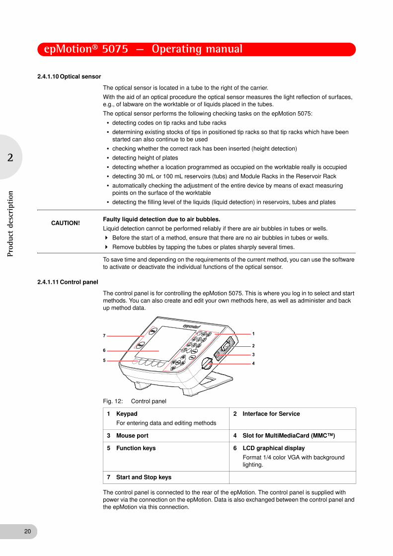
2.4.1.11 Control panel
The control panel is for controlling the epMotion 5075. This is where you log in to select and start methods. You can also create and edit your own methods here, as well as administer and back up method data.Abb. 12: Control panel
Fig. 12: Control panel
The control panel is connected to the rear of the epMotion. The control panel is supplied with power via the connection on the epMotion. Data is also exchanged between the control panel and the epMotion via this connection.
CAUTION!Faulty liquid detection due to air bubbles.
Liquid detection cannot be performed reliably if there are air bubbles in tubes or wells.
Before the start of a method, ensure that there are no air bubbles in tubes or wells.
Remove bubbles by tapping the tubes or plates sharply several times.
1 Keypad
For entering data and editing methods
2 Interface for Service
3 Mouse port 4 Slot for MultiMediaCard (MMC™)
5 Function keys 6 LCD graphical display
Format 1/4 color VGA with background lighting.
7 Start and Stop keys

epMotion® 5075 — Operating manual
2
Product description
2.4.1.13 MultiMediaCard (MMC™)
The MultiMediaCard (MMC™) is for backups. When you perform a backup of the data on the control panel, the program version and all labware specifications, including liquid types and applications in the epMotion 5075 memory, are copied to the MMC™.
Other functions of the MMC™ are Update and Transfer logfiles, together with Restore data. Abb. 14: Front of the MultiMediaCard (MMC™)
Fig. 14: Front of the MultiMediaCard (MMC™)Abb. 15: Gold contacts on the rear of the MultiMediaCard (MMC™)
Fig. 15: Gold contacts on the rear of the MultiMediaCard (MMC™)
If you create and edit methods on the PC, the MMC™ also serves for exchanging data between the control panel of the epMotion 5075 and the PC. The PC then has to be equipped with a USB card reader or a drive for MMC™ and the epMotion Editor software must be installed.
2.4.1.16 Waste system
The standard waste container can hold approx. 400 individually-ejected 1000 μL tips or correspondingly more of smaller tip sizes.
2.4.2 Labware
The following list gives you an overview of the labware of the epMotion 5075. More information on available labware components can be found in the appendix (see Labware on p. 123) as well as in the Internet at www.epMotion.com.
Labware Description Labware folder/
more information
Tubes You can use different tubes on the epMotion 5075 by loading module racks, racks and thermoracks:
• Safe-Lock tubes
• Standard tubes 3810X
• PCR tubes
• Falcon tubes and other tubes from various manufacturers
Equip Racks + Modules with Tubes
Racks Racks are tube holders for up to 24 tubes with various diameters.
You can position tubes higher with the aid of a spacer.
Equip Racks + Modules with Tubes
(see Racks for reagent tubes on p. 125)
Height adapter To keep carrier travel times and distances as short as possible, there are various height adapters (with a height of 40, 55 and 85 mm) which you can use to compensate for different heights of plates.
Adapters
(see Height Adapter on p. 135)
21

epMotion® 5075 — Operating manual
22
2
Prod
uct
desc
ript
ion
Plates You can use different plates on the epMotion 5075:
• Microplates (MTP) with 6, 24, 48, 96 or 384 wells
• Deepwell plates (DWP) with 24, 96 or 384 wells
• PCR plates with frame (skirted) with 96 or 384 wells
• Filter plates
• Tube plates with 96 individual tubes
• Rack for microtubes in a 96-well grid
Plates
(see Plates on p. 136)
Thermoadapter The PCR thermoadapter is used for temperature controlling 96-well and 384-well PCR plates. However, it does not form a fixed combination with a plate.
The thermoadapter DWP/96 is used for temperature controlling 96-well DWP plates. However, it does not form a fixed combination with a plate.
Adapters
(see Thermoadapter on p. 129)
Thermoblock The thermoblock is used for temperature controlling 96-well PCR plates (e.g., Eppendorf twin.tec semi-skirted or skirted). It forms a fixed combination with the plate which can only be moved together.
Thermoblocks with plates
(see Thermoblock (384 wells) on p. 128)
Thermoracks The thermorack with lid holder and 24 positions which can be temperature controlled is for the temperature control of smaller tubes (e.g., Eppendorf Safe-Lock tubes for 0.5 mL, 1.5 mL or 2 mL). The thermorack has a high heat capacity and a slower heat transfer i.e. it retains the temperature away from the temperature control over a longer time period. But it also takes longer to reach the desired temperature.
Equip Racks + Modules with Tubes
(see Thermoracks and thermoracks TMX on p. 127)
Thermoracks TMX The thermorack TMX with lid holder and 24 positions which can be temperature controlled is for the temperature-control of smaller tubes (e.g., Eppendorf Safe-Lock tubes for 0.5 mL, 1.5 mL or 2 mL). It is optimized for the application in the thermomixer as it is easier than the normal thermoracks and therefore permits higher rotational speed during mixing. It has a lower heat capacity but a faster heat transfer, i.e. it quickly reaches the desired temperature but does not retain it for long away from the temperature control.
Equip Racks + Modules with Tubes
(see Thermoracks and thermoracks TMX on p. 127)
Labware Description Labware folder/
more information

epMotion® 5075 — Operating manual
2
Product description
Reservoir rack The reservoir rack is for taking up to seven reservoirs or module racks.
Equip Holder with Tubs + Modules
(see Reservoirs and reservoir rack on p. 130)
Reservoirs (tubs) To supply liquids, reservoirs in sizes 30 mL and 100 mL are available. The reservoir rack carries up to seven reservoirs.
Equip Holder with Tubs + Modules
(see Reservoirs and reservoir rack on p. 130)
For larger volumes, an autoclavable reservoir with a capacity of 400 mL is available.
Tubs
Module racks TC reservoir rack modules (temperature controlled) are loaded with tubes and placed in the reservoir rack in the form of module racks.
Equip Holder with Tubs + Modules
(see Reservoir rack with module racks on p. 131)
Tips epT.I.P.S. Motion are pipette tips for single use with the epMotion. They are available in three volume sizes to suit the dispensing tools (50 μL, 300 μL and 1000 μL), in each case with or without filter. epT.I.P.S. Motion are available as racks or reloads.
Tips
(see epT.I.P.S. Motion on p. 124)
Tip Holder The Tip Holder is an adapter for holding the epT.I.P.S. Motion Reloads.
Labware Description Labware folder/
more information
23

epMotion® 5075 — Operating manual
24
2
Prod
uct
desc
ript
ion
2.4.3 Important volume terms for tubes and wells
The following remarks about volume terms are significant for selecting suitable tubes and plates and for some of the sequences when editing a method.
2.4.3.1 Filling volume
Maximum filling volume for a tube or well. A much larger volume is rejected by the software with an error message.
2.4.3.2 Working volume
The working volume for wells is primarily in the range of 50% of max. filling volume. In the case of larger tubes, the working volume is a correspondingly larger percentage. Statements about working volume should be understood as recommendations.
Low-contamination dispensing into the well or tube is possible up to the working volume with key classes of liquid.
MTP 96/384, PCR 96/384: fluid displacement in the working volume
When immersing tips in filled wells of 96-well and 384-well plates, volume displacement can cause the liquid to overflow if the optical sensor is switched off. You can avoid this by not exceeding the working volume in the wells.
To display the filling volume, mark the labware and press the Prop. function key.
Maximum immersion in wells is possible with all tips for 96-well plates and with 50 μL tips for 384-well plates (generally 1 mm from the bottom of the tube). To do so, select in a command (Sample Transfer, Reagent Transfer) the corresponding aspirate from bottom option (see Immersion depth and dispensing height (special) on p. 164).
1.5
1.0
0.5
0.1
Filling volumeWorking volume
Optical sensor detection limitRemaining volume removal
A Well filled up to working volume B Displacement if tip immersed to maximum depth before aspirating liquid
A B

epMotion® 5075 — Operating manual
2
Product description
2.4.3.3 Remaining volume
The term "remaining volume" refers to the volume which can no longer be aspirated from a tube, and which is dependent on tube geometry.
The pipette tip is generally immersed 3 mm in the liquid before liquid is aspirated. The pipette tip is moved downwards during aspiration of liquid. The immersion depth of 3 mm is maintained.
Under standard conditions, liquid can be aspirated up to the following limit data: 1.0 mm gap between the bottom of the tube and the pipette tip and simultaneously an immersion depth of the pipette tip into the liquid of 0.7 mm. The immersion depth of the pipette tip reduces at standard conditions at the tube bottom from 3 mm to 0.7 mm. The remaining volume is therefore calculated at standard conditions from a filling level of 1.7 mm.
Special cases for remaining volume
The initial immersion depth of 3 mm is included in the liquid type of the method. Higher immersion depths are only achieved if Aspirate from bottom is used. In the case of very tall tubes (e.g., primary tubes for blood), immersion to the bottom of the tube is not possible. In these cases, the remaining volume increases. There are consequently varying remaining volumes depending on tube type. Shorter 50 μL or 300 μL pipette tips and very tall tubes result in greater remaining volumes than the long 1000 μL pipette tip. Aspirations of liquid up to the remaining volume are liable to a greater risk of being incorrect. The curvature of the liquid surface could trigger falsified aspiration results.
Changing remaining volume
Under standard conditions the smallest distance between the pipette tip and the tube bottom is 1 mm. Exceptions are 30 mL and 100 mL reservoirs where it is 2.5 mm.
1.5
1.0
0.5
0.1
1.5
1.0
0.5
0.1
1.5
1.0
0.5
0.1
Hint!
Note the comments on adjusting bottom tolerance (see Set Bottom Tolerance on p. 183).
25

epMotion® 5075 — Operating manual
26
2
Prod
uct
desc
ript
ion
2.4.3.4 Multidispense
Reverse stroke in multi-dispensing Abb. 5: Multidispense before and after reverse stroke
Fig. 5: Multidispense before and after reverse stroke
In multidispense, a reverse stroke takes place after aspiration of the liquid. Here the sampled liquid is returned into the source tube. The volume of the reverse stroke is included in the aspiration volume and the required volume in the source tube. At the start of the method, these volumes are automatically included in the calculation of volume by the software.
The reverse stroke is of equal size in all liquids, but varies according to pipette tip.
Extra aspiration in multi-dispensing
Following the reverse stroke, there is more liquid in the pipette tip than is required for the dispensing steps. This extra aspiration is dispensed after dispensing is complete.
The dispensing of the extra aspiration depends on the tip change. The extra aspiration is returned to the source tube if no tip change has been defined before the liquid aspiration. The extra aspiration is dispensed into the waste container if the tips are changed before each aspiration of liquid.
When water is multidispensed, the following approximate extra aspirations result for each pipette tip:
• 50 μL tip: approx. 2.5 μL extra aspiration
• 300 μL tip: approx. 5.0 μL extra aspiration (only about 3.7 μL with single-channel dispensing tool)
• 1000 μL tip: approx. 35.2 μL extra aspiration
Aspiration volume
Aspiration volume is the volume which can be aspirated and which is required for the task in question. The volume is calculated at the start of the method from the sum of all aspirations.
The following volumes must be available in the source tube:
• 50 μL tip: approx. 5.8 μL reverse stroke
• 300 μL tip: approx. 45.2 μL reverse stroke (only approx. 16.7 μl with single-channel dispensing tool)
• 1000 μL tip: approx. 50.3 μL reverse stroke
The reverse stroke is of identical size with all liquids.
������
���
������
������
������
���
������
������
Hint!
When dispensing the defined errors for pipetting are exceeded(see Dispensing Tools on p. 113).
Hint!
In the case of multidispense, more liquid has to be aspirated for technical reasons than is calculated from the sum of all dispensing steps.

epMotion® 5075 — Operating manual
2
Product description
Example aspiration volumes with multidispense
A 96-well plate is to be filled with 10 μL water per well by the multidispense method. The eight-channel dispensing tool TM 50-8 is used. Aspiration is from one reservoir. Tips are not changed before the next aspiration of liquid.
Total aspiration volumes for multidispense:
• 10 μL for 96 wells: 960 μL
• 8 x 5.8 μL reverse stroke: 46.4 μL
• 8 x 2.5 μL extra aspiration: 20 μL
• Total: 1026.4 μL
The volume calculation of the software increases the sum total automatically be the remaining volume that cannot be aspirated from the source tube. We do not recommend using multidispense for water before a dispensing volume of 3 μL. With small volumes, pipetting always offers better free-jet capability as well as precision and correctness. With pipetting, only the required volume is aspirated and dispensed.
2.4.3.6 Required volume
Required volume is the total of "aspirated volume" and "remaining volume" in the tube. The minimum required volume is calculated at the start with the aid of the number of samples. For reasons of reliability (meniscus formation varies in the tubes), the "Required Volume" should always be exceeded.
2.4.3.7 Volume check
Knowledge of the software and how to use the control panel (see Overview of operation with the control panel on p. 36) is required to perform the volume check.
If it is known that the solution for dispensing has a density significantly different from that of water, check whether this needs to be compensated in the volume entry.
Perform the following check.
1. From the ep node and the Routine folder copy the Fill 96 method to your user directory.
2. Adapt the copied method to your own labware.
3. Weigh the corresponding plate empty.
4. Fill the plate in the epMotion with water with the aid of the modified method.
5. Weigh the plate again.
6. Repeat the process with the liquid to be tested and another plate.
7. Use the weighing results to perform a volume calculation (mass : density = volume). The density of water at 20°C is approx. 0.9982 mg/μL; take account of the density depending on the current temperature when converting (g/mL = mg/μL). In the case of the plate filled with water, you obtain a statement about the correctness of the dispensing tool for the selected volume. Assess the result with the test liquid accordingly, taking account of the density.
8. Depending on the result, adapt the volume in the commands. Rule of thumb: a change in density of 10% for identical dispensing conditions affects the dispensing result by between 0.2% and 1%.
9. Other physical variables (viscosity, vapor pressure, surface tension etc.) of the solution likewise affect the result.
27
epMotion® 5075 — Operating manual
28
2
Prod
uct
desc
ript
ion
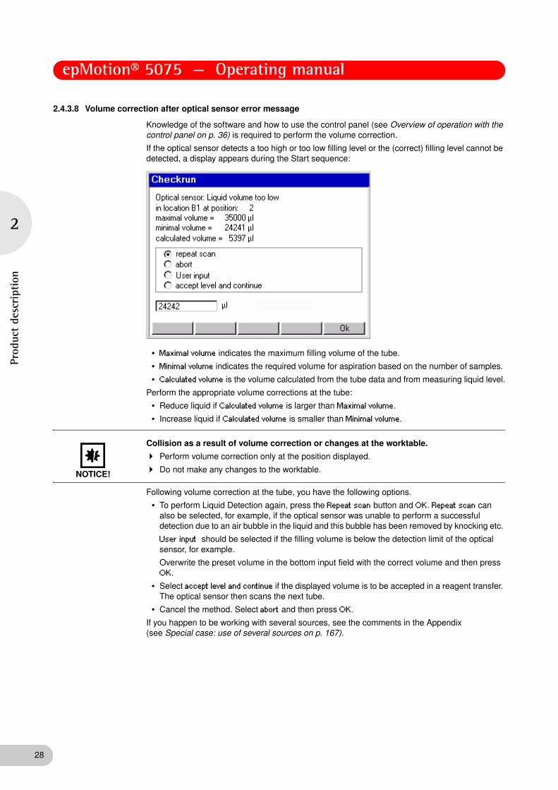
2.4.3.8 Volume correction after optical sensor error message
Knowledge of the software and how to use the control panel (see Overview of operation with the control panel on p. 36) is required to perform the volume correction.
If the optical sensor detects a too high or too low filling level or the (correct) filling level cannot be detected, a display appears during the Start sequence:
• Maximal volume indicates the maximum filling volume of the tube.
• Minimal volume indicates the required volume for aspiration based on the number of samples.
• Calculated volume is the volume calculated from the tube data and from measuring liquid level.
Perform the appropriate volume corrections at the tube:
• Reduce liquid if Calculated volume is larger than Maximal volume.
• Increase liquid if Calculated volume is smaller than Minimal volume.
Following volume correction at the tube, you have the following options.
• To perform Liquid Detection again, press the Repeat scan button and OK. Repeat scan can also be selected, for example, if the optical sensor was unable to perform a successful detection due to an air bubble in the liquid and this bubble has been removed by knocking etc.
User input should be selected if the filling volume is below the detection limit of the optical sensor, for example.
Overwrite the preset volume in the bottom input field with the correct volume and then press OK.
• Select accept level and continue if the displayed volume is to be accepted in a reagent transfer. The optical sensor then scans the next tube.
• Cancel the method. Select abort and then press OK.
If you happen to be working with several sources, see the comments in the Appendix (see Special case: use of several sources on p. 167).
NOTICE!
Collision as a result of volume correction or changes at the worktable.
Perform volume correction only at the position displayed.
Do not make any changes to the worktable.

epMotion® 5075 — Operating manual
3
Safety
3 Safety
3 Safety
3.1 Intended use
The device can be used in laboratories for research, development, industrial and routine work and training and education. Applications include but are not limited to the fields of life sciences, biotechnology, chemistry, clinical research, routine diagnostics. epMotion 5075 automated pipetting systems are designed for contamination-free, precise and correct measuring and transferring of liquids. The autoclavable dispensing tools work in a volume range from 1 μL to 1000 μL.
The epMotion 5075 VAC with integrated vacuum station, for example, carries out fully-automatic nucleic acid purification.
The epMotion 5075 TMX with an integrated thermomixer is used for applications which allow mixing and incubating with open tubes.
The epMotion 5075 meets the relevant fundamental requirements of the EC directives and standards listed in the declaration of conformity. epMotion 5075 automated pipetting systems are only to be used in rooms and must only be used by qualified staff with the appropriate training.
3.2 Information on product liability
In the following cases, the protection provided by the device may be impaired. The liability for the function of the device passes to the operator if:
• The device is not used in accordance with the operating manual.
• The device is used outside of the range of application described in the preceding chapters.
• The owner has made unauthorized modifications to the device.
3.3 Warnings for intended use
Read the operating manual first and observe the following general safety instructions before using the epMotion 5075.
WARNING!
Lethal voltages inside the device.
Ensure that the housing is always closed and undamaged so that no parts inside the device can be contacted by accident.
Do not remove the housing of the device.
Do not allow any liquids to penetrate the inside of the housing.
Do not allow the device to be opened by anyone except service personnel who have been specifically authorized by Eppendorf.
WARNING!
Electric shock due to damage to device or mains cable.
Only switch on the device if the device and mains cable are undamaged.
Only use devices that have been properly installed or repaired.
In case of danger, disconnect the device from the mains supply.
DANGER!
Danger of explosion!
Do not operate the device in areas where work is completed with explosive substances.
Do not use this device to process any explosive or highly reactive substances.
Do not use this device to process any substances which could create an explosive atmosphere.
29

epMotion® 5075 — Operating manual
30
3
Safe
ty
DANGER!
Damage to health from hazardous aerosols.
When working with substances that can be hazardous to health, harmful aerosols may form and escape from the vacuum pump in an uncontrolled manner.
Contact Eppendorf AG before starting to work with such substances.
WARNING!
Damage to health due to handling infectious liquids and pathogenic germs.
Observe the national regulations for handling these substances, the biological security level of your laboratory, the material safety data sheets and the manufacturer's application notes.
Wear personal protective equipment (PPE).
Follow the instructions regarding hygiene, cleaning and decontamination.
Comprehensive information on the regulations for handling germs and biological material in risk group II or higher can be found in the "Laboratory Biosafety Manual" (source: World Health Organization, Laboratory Biosafety Manual, in the valid version).
WARNING!
Hazard when using flammable or infectious liquids.
The waste container may contain residues of flammable or infectious liquids in ejected tips.
If you use flammable liquids (e.g., ethanol 98%), treat the waste before disposing of it in accordance with your laboratory guidelines.
Dispose of infectious material, waste or tips in accordance with national and local safety regulations.
WARNING!
Risk from incorrect supply voltage
Only connect the device to power supplies which correspond with the electrical requirements on the nameplate.
Only use sockets with a protective earth (PE) conductor and a suitable mains cable.
WARNING!
Risk to health due to contaminated device.
Perform decontamination before storing or dispatching the device and/or its accessories.
CAUTION!
Poor safety due to incorrect accessories and spare parts.
The use of accessories and spare parts other than those recommended by Eppendorf may impair the safety, function and precision of the device. Eppendorf cannot be held liable or accept any liability for damage resulting from the use of incorrect or non-recommended accessories and spare parts or from the improper use of such equipment.
Only use accessories and original spare parts recommended by Eppendorf.
NOTICE!
Damage and corrosion from spilled liquids.
Disconnect the power plug if relatively large quantities of liquid are involved.
Mop up spilled liquids immediately. When mopping up, pay particular attention to specifications in the safety data sheet.
Do not make long-term use of chemicals which form aggressive vapors (e.g., 37% hydrochloric acid). Aggressive vapors and chemicals can cause color changes to the surface or, in the course of time, cause damage to the moving parts and electronics.
NOTICE!
Damage and corrosion from liquids spilled in the vacuum unit.
Disconnect the power plug if relatively large quantities of liquid are involved.
Mop up spilled liquids immediately. When mopping up, pay particular attention to specifications in the safety data sheet.

epMotion® 5075 — Operating manual
3
Safety
NOTICE!
Damage to the device from the device tilting.
Note that during transport epMotion 5075 the center of gravity is at the back.
Follow national safety regulations regarding the transport of heavy loads.
Carry the epMotion 5075 using at least two people and reach underneath the device at the sides.
Place it on an even and strong work surface epMotion 5075 of sufficient bearing capacity. The device must not be placed on a trolley or at an angle. Check that it is horizontal using a spirit level if necessary.
NOTICE!
Damage from overheating.
Do not place the device close to sources of heat (e.g., radiator, drying cabinet).
Do not expose the device to direct sunlight.
Ensure free circulation of air by maintaining a distance of at least 6 cm from adjacent devices and the wall, on all sides of the device, and keep the underside of the device clear.
NOTICE!
Impaired function due to vibration.
Do not place the epMotion 5075 on a surface with devices which generate vibration (e.g.,vortex mixer, thermomixer, centrifuges).
NOTICE!
Size of disposables can change through autoclaving.
Do not use autoclaved disposable products in automated applications.
31

epMotion® 5075 — Operating manual
32
3
Safe
ty
3.4 Safety devices
This section explains the warning symbols on the epMotion and the location of the safety devices.
The front hood protects the user during operation of the device. A method can only be started if the front hood is closed. If the hood is opened with a method running, an error message is issued and the method is stopped.
1 WARNING
General hazard point. Follow the operating manual and in particular the safety notes.
2 WARNING
Do not reach into the device when a method is running!
3 DANGER
Risk of burns from hot surfaces.
4 The front hood serves as a safety device.
WARNING!
Risk as a result of defective screens or failure of the protective function.
Only operate the epMotion if screens are in perfect condition.
Ensure that the front hood is closed during operation (e.g., for methods or test runs).
Have defective screens replaced without delay.
CAUTION!
Risk of injury from movements by the carrier.
Press the Stop key on the control panel.
Wait until the carrier has completed its movements.
Only open the front hood when all the movements are complete.

epMotion® 5075 — Operating manual
4
Installation
4 Installation
4 Installation
Hint!
Installation of epMotion 5075 must always be carried out by Eppendorf AG or an Eppendorf AG service partner.
33

epMotion® 5075 — Operating manual
34
5
Ope
rati
on
5 Operation
5 Operation
5.1 First steps
5.1.1 Check correct installation
Before using the epMotion 5075 for the first time, please ensure
that the epMotion 5075 has been correctly connected and put into operation
that the device is not damaged in any way
5.1.2 Switch on the epMotion 5075 and log in as the user
Requirement
In order for you to be able to use your name to log in to the epMotion 5075, your administrator has to set up a user account for you. To do this, contact your in-house administrator. He will give you your user name and the associated PIN.
Detailed information on setting up user accounts is provided separately (see Create and edit a user account on p. 181).
Perform the following steps in the sequence described.
1. Switch on the epMotion 5075 at the mains switch.
The control panel switches on automatically and the software is loaded.
After loading, the User Login window appears in the control panel display .
Use the Contrast function key to reach contrast settings where you can change the brightness of the display.
NOTICE!
Damage from UV radiation.
UV radiation can cause color changes to the surface or, in the course of time, cause damage to the moving parts and electronics of the epMotion.
Avoid UV radiation.
Hint!
The epMotion 5075 may only be installed by personnel authorized by Eppendorf.
Hint!
epMotion can be operated with or without PIN protection.
If you are working with PIN, only the logged-in user can start or edit his methods. It is not possible to start methods belonging to other users. The logged-in user can view other people's methods and copy them to his directory. The administrator is automatically logged in with every user via his PIN.
If you are working without a PIN, all users have identical rights and can make administrator settings.

epMotion® 5075 — Operating manual
5
Operation
2. Select the user name from the list.
5. Press the OK function key to confirm the entry.
The navigation tree appears in the display of the control panel.
You are now logged in under your user name and can operate the epMotion 5075.
3. Click in the PIN field or press the Next key.
The cursor switches to the PIN field. 4. Enter your personal PIN using the numerical keys on the control panel.
Delete an incorrectly entered PIN using the Delete key and enter the PIN again. Delete deletes characters to the right of the cursor.
Next
DeleteDelete
2 3
5 6
0 .
8 9
abc
jkl mno
tuv wxyz
def1
7pqrs
4ghi
35

epMotion® 5075 — Operating manual
36
5
Ope
rati
on
5.2 Overview of operation with the control panel
This section gives you an overview of operating the epMotion 5075 with the aid of the control panel.
5.2.1 Menu structure Abb. 1: Control panel menu structure of the epMotion 5075
Fig. 1: Control panel menu structure of the epMotion 5075
Hint!
Sequences of actions in this manual are described for operation using the control panel. However, you can also operate the epMotion 5075 using the mouse.

epMotion® 5075 — Operating manual
5
Operation
5.2.2 Main navigation Abb. 1: Top level of the navigation tree
Fig. 1: Top level of the navigation tree
The navigation tree contains the following nodes (branches):
Eppendorf Eppendorf is the main node containing all the other nodes. If this node is marked, you can use the Prop. function key to display the software version of the control panel.
User directories For all users set up (in the example, Diego, Daniela). You can start the methods in your own user directory directly.
You can also edit these methods and save the changes or create completely new methods for your own applications or create folders.
EP Under this node you have available a number of predefined methods which you can copy into your own user directory in order to use them. You cannot start or edit the methods directly in the ep node. If this node is marked, you can use the Prop. function key to display the software version of the epMotion.
System This node contains the most important system settings. Some settings can only be edited by the administrator (see System settings on p. 182). In this node, each user can set contrast, export and delete a debug file and display and export the logfile.
Card This node is for transferring data between the internal memory and the MultiMediaCard (MMC™).
epMotion In this node, all the labware and the preset liquid types are administered. These settings can only be edited by the administrator.
5.2.3 Navigating in the navigation tree
To open a node in the navigation tree, you have three options:
Use the mouse to click on the minus symbol in front of the node.
Alternatively, double-click on the node with the mouse.
Use the mouse to click on the plus symbol in front of the node.
Alternatively, use the mouse to double-click on the desired node.
Alternatively, mark the node using the arrow keys and press Enter or the arrow key with the arrow facing right.
The node is opened and the plus symbol in front of the node changes into a minus symbol.
To close the node, follow the reverse sequence:
37

epMotion® 5075 — Operating manual
38
5
Ope
rati
on
5.2.4 Keys on the control panel Abb. 1: Keys on the control panel
Fig. 1: Keys on the control panel
The following keys are available on the control panel:
5.2.4.2 Enter key
Using the Enter key, you can:
• Confirm entries, e.g., your PIN when logging in.
• Execute the function of a selected, marked button, e.g., open the worktable if the Worktable button is marked.
• Open or close a marked selection list, e.g., to select the user name when logging in.
• Open or close a marked node in the navigation tree.
• Open a marked method in the navigation tree in order to edit it.
5.2.4.3 Next key
Use the Next key to move the cursor to the next input field or to the next button. The key is comparable to the Tab key on the PC which you can likewise use to switch between the fields of a form, for example.
Alternatively, mark the node using the arrow keys and press Enter or the arrow key with the arrow facing left.
The node is closed and the minus symbol in front of the node changes into a plus symbol.
Delete
Enter
Next
Stop
Start
2 3
5 6
0 .
8 9
abc
jkl mno
tuv wxyz
def1
7pqrs
4ghi
Enter
NextNext
Hint!
If you use the mouse, you can also click on any input field and any button directly with the mouse, rather than pressing the Next button.

epMotion® 5075 — Operating manual
5
Operation
5.2.4.4 Arrow keys
You can use the arrow keys to navigate step by step in the display, e.g., in lists and input fields and in the navigation tree.
• Within a List you have opened using the Enter key, you move up and down through the entries step by step using the arrow keys.
To select the marked option, press the Enter key again.
• Use the down arrow key to navigate from one field to the next.
• In input fields, in which you can enter text or numbers, you move from one character to the next using the right and left arrow keys.
• In the Navigation Tree you can reach all open nodes using the up and down arrow keys.
Using the right and left arrow keys you can open or close the currently marked node in the navigation tree.
5.2.4.5 Function keys with currently available functions in the display
The function keys have different functions depending on the software window in which you are currently located. The current function of every key is shown in the display directly above the key.
To execute a function, press the relevant function key.
5.2.4.6 Press the Start key
Use the Start key to start a marked method immediately.
5.2.4.7 Stop key
Use the Stop key to stop a current method. The current movement is completed before the method is stopped.
�� &RS\ 3DVWH 6DYH (GLW
Hint!
If you use the mouse, you can also click on the function directly in the display using the mouse instead of pressing the function key.
Start
StopStop
39

epMotion® 5075 — Operating manual
40
5
Ope
rati
on
5.2.4.8 Numerical keys
Use the numerical keys to enter numbers and text in input fields:
• To enter numbers, press the relevant numerical keys. For decimal numbers with numbers after the decimal point, use the period as a decimal point.
• To enter text, use the numerical keys as when writing a text message or SMS (Short Message Service) on a cellular phone: press the key with the relevant letter on it until the letter you want is displayed.
Example: to enter "pcr 3" in a text field:
– To enter the letter p: press key 7 once
– To enter the letter c: press key 2 three times quickly in succession
– To enter the letter r: press key 7 three times quickly in succession
– To enter the space: press key 0 (zero) twice quickly in succession
– To enter the number 3: press key 3 four times
5.2.4.9 Delete key
Use the Delete key to perform various deleting operations, e.g.,:
• in input fields:
– when the entire text in the input field is marked: delete the entire entry.
– when the cursor is located within the entry: delete letters and numbers one by one to the right of the cursor (use the arrow keys to move the cursor to the desired point if necessary).
• in the navigation tree: delete marked folders or methods.
• on the worktable: delete marked labware from the worktable.
• in the procedure: delete marked commands from the procedure.
5.3 Overview of Operating Sequence
In normal mode of the epMotion 5075, you generally perform the following sequences.
1. Position labware on the worktable
2. Select method and start
3. End method
As User, you can also perform the following sequences.
• Create and edit your own methods (see p. 44)
• Administer and backup data (perform backup) (see p. 184)
As Administrator with your own administrator PIN, you can also perform the following sequences.
• Compile your own labware from existing components (see p. 123)
• Configure the system (see p. 182) and administer user accounts (see p. 181)
Delete
2 3
5 6
0 .
8 9
abc
jkl mno
tuv wxyz
def1
7pqrs
4ghi
Hint!
You cannot enter capital letters and "." using the numerical keys.
"." can only be entered in comments using the software keyboard
Delete

epMotion® 5075 — Operating manual
5
Operation
5.4 Placing labware on the worktable
This section provides you with an overview of the supply of labware on the worktable.
5.4.1 Placing the gripper and gripper holder
Abb. 1: Open (A) and close (B) gripper jaws
Fig. 1: Open (A) and close (B) gripper jaws
Hint!
Beyond the preconfigured standard labware available ex works, it is also possible to dimension individual or external labware for use with the epMotion 5075 and to incorporate it in the labware directories of the software. For more information on this, contact Eppendorf Service.
CAUTION!
Burns from hot surfaces.
Check the temperature of the thermal modules before supplying the worktable. The temperature must be below 30°C.
NOTICE!
Material damage as a result of incorrect labware on thermal modules.
At temperatures in excess of 60°C, only use labware made of metal, polypropylene (PP) or polycarbonate (PC) on the thermal module! An additional check of the temperature set and the labware used is effected in the method.
CAUTION!
Risk of injury from sharp pins.
Cuts or other injuries to the skin from sharp pins on the insides of the gripper jaws.
Always grasp the gripper at the top and not inside at the gripper jaws.
1 Gripper jaws 2 Pin to locate gripper jaws
3 Holder 4 Pins
41
23
41

epMotion® 5075 — Operating manual
42
5
Ope
rati
on
1. Place the holder on a level work surface. The lateral pin on the holder points towards the user.
2. Press together the levers of the gripper simultaneously.
The gripper jaws open. The gripper jaw with the warning label points towards the user.
3. Position the slightly-open gripper over the holder so that the hole on the gripper jaw could take the lateral pin of the holder.
4. Allow the retaining pins to engage in the corresponding bores of the holder.
5. Check whether the lateral pin of the holder is located in the hole of the gripper jaw.
6. Place the holder and gripper in location T0.
5.4.2 Manually filling the vacuum unit (epMotion 5075 VAC)Abb. 1: Vacuum unit with supply variant
Fig. 1: Vacuum unit with supply variant
To supply the vacuum unit manually, perform the following steps.
1. Place the collection vessel on the vacuum unit. You can use a microplate (MTP), deepwell plate (DWP), tube plate or a filter plate as the collection vessel. The 400 mL reservoir can be used for tasks like binding or cleaning steps, for example.
2. Then place the Vac Frame on the collection vessel. If the Vac Frame is positioned incorrectly, it is impossible for an adequate vacuum to build up.
3. The weight of the Vac Frame lowers the collection vessel into the vacuum unit.
4. Place the filter plate in the Vac Frame.
5. If appropriate, place a Vac Lid on the filter plate. The "Vac Lid" label points towards the user.
1 Vac Lid 2 Filter plate
3 Vac Frame 4 Collection vessel
5 Vacuum unit
1
2
3
4
5

epMotion® 5075 — Operating manual
5
Operation
5.4.3 Position labware
Avoid placing very short labware next to very tall labware. Use a Height Adapter to compensate for the difference in height.
1. Position the dispensing tools on holders in any sequence in locations T1 to T4. The dispensing tools are fitted to and removed from the holder on the carrier fully automatically on the epMotion. The dispensing tools required for the method are detected by their coding.
2. For methods with Transport commands correctly position the gripper and holder in location T0. The gripper is fitted to and removed from the holder on the carrier fully automatically during a method run. The gripper is detected by its coding.
3. When using the vacuum unit with Vac Lid: place the Vac Lid on the holder for the gripper in location T0.
4. Position the Tip Rack in the location on the worktable in accordance with the method. In the process, the Tip Rack is pressed against the stops on opposite sides by the spring plate at the location.
5. Remove the lid from the Tip Rack.
6. When using Module Racks: place the filled Reservoir Rack on a B or C location (excluding B0). "A" locations may not be used.
7. Position the other labware required for your method in any locations. In the process, ensure that the labware is not tilted.
8. If desired, place a waste bag in the waste container and fix in position using the clamping ring. Pull the edge of the bag tightly downwards so that the path of the dispensing tool and access to the racks is not obstructed.
9. After supplying the worktable, close the front hood.
5.5 Create and start methods
5.5.1 Create new folder in user directory
To create a folder for your methods in your user directory, proceed as follows.
1. Mark the user directory.
2. Press the New Folder function keyfunction key.
3. Use the numerical keys on the control panel to enter a name for the new folder. Instead of the numerical keys you can also use the software keyboard which you reach via the Keybd function key.
Hint!
Use location B0 only for supplying with a 300 mL or a 400 mL reservoir. The dispensing tools cannot reach other labware (e.g., plates) without restriction, so that aspiration or dispensing of liquid is possible only to a certain extent and errors occur.
NOTICE!
The lid lies loosely on the tip rack.
Never grip the tip rack by its lid to lift it up, always by the side. Otherwise it will fall.
Only take off the lid shortly before starting the method. The lid protects the tips from contamination.
43

epMotion® 5075 — Operating manual
44
5
Ope
rati
on
4. To enter an additional comment to the new folder, use the down arrow key to go to the Comment field.
5. Use the numerical keys to enter a comment text and confirm with Ok.
The folder is set up and appears in the navigation tree under the node for your user directory.
You can change the name of the folder at any time using the Prop. function key.
5.5.2 Create and save methods
A method consists of two parts.
• Worktable: this is where you specify at which locations tips, racks, plates etc.are located.
• Procedure: this is where you define the sequence of a method with the aid of commands.
5.5.2.1 Create new method or cycler program
To create a new method or create a cycler program (epMotion 5075 MC only), proceed as follows.
1. In the navigation tree, open your own user directory and, if appropriate, the subdirectory in which you want to create the method/cycler program.
2. Press the New function key.New.
The New Method window appears , in which you can enter a name and a comment for the new method using the numerical keys.
3. From the Type selection list, select epMotion 5075 for a new method, and Mastercycler ep534X for a new cycler program. For detailed descriptions of cycler programs, see the operating manual for the Mastercycler ep.
4. Press the Ok function key.
The method is created and appears in the navigation tree in your user directory. The cycler program is shown in the navigation tree by a "C".
You can change the name of the method or the comment at any time with the aid of the Prop. function key.
Hint!
To protect a method from changes, you can mark it "read only". The method can then be displayed in "Show Mode" but not edited. Write protection can only be activated using the read only function once you have finished editing the method. The function is recommended when you are working without a PIN.

epMotion® 5075 — Operating manual
5
Operation
5.5.3 Load worktable
When compiling a method, start in Worktable mode and first load the worktable with the required labware. Then switch to Procedure mode to define the sequence of commands.
5.5.3.1 Edit method in worktable mode
To open a method for editing, proceed as follows.
1. Mark the method in the user directory and press the Edit function key.
The method is opened.
2. Mark the Worktable button and press Enter.
The worktable is opened. The list of available labware is displayed in the foreground, sorted by labware type. The display of locations is in the background.
3. To switch to the Locations display: press the Location function keyfunction key. Correspondingly, you switch back to the labware list via Labware.
5.5.3.2 Placing labware on the worktable
To position labware on the worktable, proceed as follows.
1. Select a labware type from the labware list and open it.
2. Select the desired labware and adopt by pressing Enter.
The selected labware is copied into the buffer memory and the display switches to the Locations display.
3. Mark the location in which the labware is to be positioned and press Enter.
The labware is positioned in the location.
45

epMotion® 5075 — Operating manual
46
5
Ope
rati
on
The Location Information window is opened, displaying information about this location.
4. If you would like to edit the name of the labware at this location: enter the name using the numerical keys.
5. If the Optical Sensor is to perform liquid detection at this location during the method, then set the desired option.
The following options are available.
Off:
Liquid detection is switched off at this location.
Random Access:
The Optical Sensor performs liquid detection at a few randomly selected positions of this labware.
All positions :
The Optical Sensor performs liquid detection at a few randomly-selected positions of this labware. Liquid detection should not be activated with racks and plates with 96 positions, as this is time-consuming.
You can reach the volume input window via the Volume function key.
6. Confirm the settings with the Ok function key.
The labware is positioned at the location.
Use the Info function key to reach the Location Information window. There you can change the labware name for the display on the worktable and set liquid detection.
7. Proceed in the same way to load the other locations on the worktable.
5.5.3.3 Remove labware from the Worktable
1. Mark the location from which you would like to delete labware.
2. Press the Delete key on the control panel.
A question appears in the display, asking whether you are sure you wish to delete the labware. Exit the query by pressing Yes or No.
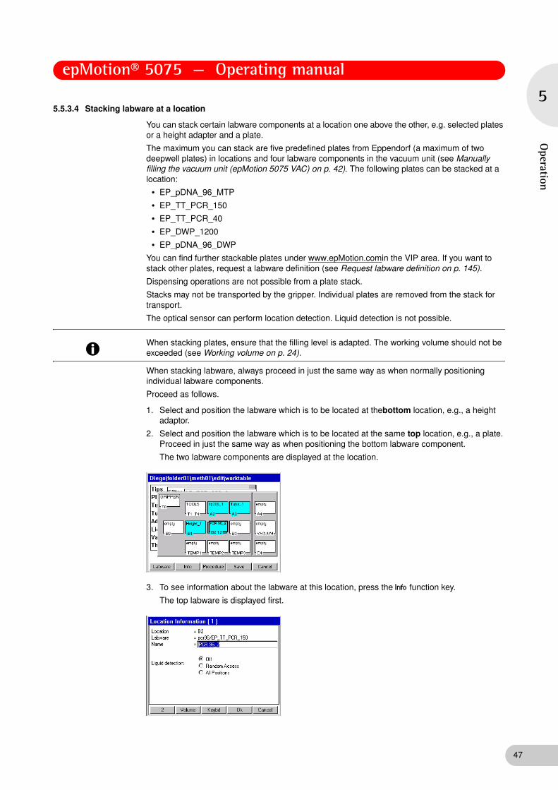
epMotion® 5075 — Operating manual
5
Operation
5.5.3.4 Stacking labware at a location
You can stack certain labware components at a location one above the other, e.g. selected plates or a height adapter and a plate.
The maximum you can stack are five predefined plates from Eppendorf (a maximum of two deepwell plates) in locations and four labware components in the vacuum unit (see Manually filling the vacuum unit (epMotion 5075 VAC) on p. 42). The following plates can be stacked at a location:
• EP_pDNA_96_MTP
• EP_TT_PCR_150
• EP_TT_PCR_40
• EP_DWP_1200
• EP_pDNA_96_DWP
You can find further stackable plates under www.epMotion.comin the VIP area. If you want to stack other plates, request a labware definition (see Request labware definition on p. 145).
Dispensing operations are not possible from a plate stack.
Stacks may not be transported by the gripper. Individual plates are removed from the stack for transport.
The optical sensor can perform location detection. Liquid detection is not possible.
When stacking labware, always proceed in just the same way as when normally positioning individual labware components.
Proceed as follows.
1. Select and position the labware which is to be located at thebottom location, e.g., a height adaptor.
2. Select and position the labware which is to be located at the same top location, e.g., a plate. Proceed in just the same way as when positioning the bottom labware component.
The two labware components are displayed at the location.
3. To see information about the labware at this location, press the Info function key.
The top labware is displayed first.
Hint!
When stacking plates, ensure that the filling level is adapted. The working volume should not be exceeded (see Working volume on p. 24).
47

epMotion® 5075 — Operating manual
48
5
Ope
rati
on
4. To switch between labware components in this location: press the number function key at the bottom left of the display.
5. Confirm the settings with the Ok function key.
The worktable is displayed.
6. To save the changes at the worktable press the function key Save Save.
5.5.4 Defining the procedure
When you have finished loading the worktable with the required labware, switch to Procedure mode and specify the sequence of commands the epMotion 5075 is to perform.
5.5.4.1 Open method for editing in procedure mode
You can reach Procedure mode directly from the worktable or when opening a method.
If the method is already open and you have previously edited the worktable, press the Procedure function key in the worktable display.function key .
If the method has not yet been opened, mark the method in the user directory and press the Edit function key. function key. Then mark the Procedure button and open by pressing Ok.
The procedure is opened. The list of available commands is displayed.
5.5.4.2 Brief overview of available commands
The following commands are available for defining the procedure.
Number of Samples
Use the Number of Samples command to specify how many samples are to be processed in the subsequent steps of the procedure. The command is used several times in a method if the number of samples changes during the sequence of the procedure.
Parameters/Options
• Fixed Number of Samples: activate this option if you would like to define a fixed number of samples.
• Maximum no. of Samples: with a fixed number of samples you enter the fixed number. In the case of a variable number of samples, enter the maximum number of samples.
• Comment: enter a comment, if required.
Sample Transfer
Using Sample Transfer you can transfer samples from several positions of a source labware to several positions of a destination labware.
Parameter
• Pipet. Tool/Filter Tips: select from the list the dispensing tool which is to be used for the transfer operation. If you are using filter tips, activate this function.
• Volume: enter the volume to be dispensed in each pipette or multidispense step.
Hint!
The user guide for editing a cycler program is described in the operating manual for the Mastercycler ep.
Hint!
The parameters and options for the commands are described using Sample Transfer. Parameters and options of individual commands which deviate from Sample Transfer are described separately.
Each command requires characteristic settings. For further detailed information about all commands and settings, see the Appendix.

epMotion® 5075 — Operating manual
5
Operation
• Pipette/Multidispense:
– Pipette: the volume set above is aspirated or dispensed in each step.
– Multidispense: the volume set above is dispensed in each multidispense step.
• Source/Destination: select source and destination labware from the worktable assignment.
• Pattern: the pattern is used to specify aspiration and dispensing positions within this command.
– Automatic pattern detection: mark the button next to Pattern and press Enter; a diagram of source/destination labware appears in the display. While you are defining a pattern, the software continuously determines the next possible position and indicates it in the form of a gray marking. Only regular patterns are permitted.
– Standard pattern: use standard to specify a simple standard pattern for sample transfer. For source and destination, the pattern is worked through in the x direction for row-wise (or in a plate, row-wise), and in the y direction for column-wise (or in a plate, column-wise).
– Free pattern (irregular): use "irregular" to select a pattern with any aspiration and/or dispensing position for the destination for a single-channel tool.
Options
• Special:
– Aspirate from bottom: select if the sample is to be aspirated from the bottom of the well.
– Dispense from top: select if the liquid is to be dispensed from the top edge of the well.
– Elution from filter: select if the liquid is to be aspirated from the PCR Cleanup filter plate.
• Change tips: select one of the available functions which specifies when the tips are to be changed.
• Mix before aspirating/Mix after dispensing: activate the relevant option if the liquid is to be mixed before aspiration/after dispensing. State the number of mixing cycles, speed and the volume to be mixed.
Fixed height: if you wish to give fixed height positions for mixing, then activate this option and enter the required values for aspiration and dispensing level.
Liquid types
If liquids whose physical properties of viscosity, vapor pressure and surface tension differ very significantly from those of water are to be dispensed, we recommend using a different liquid type.
• Standard liquid type: select the liquid type for the sample you wish to transfer.
• Change parameters: to change the settings for the selected liquid type for this command, activate the checkbox and set the values to suit your requirements.
• Set default: reset all values to default settings.
Reagent Transfer
A reagent is transferred from one position of the source labware to several positions of the destination labware.
Deviating parameters
• Pattern: no standard pattern available.
If you happen to be working with several sources, see the comments in the Appendix (see Special case: use of several sources on p. 167).
49

epMotion® 5075 — Operating manual
50
5
Ope
rati
on
Thermomixer
Use the Thermomixer command to specify the mixing parameters and the temperature of the thermomixer.
Deviating parameters
• Template: select as an option one of the pre-defined templates for different mixing tasks.
• Save: save your own templates.
• Speed on: activate this function if you want to mix.
– Speed: select a mixing speed between 300 - 2000 rpm.
– Time: select a time between 30 s and 120 min.
• Temperature on: activate this function if you want to temperature control.
– Keep temperature after method run: activate this option if the thermomixer is to retain the set temperature after the method has finished.
– Temperature: select a temperature between 4°C and 95°C.
Transport
The command uses the gripper to transport labware to a different destination location or to the Mastercycler (epMotion 5075 MC)/vacuum unit (epMotion 5075 VAC). Tips, racks, thermoadapters and height adapters cannot be transported. Semi-skirted and unskirted PCR plates can only be transported in combination with the thermoblock.
Deviating parameters
• Labware: select the labware to be transported.
• To location: select destination location for transport.
Dilute
The Dilute command is a modified Sample Transfer to make it easier for you to perform dilution series A defined volume is transported from one well to the next several times by means of pipetting.
Deviating parameters
• Transfer Type: here only Pipette is available.
• Special: Elution from filter not applicable.
• Pattern: no standard pattern available. Irregular pattern applicable only to source positions.
Pool
Use the Pool command to transfer liquids from several source positions to destination positions.
Deviating parameters
• Pattern: no standard pattern and no irregular pattern available.
• Special: Elution from filter not applicable.
Pool One destination
Use the PoolOneDest command to transfer liquids from several source positions to one destination position.
Deviating parameters
• Pattern: no standard pattern available. Irregular pattern applicable only to source positions.
• Special: Elution from filter not applicable.
Hint!
The lowest temperature reached by the thermomixer depends on the ambient temperature and can be a maximum of 15°C below room temperature. With a room temperature of e.g. 20°C, the lowest temperature reached by the thermomixer is 5°C

epMotion® 5075 — Operating manual
5
Operation
Mix
Use the Mix command to mix liquids within a position.
Deviating parameters
• Number of Cycles: enter the number of mixing cycles.
• Speed: specify mixing speed.
• Tool: select from the list the dispensing tool which is to be used for mixing.
• Filter tips: if you are using filter tips, activate this option.
• Mixing volume: enter the volume to be aspirated in each mixing cycle.
• Fixed height: if you wish to give fixed height positions for mixing, then activate this option and enter the required values for aspiration and dispensing level.
• Racks: select the racks, plates or tubes on the worktable on which the mixing command is to be executed.
• Pattern: no standard pattern available. No source and destination selection available.
Wait
The Wait command specifies a pause before the next step.
Comment
Use the Comment command to enter a comment line to be displayed at a particular point in the procedure.
User Intervention
The User Intervention command enables you to insert steps in your method which the user has to execute manually.
Vacuum
Only on epMotion 5075 VAC. Use the command to set the vacuum in the vacuum unit.
Deviating parameters
• Frame: select the Vac Frame.
• Vac. pressure: set the vacuum in kPa or mbar.
• Vacuum time: set the time for extraction.
• Use vacuum lid: activate this option if the gripper is to transport the Vac Lid from location T0 to the filter plate in the vacuum unit at the start of the command.
• Check levels: activate this option if all wells of the filter plate are to be scanned by the Optical Sensor following application of the vacuum. Check levels must not be preceded by a dispensing command.
Temperature
This command is used to specify the temperature of a thermal module.
Deviating parameters
• Location: select a thermal module.
• Temperature on: switch on temperature-control.
• Keep temperature after method run: activate this option if the selected thermal module is to retain the set temperature after the method has finished.
• Temperature: select a temperature between 0°C and 110°C for temperature control.
51

epMotion® 5075 — Operating manual
52
5
Ope
rati
on
StartCycler
Only on epMotion 5075 MC. Use this command to select a cycler program and specify the start. The StartCycler command must always be the last command of a method.
Deviating parameters
• Cycler Program: select the cycler program. Alternatively,
• Open user tree: alternatively, you can select the cycler program using this button in the navigation tree.
TempCycler
Only on epMotion 5075 MC with built-in Mastercycler ep. Use this command to select the temperature for the cycler lid and/or for the cycler block before the cycler starts.
Deviating parameters
• Lid temperature on: activate this option if the lid of the cycler is to be incubated.
• Lid Temperature: set the temperature of the lid.
• Block temperature on: activate this option if the block of the cycler is to be temperature-controlled.
• Block Temperature: set the temperature of the block.
5.5.4.3 Add command to procedure
Proceed as follows.
1. Open the method in Procedure mode(see Defining the procedure on p. 48).
The list of available commands is displayed.
2. Mark a command in the list and press the Add function key. .
The command is added to the procedure, e.g., in this case, the Number of Samples command.
3. To add another command, press the New Cmd function key .
The list of commands is displayed.

epMotion® 5075 — Operating manual
5
Operation
You now have the following options.
• To append the new command the end of the procedure: mark the command in the list and press the Add function key.
• To insert the new command above the currently marked line: mark the command and press the Insert function key. .
4. If necessary, edit the parameters of the inserted commands (see Remove command from procedure on p. 53).
5.5.4.4 Remove command from procedure
1. Mark the command which you want to delete from the procedure and press the Delete key.
A question appears in the display, asking whether you are sure you wish to delete the command.
2. To delete the command, press the Yes function key.
The command is deleted from the procedure.
5.5.4.5 Edit parameters of a command
This section describes how to proceed in general to edit the parameters of a command.
Each command has characteristic parameters.
Proceed as follows.
1. Mark the desired command in the procedure and press the Parameter function key function key.
The Parameters window for this command appears in the display, e.g. for a Sample transfer.
You can now edit the parameters.
2. Select a dispensing tool from the Pipet. Tool list. If you are using filter tips, activate the filter tips option.
3. Set the volume to be dispensed and select the transfer type (pipette or multidispense).
4. Select source and destination for the command: mark the button next to Source and Destination and press the Enter key. Then select the locations desired in each case.
5. Specify the pattern for the command: mark the button next to Pattern and press the Enter key. Then define the pattern.
53

epMotion® 5075 — Operating manual
54
5
Ope
rati
on
6. Specify further options for the command (e.g. liquid type, setting for mixing and changing tips): mark the button next to Options and press Enter. Then set the desired options. Detailed information about liquid types can be found in the Appendix (see Liquid options on p. 159).
5.5.4.6 Specify source and destination for command
This section describes how you proceed to specify the source and destination for a command.
Proceed as follows.
1. Open the Parameters window of the command.
2. Mark the button next to Source and press the Enter key.
A list of the labware you have previously defined for the worktable appears in the display.
3. Mark the desired source labware and adopt with Add.
The source location is defined and is shown in the display.
4. To add more source locations (a maximum of four locations is possible): press the New Rack function key.
The list of labware for the worktable appears in the display.
You have the following options.
• To append the new labware to the bottom of the list: mark the desired labware and press the Add function key.
• To insert the new labware above the currently marked line: mark the labware and press the Insert function key.
5. Specify further locations in the same way if required.

epMotion® 5075 — Operating manual
5
Operation
6. Confirm the selection using the Ok function key or Enter.
The source locations are displayed in the Parameters window of the command next to Source.
7. Mark the button next to Destination and press Enter.
8. Select one or more destinations for the command as described above for the source locations.
9. Confirm the selection with Ok.
The destination locations are displayed in the Parameters window of the command next to Destination.
5.5.4.7 Specify pattern for command
You can define Pattern using automatic pattern detection, simple standard pattern (Sample Transfer only) or free pattern (irregular). The patterns are independent of direction.
Example: define pattern for a Sample Transfer
The following section uses the example of the pattern for a Sample Transfer to describe how you specify a pattern for a command. The basic principle of compiling a pattern is identical for all commands.
1. Open the Parameters window of the command.
2. Define source and destination.
3. To define a simple standard pattern, next to Pattern activate the standard option and select the desired alignment.
Hint!
If you are using the reservoir rack with module racks and reservoirs in your method, you can only use irregular patterns.
Exception: the reservoir rack is occupied throughout with identically loaded module racks or reservoirs. In this case, the pattern with automatic pattern detection and the standard pattern (in the case of sample transfer) can also be used.
55

epMotion® 5075 — Operating manual
56
5
Ope
rati
on
This defines the simple pattern.
If you need a regular pattern with automatic pattern detection, a number of additional steps are required. The following example describes defining a pattern to pipette a sample from the first column of a source plate 1:1 into the second column of a destination plate. To do this, proceed as follows.
Regular pattern with automatic pattern detection
4. Mark the button next to Pattern and press Enter.
A diagram of the source plate appears in the display.
5. Using the arrow keys, mark the first position in the source plate from which liquid is to be aspirated (in the example, this is position A-1) and press Enter. If you want to adopt the proposed position, confirm this by pressing the Enter key.
The position is marked in color (blue in the example).
While you are defining a pattern, the software continuously determines the next possible position and indicates it in the form of a gray marking. If this proposal does not agree with your desired pattern, ignore the gray marking and continue defining your pattern.

epMotion® 5075 — Operating manual
5
Operation
6. Press the Destination function key.
A diagram of the destination plate appears in the display.
7. Mark the first position (or positions) in the destination plate to which the liquid is to be transferred (position A-2 in the example), and press Enter.
The position is likewise marked in color (blue in the example).
8. Press the Source function key.
The source plate appears in the display again.
9. In the source plate, select the second position from which you would like to aspirate liquid, e.g. position B-1.
The second position is marked in color (red in the example).
57

epMotion® 5075 — Operating manual
58
5
Ope
rati
on
10. Switch to the destination and select the position (or positions) to which the liquid is to be transferred from the second source position (in the example, position B-2).
The second position is likewise marked in color (red in the example).
In the example, the software detects the right pattern at this point: the next proposed step (the gray marking) matches the desired pattern in both the source plate and in the destination plate. You can thus confirm the pattern with Ok at this point.
In principle you have two options for assessing the pattern detected by the software.
• If you wish to discard the entire pattern, press the Cancel function key. Confirm the Save changed data? query with Yes.
You will then return to the Parameters window of the command. Start from the beginning with a new pattern.
• If the pattern proposed by the software is what you want, confirm with the Ok function key.
The software automatically completes the pattern up to the number of samples if this has been defined in a preceding Number of Samples command in the procedure. You will return to the Parameters window of the command.
The tick next to Pattern indicates that a pattern is defined for this command.
Standard pattern
Use standard to specify a simple standard pattern. The standard pattern can only be specified for the Sample transfer operation. For both the source and the destination, the pattern is worked through in the x direction in
– row-wise in the x direction or in a plate in rows (A1, A2, A3 etc.)
– column-wise in the y direction or in a plate in columns (A1, B1, C1 etc.)
Irregular pattern
Use irregular to specify a pattern with any aspiration positions for the source and/or any dispensing positions for the destination for single-channel dispensing tools. The irregular pattern can be defined as a function of the command for source, destination or both.
• Sample Transfer, Reagent Transfer: source and/or destination
• PoolOneDestination, Dilute: source (destination is not available)
• Mix, Pool: no irregular pattern possible

epMotion® 5075 — Operating manual
5
Operation
If you would like to reach a reservoir within a Module Rack, you must mark a position in row A and use the arrow keys to navigate to the reservoir. You do not reach the reservoir from positions in other rows (such as row B, row C etc.).
Replicates are not possible with this pattern.
5.5.4.8 Check an existing pattern
1. In the Parameters window of the command mark the button next to Pattern and press Enter. Then in the Pattern window, press the show pat. function key. .
The pattern is displayed as a sequence with color-coded positions.
You can stop the pattern being displayed if required by pressing the Stop button.
Use Source or Destination to switch between the source plate and the destination plate in the display.
2. To delete the existing pattern: press the function key new pat. in the pattern window.
You can now specify a new pattern.
5.5.5 Check method (parameter test)
Use the parameter test to check whether all the parameters required for the method have been set.
1. Open the method in Procedure mode (see Defining the procedure on p. 48).
The list of defined commands is displayed:
2. Press the TestPara function key..
The method is checked.
If parameters are missing, you will receive the appropriate messages.
3. Add the missing parameters and repeat the parameter test until you no longer receive any error messages.
Hint!
If you change the dispensing tool, the source or the destination, you will have to define a new pattern.
59

epMotion® 5075 — Operating manual
60
5
Ope
rati
on
5.5.6 Copy predefined methods into user directory
A number of predefined methods is available for you under the ep node in the navigation tree. To use them, copy these methods into your own user directory. Only then is it possible to start them.
To copy a method from the ep node into your user directory, proceed as follows.
1. In the navigation tree, open the ep node and within that, the directory containing the desired method.
2. Mark the method and press the Copy function key.
The method is copied into the buffer memory.
3. In the navigation tree, open your own user directory and within that, any subdirectory into which you would like to add the method.
4. Press the Paste function key.
The method is added to your user directory. You can now start or edit this method.
Instead of an individual method, you can also copy a whole method folder and all the methods it contains from the ep node into your user directory. To do so, proceed just as described above, but before copying, instead of marking an individual method, mark a method folder.
5.5.7 Activate and deactivate Optical Sensor
Perform the following steps to deactivate the Optical Sensor.
1. In the navigation tree, mark the epMotion node and press the Prop. function key.
The settings for the Optical Sensor are displayed. You can activate or deactivate the following settings individually:
Liquid Detection (level) :
If this option is active, the Optical Sensor checks the liquid level in the tubes if liquid detection has been specified for these tubes in the method.
Tips (type and quantity) :
If this option is active, the Optical Sensor checks the type and quantity of tips in the Tip Rack.
Locations (racks, tubs, height of plates, ...) :
If this option is active, the Optical Sensor detects the labware on the worktable and checks that it matches the method. In the process, the height of positioned labware components is also checked. In addition, coded racks are identified by their code being read.
2. Deactivate options and confirm the change with Ok.
The Optical Sensor is deactivated.
You can subsequently reactivate the settings in the same manner.
Hint!
The Optical Sensor can also be activated or deactivated for individual method sequences in Start mode using the Prop. function key.

epMotion® 5075 — Operating manual
5
Operation
5.5.8 Starting the method
1. In the navigation tree, open the user directory and, if appropriate, the subdirectory where the desired method is located and mark the method.
2. To view general information about this method and any comments: mark the method and press the Prop. function key.
An information window appears. You can check under Type, for example, whether the correct instrument is shown and check the comment in the Comment field. Close the information window by pressing Cancel.
3. To start the method: press the Start function key.Start.
Depending on the method, the Number of Samples window may appear.
4. Enter the number of samples for execution of the method and confirm with Ok.
Further Number of Samples windows for subsequent commands in the method may appear if these have been specified under Procedure.
5. Enter the number of samples for each command and in each case confirm with Ok.
A window appears with the labware load of the worktable which is stored in the method.
6. To obtain further information about a location in the method: mark the location in the display and press the Info function key. function key
7. Press the OK function key to close the information window.
8. When you have checked all the locations of the method with the worktable, press the Start key.
If the Optical Sensor is active, the set scans will be performed automatically. If you would like to change the settings of the Optical Sensor, press the Prop. function key in the worktable display.
The method will be executed. If intervention is required during the method, the relevant requests appear in the display.
If the Optical Sensor for liquid detection is switched off, the volume display appears.
NOTICE!
Damage as a result of incorrectly-positioned labware or dispensing tools.
Ensure before starting the method that the labware on the worktable is positioned exactly as defined in the method.
Ensure that the dispensing tool defined in the method is inserted. If the dispensing tool inserted does not correspond to the one defined in the method, an error message appears.
61

epMotion® 5075 — Operating manual
62
5
Ope
rati
on
9. Check the volume and correct it if it is below the min. volume required.
Start Cycler program
In general, a method with the required dispensing steps then the cycler program are performed. Selection and start of the cycler program are specified in the method.
To start a cycler program
• Have the PCR plate filled in an epMotion method, cover with the CycleLock and transport into the cycler. This completes the method. You can perform a pure epMotion method in parallel following the start or while the cycler program is running. The cycler program starts when the motorized lid is closed.
5.5.9 Observations, method run
After a method is started, the procedure and the commands are displayed. The command currently being executed is highlighted in color.
• All liquids are dispensed in free jet mode.
• Before each x and y movement of the carrier, the aspirated liquid in the tip is drawn up so that there should always be air in the bottom part of the tip during the x and y movements of the carrier. If there is no air bubble, faulty dispensing operations will result. Check the filling volume entry with the tubes (exception: using the Elution from filter option in the Sample Transfer command.) In this case the volume entry must be corrected and the method must be completely repeated.
• After Multidispense, then depending on the specification under Change tips, remaining liquid will be dispensed back into the source or into the waste container.
Abb. 1: Tip with and without air bubble
Fig. 1: Tip with and without air bubble
Hint!
We recommend performing the following test runs before starting a method:
• Test run without Tip Racks or labware and with the Optical Sensor deactivated.
Closely observe the travel of the carrier and check whether it agrees with the method.
• Test run with Tip Racks, the correct labware and the Optical Sensor switched on. Instead of the actual samples and reagents, use water with the correct filling volumes and dispensing quantities.
Check that dispensing is correct across the entire method.
Hint!
You can also start a cycler program independent of the epMotion method.
NOTICE!
Faulty dispensing as a result of exchanged labware or topping-up of liquids.
When a method is running, follow the requests in the display.
Do not remove or exchange labware.
Do not refill the source tube.

epMotion® 5075 — Operating manual
5
Operation
5.6 Stop or interrupt methods
5.6.1 Stop method prematurely
If you have to stop the method prematurely,
5.6.2 Service commands after a method is stopped
If you have stopped a method, you can use the service commands:
• To open the gripper and remove labware
• To remove the gripper from the holder of the carrier
• To remove the dispensing tool from the holder of the carrier
To call up the service commands
1. Open the epMotion node and the Service directory.
The list of service commands is displayed
The following commands are available.
• Carrier
– Home: moves the carrier over the waste container. This position is recommended for removing the gripper or a dispensing tool. Do not use Home if this could cause a crash situation with other labware on the worktable!
• Tool interlock:unlocks or locks a dispensing tool or the gripper without labware. Before unlocking, open the front hood and hold the dispensing tool or the gripper firmly.
• Gripper: if the gripper is marked, function keys are available for opening and closing the gripper jaws. Before unlocking the gripper, first remove the appropriate labware at this point: open the front hood, hold the labware in one hand (wearing safety gloves if necessary) and press the Open function key
• Vacuum chamber: displays the current vacuum in mbar.
CAUTION!
Burns from hot surfaces.
Do not touch the metal surface of the thermal module if the method is interrupted or after it is complete.
Check the current temperature of the thermal modules. The temperature is displayed in the bottom part of the control panel display.
Wait until the thermal module has cooled down completely.
CAUTION!
Burns through hot thermomixer!
Do not touch the metal surface of the thermomixer if the method is interrupted or after it is complete.
Check the current temperature of the thermomixer. The temperature is displayed in the bottom part of the control panel display.
Wait until the thermomixer has cooled down completely.
CAUTION!
Burns from hot surfaces.
Do not touch the CycleLock frame in the cycler if it is interrupted or once a method is complete (ep Motion 5075 MC only).
Wait some time for the frame to cool down before removing it.
Press the Stop key.
Use the Stop key to stop a current method. The current movement is completed before the method is stopped.
Stop
63
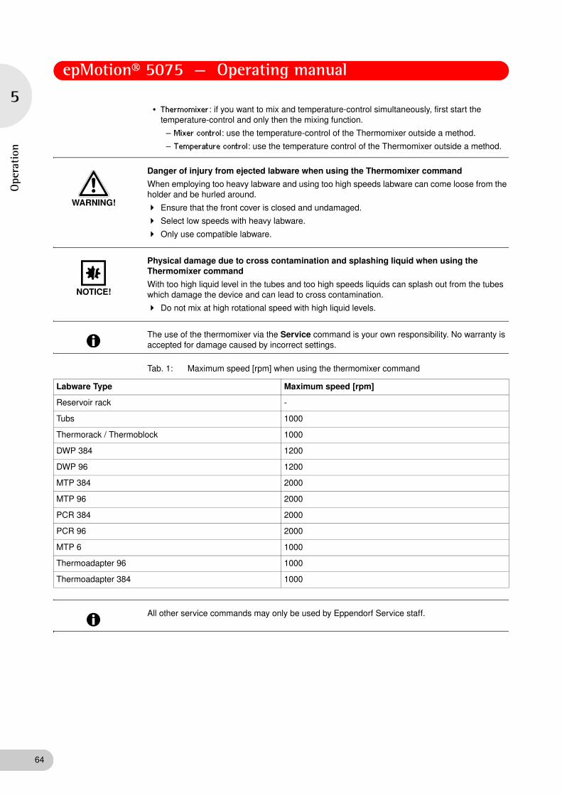
epMotion® 5075 — Operating manual
64
5
Ope
rati
on
• Thermomixer: if you want to mix and temperature-control simultaneously, first start the temperature-control and only then the mixing function.
– Mixer control: use the temperature-control of the Thermomixer outside a method.
– Temperature control: use the temperature control of the Thermomixer outside a method.
Tab. 1: Maximum speed [rpm] when using the thermomixer command
WARNING!
Danger of injury from ejected labware when using the Thermomixer command
When employing too heavy labware and using too high speeds labware can come loose from the holder and be hurled around.
Ensure that the front cover is closed and undamaged.
Select low speeds with heavy labware.
Only use compatible labware.
NOTICE!
Physical damage due to cross contamination and splashing liquid when using the Thermomixer command
With too high liquid level in the tubes and too high speeds liquids can splash out from the tubes which damage the device and can lead to cross contamination.
Do not mix at high rotational speed with high liquid levels.
Hint!
The use of the thermomixer via the Service command is your own responsibility. No warranty is accepted for damage caused by incorrect settings.
Labware Type Maximum speed [rpm]
Reservoir rack -
Tubs 1000
Thermorack / Thermoblock 1000
DWP 384 1200
DWP 96 1200
MTP 384 2000
MTP 96 2000
PCR 384 2000
PCR 96 2000
MTP 6 1000
Thermoadapter 96 1000
Thermoadapter 384 1000
Hint!
All other service commands may only be used by Eppendorf Service staff.

epMotion® 5075 — Operating manual
5
Operation
5.6.3 Continue method
Press the Continue function key.
The method is continued.
Alternatively:
Press the Step function key.
The next sub-step is executed.
5.6.4 Abort method
Press the Abort function key. Abort.
The display shows a query. The method is aborted and cannot be continued.
5.7 epMotion 5075 Shut Down and Switch Off
Perform the following steps in the sequence described.
1. Mark the top Eppendorf node.
2. Press the Shutdown function key.
A message appears in the display that the Shutdown command will end all processes currently running.
3. Press Shutdown again.
The epMotion 5075 shuts down and the appropriate message appears in the display.
4. Switch off the epMotion 5075 at the mains switch.
Hint!
To continue a method, the following points have to be guaranteed:
• The carrier has not been moved manually
• The tubes on the worktable have not been topped up
• Tips have not been removed
• Tip Racks and tubes have not been exchanged
WARNING!
Hazard when using flammable or infectious liquids.
The waste container may contain residues of flammable or infectious liquids in ejected tips.
If you use flammable liquids (e.g., ethanol 98%), treat the waste before disposing of it in accordance with your laboratory guidelines.
Dispose of infectious material, waste or tips in accordance with national and local safety regulations.
NOTICE!
Loss of data as a result of switching off the device.
Press the Shutdown function key before switching off the device.
65

epMotion® 5075 — Operating manual
66
6
Qui
ck S
tart
6 Quick Start
6 Quick Start
6.1 Short instructions
6.1.1 Select the method and start
1. Switch on the epMotion.
The software is loaded and then the UserLogin display appears. Log in as a user as follows.
2. Select the user with the arrow keys from the User list and use the Next key to navigate down to the PIN field.
3. Enter the PIN via the number keys and press the Ok function key.
The navigation tree is displayed, your user directory is marked.
4. Open the user directory using the Enter key and mark the desired method using the arrow keys.
5. Press Start.
Depending on the method, the Number of Samples window appears or in the case of methods with a fixed number of samples, the worktable. For Number of Samples: enter the number of samples in the display as requested and then press Ok.
6. In the Worktable display, check the loaded worktable and confirm with Ok.
If volume entries are necessary, the displays for volume input will appear automatically. Exception: labware with a volume of "0" (generally destination). If a volume change is required, mark the labware and use the Volume and Info function keys to navigate to the volume entry. Enter the volumes in μL and confirm with the Ok function key.
7. Check whether the labware shown in the display is located at the relevant locations of the worktable and that all locations shown in the display as "empty" are indeed empty.
8. Check whether the tip racks have enough tips in them and that all tubes are open and the waste container is empty.
9. Close the front hood and press Start.
10. The epMotion automatically checks whether dispensing tools and gripper are present.
Start the scanning procedures of the optical sensor, the method is executed. The dispensing and transport steps are carried out.
11. Follow the instructions of the display (e.g., to replace tubes etc.).
12. To switch off the epMotion, press Shutdown and follow the operator instructions.
Hint!
Only trained staff who are already familiar with the operating manual and the epMotion may work according to these short instructions. Observe the safety precautions.
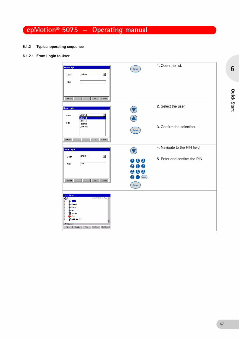
epMotion® 5075 — Operating manual
6
Quick Start
6.1.2 Typical operating sequence
6.1.2.1 From Login to User
1. Open the list.
2. Select the user.
3. Confirm the selection.
4. Navigate to the PIN field
5. Enter and confirm the PIN
Enter
Enter
Delete
2 3
5 6
0 .
8 9
abc
jkl mno
tuv wxyz
def1
7pqrs
4ghi
Enter
67

epMotion® 5075 — Operating manual
68
6
Qui
ck S
tart
6.1.2.2 Starting the method
1. Open the directory.
2. Open the folder, mark the method.
Number of samples does not appear in methods with a fixed number of samples.
3. Enter and confirm the number of samples
If you would like to check the settings of the Optical Sensor,
4. Press the Prop. function key.
5. Check the loaded worktable.
6. Press the Start function key.
The window for volume input appears. Check the volume and confirm with Ok.
7. If liquid detection is deactivated, enter the volume manually and confirm with the OK function key.
Enter
Enter
Start
Delete
2 3
5 6
0 .
8 9
abc
jkl mno
tuv wxyz
def1
7pqrs
4ghi
Enter
Delete
2 3
5 6
0 .
8 9
abc
jkl mno
tuv wxyz
def1
7pqrs
4ghi
Enter

epMotion® 5075 — Operating manual
6
Quick Start
6.1.2.3 Create a new method and edit the worktable
1. Open the directory.
2. Press the New function key.
3. Enter a new name for the method or adopt the old name.
4. Press the Edit function key.
5. Open the worktable.
6. Select the required labware, e.g., Plates.
7. Open the list of plate types
8. Select the plate type.
9. Open the list of plates
Enter
Enter
Enter
Enter
Enter
69

epMotion® 5075 — Operating manual
70
6
Qui
ck S
tart
10. Select the plate.
11. Adopt the selected plate.
12. Mark the location.
13. Position the labware.
14. Press the Labware function key.
15. Load the worktable as described above and press the Procedure function key.
Enter
Enter

epMotion® 5075 — Operating manual
6
Quick Start
6.1.2.4 Edit procedure (example: Sample Transfer)
6.2 Example method
6.2.1 Method objective
A suitable volume of a PCR Mastermix is to be dispensed into a PCR 96-well plate from a Thermorack supplied with 1.5 mL Eppendorf micro test tubes. The DNA samples from an MTP 96-well plate are then pipetted into the relevant wells of the PCR 96 plate and the PCR mixture carefully mixed. In this example, the volume of the mixture is 20 μL.
6.2.2 Sample preparation
1. Prepare the Mastermix in a 1.5 mL Eppendorf micro test tube and position in the Thermorack. In the process, take account of the calculations for aspiration volumes (see Aspiration volume on p. 26).
2. Transfer eight DNA samples with a volume of at least 50 μL to the MTP 96 plate in any sequence.
1. Open the list of commands.
2. Select Sample Transfer.
3. Adopt Sample Transfer.
Press the Parameter function key.
4. Navigate to the settings, make settings as appropriate.
• Pipet. Tool: set the dispensing tool, select filter tips if required
• Volume: enter volume
• transfer type: select pipette or multidispense
• Source/Destination: select source and destination
• Pattern: define pattern
You can set additional functions via Options.
Enter
Enter
Enter
Hint!
You can also perform a test run using distilled water.
71

epMotion® 5075 — Operating manual
72
6
Qui
ck S
tart
6.2.3 Method sequence
6.2.3.1 Log on and create a new method
1. Log on as the user and press New to define a new method.
The New Method / Cycler Program window is opened. In this window, you can assign a new method name or adopt the proposed name.
2. Exit the window by pressing OK to return to the navigation tree and the user directory.
6.2.3.2 Supply the worktable
1. With the method marked, press the Edit function key to obtain access to Worktable or Procedure.
2. Press Edit again to open the worktable.
A window appears with a list of predefined labware from which you have to select the tubes necessary for the method.
3. Select Tubes + Racks + (Thermo)racks + Modules and press Enter to select the Thermorack (Rack_1_5ml) labware.

epMotion® 5075 — Operating manual
6
Quick Start
4. Press Location to reach the worktable. Mark location C2 (TEMP2) with the cursor and press Enter.
The Location Information window appears, displaying information about the rack which has been positioned.
5. Check whether All positions is marked for liquid detection by the Optical Sensor. Then press OK. Supply the worktable with the appropriate remaining labware.
6. Under Tips in the labware list, select the 50 μL tips (tip50) and put these in location A2. To confirm and to open the Location information window, press Enter. Exit the window by pressing OK.
7. Under Plates and then under MTP 96, select the MTP 96 plate (EP_pDNA_MTP_96) and put it in location B3. Confirm again with Enter and check in the Location information window whether Off is selected. Liquid detection is very time-consuming for plates with 96 wells.
8. Under Plates and PCR 96, select PCR plate EP_TT_PCR_150 and position in location B2. Confirm with Enter and check under Location information whether Off is selected for liquid detection.
9. As you supply the worktable, also use the software to organize the actual positioning of vessels on the worksurface.
10. Save with Save.
6.2.3.3 Define procedure
1. Use Procedure to reach the programming of the individual commands.
The empty method sequence is displayed with the list of available commands.
73

epMotion® 5075 — Operating manual
74
6
Qui
ck S
tart
2. Select the Number of samples command using the cursor. To specify the command as the first method entry in the Procedure, press Enter.
3. Press Parameter to reach the parameter settings.
4. Select the Fixed parameter and enter 8 as the number of samples. Confirm with OK.
5. Use the cursor to access the second command line. Use the NewCmd key to enter the Reagent Transfer command. Proceed as described for the Number of samples entry. Use the Parameter key to make the following settings.
6. Pipet. Tool: select TS_50.
7. Volume: enter 15 μL.
8. Mark multidispense.
9. Mark the button next to Source and use Enter to open the selection of worktable labware previously specified. Select the Thermorack (Tube_1) as source vessel and confirm with OK.
10. Correspondingly use the button next to Destination to select the PCR plate (PCR96_1) from the worktable labware list as the destination.
11. Use the button next to Pattern to reach automatic pattern specification. Irregular may not be selected. The pattern display for the source is displayed.
12. Mark the position with the prepared Mastermix and select by pressing Enter (gray marking turns blue).
13. Press Destination and mark the wells of the first column (A1, A2 etc.) and confirm with Enter (gray marking turns blue). Exit the pattern by pressing OK. The tick next to the Pattern button shows that a pattern is defined.
14. Under Options you come to the Change Tips setting in which when command is finished must be marked. Press OK twice to confirm the selection and return to the method procedure.
15. Mark the third command line (under Reagent transfer) and press New Cmd. Use the arrow keys to select the Sample transfer command. Use Parameters to make the following settings.
16. Pipet. Tool: select TS_50.
17. Volume: enter 5 μL.
18. Mark pipette.
19. Mark the button next to Source and use Enter to open the selection of worktable labware previously specified. Select the MTP 96 plate (MTP96_1).
20. Correspondingly use the button next to Destination to select the PCR plate (PCR96_1) from the worktable labware list as the destination.

epMotion® 5075 — Operating manual
6
Quick Start
6.2.3.4 Define pattern and save settings.
1. Next to Pattern, select the irregular field. By selecting irregular, you can define an irregular pattern for the samples provided. The Source and Destination selection fields appear. Mark Source to specify the samples of the MTP plate as the source.
2. Use the button next to Pattern to reach pattern specification. The pattern display for the source is displayed.
3. Mark the first position where the first sample is located and press Destination.
4. Mark the first well A1 and confirm with Enter. After each individual entry, switch between source and destination (see Specify pattern for command on p. 55). As the irregular entry was specified only for the source, the individual wells of the destination can only be selected in the regular pattern and not at will.
5. Confirm the selection using Enter and exit the pattern with OK.
6. Under Options you reach the Change tips setting where before aspiration from next well, tube or position has to be marked. Press Liquid to return to the Options.
7. Select the function mix after dispensing. Use the button which appears to enter the mixing volume of 10 μL and increase the number of mixing cycles (No. of cycles) to 5. The remaining settings are retained. Confirm with OK.
8. Press OK twice to return to the method sequence.
6.2.3.5 Test and save settings
1. Check all parameter settings using TestPara. In the event of error messages, the incorrect settings need to be corrected.
2. Use Save to save the method and then exit editing mode by pressing Exit. The user directory is displayed.
6.2.4 Start method
1. Start the method.
The worktable is displayed.
2. Use the Prop. key to activate all detection functions of the Optical Sensor (if desired) and confirm with OK.
3. Press Start again to start the method running.
A volume query appears for the MTP 96 plate, as Off was previously set for liquid detection.
4. Enter 50 μL as the volume and confirm.
75

epMotion® 5075 — Operating manual
76
7
Trou
bles
hoot
ing
7 Troubleshooting
7 Troubleshooting
7.1 Error search
If a method does not start running after Start, check the following points. Note that the Labware on the worktable must match the method.
• Is plate or rack correctly inserted and not the wrong way round?
• Is a height adapter with the correct height being used?
• Are all the plates, racks, tips, tubs etc.shown in the display present on the worktable of the instrument?
• Are the necessary dispensing tools correctly suspended in the holders in locations T1 to T4?
• For methods with Transport commands: Has the gripper in location T0 been correctly positioned by hand?
• For epMotion VAC and methods using the vacuum unit: are all components of the vacuum unit correctly positioned?
• For epMotion MC: is the mat for the CycleLock level in the frame? Is the texturing of the mat facing upwards and is the mat not in contact with the base of the location?
• Are all tubes and tubs open?
• Are the tip racks filled with enough tips and have the lids been taken off the tip racks?
• Is the lid of Safe-Lock tubes correctly positioned?
• Are all the locations on the worktable of the instrument indicated as empty in the display really empty?
• Is the correct dispensing tool inserted and is it undamaged?
• Are the necessary filling quantities for the source present?
• Are racks or plates subsequently required for the parking positions ready and has their volume been entered?
7.2 General errors
7.2.1 Read error of the optical sensor
Symptom/message Cause Remedy
Read error of the optical sensor in detecting labware
Plates such as MTP, DWP, PCR etc. are not level on the worktable surface or have been inserted inverted.
Check that the labware has been correctly inserted into the location.
Read error of the optical sensor in detecting labware
The plastic plate is not detected.
The cause might be a minor unevenness in the the plastic surface. Such unevenness is usually not visible.
Wipe a moist cloth several times over the detection range of the optical sensor on the labware.
Repeat the Location detection with a still lightly moist surface.
Read error of the optical sensor in detecting the pipette tips
Problem when detecting pipette tips. Turn the tip rack by 180°.
Read error of the optical sensor in detecting the fluid level
Fluid surface not level (strong meniscus formation).
Carefully tap the rack or plate on the table until the surface is level.
Read error of the optical sensor in detecting the fluid level
Blisters or foam at the surface. Remove the blisters/foam.

epMotion® 5075 — Operating manual
7
Troubleshooting
7.2.2 Dispensing error
In case of doubts about the correctness of the dispensing note the information in the appendix and all information on the selected liquid type.
7.3 Error messages
Hint!
The detection of the location in plates takes place at the right margin.
In case of a Location read error of the optical sensor a display with the appropriate control option is shown on the control panel.
Hint!
All software error messages are issued in English. This also applies if "German" is selected in the language setting for the software.
Hint!
Should you require service, contact your official dealer for Eppendorf products or our sales office. You can find the addresses of our dealers on our website www.eppendorf.com. The addresses of our sales offices are listed on the penultimate page of these Instructions for Use.
Code Symptom/message Cause Remedy
Message without code
Make sure there is nothing in the gripper: If any labware is held by the gripper arms remove this item manually; then press OK.
Method run was aborted; gripper is still fixed in the tool holder; before tool holder moves further (e.g., to its home position) the message appears.
If the gripper is still holding any items:
1. Remove the item manually by opening the two gripper arms manually and removing the labware manually.
2. Press the OK softkey.
The gripper expects that the labware has been removed and now moves to the home position.
Message without code
Because all tool holder positions are occupied the tool has to be removed manually:
Press OK, open the hood and be prepared to grasp the tool manually as the tool holder will open and drop the tool.
Method run was aborted;
dispensing tool is still fixed in the tool holder.
To remove the dispensing tool, follow the instructions.
0x0600 Tool did not find home • Home position for the tool is not found.
• No tool inserted.
• Tool damaged.
• PCB damaged.
• Switch damaged.
• Tool file does not correspond with tool.
Insert tool.
Check tool.
Reboot and try again.
If error occurs again: Call local Eppendorf Service.
0x0601 Hardware error
Dosing device: final position always found
Dosing motor: home switch always on.
Call local Eppendorf Service.
0x0607 Hardware error
Dosing device: steps lost
Dosing motor: steps lost. Call local Eppendorf Service.
0x060D Hardware error
Dosing device: steps lost
Dosing motor: steps lost. Call local Eppendorf Service.
77

epMotion® 5075 — Operating manual
78
7
Trou
bles
hoot
ing
0x060E Tool did not find home Tool home position is not found. No tool deployed.
Tool defective.
PCB defective.
Switch defective.
Tool file and tool do not correspond.
0x060F Hardware error
Dosing device: final position not found
Dosing motor: home switch not reached again.
Call local Eppendorf Service.
0x0709 The named file is invalid for updating the device.
The file contains incorrect control information. File may be damaged while copying.
New file is essential. Call local Eppendorf Service.
0x070A The cyclic redundancy check for the named file failed.
The file contains incorrect control information. File may be damaged while copying.
New file is essential. Call local Eppendorf Service.
0x070B Error Flash Loader The file contains incorrect control information. File may be damaged while copying.
New file is essential. Call local Eppendorf Service.
0x0863 Thermomixer missing Hardware error
The thermomixer is not configured or is damaged.
Shut down and switch off the instrument; if error re-occurs after switching on: Call Eppendorf Service
0x0864 Thermomixer is not configured
Hardware error
The thermomixer is not configured or is damaged.
Shut down and switch off the instrument; if error re-occurs after switching on: Call Eppendorf Service
0x0980 Thermomixer does not react Hardware error
The thermomixer does not respond to the system.
Shut down and switch off the instrument; if error re-occurs after switching on: Call Eppendorf Service
0x0954; 0x0964; 0x0974
The control time on a temperature was exceeded.
Call local Eppendorf Service.
0x0B04 Not enough space on medium
Not enough space on the internal or external MMC™ to allocate buffer file or directory.
Make sure that there is enough space on medium.
Either delete some files or (in case of the external card) use another MMC™.
0x0B05 Error reading file path • Internal file path conversion error.
Make sure that the file name and path is valid.
0x0B08 Invalid path or filename Filename or path is invalid. Make sure that the file name and path is valid.
0x0B09 Too many files/directories open
The number of allowed open files and directories has reached its maximum.
Close other open files.
0x0B0A File or directory does not exist
File or directory does not exist. Make sure that the file name and path is valid.
0x0B0B No name or directory found File path is empty. Reboot and try again.
0x0B0C Could not open file Filename pointer/ID invalid Reboot and try again.
0x0B0D Error opening file or directory. File may be in use. Make sure that the file is not in use and try to open it again.
0x0B0E Error closing file or directory. File may be in use. Make sure that the file is not in use and try to close it again.
Code Symptom/message Cause Remedy

epMotion® 5075 — Operating manual
7
Troubleshooting
0x0B0F Error opening/closing file or directory.
File may be in use. Make sure that the file is not in use and try to open/close it again.
0x0B10 Error opening file or directory. • File may be in use, or
• file is damaged.
Make sure that the file is not in use and try to open it again. If error occurs again:
Call local Eppendorf Service.
0x0B11 Error closing file or directory. File may be in use. Make sure that the file is not in use and try to close it again.
0x0B13 Partition does not exist • Partition does not exist or has not been initialized.
Make sure that medium has been inserted.
If medium is internal, then reboot and try again.
0x0B14 File is in use and cannot be accessed
• Logfile is opened for viewing while the instrument tries to write into the file.
• System errors.
Close file; or:
Call local Eppendorf Service.
0x0B15 Error opening file or directory. File may be in use. Make sure that the file is not in use and try to open it again.
0x0B16 Error closing file or directory. File may be in use. Make sure that the file is not in use and try to close it again.
0x0B17 Error opening file or directory. File may be in use. Make sure that the file is not in use and try to open it again.
0x0B18 Error opening file or directory. File may be in use. Make sure that the file is not in use and try to open it again.
0x0B40 Error opening file or directory. File may be in use. Error opening file. Does it exist?
Make sure that the file is not in use or does the file exist and try to open it again.
0x0B41 Error closing file or directory. File may be in use. Make sure that the file is not in use and try to close it again.
0x0B42 Error reading file File may be corrupted. Use Checkdisk
0x0B43 Error writing file File may be corrupted. Use Checkdisk.
0x0B44 Illegal file length. Trying to read or write beyond file.
File may be corrupted. Use Checkdisk.
0x0B45 Error deleting file File may be corrupted. Use Checkdisk.
0x0B46 Error renaming a file File may be corrupted. Use Checkdisk.
0x0B48 Error creating file. File exists File name has been edited that already exists.
Use another name for the new file.
0x0B80 Error creating directory. Directory exists!
See error message. Use another name for the new file.
0x0B81 Error creating directory. Directory exists!
See error message. Use another name for the new file.
0x0B82 Error getting file entries Some files may be deleted, or directory is corrupt.
Use Checkdisk.
0x0B84 Error getting directory entries Some files may be deleted, or directory is corrupt.
Use Checkdisk.
0x0B85 Error listing files. Number of files in directory is not the same anymore.
Some files may be deleted, or directory is corrupt.
Use Checkdisk.
0x0B88 Error deleting directory. Some files may be deleted, or directory is corrupt.
Use Checkdisk.
Code Symptom/message Cause Remedy
79

epMotion® 5075 — Operating manual
80
7
Trou
bles
hoot
ing
0x0BC0 Format aborted by user See error message. Error message was an information for the user that he had aborted.
0x0C01 Volume too large for this tool Volume to be dispensed is too large for the selected tool. Possible causes:
• Errors in tool files.
• Errors in liquid type files.
Call local Eppendorf Application Support.
0x0C02 Volume too small for this tool Volume to be dispensed is too small for the selected tool.
Possible causes:
• Errors in tool files.
• Errors in liquid type files.
Call local Eppendorf Application.
0x0C08 Tool dimension unknown Tool dimension values unknown. Labware outdated or corrupt.
Make sure all labware is of the latest version.
0x0f00 No more user nodes available
All available number of users has been reached.
Delete all users that are no longer needed.
0x0F01 No more nodes available The maximum number of nodes (1000) is already in use.
Delete all nodes that are no longer needed.
0x0F02 Wrong instrument type Files are defective. If back-up available: restore data files (see p. 184), or:
Call local Eppendorf Service.
0x0F03 Initializing EEPROM Wrong data in hardware of control panel.
If error occurs several times:
Call local Eppendorf Service.
0x1206 to 0x1210
No message text Internal error. Call local Eppendorf Service.
0x120A Program aborted by user User pressed the Abort button during program run.
Error message was an information for the user that he had aborted.
0x1221 The hood was opened while the program was stopped
See error message. Close hood.
0x1222 Transfer allowance was prematurely deactivated during program initialization
See error message. Start program again.
0x1223 Internal critical error Hardware error. Restart of program impossible.
Call local Eppendorf Service.
0x1243 Lid temperature in program is too high
Illegal value has been detected in program.
Check lid temperature in program editor and start program again.
0x1244 Lid temperature in program is too low
Illegal value has been detected in program.
Check lid temperature in program editor and start program again.
0x1245 Block temperature in program is too high
Illegal value has been detected in program.
Check temperature in program editor and start program again.
0x1246 Block temperature in program is too low
Illegal value has been detected in program.
Check temperature in program and start program again.
0x1247 Block temperature increment in program is too high
Illegal value has been detected in program.
Check temperature in program and start program again.
0x1248 Block temperature increment in program is too low
Illegal value has been detected in program.
Check temperature in program and start program again.
0x1249 Step time in program is too high.
Illegal value has been detected in program.
Check step time in program and start program again.
0x124A Step time in program is too low.
Illegal value has been detected in program.
Check step time in program and start program again.
Code Symptom/message Cause Remedy

epMotion® 5075 — Operating manual
7
Troubleshooting
0x124B Time increment in program is too high.
Illegal value has been detected in program.
Check time increment in program and start program again.
0x124C Time increment in program is too low.
Illegal value has been detected in program.
Check time increment in program and start program again.
0x124D Too many cycles in Cycle command
Illegal value has been detected in program.
Check value in program and start program again.
0x124E Not enough cycles in Cycle command
Illegal value has been detected in program.
Check value in program and start program again.
0x124F Too many steps within a Cycle
Illegal value has been detected in program.
Check value in program and start program again.
0x1250 Not enough steps within a cycle
Illegal value has been detected in program.
Check value in program and start program again.
0x1251 Tempering ramp is too high Illegal value has been detected in program.
Check value in program and start program again.
0x1252 Tempering ramp is too low Illegal value has been detected in program.
Check value in program and start program again.
0x1253 Gradient is too high. (out of limits)
Illegal value has been detected in program.
Check value in program and start program again.
0x1259 Error while choosing rack or tube at program start
Neither rack or tube were selected. Restart program and be sure to select either rack or tube.
0x1281 Vacuum not reached The vacuum chamber or rack is leaky or no rack is inserted.
Insert another rack.
In other cases call local Eppendorf Service.
0x1282 Vacuum not ended The vacuum was not generated within the defined time.
Call local Eppendorf Service.
0x1283 Vacuum not ready No vacuum chamber available or vacuum chamber not ready.
Integrate or connect vacuum chamber, or:
Call local Eppendorf Service.
0x1284 Temperature unit 1 not ready Temperature unit 1 is not ready to start or not available.
Call local Eppendorf Service.
0x1285 Temperature unit 2 not ready Temperature unit 2 is not ready to start or not available.
Call local Eppendorf Service.
0x1286 Temperature unit 3 not ready Temperature unit 3 is not ready to start or not available.
Call local Eppendorf Service.
0x1289 Carrier: final position in x not found
• Problems in carrier movement in x-axis (sluggish movement or no movement at all).
• Light barrier for carrier in x-axis defective.
Call local Eppendorf Service.
0x128A Carrier: final position in x always found
• Problems in carrier movement in x-axis (sluggish movement or no movement at all).
• Light barrier for carrier in x-axis defective.
Call local Eppendorf Service.
0x128B Carrier: steps lost in x • Carrier was touched by the user.
• Sluggishness in carrier movement in x-axis.
Shut down and switch off the instrument; if error reoccurs after switching on and restarting a method run:
Call local Eppendorf Service.
Code Symptom/message Cause Remedy
81
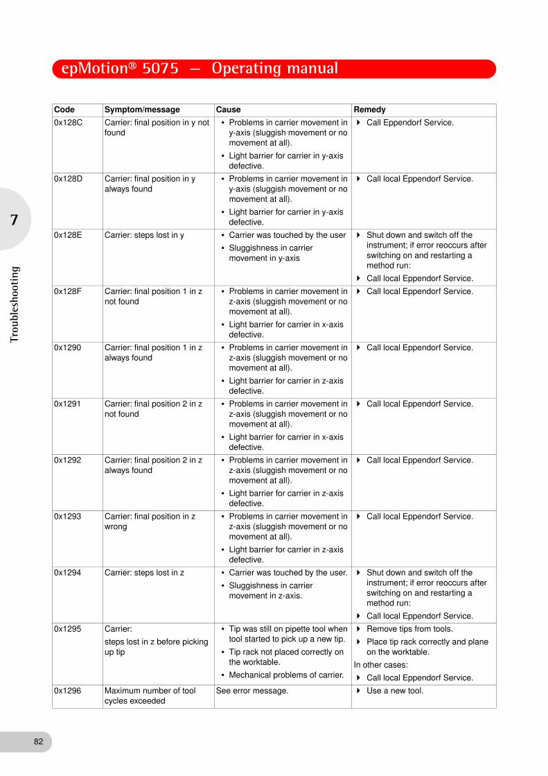
epMotion® 5075 — Operating manual
82
7
Trou
bles
hoot
ing
0x128C Carrier: final position in y not found
• Problems in carrier movement in y-axis (sluggish movement or no movement at all).
• Light barrier for carrier in y-axis defective.
Call Eppendorf Service.
0x128D Carrier: final position in y always found
• Problems in carrier movement in y-axis (sluggish movement or no movement at all).
• Light barrier for carrier in y-axis defective.
Call local Eppendorf Service.
0x128E Carrier: steps lost in y • Carrier was touched by the user
• Sluggishness in carrier movement in y-axis
Shut down and switch off the instrument; if error reoccurs after switching on and restarting a method run:
Call local Eppendorf Service.
0x128F Carrier: final position 1 in z not found
• Problems in carrier movement in z-axis (sluggish movement or no movement at all).
• Light barrier for carrier in x-axis defective.
Call local Eppendorf Service.
0x1290 Carrier: final position 1 in z always found
• Problems in carrier movement in z-axis (sluggish movement or no movement at all).
• Light barrier for carrier in z-axis defective.
Call local Eppendorf Service.
0x1291 Carrier: final position 2 in z not found
• Problems in carrier movement in z-axis (sluggish movement or no movement at all).
• Light barrier for carrier in x-axis defective.
Call local Eppendorf Service.
0x1292 Carrier: final position 2 in z always found
• Problems in carrier movement in z-axis (sluggish movement or no movement at all).
• Light barrier for carrier in z-axis defective.
Call local Eppendorf Service.
0x1293 Carrier: final position in z wrong
• Problems in carrier movement in z-axis (sluggish movement or no movement at all).
• Light barrier for carrier in z-axis defective.
Call local Eppendorf Service.
0x1294 Carrier: steps lost in z • Carrier was touched by the user.
• Sluggishness in carrier movement in z-axis.
Shut down and switch off the instrument; if error reoccurs after switching on and restarting a method run:
Call local Eppendorf Service.
0x1295 Carrier:
steps lost in z before picking up tip
• Tip was still on pipette tool when tool started to pick up a new tip.
• Tip rack not placed correctly on the worktable.
• Mechanical problems of carrier.
Remove tips from tools.
Place tip rack correctly and plane on the worktable.
In other cases:
Call local Eppendorf Service.
0x1296 Maximum number of tool cycles exceeded
See error message. Use a new tool.
Code Symptom/message Cause Remedy

epMotion® 5075 — Operating manual
7
Troubleshooting
0x1297 Danger of collision When running the programmed application, the tool carrier system will touch racks or other labware on the worktable; e.g., during pipetting the optical sensor may touch a long tube on the adjacent position; possible reasons:
• A low plate (microplate) is located next to a high tube rack.
• The 50 μL or 300 μL tip is programmed to move almost to the bottom of a very long tube with another long tube in the adjacent position.
Program the labware on the worktable in a way that high and low labware are not adjacent.
Program the labware in a way that the 30 μL or 300 μL tip does not have to move deeply into a long vessel.
If possible: use higher volumes in the long vessels.
If possible: use longer tips for the long vessels.
0x1298 Tool not calibrated The actual tool is not calibrated. Calibrate the actual tool.
0x1299 Invalid number of samples Value for Number of Samples not permissible.
Insert an admissible value for Number of Samples.
0x129A Tip too small Reagent Transfer: Used tip is too small.
Use a larger tip.
0x129B Source vessel too small Reagent Transfer: Used source vessel is too small.
Use a larger vessel.
0x12A0 Vacuum unit not ready Vacuum unit cannot be addressed by the software.
Call local Eppendorf Service.
0x12A1 Vacuum not released Ventilation of the vacuum unit after switching off the pump is too slow.
Call local Eppendorf Service.
0x12A2 Check levels in vacuum command:
Wells in filter plate not empty
Wells of the filter plate plug while applying vacuum.
Follow the instructions on the control panel display.
0x12A4 Labware in vacuum manifold is not composed of three parts (filter plate, frame, collection labware)
When applying vacuum three items must be in the vacuum unit (filter plate above vac frame above collection plate or tub).
See explanation in "Cause".
0x12A5 Well pattern of upper and lower rack do not fit
Vacuum unit: Well geometry of filter plate and collection plate must correspond to each other (e.g., 96 well filter plate and 96 well collection plate). Exception: Collection plate may be replaced by a tub.
See explanation in "Cause".
0x12B1 Temperature unit in location C1 not ready
Temperature unit 1 cannot be addressed by the software.
Call local Eppendorf Service.
0x12B2 Temperature unit in location C2 not ready
Temperature unit 2 cannot be addressed by the software.
Call local Eppendorf Service.
0x12B3 Temperature unit in location C3 not ready
Temperature unit 3 cannot be addressed by the software.
Call local Eppendorf Service.
0x12B4 Temperature unit in location C1 not active
In wait command the wait for temperature parameter was edited for location C1 although no temperature command for C1 had been edited before.
Insert temperature command before wait command or delete the wait for temperature parameter for this location.
0x12B5 Temperature unit in location C2 not active
In wait command the wait for temperature parameter was edited for location C2 although no temperature command for C2 had been edited before.
Insert temperature command before wait command or delete the wait for temperature parameter for this location.
Code Symptom/message Cause Remedy
83

epMotion® 5075 — Operating manual
84
7
Trou
bles
hoot
ing
0x12B6 Temperature unit in location C3 not active
In wait command the wait for temperature parameter was edited for location C3 although no temperature command for C3 had been edited before.
Insert temperature command before wait command or delete the wait for temperature parameter for this location.
0x12B7 Temperature unit in location C1 too hot for labware (temperature command in this method)
The temperature of location C1 (according to a temperature command in this application) is too high for the labware placed on this location.
Select a labware item that is more resistant to high temperatures (e.g. made from polypropylene or polycarbonate).
0x12B8 Temperature unit in location C2 too hot for labware (temperature command in this method)
The temperature of location C2 (according to a temperature command in this application) is too high for the labware placed on this location.
Select a labware item that is more resistant to high temperatures (e.g. made from polypropylene or polycarbonate).
0x12B9 Temperature unit in location C3 too hot for labware (temperature command in this method)
The temperature of location C3 (according to a temperature command in this application) is too high for the labware placed on this location.
Select a labware item that is more resistant to high temperatures (e.g. made from polypropylene or polycarbonate).
0x12BA Temperature unit in location C1 too hot for labware (temperature command in previous method)
The temperature of location C1 (according to a temperature command in a previous application with parameter keep temperature after method run set active) is too high for the labware placed on this location.
Select a labware item that is more resistant to high temperatures (e.g. made from polypropylene or polycarbonate).
Change previous application not to keep temperature after application run.
0x12BB Temperature unit in location C2 too hot for labware (temperature command in previous method)
The temperature of location C2 (according to a temperature command in a previous application with parameter keep temperature after method run set active) is too high for the labware placed on this location.
Select a labware item that is more resistant to high temperatures (e.g. made from polypropylene or polycarbonate).
Change previous application not to keep temperature after application run.
0x12BC Temperature unit in location C3 too hot for labware (temperature command in previous method)
The temperature of location C3 (according to a temperature command in a previous application with parameter keep temperature after method run set active) is too high for the labware placed on this location.
Select a labware item that is more resistant to high temperatures (e.g. made from polypropylene or polycarbonate).
Change previous application not to keep temperature after application run.
0x12D0 Parameter conflict:
Elution volume too large for this tool
Sample transfer with elution from filter option:
Volume to be aspirated is too large for the tip used.
Select a tip large enough for picking up the liquid as well as the additional volume of air to be aspirated when using this option.
0x12D1 Parameter conflict:
Elution volume too large for destination tube or well
Option elution from filter: volume is too large for the vessel used.
Select a tool large enough when using this option.
0x12E0 Error in system configuration Error in system configuration. Correct system configuration.
0x12E1 Parameter conflict:
Prewetting not possible when aspirate from bottom is selected
See error message. Change application.
Code Symptom/message Cause Remedy

epMotion® 5075 — Operating manual
7
Troubleshooting
0x12E2 Parameter conflict:
Prewetting not possible when dispense from top is selected
See error message. Change application.
0x12E3 Parameter conflict:
Prewetting not possible when elution from filter is selected
A liquid type using a prewetting step (e.g., ethanol 98%) cannot be used in combination with the elution from filter parameter in a sample transfer command.
Change application.
0x12E4 Transport of labware: danger of collision
Danger of collision when transporting a stack of several racks. The upper rack would collide with the carrier.
Do not pile more than 5 racks in a location.
0x12E6 Level too high The liquid level would be higher than the vessel after dispensing.
Adjust the liquid to be dispensed to the vessel.
0x12E7 Opening the hood is not allowed when putting down tool.
Switch off power, then switch on again to restart method.
See error message. See error message.
0x12F1 No communication with thermomixer
Hardware error
The thermomixer may be damaged.
Shut down and switch off the instrument; if error re-occurs after switching on: Call Eppendorf Service
0x12F3 Thermomixer is too hot for labware (temperature command in this method)
The temperature unit of the thermomixer is to hot for the selected labware
Choose a lower temperature
0x12F4 The thermomixer is too hot for labware (temperature command in previous method)
The temperature unit of the thermomixer is to hot for the selected labware
Choose a lower temperature
0x12F7 Waiting for thermomixer The procedure is waiting for the thermomixer.
Wait until thermomixer function has ended
0x12F8 The selected mixing speed is not possible with this labware
The mixing speed is not allowed for the selected labware
Select another labware or mixing speed
0x1500 Too big vessel index in location: ...
A tube is to be accessed for which the index is greater than the number of tubes on the plate/rack/holder.
Error during creation of the application.
0x1503 Tool not placed ... Optical sensor:
A tool that is needed for the application run was not found on the worktable.
Put the tool on the tool holder of the worktable.
0x1504 <rack name> is not accessible for tools in location ...
Rack is a lower part of a labware stack; therefore, the tool has no access.
Change application so that the rack is accessible.
0x1509 Liquid volume too large for vessel in location:...
Total volume supplied in a source vessel is larger than needed or larger than vessel.
Provide less volume in the vessel.
Change application.
When verifying the total volume needed for the source or destination, take into account additional aspirated volume in case of multidispense mode(see Important volume terms for tubes and wells on p. 24).
Code Symptom/message Cause Remedy
85

epMotion® 5075 — Operating manual
86
7
Trou
bles
hoot
ing
0x150A Liquid volume too low for vessel in location: ...
Total volume supplied by the user in a source vessel is smaller than needed for a sample transfer, reagent transfer or mix command (total volume = volume to be aspirated + remaining volume for this vessel + (in case of multidispense mode:) additional aspirated volume.
Calculate the total volume for the source or destination vessel and select a suitable vessel. Regarding additional aspirated volume in case of multidispense mode, refer to manual (see Important volume terms for tubes and wells on p. 24).
Consider that the software may calculate higher remaining volumes in some cases to avoid crashes.
Set liquid detection to off for racks that are on park positions at the beginning of the procedure.
0x150B Optical sensor:
Liquid volume too low in location: ...
See above (error 0x150A). See above (error 0x150A).
0x150D Optical sensor: Plate could not be found in location: ...
Optical sensor: Rack could not be found in location: ...
The rack programmed for this location could not be found by the optical sensor; possible causes:
• Rack not placed onto location (wrong rack code or wrong rack height).
• Rack in wrong orientation.
• Problems related to the optical sensor function.
Place the rack onto the locations as edited in the corresponding application; or:
Make sure that the rack is placed plane on the worktable surface; or:
Rotate rack 180° (front to back) and place it back onto the worktable location; or:
Call local Eppendorf Service.
0x150E Optical sensor:
Tips could not be found in location ...
The tip rack programmed for this location could not be found by the optical sensor; possible causes:
• Tip rack not placed onto location.
• Problems related to the optical sensor function.
Place the tip rack onto the locations as edited in the corresponding application; or:
Call local Eppendorf Service.
0x1510 Optical sensor: Nothing could be found in location:
See error message. Place the labware programmed for this location on the worktable.
If error occurs again:
Call local Eppendorf Service.
0x1512 Tip type ... is not placed on the worktable
Tips that are needed according to the application are not available on the worktable.
Place the tip tray programmed for this location on the worktable.
If error occurs again:
Call local Eppendorf Service.
0x1513 Position is out of range The position to be addressed by the tool carrier is outside of its available range.
Change application.
If error occurs again:
Call local Eppendorf Service.
0x1514 Optical sensor: Rack in wrong orientation in location ...
The tub holder has been placed onto the worktable in the wrong direction.
Rotate tub holder 180° and place it back onto the worktable; restart the application.
0x1515 Tool cannot be used for rack in location ...
Distance between tip cones of the liquid handling tool does not match the distance between vessels (e.g., 24 tubes - rack does not fit the 8-channel tool).
Change application.
Code Symptom/message Cause Remedy

epMotion® 5075 — Operating manual
7
Troubleshooting
0x1516 No vessel in location: ... Vessels that are needed according to the application are not available on the worktable (vessel/rack combination).
Place the vessel/rack combination programmed for this location on the worktable.
If error occurs again:
Call local Eppendorf Service.
0x1518 Rack is not tangible in location: ...
The item cannot be picked up by the gripper.
Change application.
0x1519 Tip is too thick for vessel in location: ...
Diameter of the destination vessel is too small for the tip when dispensing the liquid.
Select other tips or vessels in the application.
Select dispense from top in the options of the liquid handling command.
0x151A Optical sensor:
There is a cap on vessel in location: ...
The optical sensor has detected a cap on a vessel when trying to detect a liquid level.
Remove the cap from the vessel and start the run again.
0x151B Optical sensor: There is a wrong vessel in location: ...
Relates to vessels that are equipped with a readable code (e.g. Eppendorf tubs): The rack programmed for this location could not be found by the optical sensor; possible causes:
• Wrong vessel.
• Problems related to the optical sensor function.
Place the vessel onto the location as edited in the corresponding application; or:
Call local Eppendorf Application Support.
0x151C Optical sensor:
Vessel too high for level detection in location: ...
Level detection for very high vessels is not possible.
Switch off the level detection for this vessel.
Use level detection only for vessel/rack equipment with a total height below 103 mm.
0x151E Detected volume is out of detection range ...
Normally a system/hardware error (malfunction of the optical sensor); but may also be caused by filling a vessel up to the total vessel height.
Do not fill vessels above the specified maximum filling volume.
In other cases:
Call local Eppendorf Service.
0x151F Labware stack too high in location:
Maximum pieces which may be piled:
A maximum of 5 racks can be stacked in a location. Placing more than 5 racks in a location.
Do not stack more than 5 racks in a location.
0x1522 Transport of the selected labware to this position or stack is not allowed
Position xxx
Different reasons to forbid this transport; main reason: transport of the selected labware to this position or stack might result in instability of the stack, or the resulting stack might become too high.
Change application.
0x1523 Labware stack too high in location: xxx
Maximum height: xxx mm
Total height of labware stacks (like plates on adapters) is too high.
Edit application to avoid too high labware stacks.
0x1525 Filter plate wells are not empty
Using the check levels option in the vacuum command, the optical sensor detected residual liquid in one of the filter wells.
Follow the instructions on the display screen.
Code Symptom/message Cause Remedy
87

epMotion® 5075 — Operating manual
88
7
Trou
bles
hoot
ing
0x1526 No free position for deposition of tool available
When trying to deposit the dispensing tool after use the tool holder did not find a free position for the tool.
Clear at least one position on the worktable to accept a dispensing tool.
0x1528 Method program may not use more than four dispensing tools
See error message. If more than 4 dispensing tools are needed, divide the application into two applications that use no more than 4 dispensing tools.
0x1529 Dispensing tool could not be found.
Dispensing tool required for this method:...
See error message. Provide the dispensing tool that is needed on the worktable at its proper position.
0x152A Gripper could not be found See error message. Provide the gripper on the worktable at its proper position.
0x152D Tip too short
Select other tips or vessels in the method.
Tip does not reach the liquid level at the beginning or during the course of the liquid handling command.
Select other tips or vessels in the application.
0x152F Labware stack too high in location: xxx
Maximum pieces which may be piled: 5
A maximum of 5 racks can be piled in a location. After a transport command the labware stack would be too high.
Change application.
0x1530 Dosing in pile not allowed in location: xxx
See error message. Change application.
0x1531 Transport of this pile not allowed in location: xxx
Do not transport a stack. Change application.
0x1581 Optical sensor:
Liquid level could not be detected in location: ...
Error in level detection. Repeat measurement.
0x1600 Header not detected Cycler editor: Header command not detected. File damaged.
Call local Eppendorf Service.
0x1601 Load filename Command in the file is not a cycler command. File damaged.
Call local Eppendorf Service.
0x1602 Program too long Maximum size of steps (100) is reached.
Delete unnecessary commands before insert new commands.
0x1603 Load filename Cycler editor: End command not found. File damaged.
Call local Eppendorf Service.
0x1604 Load filename Parameters of a command are not loadable. File damaged.
Call local Eppendorf Service.
0x1700 Liquid volume too low for vessel in location: ...
Total volume supplied by the user in a source vessel is smaller than needed for a sample transfer, reagent transfer or mix command (total volume = volume to be aspirated + remaining volume for this vessel + (in case of multidispense mode:) additional aspirated volume.
Calculate the total volume for the source or destination vessel and select a suitable vessel. Regarding additional aspirated volume in case of multidispense mode, refer to manual (see Important volume terms for tubes and wells on p. 24).
Consider that the software may calculate higher remaining volumes in some cases to avoid crashes.
Set liquid detection to off for racks that are on park positions at the beginning of the procedure.
Code Symptom/message Cause Remedy

epMotion® 5075 — Operating manual
7
Troubleshooting
0x1701 Liquid volume too large for vessel in location:...
Total volume supplied in a source vessel is larger than needed or larger than vessel.
Provide less volume in the vessel.
Change application.
When verifying the total volume needed for the source or destination, take into account additional aspirated volume in case of multidispense mode(see Important volume terms for tubes and wells on p. 24).
0x1900 Program error/system error Internal program error. Restart application run or restart system.
If error occurs again:
Call local Eppendorf Service.
0x1901 Loading error File damaged. Call local Eppendorf Service.
0x1902 Loading error File damaged. Call local Eppendorf Service.
0x1903 Loading error File damaged. Call local Eppendorf Service.
0x1904 The following labware has been deleted: ...
Edit mode:
The worktable was changed after an application had been programmed; thus, the labware defined in a command is no longer available.
Change the source or destination in the parameter of the respective command in accordance to match the worktable. In this case the pattern also has to be re-edited;
The labware has to be reprogrammed in the worktable.
0x1905 Loading error File damaged. Call local Eppendorf Service.
0x1906 Loading error File damaged. Call local Eppendorf Service.
0x1907 Loading error File damaged. Call local Eppendorf Service.
0x1908 The method was written with a newer program structure. You must update your software if you want to edit this method
See Error message. Update your software, or:
Call local Eppendorf Service.
0x1909 Loading error File damaged. Call local Eppendorf Service.
0x190D The following labware is not selected in node epMotion: ...
Edit mode/worktable:
The chosen labware is not available in the labware collection that had been selected for your lab in the software node epMotion. Possible cause for this error message: The labware has been deselected in the epMotion node.
Set the respective labware in the epMotion node in order to select it. This node is accessible for the administrator only (if your lab runs the epMotion by using the "administrator" function).
0x190A Program error/system error Internal program error. Restart application run or restart system.
If error occurs again:
Call local Eppendorf Service.
0x190B Program error/system error Internal program error. Restart application run or restart system.
If error occurs again:
Call local Eppendorf Service.
Code Symptom/message Cause Remedy
89

epMotion® 5075 — Operating manual
90
7
Trou
bles
hoot
ing
0x190C Program error/system error Internal program error. Restart application run or restart system.
If error occurs again:
Call local Eppendorf Service.
0x190E The following tool is not selected in node epMotion: ...
Edit mode/procedure:
The chosen tool is not available in the labware collection that had been selected for your lab in the software node epMotion. Possible cause for this error message: The labware has been deselected in the epMotion”node.
Set the concerned labware in the node epMotion to “select”. This node is accessible for the administrator only (if your lab runs the epMotion by using the “administrator” function).
0x190F The following liquid is not selected in node epMotion: ...
Edit mode/procedure: The chosen liquid option is not available in the labware collection that had been selected for your lab in the software node epMotion. Possible cause for this error message: The labware has been deselected in the epMotion node.
Set the concerned labware in the node epMotion to “select”. This node is accessible for the administrator only (if your lab runs the epMotion by using the “administrator” function).
0x1910 The position of the following labware is not available on this worktable
The method was written for another workstation configuration
Edit mode/worktable: The chosen labware is not available in the labware collection that had been selected for your lab in the software node epMotion. Possible cause for this error message: The labware has been deselected in the epMotion node.
Set the respective labware in the node epMotion.
The position of the following labware is not allowed anymore
yyy
in location: xxx
Edit mode/worktable: The chosen labware may not be placed on the selected position anymore. Possible cause for this error message: The application has been written with a former version of the software.
Place the respective labware on another position.
0x1911 The following labware has been changed, so that the pattern does not fit anymore: xxx
Because you can change the order or contents Tubs + Modules(equip) + Holders combination, it can happen that the recent pattern of a command does not fit the new positions of the tubes.
Either change the order or contents of the Tubs + Modules(equip) + Holders combination back to the original. Or change the pattern in the command.
0x1980 to 0x1983
Program error/system error Internal program error. Restart application run or restart system.
If error occurs again:
Call local Eppendorf Service.
0x1984 No parameter for tool/liquid. Edit mode/parameter in command Sample Transfer:
A special file for the selected combination of tool and liquid type is not available.
Select another tool or another liquid type.
0x1985 Program error/system error Internal program error. Restart application run or restart system.
If error occurs again:
Call local Eppendorf Service.
Code Symptom/message Cause Remedy

epMotion® 5075 — Operating manual
7
Troubleshooting
0x1986 Program error/system error Internal program error. Restart application run or restart system.
If error occurs again:
Call local Eppendorf Service.
0x1A00 Program error/system error Internal program error. Restart application run or restart system.
If error occurs again:
Call local Eppendorf Service.
0x1A01 Program error/system error Internal program error. Restart application run or restart system.
If error occurs again:
Call local Eppendorf Service.
0x1A02 The name is already used for another labware.
Edit mode/labware: The same name has been defined for a different rack or another labware item.
Enter a different name.
0x1A02 The name is already used for another labware
Edit mode / labware:
The same name has been defined for a different rack or another labware item.
Enter a different name.
0x1A03 This position is not available for the selected labware
Edit mode/worktable:
Certain worktable positions are not allowed for certain labware (e.g., tips can only be placed in the rear of the worktable).
Place the selected labware in another location.
0x1A04 The selected labware may not be stacked on top of labware already placed
Edit mode/worktable:
Building of labware stacks on the worktable is restricted to certain labware combinations (e.g., thermorack above thermorack does not make sense).
See "Cause".
0x1A05 Maximum number of labware stacked: 5
Edit mode/worktable:
Certain labware build a pile which contains too many when placed on certain labware.
Place the selected labware in another location.
0x1A06 Labware stack too high in location: xxx
Maximum height: xxx mm
Edit mode/worktable:
Labware stacks on the worktable may not exceed a maximum height limit (e.g., plates on adapters is allowed; reservoir holder on adapters is not allowed because the stack would become too high).
See "Cause".
0x1A10 8-channel tool cannot be used for this source rack
Edit mode/parameter in command Sample Transfer:
Source rack does not fit the 8-channel tool (e.g., 24-well plate or tube rack with 24 positions).
Choose another rack or another tool.
0x1A11 8-channel tool cannot be used for this destination rack.
Edit mode/parameter in command Sample Transfer:
Destination rack does not fit the 8-channel tool (e.g. 24-well plate or tube rack with 24 positions).
Choose another rack or another tool.
Code Symptom/message Cause Remedy
91

epMotion® 5075 — Operating manual
92
7
Trou
bles
hoot
ing
0x1A12 No source or destination selected
Edit mode/parameter in command Sample Transfer:
Source or destination rack has not been selected.
Select source or destination, respectively.
0x1A13 Program error/system error Internal program error. Restart application run or restart system.
If error occurs again:
Call local Eppendorf Service.
0x1A14 Program error/system error Internal program error. Restart application run or restart system.
If error occurs again:
Call local Eppendorf Service.
0x1A15 Invalid entry for movement blow (0 ... 100)
Edit mode/parameter in transfer command:
A value beyond the allowed range has been entered for the parameter movement blow.
Enter a value between 0 and 100%.
0x1A16 Invalid entry for delay blow (0 ... 9999)
Edit mode/parameter in transfer command:
A value beyond the allowed range has been entered for the parameter Delay Blow.
Enter a value between 0 and 9999 msec.
0x1A17 Invalid entry for speed aspiration (0.2 ... 110)
Edit mode/parameter in transfer command:
A value beyond the allowed range has been entered for the parameter Speed Aspiration.
Enter a value between 0.2 and 110 mm/sec.
0x1A18 Invalid entry for speed dispense (0.2 ... 110)
Edit mode/parameter in transfer command:
A value beyond the allowed range has been entered for the parameter Speed Dispense.
Enter a value between 0.2 and 110 mm/sec.
0x1A18 Invalid entry for speed dispense (0.2 ... 110)
Edit mode/parameter in transfer command:
A value beyond the allowed range has been entered for the parameter Speed Dispense.
Enter a value between 0.2 and 110 mm/sec.
0x1A19 Invalid entry for speed blow (0.2 ... 110)
Edit mode/parameter in transfer command:
A value beyond the allowed range has been entered for the parameter Speed Blow.
Enter a value between 0.2 and 110 mm/sec.
0x1A1A Invalid entry for initial stroke (0 ... 100)
Edit mode/parameter in transfer command: a value beyond the allowed range has been entered for the parameter initial stroke.
Enter a value between 0 and 100%.
0x1A20 8-channel tool cannot be used for this source rack
Edit mode/parameter in command Reagent Transfer:
Source rack does not fit the 8-channel tool (e.g., 24-well plate or tube rack with 24 positions).
Choose another rack or another tool.
Code Symptom/message Cause Remedy

epMotion® 5075 — Operating manual
7
Troubleshooting
0x1A21 8-channel tool cannot be used for this destination rack
Edit mode/parameter in command Reagent Transfer:
Destination rack does not fit the 8-channel tool (e.g., 24-well plate or tube rack with 24 positions).
Choose another rack or another tool.
0x1A22 No source or destination selected
Edit mode/parameter in command Reagent Transfer:
Source or destination rack has not been selected.
Select source or destination, respectively.
0x1A23 Program error/system error Internal program error. Restart application run or restart system.
If error occurs again:
Call local Eppendorf Service.
0x1A24 Program error/system error Internal program error. Restart application run or restart system.
If error occurs again:
Call local Eppendorf Service.
0x1A30 8-channel tool cannot be used for this source rack
Edit mode/parameter in command Pool:
Source rack does not fit the 8-channel tool (e.g., 24-well plate or tube rack with 24 positions).
Choose another rack or another tool.
0x1A31 8-channel tool cannot be used for this destination rack
Edit mode/parameter in command Pool:
Destination rack does not fit the 8-channel tool (e.g. 24-well plate or tube rack with 24 positions).
Choose another rack or another tool.
0x1A32 No source or destination selected
Edit mode/parameter in command Pool:
Source or destination rack has not been selected.
Select source or destination, respectively.
0x1A40 8-channel tool cannot be used for this source rack
Edit mode/parameter in command PoolOneDest:
Source rack does not fit the 8-channel tool (e.g., 24-well plate or tube rack with 24 positions).
Choose another rack or another tool.
0x1A41 8-channel tool cannot be used for this destination rack
Edit mode/parameter in command PoolOneDest:
Destination rack does not fit the 8-channel tool (e.g. 24-well plate or tube rack with 24 positions).
Choose another rack or another tool.
0x1A42 No source or destination selected
Edit mode/parameter in command PoolOneDest:
Source or destination rack has not been selected.
Select source or destination, respectively.
0x1A50 8-channel tool cannot be used for this source rack
Edit mode/parameter in command Dilute:
Source rack does not fit the 8-channel tool (e.g., 24-well plate or tube rack with 24 positions).
Choose another rack or another tool.
Code Symptom/message Cause Remedy
93

epMotion® 5075 — Operating manual
94
7
Trou
bles
hoot
ing
0x1A51 8-channel tool cannot be used for this destination rack
Edit mode/parameter in command Dilute:
Destination rack does not fit the 8-channel tool (e.g. 24-well plate or tube rack with 24 positions).
Choose another rack or another tool.
0x1A52 No source or destination selected
Edit mode/parameter in command Dilute:
Source or destination rack has not been selected.
Select source or destination, respectively.
0x1A60 Program error/system error Internal program error. Restart application run or restart system.
If error occurs again:
Call local Eppendorf Service.
0x1A61 8-channel tool cannot be used for this rack
Edit mode/parameter in command Mix:
Rack does not fit the 8-channel tool (e.g., 24-well plate or tube rack with 24 positions).
Choose another rack or another tool.
0x1A62 No rack selected Edit mode/parameter in command Mix:
Rack has not been selected.
Select rack, respectively.
0x1A63 Program error/system error Internal program error. Restart application run or restart system.
If error occurs again:
Call local Eppendorf Service.
0x1A64 Program error/system error Internal program error. Restart application run or restart system.
If error occurs again:
Call local Eppendorf Service.
0x1A65 Invalid entry for speed (0.2 ... 110)
Edit mode/parameter in command Mix:
A value beyond the allowed range has been entered for the parameter Speed .
Enter a value between 0.2 and 110 mm/sec.
0x1A70 This position is already occupied
Edit mode/pattern:
When editing the pattern you have tried to select a certain position that is already occupied.
Follow the direction of the edited pattern and move to a different position.
0x1A71 Program error/system error Internal program error. Restart application run or restart system.
If error occurs again:
Call local Eppendorf Service.
0x1A72 Memory insufficient. Edit mode/pattern:
Not enough software memory available for editing the pattern.
Save application and restart system; if error occurs again try to reduce the amount of commands, if possible.
In case this is not possible:
Call local Eppendorf Application Support.
Code Symptom/message Cause Remedy

epMotion® 5075 — Operating manual
7
Troubleshooting
0x1A73 Delete function only available for last entry
Edit mode/pattern:
You may only delete a pattern position that you just entered as long as you did not leave the source (or the destination, respectively).
If you have to delete this position which is no longer available you must edit a new pattern from the beginning (softkey New pat. or Cancel).
0x1A74 Memory insufficient. Edit mode/pattern:
Not enough software memory available for editing the pattern.
Save application and restart system; if error occurs again try to reduce the amount of commands, if possible.
In case this is not possible:
Call local Eppendorf Service.
0x1A75 A rack may only have 384 positions
Edit mode/pattern:
Not enough software memory available for editing the pattern. Maximum possible positions are 384.
Choose another rack, because the chosen rack has too many positions.
0x1A76 8-channel tool cannot be used for this module rack
Edit mode/pattern:
Rack does not fit the 8-channel tool (e.g., Tubs + Modules (equip) + Holders-combination with positions all less than 8 in Modules).
Choose another rack or another tool.
0x1A77 No module rack or tubes found
Edit mode/pattern:
Rack does not have any positions (e.g., Tubs + Modules (equip) + Holders-combination with positions all less than 1 in Modules).
Choose another rack.
0x1A78 Number of tubes not supported
Edit mode/pattern:
One or more Modules have 3, 5, 6, 7 or more than 8 positions. This is not supported.
Choose another rack.
0x1A80 Invalid entry for minutes (0 ... 99)
Edit mode/parameter in command Wait:
A value beyond the allowed range has been entered for the parameter minutes.
Enter a value between 0 and 99 minutes.
0x1A81 Invalid entry for seconds (0 ... 59)
Edit mode/parameter in command Wait:
A value beyond the allowed range has been entered for the parameter seconds.
Enter a value between 0 and 59 seconds.
0x1A90 Selecting more than one rack as Source or as Destination:
All source racks (or all destination racks, resp.) must have the same well pattern
Edit mode/parameter in transfer command:
If more than one rack is selected as source (or destination) all source (or destination), racks must have the same well pattern (e.g. 96-well plates).
See explanation in "Cause".
0x1A91 Selecting more than one rack as Source or as Destination:
Rack was already selected as source rack (or as destination rack, resp.)
Edit mode/parameter in transfer command:
When editing more than one rack as source (or destination, respectively.) the same rack was selected twice.
Select different racks for editing more than one rack as source (or destination).
Code Symptom/message Cause Remedy
95

epMotion® 5075 — Operating manual
96
7
Trou
bles
hoot
ing
0x1AA0 Invalid entry for temperature (0 ... 110)
Edit mode/parameter in command Temperature:
A value beyond the allowed range has been entered for the parameter Temperature.
Enter a value between 0 and 110 degrees.
0x1AB0 Invalid entry for minutes (0 ... 99)
Edit mode/parameter in command Vacuum:
A value beyond the allowed range has been entered for the parameter minutes.
Enter a value between 0 and 99 minutes.
0x1AB1 Invalid entry for seconds (0 ... 59)
Edit mode/parameter in command Vacuum:
A value beyond the allowed range has been entered for the seconds parameter.
Enter a value between 0 and 59 seconds.
0x1AB2 Invalid entry for vacuum pressure (1 ... 90) kPa and (10 ... 900) mbar resp.
Edit mode/parameter in command Vacuum:
A value beyond the allowed range has been entered for the seconds parameter.
Enter a value between 0 and 59 seconds.
0x1AC1 Program error/system error Internal program error. Restart application run or restart system.
If error occurs again:
Call local Eppendorf Service.
0x1AE0 Invalid entry for mixing speed (0 ... 2000)
Edit mode / parameter in command ”Thermomixer”: a value beyond the allowed range has been entered for the parameter ”speed”
Enter a value between 0 and 2000 rpm
0x1AE1 Invalid entry for minutes (0 ... 120)
Edit mode / parameter in command ”Thermomixer”: a value beyond the allowed range has been entered for the parameter ”minutes”
Enter a value between 0 and 120 minutes
0x1AE2 Invalid entry for seconds (0 ... 59)
Edit mode / parameter in command ”Thermomixer”: a value beyond the allowed range has been entered for the parameter ”seconds”
Enter a value between 0 and 59 seconds
0x1AE3 Invalid entry for temperature (4 ... 110)
Edit mode / parameter in command ”Thermomixer”: a value beyond the allowed range has been entered for the parameter ”temperature”
Enter a value between 4 and 110 degrees
0x1C00 to 0x1C09
File could not be read File damaged. Call local Eppendorf Service.
0x1C0B Sample number too large Run mode:
The number of samples you entered will fill more than one rack (source or destination, respectively) based on the programmed pattern.
Start the application again and enter a lower number of samples; or:
Enter the edit mode and program a pattern that together with the number of samples you want to run will not extend beyond one rack.
0x1C0C File could not be read File damaged. Call local Eppendorf Service.
0x1C0D You must clear old pattern first
Press new pattern
Edit mode/pattern:
You tried to change a stored pattern before deleting the old pattern.
Delete the old pattern by pressing the New pat. softkey
Code Symptom/message Cause Remedy

epMotion® 5075 — Operating manual
7
Troubleshooting
0x1C0E You must go forward Edit mode/pattern:
When entering the pattern, the order of edited locations in the source (or destination, respectively) must be from left to right or from the top of the pattern downwards (i.e., move only in columns or in rows).
See explanation in "Cause".
0x1C0F You may only move horizontally or vertically
Edit mode/pattern:
When entering the pattern the order of edited locations in the source (or destination, resp.) must be from the left to right or from top of the pattern downwards (i.e., move only in columns or in rows).
Note: Error message may also occur when working with an 8-channel tool and editing another position than the upper ones (see error code 0x1C1F).
See explanation in "Cause".
0x1C10 Pattern for replicates of first sample too complex
Edit mode/pattern:
The pattern algorithm cannot handle this pattern.
Enter a simpler pattern if possible.
In case this is not possible:
Call local Eppendorf Application Support.
0x1C11 Pattern too complex Edit mode/pattern:
The pattern algorithm cannot handle this pattern.
Note: See note in error 0x1C0F.
Enter a simpler pattern if possible.
In case this is not possible:
Call local Eppendorf Application Support.
0x1C12 Program error/system error Internal program error. Restart application run or restart system.
If error occurs again:
Call local Eppendorf Service.
0x1C13 Program error/system error Internal program error. Restart application run or restart system.
If error occurs again:
Call local Eppendorf Service.
0x1C14 Pattern must fit in rows or columns
Edit mode/pattern:
The basic unit of the pattern you tried to enter extends beyond a row or a column. This cannot be handled by the pattern algorithm.
Enter a simpler pattern if possible.
In case this is not possible:
Call local Eppendorf Application Support.
0x1C15 Pattern too complex Edit mode/pattern:
The pattern algorithm cannot handle this pattern.
Note: See note in error 0x1C0F.
Enter a simpler pattern if possible.
In case this is not possible:
Call local Eppendorf Service.
0x1C16 This position is already occupied
Edit mode/pattern:
When editing the pattern you have tried to select a certain rack position that is already occupied.
Following the edited pattern move to a different rack position.
0x1C17 You must start with the source
Edit mode/pattern:
When editing a pattern you must start with the source.
See explanation in "Cause".
Code Symptom/message Cause Remedy
97

epMotion® 5075 — Operating manual
98
7
Trou
bles
hoot
ing
0x1C18 Please enter a source now Edit mode/pattern:
In the destination rack, you tried to enter more replicates than you had sources.
Enter the same number of replicates for all sources you edit when programming a pattern.
0x1C19 Please enter a destination now
Edit mode/pattern:
When having selected a source in the Sample Transfer command you first have to enter a destination for this source before moving to the next source position.
Press the Destination softkey and edit the destination position(s) for the selected source position.
0x1C1A No more positions available (limited by Number of Samples command)
Edit mode/pattern:
Editing further positions is not possible because the limit set in the Number of Samples command would be exceeded.
Select a pattern that fits the programmed Number of Samples command.
0x1C1B Program error/system error Internal program error. Restart application run or restart system.
If error occurs again:
Call local Eppendorf Service.
0x1C1C Program error/system error Internal program error. Restart application run or restart system.
If error occurs again:
Call local Eppendorf Service.
0x1C1D Program error/system error Internal program error. Restart application run or restart system.
If error occurs again:
Call local Eppendorf Service.
0x1C1E Pattern for reagent transfer:
source can be chosen only once
Edit mode/pattern for command Reagent Transfer:
After having entered the source and the destinations for the reagent transfer you cannot select an additional source.
Enter the source only once. In case this does not meet your requirements for this application consider selecting command Sample Transfer instead of Reagent Transfer; or:
Call local Eppendorf Application Support.
0x1C1F Pattern with 8-channel tool:
Please edit upper position of this tool
Edit mode/pattern with 8-channel tool:
Only the upper positions of the 8-channel tools can be selected.
See explanation in "Cause".
0x1C20 Pattern for sample transfer:
only one position per sample on source
Edit mode/pattern for command Sample Transfer:
Before selecting a second source position, you have to edit the destination for the first source position.
Enter destination for the source you just selected; afterwards, you can edit the next source position.
0x1C21 In source rack further positions cannot be edited because positions in destination rack are already occupied
Edit mode/pattern:
Selecting further source positions would require a second destination rack according to the pattern you edited.
Edit a pattern that does not require more than one destination rack per command. To use more destination racks, create additional commands.
Code Symptom/message Cause Remedy
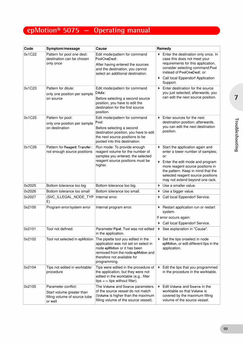
epMotion® 5075 — Operating manual
7
Troubleshooting
0x1C22 Pattern for pool one dest: destination can be chosen only once
Edit mode/pattern for command PoolOneDest:
After having entered the sources and the destination, you cannot select an additional destination.
Enter the destination only once. In case this does not meet your requirements for this application, consider selecting command Pool instead of PoolOneDest; or:
Call local Eppendorf Application Support.
0x1C23 Pattern for dilute:
only one position per sample on source
Edit mode/pattern for command Dilute:
Before selecting a second source position, you have to edit the destination for the first source position.
Enter destination for the source you just selected; afterwards, you can edit the next source position.
0x1C25 Pattern for pool:
only one position per sample on destination
Edit mode/pattern for command Pool:
Before selecting a second destination position, you have to edit the next source positions to be pooled into this destination.
Enter sources for the next destination position; afterwards, you can edit the next destination position.
0x1C26 Pattern for Reagent Transfer: not enough source positions
Run mode: To provide enough reagent volume for the number of samples you entered, the selected reagent source positions must be higher.
Start the application again and enter a lower number of samples; or:
Enter the edit mode and program more reagent source positions in the pattern. Keep in mind that the selected reagent source positions may not extend beyond one rack.
0x2025 Bottom tolerance too big Bottom tolerance too big. Use a smaller value.
0x2026 Bottom tolerance too small Bottom tolerance too small. Use a bigger value.
0x2027 (SVC_ILLEGAL_NODE_TYPE)
Internal error. Call local Eppendorf Service.
0x2100 Program error/system error Internal program error. Restart application run or restart system.
If error occurs again:
Call local Eppendorf Service.
0x2101 Tool not defined. Parameter Pipet. Tool was not edited in the application.
See explanation in "Cause".
0x2102 Tool not selected in epMotion The pipette tool you edited in the application was not set on select in node epMotion or it has been removed from the node epMotion and therefore not available for programming.
Set the tips onselect in node epMotion, or edit different tips in the application.
0x2104 Tips not edited in worktable/procedure
Tips were edited in the procedure of the application, but they were not edited in the worktable (e.g., filter tips <-> tips without filter).
Edit the tips that you programmed in the procedure in the worktable.
0x2105 Parameter conflict:
Start volume greater than filling volume of source tube or well
The Volume and Source parameters of the source vessel do not match (Volume is higher than the maximum filling volume of the source vessel).
Edit Volume and Source in the worktable so that Volume is covered by the maximum filling volume of the source vessel.
Code Symptom/message Cause Remedy
99

epMotion® 5075 — Operating manual
100
7
Trou
bles
hoot
ing
0x2106 Parameter conflict: Start volume greater than filling volume of destination tube or well
The Volume and Destination parameters of the destination vessel do not match (Volume is higher than the maximum filling volume of the destination vessel).
Edit Volume and Destination in the worktable so that Volume is covered by the maximum filling volume of the destination vessel.
0x2107 Volume not defined Parameter Volume was not edited in the application.
See explanation in "Cause".
0x2108 Parameter conflict:
Volume too small for this tool
The Volume and Pipet. Tool parameters of the application do not match (Volume is smaller than the lower limit of the tool volume range).
Edit Volume and Pipet. Tool so that Volume is covered by the volume range of the pipette tool.
0x2109 Parameter conflict:
Volume too large for this tool
The Volume and Pipet. Tool parameters of the application do not match (Volume is higher than the upper limit of the tool volume range).
Edit Volume and Pipet. Tool so that Volume is covered by the volume range of the pipette tool.
0x210A Parameter conflict: volume greater than filling volume of source tube or well
The Volume and Source parameters of the application do not match (Volume is higher than the maximum filling volume of the source vessel).
Edit Volume and Source so that Volume is covered by the maximum filling volume of the source vessel.
0x210B Parameter conflict:
volume greater than filling volume of destination tube or well
The Volume and Destination parameters of the application do not match (Volume is higher than the maximum filling volume of the destination vessel).
Edit Volume and Destination so that Volume is covered by the maximum filling volume of the destination vessel.
0x210D Source rack not defined Parameter Source was not edited in the application.
See explanation in "Cause".
0x210E Source rack not edited in worktable
The source rack you edited in the procedure of the application has been removed from the worktable.
Edit the rack that you programmed in the procedure as Source in the worktable, or edit a different source rack in the application.
0x210F Source rack not selected in epMotion
The source rack you edited in the application is not set on select in node epMotion, or it has been removed from the node epMotion and therefore is not available for programming.
Set the rack on select in node epMotion, or edit a different rack in the application.
0x2110 Destination rack not defined Parameter Source was not edited in the application.
See explanation in "Cause".
0x2111 Destination rack not edited in worktable
Destination rack was edited in the procedure of the application, but it was not edited in the worktable.
Edit the rack that you programmed in the procedure as Destination in the worktable or edit a different destination rack in the application.
0x2112 Destination rack not selected in epMotion
The destination rack you edited in the application is not set on select in node epMotion, or it has been removed from the node epMotion and therefore not available for programming.
Set the rack on select in node epMotion, or edit a different rack in the application.
0x2113 Pattern not defined Parameter Pattern was not edited in the application.
See explanation in "Cause".
0x2114 Loading error (invalid entry in pattern)
Normally a system error; but may also be caused by editing a pattern without destination positions; or:
File damaged.
Edit a pattern with source and destination positions.
In other cases:
Call local Eppendorf Service.
Code Symptom/message Cause Remedy

epMotion® 5075 — Operating manual
7
Troubleshooting
0x211B Liquid type not defined Parameter Liquid Type was not edited in the application (can be edited via the button Options in the parameter display).
See explanation in "Cause".
0x211C Liquid type not selected in epMotion
The Liquid Type you edited in the application is not set on select in node epMotion, or it has been removed from the node epMotion and therefore not available for programming (it can be edited via the Options button in the parameter display).
Set the liquid on select in node epMotion or edit a different liquid in the application.
0x211D Mixing cycles in source not defined
Parameter No. of Cycles in a mix procedure was not edited for the source in the application (mix procedure as defined in a command Mix or as part of a liquid transfer command via parameter Options).
See explanation in "Cause".
0x211E Invalid entry for mixing cycles in source (1 ... 99)
Entry for the No. of Cycles parameter in a mix procedure for source vessels was higher than the max. limit (1 up to 99 cycles) (mix procedure as defined in a command Mix or as part of a liquid transfer command via parameter Options).
Enter a number between 1 and 99 for the No. of Cycles parameter.
0x211F Invalid entry for mixing speed in source (1 ... 10)
Entry for the parameter Speed in a mix procedure for source vessels was higher than the max. limit (1 up to 10) (mix procedure as defined in a command Mix or as part of a liquid transfer command via parameter Options).
Enter a number between 1 and 10 for the Speed parameter.
0x2120 Mixing volume in source not defined
Parameter Volume in a mix procedure for source vessels was not edited in the application (mix procedure as defined in a command Mix or as part of a liquid transfer command via parameter Options).
See explanation in "Cause".
0x2121 Parameter conflict: mixing volume in source too large for this tool
The Volume and Pipet. Tool parameters of a mix procedure for source vessels are not in agreement (Volume is higher than the upper limit of the tool's volume range) (mix procedure as defined in a command Mix or as part of a liquid transfer command via parameter Options).
Edit Volume and Pipet. Tool so that Volume is within pipette tool's volume range.
0x2122 Parameter conflict: mixing volume in source too small for this tool
The Volume and Pipet. Tool parameters of a mix procedure for source vessels do not match (Volume is less than the lower limit of the tool's volume range) (mix procedure as defined in a command Mix or as part of a liquid transfer command via parameter Options).
Edit Volume and Pipet. Tool so that Volume is within the pipette tool's volume range.
Code Symptom/message Cause Remedy
101

epMotion® 5075 — Operating manual
102
7
Trou
bles
hoot
ing
0x2123 Parameter conflict:
mixing volume in source greater than filling volume of source tube or well
The Volume and Source parameters of a mix procedure in the application do not match (Volume is higher than the maximum filling volume of the source vessel) (mix procedure as defined in a command Mix or as part of a liquid transfer command via parameter Options).
Edit Volume and Source so that Volume is within the allowable filling volume of the source vessel.
0x2124 Mixing cycles in destination not defined
Parameter No. of Cycles in a mix procedure for destination vessels was not edited in the application (mix procedure as part of a liquid transfer command via parameter Options)
See explanation in "Cause".
0x2125 Invalid entry for mixing cycles in destination (1 ... 99)
Entry for the parameter No. of Cycles in a mix procedure for destination vessels was higher than the max. limit (1 up to 99 cycles) (mix procedure as part of a liquid transfer command via parameter Options).
Enter a number between 1 and 99 for the No. of Cycles parameter.
0x2126 Invalid entry for mixing speed in destination (1 ... 10)
Entry for the parameter Speed in a mix procedure for destination vessels was higher than the max. limit (1 up to 10) (mix procedure as part of a liquid transfer command via parameter Options).
Enter a number between 1 and 10 for the Speed parameter.
0x2127 Mixing volume in destination not defined
Parameter Volume in a mix procedure for destination vessels was not edited in the application (mix procedure as part of a liquid transfer command via parameter Options).
See explanation in "Cause".
0x2128 Parameter conflict:
mixing volume in destination too large for this tool
The Volume and Pipet. Tool parameters in a mix procedure for destination vessels do not match (Volume is higher than the upper limit of the tool volume range) (mix procedure as part of a liquid transfer command via parameter Options).
Edit Volume and Pipet. Tool so that Volume is within the pipette tool's volume range.
0x2129 Parameter conflict: mixing volume in destination too small for this tool
The Volume and Pipet. Tool in a mix procedure for destination vessels do not match (Volume is lower than the minimum allowed volume) (mix procedure as part of a liquid transfer command via parameter Options).
Edit Volume and Pipet. Tool so that Volume is within the volume range of the pipet tool.
0x212A Parameter conflict: mixing volume in destination greater than filling volume of destination tube or well
The Volume and Destination parameters in a mix procedure for destination vessels do not match (Volume is higher than the maximum filling volume of the destination vessel) (mix procedure as part of a liquid transfer command via parameter Options).
Edit Volume and Destination so that Volume is within the maximum filling volume of the destination vessel.
Code Symptom/message Cause Remedy

epMotion® 5075 — Operating manual
7
Troubleshooting
0x212C Parameter conflict:
mix after dispense not allowed in multidispense mode
When the transfer type parameter is set to multidispense, the mix after dispense parameter cannot be edited for this command.
Change parameter transfer type to pipette; or:
Omit the mixing step; in this case you could also edit another mixing step as a new command (Mix), which would be performed after the previous command of the procedure has ended.
0x212D Parameter conflict:
8-channel tool cannot be used for this source rack
Edit mode / parameter in liquid handling command:
Source rack does not fit the 8-channel tool (e.g., 24-well plate or tube rack with 24 positions).
Choose another rack or another tool.
0x212E Parameter conflict: 8-channel tool cannot be used for this destination rack
Edit mode / parameter in liquid handling command:
Destination rack does not fit the 8-channel tool (e.g. 24-well plate or tube rack with 24 positions).
Choose another rack or another tool.
0x212F Sample number too large The number of samples you have entered will fill more than one rack (source or destination, respectively) based on the programmed pattern.
Program a pattern that together with the number of samples you want to run will not extend beyond one rack, or choose a lower number of samples in the corresponding Number of Samples command.
0x2130 Parameter conflict: tip cannot be used for this source rack
The Source rack parameter in the liquid handling command does not match the selected tool (e.g., 384-well plate and TS_1000 or TM1000_8).
Choose another rack or another tool.
0x2131 Parameter conflict: tip cannot be used for this destination rack
The Destination rack parameter in the liquid handling command does not match the selected tool (e.g., 384-well plate and TS_1000 or TM1000_8).
Choose another rack or another tool.
0x2132 Invalid number of samples (1 ... 384)
Number of samples you have entered is too high.
Enter a maximum number of samples up to 384.
0x2133 Rack or plate not defined Edit mode/parameter in command Transport:
Labware to be transported was not edited.
See explanation in "Cause".
0x2134 Rack not selected in epMotion
The rack you edited in a command Transport (parameter labware) was not set on select in node epMotion and therefore is not available for programming.
Set the rack on select in node epMotion or edit a different rack in the application.
0x2135 Location for destination not defined
Edit mode/parameter in command Transport:
The destination location for the labware to be transported was not edited.
See explanation in "Cause".
Code Symptom/message Cause Remedy
103

epMotion® 5075 — Operating manual
104
7
Trou
bles
hoot
ing
0x2136 Invalid entry for seconds (1 ... 59)
Edit mode/parameter in command Wait:
A value beyond the allowed range has been entered for the seconds parameter.
Enter a value between 0 and 59 seconds.
0x2137 Invalid entry for minutes (1 ... 99)
Edit mode/parameter in command Wait:
A value above the allowable maximum minutes has been entered for the minutes parameter.
Enter a value between 0 and 99 minutes.
0x2138 Method without active commands
application contains only passive commands (like wait, comment, etc.).
Insert at least one active command.
0x2139 Parameter conflict:
mix before aspirating not allowed in multiaspirate mode
Pool/POD:
Mix before aspirating not allowed in multiaspirate mode.
Do not mix.
0x213A Labware to be exchanged are identical
Parameter in command Exchange:
Both values point to the same labware.
Enter a new labware for one of the two positions.
0x2150 Editing vacuum command not possible because vacuum unit is not part of this instrument
Vacuum unit is not listed in the configuration file.
Call local Eppendorf Service.
0x2151 Editing vacuum command not possible because no vacuum unit on the worktable
The worktable of this application does not contain a vacuum unit. Communication between instrument and control panel may be defective.
Call local Eppendorf Service.
0x2152 Editing vac lid option in vacuum command not possible because no vac lid on the worktable
To use the Vac Lid option in the vacuum command the worktable must be equipped with a vac lid.
Editing the worktable please place a Vac Lid on position "GRIPPER".
0x2153 Editing vac lid option vacuum command not possible because no gripper on the worktable
To use the Vac Lid option in the vacuum command the worktable must be equipped with a gripper. Communication between instrument and control panel may be defective.
Call local Eppendorf Service.
0x2154 Parameter conflict:
Check levels time may not be shorter than remove lid time
The check levels option can only be performed when the lid has been taken off the filter plate before by the gripper.
Select a check levels time greater than the remove lid time.
0x2160 No temperature unit in the selected location
Editing a temperature command you must select a location equipped with a temperature unit.
See explanations in "Cause".
0x2161 Temperature unit 1 is not installed
Temperature unit 1 is not listed in the configuration file.
Call local Eppendorf Service.
0x2162 Temperature unit 2 is not installed
Temperature unit 2 is not listed in the configuration file.
Call local Eppendorf Service.
0x2163 Temperature unit 3 is not installed
Temperature unit 3 is not listed in the configuration file.
Call local Eppendorf Service.
Code Symptom/message Cause Remedy

epMotion® 5075 — Operating manual
7
Troubleshooting
0x2170 Parameter conflict:
Parameter elution from filter is only possible when filter plates have been selected as source
To edit the elution from filter option a filter plate must have been edited as source.
See explanations in "Cause".
0x2171 Parameter conflict:
Multidispense mode is not allowed when selected elution from filter
See explanation in the error message.
See explanation in the error message.
0x2172 Parameter conflict:
Transfer volume must be set to zero when Parameter elution from filter has been selected
Using the elution from filter option, the complete volume contained in the filter plate wells is always aspirated; therefore, editing a volume to be transferred is not possible.
Set the volume to zero because the entry will not have an effect in the application run.
0x2173 Elution from filter is only possible in a sample transfer
File damaged. Call local Eppendorf Service.
0x2190 Transport command not possible because no workstation available
The chosen application may not be run on the selected device. Possible cause for this error message:
The application has been written for another device.
Load the concerned application on an other device, or
delete Transport commands in the application.
0x2191 Exchange command not possible because no liquid handling station available
The chosen application may not be run on the selected device. Possible cause for this error message:
The application has been written for another device.
Load the concerned application on an other device, or
delete Exchange commands in the application.
0x2201 Hardware error
Carrier: final position in x always found
X-axis motor: Home switch always on.
Call local Eppendorf Service.
0x2207 Hardware error
Carrier: steps lost in x
X-axis motor: Steps lost. Call local Eppendorf Service.
0x220A (SMOT_IOCTL_ERR) X-axis motor: Unknown driver error code.
Call local Eppendorf Service.
0x220B (SMOT_BADPARAMS) X-axis motor: error bad parameters. Call local Eppendorf Service.
0x220C (SMOT_ALREADYONPOS) X-axis motor: already in position. Call local Eppendorf Service.
0x2301 Hardware error
Carrier: final position in y always found
Y-axis motor: Home switch always on.
Call local Eppendorf Service.
0x2307 Hardware error
Carrier: steps lost in y
Y-axis motor: Steps lost. Call local Eppendorf Service.
0x230D Hardware error
Carrier: steps lost in y
Y-axis motor: Steps lost. Call local Eppendorf Service.
0x230E Hardware error
Carrier: final position in y not found
Y-axis motor: Home not found. Call local Eppendorf Service.
0x230F Hardware error
Carrier: final position in y not found
Y-axis motor: Home not found. Call local Eppendorf Service.
Code Symptom/message Cause Remedy
105

epMotion® 5075 — Operating manual
106
7
Trou
bles
hoot
ing
0x2401 Hardware error
Carrier: final position in z always found
Z-axis motor: Home switch always on.
Call local Eppendorf Service.
0x2402 Hardware error
Carrier: final position 2 in z not found
Z-axis motor: Home2 not found. Call local Eppendorf Service.
0x2403 Hardware error
Carrier: final position 2 in z always found
Z-axis motor: Home2 switch always on.
Call local Eppendorf Service.
0x2404 Hardware error
Carrier: final position in z wrong
Z-axis motor: Wrong home switch. Call local Eppendorf Service.
0x2407 Hardware error
Carrier: steps lost in z
Z-axis motor: Steps lost. Call local Eppendorf Service.
0x240D Hardware error
Carrier: steps lost in z
Z-axis motor: Steps lost. Call local Eppendorf Service.
0x240E Hardware error
Carrier: final position in z not found
Z-axis motor: Home not found. Call local Eppendorf Service.
0x240F Hardware error
Carrier: final position in z not found
Z-axis motor: Home not found. Call local Eppendorf Service.
0x2F00 Communication error during transmission to Trinamic module
Hardware error
The communication with the Trinamic module is failing.
Shut down and switch off the instrument; if error re-occurs after switching on: Call Eppendorf Service
0x2F01 Communication error during reception from Trinamic module
Hardware error
The communication with the Trinamic module is failing.
Shut down and switch off the instrument; if error re-occurs after switching on: Call Eppendorf Service
0x2F02 Checksum error during reception from Trinamic module
Hardware error
The checksum from the Trinamic module is failing.
Shut down and switch off the instrument; if error re-occurs after switching on: Call Eppendorf Service
0x2F03 Communication error during reception from Trinamic module
Hardware error
The communication with the Trinamic module is failing.
Shut down and switch off the instrument; if error re-occurs after switching on: Call Eppendorf Service
0x2F06 Mixer motor cannot find its home position
Hardware error
Mixer motor cannot find its home position
Shut down and switch off the instrument; if error re-occurs after switching on: Call Eppendorf Service
0x2F08 Clamping device cannot write to spi bus
Hardware error
Communication with clamping device is failing.
Shut down and switch off the instrument; if error re-occurs after switching on: Call Eppendorf Service
0x2F0A Clamping device did not reach operating current
Hardware error
The gear belt of the clamping device may be failing.
Shut down and switch off the instrument; if error re-occurs after switching on: Call Eppendorf Service
0x2F0C Clamping device limit switch has wrong position
Hardware error Shut down and switch off the instrument; if error re-occurs after switching on: Call Eppendorf Service
0x3000 Temperature unit 1 in location C1 reports an invalid temperature
The temperature unit "TEMP1" in position C1 is damaged and showed an invalid temperature.
Shut down and switch off the instrument; if error re-occurs after switching on: Call Eppendorf Service
Code Symptom/message Cause Remedy

epMotion® 5075 — Operating manual
7
Troubleshooting
0x3001 Temperature unit 2 in location C2 reports an invalid temperature
The temperature unit "TEMP2" in position C2 is damaged and showed an invalid temperature.
Shut down and switch off the instrument; if error re-occurs after switching on: Call Eppendorf Service
0x3002 Temperature unit 3 in location C3 reports an invalid temperature
The temperature unit "TEMP3" in position C3 is damaged and showed an invalid temperature.
Shut down and switch off the instrument; if error re-occurs after switching on: Call Eppendorf Service
0x3003 The thermomixer reports an invalid temperature
The temperature unit of the thermomixer is damaged and showed an invalid temperature.
Shut down and switch off the instrument; if error re-occurs after switching on: Call Eppendorf Service
0x3004 Temperature unit 1 in location C1 cannot heat
The temperature unit "TEMP1" in position C1 is damaged and do not heat.
Shut down and switch off the instrument; if error re-occurs after switching on: Call Eppendorf Service
0x3005 Temperature unit 2 in location C2 cannot heat
The temperature unit "TEMP2" in position C2 is damaged and do not heat.
Shut down and switch off the instrument; if error re-occurs after switching on: Call Eppendorf Service
0x3006 Temperature unit 3 in location C3 cannot heat
The temperature unit "TEMP3" in position C3 is damaged and do not heat.
Shut down and switch off the instrument; if error re-occurs after switching on: Call Eppendorf Service
0x3007 The thermomixer cannot heat The temperature unit of the thermomixer is damaged and do not heat.
Shut down and switch off the instrument; if error re-occurs after switching on: Call Eppendorf Service
0x3008 Temperature unit 1 in location C1 cannot cool
The temperature unit "TEMP1" in position C1 is damaged and does not cool.
Shut down and switch off the instrument; if error re-occurs after switching on: Call Eppendorf Service
0x3009 Temperature unit 2 in location C2 cannot cool
The temperature unit "TEMP2" in position C2 is damaged and does not cool.
Shut down and switch off the instrument; if error re-occurs after switching on: Call Eppendorf Service
0x300A Temperature unit 3 in location C3 cannot cool
The temperature unit "TEMP3" in position C3 is damaged and does not cool.
Shut down and switch off the instrument; if error re-occurs after switching on: Call Eppendorf Service
0x300B The thermomixer cannot cool The temperature unit of the thermomixer is damaged and does not cool.
Shut down and switch off the instrument; if error re-occurs after switching on: Call Eppendorf Service
Code Symptom/message Cause Remedy
107

epMotion® 5075 — Operating manual
108
8
Mai
nten
ance
8 Maintenance
8 Maintenance
8.1 Service
8.1.1 Replacing the sealing rings of the eight-channel dispensing tool
Carry out the following steps to replace the sealing rings:
1. Attach the edge of the auxiliary tool at the level of the sealing ring.
2. Cut the sealing ring at the dispensing tool with the help of the auxiliary tool.
3. Remove the sealing ring by hand.
4. Clean the tip cones with a lightly moist and lint-free cloth.
5. Repeat the process for all other sealing rings and tip cones.
6. Attach the new sealing rings with the help of the mounting tool (shortened pipette tip) and position the sealing rings in the recessed grooves of the tip cones.
8.1.2 Replacing the seals of the vacuum unit
Replace the seals if there is visible damage or every half a year (or after 300 method executions).
8.1.3 Replace the sealing mat of the Vac Lid
1. Button the new silicone sealing mat onto the bolts on the underside of the Vac Lid.
2. Ensure that the bolt heads do not get stuck in the mat.
1 Sealing ring 2 Tip cone
�
�
NOTICE!
Damage to the gold contacts from handling.
The connection to the PCB of the dispensing tool is interfered with or interrupted if the gold contacts on the dispensing tool are damaged or dirtied.
Do not touch the gold contacts.
Hint!
Replace the sealing rings annually or as required.
Use the auxiliary tool and the mounting aid included with the delivery of the dispensing tool.

epMotion® 5075 — Operating manual
8
Maintenance
8.1.4 Maintaining the dispensing tools
Send the dispensing tool for maintenance to your service partner of Eppendorf AG.
8.1.5 Maintaining the gripper
You can have the pins in the gripper jawas replaced by your service partner of Eppendorf AG.
8.2 Cleaning
8.2.1 Cleaning the worktable
1. Clean the worktable with a 70% ethanol solution or with hypochlorite-containing agents (3%) and a lint-free cloth.
2. Clean the worktable in the area of the spring plate using a cotton bud if necessary.
8.2.2 Cleaning the worktable base adapter
1. Clean the worktable base adapter with alcohol-containing disinfectants and a lint-free cloth. Do not use any cleaning agents which contain sodium hypochlorite.
2. Wipe off the disinfectants after they have had time to take effect.
8.2.3 Cleaning the dispensing tools
1. Remove the ejector of the single-channel tools.
2. Clean the tip cones and surfaces with water or a 70% ethanol solution or with hypochlorite-containing (3%) agents and a lint-free cloth.
3. Wipe off the disinfectants after they have had time to take effect.
NOTICE!
A lack of servicing will impair reliable dispensing.
Servicing of the dispensing tools is essential after 200,000 full strokes. This is the only way to ensure reliable dispensing.
Note the warning in the software reporting that 200,000 full strokes have been reached and have the dispensing tools serviced.
NOTICE!
Damage from UV radiation.
UV radiation can cause color changes to the surface or, in the course of time, cause damage to the moving parts and electronics of the epMotion.
Avoid UV radiation.
Hint!
If the worktable becomes contaminated during operation, remove such contamination as quickly as possible.
109

epMotion® 5075 — Operating manual
110
8
Mai
nten
ance
8.2.4 Cleaning the gripper
1. Clean the gripper with water, alcohol or alcohol-containing disinfectants or with Na hypochlorite-containing (3 to 4%) agents and a lint-free cloth.
2. Wipe off the disinfectants after they have had time to take effect.
8.2.5 Cleaning the vacuum unit
1. In the event of contamination, clean the vacuum unit immediately with alcohol-containing disinfectants or with Na hypochlorite-containing (3 to 4%) agents and a lint-free cloth.
2. Wipe off the disinfectants after they have had time to take effect.
8.2.6 Cleaning the thermomixer
1. In the event of contamination, clean the vacuum unit immediately with alcohol-containing disinfectants or with Na hypochlorite-containing (3 to 4%) agents and a lint-free cloth.
2. Wipe off the disinfectants after they have had time to take effect.
8.2.7 Cleaning the control panel
Clean the control panel with a mild cleaning agent and a lint-free cloth.
8.2.8 Cleaning the thermoadapter, thermoblock and thermorack
1. Wipe down thermoadapter, thermoblock and thermorack with alcohol-containing disinfectant or with Na hypochlorite (3 to 4%) and a lint-free cloth.
2. Wipe off the disinfectants after they have had time to take effect.
8.2.9 Cleaning the Vac Lid / Vac Thermo Lid
1. Clean Vac Lid mats and Vac Lid with alcohol-containing disinfectants or with Na hypochlorite solution (5%) and a lint-free cloth.
2. Leave the disinfectants to act in accordance with the time specified in the instructions.
3. Wipe off the disinfectants.
8.2.10 Autoclave hardware and labware
8.2.10.1 Gripper and dispenser tool
Autoclave the gripper/dispensing tools for 20 minutes at 121°C and 1 bar pressure.
8.2.10.2 Autoclaving the vacuum unit
Autoclave all transportable parts of the vacuum unit for 20 minutes at 121°C and 1 bar pressure.
CAUTION!
Risk of injury from sharp pins.
Cuts or other injuries to the skin from sharp pins on the insides of the gripper jaws.
Always grasp the gripper at the top and not inside at the gripper jaws.
NOTICE!
Damage from excessive temperatures or contact with the wall of the autoclave.
Ensure that the temperature in the autoclaving range exceeds 121°C by no more than 5°C.
Ensure that the dispensing tool/gripper is not in contact with the wall of the autoclave.
Hint!
Autoclave the dispensing tools and gripper in their entirety even though they include an electronic component.

epMotion® 5075 — Operating manual
8
Maintenance
8.2.10.3 Autoclaving Labware
You can autoclave the following labware.
• Thermoadapter, thermoblock and thermorack
• Vac Lid mats, Vac Lid and Vac Thermo Lid
• Elastic rubber mats and CycleLock frame
• Tip Holder for epT.I.P.S. Motion Reloads.
Autoclave the labware for 20 minutes at 121°C and 1 bar pressure.
The CycleLock mats and frame can also each be irradiated with UV and decontaminated 20 times.
1. Irradiate the mats and the frame at 254 nm UV.
2. Decontaminate in Na hypochlorite solution (10%) for 10 minutes.
8.3 Decontamination before shipment
If you want to send the dispensing tool or gripper to be checked, repaired or calibrated by Eppendorf AG or one of its service partners, please observe the following:
Hazardous substances are:
• solutions presenting a hazard to health
• potentially infectious agents
• organic solvents and reagents
• radioactive substances
• proteins presenting a hazard to health
• DNA
Follow the instructions in the decontamination certificate. These can be found as a PDF file on our homepage www.eppendorf.de.
Decontaminate all the parts you want to dispatch.
Include the completed and signed decontamination certificate for returned goods with your shipment (incl. the serial number of the dispensing tool).
WARNING!
Health hazard from contaminated dispensing tools and gripper.
Perform decontamination before returning or storing the dispensing tools and the gripper. The dispensing tools and the gripper must be clean and free of hazardous substances.
111

epMotion® 5075 — Operating manual
112
9
Tech
nica
l dat
a
9 Technical data
9 Technical data
9.1 Power supply
9.2 Ambient conditions
9.3 Weight/dimensions
9.3.1 Dimensions
9.3.2 Weight
Voltage
Fuses
Current consumption
100 to 240 V ±10%
T 10 AL / 250 V
< 10 A
Frequency 50 Hz to 60 Hz ±5%
Power consumption (excluding thermal module)
• epMotion 5075 LH
• epMotion 5075 VAC
• epMotion 5075 TMX
• 80 W
• 140 W
• 185 W
Power consumption for thermal module 60 W
Overvoltage category II (IEC 610 10-1)
Degree of contamination: 2
Protection class 1
General operation +15°C to +35°C
55% to 75% rel. humidity
up to 2000 m NN
Storage conditions -20°C to +70°C
10% to 80% rel. humidity
Device
Width 107 cm
Depth 61 cm
Height 67 cm
Control Panel
Width 25 cm
Depth 15 cm
Height 11 cm
Automated pipetting system epMotion LH 85 kg
Automated pipetting system epMotion VAC 90 kg
Automated pipetting system epMotion MC 102 kg
Automated pipetting system epMotion TMX 116 kg
Control Panel 1.2 kg

epMotion® 5075 — Operating manual
9
Technical data
9.4 Interfaces
9.5 Dispensing Tools
Data for free-jet pipetting using double-distilled water. Data analysis in accordance with ISO 8655.
Temperature approx. 20 °C, standard air pressure.
9.5.1 Pipetting
Interface Specification
USB USB 1.1
Ethernet Ethernet 100 Mbit/s
Dispensing tool
Volume range Volume Error Limits for average values
systematic (falsity)
random (Imprecision)
Lower limit Upper limit
TS 50 1.0 - 50 μL 1 μL ±20.0 % ±5.0 % 0.80 μL 1.20 μL
5 μL ±5.0 % ±3.0 % 4.75 μL 5.25 μL
25 μL ±1.5 % ±0.6 % 24.63 μL 25.38 μL
50 μL ±1.0 % ±0.4 % 49.50 μL 50.50 μL
TS 300 20 - 300 μL 20 μL ±4.0 % ±2.5 % 19.2 μL 20.8 μL
30 μL ±3.0 % ±1.5 % 29.1 μL 30.9 μL
150 μL ±1.0 % ±0.4 % 148.5 μL 151.5 μL
300 μL ±0.6 % ±0.3 % 298.2 μL 301.8 μL
TS 1000 40 - 1 000 μL 40 μL ±5.0 % ±1.5 % 38.0 μL 42.0 μL
100 μL ±2.0 % ±1.0 % 98.0 μL 102.0 μL
500 μL ±1.0 % ±0.2 % 495.0 μL 505.0 μL
1 000 μL ±0.7 % ±0.15 % 993.0 μL 1007.0 μL
TM 50_8 1.0 - 50 μL 1 μL ±25.0 % ±10.0 % 0.75 μL 1.25 μL
5 μL ±5.0 % ±5.0 % 4.75 μL 5.25 μL
25 μL ±2.0 % ±1.2 % 24.50 μL 25.50 μL
50 μL ±1.2 % ±0.6 % 49.40 μL 50.60 μL
TM 300_8 20 - 300 μL 20 μL ±10.0 % ±4.0 % 18.0 μL 22.0 μL
30 μL ±10.0 % ±3.5 % 27.0 μL 33.0 μL
150 μL ±2.5 % ±0.8 % 146.3 μL 153.8 μL
300 μL ±1.5 % ±0.5 % 295.5 μL 304.5 μL
TM 1000_8 40 - 1 000 μL 40 μL ±6.0 % ±2.5 % 37.6 μL 42.4 μL
100 μL ±3.0 % ±1.5 % 97.0 μL 103.0 μL
500 μL ±1.5 % ±0.3 % 492.5 μL 507.5 μL
1 000 μL ±0.8 % ±0.15 % 992.0 μL 1008.0 μL
113

epMotion® 5075 — Operating manual
114
9
Tech
nica
l dat
a
9.5.2 Dispensing
9.6 Further specifications
9.6.1 Noise level
9.6.2 Optical sensor
Dispensing tool
Volume range Volume Error Limits for average values
systematic (falsity)
random (Imprecision)
Lower limit Upper limit
TS 50 1.0 - 50 μL 1 μL
5 μL
25 μL
50 μL
±5.0 % ±12.0 % 4.8 μL 5.3 μL
TS 300 20 - 300 μL 20 μL
30 μL
150 μL
300 μL
±3.0 % ±5.0 % 29.1 μL 30.9 μL
TS 1000 40 - 1 000 μL 40 μL
100 μL
500 μL
1 000 μL
±2.0 % ±2.0 % 98.0 μL 102.0 μL
TM 50_8 1.0 - 50 μL 1 μL
5 μL
25 μL
50 μL
±7.5 % ±15.0 % 4.6 μL 5.4 μL
TM 300_8 20 - 300 μL 20 μL
30 μL
150 μL
300 μL
±5.5 % ±15.0 % 28.4 μL 31.7 μL
TM 1000_8 40 - 1 000 μL 40 μL
100 μL
500 μL
1 000 μL
±1.0 % ±6.0 % 99.0 μL 101.0 μL
Hint!
When dispensing the defined errors for pipetting are exceeded.
Noise level typically 56 dB (A)
Optical confocal infrared sensor Non-contact detection of liquid levels, tools used, labware surfaces, types and quantities of tips
Detection conditions The liquid surface must be at 90 ± 3° in relation to the optical beam axis.
The liquid height must be at least 3 mm

epMotion® 5075 — Operating manual
9
Technical data
9.6.3 Carrier
9.6.4 Gripper
9.6.5 Vacuum unit
9.6.6 Thermomixer
9.6.7 Thermal module
9.6.8 Vac Thermo lid
X-Y-Z axis positioning
Systematic error ±0.3 mm
Random error ±0.1 mm
Form-fit carrying capacity 1200 g
Force-fit carrying capacity 2000 g
Max. pumping quantity 35 NL/min
Vacuum range 0.1 to 85 kPa
Time which can be selected 1 sec to 35 min 59 sec
Power consumption 105 W
RPM 300 min-1 to 2 000 -1
Mixing period 1 min to 120 min
Load max. 1 000 g
Incubation 4°C to 95°C
max. temperature difference: 15 °C below ambient temperature
Setting range 0 to 110°C
Systematic measuring deviation at:
• 4°C
• 37°C
• 95°C
• ±2°C
• ±1°C
• ±2°C
Random measuring deviation ±1°C
Power consumption 60 W
Max. block temperature 110°C
Max. housing temperature 55°C
Weight 1.3 kg
Height 60 mm
Length/width MTP format
115

epMotion® 5075 — Operating manual
116
10
Ord
erin
g In
form
atio
n
10 Ordering Information
10 Ordering Information
10.1 Accessories
10.1.1 Automated pipetting system epMotion 5075
10.1.2 Dispensing Tools
10.1.3 Gripper
Hint!
Use only original Eppendorf accessories or accessories (labware) approved by Eppendorf AG on the epMotion.
Order No. (International)
Order No. (North America)
Description
5075 000.008 960020006
Automated pipetting system epMotion 5075 LHBasic device for Liquid Handling, includes Control Panel, software, Optical Sensor, waste container, MMC and reader, operating manual200 - 240 V, 50 / 60 Hz
5075 000.016 960020014
Automated pipetting system epMotion 5075 VACBasic device with vacuum station, includes control panel, software, optical sensor, waste container, MMC and reader, operating manual200 - 240 V, 50 / 60 Hz
5075 000.032 960020022
Automated pipetting system epMotion 5075 MCBasic device for integration of MC thermal module, includes control panel, software, optical sensor, waste container, MMC and reader, operating manual200 - 240 V, 50 / 60 Hz
5075 000.733
Automated pipetting system epMotion 5075 TMXBasic device with Thermomixer, includes control panel, software, Optical Sensor, waste container, MMC and reader, operating manual200 - 240 V, 50/60 Hz, power plug Europe
Order No. (International)
Order No. (North America)
Description
5280 000.010 960001010Single-channel dispensing tool TS 50Volume range 1 - 50 μl
5280 000.037 960001028Single-channel dispensing tool TS 300Volume range 20 - 300 μl
5280 000.053 960001036Single-channel dispensing tool TS 1 000Volume range 40 - 1 000 μL
5280 000.215 960001044Eight-channel-dispensing tool TM 50-8Volume range 1 - 50 μL
5280 000.231 960001052Eight-channel-dispensing tool TM 300-8Volume range 20 - 300 μL
5280 000.258 960001061Eight-channel-dispensing tool TM 1 000-8Volume range 40 - 1 000 μL
5075 774.003 960001109 Holder for 6 dispensing tools
Order No. (International)
Order No. (North America)
Description
5282 000.018 960002270 Gripper
5075 759.004 960002211 Gripper holder

epMotion® 5075 — Operating manual
10
Ordering Inform
ation
10.1.4 Thermal module
10.1.5 Accessories for nucleic acid purification
10.1.6 epT.I.P.S. Motion pipette tips.
Order No. (International)
Order No. (North America)
Description
5075 757.001 960002181Tempering unitfor heating and cooling microplates and thermal racks
Order No. (International)
Order No. (North America)
Description
5075 778.009 960002237 Vac frame holder
5075 779.005 960002245 VAC lid
5075 784.009 960002253 VAC frame 1
5075 785.005 960002261 VAC frame 2
5075 793.008 960002407 Mat for vacuum lid
5075 785.030 960002531Collection plate adapterfor handling collection microtubes in microtube racks
5075 794.004 960002540Channeling Platefor vacuum processing foaming solutions through multiwell plates, set of 10
5075 796.007 960002551 Vac Thermo Lid
Order No. (International)
Order No. (North America)
Description
0030 014.4050030 014.4480030 014.480
epT.I.P.S. MotionEppendorf Quality, 10 racks of 96 tips50 μL300 μL1 000 μL
0030 014.4130030 014.4560030 014.499
epT.I.P.S. Motion FilterPCR clean, 10 racks of 96 tips50 μL300 μL1 000 μL
0030 015.2070030 015.2230030 015.240
epT.I.P.S. MotionSterile, 10 racks of 96 tips50 μL300 μL1 000 μL
0030 015.2150030 015.2310030 015.258
epT.I.P.S. Motion FilterPCR clean and sterile, 10 racks of 96 tips50 μL300 μL1 000 μL
0030 014.4210030 014.4640030 014.502
epT.I.P.S. Motion ReloadsEppendorf Quality, 12 x 2 trays of 96 tips50 μL300 μL1 000 μL
117

epMotion® 5075 — Operating manual
118
10
Ord
erin
g In
form
atio
n
10.1.7 Reagent reservoirs
10.1.8 Racks for individual tubes
0030 014.4300030 014.4720030 014.510
epT.I.P.S. Motion Filter ReloadsPCR clean, 12 x 2 trays of 96 tips50 μL300 μL1 000 μL
5075 751.399Tip HolderFor epT.I.P.S. Motion Reloads
Order No. (International)
Order No. (North America)
Description
5075 754.002 960002148Reservoir RackFor use with 30 mL and 100 mL reagent reservoirs
0030 126.5050030 126.513
960051009960051017
epMotion ReservoirPCR clean, 10 x 5 pieces in bags30 mL 100 mL
5075 751.364 5075751364Reservoir 400 mL10 pieces
Order No. (International)
Order No. (North America)
Description
5075 761.0095075 775.0005075 760.0025075 776.0065075 792.0285075 792.0445075 792.0015075 792.0605075 762.0055075 792.0875075 763.0015075 792.109
960002024960002156960002032960002164960002377960002326960002369960002334960002041960002342960002059960002351
Rackfor 24 Eppendorf Tubes, glass or plastic tubes, no temperature controlØ 17 mm x 100 mm max. length Ø 17 mm x 60 mm max. length Ø 16 mm x 100 mm max. length Ø 16 mm x 60 mm max. length Ø 15 mm x 100 mm max. length Ø 15 mm x 60 mm max. length Ø 14 mm x 100 mm max. length Ø 14 mm x 60 mm max. length Ø 13 mm x 100 mm max. length Ø 13 mm x 60 mm max. length Ø 12 mm x 100 mm max. length Ø 12 mm x 60 mm max. length
5075 792.125 960002380
Rackfor 24 HPLC tubesØ 12 mm x 40 mm max. length
5075 791.005 960002318Rackfor 96x 1.5/2.0 mL screw cap tubes
5075 751.160 960002070 Thermorack TMX 24xSafeLock 0.5 mL tubes
5075 751.186 960002080 Thermorack TMX 24xSafeLock 1.5/2.0 mL tubes
Order No. (International)
Order No. (North America)
Description

epMotion® 5075 — Operating manual
10
Ordering Inform
ation
10.1.9 Modular rack components
10.1.10 Height Adapter
10.1.11 Additional Accessories
Order No. (International)
Order No. (North America)
Description
5075 799.0495075 799.0655075 799.0815075 799.1035075 799.1205075 799.1625075 799.1895075 799.1465075 799.260
960002601960002611960002620960002630960002640960002650960002660960002670960002680
RR Module TCPCR 0.2 mL PCR 0.5 mL Safe Lock Ø 12 mm Ø 16 mm Ø 17 mm Ø 29 mm Reservoir 30 mL Reservoir 100 mL
Order No. (International)
Order No. (North America)
Description
5075 751.0035075 752.000
960002105960002113
Height adapter85 mm 55 mm
5075 755.009 960002121
Height adapterfor pipette tips40 mm
Order No. (International)
Order No. (North America)
Description
5075 014.0095075 015.200
960000269-
epMotion Editorincludes editor key, software package for creating and editing methods and for printing out and archiving program sequences on a PCadditional license
5075 780.003 960002008 MultiMediaCard
5075 753.006 960002016 Waste container
5070 752.001 5070752001
Worktable base adapterTo raise the epMotion worktable4 feet
5075 751.054 960002391 Thermoadapter for Deep Well Plates, 96 wells
5075 769.000 960002067
Thermorack for 24 Safe Lock tubestemperature control0.5 mL
5075 771.004 960002075
Rack for 24 Safe Lock tubestemperature control1.5/2.0 mL
5075 772.000 960002172Adapterfor 25 Safe Lock tubes 0.5 mL
5075 798.000 960000301 Panel plate, for Control Panel
119

epMotion® 5075 — Operating manual
120
10
Ord
erin
g In
form
atio
n
10.1.12 Expansion/upgrade kits
10.1.13 Accessories for real-time PCR
Hint!
All the expansions and upgrades listed here must only be carried out by service personnel who have been specifically authorized by Eppendorf.
Order No. (International)
Order No. (North America)
Description
5075 000.610 960021011Conversion kit LH to VACfor retrofitting an LH version into a VAC version
5075 000.628 960021066Conversion kit LH to TMXfor retrofitting an LH version into a TMX version
5075 851.440 960021022Software and Hardware Upgrade Set 1Upgrade kit for epMotion 5075 with serial numbers < 1,000
5075 851.520 960021033Upgrade kit for retrofitting a Control Panel version into an PC version
Order No. (International)
Order No. (North America)
Description
5075 790.009 960002520 Rack Smart
5075 795.000 960002511 Rack LC 20/100 μL
5075 751.305 5075751305Thermoadapter LC SampleFor MagNA Pure LC sample cartridge
5075 767.031 960002500Thermorack CB100 μL
5075 787.008 960002199Thermoadapter for PCR 96 wells, skirted
5075 788.004 960002202Thermoadapterfor PCR 384 wells, skirted
5075 789.000 960002300 Thermoadapter FROSTY
5075 766.000 960002083 Thermoblock for PCR 96 wells
5075 767.007 960002091 Thermoblock for PCR 384 wells
0030 128.6480030 128.672
951020401951020460
twin.tec PCR Plate 96Wells colorlessskirted, colorless, 25 pcs.skirted, blue, 25 pcs.
0030 128.6560030 128.6640030 128.680
951020427951020443951020486
twin.tec PCR Plate 96, skirtedWells colorless, 25 pcs.yellow green red
0030 128.800 951020508
twin.tec PCR Plate 96, skirtedWells black, 25 pcs.yellow
0030 128.5080030 128.532
951020702951020737
twin.tec PCR Plate 384Wells colorlesscolorless, 25 pcs.blue, 25 pcs.

epMotion® 5075 — Operating manual
10
Ordering Inform
ation
0030 128.5160030 128.5240030 128.540
951020711951020729951020745
twin.tec PCR Plate 384Wells colorless, 25 pcs.yellow green red
3881 000.0153881 000.0233881 000.031
022510509022510541022510525
PCR-CoolerStarter Set (1 x pink, 1 x blue) Pink Blue
Order No. (International)
Order No. (North America)
Description
Hint!
All twin.tec plates can be obtained with barcoding on request.
121

epMotion® 5075 — Operating manual
122
11
Tran
spor
t, s
tora
ge a
nd d
ispo
sal
11 Transport, storage and disposal
11 Transport, storage and disposal
11.1 Shut down
Carry out the following tasks before decommissioning the epMotion:
1. Clean the epMotion and decontaminate the components (see Cleaning on p. 109).
2. Only have the transport of the epMotion carried out by the service department of Eppendorf AG or authorized service personnel.
11.2 Disposal
In case the product is to be disposed of, the relevant legal regulations are to be observed.
Information on the disposal of electrical and electronic devices in the European Community:
Within the European Community, the disposal of electrical devices is regulated by national regulations based on EU Directive 2002/96/EC pertaining to waste electrical and electronic equipment (WEEE).
According to these regulations, any devices supplied after August 13, 2005, in the business-to-business sphere, to which this product is assigned, may no longer be disposed of in municipal or domestic waste. To document this, they have been marked with the following identification:
Because disposal regulations may differ from one country to another within the EU, please contact your supplier if necessary.
In Germany, this is mandatory from March 23, 2006. From this date, the manufacturer has to offer a suitable method of return for all devices supplied after August 13, 2005. For all devices supplied before August 13, 2005, the last user is responsible for the correct disposal.
Hint!
If you decommission the epMotion for a prolonged period of time, observe the storage conditions (see Ambient conditions on p. 112).

epMotion® 5075 — Operating manual
12
Appendix A
: Hardw
are
12 Appendix A: Hardware
12 Appendix A: Hardware
12.1 Labware
12.1.1 Introduction
Under the epMotion node in the software you have, among other things, a large number of predefined consumables (tubes, pipette tips, plates etc.), racks, holders and tools etc. available as labware. You will find all labware names arranged in specific subdirectories by labware type. These are explained in the following sections.
This is not a comprehensive description, as the range of labware is constantly being expanded. More information on available labware components can be found in the product description of this operating manual as well in the Internet at www.epMotion.com. All information subject to change. Abb. 1: Labware Selection
Fig. 1: Labware Selection
With the Prop. function key you can display additional product information for selected labware such as article name, information about volumes and order numbers etc.Abb. 2: Product information about a selected item of labware
Fig. 2: Product information about a selected item of labware
123

epMotion® 5075 — Operating manual
124
12
App
endi
x A: H
ardw
are
12.1.2 Overview of labware
12.1.2.1 epT.I.P.S. Motion
epT.I.P.S. Motion are single-use tips and are intended exclusively for dispensing tools belonging to the epMotion family of devices. The tips are available in three volume sizes to suit the volume of the dispensing tools (50 μL, 300 μL and 1000 μL), in each case with or without filter.
The Tips labware folder contains the selection of epT.I.P.S. Motion pipette tips.
Tips and racks are made of polypropylene (PP). The filter of the filter tips is made of polyethylene (PE).
The coding on the tray informs the optical sensor about the volume of the tips and about whether or not these are tips with filters. As the coding is only on one side of the tray, the correct positioning of the rack on the worktable is important. Position the racks on the worktable so that the labeling of the rack or Tip Holder and the recess on the tray are facing toward you.
The optical sensor detects any supply of tips still available within a rack, i.e. tips in racks which have been started can continue to be used for subsequent methods. A prerequisite for this is that the tips in the rack are in contiguous positions.
A column in a tip rack which has been started and which has been created by use of a single-channel dispensing tool is detected by the software if you switch to a multi-channel dispensing tool and is not used. Tips from this started column will not be picked up until a single-channel dispensing tool is being used again later.
If you use an eight-channel dispensing tool, it will accordingly not use columns which have been started. In the case of multi-channel mode, eight tips are always picked up simultaneously.
If the optical sensor is switched off, the tips must be placed in the rack starting with coordinate A1. Columns must be complete.
Abb. 2: 1000 μL
Fig. 2: 1000 μL
Abb. 3: 300 μL
Fig. 3: 300 μL
Abb. 4: 50 μL
Fig. 4: 50 μL
Name in labware folder Product name
tips1000 epT.I.P.S. Motion 1000 μL
tips1000f epT.I.P.S. Motion 1000 μL, filter
tip300 epT.I.P.S. Motion 300 μL
tip300f epT.I.P.S. Motion 300 μL, filter
tip50 epT.I.P.S. Motion 50 μL
tip50f epT.I.P.S. Motion 50 μL, filter
NOTICE!
Positioning fault as a result of incorrect tip handling.
Use tips only once.
Do not autoclave tips. If purity conditions demand it, use filter tips of the PCR clean specification.
Do not stack tip racks.
NOTICE!
Faults as a result of tips missing from the rack.
The optical sensor detects only the initial and final position of tips in a rack. Missing tips removed from the center of a column by hand are not detected and will lead to faults in executing the method.
Do not remove by hand any tips within an enclosed area on the rack.

epMotion® 5075 — Operating manual
12
Appendix A
: Hardw
are
12.1.2.5 Racks, thermoracks, thermoblock and thermoadapter
Racks are tube holders which can hold up to 24 tubes of a type. They are supplied primarily for tubes larger than 2 mL.
Tubes with a capacity of 2 mL and below are positioned in thermoracks.
A special type is the "two-location rack". This rack can hold 96 tubes of approx. 2 mL.
Thermoracks, thermoblocks and thermoadapters can be temperature-controlled on the thermal module.
Restrictions
Rack The combination of a rack with a tube type is done by the administrator in the software in the directoryEquip Racks + Modules with Tubes.
No transport by the gripper.
Thermorack The combination of a rack with a tube type is done in the directoryEquip Racks + Modules with Tubes by the administrator.
Active cooling or heating on a thermal module.
Transport by the gripper.
Thermoblock The combination of a thermoblocks with a skirted, semi-skirted or unskirted PCR plate is specified in the software. No configuration or change by the administrator possible.
Active cooling or heating on a thermal module.
Joint transport of thermoblock and PCR plate by the gripper.
Thermoadapter Thermoadapters are available for 96-well and 384-well PCR plates as well as for the Deepwell plates 96. When supplying the worktable, you can place a plate on the thermoadapter in a similar way to putting labware on a height adapter. In contrast to the thermoblock, the thermoadapter and plate do not form a fixed combination. The thermoadapter and the thermoblock differ in visual terms by their different web lengths. The thermoblock also has cutouts with which the gripper of the epMotion 5075 can engage.
Racks for reagent tubes Abb. 6: Rack for 24 reagent tubes
Fig. 6: Rack for 24 reagent tubes
The appropriate racks are available as tube holders for reagent tubes with diameters of 12 to 17 mm. The basic area of the racks corresponds to that of a microplate, i.e. they can be placed at any location on the worktable. The locations on a rack are numbered from 1 to 24. The rack is available in two different heights.
The optical sensor can use the coding of the racks to check that they are correctly aligned. The software issues an error message if the rack is inserted the wrong way round.
Tubes and racks may not exceed a total height of approx. 126 mm. The maximum immersion depth of the 300 μL and 500 μL tips is correspondingly less than that of the longer 1000 μL tips.
The administrator determines which tube can be used with which rack and is consequently available as a combination in the software.
If necessary, use a spacer to position tubes higher. The spacer is inserted above the bottom shelf.
125

epMotion® 5075 — Operating manual
126
12
App
endi
x A: H
ardw
are
Rack LC for LightCycler capillaries
The Rack LC is a tube holder for automatically filling LightCycler capillaries. It can hold 96 capillaries with a capacity of 20 μL or 96 capillaries with a capacity of 100 μL. The bores for both sizes of capillary are arranged in an alternating pattern.
In the software you will find the Rack LC under Plates\Tube Plates.
Using the Rack LC
1. Position the Rack LC on the worktable with its label on the front.
2. Select the labware for filling the capillaries from the Labware Tube Plates list.
3. Supply the Rack LC with only one capillary size per method run.
Rack 96 (Two Location Rack)
The rack is for the absorption of cryo tubes without lid (diameter similar to Safe-Lock tubes 1.5 or 2 mL). To be able to take 96 tubes, this special rack occupies two locations. Abb. 9: Rack 96 (Two Location Rack)
Fig. 9: Rack 96 (Two Location Rack)
Using Rack 96
1. Select Rack 96 in the labware folder Equip Racks + Modules with Tubes under the name Rack96_1_5 – 2_0.
2. Proceed as for supplying the 96-well thermorack when supplying this rack with tubes with an attached lid (Safe-Lock type tube). The position numbering of Rack 96 is rotated by 90° compared to a 96-well plate.
3. When supplying the worktable, place Rack 96 on the pins of the two locations. In the process, the opening in the bottom tray of Rack 96 must point towards the front.
Abb. 7: Rack LC 20 μL
Fig. 7: Rack LC 20 μL
Abb. 8: Rack LC 100 μL
Fig. 8: Rack LC 100 μL
CAUTION!Risk of crashing if only one location occupied by Rack 96!
When editing the worktable for the rack 96 always occupy two Locations a rear and a front location (e.g., A2 and B2).
Define the same detection variant of the optical sensor for both locations.
After the start of a method, also always make identical changes and entries for both locations of Rack 96 in the start worktable.
Hint!
Do not use any tubes with lid.

epMotion® 5075 — Operating manual
12
Appendix A
: Hardw
are
Thermoracks and thermoracks TMX
For smaller tubes (e.g., Eppendorf Safe-Lock tube for 1.5 mL or 2 mL) a Thermorack/Thermorack TMX which can be temperature-controlled with lid holder and 24 positions is available. The tube lids are held vertically in the holder to the right of the tube bore.
With the aid of 24 adapter sleeves you can also insert into the Thermorack/Thermorack TMX Safe-Lock tubes with a volume of 0.5 mL. The Thermorack/Thermorack TMX for the use with 0.5 mL tubes is also available with inserted adapter sleeves.
Abb. 10: Thermorack
Fig. 10: Thermorack
The thermorack has a high heat capacity and retains the temperature away from the temperature-control over a longer time period. It has a slower heat transfer as the Thermorack TMX, i.e. it takes a bit longer to reach the desired temperature. Therefore the thermorack can also be applied for temperature-control on the epMotion without active temperature-control.Abb. 11: Thermorack TMX
Fig. 11: Thermorack TMX
The Thermorack TMX is optimized for the application in the thermomixer as it is easier than the normal thermoracks and therefore permits higher rotational speed during mixing. It has a quick heat transfer and thus reaches the desired temperature quickly. The Thermorack TMX has a lower heat capacity as opposed to the normal thermorack and does not retain the temperature constant for a long time outside an active temperature-control. Therefore the Thermorack TMX is above all suitable for the application on a epMotion with thermo unit and/or thermomixer.
CAUTION!
Damage to the device from placing the thermorack on the thermomixer!
The thermorack is not suitable for application in the thermomixer. Using it in the thermomixer may result in damage to the device and dispensing errors.
Do not place the thermorack onto the thermomixer!
Only use the thermorack TMX on the thermomixer.
127

epMotion® 5075 — Operating manual
128
12
App
endi
x A: H
ardw
are
Thermoblocks and Thermoracks (96 Wells)
The thermoblock shown is available for 96-well PCR plates (e.g., Eppendorf twin.tec semi-skirted or skirted).
The thermoblock and plate then form a fixed combination in the method and can only be transported or exchanged together.Abb. 12: Thermoblock/Thermorack
Fig. 12: Thermoblock/Thermorack
Skirted 96-well PCR plates can optionally be positioned in a location on the worktable with a 96-well thermoblock, a 96-well thermoadapter or solo if the administrator has defined them as a labware combination in the software.
Unskirted or semi-skirted 96-well PCR plates can only be positioned in a location on the worktable in conjunction with the 96-well thermoblock or 96-well thermoadapter.
The combination of Thermoblock and other PCR plates cannot be performed by the administrator, only by Eppendorf. Fixed combinations are predefined in the software for a variety of plates, e.g., for twin.tec plates.
Special case Thermorack and 0.2 mL tubes If the thermoblock is to be equipped with 0.2 mL PCR tubes then the thermoblock turns into a thermorack in the software. The combination of a 0.2 mL tube with the thermorack does not have to be predefined in the software at the factory, this can be done by the administrator in the Equip Racks + Modules with Tubes labware folder.
Abb. 13: Tube lid rotated by 45° in relation to the surface of the thermoblock
Fig. 13: Tube lid rotated by 45° in relation to the surface of the thermoblock
Use of the thermorack with 0.2 mL tubes1. The best arrangement for the tubes is in columns, leaving every other column free for the
tube lids. Therefore you can position maximum 48 tubes in the thermoblock (see image).
2. Specify the assignment in the transport pattern when programming the method. Supply at the start must correspond to the pattern.
Thermoblock (384 wells)A special 384-well thermoblock is available for PCR plates with 384 wells.Abb. 14: Thermoblock (384 wells)
Fig. 14: Thermoblock (384 wells)
Regarding the use of the 384 PCR plates with thermoblock a fixed combination is available in the software just as with the 96-well PCR plates with thermoblock.
NOTICE!
Risk of collision as a result of projecting tube lids!
Carrier travel is optimized in the z direction. As a result, the tube lids may not point upwards. They could otherwise be contacted by the tips which could lose liquid in the process.
Position 0.2 mL individual tubes and 8-tube strips so that their tube lids do not obstruct the path of travel or dispensing steps of the dispensing tool.

epMotion® 5075 — Operating manual
12
Appendix A
: Hardw
are
Thermoadapter
The thermoadapter cannot be transported by the gripper. But the gripper can remove a skirted PCR plate or a 96-well deepwell plate from the thermoadapter or place them on the empty thermoadapter. Thermoadapters can be positioned in a location with or without a plate at the start of the method. Active cooling or heating of a thermoadapter on a thermal module is possible even before a plate has been put on. The thermoadapter forms a temporary combination with a plate. The combination is the result of editing the worktable or a Transport command. Abb. 15: Thermoadapter DWP 96
Fig. 15: Thermoadapter DWP 96
The combination "Thermoadapter with skirted PCR plate" can also be canceled again in the method by a Transport command. In terms of their combination options, thermoadapters are similar to height adapters. Note: PCR plates should always be placed on a thermal module together with a thermoblock or thermoadapter. A semi-skirted or unskirted PCR plate can only be used on the epMotion in combination with a thermoadapter or thermoblock. A semi-skirted or unskirted PCR plate can only be transported by the gripper in combination with the thermoblock.
When viewed from above, PCR thermoadapters look very similar to thermoblocks. However, they can be distinguished from one another from the side by the differing lengths of their webs.
Abb. 16: Thermoblocks and thermoadapters
Fig. 16: Thermoblocks and thermoadapters
Thermoadapter LC Sample
The Thermoadapter LC Sample is a tube holder for the automated filling of MagNa Pure LC Sample Cartridges. The adapter and the cartridge form a fixed combination and cannot be transported with the gripper. The adapter can be temperature controlled up to 70°C. In the software you can find the Thermoadapter LC Sample+Cartridge under Thermoblocks with plates.Abb. 17: Thermoadapter LC Sample
Fig. 17: Thermoadapter LC Sample
Cooling effect of thermoracks and thermoblocks
The PCR racks are cooled by being stored in the refrigerator (passive cooling).
Active cooling is possible using the thermal modules.
For the continued temperature curve, the following values apply as a guide.
384384PCRPCRThermoadapterThermoadapter384384PCRPCRThermoblockThermoblock
Thermorack or Thermoblock
Plate or Tubes Used Filling Volume per Well or Tube
Time taken to heat from 0°C to 10°C
R 1.5 / 2 mL 1.5 mL Safe-Lock 1000 μL ~ 30 min.
PCR 96 twin.tec 96-well PCR plate
150 μL ~ 14 min.
PCR 384 twin.tec 384-well PCR plate
25 μL ~ 10 min.
129

epMotion® 5075 — Operating manual
130
12
App
endi
x A: H
ardw
are
12.1.2.18Reservoirs and reservoir rack
To supply liquids, reservoirs in sizes 30 mL and 100 mL are available. Up to seven reservoirs are placed in a reservoir rack to position them on the worktable.
The reservoirs are optimized for eight-channel mode:
• The 100 mL reservoir is recommended for 1000 μL tips.
• The 30 mL reservoir is suitable for all tip sizes.
• In conjunction with the eight-channel dispensing tool, 50 μL and 300 μL tips cannot reach the bottom of a 100 mL reservoir.
Some combinations of reservoirs in the reservoir rack are already predefined in the software. As administrator, you can furthermore define new combinations of reservoirs and reservoir racks.
The reservoir rack cannot be placed on the thermomixer.
For larger volumes, an autoclavable reservoir with a capacity of 400 mL is available. The remaining volume with these reservoirs is approx. 10 mL. The reservoir is made of polypropylene (PP).Abb. 22: 400 mL reservoir (Eppendorf)
Fig. 22: 400 mL reservoir (Eppendorf)
Abb. 19: Reservoir rack
Fig. 19: Reservoir rack
Abb. 20: 100 mL reservoir
Fig. 20: 100 mL reservoirAbb. 21: 30 mL reservoir
Fig. 21: 30 mL reservoir

epMotion® 5075 — Operating manual
12
Appendix A
: Hardw
are
Channeling plate and reservoir
In the context of Qiagen applications (QIAamp 96 DNA Blood and QIA_Rnsimple 96) for the epMotion 5075 VAC, a Channeling Plate 96 is used.
This can only be used with the 400 mL reservoir of the vacuum unit. Both parts are managed by the software as a single unit under the name EP_Res_400_PP_ChanP in the Tubs labware folder.
12.1.2.23Reservoir rack with module racks
You can insert up to seven different module racks supplied with tubes in the reservoir rack.
Tubes can be placed in the reservoir rack when they are in module racks and reservoirs with holders which can be temperature-controlled. Uniform tubes of the same type must be used within a module rack. The reservoir rack can be supplied in any sequence. Abb. 24: Supplied reservoir rack
Fig. 24: Supplied reservoir rack
1 Reservoirs 2 Module racks
3 Locations in reservoir rack 4 Reservoir rack
1 2
3
4
131

epMotion® 5075 — Operating manual
132
12
App
endi
x A: H
ardw
are
You can use the following TC (temperature-controlled) module racks:
Reservoir rack and module racks can be actively temperature-controlled.
The reservoir rack cannot be placed on the thermomixer.
Insert the module racks square in the rack with the coding facing backwards. The contact surfaces should be clean and be parallel on the plate of the thermal module. This ensures optimum temperature transfer.
Item No.
Designation Labware name for software
1 RR Module TC Ø 29 mm Module TC 29mm
2 RR Module TC Ø 17 mm Module TC 17mm
3 RR Module TC Ø 100 mL Module TC Reserv100 mL
4 RR Module TC Reservoir 30 mL Module TC Reserv30ml
5 RR Module TC Ø 16 mm Module TC 16mm
6 RR Module TC Ø 12 mm Module TC 12mm
7 RR Module TC Safe Lock Module TC Safe Lock (for 2 mL and 1.5 mL Safe-Lock tubes) and
Module TC Safe Lock 0.5ml (for 0.5 mL Safe-Lock tubes) (use with adapter)
8 RR Module TC PCR 0.5 mL Module TC PCR0_5ml
9 RR Module TC PCR 0.2 mL Module TC PCR0_2ml
CAUTION!
Burns from hot surfaces.
The reservoir rack may get hot during temperature control.
Wait until the reservoir rack and the module rack have cooled down completely.
NOTICE!
Material damage as a result of incorrect positioning of module racks.
If the module racks have been put in the reservoir rack with the code facing forwards, there is a risk of collision and faulty dispensing.
Ensure that all module racks are inserted correctly.

epMotion® 5075 — Operating manual
12
Appendix A
: Hardw
are
During temperature-control, you should occupy empty positions in the reservoir rack with empty reservoirs and lids. This will reduce temperature-control time and minimize the temperature difference between setting and tube liquid. We recommend temperature-controlling supplied module racks to the desired temperature in advance in order to reduce temperature-control time still further. When temperature-controlling, take account of the fact that module racks are temperature-controlled less well in positions 1 and 7.
If you use the 30 mL and 100 mL reservoirs with holders which can be temperature-controlled they must be fastened by two connecting webs on each module rack.
If the reservoir rack is to be supplied exclusively with the reservoirs which can be temperature-controlled, a maximum of six positions in the rack can be supplied.
Bores in the module racks with diameters 12, 16 and 17 mm and two pins enable tubes of five different heights (50, 60, 70, 80, 90 mm) to be positioned. Both pins must be inserted on both sides at the desired height, even if not all the positions are occupied by tubes. The module racks with the diameters 17 and 29 mm occupy two positions in the reservoir rack.
Do not place the supplied reservoir rack on A locations or B0.
If you are using the reservoir rack with module racks and reservoirs in your method, you can only use irregular patterns. Exception: the reservoir rack is occupied throughout with identically loaded module racks or reservoirs. In this case, the pattern with automatic pattern detection and the standard pattern (in the case of sample transfer) can also be used.
Level detection can only be switched on or off for the entire reservoir rack. If you use supplied module racks next to one another which contain volume ranges which the optical sensor is unable to read (e.g., PCR tubes 0.2 mL and 0.5 mL), you will have to work with volume input.
1 Adjusting pin in the depositing position
2 Adjusting pin (here height adjustment 50 mm)
3 Connecting web
NOTICE!
Material damage as a result of the gripper colliding with the module rack.
Ensure that module rack and tubes do not exceed a height of 126 mm.
Hint!
Filled modular racks must be created in the Labware list under Tubs + Modules (equip) + Holders(see Fig. 33 on p. 143), before they are used in a method. Predefined files for the reservoirs are already present in the Tubs + Modules (equip) List subfolder.
133

epMotion® 5075 — Operating manual
134
12
App
endi
x A: H
ardw
are
Possible module rack supply
The following list contains possible arrangements of module racks with predefined tubes:
Rack Tube (labware name) Manufacturer
RR Module TC Ø 12 mm BD_Tube_5ml_1 BD Biosciences
CHA_Tube_6_2ml Chase
GR_Tube_5ml Greiner
SAR_Tube_4_5ml Sarstedt
SAR_Tube_5000 Sarstedt
RR Module TC Ø 16 mm BD_Tube_11ml BD Biosciences
BD_Tube_12ml BD Biosciences
BS_Tube_13ml Bibby Sterilin
Gr_Tube_11ml Greiner
SAR_Tube_10ml Sarstedt
SAR_Tube_11ml Sarstedt
QSP_Tube_11_5ml QSP
USP_Tube_10ml USA Scientific plastic
RR Module TC Ø 17 mm BD_Tube_14ml BD Biosciences
GR_Tube_14ml Greiner
GR_Tube_15ml Greiner
SAR_Tube_11ml_1 Sarstedt
SAR_Tube_14ml_3 Sarstedt
SAR_Tube_14ml_2 Sarstedt
SAR_Tube_14_5ml Sarstedt
RR Module TC Ø 29 mm Roth_Tube_54ml Roth

epMotion® 5075 — Operating manual
12
Appendix A
: Hardw
are
Temperature-controlling the module racks
The following values are intended as guide values for temperature-controlling module racks.
12.1.2.25Height Adapter
In order to keep transfer times and distances as short as possible for the carrier, there are various height adapters which can be used to compensate for plates of differing heights.
Height Adapter and plate may not exceed a total height of 126 mm. Combinations taller than 126 mm are rejected with an error message during configuration of the worktable.
For this reason, racks and reservoir holders may not be placed on height adapters.Abb. 26: Height Adapter
Fig. 26: Height Adapter
Temperature change
from 23°C to 4°C
Temperature change
from 23°C to 37°C
Module Rack Tube Set temperature
Temperature-control time
Set temperature
Temperature-control time
3 x
3°Capprox. 15 min.
38°Capprox. 8 min.
RR Module TC PCR 0.2 mL or PCR Tube 0.2 mL
RR Module TC PCR 0.5 mL PCR Tube 0.5 mL
3 x
RR Module TC Safe Lock
Safe Lock 0.5 mL 3°Capprox. 20 min.
38°Capprox. 12 min.
Safe Lock 1.5 mL 2°C
Safe Lock 2.0 mL 3°C
3 x
approx. 30 min.
38°Capprox. 17 min.
RR Module TC Ø 12 mm or Tube Ø 12 mm 3°C
RR Module TC Ø 16 mm or Tube Ø 16 mm 3°C
2 x
RR Module TC Ø 17 mm Falcon Tube 15 mL 2°C
2 x3°C
approx. 39 min.
39°Capprox. 23 min.RR Module TC Ø 29 mm Falcon Tube 50 mL
1 x
Reservoir 30 mL1°C
approx. 21 min.
39°Capprox. 15 min.RR Module TC Reservoir 30 mL
1 x1°C
approx. 46 min.
40°Capprox. 28 min.RR Module TC Ø 100 mL Reservoir 100 mL
135

epMotion® 5075 — Operating manual
136
12
App
endi
x A: H
ardw
are
The adapters are marked with the height in question. The following heights are available.
40 mm: This adapter is suitable for use with 50 μL and 300 μL tips, for example. Labware which fits on taller height adapters can likewise be positioned here.
55 mm: This adapter is suitable for deepwell plates, 300 mL reservoirs, semi-skirted or unskirted PCR plates in a thermoblock and for some skirted PCR plates in a thermoblock, for example.
85 mm: This adapter is suitable for almost all microplates from 6 to 384 wells as well as almost all PCR plates with 96 or 384 wells. The Eppendorf PCR plate twin.tec (skirted, 96 or 384 wells) can be inserted with a thermoblock at this height.
Vac Holder: this adapter is required in conjunction with the vacuum unit. The Vac Frame is temporarily stored on the Vac Holder with the aid of the gripper. The Vac Holder is always positioned in location C4.
Thermoadapter Frosty
The Frosty thermoadapter is a special type. It is particularly suitable for users who have used the Eppendorf PCR Cooler during manual PCR setup and who wish to continue using this form of cooling. To do so, the cooling unit of the PCR Cooler is placed in a modified height adapter and a skirted PCR plate (e.g., a 96-well twin.tec PCR plate) positioned on that. Other PCR plates cannot be used. It is not possible to supply the cooling unit with 0.2 mL PCR tubes when using in the epMotion.Abb. 27: Modified height adapter and cooling unit or "Frosty Thermoadapter"
Fig. 27: Modified height adapter and cooling unit or "Frosty Thermoadapter"
The cooling unit does not affect the overall height of height adapter and skirted PCR plate.
Note on editing the method: when editing the worktable for the Frosty Thermoadapter, only select the 85 mm Height Adapter and then a skirted PCR plate for the location. The cooling unit to be used is not named in the software.
Note on editing the method: when editing the worktable for the Frosty Thermoadapter (Adap_frosty), only select a skirted PCR plate for the location. The cooling unit to be used is not named in the software.
Notes on the cooling unit.
• The unit should be deep-frozen with the underside of the unit facing upwards.
• The cooling unit then displays the overshooting of a temperature of 7°C by changing color from purple to pink or from dark blue to light blue. A key factor in cooling samples is the color value in the depressions in the cooling unit.
• The cooling action of the cooling unit is comparable to manual use of the PCR Cooler.
12.1.2.28Plates
Files are available for the following labware:
• Microplates (MTP) with different numbers of wells
• Deepwell plates (DWP) with different numbers of wells
• Skirted PCR plates with different numbers of wells
• Filter plates
• Tube plates with 96 individual tubes
• Rack for microtubes in a 96-well grid

epMotion® 5075 — Operating manual
12
Appendix A
: Hardw
are
The plates described here can be positioned straight onto the surface of the worktable at a location. The prerequisite for this is that the plates in question have been activated in the software (see Enable/disable Labware or Labware combination on p. 144).
In the Plates labware folder you will find a large selection of various plates. These are arranged in specific subfolders by plate type:
Tab. 2: Plates labware folder
Abb. 29: Microplate (MTP) with 96 wells
Fig. 29: Microplate (MTP) with 96 wells
Abb. 30: Microplate (MTP) with 24 wells
Fig. 30: Microplate (MTP) with 24 wellsAbb. 31: Deepwell plate (DWP) with 96 wells
Fig. 31: Deepwell plate (DWP) with 96 wells
Hint!
Semi-skirted or unskirted PCR plates can only be used on the epMotion in conjunction with a thermoadapter or thermoblock.
Hint!
Plates and racks must be inserted at right-angles to the base.
MTP 96 Microplates, 96 wells
MTP 384 Microplates, 384 wells
MTP 24 + DWP 24 Microplates and deepwell plates, 24 wells
MTP 6 Microplate, 6 wells
PCR 96 PCR plates, 96 wells
PCR 384 PCR plates, 384 wells
DWP 96 Deepwell plates, 96 wells
DWP 384 Deepwell plates, 384 wells
Filter Plates 96 Filter plates, 96 wells
Filter Plates 384 Filter plates, 384 wells
Tube Plates 96 Plates with up to 96 individually removable tubes
137

epMotion® 5075 — Operating manual
138
12
App
endi
x A: H
ardw
are
12.1.2.32Lids
Vac Lid (epMotion 5075 VAC only)
The Vac Lid (epMotion VAC sealing foil U.S. Pat. No. 6,666,978) contains 96 bores which match the positions of the 96 wells of the filter plates. If there are unfilled wells in a filter plate, the relevant bores of the Vac Lid can be covered with Vac Lid mats. This improves extraction of the liquid.Abb. 33: Examples of covering
Fig. 33: Examples of covering
16, 32, 48, 64 or 80 bores of the Vac Lid can optionally be covered by Vac Lid mats. The number of bores which can be covered is embossed in the individual Vac Lid mats. The Vac Lid mats are held in the correct position on the Vac Lid with the aid of pins.
Vac Thermo Lid (epMotion 5075 VAC only)
epMotion 5075 VAC only. The Vac Thermo Lid is for optimizing vacuum steps within automated nucleic acid preparation methods. Using the Vac Thermo Lid the remaining alcohol in filter plates can be minimized in a Vacuum command. This reduces the risk of alcohol contamination in sample solutions.
To use the Vac Thermo Lid, it is necessary for there to be a thermal module on the epMotion. The Vac Thermo Lid can only be placed on a thermal module next to the vacuum unit.
However, the Vac Thermo Lid cannot be placed on the thermomixer.
CAUTION!
Burns from hot surfaces.
The underside of the Vac Thermo gets hot during temperature control.
Wait until the Vac Thermo Lid has cooled down completely.
Hint!
• The heating of the Vac Thermo Lids to 110°C (max. achievable temperature) takes approx. 30 min. For the expedient execution of a method it is therefore useful to bring the Vac Thermo Lid to the desired temperature before starting the method.
• When placing the labware on the worktable ensure that no reservoir rack with modules (only reservoir racks with reservoirs) are in the transport path of the Vac Thermo Lids. The height of this labware means it is not possible to travel over it.
• The maximum stack height is 126 mm.

epMotion® 5075 — Operating manual
12
Appendix A
: Hardw
are
Position the Vac Thermo Lid on a thermal module and heat it to a temperature of 110°C. The high heat capacity of the lid stores the heat. Before the actual start of the Vacuum commands the Vac Thermo Lid is transported by the gripper via a Transport command from the thermal module to the vacuum unit. During a Vacuum command air is sucked inside the Vac Thermo Lid through the 96 boreholes which heats up when flowing through the block. The heated air flows through the filter plates and supports elimination of the remaining alcohol in the process. After exiting the Vacuum command the Vac Thermo Lid must be positioned on the temperature control unit again via another Transport command.
12.1.3 Abbreviations used
Each labware Name includes information about the manufacturer and labware type, e.g., EP_pDNA_384_MTP_1 (EP = Eppendorf, pDNA_384 = Collection Plate for PerfectPrep Plasmid 384 Kit, MTP = micro test plate). If no manufacturer abbreviation is used, it is an Eppendorf item. In the following sections you will find explanations of the abbreviations used.
12.1.3.1 Manufacturer
Abbreviation Manufacturer
AB Abgene
AXYG Axygen Scientific
ABI Applied Biosystems
BD BD Biosciences
BRAN BRAND
BS Barloworld Scientific
CO Corning/Costar
ELK Elkay
EP Eppendorf AG
FALC Falcon
GENE Genetix
GR Greiner
IWA Iwaki
LAMB One Lambda
MAT Matrix
MI Millipore
MJ MJ Research
MN Macherey+Nagel
NUNC Nunc/Nalgene
PACK Packard
PALL Pall
POR Porex
PR Promega
ROB Robbins
QIA Qiagen
SAR Sarstedt
139

epMotion® 5075 — Operating manual
140
12
App
endi
x A: H
ardw
are
12.1.3.2 Other abbreviations in labware names
12.1.4 Labware definitions
The following folders are present for labware and labware combinations:
SCI Scientific
TPP TPP
USP USA Scientific
WHAT Whatman
Abbreviation Manufacturer
Abbreviation Description
DWP Deepwell plate (DWP) with 24, 96 or 384 wells
FP Filter plate
MTP Micro test plate with 6, 24 ... 96, 384 wells
PCR Plate for PCR (Polymerase Chain Reaction)
TP Tube plate (plate with individually removable tubes)
Cleanup Plate is included in the PCR Cleanup Kit
DNA/RNA Plate is included in the kit for purification/isolation
TT Eppendorf twin.tec
PCR Plate Thermo
Fixed combination of thermoblock and PCR plate
Numbers For example _5ml_ or _200_ = maximum filling volume (each tube or well) in mL or μL.
Labware folder/ Contents Description
Tips Pipette tips (see p. 124)
Plates Various subfolders for plates (e.g., MTP 96, Tube Plates)
(see p. 136)
Equip Racks + Modules with Tubes
Combinations of racks, thermoracks and tubes and Safe-Lock tubes and for supplying module racks
(Fig. 7 on p. 126)
Equip Holder with Tubs + Modules
For reservoirs, supplied module racks and the reservoir rack
(see p. 131) and (see p. 134)
Adapters Height adapters and thermoadapters (see p. 135) and (see p. 129)
Lids CycleLock, Vac-Lid and Vac Thermolid
Vacuum Frames Vac Frame 1, the frame for the filter plates in PerfectPrep test kits and Vac Frame 2 for Qiagen filter plates
(see p. 135)

epMotion® 5075 — Operating manual
12
Appendix A
: Hardw
are
12.1.5 Compile your own labware combinations
The labware combinations are included in the epMotion node in folders. You can activate or deactivate labware in the folders.
You can deactivate labware you do not use in the overall labware list. You can also compile your own labware combinations from existing components (e.g., rack/tube combinations) or delete them using the Delete key.
When editing a method, activated labware combinations as well as activated labware are displayed in a list.
12.1.5.1 Folder for labware and labware combinations and liquids
12.1.5.2 Compile labware combination
Perform the following steps in the sequence described to set up a labware combination.
1. In the navigation tree, mark the epMotion node.
Different directories are displayed for the different labware components.
To compile your own labware combinations, e.g., a combination of one rack and 5 mL tubes, perform the following steps.
Thermoblocks with plates
Fixed combinations of skirted PCR plates (in which temperature-control of the thermoblock is to be used) and semi-skirted or unskirted PCR plates (which cannot be placed in a location without an adapter). In these cases, the thermoblock functions as an adapter and if required, for temperature-control.
(see p. 128)
Tubs Reservoirs with a capacity of 400 mL or 300 mL which can be positioned in a location without an additional holder
For example, both reservoirs can be used in the vacuum unit as collection vessels.
(see p. 130)
Tools Dispensing Tools (see p. 145)
Liquids Liquid types which you can select in the parameter settings and Options.
(see p. 159)
Gripper Gripper (see p. 17)
Labware folder/ Contents Description
Hint!
If you work with administrator and user PINs, only the administrator can compile the labware combinations!
The current Labware list can be found at www.epmotion.com.
All information on labware is subject to change
Hint!
Beyond the preconfigured standard labware available ex works, it is also possible to dimension individual or external labware for use with the epMotion 5075 and to incorporate it in the labware directories of the software. For more information on this, contact Eppendorf Service. You can find labware downloads under www.epMotion.com (see p. 123).
141

epMotion® 5075 — Operating manual
142
12
App
endi
x A: H
ardw
are
2. Mark the Tubes + (Thermo)racks + Modules directory and press the New function key.
A window for defining the new rack is opened.
3. Enter a name for the new labware combination.
4. Mark the Tubes list and open with Enter.
5. Select the desired type of tube from the list and confirm with Enter.
The appropriate racks are loaded by the software.
6. Select the rack to suit the tubes from the Racks selection list. Racks are shown with a white background, module racks with a pink one.
7. Confirm by pressing the Ok function key.
The Labware combination is created and is then available in the Labware list.
Supply Module Racks with Tubes
You can find available module racks in Tubes + (Thermo)racks + Modules in the Thermoracks + Modules List subfolder.
Module racks RR Module TC Ø12 mm, RR Module TC Ø16 mm, and RR Module TC Ø17 mm have transverse bores in which tubes can be positioned at five different heights. Separate labware files have been created for each of these heights (e.g., "Module TC 12mm", "Module TC 12mm_S50", "Module TC 12mm_S60" etc.). For example the designation _S50 indicates a height of 50 mm, _S60 a height of 60 mm and so on.
Hint!
Screw the pins into both sides if you are using height adjustment.

epMotion® 5075 — Operating manual
12
Appendix A
: Hardw
are
Equip module racks with tubes as already described (see Fig. 33 on p. 143).
The supplied module racks are displayed under the name you assign them under Tubs + Modules (equip) + Holders in the Tubs + Module (equip) List directory.
Control whether the newly compiled module racks are selected. The module racks must be selected in order to be available for the supplying of the reservoir racks.
Fill reservoir rack with filled module rack or reservoir
In addition to supplied module racks, various reservoirs are available:
• EP_Reserv_100ml (cannot be temperature-controlled)
• EP_Reserv_30ml (cannot be temperature-controlled)
• Module TC Reserv100ml (can be temperature-controlled, 100 mL reservoir and RR Module TC Reservoir 100ml)
• Module TC Reserv30ml (can be temperature-controlled, 30 mL reservoir and RR Module TC Reservoir 30ml)
To occupy a reservoir rack with supplied module racks or reservoirs, proceed as follows.
1. Mark the epMotion node and open with Enter.
2. Mark the Tubs + Modules (equip) + Holders directory and press the New function key.
A diagram of the rack appears in the display.
3. Enter a sensible name for the new labware combination.
4. Mark a position in the rack and press Enter.
The list of available, predefined reservoirs/supplied module racks is displayed.
143

epMotion® 5075 — Operating manual
144
12
App
endi
x A: H
ardw
are
5. Mark the desired labware and adopt it for the marked position by pressing Enter.
The labware is inserted in the rack and a description appears on the right-hand side.
6. Repeat this process for all other positions supplied.
7. Confirm by pressing the Ok function key.
The Labware combination is created and is then available in the Labware list.
Enable/disable Labware or Labware combination
To deactivate the labware: open the desired directory and remove the red checkmarks in front of the labware components with the Unselect function key which you do not want to use.
The deactivated labware components are no longer displayed during the creation of methods in the Labware list.
To activate labware: open the required directory and with the Select function key place a red checkmark in front of the labware components which you want to use.
12.1.6 Labware list at www.epMotion.com
The labware is continuously maintained and expanded by Eppendorf AG. The current Labware list with more than 350 labware files is available at www.epMotion.com. where you have the option of downloading labware files in the VIP area. You can then load the labware files into the control panel and print them out. This means you have all the properties of the labware on hand independent of the control panel.
Perform the following steps to download labware from the home page.
1. Carry out backup from the control panel to an external MMC™ (see MultiMediaCard MMC™ Data Transfer on p. 184).
2. Go to the homepage www.epMotion.com.
3. Click on the "V.I.P." tab. If you do not yet have access data, register.
4. Search the desired labware in the labware area (epmotion labware search) and apply with "Add" in the selection ("Selection").
The selection is stored in your User Profile.
5. Click on "Download" to download the selected labware.
6. Save the zip file on your PC.
7. Unzip the file from backup archive: for example, if the die MMC™ has been stored on drive F:\top with the backup, enter F:\ as the drive. Do not use "top" when specifying the drive for unzipping.
8. Transfer the data from the MMC to the control panel. To do this mark the Card node and press the Labware function key. Then confirm with Yes.
The end of the update is confirmed with the message OK. The labware is now available on your control panel.

epMotion® 5075 — Operating manual
12
Appendix A
: Hardw
are
12.1.7 Request labware definition
If tubes or plates you require are not yet defined in the software, send the appropriate request to the following address:
Eppendorf AG
Application Support:
Phone: +49 180 366 67 89
E-mail: [email protected]
Fax +49 538 01 556 or +49 539 901 25
If the desired type of tube has meanwhile been included in the software, Eppendorf AG will send you the data by e-mail. The data (labware) are then copied into the control panel under the epMotion node at the destination location via MMC™ and card reader.
If we have not yet processed the desired type of tube, you will receive a form containing questions about the labware.
12.2 Tools (dispensing tools)
Dispensing tools are piston-stroke pipettes working on the air-cushion principle. If the piston in the dispensing tool moves up, liquid can be aspirated into the tip. Piston movements in a downward direction dispense the liquid. The piston movement is effected by a stepper motor in the carrier, in all 8 channels simultaneously in multi-channel tools.
Abb. 1: Single channel dispensing tool TS 50, volume range 1-50 μL
Fig. 1: Single channel dispensing tool TS 50, volume range 1-50 μL
Abb. 2: Eight channel dispensing tool TM 50-8, volume range 1-50 μL
Fig. 2: Eight channel dispensing tool TM 50-8, volume range 1-50 μL
Abb. 3: Single channel dispensing tool TS 300, volume range 20-300 μL
Fig. 3: Single channel dispensing tool TS 300, volume range 20-300 μL
Abb. 4: Eight channel dispensing tool TM 300-8, volume range 20-300 μL
Fig. 4: Eight channel dispensing tool TM 300-8, volume range 20-300 μL
5050
300300
145

epMotion® 5075 — Operating manual
146
12
App
endi
x A: H
ardw
are
More information about tools can be found in the product description of this operating manual(see Dispensing tools (tools) on p. 16).
Following the start of a method, all the subsequent steps run fully automatically.
• If required, the Optical Sensor checks the correct selection, positioning and filling level of tubes and the supply of tips in Tip Racks.
• The correct dispensing tool is detected by the code in the tool.
• Depending on the dispensing tool, one or eight pipette tips are picked up.
• If the further procedure has been defined in the method by supply of the worktable and in the procedure by commands, the carrier moves the dispensing tool to the source location. The required liquid is aspirated. The carrier then moves the dispensing tool to the first destination location.
• If in the commands Sample Transfer or Reagent Transfer the version Pipetting has been selected, the whole liquid volume aspirated is dispensed in the destination location. For Multi-dispensing, on the other hand, only a defined partial volume is dispensed at the respective destination locations.
Furthermore
• Water can be pipetted from 1 μL and multidispensed from 3 μL.
• Depending on the method, other destination positions are possible. The dispensing or transport pattern is likewise specified within the command.
• The number of samples can be entered at the start or specified with priority in the method.
• The time of the pipette tip change can likewise be programmed.
• Liquid can likewise be mixed in the pipette tip before aspiration and after dispensing.
• Optimum dispensing parameters are achieved by selecting a liquid type in the commands.
• If other commands in a method require different dispensing tools, the change in dispensing tool which will have to be performed by the user is shown in the display in the started method.
Abb. 5: Single channel dispensing tool TS 1000, volume range 40-1000 μL
Fig. 5: Single channel dispensing tool TS 1000, volume range 40-1000 μL
Abb. 6: Eight channel dispensing tool TM 1000-8, volume range 40-1000 μL
Fig. 6: Eight channel dispensing tool TM 1000-8, volume range 40-1000 μL
10001000
Hint!
An undershooting of the recommended dispensing volumes is possible but it is your own responsibility. Ensure that in this case the dispensing for your application is sufficient.

epMotion® 5075 — Operating manual
12
Appendix A
: Hardw
are
12.3 Optical sensor
12.3.1 Function
The optical sensor (U.S. Pat. No. 6,819,437) is used, among other things, for detecting the filling level of tubes. If you are working in a method with defined and constant volumes and you specify these when editing the method, filling level detection can be dispensed with. On MTPs with 384 wells and 0.2 and 0.5 mL tubes, it is not possible to measure liquid. Liquid measurement is not recommended for MTPs with 96 wells.
Principle
The reflection of light is detected by a receiver with the aid of a lateral light source, a semi-transparent mirror, a lens and motion in the z direction in the desired position; the software then evaluates the maximum. The reflections of light provide information about surfaces and liquid level. Detection operations can be performed using the reflections of light.
Use the Info function key in the worktable mode to switch liquid surface scanning on or off for each selected location:
To switch scanning on or off for all locations, press the Prop. function key immediately after the start of the method. These changes also apply to restarts.
If the filling volumes of the tubes are easy to detect in the method to be started, you can reduce processing time by switching off the optical sensor and entering volume manually. If destination tubes are empty, it is quicker to enter a volume "0" than to scan with the optical sensor. Filling volumes which are known should be defined when you edit the method.
Detector Diaphragm
Z
Z0
Diaphragm
Imaging optics
Light source
Semi-transparentmirror
147

epMotion® 5075 — Operating manual
148
12
App
endi
x A: H
ardw
are
If the optical sensor is switched off, a display for entering filling volume is automatically faded in as the method continues.
12.3.2 Detection version 1: detecting liquid surfaces
Level Detection applies generally for Liquid Detection in all labware. You switch Level Detection on or off when you start a method.
If Levels is activated, the surface of the liquid is scanned in the case of labware for which Liquid Detection is set to All positions. If Levels deactivated, there is no detection of liquid surfaces (liquid detection).
Liquid Detection relates to the labware. Liquid Detection switches the optical sensor for detecting the surfaces of liquids on or off. When detecting the surface of a liquid, the optical sensor can only detect approximately horizontal (plane) surfaces. The surface must be at 90° ± 3° in relation to the optical beam axis. If the curvature of the surface is too extreme as a result of the physical properties of the liquid, tube or tube geometry, the optical sensor can no longer detect the liquid level. In this case, the user must enter the volume.
It is not possible to detect filling levels in 384-well plates; it is recommended to only a limited extent for 96-well plates to minimize the time required. Where Number of Samples 10, only Off and All Positions are displayed for selection.
12.3.2.1 Liquid Detection selection options
Off
If you set the optical sensor to Off, 24 individual volumes can already be defined for a 24-tube rack when editing, for example:
If you start with the volume entry in the first row, the volume will be adopted for all positions automatically. One correction per row is then possible.
For locations in which the optical sensor is switched off, the required volume is automatically displayed upon starting. The volume is displayed if the volume has been specified in the Worktable. Volumes can be corrected at this point. Empty destination locations are not automatically displayed to allow the volume to be checked and entered at the start of the method. If a volume is to be displayed automatically for destination labware at the start, enter a volume not equal to "0" when editing. If you are using the Rack 96 (two-location rack), you must make identical entries to the worktable for the two occupied locations.
Hint!
Detection is possible up to a labware height of 126 mm.

epMotion® 5075 — Operating manual
12
Appendix A
: Hardw
are
Random Access
Random access allows scanning for the first and last position plus 8 other random positions. Random access is recommended when tubes or wells have very similar filling levels within a location and the scanning procedure time is to be reduced.
Random access performs liquid detection only in positions which are defined via Number of Samples and Pattern. In the case of random access, the smallest volume determined is always used for all tubes or wells of a location for aspirating or dispensing the liquid. If there is a number of samples of 10 or less when the method is started, all the tubes affected are scanned by the optical sensor.
Notes: If filling levels differ significantly in one location, check whether the Aspirate from bottom and Dispense from top options are better alternatives to Random Access.
All positions
If automatic detection is required, Liquid Detection must be marked with All Positions.
If all wells are scanned in a 96-well plate or 24-tube rack, each volume is administered separately when a single-channel dispensing tool is used.
In the case of eight-channel dispensing tools and a 96-well plate, the following applies: observe the largest volume within a column (8 wells) when dispensing liquid. Observe the smallest volume within a column (8 wells) when aspirating liquid.
12.3.2.2 Optical sensor check run
If the optical sensor is unable to perform location detection successfully, you have the option of bypassing detection and entering the volume manually. To do so, mark User input. Check first whether the correct labware is positioned in the location. The method may not be continued if there is incorrect labware in the location.
To continue the method, press Ignore and then OK.
12.3.2.3 Switch Level Detection on and off
If Level Detection is switched on and if variants for scanning the surface of the liquid are selected in the method for these locations, scanning is effected in the start routine. Labware that is in the virtual parking positions is excluded from Liquid Detection.
If you would like to specify the volume, exceed the specified minimum volume. To display this specification, press the Info function key in Worktable mode and then press Volume. The specified volume does not take account of the way the shape of the meniscus of the liquid varies in the different tubes, for example. An inadequate volume could therefore lead to faulty dispensing.
If Liquid Detection is switched off, the volume is queried when the method is started.
At the start, it is possible to make an individual volume entry or volume correction for each tube in racks and reservoirs. With 96-well and 384-well plates, the one volume input applies to all wells.
12.3.3 Detection variant 2: Tip detection
Both the identity of the tip racks (volume range; with/without filter) in the locations and the presence of tips in the rack are detected. A code on the sides of the tip rack enables the tip type and supply quantity to be detected. If more tips are required for the method than are present, these extra tips are requested in the method once the existing tips have been exhausted. If tip detection is switched off, you will have to ensure that the tip rack is adequately supplied starting from the back left (coordinate A1) and that the specifications of the worktable corresponds to the method to be started.
12.3.4 Detection variant 3: Location detection
A code in the corresponding racks enables correct occupation of a worktable location to be detected. Even racks positioned the wrong way round are detected, with the exception of reservoir racks. Plates are detected by height.
149

epMotion® 5075 — Operating manual
150
12
App
endi
x A: H
ardw
are
12.3.5 Detection limits
Depending on tube geometry, there are different detection limits for the optical sensor when detecting filling level (liquid detection). Information about the detection limits can be displayed if you click on Info in the file window. So that aspiration can be performed from tubes with filling levels below the detection limit of the optical sensor, a volume must be entered at the start of the method. This entry can be made in the start routine using the keyboard, even after the relevant error message from the optical sensor. The detection limit of the optical sensor generally starts at filling levels above 3 mm.
The information required is available in the properties for the respective tubes in the software.
The detection limits of the optical sensor for a tube can be viewed on the control panel in the epMotion node by pressing the Prop. key with the labware marked appropriately.
12.4 Thermal module
The temperature of thermal modules can be set in the software from 0 °C to 110 °C.
Tab. 3: Duration of cooling and heating of different components with the aid of the thermal module
The statements made here apply to an ambient temperature of approx. 25 °C and to the edge positions of the labware in question. The thermal modules were temperature-controlled to the relevant target temperature before the labware was put on.
Filling volume with water/well
Cooling
from 25 °C to 4 °C
at a temperature setting to
Minutes Heating
from 25 °C to 37 °C
at a temperature setting to
Minutes Heating
from 25 °C to 95 °C
at a temperature setting to
Minutes
Thermal module without labware
5 2 8
With a thermoadapter with a 96-well skirted twin.tec PCR plate on it
50 μL 3°C 7 38°C 5 104°C 11
With a thermoblock with a 96-well skirted twin.tec PCR plate on it
50 μL 3°C 6 37°C 4 101°C 10
With a thermoadapter with a 384-well skirted twin.tec PCR plate on it
10 μL 3°C 5 37°C 5 103°C 8
With a thermoblock with a 384-well skirted twin.tec PCR plate on it
10 μL 3°C 5 37°C 5 98°C 7
With 24 well thermorack with 0.5 mL Safe-Lock tubes
350 μL 3°C 24 37°C 16 101°C 35
With 24 well thermorack with 1.5 mL Safe-Lock tubes
1200 μL 3°C 30 38°C 18 104°C 44
With 24 well thermorack with 2.0 mL Safe-Lock tubes
1700 μL 3°C 25 37°C 17 100°C 40

epMotion® 5075 — Operating manual
13
Appendix B
: Software
13 Appendix B: Software
13 Appendix B: Software
13.1 Commands, parameters, options
This section includes detailed information about commands and parameters. This information supplements the descriptions in the chapter "Operation" (see p. 48).
The parameters and options of the commands are described in detail in the section entitled "Sample Transfer". Parameters and options of individual commands which deviate from Sample transfer are described separately.
13.1.1 Number of Samples
Use the Number of Samples command to specify how many samples are to be processed in the subsequent steps of the procedure. It applies to all commands until the next Number of Samples of the procedure. If you do not enter this command, a question is asked about the number of samples when the device starts up. This entry then applies to all the commands of the method.
Depending on the command, the maximum number for number of samples results from the plate or rack type in destination or source. For example, the largest value for two 384-well plates is 768.
Further restrictions on the maximum number result from the pattern and the number of tubes per rack or wells per plate. With Sample Transfer, for example, the sum of aspiration positions in the source may be smaller than the sum of dispensing positions in the destination.
Depending on the type and purpose of the subsequent commands Number of Samples has different effects:
• Sample Transfer: number of samples which are aspirated from the source plate.
• Reagent Transfer: number of wells of the destination plate into which the reagent is dispensed.
• Dilute: number of samples to be diluted.
• Pool and Pool One Destination: number of wells in the source plate from which liquid is collected.
• Mix: number of wells in the plate in which the liquid is mixed.
13.1.1.1 Define parameters
• fixed:
Activate this option if a fixed number of samples is to be defined for each method start. At the start, there is no Number of Samples request.
Deactivate this option if the number of samples at the start of the method is to be entered by the user.
• Maximum no. of Samples:
At the start of the method, the number entered here is accepted as the maximum input value. When the pattern is displayed the Maximum no. of Samples is taken into account.
• Comment is displayed at the start of the method and the Number of Samples request. The comment can provide information about which entries are meaningful here or to which commands the entry relates (e.g. maximum number of samples, to single-channel or eight-channel dispensing tool and Reagent or Sample Transfer).
151

epMotion® 5075 — Operating manual
152
13
App
endi
x B: So
ftw
are
fixed and Maximum no. of Samples both apply until the next Number of Samples command in the procedure.
The Number of Samples request is asked first at the start. If Number of Samples is contained several times in a procedure, the respective requests will appear in succession (exception fixed).
If part of a procedure in the method is not to be executed, enter "0" as a value.
13.1.1.2 Information about entering Number of Samples
• Eight-Channel Dispensing Tools
Example of Number of Samples entries with an eight-channel dispensing tool:
An entry of "1" to "8" means that 8 "samples" will be processed. An entry of "9" means that 16 "samples" will be processed etc. This applies correspondingly to a 384 plate. Note that with a 384-well plate, only every other well in a column will be served by the eight-channel dispensing tool. Further procedure depends on the pattern.
• Sample Transfer
Example: a 96-well plate is to be filled by two full 24-position racks. For each rack there is only one Sample Transfer command in the method in which a rack is defined as source. The Number of Samples command has been entered once. In order to transfer 24 samples to the plate from both the racks, enter the value "24". A total of 48 transfers is thus effected. An entry of 10 would mean that in each rack, the tool aspirates from 10 positions. The maximum number for Number of Samples is 24.
If liquid is to be aspirated from two racks in a Sample Transfer command and the two racks should be processed in succession, an input of 30, for example, would mean that the Sample Transfer would be carried out completely (24 transfers) in the first rack and six times in the second rack. The maximum number for Number of Samples is 48.
In order for the different execution options to be detected at the start, enter a comment on the Number of Samples when editing the method.
• Reagent Transfer
The entry of the Number of Samples for Reagent Transfer relates to the destination.
• Dilute
Number of Samples ahead of the Dilute command specifies the number of samples to be diluted. The dilution steps are defined in the pattern. Dilution steps are possible only within a location; they are limited by a row or column. In other words, with a 96-well plate, all the wells of one row can be filled with diluent and 12 dilution steps could be performed. In this case, the undiluted sample would be aspirated from another location in the first step.
• Pattern
Examples of restricting Number of Samples by means of the pattern in a Sample Transfer: if only every other sample is aspirated from a 96-well plate (source), the maximum entry resulting is: 48 (96 : 2 = 48).
If one sample is aspirated from a 96-well plate (source) and then dispensed twice into another 96-well plate (destination), the maximum Number of Samples is: 48.
Reason: in this instance, Sample Transfer applies from a source to a destination; so 48 x 2 = 96 applies. However, if a second 96-well plate had been given in the command as the destination, the 96 samples could be transferred both continuously (first all of Plate A, then Plate B) or alternately (Plate A, Plate B, Plate A etc.). Whether the transfer is continuous or alternating is defined in the pattern of the method.

epMotion® 5075 — Operating manual
13
Appendix B
: Software
13.1.2 Sample Transfer
The command transfers samples from several positions of a source plate to several positions of a destination plate in accordance with the pattern defined for this purpose. Abb. 1: Diagram of Sample Transfer
Fig. 1: Diagram of Sample Transfer
The number of samples which are aspirated from the source plate is based on the previous Number of Samples command.
13.1.2.2 Define parameters
Pipet.Tool
Select Dispensing Tool The name "TS" (tool, single channel) stands for single-channel dispensing tools while "TM" (tool, multi channel) stands for eight-channel dispensing tools. The selection depends on the tubes used as well as on volume. Eight-channel dispensing tools cannot be used with 24-tube racks, for example. When selecting the dispensing tool, be aware of immersion depth into the tubes.
Filter Tips: Define whether tips with filters are used in the method.
Volume Enter the volume and select μL or nL. With volumes of up to 99.9 μL a decimal place is available.
Transfer type Pipette: aspiration and dispensing of the volume entered.
Multidispense: Dispensing of the volume entered at every dispensing step. Number of steps and quantities aspirated depend on the Number of Samples.
Hint!
With small volumes, pipetting always provides better free-jet capability as well as precision and accuracy. When pipetting, in contrast to multidispense, only the required volume is aspirated and dispensed. However, please note that multidispense represents a very rapid type of dispensing. With the multidispense option, a 96-well plate can be filled in 35 to 60 seconds.
However, with multidispensing the measurement errors identified for pipetting are exceeded(see Dispensing Tools on p. 113).
153

epMotion® 5075 — Operating manual
154
13
App
endi
x B: So
ftw
are
Source and Destination:
selection is only possible if the worktable is already defined with labware. When you press the Source or Destination buttons, displays with corresponding selection lists will become available. The selection is made using the labware positioned on the worktable. Up to four locations can be selected as source or destination within one command.
Following the selection of source and destination, the labware designations in question are displayed.
You can also dispense within a plate, in which case source and destination are identical.
If the source or destination labware is deleted from the worktable, the labware name will be shown in gray in the parameter settings. The source/destination labware has to be respecified, otherwise an error message will appear when the method is started.
Pattern: Define pattern (see Specify pattern for command on p. 55). Patterns can be defined with automatic pattern detection, as simple standard patterns (Sample Transfer only) or free patterns (irregular). The patterns are independent of direction. Regular patterns are detected by the software after just a few entries and completed without further entries.
If the labware is changed after the pattern has been entered, the appropriate warning will appear when new labware is selected. If the same tube type (e.g. MTP 96) is retained, the pattern can be adopted.
If no destination is specified in the pattern in the case of standard pattern or the pattern with automatic sample detection, the software automatically completes the pattern in the row-wise direction (from left to right).
Pattern with automatic pattern detection
Open the pattern display by marking the button next to Pattern and opening it by pressing Enter. The pattern is specified by alternating between source and destination.

epMotion® 5075 — Operating manual
13
Appendix B
: Software
After entry of only the third source and destination positions, the software detects the pattern. The pattern is then completed by the software automatically, so you do not have to specify each aspiration and dispensing position individually.
Standard pattern
When specifying a standard pattern, you define row-wise or column-wise processing of the pattern.
The standard pattern is available solely for Sample Transfer.
You determine the direction of transfer with row-wise (in a row) or column-wise (in a column).
If the direction of transfer is not to start from A1, it is necessary to select the Pattern button.
13.1.2.3 Irregular pattern
Irregular pattern provides the option of setting aspiration/dispensing positions of the source and/or destination at will. The following example describes the specification of an irregular pattern for the source.
To define an irregular pattern for the source, proceed as follows.
1. Mark irregular. With Sample Transfer and Reagent Transfer also mark source (for all other commands no selection possible or free pattern not available; when using the module rack source is automatically marked.
2. Mark the button next to Pattern and click Enter to open the pattern display.
Hint!
You can find a detailed example of the entry of the pattern with automatic pattern detection in the control pad (see Specify pattern for command on p. 55).
155

epMotion® 5075 — Operating manual
156
13
App
endi
x B: So
ftw
are
3. Select a sampling position and then press Destination.
4. Mark the dispensing position(s) and press the Source button.
5. Mark the next position at will. Complete the pattern as described.
6. After specifying the pattern press the Ok function key. The pattern is saved.
13.1.2.4 Pattern with several plates as source or destination
If several plates are available as source and/or destination, the pattern display expands as follows.
The two arrow keys on the right of the display are used to scroll between the labware displayed. Click on the relevant arrow key to do this.
Enter in the display is equivalent to the Enter key on the keyboard.
Begin entering the pattern with the labware displayed in the foreground. The labware is displayed here in the sequence of the source/destination definition. If the same sample or liquid is to be transferred to certain wells of all plates in accordance with the same pattern, then it is necessary only to make the entry for all plates in the display source or display destination for the first transfer. In the second transfer, it is necessary only to make an entry in the first labware of source or destination in each case.

epMotion® 5075 — Operating manual
13
Appendix B
: Software
13.1.2.5 Example pattern for several plates
Objective
One sample is to be transferred from a 24-tube rack in each case eight times to four 96-well plates. The pattern for one plate is also to apply to the other plates.
This example describes only the steps relevant to a pattern. It is assumed that the worktable has been loaded and commands and parameters have been specified.
1. Specify the 24-tube rack as the source.
2. Specify the 96-well plates as the destination.
3. Define the pattern. To do so, specify one sampling position of the source and then press the Destination function key.
4. Specify the dispensing positions of the destination.
5. Click on the arrow key and switch to the next destination plate.
157

epMotion® 5075 — Operating manual
158
13
App
endi
x B: So
ftw
are
6. Click on the first well in the second plate.
The whole column is adopted in accordance with Plate 1 and the third plate is displayed automatically.
7. Proceed correspondingly for the third and fourth plates.
The first plate is displayed.
8. Complete the pattern. As you continue, the pattern for the destination will only need to be entered for the first plate. The pattern is adopted for all other destination plates.
13.1.2.6 Options
You can make further settings via Options.
Press the button next to Options.
The options are already predefined with the "Water" liquid type and tip change before aspirating from a new position, so no changes need be made for many standard applications.

epMotion® 5075 — Operating manual
13
Appendix B
: Software
Liquid options
If liquids whose physical properties of viscosity, vapor pressure and surface tension differ significantly from those of water are to be dispensed, we recommend selecting a different liquid type. The predefined liquid types are arranged to work at a consistent immersion depth for aspiration. During aspiration, the dispensing tool moves on to suit aspiration speed, tube geometry and aspiration volume.
Check every selected liquid type and every parameter change in conjunction with other commands by test-running the method. The predefined liquid types represent recommendations. Adapt the settings to your requirements as necessary.
The following liquid types are available:
A Dispense
Dispensing is effected approx. 3 to 4 mm above the liquid. During dispensing, the tool moves up so that the gap is maintained. Exception: liquid type "ProteinC" at 5 mm
B Drawing-up following aspiration
Before the liquid is transported, the liquid is drawn up in the pipette tip so that the bottom part of the tip contains air during the transport operation.
Liquid Type Dispensing data optimized for
50 μL tip: pipetting from
50 μL tip: dispensing from
Remarks
Alcohol 75% Mixture of 75% ethanol and 25% water
1 to 3 μL 3 μL Washing reagent in kits for nucleic acid purification. See applications in ep-Folder Nucleic acid prep.
Speed Aspiration: low to medium
Speed Dispense: low to high
Alcohol 98% Alcohol 98% 1 μL 3 μL A new tip is prewetted with the liquid for aspirating.
Speed Dispense: low
Only for multidispense using 300 μL filter tips: very small gap from filter with 300 μL aspiration. To avoid filter being wetted, in this case default to pipetting from 280 μL.
Glycerol Mixture of 40% glycerin and 60% water
1 μL 5 μL Glycerin content in many enzyme solutions is much less than this, so Water can also be used as the liquid type here.
Speed Aspiration: medium
Speed Dispense: medium to high; ZN 300-8:low
159

epMotion® 5075 — Operating manual
160
13
App
endi
x B: So
ftw
are
Protein Water with 1% albumin (10 g/l), 0.01% Triton X-100
5 μL 5 μL When using a new tip, prewet it with the liquid to be aspirated before the first dispensing operation. Attention! Curvature of the liquid surface will impair free-jet capability when dispensing into cell culture plates. See Proteinc.
Speed Aspiration: low to medium
Speed Dispense: low to medium
ProteinC As for Protein As for Protein As for Protein Proteinc uses when dispensing higher distance to the calculated plain liquid surface (4 to 5 mm) than Protein. All other data such as Protein. Recommended for nutrient media.
Speed Aspiration: low to medium
Speed Dispense: low to medium
Rinse For demineralized water and water with a low surfactant content; use the mix option or independent MIX command
1 μL 3 μL Like the Water liquid type but with a significantly delayed blowout. Recommended, e.g., in combination with mix to reduce the residual moisture in the tip, but it can also increase the contamination risk regarding smaller containers (e.g., wells in PCR plate).
Speed Aspiration: medium
Speed Dispense: medium
Speed_xl Demineralized water; mixed by means of high dispensing speed
1 μL 3 μL Thorough mixing in a 96-well DWP, for example, with a 750 μl sample and 750 μl dispense.
Caution! Higher risk of contamination, especially with small tubes because of high dispensing speed!
Speed Aspiration: medium
Speed Dispense: medium to high
Speed_xs Demineralized water; very low aspiration speed to avoid stirring up sediment
1 μL 3 μL E.g. for slow aspiration from filter plates.
Speed Aspiration: very low
Speed Dispense: medium
Water Demineralized water 1 μL 3 μL Technical data relating to systematic and random measuring deviation was determined using this liquid type. Recommended for most methods.
Speed Aspiration: medium
Speed Dispense: medium
Liquid Type Dispensing data optimized for
50 μL tip: pipetting from
50 μL tip: dispensing from
Remarks

epMotion® 5075 — Operating manual
13
Appendix B
: Software
Change liquid type parameter
• Mark change parameter and then click on the button which appears next to it. The window containing the liquid type parameters is opened.
The first time the display is called up, the standard parameters specified in the software for the previously-selected liquid type, the previously-entered volume and the previously selected dispensing type are displayed. This is indicated by default in the top right of the display. In the event of changes, the display changes from default to changed. With the aid of the Default function key the liquid type can be reset to the standard parameters at any time.
The variation of Movement Blow, Speed Blow and Delay Blow serves to optimize the dispensing of remaining liquid.
Tab. 4: Liquid Type Parameter
Parameter Input range Remarks
Speed Aspiration 0.2 to 110 mm/sec In the case of viscous solutions and relatively large aspiration volumes, Speed aspiration should be increased only moderately so that the delayed aspiration of liquid can be completed before the z movement of the carrier. Low values are meaningful for phase separations, for example, or to avoid stirring up sediments or particles.
Speed Dispense 0.2 to 110 mm/sec Especially when dispensing relatively large volumes into an empty tube, the risk of liquid splashing back can be reduced by lower Speed Dispense values. At higher values, be aware of the increased risk of contamination from the liquid splashing out. Higher values are meaningful, for example, when dispensing into a relatively large tube to achieve more thorough mixing.
Delay Blow 0.10 to 99990 msec With liquids which have higher wetting properties and consequently delayed draining characteristics, we recommend increasing Delay Blow. The time can be set to zero for liquids which do not wet very much. Increasing Delay blow means that the method takes longer.
Speed Blow 0.2 to 110 mm/sec The term Blow is used to describe the blow-out like with a manual pipette. At lower values for Speed Blow, bubbles may form at the outlet opening of the pipette tip in liquids with low surface tension.
161

epMotion® 5075 — Operating manual
162
13
App
endi
x B: So
ftw
are
The speed of liquid aspiration, liquid dispensing, drawing up and blow-out are optimized for the liquid in question in each liquid type in order to achieve low-contamination dispensing up to the working volume of the tubes.
With critical liquids, start checking with demineralized water. If this is successful, repeat the test with the liquid actually envisaged.
The following must be confirmed in the check:
• Adequate precision and accuracy are still achieved.
• No liquid splashes out (probability of contamination remains unchanged at low). Abb. 7: Aspirate, dispense and blow
Fig. 7: Aspirate, dispense and blow
Movement Blow 0 to 100% Extent of piston stroke in the blow-out step. This is slightly different depending on dispensing tool. Speed Blow and Movement Blow can be varied with the objective of reducing the splashback of the liquid to be dispensed or the liquid already in the tube.
Initial Stroke 0 to 100% Extent of piston when blowing out air after completed absorption of liquid.
With changes of Initial Stroke the tips are changed automatically due to technical reasons.
Prewetting 0 to 9 cycles Prewetting is carried out only with a new unused tip in order to create the same conditions for the first and for subsequent dispensing steps. It is recommended for liquids with a low vapor pressure to enrich the air space in the dispensing tool with evaporated liquid to a comparable extent in all cases. It is also recommended for liquids with reduced surface tension and consequently delayed draining properties so as to achieve comparable prewetting of the tip with solution for all dispensing steps. Prewetting (1 cycle) it preset with the liquid types Alcohol 98%, Protein and ProteinC.
Parameter Input range Remarks
Hint!
If the optimal setting of Initial Stroke is changed, it may lead to cross contamination.
Hint!
Changes in the liquid types are carried out at one's own responsibility and can possibly lead to a deterioration of the technical data.
Please check the setting regarding the dispensing accuracy for each application.
A Aspirate
To aspirate a sample, the piston moves upwards from the default position.
B Dispense
Multidispense: return to default position by means of short individual steps. Pipette: total path in one step.
C Blow
Remaining liquid is discarded by means of blow-out.

epMotion® 5075 — Operating manual
13
Appendix B
: Software
Mix before aspirating or after dispensing (mix)
If Mix before aspirating and/or Mix after dispensing is selected, a display for setting mixing parameters will appear when you click on the adjacent button.
If Fixed height is not selected, the following applies:
• The settings for immersion depth, blow-out (to remove remaining liquid), delay time to start blow-out etc. are automatically taken from the selected liquid type.
• If Aspirate from bottom has been selected, this immersion depth will also apply to Mix before aspirating.
• If Dispense from top has been selected, the volume known at the start will be used for mixing in conjunction with the Liquid type immersion depth for Mix after dispensing.
In contrast to all other dispensing steps (free jet), when you dispense with mixing, there is contact with the liquid in the destination. Particular note should be taken of this when setting tip change.
Mixing volume is always less than the current filling volume in the tube, as the remaining volume of the aspiration cannot be used for mixing. The remaining volume can be viewed in the epMotion node under Prop. if the tube is marked accordingly. In the case of very large tubes (e.g. 15 mL Falcon) larger remaining volumes result with the 50μL and 300 μL tips in combination with the geometry of the dispensing tool than with the 1000 μL tips.
In the case of deviations from the predefined liquid type, determine the optimum mixing speed in trials. Carefully increase mixing speed during these trials. Use very high speeds only for correspondingly viscous solutions. At very high speeds, large volumes and multiple mixing cycles, liquid may get into the dispensing tool (e.g. foam formation). The use of filter tips will increase reliability.
The complete mixing process takes place in the liquid. When the liquid is aspirated and dispensed, the dispensing tool is moved on accordingly in the z direction. Blow-out is performed at the end above the liquid. A mixing cycle consists of an upward and a downward movement.
The Mix after dispensing mixing variant can only be used in conjunction with the Pipette dispensing variant.
Hint!
More information on mixing is provided separately (see Mix on p. 51).
163
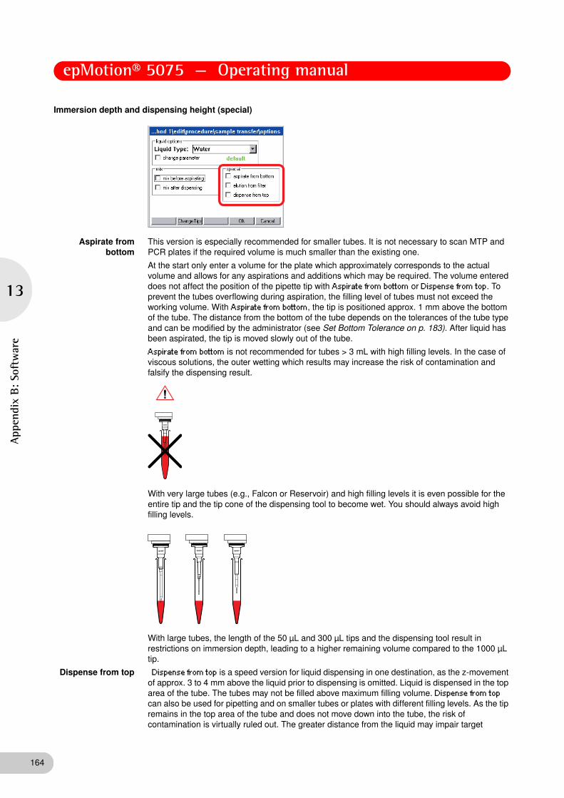
epMotion® 5075 — Operating manual
164
13
App
endi
x B: So
ftw
are
Immersion depth and dispensing height (special)
Aspirate from bottom
This version is especially recommended for smaller tubes. It is not necessary to scan MTP and PCR plates if the required volume is much smaller than the existing one.
At the start only enter a volume for the plate which approximately corresponds to the actual volume and allows for any aspirations and additions which may be required. The volume entered does not affect the position of the pipette tip with Aspirate from bottom or Dispense from top. To prevent the tubes overflowing during aspiration, the filling level of tubes must not exceed the working volume. With Aspirate from bottom, the tip is positioned approx. 1 mm above the bottom of the tube. The distance from the bottom of the tube depends on the tolerances of the tube type and can be modified by the administrator (see Set Bottom Tolerance on p. 183). After liquid has been aspirated, the tip is moved slowly out of the tube.
Aspirate from bottom is not recommended for tubes > 3 mL with high filling levels. In the case of viscous solutions, the outer wetting which results may increase the risk of contamination and falsify the dispensing result.
With very large tubes (e.g., Falcon or Reservoir) and high filling levels it is even possible for the entire tip and the tip cone of the dispensing tool to become wet. You should always avoid high filling levels.
With large tubes, the length of the 50 μL and 300 μL tips and the dispensing tool result in restrictions on immersion depth, leading to a higher remaining volume compared to the 1000 μL tip.
Dispense from top Dispense from top is a speed version for liquid dispensing in one destination, as the z-movement of approx. 3 to 4 mm above the liquid prior to dispensing is omitted. Liquid is dispensed in the top area of the tube. The tubes may not be filled above maximum filling volume. Dispense from top can also be used for pipetting and on smaller tubes or plates with different filling levels. As the tip remains in the top area of the tube and does not move down into the tube, the risk of contamination is virtually ruled out. The greater distance from the liquid may impair target

epMotion® 5075 — Operating manual
13
Appendix B
: Software
accuracy at minimal dispensing volumes. With a small volume and tubes > 5 mL, the tip might not reach the bottom of the tube or the liquid provided. There is a risk of the liquid touching the tube wall above the liquid provided. With larger volumes, liquid could well splash up. Certain dispensing speeds may not be exceeded for acceptable dispensing. Dispense from top should be validated by corresponding trials.
Elution from filter This function is especially suited to the aspiration of liquids from corresponding filter plates (currently only PCR cleanup filter plates). The following special features apply to this option:
• Do not enter a volume for Sample Transfer.
• The piston movement in the dispensing tool for aspirating liquid starts as soon as the tip starts moving down in the well. maximum stroke is used on every dispensing tool. This also applies to dispensing.
• The tip travels easily into the resilient filter material.
• In combination with the test PCR cleanup, a Mix before aspirating is recommended.
• The Elution from filter function refers to the source.
With the elution function, virtually complete aspiration of the liquid from the filter plate is achieved.
• In the Sample Transfer command under Transfer Type select pipette.
• The aspirated liquid is dispensed in the destination.
When transporting the liquid, the usual appearance of the liquid in the pipette tip does not apply. There may be air bubbles at several points in the pipette tip. The air segment at the bottom end of the pipette tip may not be clearly pronounced.
At different volumes you save time if the optical sensor is not used to determine liquid level. However, selecting Aspirate from bottom and Dispense from top ensures that liquids are dispensed and professionally dispensed. You are still asked at the start to enter a volume for a plate with 96 wells (exception: destination plates which had a volume "0" when the worktable was edited). The intention is to select an average volume for all wells with Aspirate from bottom or Dispense from top.
Changing pipette tips (Change Tips)
You can determine the time that tips are changed. To do so, press the Change Tips function key:
The following is displayed:
165

epMotion® 5075 — Operating manual
166
13
App
endi
x B: So
ftw
are
Change tips ...
• ... when command is finished
The tips are not ejected until the command is finished. This is recommended in the case of repeated aspiration of a particular reagent for filling all the wells of a plate, for example.
• ... before aspirating from next well, tube or position
Tip change before aspirating from a new position. If many different liquids are aspirated from a plate or rack, the new liquids must not come into contact with old remaining liquid in the tip. Tip change is therefore advisable.
• ... before each aspiration
No tip is filled twice, even if the same source for aspiration is involved. Should always be used with Mix after dispensing to prevent traces of liquid from a source being carried over as a result of mixing in a destination.
• ... keep tips, do not change tips
The tips continue to be used in the next command. If the next command is likewise defined with keep tips, do not change tips, use also continues to the command after next and so on (sensible if a nutrient medium is to be distributed on many empty plates, for example). Particularly with liquid which tends to foam, failing to change tips after multiple aspirations can lead to extra volume in the tip. This extra volume may cause contamination of the dispensing tool. If the pipette transfer type is changed to multidispense, after the first command an ejection occurs even if keep tips, do not change tips is selected.
Special features of multidispense:
• With multidispense, a slight extra volume needs to be aspirated.
• ... before aspirating from next well
– Extra volume is returned to the old source
– Change tip
– Aspirate liquid from new source
• ... before each aspiration:
– Extra volume is discarded into the waste
– Change tip
– Aspirate liquid from new or old source
13.1.3 Reagent Transfer
A reagent is transferred from one position of the source labware to several positions of the destination labware. Reagent Transfer is best suited to transferring a reagent to several plates. Abb. 1: Reagent Transfer principle
Fig. 1: Reagent Transfer principle
With Reagent Transfer, the Number of Samples entry relates to the destination.
All other entries and selection options are comparable to those of Sample Transfer.
Hint!
With Reagent Transfer, several source positions with liquid may be present.

epMotion® 5075 — Operating manual
13
Appendix B
: Software
13.1.3.2 Special case: use of several sources
For the reagent transfer, you can define methods in which more than one tube is to be defined as the source. The software can access the next tube automatically after the first tube has been emptied, to fill the destination plate for example. You no longer have to fill the first tube completely.
If the optical sensor is switched on, the first source tube is scanned. If, during this process, the software detects that there is too little liquid for the number of samples, the Checkrun window will appear. The minimum volume, maximum volume and calculated volume are displayed. You can now select how the optical sensor is to proceed (continue, abort, etc.).
To incorporate the next tube in the calculation, select accept level and continue. The optical sensor continues by scanning the next tubes. The volumes determined are totaled and the method started when the volume is adequate.
The optical scanner also scans empty tubes defined as source in the pattern. The message appears with a Calculated volume of 0 μL. Confirm with Accept level and continue to scan the subsequent tubes.
If level detection is switched off, a request to enter volume appears for the source locations of the pattern. The total volume required is assigned only to the first tube in the entry list. For all other source locations, "1" appears in the left-hand column. The "1" serves as a reminder to assign the individual volumes to the tubes.
167

epMotion® 5075 — Operating manual
168
13
App
endi
x B: So
ftw
are
13.1.4 Dilute
Dilute facilitates the creation of dilution series. A defined volume is transported from well to well by means of pipetting. Before the Dilute command, diluent (diluent reagent) must be dispensed using a Reagent Transfer command. The Reagent Transfer command fills the wells with the diluent required. Dilute can be executed using a source plate (undiluted samples) and a destination plate (dilution steps). Abb. 1: Dilute command principle (destination plate)
Fig. 1: Dilute command principle (destination plate)
The Number of Samples command ahead of Dilute specifies the number of samples to be diluted. The dilution steps are defined in the pattern and only possible within one location. They are limited by a row or a column.
If the Dilute command is executed within a single plate, source and destination areas may not overlap on the plate. This can be achieved by limiting the number of samples with the Number of Samples command.
13.1.4.2 Example dilution series
This example explains the principle of a dilution series. This is not a concrete application.
Sequence and objective of a dilution series
• 24 samples are in a rack with 24 tubes and are to be diluted 10:1.
• Dilution takes place in 3 stages with 1:10 dilutions in each case.
To achieve this, the 24 samples are transferred to a 96-well plate.
Diluent is transferred from a 300 mL reservoir to the 96-well plate.
Work is performed first with a single-channel dispensing tool and then later, to speed up the process, with an eight-channel dispensing tool.
Method
The worktable might look like this.
Undiluted Sample 1. Dilution 2. Dilution 3. Dilution
Diluent Diluent Diluent
Hint!
To achieve thorough mixing of sample and diluent, you should use Mix after dispensing. Mixing is performed after every dispensing step. Mix before aspirating refers only to mixing before the first aspiration, i.e. mixing the undiluted sample. All other entries and selection options are comparable to those of Sample Transfer.

epMotion® 5075 — Operating manual
13
Appendix B
: Software
First samples and then diluent should be transferred to the 96-well MTP. The dilutions are performed in the MTP 96. The method was edited under Procedure as follows to achieve this.
In the Sample Transfer command, 200 μL of sample are respectively put in the micro test plate.
The pattern for the 24 samples in the destination looks as follows:
In the Reagent Transfer command the empty wells of the micro test plate are filled with 225 μL of diluent. From this point on, an eight-channel dispensing tool executes the task.
The pattern of the destination looks like this:
In the sixth Dilute command, 25 μL of sample (A-1) is aspirated and mixed with the 225 μL of diluent (e.g., A-2). This is performed three consecutive times (A-3 and A-4). These three dilutions 1 + 9 (1:10) lead to a 1:1000 dilution (MTP columns 4, 8 and 12).
The call of show pattern in the Dilute command must show the following pattern for the source:
169

epMotion® 5075 — Operating manual
170
13
App
endi
x B: So
ftw
are
The pattern of the destination looks like this:
Each dilution step in this example is a 1:10 dilution. The desired dilution of 1:1000 is achieved by the third 1:10 dilution. The volume which is aspirated from the undiluted sample also applies to the dilution steps.
13.1.5 Pool
With the Pool command, you pool liquids from several wells, including from different source positions.
Because with multiaspirate following each sample aspiration a drawing-up of the liquid in the tip occurs, the aspirated liquid segments are in the beginning separated by air bubbles. When the tip is full, the contents are dispensed in the destination. You specify in the pattern from which positions of the source you pool for one position of the destination. Abb. 1: Pool command principle
Fig. 1: Pool command principle
13.1.5.2 Define pattern
The pattern for the Pool command differs slightly from the pattern for other transfer commands. The following steps briefly describe the special features of the Pool command.
1. In the parameter window of the Pool command click on the button next to Pattern.
2. In the Pattern window, click in the desired sequence on the source positions from which the liquid is to be pooled.
3. Click on the Destination function key and click in the destination plate on the position where the accumulated liquid is to be dispensed.
4. Switch to source and click on the next sequence of positions from which liquid is to be pooled.
5. In the Destination display, click on the next position at which pooled liquid is to be dispensed.
6. As soon as the pattern is identified, confirm with the Ok key.

epMotion® 5075 — Operating manual
13
Appendix B
: Software
13.1.5.3 Options
Change tips
Change tips ...
• ... when command is finished
Tips are changed when the command is finished.
• .... before aspiration for next destination well, tube
Is the default setting. Tips are only changed when the next pool has been assembled for the next destination position.
• .... after each dispense
Means that with the pipette dispensing variant, after dispensing in a new position, the tip is changed.
• … keep tips, do not change tips
Changing from pipette or multiaspirate to multidispense (or back again) is connected with an increased risk of contamination for the piston in the dispensing tool. Therefore, keep tips, do not change tips is disregarded with completion of the pool if the next command includes the multidispense dispensing variant. A tip change is therefore performed.
All other entries and selection options are comparable to those of Sample Transfer.
13.1.5.4 Enter Number of Samples for Pool
The number of samples entry relates to the source. The number of samples divided by "Number of Samples per Destination" gives the number of destination positions. If a decimal place results from the division, the number is rounded up for destination positions. The pattern in the source is likewise completed for the last destination position. In the Pool pattern, a maximum of the samples occurring in a row or column can be pooled.
Example: the samples of each column of a 96-well plate are to be pooled in a destination plate. In other words, 8 samples are always put into a tube.
• Number of Samples entry at start: 48
48 : 8 = 6
6 destination tubes are filled.
• Number of Samples entry at start: 50
50 : 8 = 6.25
7 destination tubes are filled.
The command is carried out in the source until inclusively the position 56 (requirement: no limitation in the Number of Samples command).
171

epMotion® 5075 — Operating manual
172
13
App
endi
x B: So
ftw
are
13.1.6 Pool One destination
Use the PoolOneDest command to dispense liquids from several source positions to one destination position.
The Number of Samples entry determines the number of positions in which aspiration will be performed. There is only one position as destination.
With the multiaspirate transfer type, the liquid is drawn up in the tip following every dispensing step. The same criteria apply here as to the Pool command.
13.1.6.1 Define pattern
The pattern for the Pool One Destination command differs slightly from the pattern for other transfer commands. The following steps briefly describe the special features for the Pool One Destination command. The positions in which there is to be aspiration and the direction for aspiration steps is specified in the pattern for the source. The destination is then only marked once.
1. In the parameter window of the command click on the button next to Pattern.
2. In the Pattern window, click on the first and second source position to specify the direction for pooling liquid.
3. Click on the Destination function key and click in the destination plate on the position where the accumulated liquid is to be dispensed.
4. As soon as the pattern is identified, confirm with the OK key.
13.1.6.2 Options
Change Tips
Change tips ...
• ... when command is finished
Is the default setting.
• ... after each dispense
Only meaningful with the pipette dispensing variant. With the multiaspirate dispensing variant and the selection of after each dispense tips are only changed after dispensing is finished. As with the Pool command, the combination multiaspirate and mix before aspirating with TestPara is rejected with an error message. Special case for
• … keep tips, do not change tips
Changing from pipette or multiaspirate to multidispense (or back again) is connected with an increased risk of contamination for the piston in the dispensing tool. This is why keep tips, do not change tips is not observed when finishing the command if the next command contains the multidispense dispensing variant. A tip change is therefore performed.
All other settings are comparable with Sample Transfer.

epMotion® 5075 — Operating manual
13
Appendix B
: Software
13.1.7 Mix
Use this command to mix liquids within a position.
The complete mixing process takes place in the liquid. When the liquid is aspirated and dispensed, the dispensing tool is moved on accordingly in the z direction. A mixing cycle consists of an upward and a downward movement. The travel results from the selected volume.
The descriptions of the mixing process for Sample Transfer (see Mix before aspirating or after dispensing (mix) on p. 163) also apply to this stand-alone Mix command.
13.1.7.1 Recommended mixing speeds (Speed)
Enter the mixing speed in the Speed window. The speed range is between 0.2 and 110 mm/sec.
As long as there is no entry in the input field for Speed, this field always displays the aspiration speed of the selected liquid type. The speeds in the Liquid Type parameters are optimized for pipetting or multidispensing in combination with the selected dispensing tool and the selected volume.
The optimum mixing speed should be determined in trials. Increase mixing speed carefully during these trials. Use very high speeds only for correspondingly viscous solutions.
Hint!
Use only 50 μL tips for mixing in 384-well plates!
Dispensing tool Recommended lower volume range
(mm/sec)
Recommended medium volume range
(mm/sec)
Recommended high volume range
(mm/sec)
TS 50 15 - 88 15 - 44 10 - 40
TM 50-8 15 - 88 15 - 44 10 - 40
TS 300 5 - 15 6 - 16 6 - 16
TM 300-8 2 - 11 2 - 11 2 - 11
TS 1000 4 - 15 4 -15 4 - 15
TM 1000-8 4 - 15 4 -15 4 - 15
Hint!
At very high speeds, large volumes and multiple mixing cycles, liquid may get into the dispensing tool (e.g. foam formation). In this case, perform method run tests using demineralized water. The use of filter tips will increase reliability.
173

epMotion® 5075 — Operating manual
174
13
App
endi
x B: So
ftw
are
13.1.7.2 Mixing volume
The mixing volume must always be less than the current filling volume in the tube, as the remaining volume of the aspiration cannot be used for mixing.
Mark the desired tube in the epMotion node and press Prop. to display the remaining volume. In the case of very large tubes (e.g., 15 mL) larger remaining volumes result with the 50 μL and 300 μL tips in combination with the geometry of the dispensing tool than with the 1000 μL tips.
13.1.7.3 Mixing functions at Fixed Height
With Fixed Height a mixing process with a defined aspirating height and dispensing height can be determined.
Enter the distance from the bottom of the tube in mm as the height.
Asp. stands for the distance of the pipette tip to the bottom of the tube when aspirating, Disp. stands for the distance of the pipette tip to the bottom of the tube when dispensing.
If you enter 0 mm in the Asp. field, a correction of approx. ca. 2 mm upwards occurs after the execution. The correction depends on tube type and the tolerances of the tube type.
If you choose for Disp. a height which lies above the tube the dispensing is reduced automatically to the height of the tube.
If you select a height for Disp., which is below that of Asp., Disp. is raised to a height of Asp. on execution.
13.1.7.4 Define pattern
The pattern for the Mix command differs slightly from the pattern for other commands. The following steps briefly describe the special features for the Mix command.
1. In the parameter window of the command click on the button next to Pattern.
2. In the Pattern window, click one by one on the rows of wells in which the Mix command is to be performed.
3. As soon as the pattern is identified, confirm with the OK key.
Hint!
Fixed Height should only be used for filling levels below the filling volume. At larger filling volumes, depending on the immersion depth selected, liquid may be forced out of the tube or well.

epMotion® 5075 — Operating manual
13
Appendix B
: Software
13.1.8 Transport
This command is used to transport labware from one position to another or to the Mastercycler (epMotion 5075 MC) or the vacuum unit (epMotion 5075 VAC) using the gripper.
In the parameter settings for the transport command, you select from lists the labware to be transported and the destination location.
The Vac Frame can be transported with a filter plate on it. Tips, racks, thermoadapters and height adapters cannot be transported. Semi-skirted and unskirted PCR plates can only be transported in the form of a thermoblock.
If the gripper is used, location B0 may only be occupied by a
• 300 mL or 400 mL reservoir,
• CycleLock or
• Height adapter
13.1.9 Temperature
The Temperature command is used to specify the temperature of a thermal module. The command can only be used on an epMotion equipped with thermal modules. If several thermal modules are available, you have to make the appropriate selection. For temperature control you can select a temperature between 0°C and 110°C. The current temperature of the thermal modules is shown in the display of the control panel directly above the function keys.
1. From the Location list select the thermal module for which you want to set the temperature.
2. Then mark Temperature on.
3. If the selected thermal module is to maintain the set temperature after the end of the method, mark keep temperature after method run. This command can also be used to preheat a thermal module for a subsequent method.
Temperature control is switched off after shutdown. For switch-off you can also define a separate method which does not include either temperature on or keep temperature after method run.
175

epMotion® 5075 — Operating manual
176
13
App
endi
x B: So
ftw
are
13.1.10 Thermomixer
This command can only be used on an epMotion with thermomixer. With the Thermomixer command you can specify the mixing parameters and the temperature of the thermomixer. For mixing you can set a maximum rotational speed of 2000 rpm and a temperature of 4°C to 95°C can be set for temperature control.
Select the Templates option to access a list of optimized templates for selected mixing tasks. You can change the templates as you wish and also use the Save Templ function key to create your own templates which will then also be available for selection in the list. Under the epMotion node in the TMX subnode you can delete or deselect your own templates in order to hide them in the list(see Enable/disable Labware or Labware combination on p. 144). Activate the Speed on function if you want to mix. Then you can enter the rotational speed (Speed) and the time (Time). You can enter a rotational speed between 300 - 2000 rpm and a time between 30 s and 120 min. Activate the Temperature on function if you want to temperature control the thermomixer. Then you can enter a temperature between 4°C and 95°C. If you want that the temperature is maintained during the method, activate the keep temperature after method run function.
This function can also be used for preheating the thermomixers for a subsequent method. If the thermal module is heated with keep temperature after method run beyond a method, you can switch it off by executing a thermomixer command with the Temperature On function disabled. Temperature control is switched off automatically after shutdown.
NOTICE!
Physical damage due to cross contamination and splashing liquid when using the Thermomixer command
With too high liquid level in the tubes and too high speeds liquids can splash out from the tubes which damage the device and can lead to cross contamination.
Do not mix at high rotational speed with high liquid levels.
Hint!
The lowest temperature reached by the thermomixer depends on the ambient temperature and can be a maximum of 15°C below room temperature. With a room temperature of e.g. 20°C, the lowest temperature reached by the thermomixer is 5°C

epMotion® 5075 — Operating manual
13
Appendix B
: Software
13.1.11 Vacuum
This command can only be executed on the epMotion VAC.
Use the Vacuum command to set the vacuum in the vacuum unit. To enable you to define the parameters for the Vacuum command in full, a Vac Frame and a Vac Lid must have been defined for the worktable.
You can adjust the required vacuum (8 maximum 50 mbar or 85 kPa) via Vac. pressure. You can select between the units of pressure mbar and kPa.
The Vacuum Time can be up to 99 minutes and 59 seconds.
To transport the Vac Lid at the beginning of the command by the gripper from the location T0 to the filter plate in the vacuum unit, activate Use vacuum lid . After the Vacuum time, at a residual vacuum of 100 mbar or 10 kPa, the Vac Lid is taken off again by the gripper and taken to location T0.
Check levels causes the scanning of all wells of a filter plate to detect any remaining volume. In this case, apply a vacuum again if required. With plates, Check levels can take a relatively long time.
13.1.12 Wait
Use the Wait command to insert a pause in the method, e.g., to take account of temperature control periods between two additions of reagent.
The duration of the pause is specified in the parameter settings.
The following applies only to epMotions with thermal modules:
If Wait for Temperature is selected, a selection list will appear from which the relevant thermal module (TEMP1 to TEMP3) can be selected. In addition, the following command is executed only once the specified temperature for the thermal module has been reached.
177

epMotion® 5075 — Operating manual
178
13
App
endi
x B: So
ftw
are
13.1.13 Comment
Use the Comment command to display a comment at a certain point during execution of the method.
The comment command entered is shown marked as a command line during the method run, no separate window is displayed.
The comment may be up to 15 characters long.
13.1.14 User intervention
Use this command to interrupt a method, for example to perform manual steps.
If there is to be an alarm immediately before the manual intervention, mark the Alarm field.
Enter a corresponding comment on the intervention in the Comment field.
For methods with external steps which lead to a change in volume, divide these into 2 methods.
The following things must not happen at all with User Intervention:
• Change in position of carrier.
• Exchange of dispensing tools in locations T1 – T4.
• Positioning of labware which is not known to the method.
• Labware which is removed and then replaced may not be changed externally in terms of volume.
• Distance from labware required in the method. The waste container can be emptied in conjunction with this command. Then position the waste container correctly again.
13.1.15 TempCycler
The command is only available on the epMotion 5075 MC with built-in Mastercycler ep.

epMotion® 5075 — Operating manual
13
Appendix B
: Software
With the TempCycler command the temperature of the cycler block and/or the cycler lid are controlled by a cycler program. To set temperature control, open the parameters of the TempCycler command. Reckon on a time of approx. 3 minutes to heat up the cycler block and the ESP heated lid.
13.1.16 StartCycler
Use the StartCycler command to select a cycler program and specify the start. This command must always be the last command of a method.
The desired cycler program is selected from a selection list in the parameter settings. Alternatively, the cycler program can be selected via the Open user tree button in the navigation tree.
If the cycler is operated without an epMotion, please note the following:
• If you work with simulated block control, after the start the number of samples and the filling volume are queried. You furthermore select between tube and plate.
• Cycler program without epMotion method: this is the only case in which you can use a semi-skirted or unskirted PCR plate.
To edit a cycler program,
1. Mark the cycler program and then press the Edit function key.
To exit the display, press the >> function key and then Exit.
Hint!
For detailed descriptions of cycler programs, refer to the operating manual for the Mastercycler.
179

epMotion® 5075 — Operating manual
180
13
App
endi
x B: So
ftw
are
13.2 Administrator rights
As administrator, you can perform additional activities on the epMotion 5075.
• Specify administrator PIN; recommended when you first start (see PIN Function on p. 180).
• Create, edit and delete user accounts (see Create and edit a user account on p. 181).
• Have unrestricted access to all user directories and edit or delete the methods stored in them.
• Deactivate labware which is not required from the full list of available labware (see Enable/disable Labware or Labware combination on p. 144).
• Compile your own labware combinations from existing components, e.g. rack/tube combinations (see Compile labware combination on p. 141).
• Perform different system functions (display available system memory, change date/time and country settings, activate or deactivate acoustic alarm and PINs).
13.2.1 PIN Function
If you are working with the PIN function, system settings and administration of user accounts is reserved for the administrator .
13.2.1.1 Initial start – set administrator PIN
At the initial start of the epMotion 5075, you can set an administrator PIN to protect the system from undesired access.
Perform the following steps in the sequence described.
1. Switch on the epMotion 5075 at the mains switch.
The control panel switches on automatically and the software is loaded.
After loading, the Input Admin PIN window appears in the display of the control panel.
Until you set an administrator PIN, this window appears every time you switch on .
2. Enter the desired administrator PIN using the numerical keys on the control panel. The PIN can be between 4 and 8 digits long.
Delete any incorrectly-entered PIN using the Delete key and repeat PIN entry.
3. For confirmation, enter the PIN in the Confirmation field once again.
Hint!
As a user, you can adjust display contrast and export logfiles.
NOTICE!
Loss of data due to misuse or loss of administrator PIN.
The administrator PIN protects the system from undesired access to its configuration and to the stored data of all users.
Make a note of the administrator PIN and keep it in a safe place. If you lose the administrator PIN, contact Eppendorf Service.
Allow access to the administrator PIN only to persons who are allowed to edit the configuration of the system and who have the knowledge required to do this.

epMotion® 5075 — Operating manual
13
Appendix B
: Software
4. Confirm with the OK function key.
The navigation tree appears in the display of the control panel.
You are now logged on as the Administrator and can edit the configuration settings of the epMotion 5075.
Detailed information about the navigation tree and operation of the control panel is given separately.
13.2.1.2 Change administrator PIN
As the administrator, you can change the administrator PIN at any time.
Perform the following steps in the sequence described.
1. Switch on the epMotion 5075 and log on as the Administrator.
2. Mark the System node in the navigation tree.
3. Press the Prop. function key.
The System Properties window appears.
4. Enter the new administrator PIN using the numerical keys on the control panel.
Delete any incorrectly-entered PIN using the Delete key and repeat PIN entry.
5. For confirmation, enter the PIN in the Confirmation field once again.
6. Confirm with the OK function key.
The new administrator PIN takes effect immediately.
13.2.1.3 Change user PIN
You can change the PIN for logging into your User Account at any time. To do this, proceed as follows.
1. In the navigation tree, mark your own User Directory.
2. Press the Prop. function key.
The User Properties window appears.
3. Enter the new user PIN using the numerical keys on the control panel. The PIN can be between 4 and 8 digits long.
Delete any incorrectly-entered PIN using the Delete key and repeat PIN entry.
4. For confirmation, enter the PIN in the Confirmation field once again
5. Confirm with the OK function key.
The new User PIN takes effect immediately.
13.2.2 User accounts
13.2.2.1 Create and edit a user account
If the epMotion 5075 is used by several people, you can set up an individual user account for each user.
Perform the following steps in the sequence described.
1. In the navigation tree, mark the top node - Eppendorf.
2. Press the NewUser function key.
The New User window appears in the display.
3. Enter a name and a PIN for the new user. Repeat the PIN in the Confirmation field to confirm it.
Hint!
User names can only be assigned once.
181

epMotion® 5075 — Operating manual
182
13
App
endi
x B: So
ftw
are
4. Confirm with the OK function key.
The new user account is set up. A new user directory for this user is created in the navigation tree.
The user can now log on with his or her PIN at any time.
5. To edit an existing user account, mark the user directory in the navigation tree and press the Prop. function key.
The User Properties window appears in the display. You can now alter the settings for the user account and confirm them with the OK function key.
13.2.2.2 Delete user account
Perform the following steps in the sequence described.
1. Mark the user directory in the navigation tree and press the Delete key.
A question appears in the display, asking whether you are sure you wish to delete the user.
2. Confirm with the OK function key.
The user account is deleted.
13.2.3 System settings
System settings are altered in the System node. Open the node to make the following settings.
Display Available System Memory • Mark System Memory and press the Show function key.
System memory is faded into the bottom of the display in the form of a red-and-green mark (red for used memory and green for free memory).
To remove the display, press the Show function key again.
Adjust Display Contrast 1. Mark LCD Contrast and press the Set function key.
2. Adjust contrast using the --- and +++ function keys and confirm by pressing Exit.
Change Date and Time 1. Mark Date + Time and press the Set function key.
2. Set date and time and confirm with OK.
Change Country Settings The country settings are classified by international telephone dialing prefix (e.g. 001 for the US).
In the country settings, you set the language and how date and time are displayed (12 or 24-hour format).
1. Mark Country Settings and press the Set function key.
2. Select the desired settings and confirm with OK.
The epMotion 5075 is shut down immediately. The modified settings apply after the next start.
Activate or Deactivate Acoustic Alarm • Mark the option Beeper and activate/deactivate.
If there is a red tick, the acoustic alarm is activated.

epMotion® 5075 — Operating manual
13
Appendix B
: Software
13.2.4 Set Bottom Tolerance
Bottom tolerance describes the distance between the calculated bottom of the tube and the calculated lowest part of the pipette tip. The default setting for bottom tolerance for the majority of tubes is 1 mm. For some reservoirs, it is 2.5 mm.
A reduction in bottom tolerance leads to a lower remaining volume and should only be used with expensive reagents. Reduced bottom tolerance should be examined again when changing batch of pipette tips, plates or tubes or if there is doubt about dispensing being correct.
In the case of special tasks, for example removing liquids from above a pellet, it is recommended that the factory-set bottom tolerance be increased. The user has sole responsibility for the correctness of dispensing and for straightforward aspiration in the case of tubes with altered bottom tolerance.
Change bottom tolerance
1. Mark the desired labware in the epMotion node and press the Edit function key.
2. Enter the bottom tolerance between 200 μm (0.2 mm) and 50 % of tube height. If required, change the specified name using the addition "cd" (change directory). Then press OK.
The main navigation is displayed and the changed labware is marked.
3. Press the Prop. function key.
The new values for the labware are displayed. The product information from the original labware file is not included.
A reduced bottom tolerance should be approved for use only following the appropriate test runs. With the 30 mL and 100 mL reservoirs in particular, the reservoir may not be lifted by the pipette tips during aspiration as a result of a reduction in bottom tolerance.
When calculating the Remaining Volume, the minimum immersion depth of 0.7 mm for the pipette tip in the liquid is included in addition to bottom tolerance. With the 30 mL and 100 mL reservoirs, volume information is not absolutely accurate in the case of reduced bottom tolerance (because of the serrated bottom).
Activate or Deactivate PINs The PIN option is used to specify whether work is carried out with or without entry of a PIN.
• Mark the option PIN and activate/deactivate.
The epMotion 5075 is shut down immediately. The modified settings apply after the next start.
183

epMotion® 5075 — Operating manual
184
13
App
endi
x B: So
ftw
are
13.2.4.1 Volume Check
To check the remaining volume of a tube, you should edit a method in which a small volume is aspirated from this tube step by step. Observe from which aspiration step too small a volume is aspirated into the pipette tip. The volume remaining in the tube and the last (defectively) aspirated volume combined give the approximate remaining volume. If remaining volume is considered too high, bottom tolerance can be reduced a little in the tube file. Bottom tolerance may not be selected to be so small that a pipette tip contacts the bottom.
Perform the test run as follows.
1. Select a Sample Transfer with 10 replicates for dispensing, for example, so as to be able to aspirate 10 times from the same tube/well.
2. Select pipette as the liquid transfer method and deactivate the Optical Sensor for level detection.
3. Under Options, select the aspirate from bottom parameter to ensure that the tip is always immersed to the bottom of the tube. With aspirate from bottom, the selected bottom tolerance of the tube or well always applies.
4. Select a liquid similar to that being used in practice so as to imitate effects like typical curvature of the surface of this type of liquid.
5. Start the method.
13.3 Manage and Backup Data
13.3.1 Backup Data
When you perform a backup of the data on the control panel, the program version and all labware specifications from the epMotion node, including liquid types and applications from the ep node in the epMotion 5075 memory, are copied to the MMC™.
Proceed as follows.
1. Ensure that there is an MMC™ in the slot on the right of the control panel.
2. Mark the Card node in the navigation tree.
3. Press the Backup function key.
A question appears, asking whether you want to perform a data backup.
4. Press the Yes function key.
The methods and labware specifications are written to the MMC™.
13.3.2 MultiMediaCard MMC™ Data Transfer
The function keys in the above display show the administrator's data transfer options. Users can only perform a backup here.
Insert the external MMC™ on the right-hand side of the control panel and mark the Card node.
Hint!
In the case of less stable plates it should be noted that the plate could be slightly bent. It is therefore not meaningful to reduce bottom tolerance with such plates.

epMotion® 5075 — Operating manual
13
Appendix B
: Software
Labware Labware controls the update of files (e.g. for new tubes or methods).
Backup Backup includes backing up the program version, the labware in the epMotion node including liquid types and applications in the ep node, to an external MMC™. With a backup, the external MMC™ is formatted. The data backed up externally using the Backup function can be restored to the internal MMC™ using the Restore command.
Restore Use Restore to transfer the version of the program stored on the external MMC™ and the associated data to the epMotion and the control panel. After that, only the data transferred using the Restore command are available in the control panel.
Firmware
The device software update is launched using the Firmware function key. After pressing the Firmware function key, a display appears. In this display, select whether you would like to carry out an update for the control panel or epMotion software. The control panel update must always be performed first.
Shut down the epMotion. To do so, press the Shutdown function key.
A current backup should always be performed immediately after an update of labware or firmware
Export
The Export function can be reached by marking a method. This function is used to export the method parameters using a PC and "epMotion Editor".
Proceed as follows to perform an export.
1. Plug the MMC™ into the slot on the right of the control panel.
2. Open the System node in the navigation tree.
3. Mark Logfile and press the Export function key.
The logfile is copied to the MMC™.
Do not use MMCs™ used for export for Restore or other data transfer operations to the internal MMC™ of the control panel.
185

epMotion® 5075 — Operating manual
186
13
App
endi
x B: So
ftw
are
13.4 Predefined methods
The node ep contains several applications in four subfolders for you to copy into your user directory from where you can edit or start them.
Mehods contained in ep cannot be started or edited there directly.
This section provides you with an overview of the available applications and a short description.
More detailed information on the applications in the list below and for additional applications can be found under "Applications" at www.epmotion.com.
13.4.1 Nucleic acid prep
13.4.2 PCR setup
13.4.3 Routine
Hint!
To better understand the descriptions you should display the contents of a method. Select the method and then click on the function key Show.
QIA RNeasy 96 RNA isolation with the help of a Qiagen kit.
QIAamp 96 DNA Blood DNA isolation in blood samples with the help of a Qiagen kit.
Promega_mag_96 Method for the automated DNA extraction with the "Promega Wizard Magnetic 96 DNA Plant System".
Modular rack A Method for filling a PCR plate with 8 different DNA samples and 12 different primer pairs from a full reservoir rack.
10 ml tubes to plate Uses a 16 mm rack with 10 mL tubes (tubes with conical bottom and screw cap) to fill four rows of a 96er twin.tec PCR plate in turn.
384 to 4x96 Sample transfer of a 384 well plate to four 96 well plates. Design with eight channel dispensing tool.
4x24 to 96 Sample transfer of four thermoracks to a 96 well PCR plate.
4x96 to 384 Sample transfer of four 96well plates to one 384 well plate.
96 to 4x24 Sample transfer of a 96 well plate to four thermoracks. Design with single channel dispensing tool.
Admirable results Filling of two Deepwell plates 2.2 mL with 1000 μL per well. Sampling from four 100 mL reservoirs.
Dilute 1to10 – 1to1000 Executing a diluting series using the Dilute command. By way of reagent transfer diluent is transfered to a 96 well plate. By way of sample transfer samples are then transfered from a 24 well rack into the still empty columns of the plate in front of the already dispensed diluent.
The transfered undiluted sample is then diluted in three stages (Dilute command).

epMotion® 5075 — Operating manual
13
Appendix B
: Software
13.4.4 Sequencing setup
Disperse from 1 to 2 Using Sample Transfer a transfer is made from a 96 well plate to two 96 well PCR plates.
An eight channel dispensing tool is used. Each sample is dispensed with the same tip to two different plates.
The tip is changed prior to sampling a new sample.
Fill 24 Simple fast method for filling a 24 well thermorack with 1000 μL liquid pro Safe Lock tube. Sampling from a 30 mL reservoir.
Fill 384 Simple fast filling of a 384 well twin.tec PCR plate with 20 μL water per well using the dispensing tool TM 50-8.
Dispensing is carried out as multi-dispensing. Sampling from a 30 mL reservoir. The method is recommended for checking the dispensing precision.
It is highly recommended to also dispense and evaluate using the dispensing version "pipette".
Fill 96 Simple fast filling of a 96 well twin.tec PCR plate with 100 μL water per well using the dispensing tool TM 300-8.
Dispensing is carried out as multi-dispensing. Sampling from a 30 mL reservoir. The method is recommended for checking the dispensing precision.
It is highly recommended to also dispense and evaluate using the dispensing version "pipette".
LI384_1 Method fills a 384 well plate with different solutions in a "checkered" pattern using a single channel dispensing tool.
The method and in particular the pattern shown can thus be used as the basis for independent contamination checks
Modification of volume, plate, liquid type etc. is recommended for the actual task.
LI384_8 Similar to LI384_1 but using an eight channel dispensing tool.
The checkered pattern results from the fact that the eight channel dispensing tool can only fill every second well of a 384 well plate. The method and in particular the pattern shown can thus also be used as the basis for independent contamination checks
Modification of volume, plate, liquid type etc. is recommended for the actual task.
Modular rack B Filling of two 24 well platds with 1,800 μL liquid A and 2,000 2.000 μL liquid B from a reservoir rack equipped with modular rackes with 50 mL and 15 mL tubes.
Pattern1 Filling every second column of a 96 well plate using the dispensing tool TM 300-8. Filling the columns using a reagent transfer.
Reagent sampling from a 30 mL reservoir.
Pool Using the Pool command 4 adjacent wells in a column of a 96 well plate are combined ("aspirate") and transfered into a Safe Lock tube in a thermorack.
PoolOneDestination Collecting the content of a 96 well plate in a 300 mL reservoir.
Stack Example for stacking plates in a method with greater throughput.
ABI 384 For preparation of the mastermixe see method properties. The method can be executed with every epMotion
The method dispenses mastermix and templates in a 384well twin.tec PCR plate.
ABI 96 For preparation of the mastermixe see method properties. The method can be executed with every epMotion
The method dispenses mastermix and templates in a 96well twin.tec PCR plate.
Amersham 384 The method dispenses mastermix and template to max. 384 locations of a twin.tec PCR plate.
Amersham 96 The method dispenses mastermix and template to max. 96 locati ons of a twin.tec PCR plate.
187

epMotion® 5075 — Operating manual
188
Inde
x
Index
Index
AAccessories
Item number .............................................................116
Accessories for nucleic acid purificationItem number .............................................................117
AdaptersLabware folder/.........................................................140Thermoadapter Frosty..............................................136
Add ..................................................................................52
Administrator Function ...................................................180
Administrator PINChange.....................................................................181Set............................................................................180
AlarmActivate.....................................................................182Deactivate ................................................................182
All positions......................................................................46
Application Support........................................................145
Aspirate from bottom......................................................164
Aspiration volume ............................................................26
Autoclaving CycleLock................................................................111 Dispensing Tools.....................................................110 Vac Lid ....................................................................111 Vacuum unit ............................................................110Gripper .....................................................................110Thermoadapter, thermoblock, thermorack ...............111
Automated pipetting systemItem number .............................................................116
BBackup...........................................................................185
Beeper ...........................................................................182
before aspirating from next well, tube or position...........166
before each aspiration ...................................................166
Bottom Tolerance...........................................................183
CCard .................................................................................37
CarrierTechnical data ..........................................................115
Change Country Settings...............................................182
Change Date..................................................................182
Change liquid type .........................................................159
Change parameter .........................................................161
Change Time .................................................................182
Change tips....................................................................165
Channeling plate............................................................131
Check levels...................................................................177
Cleaning
Control panel ........................................................... 110Dispensing Tools...................................................... 109Gripper..................................................................... 110Thermoadapter, thermoblock, thermorack ............... 110Thermomixer............................................................ 110Vac Lid ..................................................................... 110Vacuum unit ............................................................. 110Worktable base adapter........................................... 109Worktable................................................................. 109
column-wise..................................................................... 58
CommandAdd to procedure ....................................................... 52Edit parameters.......................................................... 53Remove from procedure ............................................ 53Specify destination..................................................... 54Specify pattern ........................................................... 55Specify source ........................................................... 54
CommandsComment ................................................................. 178Dilute........................................................................ 168Mix ........................................................................... 173Number of Samples ................................................. 151Overview.................................................................... 48Pool.......................................................................... 170Pool One destination................................................ 172Reagent Transfer ..................................................... 166Sample Transfer....................................................... 153StartCycler ............................................................... 179TempCycler .............................................................. 178Temperature............................................................. 175Thermomixer............................................................ 176Transport.................................................................. 175User intervention...................................................... 178Vacuum.................................................................... 177Wait.......................................................................... 177
Comment ................................................................. 51, 178
Confirmation .................................................................. 181
ContrastAdjust ....................................................................... 182
Control PanelTasks.......................................................................... 20
Country Settings............................................................ 182
CycleLock Autoclaving ............................................................. 111
Cycler programCreate ........................................................................ 44
DData
Backup..................................................................... 184
Date + Time................................................................... 182
Decontamination............................................................ 111
Define module rack........................................................ 131Define ...................................................................... 143Item number............................................................. 119
Delete .............................................................................. 40

epMotion® 5075 — Operating manual
Index
DestinationButton.........................................................................53Define.........................................................................54
Detection versions .........................................................148
Dilute........................................................................50, 168
Dimensions ....................................................................112
Dispense from top..........................................................164
Dispensing error ..............................................................77
Dispensing toolSealing ring replacement .........................................108
Dispensing Tools......................................................16, 145Autoclaving...............................................................110Cleaning ...................................................................109Item number .............................................................116Technical data ..........................................................113
Display Contrast.............................................................182
Display System Memory ................................................182
Disposal .........................................................................122
DWP...................................................................................8
EElution from filter ............................................................165
ENTER.............................................................................38
EP ....................................................................................37
epMotionSoftware node ............................................................37
EppendorfSoftware node ............................................................37
epT.I.P.S. Motion............................................................124Item number .............................................................117
Equip Holder with Tubs + ModulesLabware folder/.........................................................140
Error messagesDispensing error.........................................................77Optical sensor read error ...........................................76
Export ....................................................................185, 185
FFault finding .....................................................................76
Filling volume...................................................................24
Firmware ........................................................................185
Fixed ..............................................................................151
Fluid displacement...........................................................24
FolderCreate ........................................................................43
GGripper
Autoclaving...............................................................110Cleaning ...................................................................110Item number .............................................................116Labware .....................................................................41Labware folder/.........................................................141
Tasks.......................................................................... 17Technical data.......................................................... 115
HHeight Adapter............................................................... 135
Item number............................................................. 119
IInput Admin PIN ............................................................ 180
Insert ............................................................................... 53
Installationeach lot ...................................................................... 34
Intended UseWarnings.................................................................... 29
Kkeep tips, do not change tips......................................... 166
Keys........................................................................... 38, 40Cursor ........................................................................ 39Delete......................................................................... 40ENTER....................................................................... 38Function keys ............................................................. 39Start ........................................................................... 39Stop............................................................................ 39
LLabware
Compile a combination ............................................ 141definition .................................................................. 145Folder....................................................................... 141Labware ..................................................................... 41
LCD Contrast ................................................................. 182
LidsLabware folder/ ........................................................ 140
Liquid Detection................................................. 20, 60, 149
Liquid options ................................................................ 159
Liquid typesParameter ................................................................ 161
Liquids ........................................................................... 141
Logfile ............................................................................ 185Export ...................................................................... 185
Login.......................................................................... 34, 34
MMaintenance
Dispensing tool sealing ring ..................................... 108Dispensing Tools...................................................... 109
Maximum no. of Samples .............................................. 151
Menu structure................................................................. 36
MethodAbort .......................................................................... 65Check......................................................................... 59Check Labware prior to start...................................... 76Continue .................................................................... 65Copy........................................................................... 60
189

epMotion® 5075 — Operating manual
190
Inde
x
Create ........................................................................44Create folder ..............................................................43Define.........................................................................44Edit .............................................................................45Predefined..................................................................60Protect ........................................................................44Start .....................................................................43, 61Stop............................................................................63Test runs before start .................................................62Write protection ..........................................................44
MethodsNucleic acid prep......................................................186PCR setup................................................................186Predefined................................................................186Routine.....................................................................186Sequencing setup ....................................................187
Mix ...........................................................................51, 173Fixed Height .............................................................174Mixing volume ..........................................................174SPEED.....................................................................173
mix after dispensing.......................................................163
mix before aspirating......................................................163
Mixing ............................................................................163
Mixing speed..................................................................173
Mixing volume................................................................174
Mode of operation............................................................13
MTP ...................................................................................8
MultiMediaCard (MMC™) ................................................21
NNavigation tree.................................................................37
New Cmd .........................................................................52
New Method.....................................................................44
New pat............................................................................59
New User .......................................................................181
Next..................................................................................38
Noise level .....................................................................114
Nucleic acid prepMethods ...................................................................186
Number of Samples .................................................48, 151
Numerical keys ................................................................40
OOpen user tree...............................................................179
Operating controlsControl panel..............................................................20Dispensing Tools........................................................16Gripper .......................................................................17MultiMediaCard (MMC™) ..........................................21Optical sensor ............................................................20Overview ....................................................................14Worktable ...................................................................14
Operating Sequence........................................................40
Operation
Control panel ............................................................. 36
Optical sensorActivate ...................................................................... 60All positions................................................................ 46Check labware ........................................................... 60Check tip rack ............................................................ 60Deactivate .................................................................. 60Detection limits......................................................... 150Detection versions ................................................... 148Function ................................................................... 147Liquid Detection ................................................... 46, 60Random Access......................................................... 46Read error.................................................................. 76Tasks.......................................................................... 20Technical data.......................................................... 114Tip detection ............................................................ 149
OptionsButton......................................................................... 54
PParameter
Edit............................................................................. 53Filter Tips ................................................................. 153Fixed ........................................................................ 151Maximum no. of Samples ........................................ 151multidispense........................................................... 153Pipet.Tool ................................................................. 153Pipette...................................................................... 153Test ............................................................................ 59Transfer Type ........................................................... 153Volume..................................................................... 153
PatternCheck......................................................................... 59Define ........................................................................ 55Standard .................................................................... 58
PCR................................................................................... 8
PCR accessoriesItem number............................................................. 120
PCR setupMethods ................................................................... 186
PINActivate .................................................................... 183Administrator............................................................ 180Change .................................................................... 181Change User PIN..................................................... 181Deactivate ................................................................ 183Set............................................................................ 180
Pipet.Tool....................................................................... 153
Pipette tips..................................................................... 124Change .................................................................... 165Item number............................................................. 117
PlaceLabware ..................................................................... 45
Plates............................................................................. 136Labware files............................................................ 136Labware folder/ ........................................................ 140

epMotion® 5075 — Operating manual
Index
Pool..........................................................................50, 170
Pool One destination................................................50, 172
Press..............................................................44, 48, 61, 65
Press theEdit .............................................................................48Info .............................................................................61Location......................................................................45Parameter...................................................................53Procedure...................................................................48
Press the New Folder.................................................................43
ProcedureAdd command ............................................................52Define.........................................................................48Remove command .....................................................53
Procedure mode ..............................................................48
RRack 96..........................................................................126
Rack LC .........................................................................126
Racks.............................................................................125Item number .............................................................118
Random Access.......................................................46, 149
Reagent reservoirsItem number .............................................................118
Reagent Transfer .....................................................49, 166
Reagent tubes ...............................................................125
Remaining volume ...........................................................25Special cases .............................................................25
RemoveLabware .....................................................................46
Reservoir rack................................................................130
Reservoirs......................................................................130Item number .............................................................118
Restore ..........................................................................185
Reverse stroke.................................................................26
RoutineMethods ...................................................................186
Row-wise .........................................................................58
SSafety Instructions
Meaning of Symbols.....................................................7
Safety devices..................................................................32
Sample Transfer.......................................................48, 153
Sequencing setupMethods ...................................................................187
Set Bottom Tolerance ....................................................183
Show pat. .........................................................................59
Shut Down .......................................................................65
Shutdown.........................................................................65
Software
Menu structure ........................................................... 36Navigation .................................................................. 37
Software versionControl panel ............................................................. 37epMotion .................................................................... 37
SourceButton......................................................................... 53Define ........................................................................ 54
StackLabware ............................................................... 47, 47
StandardPattern ....................................................................... 58
Start ................................................................................. 39
StartCycler..................................................................... 179
Stop ................................................................................. 39
Support.......................................................................... 145
Switch Off ........................................................................ 65
Switch-on......................................................................... 34
SystemSoftware node............................................................ 37
System Memory............................................................. 182
System Properties ......................................................... 181
System settings ............................................................. 182
TTechnical Data
Dimensions .............................................................. 112Weight...................................................................... 112
TempCycler.................................................................... 178
TemperatureCommand ................................................................ 175
Test runs.......................................................................... 62
TestPara .......................................................................... 59
Text input ......................................................................... 40
Thermal moduleItem number............................................................. 117Technical data.......................................................... 115Temperature settings ............................................... 150
Thermoadapter .............................................................. 129Autoclaving .............................................................. 111Cleaning................................................................... 110
Thermoadapter Frosty ................................................... 136
Thermoadapter LC Sample ........................................... 129
ThermoblockAutoclaving .............................................................. 111Cleaning................................................................... 110Cooling effect ........................................................... 129
Thermoblocks ........................................................ 127, 128
Thermoblocks with plates .............................................. 141
Thermomixer ............................................................. 18, 50Cleaning................................................................... 110Command ................................................................ 176
191

epMotion® 5075 — Operating manual
192
Inde
x
Maximum speed.........................................................64Technical data ..........................................................115
ThermorackAutoclaving...............................................................111Cleaning ...................................................................110Cooling effect ...........................................................129
Thermorack and 0.2 mL tubes.......................................128
Thermoracks..........................................................127, 128
Tip detection ..................................................................149
Tips ................................................................................124Labware folder/.........................................................140
Tools ..............................................................................145Labware folder/.........................................................141
Transport..........................................................................50Command.................................................................175
Tubes + (Thermo)racks + ModulesLabware folder/.........................................................140
TubsLabware folder/.........................................................141
Two Location Rack.........................................................126
UUpdate ...........................................................................185
Use vacuum lid ..............................................................177
User AccountCreate ......................................................................181Delete.......................................................................182Edit ...........................................................................181
User directoryCreate folder ..............................................................43
User Intervention .............................................................51
User Login .......................................................................34
User Properties......................................................181, 182
VVac Lid
Autoclaving..............................................................111Cleaning ...................................................................110
VacuumCommand.................................................................177
Vacuum FramesLabware folder/.........................................................140
Vacuum time ..................................................................177
Vacuum unit ...............................................................19, 42 Autoclaving..............................................................110Cleaning ...................................................................110Technical data ..........................................................115
Volume.............................................................................26Aspiration volume.......................................................26CORRECTION...........................................................28Extra aspiration ..........................................................26Filling volume .............................................................24Remaining volume .....................................................25
Required volume........................................................ 27Reverse stroke ........................................................... 26terms.......................................................................... 24Working volume ......................................................... 24
Volume check .................................................................. 27
WWait ......................................................................... 51, 177
Weight ........................................................................... 112
when command is finished ............................................ 166
Worktable base adapterCleaning................................................................... 109
Working volume............................................................... 24
WorktableButton......................................................................... 45Cleaning................................................................... 109Locations ................................................................... 14Placing the gripper ..................................................... 41Position labware......................................................... 41Position labware via software..................................... 45Remove labware via software .................................... 46
Worktable mode .............................................................. 45


Eppendorf offices
Eppendorf offices
AUSTRALIA & NEW ZEALAND
Eppendorf South Pacific Pty. Ltd.Phone: +61 2 9889 5000Fax: +61 2 9889 5111E-mail: [email protected]: www.eppendorf.com.au
AUSTRIA
Eppendorf Austria GmbHPhone: +43 (0) 1 890 13 64 - 0Fax: +43 (0) 1 890 13 64 - 20E-mail: [email protected]: www.eppendorf.at
BRAZIL
Eppendorf do Brasil Ltda.Phone: +55 11 30 95 93 44Fax: +55 11 30 95 93 40E-mail: [email protected]: www.eppendorf.com.br
CANADA
Eppendorf Canada Ltd.Phone: +1 905 826 5525Fax: +1 905 826 5424E-mail: [email protected]: www.eppendorfna.com
CHINA
Eppendorf China Ltd.Phone: +86 21 38560500Fax: +86 21 38560555E-mail: [email protected]: www.eppendorf.cn
CZECH REPUBLIC
Eppendorf Czech & Slovakia s.r.o.Phone: +420 323 605 454Fax: +420 323 605 454E-mail: [email protected]: www.eppendorf.cz
FRANCE
Eppendorf France S.A.R.L.Phone: +33 1 30 15 67 40Fax: +33 1 30 15 67 45E-mail: [email protected]: www.eppendorf.fr
GERMANY
Eppendorf Vertrieb Deutschland GmbHPhone: +49 2232 418-0Fax: +49 2232 418-155E-mail: [email protected]: www.eppendorf.de
INDIA
Eppendorf India LimitedPhone: +91 44 42 11 13 14Fax: +91 44 42 18 74 05E-mail: [email protected]: www.eppendorf.co.in
ITALY
Eppendorf s.r.l.Phone: +390 2 55 404 1Fax: +390 2 58 013 438E-mail: [email protected]: www.eppendorf.it
JAPAN
Eppendorf Co. Ltd.Phone: +81 3 5825 2363Fax: +81 3 5825 2365E-mail: [email protected]: www.eppendorf.jp
NORDIC
Eppendorf Nordic ApsPhone: +45 70 22 2970Fax: +45 45 76 7370E-mail: [email protected]: www.eppendorf.dk
SLOVAKIA
Eppendorf Czech & Slovakia s.r.o.Phone: +421 911 181 474E-mail: [email protected]: www.eppendorf.sk
S
EpPhFaE-epInt
OUTH & SOUTHEAST ASIA
pendorf Asia Pacific Sdn. Bhd.one: +60 3 8023 2769x: +60 3 8023 3720mail: [email protected]: www.eppendorf.com.my
SPAIN
Eppendorf Ibérica S.L.U.Phone: +34 91 651 76 94Fax: +34 91 651 81 44E-mail: [email protected]: www.eppendorf.es
SWITZERLAND
Vaudaux-Eppendorf AGPhone: +41 61 482 1414Fax: +41 61 482 1419E-mail: [email protected]: www.eppendorf.ch
THAILAND
Eppendorf (Thailand) Co. Ltd.Phone: +66 2 379 4212-5Fax: +66 2 379 4216E-mail: [email protected]: www.eppendorf.com.my
UNITED KINGDOM
Eppendorf UK LimitedPhone: +44 1223 200 440Fax: +44 1223 200 441E-mail: [email protected]: www.eppendorf.co.uk
USA
Eppendorf North America, Inc.Phone: +1 516 334 7500Fax: +1 516 334 7506E-mail: [email protected]: www.eppendorfna.com
O
Intewo
THER COUNTRIES
rnet: www.eppendorf.com/rldwide

In touch with life
Your local distributor: www.eppendorf.com/worldwide · Eppendorf AG Hamburg · Germany · E-mail: [email protected] Support Europe: Tel: +49 1803 666 789 (Preis je nach Tarif im Ausland; 9 ct/min aus dem dt. Festnetz; Mobilfunkhöchstpreis 42 ct/min)
[email protected] America: Tel: +1 516 334 7500 · Toll free phone: +1 800 645 3050 · E-mail: [email protected]
Asia Pacific: Tel: +60 3 8023 6869 · E-mail: [email protected]