epn 4.0 system concept guide 1-1 evolved programmable network (epn) 4.0 system concept guide 1...
TRANSCRIPT
Evolved Programmable Networks (EPN) 4.0 System Concept GuideOctober 2014
Building Architectures to Solve Business Problems

CVD Document Titleii
About Cisco Validated Design (CVD) Program
The CVD program consists of systems and solutions designed, tested, and documented to facilitate faster,
more reliable, and more predictable customer deployments. For more information visit http://
www.cisco.com/go/designzone.
ALL DESIGNS, SPECIFICATIONS, STATEMENTS, INFORMATION, AND RECOMMENDATIONS (COLLECTIVELY,
"DESIGNS") IN THIS MANUAL ARE PRESENTED "AS IS," WITH ALL FAULTS. CISCO AND ITS SUPPLIERS DISCLAIM ALL
WARRANTIES, INCLUDING, WITHOUT LIMITATION, THE WARRANTY OF MERCHANTABILITY, FITNESS FOR A PARTIC-
ULAR PURPOSE AND NONINFRINGEMENT OR ARISING FROM A COURSE OF DEALING, USAGE, OR TRADE PRAC-
TICE. IN NO EVENT SHALL CISCO OR ITS SUPPLIERS BE LIABLE FOR ANY INDIRECT, SPECIAL, CONSEQUENTIAL,
OR INCIDENTAL DAMAGES, INCLUDING, WITHOUT LIMITATION, LOST PROFITS OR LOSS OR DAMAGE TO DATA
ARISING OUT OF THE USE OR INABILITY TO USE THE DESIGNS, EVEN IF CISCO OR ITS SUPPLIERS HAVE BEEN
ADVISED OF THE POSSIBILITY OF SUCH DAMAGES.
THE DESIGNS ARE SUBJECT TO CHANGE WITHOUT NOTICE. USERS ARE SOLELY RESPONSIBLE FOR THEIR
APPLICATION OF THE DESIGNS. THE DESIGNS DO NOT CONSTITUTE THE TECHNICAL OR OTHER PROFESSIONAL
ADVICE OF CISCO, ITS SUPPLIERS OR PARTNERS. USERS SHOULD CONSULT THEIR OWN TECHNICAL ADVISORS
BEFORE IMPLEMENTING THE DESIGNS. RESULTS MAY VARY DEPENDING ON FACTORS NOT TESTED BY CISCO.
The Cisco implementation of TCP header compression is an adaptation of a program developed by the University of
California, Berkeley (UCB) as part of UCB’s public domain version of the UNIX operating system. All rights reserved.
Copyright © 1981, Regents of the University of California.
Cisco and the Cisco logo are trademarks or registered trademarks of Cisco and/or its affiliates in the U.S. and other
countries. To view a list of Cisco trademarks, go to this URL: http://www.cisco.com/go/trademarks. Third-party trade-
marks mentioned are the property of their respective owners. The use of the word partner does not imply a partner-
ship relationship between Cisco and any other company. (1110R).
Any Internet Protocol (IP) addresses and phone numbers used in this document are not intended to be actual
addresses and phone numbers. Any examples, command display output, network topology diagrams, and other fig-
ures included in the document are shown for illustrative purposes only. Any use of actual IP addresses or phone num-
bers in illustrative content is unintentional and coincidental.
Evolved Programmable Networks (EPN) 4.0 System Concept Guide
© 2014 Cisco Systems, Inc. All rights reserved.
System Concept Guide
C O N T E N T S
C H A P T E R 1 Solution Overview 1-1
Optimized Costs 1-1
Improved Customer Retention 1-2
Increased and Facilitated Monetization 1-2
System Evolution 1-3
C H A P T E R 2 System Architecture 2-1
Transport Infrastructure 2-4
Unified MPLS 2-5
Transport Network Models 2-6
Transport Control Plane 2-11
Route Scale Control 2-12
Multicast 2-14
Integration with Microwave ACM 2-15
Autonomic Networking (AN) 2-16
Service Infrastructure 2-17
Consumer Services 2-19
Consumer Wireline Access 2-20
Consumer Wi-Fi Access 2-22
Consumer Mobile Access 2-23
Enterprise Service Models 2-23
Transport Services—MEF 2-26
E-LAN and E-Tree Services 2-27
E-Line Services 2-28
MEF Services with Zero Touch Deployment Ethernet NIDs 2-29
Transport Services—Mobile Service Models 2-30
Mobile Transport Capacity Monitoring 2-33
Service Control Plane 2-34
Subscriber Experience Convergence 2-35
Unified Subscriber Experience 2-36
Personalized Enterprise L3VPNs with Fixed And Mobile Access 2-37
Seamless Remote Access to Enterprise L3VPN 2-38
1Evolved Programmable Network (EPN) 4.0

Contents
C H A P T E R 3 Functional Components 3-1
Quality of Service (QoS) 3-1
Redundancy and High Availability 3-3
Transport Infrastructure Layer Resiliency Mechanisms 3-4
Service Infrastructure Layer Resiliency Mechanisms 3-5
OAM and Performance Monitoring 3-6
Subscribers Identity Management 3-7
Synchronization Distribution 3-8
C H A P T E R 4 Conclusion 4-1
A P P E N D I X A Related Documents A-1
2Evolved Programmable Network (EPN) 4.0
System Concept Guide

System Concept Guide
C H A P T E R 1
Solution OverviewInfused with intelligence and select solutions for scalability, agile transport, and security, the Cisco® Evolved Programmable Network (EPN) System builds towards a flexible and programmable network infrastructure, targeted to deliver service providers (SPs) with cost optimization, improved customer retention, and increased monetization.
Through the fusion of network and cloud over programmable interfaces, the EPN System builds a platform for SP innovation and differentiation. Designed to concurrently support consumer and enterprise services over a single converged network infrastructure, the system successfully complements traditional service offerings with the integration and virtualization of networking functions, optimal placement of the service edge, and selection of different access options. It also offers a unified and personalized network access experience to subscribers, which is applicable to any type of access and even extends to Bring Your Own Device (BYOD) users.
The chapter, which describes in detail the benefits the EPN System delivers to operators, includes the following major topics:
• Optimized Costs, page 1-1
• Improved Customer Retention, page 1-2
• Increased and Facilitated Monetization, page 1-2
• System Evolution, page 1-3
Optimized CostsWith the pace of change constantly accelerating, SP offerings have dramatically changed over the past two decades. Simple point-to-point transport services offered to enterprises have morphed into dozens of different VPN service options. Newer, richer consumer offerings have simultaneously become available in both the fixed and the mobile space. All of this creates hundreds of options for different services to be carried on SP networks. This explosion of service offerings is not matched with an equivalent restructuring of the SP network, however. Instead, application-specific networks or protocols are added, which consequently impacts operators' capital and operational expenditures. While each decision to patch the existing infrastructure has made individual sense, in many situations the collection of decisions creates a complex, unwieldy, and difficult-to-manage network.
The EPN System promotes convergence of the transport infrastructure across all services, leading towards consolidation of edge functions and, ultimately, a seamless and unified user experience that enables any service on any device from any access location. To decouple the service delivery architecture from the underlying transport, the system adopts a transport infrastructure based on Unified MPLS, which is able to streamline the virtualization of services and the integration of different access technologies, including legacy TDM and ATM (for mobile transport services) and next generation
1-1Evolved Programmable Network (EPN) 4.0
Chapter 1 Solution Overview Improved Customer Retention
Ethernet-based access. The system further decouples services from the access technology and media. This provides a unified experience to subscribers regardless of whether the access type is fixed or mobile, and for both consumer and enterprise subscribers.
The resulting transport network is then capable of self-organizing. It does this by:
• Importing routes on specific nodes on an as-needed basis to ensure the route scale in the access domain is minimized,
• Changing the QoS setting and routing decisions automatically based on link quality events on microwave connections, or
• Self-bootstrapping nodes in an access domain for autonomous configuration.
Convergence within the system further extends to network service functions through integration in network nodes or through virtualization in computing resources. Optimal positioning of service edge functionality for fixed wireline and Wi-Fi services into the network nodes provides tighter integration of transport and service aspects. At the same time, virtualization of route reflectors (RRs), residential and business CPEs, provider edge and subscriber aggregation functions, and managed services, optimize both OPEX and CAPEX for the network infrastructure.
Improved Customer RetentionAs the barriers to switch service provider decrease and the competitive pressure strengthens, customer retention has become the operator's top priority.
Delivering a good service that complies with predefined contractual agreements no longer ensures satisfied customers. Without innovation and significant value added, customers go to other providers.
The EPN System innovates over traditional services by expanding the operator's reach into the customer base through new access media and by providing a unified experience regardless of access type.
Access options offered by previous releases of the system, such as Multiprotocol Label Switching (MPLS) access over fiber or microwave Layer 3 (L3) rings and hub-and-spoke topologies, are complemented with new Passive Optical Network (PON) and DSL fixed access models, 3GPP/Wi-Fi small cells and macro cells, and new access technologies that include support for G.8032-enabled Layer 2 (L2) rings and Cisco Network Virtualization (nV).
In addition, a unique user identity within the network facilitates personalization and customization of applied policies to enabled services, including personalized access controls, regardless of the access type and to both consumer and enterprise subscribers.
Increased and Facilitated MonetizationDecline in average revenue per user, market saturation, and fierce competition from over-the-top (OTT) services are bringing operators to the conclusion that the future lies in new services and experiences.
To cater to those needs, the EPN System places specific emphasis on the personalization of the subscriber experience, whether over fixed or mobile access, consumer or business VPN, or household or mobile device.
For consumer services, the system addresses the need for facilitating and enhancing subscriber access with homogeneous policies and treatment, and consolidated billing, irrespective of access media, such as fixed wireline, Wi-Fi, and/or mobile.
1-2Evolved Programmable Network (EPN) 4.0
System Concept Guide

Chapter 1 Solution Overview System Evolution
For enterprise services, the system is at the forefront of new operators' business models by introducing the on-demand personalization of L3VPN SLAs and by extending enterprise access to BYOD users, thus enabling access to enterprise resources from any location and with cohesive policies irrespective of access site.
System EvolutionThe system is the latest issue of a multi-year ongoing development program for the delivery of a converged network infrastructure for any service, any access, and any device, that includes:
• Unified MPLS for Mobile Transport (UMMT) (2012)—Defines a Unified MPLS Transport solution for any mobile transport services at any scale.
• Cisco Fixed Mobile Convergence (FMC) (2013)—Builds the network and service infrastructure convergence for residential, enterprise and mobile transport services.
• Cisco Evolved Programmable Network (EPN) (2014)—Enables the unified and seamless fixed and mobile subscriber experience and its extension to Bring Your Own Device (BYOD) access.
Each system is built on the one preceding it, thereby protecting the operator's initial investment without compromising innovation and adaptability to swift market transitions. So, whereas the UMMT System focused on the transport of mobile data traffic, the FMC System introduced support for enterprise and consumer services over the same transport infrastructure, and the EPN System, today, further expands in the applicability of access technologies to different services, ubiquitous enterprise access for BYOD uses, virtualization of network function, and personalized and unified experience for both consumer and enterprise customers.
1-3Evolved Programmable Network (EPN) 4.0
System Concept Guide
System Concept Guide
C H A P T E R 2
System ArchitectureThis chapter includes the following major topics:
• Transport Infrastructure, page 2-4
• Service Infrastructure, page 2-17
• Subscriber Experience Convergence, page 2-35
The EPN System design follows a layered approach. Each layer builds on the previous one by adding new functionalities and capabilities into the system. Figure 2-1 on page 2-2 illustrates the design.
Layer One
Starting from the first layer, the system's transport infrastructure provides a framework to achieve connectivity among any two or more nodes in the network. It also enables the virtualization and convergence of multiple services over a common network architecture.
Based on a Unified MPLS transport, this layer allows for the integration of any access technology and topology into the architecture to meet service requirements and operator preferences from legacy TDM and ATM access, to next generation traditional or managed (nV based) Ethernet access (with PON, DSL, Wi-Fi, FTTH, and FTTB last mile) over hub-and-spoke and ring topologies made of fiber or microwave links, to long-term evolution (LTE) access.
Through automated processes and virtualization, the first layer also aims to minimize or facilitate user intervention at different stages of the network setup:
• Insertion and initial configuration of nodes in the network.
• Intelligent route filtering based on route tagging and service activation events.
• Optimal centralization of functions in the data center.
Layer Two
The second layer, the service infrastructure, builds upon those capabilities to instantiate services between nodes in the architecture. This layer is concerned with the ubiquitous setup of services for consumers and enterprises over any access and any device, and for the transparent transport of Ethernet (as defined by the Metro Ethernet Forum or MEF) or mobile traffic.
The service infrastructure is also involved in the integration and virtualization of network functions to ensure their optimal placement in the network resulting in maximized resource utilization and minimized costs, while guaranteeing stipulated SLAs. Thus, service edge functions are typically integrated in the network nodes while other control plane or less performance-demanding tasks are virtualized in computing resources centralized or distributed in the network, such as route reflectors (RRs) and residential and business CPE roles.
2-1Evolved Programmable Network (EPN) 4.0

Chapter 2 System Architecture
Layer Three
The third layer, the subscriber service layer, ties the various elements of the architecture together by focusing on the convergence of the subscriber service experience. For consumer services, this layer unifies subscriber experience regardless of the access medium, providing homogeneous policies and treatment, and consolidated billing across fixed wireline, Wi-Fi, and mobile access. For enterprise services, the layer introduces on-demand personalization of L3VPN services and extends enterprise access to BYOD users to give employees access to enterprise resources from any location and with cohesive policies regardless of access site.
Figure 2-1 Cisco EPN System Concept
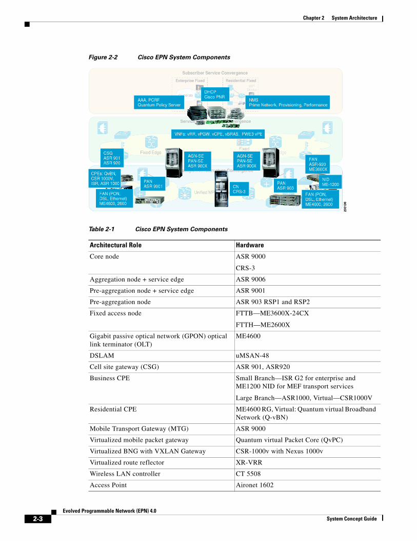
For each role in the architecture, the system selects devices from different Cisco product families to provide operators with the best-of-breed selection of fully interoperable products available in the market.
The various network components and their architectural role are described in Figure 2-2 and Table 2-1 on page 2-3.
2997
300
Subscriber Service Convergence
Consumer Convergence• Unified Subscriber Experience
Business Convergence:• Unified L3 VPN Experience• Seamless and Personalized BYODRemote Access and VPN Access
Unified MPLS TransportnV
MPLSEthernet
Integrated BNG,WAG, CGN
VNFs: vRR, QvPC-SI, QvBNCloud Policyand NMS
Service Infrastructure Convergence
Transport Infrastructure Convergence
nVMPLS
Ethernet
Enterprise FMC
CorporateIP
Mobile Device
Residential FMCWiFi
Device
IP
e
2-2Evolved Programmable Network (EPN) 4.0
System Concept Guide
Chapter 2 System Architecture
Figure 2-2 Cisco EPN System Components
Table 2-1 Cisco EPN System Components
Architectural Role Hardware
Core node ASR 9000
CRS-3
Aggregation node + service edge ASR 9006
Pre-aggregation node + service edge ASR 9001
Pre-aggregation node ASR 903 RSP1 and RSP2
Fixed access node FTTB—ME3600X-24CX
FTTH—ME2600X
Gigabit passive optical network (GPON) optical link terminator (OLT)
ME4600
DSLAM uMSAN-48
Cell site gateway (CSG) ASR 901, ASR920
Business CPE Small Branch—ISR G2 for enterprise and ME1200 NID for MEF transport services
Large Branch—ASR1000, Virtual—CSR1000V
Residential CPE ME4600 RG, Virtual: Quantum virtual Broadband Network (Q-vBN)
Mobile Transport Gateway (MTG) ASR 9000
Virtualized mobile packet gateway Quantum virtual Packet Core (QvPC)
Virtualized BNG with VXLAN Gateway CSR-1000v with Nexus 1000v
Virtualized route reflector XR-VRR
Wireless LAN controller CT 5508
Access Point Aironet 1602
2-3Evolved Programmable Network (EPN) 4.0
System Concept Guide

Chapter 2 System Architecture Transport Infrastructure
Transport InfrastructureIn the last two decades, SP network growth has occurred in an impromptu way. Operators have delivered new services by building a dedicated infrastructure requiring ad hoc technologies, protocols, and products. As a result, residential, business, and mobile services have been offered through separate networks, with dedicated resources and bandwidth.
As the rate of change is accelerating, a more strategic approach is required to cope with increased mobility, cloud services, and the exponential growth of either traffic or devices. Simplification, protocol reduction, intelligent linkages between network and applications, and greater efficiency must now drive the architectural choices.
Enabled by the Unified MPLS technology, the Cisco EPN System incorporates a network architecture designed to consolidate transport of fixed wireline and mobile services in a single network.
Such converged infrastructure must conform to the SLAs demanded by each of these services, ranging from resiliency requirements, to guaranteed bandwidth, to jitter and delay boundaries. Operations, Administration, and Maintenance (OAM) and Performance Management (PM) aspects, as well as granular QoS assurance, assume a pivotal role in these new networks and become key aspects the system fully integrates.
In addition, individual services pose unique challenges. Transport of mobile traffic requires timing distribution and synchronization across all radio equipment in the network. While a number of approaches are possible, including the setup of dedicated timing equipment in several locations in the network, the EPN System takes advantage of the network fabric as a timing transport infrastructure. By selecting a hybrid approach involving a combination of physical and packet-oriented technologies and a multi-layer hierarchy of clock functions optimally co-located with network equipment, the system is capable of delivering accurate frequency and time throughout the network.
Operational simplicity is tackled by introducing new automation models at all layers of the network, but especially in the access domains where operational efficiency plays a more critical role. Technologies like Autonomic Networking (AN) and Network Virtualization (nV) greatly reduce the number of touch points in each access domain, while Microwave Adaptive Code Modulation (ACM) correlation automatically recalculates QoS settings and forwarding paths based on a change in microwave link quality.
Inclusion of network function virtualization in the EPN System delivers the next level of network simplification. Stand-alone functionalities that do not play a critical role in the traffic data plane and in the network convergence can be extracted from the network devices and virtualized in the cloud, freeing up CPU cycles and memory resources for mission-critical applications on those nodes. Route reflector functions have historically been deployed on dedicated devices, away from data path and only establishing control plane adjacencies with the other network nodes, making them the ideal candidate for network virtualization at either the transport or service level. Under these premises, the EPN System focuses on moving Border Gateway Protocol (BGP) memory and processing requirements, as well as any resiliency concern, away from the network devices to a location, the data center, specifically designed to provide a large scale of computing power and memory and inherently resilient.
DHCP Server Prime Network Registrar
Policy Control, AAA QPS PCRF
Network Management System Prime Provisioning, Prime Performance Manager
Table 2-1 Cisco EPN System Components (continued)
Architectural Role Hardware
2-4Evolved Programmable Network (EPN) 4.0
System Concept Guide

Chapter 2 System Architecture Transport Infrastructure
Lastly, as providers convert more and more applications requiring multipoint communication to use a more efficient multicast transport, the industry expectation is that the infrastructure is capable of leveraging the intelligent replication logic built into multicast forwarding increases and becomes a requirement. The EPN System supports multicast delivered across all service categories from residential broadcast video to financial trading, to Evolved Multimedia Broadcast Multicast Service (eMBMS) for mobile, using a combination of multicast Label Distribution Protocol (mLDP) in the core and aggregation, and Protocol Independent Multicast (PIM) in the access network.
Unified MPLSUnified MPLS is the foundation upon which the EPN system was originally developed and continues to evolve today. It is an efficient MPLS-based transport that employs a hierarchical approach to solve scaling and convergence issues associated with a large-scale MPLS deployment, while ensuring end-to-end service provisioning and monitoring. End-to-end provisioning implies that service configuration should only happen at the service edges and nowhere else in the network. Similarly, end-to-end monitoring enables the use of service OAM and PM tools to evaluate the state of service "edge-to-edge."
MPLS is the clear winner as a technology that satisfies the requisites for convergence in Next Generation Networks (NGN) while preserving existing network investments. It supports legacy circuit (ATM/TDM) and packet-based (Ethernet) access technologies and easily enables virtualization of multiple services, including L2 and L3 VPNs, over a single infrastructure.
Still, in its simplest form, MPLS is a technology based on Interior Gateway Protocols (IGPs) and, as such, every node must be capable of reaching any other node in the network. When defining the extent of the MPLS domain, this ubiquitous connectivity requirement becomes a limiting factor, restricting the domain size to a thousand nodes or less (possibly requiring segmentation) and decreasing reliability and convergence times.
Breaking a MPLS cloud into multiple smaller domains has historically implied the loss of the end-to-end service-provisioning paradigm that made MPLS appealing in the first place, requiring services to be stitched somehow at each domain boundary.
Unified MPLS adopts a divide-and-conquer strategy where the core, aggregation, and access networks are partitioned in different MPLS/IP domains that are isolated at the IGP level, but still integrated via BGP labeled-unicast for the forwarding of unicast traffic.
Within each domain, LDP is used for label distribution to build intra-domain LSPs based on the interior routes. Partitioning these network layers into independent domains helps reduce the size of routing and forwarding tables on individual routers inside a domain, leading to better stability and faster convergence. This enables a device inside an access, an aggregation, or a core domain to have reachability via intra-domain LSPs to any other device in the same domain.
Reachability across domains is achieved using RFC 3107 procedures whereby BGP-labeled unicast is used as an inter-domain label distribution protocol to build hierarchical LSPs across domains. This allows the link state database of the IGP in each isolated domain to remain as small as possible, while all external reachability information is carried via BGP, which is designed to scale to the order of millions of routes.
The use of BGP throughout the Unified MPLS domain has the dual role of providing label distribution for inter-domain destinations, or service edges, as well as providing intelligent filtering mechanisms to enable the network to only learn what is needed, where it is needed, and when it is needed. By assigning role-based communities to routes advertised by the different nodes, it is possible to cleverly devise a route-learning logic on each node that only accepts communities and associated destinations that achieve the desired connectivity patterns.
2-5Evolved Programmable Network (EPN) 4.0
System Concept Guide

Chapter 2 System Architecture Transport Infrastructure
Redundancy at domain boundaries is achieved by interconnecting domains through pairs of either area border or AS boundary routers depending on the organizational structure of the administrative domain. Those nodes advertise in BGP the accumulated IGP metrics of all local inter-domain destinations, thus ensuring that reachability to those routes follows optimal paths in the network by selecting the best entry-point in a given domain under all conditions.
For the forwarding of multicast traffic, the core, aggregation, and access networks are currently integrated via recursive mLDP, whereas the system is already designed to incorporate future BGP labeled-multicast. With Recursive mLDP reachability to the multicast source is resolved at the edge of each domain and is represented by the local BGP next hop against which intra domain multicast forwarding paths are then built.
The network segmentation between the core and aggregation domains can be based on a single autonomous system (AS) multi-area design, or utilize a multi-AS design with inter-AS organization depending on the restrictions existing in different organizations.
The access domain can also be integrated in the overall architecture following different models varying according to the capabilities of existing network devices and the operator's history and preferences. The EPN System integrates three different access options.
• Existing installations already set up for L2-only Ethernet-based connectivity can seamlessly integrate into the Unified MPLS infrastructure as access circuits in the aggregation network border routers.
• IP-enabled access networks can benefit from extending Unified MPLS all the way to the access devices for superior route filtering and a cohesive transport paradigm throughout the network.
• Greenfield deployments may opt for a turnkey access solution that leverages the Cisco Satellite nV solution, which extends the Cisco ASR 9000 Series system capabilities beyond the physical chassis to control distant nodes that operate as remote virtual line cards.
Unified MPLS also distances itself from the traditional MPLS Fast Re-Route (FRR) technologies based on Traffic Engineered (TE) tunnels, which required manual setup of the protection mode and possibly the tunnels, toward totally automated mechanisms.
For intra-domain Label-Switched Paths (LSPs), Loop Free Alternate (LFA) and Remote LFA (rLFA) FRR are utilized for unicast MPLS/IP traffic in hub-and-spoke and ring topologies. LFA FRR technologies pre-calculate a backup path for every prefix in the IGP routing table, allowing the node to rapidly switch to the backup path when a failure occurs, providing recovery times on the order of 50 msec or less.
For inter-domain LSPs, network re-convergence is accomplished via BGP core and edge Prefix Independent Convergence (PIC) throughout the system. This allows for deterministic network re-convergence on the order of 100 msec, regardless of the number of BGP prefixes. BGP FRR technologies pre-calculate a loop free backup path for every prefix in the BGP forwarding table, and rely on the structure and entries in the Label Forwarding Information Base (LFIB) to allow for a fast transition to the alternate paths.
Transport Network ModelsThe Cisco EPN System framework is structured around the most common layers in SP networks: the access network, the aggregation network, and the core network. The supported transport architectures are arranged along two dimensions: the type of access and the size of the network. The type of access is divided into two categories:
• MPLS Packet Access:
– Covers point-to-point links, rings, and hierarchical topologies.
2-6Evolved Programmable Network (EPN) 4.0
System Concept Guide
Chapter 2 System Architecture Transport Infrastructure
– Applies to both fiber and newer Ethernet microwave-based access technologies with the MPLS access network enabled by the ANs.
– Both mobile and wireline services are supported and can be inserted at different levels in the network: directly at the last mile access nodes or backhauled deeper in the network for optimal service edge placement via a pseudowire-based transport.
• Ethernet/TDM Access/nV:
– Includes native Ethernet links in point-to-point or ring topologies over fiber and newer Ethernet microwave-based access. Ring topologies can be L3 enabled or L2-only with G.8032 protection
– Incorporates nV access, with satellite nodes connected to the hosts in ring topol-ogies or over any L2 transport (aka L2 fabric)
– Supports Central Office (CO) located PON optical link terminator (OLT) access.
– Covers point-to-point TDM+Ethernet links and Ethernet rings over hybrid mi-crowave access.
The MPLS services are enabled by the aggregation network and includes residential; business X-Line, E-LAN, and L3VPN; Mobile transport GSM Abis, ATM IuB, IP IuB, and IP S1/X2 interfaces. The size of the network is also classified into two categories:
• Small:
– Applies to network infrastructures in small geographies where the core and ag-gregation network layers are integrated in a single domain.
– The Single IGP/LDP domain includes less than 1000 core and AGN nodes.
• Large:
– Applies to network infrastructures built over large geographies.
– The core and aggregation network layers have hierarchical physical topologies that enable IGP/LDP segmentation.
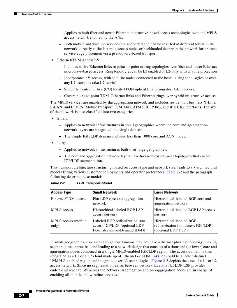
This transport architecture structuring, based on access type and network size, leads to six architectural models fitting various customer deployments and operator preferences. Table 2-2 and the paragraph following describe these models.
In small geographies, core and aggregation domains may not have a distinct physical topology, making segmentation unpractical and leading to a network design that consists of a thousand (or fewer) core and aggregation nodes combined in a single MPLS-enabled IGP/LDP region. The access domain is then integrated as a L1 or a L2 cloud made up of Ethernet or TDM links, or could be another distinct IP/MPLS-enabled region and integrated over L3 technologies. Figure 2-3 depicts the case of a L1 or L2 access network. Since no segmentation exists between network layers, a flat LDP LSP provides end-to-end reachability across the network. Aggregation and pre-aggregation nodes are in charge of enabling all mobile and wireline services.
Table 2-2 EPN Transport Model
Access Type Small Network Large Network
Ethernet/TDM access Flat LDP core and aggregation network
Hierarchical-labeled BGP core and aggregation network
MPLS access Hierarchical-labeled BGP LSP access network
Hierarchical-labeled BGP LSP access network
MPLS access (mobile only)
Labeled BGP redistribution into access IGP/LDP (optional LDP Downstream-on-Demand [DoD])
Hierarchical-labeled BGP redistribution into access IGP/LDP (optional LDP DoD)
2-7Evolved Programmable Network (EPN) 4.0
System Concept Guide

Chapter 2 System Architecture Transport Infrastructure
Figure 2-3 Small Network Architecture - Non-IP/MPLS Access, Flat LDP Core and Aggregation
In the case of MPLS Access, the access domain is comprised of a separate IGP and LDP domain. LDP is used to build intra-area LSPs within each segmented domain. The end-to-end network is integrated via either BGP labeled unicast, thus creating a hierarchy of LSPs for end-to-end label-based forwarding and a true unified MPLS transport, or via selective inter-domain route redistribution between domains, hence requiring service level forwarding lookups at the domain boundaries.
Also, label BGP is the only access allows for sophisticated and granular filtering of routes on a per-node basis, which makes it the technology of choice for a truly flexible and optimal placement of the service edge.
Figure 2-4 depicts and compares the two scenarios.
2932
04
Pre-AggregationNode
Pre-AggregationNode
Core andAggregation
IP/MPLS Domain
IGP/LDP Domain
Pre-AggregationNode
Pre-AggregationNode
TDM orPacket Microwave
Mobile Access Ethernet/SDH Fixedand Mobile Access
Pre-AggregationNode
Pre-AggregationNode
IGP Area
CoreNode
CoreNode
CoreNode
CoreNode
Ethernet(SDH)
2-8Evolved Programmable Network (EPN) 4.0
System Concept Guide

Chapter 2 System Architecture Transport Infrastructure
Figure 2-4 Small Network Architecture: IP-MPLS Access, Hierarchical-Labeled BGP LSP
Core-Aggregation, and Access
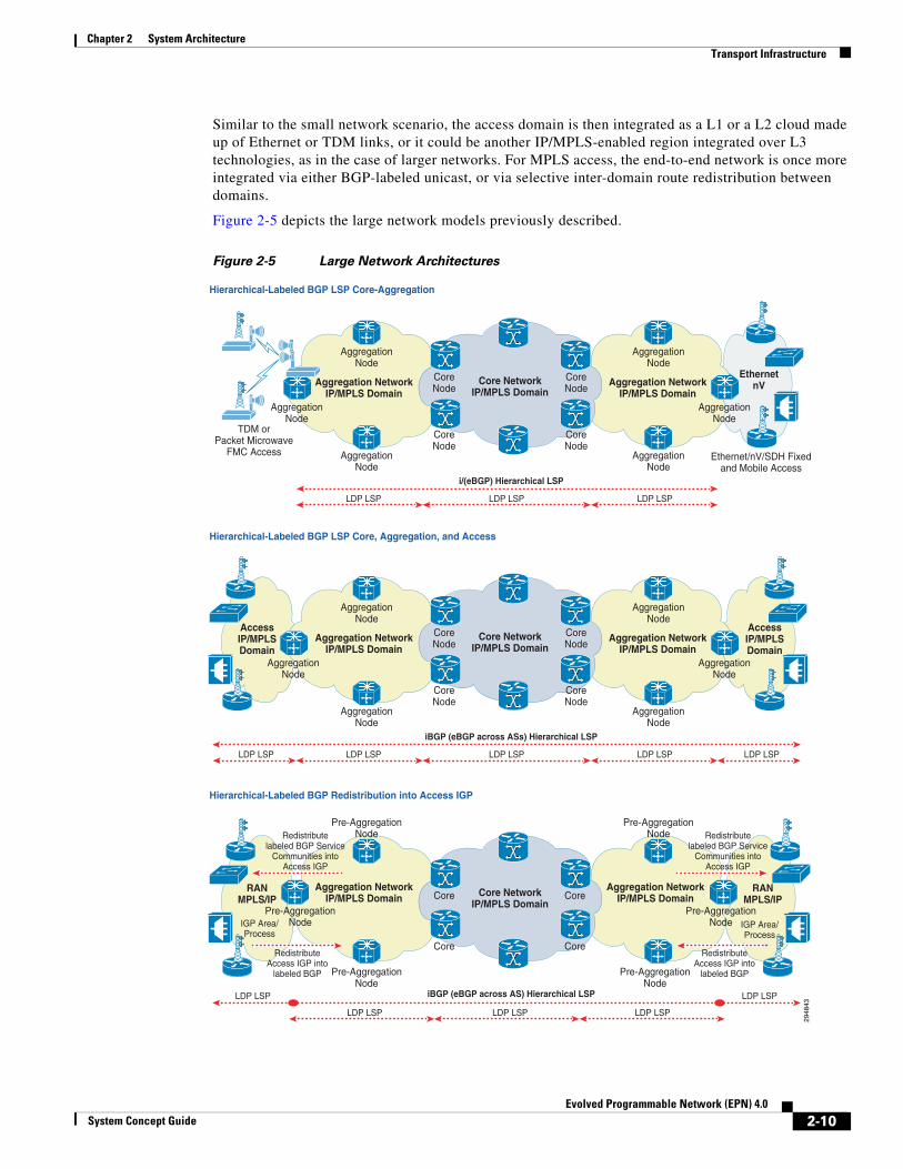
In medium-to-large geographies, a new level of segmentation is added in the network infrastructure by splitting the core and aggregation networks into independent IGP/LDP domains. LDP is used to build intra-area LSP within each segmented domain, while the aggregation and core networks are integrated with labeled BGP LSPs.
The segmentation between the core and aggregation domains can be based on a Single AS Multi-Area design, or utilize a multi-AS design with an inter-AS organization.
• In the Single AS Multi-Area option, the inter-domain nodes perform the BGP next hop self (NHS) function to extend the internal Border Gateway Protocol (iBGP)-hierarchical LSP across the aggregation and core domains.
• In the multi-AS scenario, a combination of iBGP and external Border Gateway Protocol (eBGP) peering is used for the exchange of the inter-domain routes within and between Autonomous Systems.
BGP community-based egress filtering is performed within the core network, so that the aggregation networks learn only the required remote destinations for mobile and wireline service routing, and all unwanted prefixes are dropped. This helps reduce the size of BGP tables on these nodes and also prevents unnecessary updates.
Pre-AggregationNode
Pre-AggregationNode
Core andAggregation
IP/MPLS Domain
iBGP Hierarchical LSP
Hierarchical-Labeled BGP LSP Core-Aggregation and Access
Labeled BGP Redistribution into Access IGP
Pre-AggregationNode
Pre-AggregationNode
Pre-AggregationNode
Pre-AggregationNode
LDP LSP
IGP Area
CoreNode
CoreNode
CoreNode
CoreNode
AccessIP/MPLSDomain
AccessIP/MPLSDomain
LDP LSP LDP LSP
2948
42
Pre-AggregationNode
Pre-AggregationNode
Core andAggregation
IP/MPLS Domain
iBGP Hierarchical LSP
Pre-AggregationNode
Pre-AggregationNode
Pre-AggregationNode
Pre-AggregationNode
Redistributelabeled BGP Service
Communities intoAccess IGP
RedistributeAccess IGP into
labeled BGP
LDP LSP
IGP Area
Redistributelabeled BGP Service
Communities intoAccess IGP
RedistributeAccess IGP into
labeled BGP
CoreNode
CoreNode
CoreNode
CoreNode
RANIP/MPLSDomain
RANIP/MPLSDomain
LDP LSP LDP LSP
2-9Evolved Programmable Network (EPN) 4.0
System Concept Guide
Chapter 2 System Architecture Transport Infrastructure
Similar to the small network scenario, the access domain is then integrated as a L1 or a L2 cloud made up of Ethernet or TDM links, or it could be another IP/MPLS-enabled region integrated over L3 technologies, as in the case of larger networks. For MPLS access, the end-to-end network is once more integrated via either BGP-labeled unicast, or via selective inter-domain route redistribution between domains.
Figure 2-5 depicts the large network models previously described.
Figure 2-5 Large Network Architectures
TDM orPacket Microwave
FMC Access Ethernet/nV/SDH Fixedand Mobile Access
EthernetnV
CoreNode
CoreNode
CoreNode
AggregationNode
AggregationNode
CoreNode
Core NetworkIP/MPLS Domain
i/(eBGP) Hierarchical LSP
Aggregation NetworkIP/MPLS Domain
AggregationNode
AggregationNode
AggregationNode
AggregationNode
Aggregation NetworkIP/MPLS Domain
LDP LSP LDP LSP LDP LSP
CoreNode
CoreNode
CoreNode
AggregationNode
AggregationNode
CoreNode
Core NetworkIP/MPLS Domain
iBGP (eBGP across ASs) Hierarchical LSP
Aggregation NetworkIP/MPLS Domain
AggregationNode
AggregationNode
AggregationNode
AggregationNode
Aggregation NetworkIP/MPLS Domain
AccessIP/MPLSDomain
AccessIP/MPLSDomain
LDP LSPLDP LSP LDP LSP LDP LSP LDP LSP
2948
43
Hierarchical-Labeled BGP LSP Core-Aggregation
Hierarchical-Labeled BGP Redistribution into Access IGP
Hierarchical-Labeled BGP LSP Core, Aggregation, and Access
Core
Core
Core
Pre-AggregationNode
Pre-AggregationNode
Core
Core NetworkIP/MPLS Domain
iBGP (eBGP across AS) Hierarchical LSP
Aggregation NetworkIP/MPLS Domain
Pre-AggregationNode
Pre-AggregationNode
Pre-AggregationNode
Pre-AggregationNode
Aggregation NetworkIP/MPLS Domain
RANMPLS/IP
RANMPLS/IP
LDP LSP LDP LSP
LDP LSP LDP LSP LDP LSP
IGP Area/Process
IGP Area/Process
Redistributelabeled BGP Service
Communities intoAccess IGP
RedistributeAccess IGP into
labeled BGP
Redistributelabeled BGP Service
Communities intoAccess IGP
RedistributeAccess IGP into
labeled BGP
2-10Evolved Programmable Network (EPN) 4.0
System Concept Guide
Chapter 2 System Architecture Transport Infrastructure
Transport Control PlaneThe Cisco EPN System proposes a RR design for setting up the Unified MPLS Transport BGP control plane. The RR approach is used to reduce the number of iBGP peering sessions within each domain in the EPN network.
While either inline or dedicated RR was promoted in prior revisions of the system, starting with Cisco EPN 3.0, the architecture is consolidated around centralized standalone RRs in the core and aggregation networks.
As discussed earlier in this chapter, this facilitates the virtualization of such functions into the data center, thus redirecting use of network device resources toward mission-critical tasks such as data packet processing and fast convergence.
Furthermore, explicit and built-in availability at the data center combine to enhance the resiliency aspects of RR functions. Explicit availability is achieved by emulating functional role redundancy as deployed in a physical infrastructure, thus instantiating pairs of virtual machines (VMs) acting as clustered RRs for a given network domain. Built-in availability leverages the orchestration and management mechanisms the cloud infrastructure has to offer to provide automatic restartability of failed VMs, periodic snapshots of VMs' health, and for transparent VMs' migration across data centers based on resource availability.
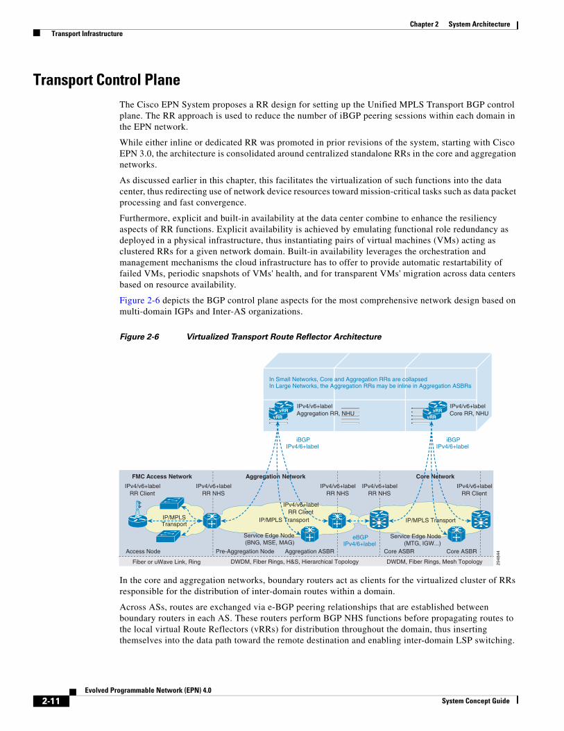
Figure 2-6 depicts the BGP control plane aspects for the most comprehensive network design based on multi-domain IGPs and Inter-AS organizations.
Figure 2-6 Virtualized Transport Route Reflector Architecture
In the core and aggregation networks, boundary routers act as clients for the virtualized cluster of RRs responsible for the distribution of inter-domain routes within a domain.
Across ASs, routes are exchanged via e-BGP peering relationships that are established between boundary routers in each AS. These routers perform BGP NHS functions before propagating routes to the local virtual Route Reflectors (vRRs) for distribution throughout the domain, thus inserting themselves into the data path toward the remote destination and enabling inter-domain LSP switching.
2948
44Pre-Aggregation Node Aggregation ASBR
DWDM, Fiber Rings, Mesh TopologyDWDM, Fiber Rings, H&S, Hierarchical TopologyFiber or uWave Link, Ring
Core NetworkFMC Access Network Aggregation Network
Core ASBRCore ASBR
IP/MPLS Transport
Access Node
IP/MPLS Transport
Service Edge Node(MTG, IGW...)
Service Edge Node(BNG, MSE, MAG)
iBGPIPv4/6+label
IP/MPLSTransport
IPv4/v6+labelRR Client
vRRvRR
iBGPIPv4/6+label
eBGPIPv4/6+label
vRRvRR
IPv4/v6+labelIPv4/v6+label IPv4/v6+label IPv4/v6+labelRR NHSRR NHS RR NHS
IPv4/v6+labelRR Client
RR Client
IPv4/v6+labelAggregation RR, NHU
IPv4/v6+labelCore RR, NHU
In Small Networks, Core and Aggregation RRs are collapsedIn Large Networks, the Aggregation RRs may be inline in Aggregation ASBRs
2-11Evolved Programmable Network (EPN) 4.0
System Concept Guide
Chapter 2 System Architecture Transport Infrastructure
Between the aggregation and the access domain, the area border routers (ABRs) still act as inline RRs to minimize the number of adjacencies the aggregation vRRs need to establish and maintain.
In the case of multi-domain IGPs in Intra-AS scenarios or in small networks based on a single IGP/LDP core and aggregation domain, the vRR design would apply to the core RRs only, while inline RRs are required at all the inter-domain boundary nodes, with the NHS function turned on to enable intra-domain forwarding of inter-domain traffic.
Route Scale ControlWhen designing a network comprised of thousands of nodes, the amount of reachability information each node must learn becomes a primary concern. Large forwarding tables tend to negatively affect network convergence time and require special consideration, while lower end devices, commonly deployed at the far edge of the network, may only have limited route capacity.
The principle that the network should learn only what is needed, where it is needed, and when it is needed must become the underlying guideline of any network design. Such a principle emphasizes how learning should be based exclusively on the connectivity requirements of each node based on the services it is meant to offer.
Services can be divided into two categories, based on the connectivity requirements between end points.
• Peering-based services—Demand any-to-any connectivity between users that are part of a common group. Such group can be then closed or open depending on the presence or absence of any barrier of ingress. Examples of peering-based services with closed and open user groups include Business L2/L3 VPNs and LTE X2, and Consumer Internet, respectively.
• Community-based services—Imply many-to-few connectivity between users that are part of a closed group. Most of the EPN connectivity requirements fall under this category, including consumer and enterprise data transport from access to retail and wholesale hand off points, and mobile interfaces such as Abis, Iub, and S1 as defined by the 3GPP specifications.
The BGP protocol enables intelligent filtering covering all models. By assigning role-based communities to routes advertised by the different nodes, it is possible to cleverly devise a route learning logic on each node that only accepts communities and associated destinations that achieve the desired connectivity patterns.
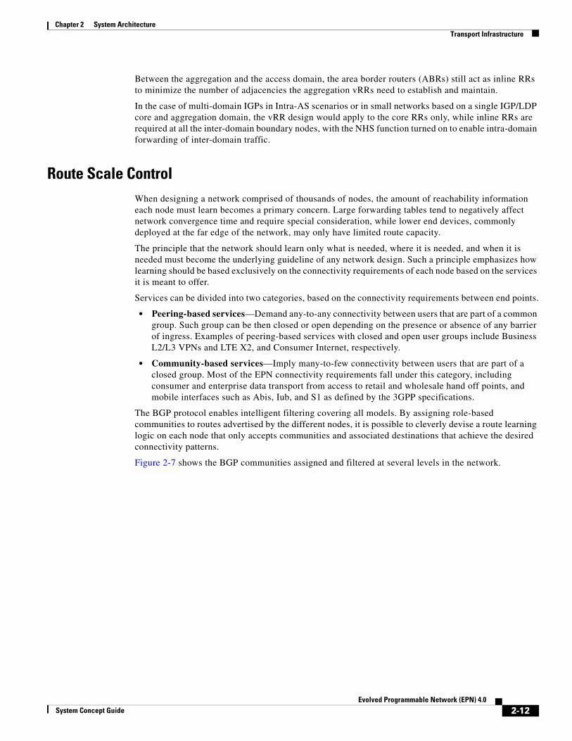
Figure 2-7 shows the BGP communities assigned and filtered at several levels in the network.
2-12Evolved Programmable Network (EPN) 4.0
System Concept Guide
Chapter 2 System Architecture Transport Infrastructure
Figure 2-7 Transport Routes Filtering Architecture
At a high level, the system defines the following role-based communities:
• Internet Gateway—Announcing reachability information to network nodes responsible to provide connectivity to the Internet. Imported by nodes requiring Internet connectivity.
• Mobile Service Edge—Announcing reachability information to network nodes responsible of providing connectivity to the Mobile Packet Core (MPC), also known as Mobile Transport Gateways (MTG). They are imported by nodes requiring communication to the mobile packet core, typically cell site routers.
• Fixed Service Edge—Announcing reachability information to network nodes implementing residential functions, such as Broadband Network Gateway (BNG), and multi-segment business services, such as business H-VPLS or pseudowire headend (PWHE) for L2 and L3 VPNs. They are imported by the Internet Gateway and by the other service edge fixed nodes.
• Global and Local Radio Access Node (RAN) and Fixed Access Node (FAN)—Announcing reachability information to network nodes in the access domains implementing mobile and fixed services, such as cell site routers (CSRs) and access nodes for business services. The global RAN community is common across all access domains and it is imported by the MTGs to gain reachability to all CSRs in the network. The local RAN community is unique for each access or each aggregation domain, depending on the route scale capabilities of the CSRs in those domains. Aggregation nodes and CSRs in neighboring domains import it to achieve direct inter-access and intra- or inter-aggregation domain communication for LTE X2 interfaces. Global and Local FAN communities are used for similar purposes.
All nodes in the network filter BGP communities in an inbound direction except for the core RR nodes, which filter the global RAN community from routing updates sent toward all peering node excluding the MTG gateways. The FANs further perform selective inbound prefix filtering of Virtual Private Wireline Service (VPWS) service end-point addresses. The setup of the filters is automated based on VPWS service activation.
2948
45
CSG
FTTB FTTB
CSG
CSG
IWGAGN-SE
CSG
iBGPIPv4+label
iBGPIPv4+label
iBGPIPv4+label
iBGPIPv4+label
iBGPIPv4+label
CN-RR
CN-ABRPANInline RR
PANInline RR
CN-ABR
Core NetworkIGP Domain
Access NetworkIGP Domain
Aggregation NetworkIGP Domain
Aggregation NetworkIGP Domain
Mobile AccessNetwork
IGP Domain
RR
Inbound FilterGlobal FAN, MSE, FSE
and neighbor RANs
BGP inbound route filter for mobile access:1. Accept MSE community (for LTE S1)2. Accept local and neighbor RAN communities for LTE X2 3. Drop
BGP inbound route filter for fixed access:1. Accept remote loopbacks for configured fixed services
(VPWS Transport to remote SEs or remote FANs)2. Drop
Inbound FilterGlobal FAN, MSE, FSE
and neighbor RANs
Inbound FilterGlobal FAN, MSE, IGW
Inbound FilterGlobal MSE, RAN
Inbound FilterGlobal FAN, MSE, IGW
Egress filter towardsALL BUT MTGs and 1.2PANneighbor-group: Drop global
RAN community
2-13Evolved Programmable Network (EPN) 4.0
System Concept Guide
Chapter 2 System Architecture Transport Infrastructure
MulticastThe Cisco EPN System supports services delivered via unicast transport as well as multicast. Multicast services include broadcast video for residential, eMBMS for mobile, and multicast-based applications for enterprise.
An operator's network may carry multiple multicast services concurrently on a single infrastructure, which requires proper transport organization in order to meet the different communication needs for the disparate services while providing the required separation at the same time.
While standard efforts exist to address transport of multicast services using multicast GRE (mGRE) tunnels and PIM, a more desirable approach aims to consolidate both unicast and multicast traffic forwarding on a common data plane based on label switched paths (LSPs). These new Label Switched Multicast (LSM) paths are created via multicast Label Distribution Protocol (mLDP), which provides extensions to LDP to enable the setup of multiprotocol LSPs (MP LSPs) without requiring additional multicast routing protocols, such as PIM, in the MPLS infrastructure. This addresses the setup of non-hierarchical intra-domain switching paths suitable for applications such as residential video services.
Contribution and distribution of residential video services involves a limited number of multicast groups and sources, thus only requiring a reasonably low number of LSM trees. A hierarchical approach, built upon LSP nesting to reduce the total number of LSPs and routes to multicast sources that each domain must maintain, may not be required and a flat architecture with redistribution of multicast source addresses across all domains might be acceptable.
Similarly, multipoint-to-multipoint business multicast VPNs have historically been centralized in the core domain, also requiring a flat LSP topology. However, the increased adoption of multicast VPN services suggests that the business edge will need to be further distributed in the near future, finally mandating a hierarchical LSP approach.
Although both IETF and Cisco are working to extend labeled BGP support to multicast traffic to create such hierarchical LSM transport, current solutions focus on enabling an end-to-end flat LSM tree across the unified MPLS domains without redistribution. RFC 6512, in particular, defines recursive mLDP behaviors to enable the creation of LSM paths when a given domain has no reachability to the multicast source or root node.
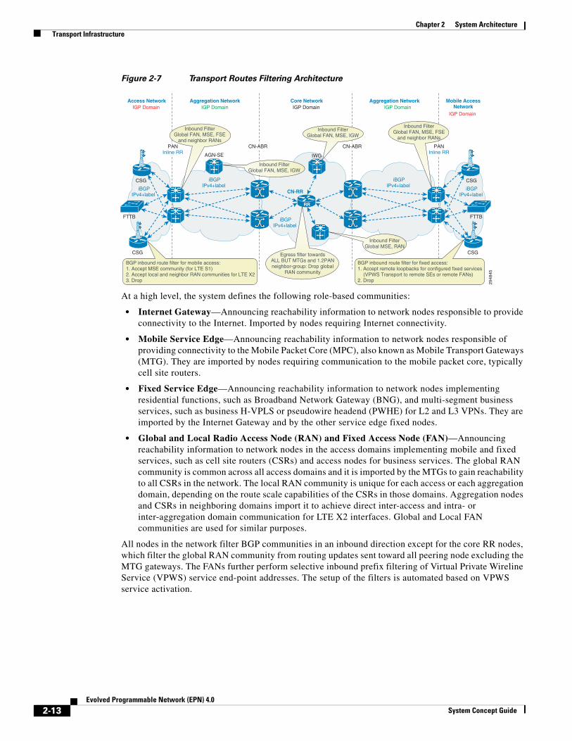
Figure 2-8 illustrates the end-to-end deployment of multicast transport implemented by the EPN System and based on RFC 6512.
Figure 2-8 Unified MPLS Multicast
2932
15
CoreNode
CoreNode
CoreNode
AggregationNode
AggregationNode
CoreNode
Core NetworkIP/MPLS Domain
BGP Hierarchical P2P LSP
Aggregation NetworkIP/MPLS Domain
AggregationNode
AggregationNode
AggregationNode
AggregationNode
Aggregation NetworkIP/MPLS Domain
AccessIP/MPLSDomain
AccessIP/MPLSDomain
Flat MP/P2MP LSM based on recursive mLDP
LDP LSPLDP LSP LDP LSP LDP LSP
Access PEmLDP request with Opaque TLVPointing to the BGP next hop for the spource Each ABR does a recursive lookup
LDP LSP
2-14Evolved Programmable Network (EPN) 4.0
System Concept Guide
Chapter 2 System Architecture Transport Infrastructure
Multicast service edge nodes add an additional opaque time-length-value (TLV) to the mLDP requests they originate, which includes the local BGP next hop used to reach the multicast source. LSMs within a domain are then built based on that BGP next hop. The recursive lookup continues at all domain boundaries until the multicast source is directly reachable from within the domain.
In the case of Layer 3 access, multicast source addresses are redistributed into the access network IGP according to the multicast address family, and PIM is enabled to build multicast delivery trees that are rooted at the redistribution nodes.
In the case of Layer 2 Ethernet access, IGMPv2/3 or MLDv2 snooping is enabled throughout the access domain to ensure optimal replication of multicast frames. In the case of nV access and Layer 1 ring topologies, the same is also achieved by offloading multicast replication at the satellite nodes.
Integration with Microwave ACMNearly half of all mobile backhaul access networks worldwide utilize microwave links, requiring the inclusion of microwave technology in the Cisco EPN System architecture. The EPN System integrates third party microwave outdoor units (ODUs) and radios in the access network to validate transport of traffic over microwave links, including such aspects as QoS, resiliency, OAM, and performance management. System efforts have focused on microwave equipment from NSN, NEC, SIAE, DragonWave, and Ceragon.
The typical deployment within the Cisco EPN architecture is to use the microwave gear to provide wireless links between cell site gateways (CSGs) over GbE connections. Since most microwave equipment used in this context supports sub-Gb transmission rates, typically 400 Mbps under normal conditions, certain accommodations must be made. Hierarchical QoS (H-QoS) policies should be implemented in the egress direction on either side of the microwave link, providing the ability to limit the flow of traffic to the bandwidth supported across the link, while providing PHB enforcement for expedited forwarding (EF) and advanced forwarding (AF) classes of traffic.
The microwave links are typically deployed in hybrid fiber-microwave rings that can be operated in a Layer 2 or a Layer 3 mode. The operational mode affects the failure protection mechanism used on the ring:
• Layer 2 Mode—The ring is protected by a ring protection protocol such as G.8032. A minimum of two instances is required to load balance traffic on both sides of the ring.
• Layer 3 Mode—IGPs are used for best path selection and re-routing around failures. IGP metrics should be adjusted to account for the microwave links deployment, allowing the IGP to properly understand the weights between true Gb links, and Gb ports connected to sub-Gb microwave links.
If the bandwidth provided by a microwave link was constant, then the switching path set up by G.8032 or the IGP weights and H-QoS shaper rates could be set once and perform correctly. However, the bandwidth supported at a given time by a microwave link depends upon environmental factors. Fog, rain, snow, or other weather can drastically affect the microwave link speed. To enable the microwave link to support the optimal amount of bandwidth for the current weather conditions, the equipment supports ACM functionality. ACM allows the radio equipment on either end of the microwave link to assess the current environmental conditions and automatically change the utilized modulation to provide the optimal amount of bandwidth for the given environment.
Regardless of the ACM status of the microwave link, the GbE connection to the ANs is constant, so the nodes are unaware of any changes to the bandwidth on the microwave link. To ensure that optimal routing and traffic transport is maintained through the access network, a mechanism is needed to notify the MPLS ANs of any ACM events on the microwave links. A new vendor-specific message (VSM) in Y.1731 allows for the microwave equipment to notify Cisco routers of ACM events, and the bandwidth available with the current modulation on the microwave link. Figure 2-9 shows the overview of ACM
2-15Evolved Programmable Network (EPN) 4.0
System Concept Guide
Chapter 2 System Architecture Transport Infrastructure
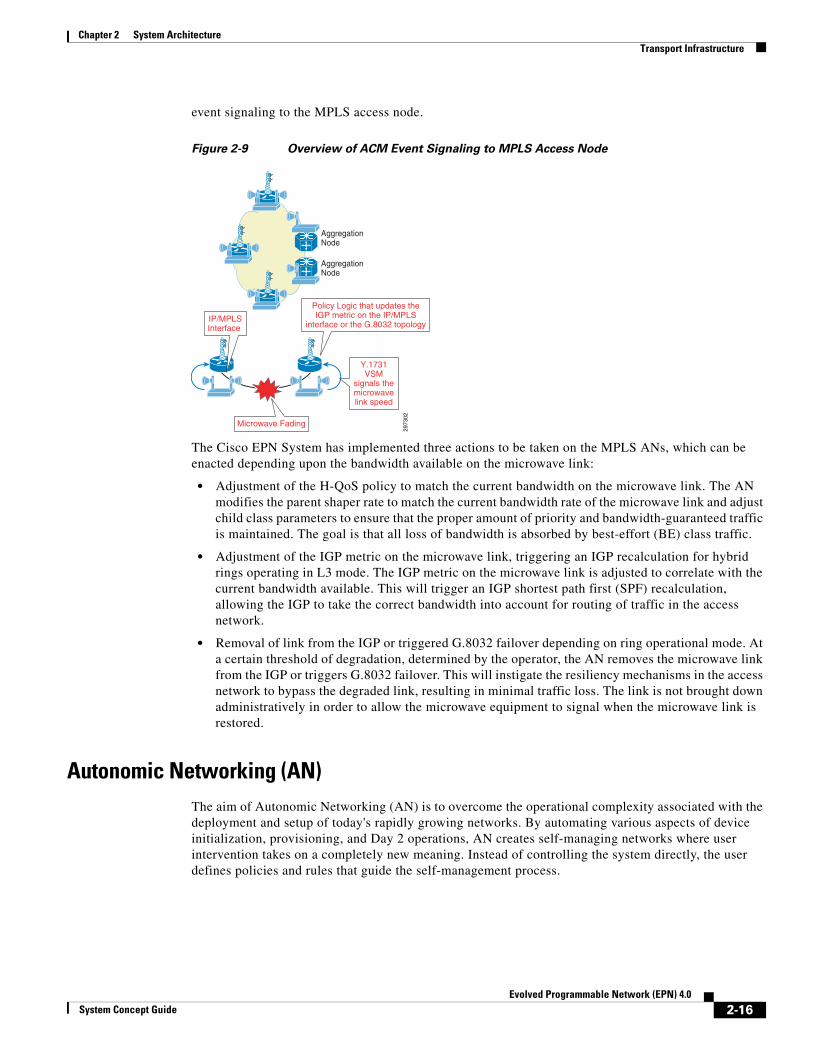
event signaling to the MPLS access node.
Figure 2-9 Overview of ACM Event Signaling to MPLS Access Node
The Cisco EPN System has implemented three actions to be taken on the MPLS ANs, which can be enacted depending upon the bandwidth available on the microwave link:
• Adjustment of the H-QoS policy to match the current bandwidth on the microwave link. The AN modifies the parent shaper rate to match the current bandwidth rate of the microwave link and adjust child class parameters to ensure that the proper amount of priority and bandwidth-guaranteed traffic is maintained. The goal is that all loss of bandwidth is absorbed by best-effort (BE) class traffic.
• Adjustment of the IGP metric on the microwave link, triggering an IGP recalculation for hybrid rings operating in L3 mode. The IGP metric on the microwave link is adjusted to correlate with the current bandwidth available. This will trigger an IGP shortest path first (SPF) recalculation, allowing the IGP to take the correct bandwidth into account for routing of traffic in the access network.
• Removal of link from the IGP or triggered G.8032 failover depending on ring operational mode. At a certain threshold of degradation, determined by the operator, the AN removes the microwave link from the IGP or triggers G.8032 failover. This will instigate the resiliency mechanisms in the access network to bypass the degraded link, resulting in minimal traffic loss. The link is not brought down administratively in order to allow the microwave equipment to signal when the microwave link is restored.
Autonomic Networking (AN)The aim of Autonomic Networking (AN) is to overcome the operational complexity associated with the deployment and setup of today's rapidly growing networks. By automating various aspects of device initialization, provisioning, and Day 2 operations, AN creates self-managing networks where user intervention takes on a completely new meaning. Instead of controlling the system directly, the user defines policies and rules that guide the self-management process.
2973
02
AggregationNode
AggregationNode
IP/MPLSInterface
Microwave Fading
Policy Logic that updates theIGP metric on the IP/MPLS
interface or the G.8032 topology
Y.1731VSM
signals themicrowavelink speed
2-16Evolved Programmable Network (EPN) 4.0
System Concept Guide

Chapter 2 System Architecture Service Infrastructure
The first phase of the AN focuses on providing an infrastructure that allows for automatic bootstrap of nodes in the network through the establishment of the AN Virtual Out-of-Band Communication Channel (VOBC). The goal is to achieve minimal dependency on human operators as well as on centralized network management components. Autonomic devices are "intelligent"—they are self-aware and discover the network around them to determine their respective position and role.
The VOBC is automatically established across all nodes in the access network without any required configuration or user intervention and provides full reachability between autonomic nodes that are part of the same domain. It relies on adjacency discovery across neighboring nodes, which is enabled by the use of IPv6 link local unicast and multicast addresses and dedicated VLANs.
Once an adjacency has been established, a new device attempting to join the AN sends its vendor-based credentials to the neighbor, which acts as proxy toward the Registrar Authority Gateway and extends the VOBC IPv6 address space over GRE tunnels. The Registrar is a domain-specific registration authority that connects to AAA, Syslog and TFTP servers, and the operator's Network Operation Center (NOC) to validate devices' identities and to make policy decisions including authorization of the new device to join the domain.
Once the node is authorized, it automatically downloads its configuration from the TFTP server to complete its provisioning. This eliminates the need for field technicians to have any knowledge of device configuration when bringing up new nodes in the network.
Once the node is fully provisioned, IPv4 address assignment in the access ring is further automated by the use of Auto-IP, which enables two nodes on a link to negotiate their respective addresses. Auto-IP allows for seamless insertion, removal and reordering of nodes in a ring without any configuration change due to manual address re-assignment.
Figure 2-10 illustrates the high-level architecture of the AN network implemented by the EPN System.
Figure 2-10 Autonomic Networking Architecture
Service InfrastructureThe Service Infrastructure layer of the Cisco EPN System focuses on the deployment and implementation of a full set of services offered by operators, ranging from the basic transport of raw data in Metro Ethernet Forum (MEF) and Mobile Transport services, to the better differentiation opportunities of Consumer and Enterprise services. The Service Infrastructure layer also introduces the next level of convergence in the architecture.
Unified MPLS Transport
2973
03
AN PAN
AN Discovery Enabled
AAA
Syslog
TFTP HostingUMPLSConfigurations
TFTP the AN Node Configuration
ANRAGateway
AN FMCAccess Node
AN ConnectedNMS LAN
Auto-IP
AN Virtual Out of BandCommunication Channel
AN VOBC extendedover GRE Tunnel
2-17Evolved Programmable Network (EPN) 4.0
System Concept Guide
Chapter 2 System Architecture Service Infrastructure
From a service standpoint, the meaning of convergence is multi-fold. Convergence may happen at different levels of the service infrastructure, from the network functions, to subscriber management, to access technology agnosticism, and can be achieved by network integration or network function virtualization (NFV) in computing resources.
Integrated Network Functions refer to those functionalities that are optimally embedded in the network transport devices to optimize traffic patterns while reducing power consumption and real estate requirements through consolidation.
The additional computing capacity and better hardware performances of today's equipment have made multi-service capabilities within a single network node possible. Consolidation of functionalities enables economies of scale by decreasing the infrastructure, either installed base or spares. By lowering the power consumption, CAPEX and OPEX are inevitably reduced. In addition, consolidation of transport and service functions within a single device allows for an optimal placement of the customer service edge based upon customer distribution, which, in turn, results in a better use of network resources as well as an improved service experience to the end user.
Integrated network functions in EPN System include Virtual Private Network Layer 2 and Layer 3 service edge, Broadband Network Gateway (BNG), Carrier Grade Network Address Translation (CG NAT or CGN), and Wireless Access Gateway (WAG).
Virtualized Network Functions refer to capabilities that are better accomplished when consolidated on standard high volume servers, which could be centralized in data centers or distributed within the network nodes. This typically refers to functionalities with high processing and memory requirements that could benefit from leveraging existing resources available in a data center, or that normally require long development cycles because of operational constraints, such as hardware or software upgrades throughout the network.
Virtualized Network Functions in the EPN System consist of:
• Virtualized subscriber aggregation functions in the data center, which comprise of a Broadband Network Gateway (BNG) for consumer services for PPPoE subscribers and of a Mobile Packet Gateway (PGW) function for mobile access for enterprise and consumer services.
• A virtualized Provider Edge (vPE) node that achieves full virtualization of the service edge functions for managed services hosted at the operator's regional or national data centers.
• A virtualized VXLAN gateway and virtual switch functions that complement the architecture for virtualized subscriber aggregation functions by acting as a VXLAN tunnel terminator providing a VLAN hand-off toward the virtualized BNG function.
• A virtualized hierarchy of RR for the advertisement of service-specific routes.
• Virtualized Customer Premises Equipment (vCPE) functions for both residential and business services. CPE functions hosted on these distributed servers, either located at the enterprise premises for business or at the access nodes for residential, are complemented further by value-added functionalities the operator can upsell and distribute, such as storage space to the residential user or managed services to the enterprise.
For the management of residential users and enterprise customers, the EPN System promotes a converged Policy and Charging Rules Function (PCRF) to offer a consolidated experience across fixed, mobile, and Wi-Fi access, where applicable. The PCRF function is virtualized in the data center and uses standard interfaces to communicate with the various Policy Enforcement Points throughout the network.
Lastly, all EPN services are supported across a combination of access technologies that include Native Ethernet and MPLS Access. Native Ethernet access is further segmented as in traditional Ethernet access network design and network virtualization, depending on the operational mode in which the access devices are managed.
The following sections describe in detail the various services the EPN transport supports:
2-18Evolved Programmable Network (EPN) 4.0
System Concept Guide

Chapter 2 System Architecture Service Infrastructure
• Consumer Services—Residential wireline (PON, DSL), Wi-Fi, and mobile data.
• Enterprise Services—L3VPNs over fixed and mobile access.
• MEF Transport Services—L2VPNs as defined by the MEF for transparent site-to-site connectivity (E-Line, E-LAN, and E-Tree) and E-Access.
• Mobile Transport Services—Backhaul services for 2G and non-IP 3G technologies over structured and unstructured emulated circuits and IP 3G and 4G technologies over L3VPNs.
Consumer ServicesIn the last decade, the general perception of what consumer services entails has experienced a shift. What used to be triple play offerings (voice, video, and data) at the subscriber premises has now become ubiquitous access from any device and location to any content in the network with a cohesive quality of experience.
To cater to those needs, the EPN System has developed an architecture capable of integrating subscriber access over a number of different access media, and providing a unified subscriber experience leveraging a converged PCRF across all types of access and service edge nodes.
As shown in Figure 2-11, the architecture is designed to support consumer services through wireline, Wi-Fi, and mobile access over a unified MPLS network.
Figure 2-11 Consumer Services Architecture
While mobile data is a practical answer to the immediate demand for pervasive on-the-go access, operators are looking at Wi-Fi for a more cost-effective alternative. Wi-Fi has become ubiquitous in nearly all personal mobile devices and has the ability to outperform 4G networks. Additionally, close
2973
04
Pre-Aggregation NodeASR-903, ASR-9001
DWDM, Fiber Rings, Mesh TopologyDWDM, Fiber Rings, H&S, Hierarchical TopologyFiber or uWave Link, Ring
Core NodeCRS-3
Core NodeCRS-3
IP/MPLS Transport
UMTS, LTE, WiFi
IP/MPLS Transport
ResidentialDSL Homes
ResidentialCommunity WiFi
ResidentialPON Homes
Aggregation NodeASR-9000
vCPE
RADIUS,DiameterG.8032
PONAccess
DSLAccess
IP/MPLS orEthernet Transport
Legacy PPPoEDSL Homes
Aggregation NodeASR-9001, 9006
Unified MPLS Network
IntegratedvVXLAN GWand vBRAS
FMC Policy System
PGW
AGN-SE with BNG SRG, WAG Ethernet G.8032 and vCPEs
AGN-SE with BNG SRG,WAG, PWHE
• DSL, PON, WiFi, LTE FMC Access• MPLS or Ethernet Transport• WAG Walk By Sessions• BNG PWHE, SRG• vEPC• vCPE
PWE3PWE3
E0MPLS PW forPPPoE session
VXLANFabric Path
2-19Evolved Programmable Network (EPN) 4.0
System Concept Guide

Chapter 2 System Architecture Service Infrastructure
alignment with wireline architectures makes it even more desirable to those seeking a converged infrastructure. Carrier-grade Wi-Fi, therefore, has become a central element in the EPN System's strategy to offer ubiquitous capacity and coverage to both fixed and mobile operators. While the Cisco Service Provider Wi-Fi solution targets Metro and Hot-Spot Wi-Fi architectures, the EPN System expands into the residential areas, with community Wi-Fi and the consolidation of residential and wireless aggregation functions in the same service edge node.
By consolidating different access media over the same transport infrastructure, the service edge can be optimally placed not only based on subscriber distribution for a specific access type, but also across access media, thus giving SPs the ability to provision subscribers, bandwidth, and service access, according to the specific patterns of their networks.
Under these premises, wireline and Wi-Fi access gateway functions can coexist within the same node and take advantage of the multi-service capabilities that the additional computing capacity and the better hardware performances of today's equipment have made possible. These new models simplify the architecture and reduce costs by eliminating application-specific nodes and consolidating transport and multiple service edge functions within a single device.
Subscriber aggregation over wireline architectures is supported via Ethernet and MPLS access, which further improves flexible positioning of the consumer service edge.
The readiness of fiber-based access and the consequential increase of bandwidth availability at the last mile have driven a steep rise in the number of subscribers that can be aggregated at the access layers of the network. New Ethernet-based access technologies such as PON allow for the aggregation of thousands of subscribers on a single access node, with per-subscriber speeds that average 20 Mbps, further justifying the placement of subscriber management functions as close as possible to the subscriber-facing edge of the network to satisfy scale and total bandwidth demands. Depending on the speed offered to the consumer, the level of oversubscription each operator is comfortable in deploying, and ultimately the subscriber density at each POP, the connectivity between the PON access nodes and the BNG is modeled in a hub-and-spoke topology, with dedicated interfaces per access node at the BNG, or as rings of access nodes, which only require a pair of interfaces typically on different BNGs. Rings are open, suggesting they are also terminated at the BNGs, and are G.8032-protected to ensure sub 50ms failover time.
At the same time, the economy of scale and incumbency of legacy access technologies such as DSL, which is characterized by limited bandwidth and subscriber fan out at the access node, mandate the consolidation of subscriber management functions deeper in the network. To cater to those needs while guaranteeing Layer 2-like connectivity between subscribers and subscriber management devices over a scalable transport infrastructure, the traditional access network design based on a flat Layer 2 domain is abandoned in favor of a more flexible MPLS access, thus adding residential to the list of services already offered over such transport. In this model, residential traffic is carried in Ethernet pseudowires that a PWHE function enabled at the BNG terminates. The BNG serves as the injection point for all the subscriber management logic.
The following sections provide additional details specific to each access method.
Consumer Wireline Access
For the aggregation of residential wireline subscribers, the EPN System fully aligns to well-established 1:1 and N:1 subscriber aggregation models, and extends their support over either a traditional Ethernet or a more flexible MPLS access to ensure optimal placement of the service edge regardless of the operator's preferred deployment model.
Subscriber access is implemented via IP over Ethernet (IPoE) for providers who favor a cohesive transport across all residential services and between residential, business, and mobile applications, or through legacy Point-to-Point Protocol over Ethernet (PPPoE) for those who desire stronger subscriber
2-20Evolved Programmable Network (EPN) 4.0
System Concept Guide
Chapter 2 System Architecture Service Infrastructure
authentication mechanisms or have long lasting incumbency of PPPoE. Moreover, for operators who have fully transitioned to IPoE for next generation services, but still retain a small customer base of PPPoE subscribers with low to mid internet speed access requirements, the EPN system proposes a virtualized approach to the subscriber concentrator node with BNG PPP Termination Aggregation (PTA) functions centralized and virtualized in the operator's data center. Subscriber PPPoE sessions are dynamically tunneled between an access concentrator, residing in the service edge node in the pre-aggregation or aggregation domain, and a tunnel tail-endpoint, which is also virtualized in a virtual VXLAN Gateway.
End-to-end tunneling is fully orchestrated and accomplished by a combination of technologies:
• An EoMPLS pseudowire per DSLAM running between the access concentrator and the Data Center Gateway (DCG) and
• A VXLAN tunnel between the DCG and the virtualized VXLAN Gateway.
Tunnels are stitched at the DCG. Different S-VLANs between the VXLAN GW and the virtualized BNG function allow for the identification of the original subscriber’s DSLAM. The use of VXLAN-based tunneling within the data center ensures transparency of subscriber’s MAC addresses up to the vBNG, thus preventing any potential issue related to MAC tables scale in the data center switches. Traffic from the vBNG to the interned gateway and subscriber management servers follows the data center implementation guidelines defined by the Virtualized Multiservice Data Center (VMDC) System and uses Fabric Path technology. Further information on the VMDC system can be found at the following location:
• http://www.cisco.com/c/en/us/solutions/enterprise/data-center-designs-cloud-computing/landing_vmdc.html.
At the network layer, the system provides complete migration solutions from IPv4 to IPv6. Depletion of the IPv4 address space has been an area of concern for operators for several years. Techniques such as network address translations of IPv4 address (NAT44) have been widely deployed in order to reduce the number of globally-routable addresses assigned to subscribers. However, law enforcement regulations mandating the ability to identify a subscriber univocally by his or her IP address have largely limited the effectiveness of these techniques in certain countries.
With IPv6 reaching maturity, an increasing number of providers are actively looking at turning on IPv6 access to subscribers. The migration, however, can't be instantaneous. A number of network services are still offered exclusively via IPv4, making a coexistence model and a step-by-step migration necessary.
• For the transport of unicast services and virtualized BNG functions, the system focuses on the support of single stack IPv4 PPPoE sessions.
• For the transport of unicast services and network, integrated BNG functions the system presents operators with the following choices:
– An IPv4-only or a Dual Stack UNI, with support for CG NAT and dual-stack subscriber enablement at the BNG. This model allows for a phased transition to IPv6, by upgrading the BNG while retaining support for legacy IPv4-only UNIs on portions of the network that have not yet been updated to IPv6.
– A IPv6-only UNI with optional MAP-T functions enabled at CPE and BNG nodes and single-stack IPv6 subscribers at the BNG.
In the case of an IPv6-only UNI, IPv4-capable household devices (single or dual stacked) are granted end-to-end connectivity through mapping of address and port using translation (MAP-T) functions performed at the residential CPE and at the BNG device. Among the various NAT464 (IVI) technologies, the EPN System selects MAP-T because of its simplicity, transparency, and effective IPv4 address savings. By not requiring that network equipment keeps stateful IVI translation entries, it optimizes
2-21Evolved Programmable Network (EPN) 4.0
System Concept Guide

Chapter 2 System Architecture Service Infrastructure
resource utilization and performances, while an intelligent translation logic preserves the packet's original source and destination ports and addresses information, allowing for effective QoS and security applications throughout the network.
Within the core network, Unified MPLS offers seamless transport for both address families, fully separating IPv6 enablement in the residential access from the IPv4 core transport.
In regard to multicast and considering the fairly early stage of development of consumer IPv6-enabled multicast applications, the EPN System has chosen to continue supporting the delivery of multicast services to consumers via IPv4, while also introducing IPv6 to cater to those operators who have already gone through a full migration.
For core transport, as discussed earlier, the system leverages either MLDP MVPNs with BGP-based signaling or global transport with inband signaling of customer multicast routes to build multicast delivery trees that provide dense connectivity to all BNG nodes in the network and will reflect the few-to-many nature of video distribution in residential networks.
Lastly, EPN System introduces the integration of residential CPE functions with the access nodes. In this new model, all the core functionalities of a residential gateway are virtualized on an x86-based computing resource that is integrated with the access node. Such placement, compared to a data center-based implementation, ensures close alignment with established access architectures allowing CPE virtualization to be inserted in existing networks without disruption. The physical CPE at subscriber premises is left to provide only basic L2 connectivity between the subscriber household appliances and its virtualized counterpart in the operator's POP.
In addition to the existing residential gateway functions, this distributed cloud computing resource can be leveraged for effective co-location of consumer cloud-based services, such as storage space for data safekeeping or parental control.
In this context, virtualization of network functions is not about CAPEX and OPEX savings to any great extent. While the highly simplified management of these historically dispersed devices from a central place that is under full control of the operator reduces OPEX, the greatest benefit is an increased velocity of time to market for residential applications and a rationalization of the typical network operator cycle of innovation. Economies of scale required to cover investments in new functionalities in such distributed appliances are no longer applicable for software-based centralized development, making innovation possible and agile. Services can be rolled out quickly and can be scaled or reduced easily depending on the degree of acceptance.
Consumer Wi-Fi Access
Increase in mobile data traffic, lack of radio spectrum and coverage, and the attractive economy of offload have brought a need for incorporating small cell solutions into network infrastructure plans. Those solutions include licensed and unlicensed spectrum and technologies, such as Femto and Wi-Fi small cells.
With availability in nearly all personal mobile devices, including smartphones, tablets, cameras, and game consoles, Wi-Fi has become a central element in the Cisco EPN System strategy for ubiquitous capacity and coverage.
For the aggregation of consumers via Wi-Fi access, the EPN System complements traditional wireline connectivity with the enablement of community Wi-Fi on the wireline CPEs.
In this model, operator-owned residential CPEs announce public and private Service Set Identifiers (SSIDs). Private SSIDs are used by members of the household, while public SSIDs are well known among all customers of the same operator. The private SSID uses Wi-Fi Protected Access (WPA)/WPA2 security protocols in order to secure communication for the household equipment, while the public SSID is open. Public access is authenticated via web logon procedures or transparently using dynamically learnt network identities associated with the connecting device (e.g., MAC address).
2-22Evolved Programmable Network (EPN) 4.0
System Concept Guide
Chapter 2 System Architecture Service Infrastructure
Flexible and optimal positioning of the wireless gateway function is achieved by logically segmenting transport of household and public Wi-Fi traffic within the access network. Such segmentation has the advantage of simplifying H-QoS modeling for aggregated rate limiting based on the service category (pure residential wireline vs. public Wi-Fi) and allows for independent positioning of the wireline and Wi-Fi service edge, if desired. The EPN System, however, promotes a converged service edge, which takes into account the operator's need for cost optimization. It is also fully enabled by the scale, performances, and capabilities of the deployed devices.
Opening network nodes to Wi-Fi users may result in handsets automatically connecting to the open SSID and creating subscriber sessions at the aggregation nodes without the end users' explicit intent. Those sessions, known as walk-by sessions, are non-revenue generating, thus undesirable to the operator. While the existence of these sessions is intrinsic to any Wi-Fi deployment that uses open SSIDs, the EPN System is capable of nullifying their harmful consequences by ensuring access from legitimate users is never impaired.
Connectivity over the public Wi-Fi network happens preferentially over IPv4. While IPv6 access is also possible, IPv6-capable operative systems and applications in handsets have just started making their appearance in the market, sanctioning IPv4 as the existing leading address family in the space.
In the aggregation and core network, the same level of segmentation between pure residential and public Wi-Fi traffic can be achieved by isolating community Wi-Fi services in a dedicated L3 VPN through the virtualization means enabled by Unified MPLS.
Consumer Mobile Access
For locations where the offload of mobile data to a Wi-Fi network is not available, the Cisco EPN System integrates with the Cisco Integrated Service Provider + Enterprise Mobility (ISEM) system to incorporate and promote subscriber access over a mobile access network, thus delivering operators with a complete range of access options.
The Cisco ISEM system provides the radio access and the signaling functions for the setup of the mobile session, while the EPN System focuses on the management of the subscriber session and the virtualization of the PGW functions in the data center.
The subscriber experience in the case of a mobile type of network access is then personalized and unified to that of a wireline or a Wi-Fi-based access through homogeneous policy definitions and a common subscriber policy repository for a fully consolidated and ubiquitous data connection.
Enterprise Service ModelsFor enterprise service, the Cisco EPN System expands and innovates around well-established L3VPN technologies.
While offering a complete L3 VPN solution that consists of full support for IPv4 and IPv6 address families, unicast and multicast applications, SLA enforcement and monitoring and high availability, the system innovates by expanding the L3VPN reach into the enterprise with new access options, by extending business addressability to new user segments, and by developing new monetization opportunities. Figure 2-12 illustrates the enterprise services architecture.
2-23Evolved Programmable Network (EPN) 4.0
System Concept Guide

Chapter 2 System Architecture Service Infrastructure
Figure 2-12 Enterprise Services Architecture
As legacy WAN technologies such as ATM and Frame Relay have failed to deliver the increased bandwidth and enhanced performances required by today's applications, the system consolidates on Ethernet access to deliver the next wave of enterprise services.
With a combination of new OAM tools and fast convergence technologies able to guarantee sub-50msec convergence, Ethernet has evolved to become a suitable technology for carrier grade applications. Moreover, thanks to the variety of topologies in which it can be deployed, Ethernet allows operators to design and dimension the network according to the expected business growth in a specific geographical area. Hub-and-spoke topologies are ideal for large aggregation areas with high density POPs and high bandwidth demands, while more sparse environments and lower speed requirements may benefit from access ring topologies that link together a number of smaller size access nodes over high bandwidth uplinks. The EPN System incorporates both kinds of access topologies over first miles technologies that encompass Fiber To The Business (FTTB) and PON, and ensures service resilience through dual homing technologies that include Multi Chassis Link Aggregation (MC-LAG) and G.8032-protected ring topologies.
As operators grow more and more concerned about the operational costs and challenges of managing the increasing number of access nodes enabled by the bandwidth availability and cost effectiveness of these new Ethernet-based access networks, the system introduces a new operational paradigm. Without altering connectivity across devices in the access domain, the EPN System introduces support for network virtualization, thus enabling the service edge node to remotely control and configure the disparate access nodes as if they were local Ethernet cards. On this basis, the appeal of nV is even greater in deployments involving rural areas, where network equipment has been historically difficult to access and manage, allowing the provisioning of several remote nodes from a single touch point.
While a Native Ethernet access is offered to accommodate operators looking for capping existing investments and is a stepping stone toward migration to a packet-switched network architecture, the system promotes MPLS access to those operators already seeking to deploy a truly converged architecture to transport all service types with a uniform control plane and without compromising around optimal placement of the service edge.
Hypervisor
Hypervisor
VRFVPE
VRF VRF
VMVM VM
2948
49
Pre-Aggregation NodeASR-903, ASR-9001
DWDM, Fiber Rings, Mesh TopologyDWDM, Fiber Rings, H&S, Hierarchical TopologyFiber or uWave Link, Ring
Core NodeCRS-3
Core NodeCRS-3
IP/MPLS Transport
UMTS, LTE, WiFi
IP/MPLS Transport
RemoteBYOD User
(v)MPC (S/PGW)
MPLS over GRE betweenDCGs and vPE-Fs
Aggregation NodeASR-9000
BGP VPN AFI
IP/MPLS orEthernet Transport
Ethernet and nV
vSOC
VV
VVV
Enterprise
Enterprise SSID VLANs
Enterprise
EnterpriseMPLS VPN with Hierarchical VPN Extension DC
S1 and X2 L3 VPN
BridgedWiFi Access
Enterprise
EnterpriseEnterprise
Aggregation NodeASR-9001, 9006
DC Transport GatewayASR-9000
vMPC (LMA_EPC)
DCG (Hierarchical VPN, withVRF default route inject towardsvPEs provisioned by vSOC)
RemoteBYOD User
Ethernet PWE3
PAN-SE, AGN-SEwith WAG
EPN vRR NFV vRR
Branch GTPBearer
2-24Evolved Programmable Network (EPN) 4.0
System Concept Guide

Chapter 2 System Architecture Service Infrastructure
Since the scalability characteristics in terms of the number of VRFs and the number of prefixes in each VRF location make placing the L3VPN service edge on the access nodes impractical, the MPLS access enables extension of the L3VPN service into the aggregation nodes via a combination of Ethernet pseudowire emulation end-to-end (PWE3) as transport and PWHE functionality as a service injection point. PWHE is a technology that allows termination of access PWs into the L3 domain, VRF or global. The combination of the PW-based transport and the PWHE function at the service edge is an easy and scalable mechanism for tunneling customer traffic into a common IP/MPLS network infrastructure while applying all service-related functions at a more convenient location in the network.
The delivery of multicast traffic is optimized by the establishment of multipoint-to-multipoint (MP2MP) trees that are built on a per-Enterprise VPN basis and that are multidirectional and selective in nature. This means they reach bi-directionally only a subset of nodes participating into the multicast VPN. The transport of high-rate multicast streams is further optimized by taking advantage of point-to-multipoint (P2MP) unidirectional and selective trees in order to offload traffic from the shared MP2MP tree, and avoid unnecessary waste of bandwidth and resources on nodes that did not explicitly join those streams. Furthermore, the establishment of such trees completely aligns around the same control protocols selected for the delivery of unicast traffic, thus unifying the transport of unicast and multicast and reducing the protocols at play in the operator's network:
• MLDP for the signaling of the core multicast delivery trees.
• BGP for the auto discovery of the MVPN endpoints and the advertisement of the customer multicast routes.
Also, in sites where wireline connectivity is impractical or a back-up line is required, the EPN System fosters the use of mobile technologies, such as LTE, as an alternative to the more traditional wired access. The LTE's improved speeds and low latency allow wireless carriers to support real-time business applications and meet high-performance computing requirements, ultimately offering a desktop experience equivalent to that of a wired connection. In this model, enterprise traffic is injected into the corresponding VPN at the packet gateways in the mobile packet core.
With the introduction of LTE as access technology, the meaning of enterprise access also experiences a dramatic change. What used to be simple connectivity of a branch or a small office to the enterprise headquarters now has a more ubiquitous significance, allowing operators to go after new user segments.
As early as the beginning of this century, remote working or telecommuting was a benefit extended to just a few elite individuals; today, employees expect to be able to connect to business-critical applications while in the office or on the go, at home or in a public venue, while sitting or walking, and with a unified experience throughout. While IPSec VPN technologies have been available for some time to connect employees to the enterprise over the Internet, their over-the-top nature cannot offer the in-the-office experience we are looking for. Operator's awareness becomes a requisite and enterprise services must be extended to support this new on-the-go access.
This new paradigm of connectivity from any location and any device presents tremendous challenges to the enterprise that needs to protect its intellectual property and to the operator responsible to set up such pervasive connectivity.
As LTE and mobile access come to mind once again as viable technologies for offering such ubiquitous access, a more cost effective and generally available solution involves the deployment of a bridged Wi-Fi access. In this model, the operator's access points advertise an enterprise-specific private SSID that only allows successfully authorized users to associate. Employee's traffic is injected into the enterprise VPN at the operator's wireless access gateway sitting at the edge of the access network. To ensure successful authorization and VPN mapping, the enterprise and the operator must cooperate over predefined interfaces for bringing up the enterprise user.
2-25Evolved Programmable Network (EPN) 4.0
System Concept Guide
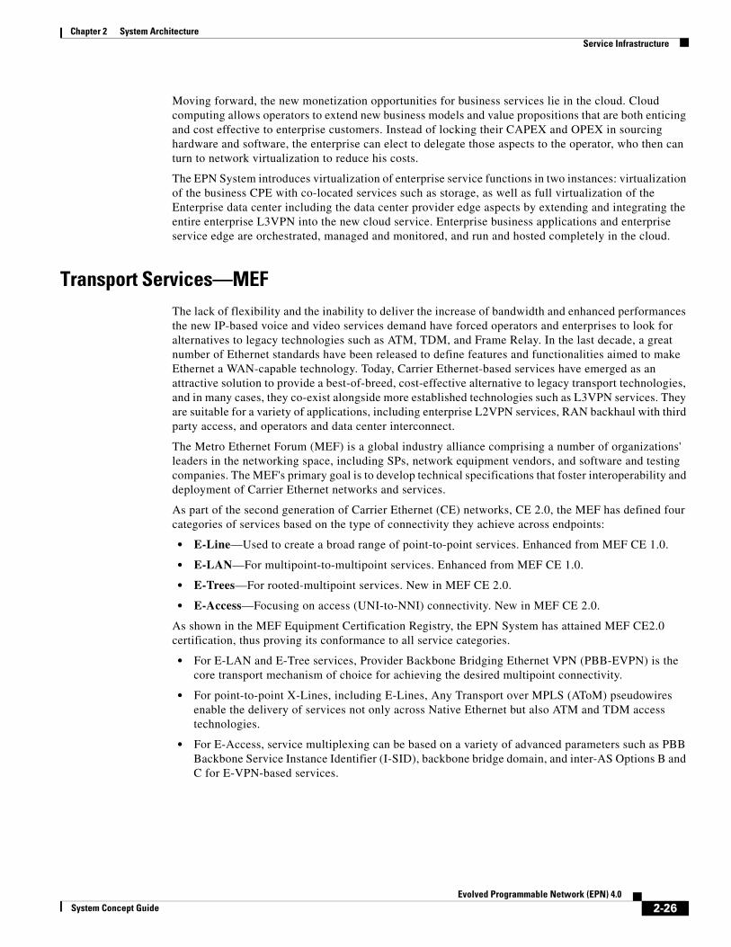
Chapter 2 System Architecture Service Infrastructure
Moving forward, the new monetization opportunities for business services lie in the cloud. Cloud computing allows operators to extend new business models and value propositions that are both enticing and cost effective to enterprise customers. Instead of locking their CAPEX and OPEX in sourcing hardware and software, the enterprise can elect to delegate those aspects to the operator, who then can turn to network virtualization to reduce his costs.
The EPN System introduces virtualization of enterprise service functions in two instances: virtualization of the business CPE with co-located services such as storage, as well as full virtualization of the Enterprise data center including the data center provider edge aspects by extending and integrating the entire enterprise L3VPN into the new cloud service. Enterprise business applications and enterprise service edge are orchestrated, managed and monitored, and run and hosted completely in the cloud.
Transport Services—MEFThe lack of flexibility and the inability to deliver the increase of bandwidth and enhanced performances the new IP-based voice and video services demand have forced operators and enterprises to look for alternatives to legacy technologies such as ATM, TDM, and Frame Relay. In the last decade, a great number of Ethernet standards have been released to define features and functionalities aimed to make Ethernet a WAN-capable technology. Today, Carrier Ethernet-based services have emerged as an attractive solution to provide a best-of-breed, cost-effective alternative to legacy transport technologies, and in many cases, they co-exist alongside more established technologies such as L3VPN services. They are suitable for a variety of applications, including enterprise L2VPN services, RAN backhaul with third party access, and operators and data center interconnect.
The Metro Ethernet Forum (MEF) is a global industry alliance comprising a number of organizations' leaders in the networking space, including SPs, network equipment vendors, and software and testing companies. The MEF's primary goal is to develop technical specifications that foster interoperability and deployment of Carrier Ethernet networks and services.
As part of the second generation of Carrier Ethernet (CE) networks, CE 2.0, the MEF has defined four categories of services based on the type of connectivity they achieve across endpoints:
• E-Line—Used to create a broad range of point-to-point services. Enhanced from MEF CE 1.0.
• E-LAN—For multipoint-to-multipoint services. Enhanced from MEF CE 1.0.
• E-Trees—For rooted-multipoint services. New in MEF CE 2.0.
• E-Access—Focusing on access (UNI-to-NNI) connectivity. New in MEF CE 2.0.
As shown in the MEF Equipment Certification Registry, the EPN System has attained MEF CE2.0 certification, thus proving its conformance to all service categories.
• For E-LAN and E-Tree services, Provider Backbone Bridging Ethernet VPN (PBB-EVPN) is the core transport mechanism of choice for achieving the desired multipoint connectivity.
• For point-to-point X-Lines, including E-Lines, Any Transport over MPLS (AToM) pseudowires enable the delivery of services not only across Native Ethernet but also ATM and TDM access technologies.
• For E-Access, service multiplexing can be based on a variety of advanced parameters such as PBB Backbone Service Instance Identifier (I-SID), backbone bridge domain, and inter-AS Options B and C for E-VPN-based services.
2-26Evolved Programmable Network (EPN) 4.0
System Concept Guide
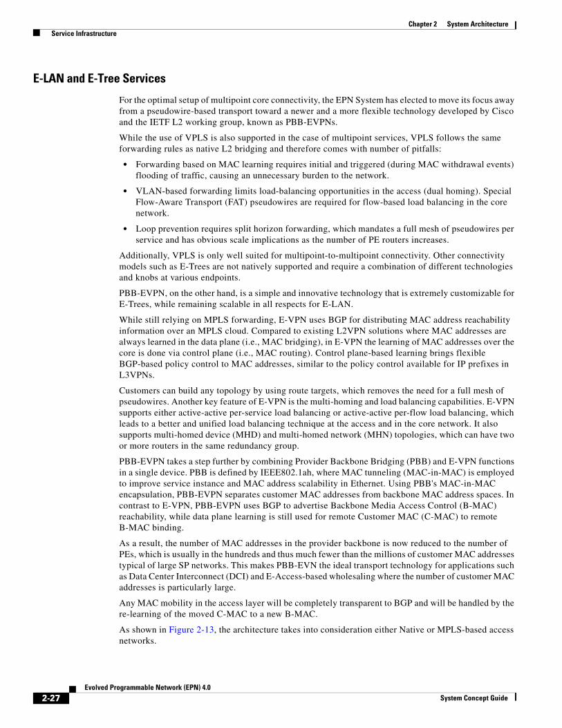
Chapter 2 System Architecture Service Infrastructure
E-LAN and E-Tree Services
For the optimal setup of multipoint core connectivity, the EPN System has elected to move its focus away from a pseudowire-based transport toward a newer and a more flexible technology developed by Cisco and the IETF L2 working group, known as PBB-EVPNs.
While the use of VPLS is also supported in the case of multipoint services, VPLS follows the same forwarding rules as native L2 bridging and therefore comes with number of pitfalls:
• Forwarding based on MAC learning requires initial and triggered (during MAC withdrawal events) flooding of traffic, causing an unnecessary burden to the network.
• VLAN-based forwarding limits load-balancing opportunities in the access (dual homing). Special Flow-Aware Transport (FAT) pseudowires are required for flow-based load balancing in the core network.
• Loop prevention requires split horizon forwarding, which mandates a full mesh of pseudowires per service and has obvious scale implications as the number of PE routers increases.
Additionally, VPLS is only well suited for multipoint-to-multipoint connectivity. Other connectivity models such as E-Trees are not natively supported and require a combination of different technologies and knobs at various endpoints.
PBB-EVPN, on the other hand, is a simple and innovative technology that is extremely customizable for E-Trees, while remaining scalable in all respects for E-LAN.
While still relying on MPLS forwarding, E-VPN uses BGP for distributing MAC address reachability information over an MPLS cloud. Compared to existing L2VPN solutions where MAC addresses are always learned in the data plane (i.e., MAC bridging), in E-VPN the learning of MAC addresses over the core is done via control plane (i.e., MAC routing). Control plane-based learning brings flexible BGP-based policy control to MAC addresses, similar to the policy control available for IP prefixes in L3VPNs.
Customers can build any topology by using route targets, which removes the need for a full mesh of pseudowires. Another key feature of E-VPN is the multi-homing and load balancing capabilities. E-VPN supports either active-active per-service load balancing or active-active per-flow load balancing, which leads to a better and unified load balancing technique at the access and in the core network. It also supports multi-homed device (MHD) and multi-homed network (MHN) topologies, which can have two or more routers in the same redundancy group.
PBB-EVPN takes a step further by combining Provider Backbone Bridging (PBB) and E-VPN functions in a single device. PBB is defined by IEEE802.1ah, where MAC tunneling (MAC-in-MAC) is employed to improve service instance and MAC address scalability in Ethernet. Using PBB's MAC-in-MAC encapsulation, PBB-EVPN separates customer MAC addresses from backbone MAC address spaces. In contrast to E-VPN, PBB-EVPN uses BGP to advertise Backbone Media Access Control (B-MAC) reachability, while data plane learning is still used for remote Customer MAC (C-MAC) to remote B-MAC binding.
As a result, the number of MAC addresses in the provider backbone is now reduced to the number of PEs, which is usually in the hundreds and thus much fewer than the millions of customer MAC addresses typical of large SP networks. This makes PBB-EVN the ideal transport technology for applications such as Data Center Interconnect (DCI) and E-Access-based wholesaling where the number of customer MAC addresses is particularly large.
Any MAC mobility in the access layer will be completely transparent to BGP and will be handled by the re-learning of the moved C-MAC to a new B-MAC.
As shown in Figure 2-13, the architecture takes into consideration either Native or MPLS-based access networks.
2-27Evolved Programmable Network (EPN) 4.0
System Concept Guide

Chapter 2 System Architecture Service Infrastructure
Figure 2-13 MEF Transport Services Architecture—E-LAN and E-Tree
In the case of Native Ethernet access, the EPN System incorporates hub-and-spoke topologies and dual homing using MC-LAG and G.8032-protected ring topologies, with Fiber to the Business and PON access technologies.
As operators grow more and more concerned about the operational costs and challenges of managing the increasing number of access devices enabled by the bandwidth availability and cost effectiveness of these new Ethernet-based access networks, the system also introduces the network Virtualization (nV).
nV enables the service edge node to become the single touch point for the control and the configuration of all the remote access nodes without any alteration in the connectivity across devices in the access domain.
In both Native and MPLS access, BGP E-VPN address-family can be hosted on the pre-aggregation/aggregation nodes, so as to minimize the number of BGP neighbors and to avoid any potential MAC address scaling issues on the access nodes. In the case of MPLS Access, transport of the L2VPN from the access node to the actual service edge is accomplished via Ethernet PWE3. The access pseudowire is then attached to the Ethernet VPN Instance (EVI) at the service edge node for connectivity into the PBB-EVPN cloud.
E-Line Services
For E-Line services, like Ethernet Private Lines (EPL) and Ethernet Virtual Private Lines (EVPL), the EPN System relies on the full transparency, scale and flexible positioning of the service endpoint of EoMPLS. EoMPLS pseudowires are used to achieve end-to-end connectivity between any two service end points.
In addition, the system supports transport of legacy access technologies such as ATM and TDM, both structured (SAToP) and unstructured (CESoPSN), over more generic AToM pseudowires.
As shown in Figure 2-14, the system again takes into consideration either Native or MPLS-based access networks.
PB-EVPN
PB-EVPN
2948
50
Pre-Aggregation NodeASR-9001, ASR-903
Aggregation NodeASR-9001, 9006
Aggregation NodeASR-9010
DWDM, Mesh TopologyDWDM, Fiber Rings, H&S, Hierarchical TopologyxWDM, Fiber Rings
MultiserviceCore Network
LegacyAccess Network
Large ScaleAggregation Network
Core Node
IP/MPLS Transport IP/MPLS Transport
Ethernet Port, 802.1q
E-LAN Ethernet PWE3
Ethernet PWE3
Ethernet Port, 802.1q or 802.1ad
E-LAN
AGN-SE
Optimal Service Edge,PAN-SE, AGN-SE
Access NodeME-3600X, ASR-901, 9000v
nV, P2P, Chain,Ring, L2 Fabric
Ethernet P2P,G8032 Ring
PAN-SE
2-28Evolved Programmable Network (EPN) 4.0
System Concept Guide
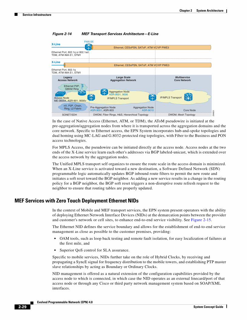
Chapter 2 System Architecture Service Infrastructure
Figure 2-14 MEF Transport Services Architecture—E-Line
In the case of Native Access (Ethernet, ATM, or TDM), the AToM pseudowire is initiated at the pre-aggregation/aggregation nodes from where it is transported across the aggregation domains and the core network. Specific to Ethernet access, the EPN System incorporates hub-and-spoke topologies and dual homing using MC-LAG and G.8032-protected ring topologies, with Fiber to the Business and PON access technologies.
For MPLS Access, the pseudowire can be initiated directly at the access node. Access nodes at the two ends of the X-Line service learn each other's addresses via BGP labeled-unicast, which is extended over the access network by the aggregation nodes.
The Unified MPLS transport self organizes to ensure the route scale in the access domain is minimized. When an X-Line service is activated toward a new destination, a Software Defined Network (SDN) programmable logic automatically updates BGP inbound route filters to permit the new route and initiates a soft reset toward the BGP neighbor. As adding a new service results in a change in the routing policy for a BGP neighbor, the BGP soft reset triggers a non-disruptive route refresh request to the neighbor to ensure that routing tables are properly updated.
MEF Services with Zero Touch Deployment Ethernet NIDs
In the context of Mobile and MEF transport services, the EPN system present operators with the ability of deploying Ethernet Network Interface Devices (NIDs) at the demarcation points between the provider and customer's network or cell sites, to enhance end-to-end service visibility. See Figure 2-15.
The Ethernet NID defines the service boundary and allows for the establishment of end-to-end service management as close as possible to the customer premises, providing:
• OAM tools, such as loop back testing and remote fault isolation, for easy localization of failures at the first mile, and
• Superior QoS control for SLA assurance.
Specific to mobile services, NIDs further take on the role of Hybrid Clocks, by receiving and propagating a SyncE signal for frequency distribution to the mobile towers, and establishing PTP master slave relationships by acting as Boundary or Ordinary Clocks.
NID management is offered as a natural extension of the configuration capabilities provided by the access node to which is connected, in which case the NID operates as an external linecard/port of that access node or through any Cisco or third party network management system based on SOAP/XML interfaces.
2948
51
Pre-Aggregation NodeASR-9001, ASR-903
Aggregation NodeASR-9001, 9006
Aggregation NodeASR-9010
DWDM, Mesh TopologyDWDM, Fiber Rings, H&S, Hierarchical TopologySONET/SDH
MultiserviceCore Network
LegacyAccess Network
Large ScaleAggregation Network
Core Node
IP/MPLS Transport IP/MPLS Transport
Ethernet Port, 802.1qTDM, ATM IMA E1, STM1
X-Line Ethernet, CESoPSN, SAToP, ATM VC/VP PWE3
X-Line
Ethernet Port, 802.1q or 802.1adTDM, ATM IMA E1, STM1
PAN-SE
Ethernet, CESoPSN, SAToP, ATM VC/VP PWE3
Access NodeME-3600X, ASR-901, 9000v
nV, P2P, Chain,Ring, L2 Fabric
Ethernet P2P,G8032 Ring
2-29Evolved Programmable Network (EPN) 4.0
System Concept Guide
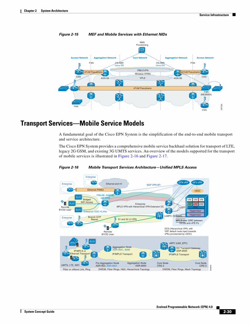
Chapter 2 System Architecture Service Infrastructure
Figure 2-15 MEF and Mobile Services with Ethernet NIDs
Transport Services—Mobile Service ModelsA fundamental goal of the Cisco EPN System is the simplification of the end-to-end mobile transport and service architecture.
The Cisco EPN System provides a comprehensive mobile service backhaul solution for transport of LTE, legacy 2G GSM, and existing 3G UMTS services. An overview of the models supported for the transport of mobile services is illustrated in Figure 2-16 and Figure 2-17.
Figure 2-16 Mobile Transport Services Architecture—Unified MPLS Access
2973
05
CSG
FAN
FAN(ME3600X)
PAN CN-ABRInline RR
CN-ABRInline RR
PAN
Core NetworkAccess Network Aggregation Network Aggregation Network Access Network
AToM Pseudowire
PBB-EVPN
Wireless VPWS
VPLSAGN-SE AGN-SECSG CSG
AToM Pseudowire AToM Pseudowire
NMSProvisioning
Hypervisor
Hypervisor
VRFVPE
VRF VRF
VMVM VM
2948
49
Pre-Aggregation NodeASR-903, ASR-9001
DWDM, Fiber Rings, Mesh TopologyDWDM, Fiber Rings, H&S, Hierarchical TopologyFiber or uWave Link, Ring
Core NodeCRS-3
Core NodeCRS-3
IP/MPLS Transport
UMTS, LTE, WiFi
IP/MPLS Transport
RemoteBYOD User
(v)MPC (S/PGW)
MPLS over GRE betweenDCGs and vPE-Fs
Aggregation NodeASR-9000
BGP VPN AFI
IP/MPLS orEthernet Transport
Ethernet and nV
vSOC
VV
VVV
Enterprise
Enterprise SSID VLANs
Enterprise
EnterpriseMPLS VPN with Hierarchical VPN Extension DC
S1 and X2 L3 VPN
BridgedWiFi Access
Enterprise
EnterpriseEnterprise
Aggregation NodeASR-9001, 9006
DC Transport GatewayASR-9000
vMPC (LMA_EPC)
DCG (Hierarchical VPN, withVRF default route inject towardsvPEs provisioned by vSOC)
RemoteBYOD User
Ethernet PWE3
PAN-SE, AGN-SEwith WAG
EPN vRR NFV vRR
Branch GTPBearer
2-30Evolved Programmable Network (EPN) 4.0
System Concept Guide
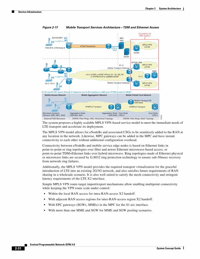
Chapter 2 System Architecture Service Infrastructure
Figure 2-17 Mobile Transport Services Architecture—TDM and Ethernet Access
The system proposes a highly scalable MPLS VPN-based service model to meet the immediate needs of LTE transport and accelerate its deployment.
The MPLS VPN model allows for eNodeBs and associated CSGs to be seamlessly added to the RAN at any location in the network. Likewise, MPC gateways can be added in the MPC and have instant connectivity to each other without additional configuration overhead.
Connectivity between eNodeBs and mobile service edge nodes is based on Ethernet links in point-to-point or ring topologies over fiber and newer Ethernet microwave-based access, or point-to-point TDM+Ethernet links over hybrid microwave. Ring topologies made of Ethernet physical or microwave links are secured by G.8032 ring protection technology to ensure sub-50msec recovery from network ring failures.
Additionally, the MPLS VPN model provides the required transport virtualization for the graceful introduction of LTE into an existing 2G/3G network, and also satisfies future requirements of RAN sharing in a wholesale scenario. It is also well suited to satisfy the mesh connectivity and stringent latency requirements of the LTE X2 interface.
Simple MPLS VPN route-target import/export mechanisms allow enabling multipoint connectivity while keeping the VPN route scale under control:
• Within the local RAN access for intra-RAN-access X2 handoff.
• With adjacent RAN access regions for inter-RAN-access region X2 handoff.
• With EPC gateways (SGWs, MMEs) in the MPC for the S1-u/c interface.
• With more than one MME and SGW for MME and SGW pooling scenarios.
MPLS VPN(v4/v6)
RNCBBC
2948
53ASR-903, 9001 ASR-9000
DWDM, Fiber Rings, Mesh TopologyDWDM, Fiber Rings, H&S, Hierarchical TopologyEthernet/TDM Microwave
Mobile Packet Core NetworkMobile Access Network Mobile Aggregation Network
CRS-3CRS-3
IP/MPLS Transport
Partners: NSN, NEC, SIAE
MPLS VPN(v4/v6)
MPLS VPN(v4/v6)
Aggregation Node Aggregation Node Core NodeCore NodeMicrowave Systems
IP/MPLS Transport
Mobile Transport PEASR-9000
TDM BTS, ATM Node B
SDH/SONET
ATM orTDM
SGSN
GGSN
AToM Pseudowire
v4 or v6 MPL+mGRE VPN for S1, X2, M3, M1or IP/PIMv4/v6 for eMBMS M3/M1
X2-C, X2-U
S/PGW LMA
Covered by theMPC System
S1-C
S1-U
MME
Mobile Transport Gateway
Mobile Transport Gateway
S1/X2 and M1/M3 require different IP endpoints and VLAN interfaces in eNB when IP/PIM is used for M3/M1
2-31Evolved Programmable Network (EPN) 4.0
System Concept Guide

Chapter 2 System Architecture Service Infrastructure
Figure 2-18 Mobile Transport Service Routes Filtering Architecture
As shown in Figure 2-18, the system defines the following route targets to satisfy all possible connectivity requirements while achieving optimal traffic patterns:
• A unique route target (RT) denoted as Common RT is assigned to the LTE backhaul MPLS VPN. It is exported by all CSGs across all access domains and it is imported by the MTG in the MPC. Provides reachability from the MPC to all eNodeBs in the network.
• A unique RT denoted by MPC RT is assigned to the MTG in the MPC. It is imported by all CSGs across all access domains. Provides reachability from the eNodeBs to the MPC.
• Each aggregation or each RAN access region in the in the network, depending on the route scale supported by the CSG in each region, is assigned a unique RT denoted as AGGR or RAN RT, respectively. Each CSG in a given access domain exports the local AGGR or RAN RT and imports the AGGR or RAN RT of neighboring aggregations or access domains. Provides direct inter-RAN communication for X2 interfaces across eNodeBs.
The rapid adoption of LTE and the massive increase in subscriber growth is leading to an exponential increase in cell sites that are being deployed in the network. This is introducing a crunch in the number of IP addresses that need to be assigned to the eNodeBs at the cell sites. For mobile operators that are running out of public IPv4 addresses or those who cannot obtain additional public IPv4 addresses from the registries, the Cisco EPN System enables carrying IPv6 traffic over an IPv4 Unified MPLS Transport infrastructure using 6VPE as defined in RFC 4659. The eNodeBs and packet gateways can be IPv6 only or dual-stack enabled to support IPv6 for S1 and X2 interfaces while using IPv4 for network management functions, if desired. The dual-stack eNodeBs and packet gateways connect to CSGs and MTGs configured with a dual stack VRF carrying VPNv4 and VPNv6 routes. IPv6 reachability between the eNodeBs and the packet gateways is exchanged between the CSGs and transport gateways using the BGP MPLS VPN IPv6 address family.
In respect to transport services for mobile multicast traffic, the 3rd Generation Partnership Project (3GPP) has recently added eMBMS to the LTE releases, a mechanism to efficiently deliver common content, such as broadcast video or file push, to a large number of different end users. Content delivered via eMBMS services uses a multicast-based transport mechanism, minimizing packet duplication within the transport network.
As mobile operators have started to implement eMBMS services, the EPN System has extended its architecture to accommodate the new interfaces being defined. In this regard, the system is specifically involved in the transport of two new interfaces:
297306
MTG
MTG
MTG
SGW/PGW
SGW/PGW
Core NetworkAggregation Network
LTE TransportMPLS VPNv4/v6
Aggregation Network
Export: MPC RTImport: MPC RT, Common RT
MME
VRF
VRF VRF
VRF VRF
VRF VRF
VRF VRF
VRF VRFVRF VRF
VRFVRF
Export: RAN Z RT, Common RTImport: RAN Z RT, MPC RT
Export: RAN Y RT, Common RTImport: RAN Y RT, MPC RT
Export: RAN W RT,Common RT
Import: RAN W RT,MPC RT
VRF
2-32Evolved Programmable Network (EPN) 4.0
System Concept Guide

Chapter 2 System Architecture Service Infrastructure
• M3 Interface—A unicast interface between the MME and the eNB, which primarily carries Multimedia Broadcast Multicast Service (MBMS) session management signaling.
• M1 Interface—A downstream user-plane interface between the MBMS Gateway (MBMS-GW) and the eNB, which delivers content to the user endpoint. IP Multicast is used to transport the M1 interface traffic.
Within the architecture, the M3 interface is modeled as an extension of the S1 interface, which has the same connectivity requirements, and therefore is assimilated into the same L3 MPLS VPN used for mobile unicast services. The M1 interface, instead, which in the mobile space has unique connectivity patterns, is handled independently via IP Multicast.
The multicast mechanism utilized for transporting the M1 interface traffic depends upon the network location. In the core and aggregation domains, transport happens via LSM and mLDP-Global in-band signaling profile, which provide efficient and resilient transport of the multicast traffic within these regions as well as a flexible transport for consumer video applications that can be easily unified to support either mobile or wireline users. In the access domain, native IP Multicast is preferred to provide efficient and resilient transport while utilizing the lowest amount of resources on smaller nodes. At the CSGs IP multicast traffic can be optionally leaked back into the same L3VPN used for S1, M3 and X2 traffic, thus allowing the provisioning of a single uplink interface, or VLAN, between the eNodeB and its CSG node.
Service virtualization with MPLS-based L2 and L3 VPNs also allows legacy 2G GSM and existing 3G UMTS services to co-exist with LTE on the same transport infrastructure. The system supports mobile service providers (MSP) with GSM and ATM-based UMTS deployments wishing to remove, reduce, or cap investments in SONET/SDH and ATM transport infrastructure by using MPLS-based CEoP services.
• For the MSPs who want to reduce SONET/SDH infrastructure used for GSM, Cisco EPN enables PWE3-based transport of emulated TDM circuits. Structured circuit emulation is achieved with CESoPSN, and unstructured emulation is achieved with SAToP. E1/T1 circuits from BTS equipment connected to the CSG or to the PAN are transported to MTG, where they are bundled into channelized STM1/OC-3 interfaces for handoff to the BSC.
• For the MSPs who want to reduce their ATM infrastructure used for ATM-based UMTS, Cisco EPN enables ATM VC (AAL0 or AAL5) or VP (AAL0) PWE3-based transport. ATM E1/T1 or IMA interfaces from NodeB equipment connected to the CSG or PAN can be transported to the MTG, where they are bundled into STM1 ATM interfaces for handoff to the RNC. Cell packing may be used to optimize the bandwidth used for this transport.
For all the above service models, the system supports physical layer synchronization of frequency based on SyncE, or packet-based synchronization of frequency as well as phase.
Mobile Transport Capacity Monitoring
The rapid evolution of smart mobile devices, loaded with applications for anytime, anywhere data consumption, is a major triggering factor for the deployment of data analytics tools that allow mobile operators to gain visibility over usage trends within a given cell site and at the radio interface level to proactively refine operations and network sizing based on actual resource consumption. See Figure 2-19.
2-33Evolved Programmable Network (EPN) 4.0
System Concept Guide

Chapter 2 System Architecture Service Infrastructure
Figure 2-19 Mobile Transport Capacity Monitoring
NetFlow exporter capabilities enabled at the MTG nodes monitor mobile packets and export flow records to a NetFlow Collector function implemented by Cisco Prime Performance Monitoring.
Monitoring of mobile packets applies to either legacy or new IP-based model technologies. Specific to 2G and ATM based 3G technologies, the NetFlow exporter monitors the Abis or Iub interface at the ATOM PW level, while for LTE and Wi-Fi, the flow collection particular to the S1 interface is based on the L3VPN associated to the mobile service.
Service Control PlaneTo optimize the network infrastructure costs, the EPN System proposes the integration of BGP Service Route Reflectors (RR), Policy and Charging Rule Function (PCRF), and Network Management System (NMS) as virtualized functions running over a common pool of standard server systems in the operator's data center.
In regards to RR functions, similar to what discussed for the Transport BGP Control Plane, the Cisco EPN System proposes a vRR design also for the setup of the Service BGP control plane.
Figure 2-20 depicts the service BGP control plane aspects for the most comprehensive network design based on multi-domain IGPs and Inter-AS organizations.
2973
07
CSG withLTE eNB
MTG,RNC
MTG,SGW
MTG,SGW
AGN-SE
AToM PWE3 AToM PWE3
AGN-SE
CSG withLegacy BTS
CSG
CSG withLTE eNB
CSG withLegacy BTS
CSG
MPLS VPN forLTE eNBs
NetflowCollection and Analysis
MTG, MME
2-34Evolved Programmable Network (EPN) 4.0
System Concept Guide
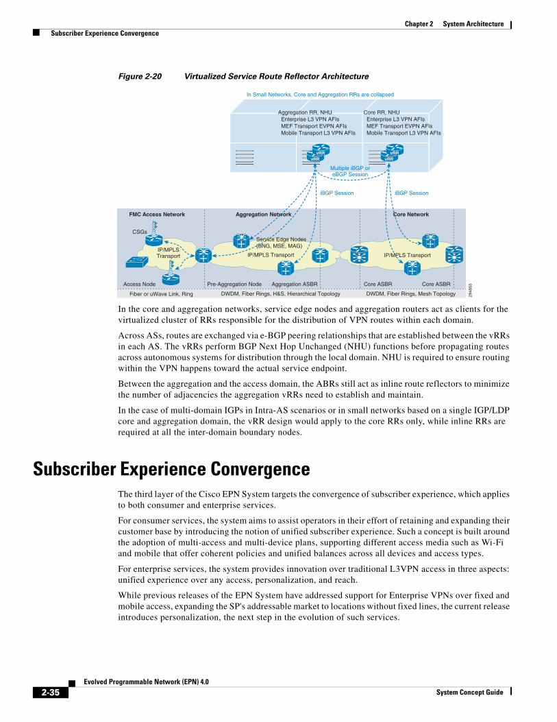
Chapter 2 System Architecture Subscriber Experience Convergence
Figure 2-20 Virtualized Service Route Reflector Architecture
In the core and aggregation networks, service edge nodes and aggregation routers act as clients for the virtualized cluster of RRs responsible for the distribution of VPN routes within each domain.
Across ASs, routes are exchanged via e-BGP peering relationships that are established between the vRRs in each AS. The vRRs perform BGP Next Hop Unchanged (NHU) functions before propagating routes across autonomous systems for distribution through the local domain. NHU is required to ensure routing within the VPN happens toward the actual service endpoint.
Between the aggregation and the access domain, the ABRs still act as inline route reflectors to minimize the number of adjacencies the aggregation vRRs need to establish and maintain.
In the case of multi-domain IGPs in Intra-AS scenarios or in small networks based on a single IGP/LDP core and aggregation domain, the vRR design would apply to the core RRs only, while inline RRs are required at all the inter-domain boundary nodes.
Subscriber Experience ConvergenceThe third layer of the Cisco EPN System targets the convergence of subscriber experience, which applies to both consumer and enterprise services.
For consumer services, the system aims to assist operators in their effort of retaining and expanding their customer base by introducing the notion of unified subscriber experience. Such a concept is built around the adoption of multi-access and multi-device plans, supporting different access media such as Wi-Fi and mobile that offer coherent policies and unified balances across all devices and access types.
For enterprise services, the system provides innovation over traditional L3VPN access in three aspects: unified experience over any access, personalization, and reach.
While previous releases of the EPN System have addressed support for Enterprise VPNs over fixed and mobile access, expanding the SP's addressable market to locations without fixed lines, the current release introduces personalization, the next step in the evolution of such services.
2948
55Pre-Aggregation Node Aggregation ASBR
DWDM, Fiber Rings, Mesh TopologyDWDM, Fiber Rings, H&S, Hierarchical TopologyFiber or uWave Link, Ring
Core NetworkFMC Access Network Aggregation Network
Core ASBRCore ASBR
IP/MPLS Transport
Access Node
CSGs
IP/MPLS Transport
Service Edge Nodes(BNG, MSE, MAG)
iBGP Session
Multiple iBGP oreBGP Session
iBGP Session
IP/MPLSTransport
vRRvRR
vRRvRR
Aggregation RR, NHU Enterprise L3 VPN AFIs MEF Transport EVPN AFIs Mobile Transport L3 VPN AFIs
Core RR, NHU Enterprise L3 VPN AFIs MEF Transport EVPN AFIs Mobile Transport L3 VPN AFIs
In Small Networks, Core and Aggregation RRs are collapsed
2-35Evolved Programmable Network (EPN) 4.0
System Concept Guide

Chapter 2 System Architecture Subscriber Experience Convergence
Enterprise L3VPN services have historically been pretty stationary--set up once by the operator based on pre-defined agreements that specify the level of service required, and never touched again unless a new SLA was explicitly stipulated. EPN System proposes new business models for operators, by introducing the concept of Personalized L3VPNs. Under these new models, the customer is presented with a selection of on-demand services in different tiers (or SLAs) and billing is rated based on time or traffic volume that a customer site spent or generated within a given service tier. Operational costs are reduced thanks to the automated provisioning logic, while customer retention and adoption are improved through service offerings that dynamically evolve with the enterprise needs.
Additionally, enterprise boundaries have blurred over the past years. Companies are embracing the BYOD experience to allow employees access to enterprise resources not only from personal devices, but also from any location. To cater to those needs, the EPN System defines an architecture for remote BYOD access, based on Wi-Fi and mobile technologies that create new revenue opportunities for operators by allowing them to extend traditional enterprise L3VPNs services to this new category of off-site enterprise users. Moreover, the experience of the BYOD user is personalized by enterprise policies that apply cohesively irrespective of access into the enterprise network happening from an on-site location or on the go.
The following sections discuss these new models in more detail.
Unified Subscriber ExperienceThe Unified Subscriber Experience concept, as shown in Figure 2-21, is built around the adoption of multi-access and multi-device plans that allow end-users to attain simultaneous access in the operator network from a number of different devices, locations, and access types, including traditional fixed wireline, and wireless methods, such as Wi-Fi and mobile.
Figure 2-21 Unified Subscriber Experience Architecture
A converged PCRF function applies subscriber policies across the various Policy Enforcement Points consistently to the service tier purchased and according to the rules and mechanisms specific to the given access type, which include a combination of RADIUS and diameter interfaces.
Multiple devices in the same subscriber's account share a common balance. Subscriber access through the various media is rated differently; subscribers are steered toward cheaper access types (wireline > Wi-Fi > mobile) through more advantageous monetary conditions and metering rules.
Specifically, the system addresses the following use cases:
• Transparent Authorization—Enables users to be automatically signed into the network without need for redirection to a portal for web-based authentication. It applies to wireline, mobile, and Wi-Fi access.
2948
56
Fixed Edge(BNG)
RADIUS COA
RADIUS COA
Converged PCRF
Gx, Gy
Mobile Edge(PGW, GGSN)
WiFi Edge(LMA)
HSS HLR AAA
2-36Evolved Programmable Network (EPN) 4.0
System Concept Guide

Chapter 2 System Architecture Subscriber Experience Convergence
• Web Logon for Wi-Fi Access with Dynamic Learning of Credentials—Allows dynamic learning of network credentials of unregistered Wi-Fi devices by redirecting the user to a web logon portal the first time he accesses the operator's network from an unknown appliance. The device MAC address is then automatically registered in the subscriber's account and used for transparent authorization of subsequent accesses from the same device. It applies to Wi-Fi access only. It assumes credentials for other access types are pre-provisioned in the subscriber's account.
• Weighted Fair Usage—Provides capped access based on a shared balance per subscriber account. Steers subscribers toward cheaper access types (wireline > Wi-Fi > mobile) through more advantageous monetary conditions and metering rules.
• Tiered Weighted Fair Usage—Generates additional revenue by capturing a larger portion of the market through differentiated offerings that cater to specific usage needs. This encourages customer adoption of higher tier plans by setting different limits to the number of simultaneous active devices in the network.
Personalized Enterprise L3VPNs with Fixed And Mobile AccessPersonalized Enterprise L3VPN, as illustrated in Figure 2-22, adds programmable and billable SLAs capabilities to the provisioning of traditional provider edge interfaces.
Through offerings that dynamically adapt to the enterprise immediate needs and behaviors, operators can better meet the specific demands of a customer or customer location. As an example, access policies and associated billing models can be modified instantaneously to allow for an increase in bandwidth due to a large database migration or backup across locations, or additional employee presence at a given site.
Figure 2-22 Personalized Enterprise L3VPNs Architecture
The system builds upon the capabilities of established NMSs, acting as the central place where all applicable customer policies and business rules are defined and newer PCRF servers, which perform all the policy management functions, including selection and activation on service edge nodes.
During authorization of the service edge node interface, the PCRF downloads the list of allowed policies from the NMS and provisions them on the network node according to the logic outlined by the associated business rule.
The EPN System defines two sets of business rules:
Enterprise
Enterprise
2948
57
CSG
FANCSG
Ethernet
LTE/3G IP BearerFSE
FAN
PCRF
Business L3 VPN (v4/v6) Services
S1 and X2 L3 VPN
AToM Pseudowire AToM Pseudowire
SQL ServiceCorrelation
NMS TraditionalProvisioning
RADIUS AAA forMobile Access QOS,
ACL, Accounting
RADIUS AAA forFixed Access QOS,
ACL, Accounting
FSE FSE
vMPC(PGW, GGSN)
2-37Evolved Programmable Network (EPN) 4.0
System Concept Guide

Chapter 2 System Architecture Subscriber Experience Convergence
• In the Weekly Schedule scenario, the PCRF receives policies for both business and off-business hours and applies them according to the local time. The process is ongoing, with policies being automatically updated based on recurring time-based events.
• In the Bandwidth on Demand scenario, the PCRF receives a list of tiered policies and provisions the default one when the service is first set up at the network node. It then exposes the full list to the enterprise customer via a Web Portal interface for on-demand upgrades and downgrades.
The solution applies to both mobile and fixed access, thus expanding the addressable market to locations with and without wireline access. Mobile and fixed service edge nodes are then responsible to provide the proper SLAs through a combination of QoS, Security, and Accounting features.
Additionally, in perfect alignment with the optimal placement of the service edge functions, the solution is fully supported with both Ethernet and MPLS based fixed access, making it applicable to all the deployment models the EPN enterprise service infrastructure supports.
Seamless Remote Access to Enterprise L3VPNSeamless Remote Access, as illustrated in Figure 2-23, personalizes the enterprise L3VPN services at the employee level by enabling remote access for off-site BYOD users.
The solution provides an alternative to client-based VPNs in the effort to deliver an enhanced experience to off-site employees.
Figure 2-23 Seamless Remote Access to Enterprise Architecture
Client-based VPN traffic travels over Internet connections as over-the-top traffic, and therefore is only offered best effort treatment. By connecting the user to the enterprise directly at the operator's premises, SLA and access policies can be applied as early as at the operator service edge node, thus modeling the BYOD access as a traditional Enterprise L3VPN.
BYOD access is authorized directly by the enterprise Identity Service Engines (ISEs) after being proxied at the operator PCRF. Security and QoS policies are delegated by the enterprise and are applied at the operator's service edge nodes.
Both Wi-Fi and Mobile access are supported:
• For Wi-Fi access, operator's access points advertise Enterprise SSIDs that are protected by WPA/WPA2 security protocols. A two-step authentication process is employed to grant or deny BYOD association at the access point first, and to authorize enterprise-defined network policies and VPN assignment at the fixed service edge next.
2948
58
MSE(WAG in FSE)
AssociationEAP over RADIUS
PCRF
ISE
BYODSession AAA
RADIUS
BYODSession AAA
Diameter
MSE (EPC,GGSN in vMPC)
Business MobileDevices (BYOD)
Business MobileDevices (BYOD)
FMCAccess Network
Enterprise L3 VPN
Fixed Home,Enterprise SSID
IPIP
FMCAccess Network
Public WiFiEnterprise SSID
AuthorizationDelegation, SLA
Enforcement
2-38Evolved Programmable Network (EPN) 4.0
System Concept Guide

Chapter 2 System Architecture Subscriber Experience Convergence
• For Mobile access, BYOD users directly connect to an Access Point Name (APN) that provides access to their enterprise network. Once the subscriber is authenticated from within the APN, the EPC bearer is mapped to the enterprise VPN. The APN can be dedicated or shared among several enterprises, in which case additional parameters such as the domain portion of the username can be leveraged to determine the corresponding enterprise.
2-39Evolved Programmable Network (EPN) 4.0
System Concept Guide
System Concept Guide
C H A P T E R 3
Functional ComponentsUp to this point, we have addressed the transport infrastructure, service infrastructures, and subscriber experience convergence aspects of the Cisco EPN System architecture. This chapter, which looks at additional aspects required for delivering and operating a comprehensive EPN System architecture, includes the following major topics:
• Quality of Service (QoS), page 3-1
• Redundancy and High Availability, page 3-3
• OAM and Performance Monitoring, page 3-6
• Subscribers Identity Management, page 3-7
• Synchronization Distribution, page 3-8
Quality of Service (QoS)In order to enable SPs to offer Differentiated Services (DiffServ) and to guarantee SLAs, the EPN System provides sound capacity management techniques enabled by QoS functions implemented throughout the architecture.
A combination of flat and hierarchical QoS policies with a DiffServ-based classification allows the system to apply the adequate levels of prioritization at each stage in the network.
Within the aggregation and core networks, where strict control over individual subscriber's SLA is not required, flat QoS policies assign relative priority based on classes of traffic and agnostically to the service type.
Prioritization across services and within a given service is enforced at the subscriber and service UNI. The system enforces peak information rate (PIR) and committed information rate (CIR) for the different services through a combination of flat and hierarchical QoS (H-QoS) policies, applied at the access and service edge nodes. As an example, downstream H-QoS applied at the service edge nodes guarantees the most optimal usage of access bandwidth across and within a given service category. Flat or hierarchical QoS policies at the access nodes then secure relative priority among classes of traffic within a service or across services for dedicated or multiplexed UNI ports, respectively.
Figure 3-1 depicts the QoS models implemented for downstream traffic across the various services.
3-1Evolved Programmable Network (EPN) 4.0

Chapter 3 Functional Components Quality of Service (QoS)
Figure 3-1 Downstream QoS Model
For mobile access networks based on microwave connectivity, the system addresses the congestion issue resulting by the disparity in speed between air links and uplinks in microwave equipment. Nodes connecting to the microwave equipment implement H-QoS to throttle their transmission rate at the sustained microwave links speed, while ensuring differentiated treatment for the child classes.
Traffic classification follows the DiffServ architecture defined by the IETF and leverages mechanisms such as MPLS Experimental (EXP) bits, IP DSCP, IEEE 802.1p, and ATM CoS.
By using DiffServ-based classification, the system is capable of concurrently achieving prioritization between classes of traffic across all services, as well as within a service depending on the location in the network.
Figure 3-2 depicts the traffic classification, marking, and DiffServ PBH that the architecture adopts to fit the deployment of consumer, enterprise, and transport services.
2948
59
Pre-Aggregation NodeASR-9001, ASR-903
Aggregation NodeASR-9010
DWDM, Mesh TopologyDWDM, Fiber Rings, H&S, Hierarchical TopologyFiber, Microwave
MultiserviceCore Network
LegacyAccess Network
Large ScaleAggregation Network
Core Node
IP/MPLS TransportAccess NodeME-3600X, ASR-901, 9000v
Aggregation NodeASR-9001, 90006
IP/MPLS Transport
L3 Business,Subscriber UNI
L3 Business,Subscriber UNI
Mobile UNI
CNAGNRemote ANPAN-SEAGN-SE
Shaping/BW/BRR
Queuing andscheduling
Marking
Policing
Scheduling with Oversubscription,Priority PropagationBandwidth Remaining WRR
CO ANMobile NNI EthernetPort
MPLS NNI
MPLS NNI MPLS NNIBusiness,Subscriber UNI
Residential,Subscriber UNIs
Residential/WiFiInterface Session
BusinessL2 or L3 Sub Interface
Mobile NNI (L2 or L3)
L3 Business,PWHEInterface
vMPC
MPLS NNI
Shaped Rate ≤ Access Line + BRR
PIR/DIR perResidential Services SLA
Shaped Rate ≤ Access Line + BRR
Shaped Rate ≤ Access Line + BRR
Shaped Rate ≤ Access Line + BRR
nV, P2P, Chain,Ring, L2 Fabric
Ethernet P2P,G8032 Ring
3-2Evolved Programmable Network (EPN) 4.0
System Concept Guide
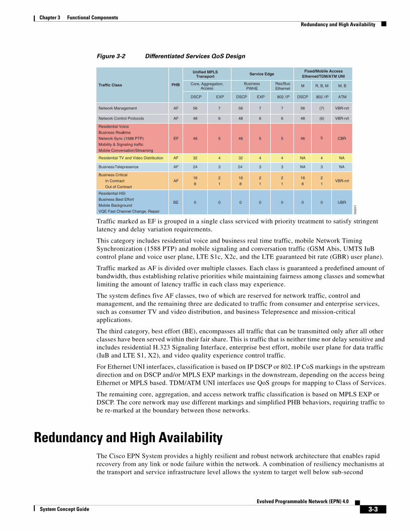
Chapter 3 Functional Components Redundancy and High Availability
Figure 3-2 Differentiated Services QoS Design
Traffic marked as EF is grouped in a single class serviced with priority treatment to satisfy stringent latency and delay variation requirements.
This category includes residential voice and business real time traffic, mobile Network Timing Synchronization (1588 PTP) and mobile signaling and conversation traffic (GSM Abis, UMTS IuB control plane and voice user plane, LTE S1c, X2c, and the LTE guaranteed bit rate (GBR) user plane).
Traffic marked as AF is divided over multiple classes. Each class is guaranteed a predefined amount of bandwidth, thus establishing relative priorities while maintaining fairness among classes and somewhat limiting the amount of latency traffic in each class may experience.
The system defines five AF classes, two of which are reserved for network traffic, control and management, and the remaining three are dedicated to traffic from consumer and enterprise services, such as consumer TV and video distribution, and business Telepresence and mission-critical applications.
The third category, best effort (BE), encompasses all traffic that can be transmitted only after all other classes have been served within their fair share. This is traffic that is neither time nor delay sensitive and includes residential H.323 Signaling Interface, enterprise best effort, mobile user plane for data traffic (IuB and LTE S1, X2), and video quality experience control traffic.
For Ethernet UNI interfaces, classification is based on IP DSCP or 802.1P CoS markings in the upstream direction and on DSCP and/or MPLS EXP markings in the downstream, depending on the access being Ethernet or MPLS based. TDM/ATM UNI interfaces use QoS groups for mapping to Class of Services.
The remaining core, aggregation, and access network traffic classification is based on MPLS EXP or DSCP. The core network may use different markings and simplified PHB behaviors, requiring traffic to be re-marked at the boundary between those networks.
Redundancy and High AvailabilityThe Cisco EPN System provides a highly resilient and robust network architecture that enables rapid recovery from any link or node failure within the network. A combination of resiliency mechanisms at the transport and service infrastructure level allows the system to target well below sub-second
2932
41
Traffic Class PHB
Unified MPLSTransport
Service EdgeFixed/Mobile Access
Ethernet/TDM/ATM UNI
Core, Aggregation,Access
BusinessPWHE
Res/BusEthernet
M R, B, M M, B
DSCP EXP DSCP EXP 802.1P DSCP 802.1P ATM
Network Management AF 56 7 56 7 7 56 (7) VBR-nrt
Network Control Protocols AF 48 6 48 6 6 48 (6) VBR-nrt
Residential Voice
Business Real-time
Network Sync (1588 PTP)
Mobility & Signaling traffic
Mobile Conversation/Streaming
EF 46 5 46 5 5 46 5 CBR
Residential TV and Video Distribution AF 32 4 32 4 4 NA 4 NA
Business Telepresence AF 24 3 24 3 3 NA 3 NA
Business Critical
In Contract
Out of Contract
AF16
8
2
1
16
8
2
1
2
1
16
8
2
1VBR-nrt
Residential HSI
Business Best Effort
Mobile Background
VQE Fast Channel Change, Repair
BE 0 0 0 0 0 0 0 UBR
3-3Evolved Programmable Network (EPN) 4.0
System Concept Guide
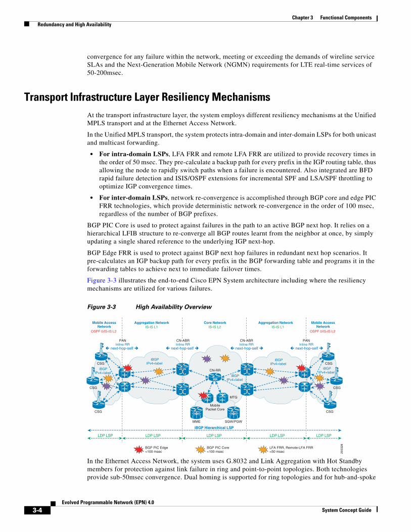
Chapter 3 Functional Components Redundancy and High Availability
convergence for any failure within the network, meeting or exceeding the demands of wireline service SLAs and the Next-Generation Mobile Network (NGMN) requirements for LTE real-time services of 50-200msec.
Transport Infrastructure Layer Resiliency MechanismsAt the transport infrastructure layer, the system employs different resiliency mechanisms at the Unified MPLS transport and at the Ethernet Access Network.
In the Unified MPLS transport, the system protects intra-domain and inter-domain LSPs for both unicast and multicast forwarding.
• For intra-domain LSPs, LFA FRR and remote LFA FRR are utilized to provide recovery times in the order of 50 msec. They pre-calculate a backup path for every prefix in the IGP routing table, thus allowing the node to rapidly switch paths when a failure is encountered. Also integrated are BFD rapid failure detection and ISIS/OSPF extensions for incremental SPF and LSA/SPF throttling to optimize IGP convergence times.
• For inter-domain LSPs, network re-convergence is accomplished through BGP core and edge PIC FRR technologies, which provide deterministic network re-convergence in the order of 100 msec, regardless of the number of BGP prefixes.
BGP PIC Core is used to protect against failures in the path to an active BGP next hop. It relies on a hierarchical LFIB structure to re-converge all BGP routes learnt from the neighbor at once, by simply updating a single shared reference to the underlying IGP next-hop.
BGP Edge FRR is used to protect against BGP next hop failures in redundant next hop scenarios. It pre-calculates an IGP backup path for every prefix in the BGP forwarding table and programs it in the forwarding tables to achieve next to immediate failover times.
Figure 3-3 illustrates the end-to-end Cisco EPN System architecture including where the resiliency mechanisms are utilized for various failures.
Figure 3-3 High Availability Overview
In the Ethernet Access Network, the system uses G.8032 and Link Aggregation with Hot Standby members for protection against link failure in ring and point-to-point topologies. Both technologies provide sub-50msec convergence. Dual homing is supported for ring topologies and for hub-and-spoke
2933
28
LDP LSP LDP LSP LDP LSPLDP LSP
iBGP Hierarchical LSP
LDP LSP
CSG CSG
CSG
MTG
MME SGW/PGW
MobilePacket Core
BGP PIC Edge<100 msec
CN-RR
CSG
iBGPIPv4+label
iBGPIPv4+label
iBGPIPv4+label
iBGPIPv4+label
iBGPIPv4+label
CSG CSG
Core NetworkIS-IS L2
Aggregation NetworkIS-IS L1
Aggregation NetworkIS-IS L1
Mobile AccessNetwork
OSPF 0/IS-IS L2
Mobile AccessNetwork
OSPF 0/IS-IS L2
RR
next-hop-self next-hop-self next-hop-self next-hop-self
PANInline RR
CN-ABRInline RR
PANInline RR
CN-ABRInline RR
BGP PIC Core<100 msec
LFA FRR, Remote-LFA FRR<50 msec
3-4Evolved Programmable Network (EPN) 4.0
System Concept Guide

Chapter 3 Functional Components Redundancy and High Availability
topologies through MC-LAG. A routed pseudowire across redundant service edge nodes prevents black holing due to downstream traffic reaching a service edge node that has no access path left to the destination.
Service Infrastructure Layer Resiliency MechanismsAt the service infrastructure layer, access dual homing techniques are applied according to the service type to ensure redundant access to service endpoints.
• In mobile transport services, dual homing of eNodeBs to the packet core is achieved by exposing a single address to the LTE base stations to represent a pair of redundant MTGs. The single address is obtained by running VRRP on the UNI interfaces of these nodes and advertising the virtual IP address as the VPNv4 next-hop.
• For enterprise and MEF services, the system provides access resiliency across all access topologies and technologies:
– For enterprise services, resiliency tools range from BFD-protected floating static routes at the business CPE in hub-and-spoke topologies, to VRRP-enablement or BFD-protected redundant BGP peering in ring topologies.
– For MEF services and Ethernet access, active/active and active/standby MC-LAG offer access resiliency to PBB-EVPN and VPLS-based services for hub-and-spoke topologies, while G.8032 provides protection and loadsharing of service traffic in ring topologies.
– For MEF services and TDM/ATM, access resiliency is provided via Multirouter-Automatic Protection Switching (MR-APS) technologies.
• Finally, for consumer services, Subscriber Redundancy Groups achieve stateful box-to-box redundancy for subscriber sessions in residential and wireless access aggregation applications for both MPLS and Ethernet Access, in both point-to-point and G.8032-protected Ethernet ring topologies.
Core resiliency mechanisms are applied according to the service implementation model.
For services using MPLS VPNs, such as the Mobile Transport and Enterprise models, sub-50ms convergence for the VPN address family is ensured by BGP PIC edge applied to the VPN routes exchanged between service endpoints.
MEF transport services using pseudowires as the core transport vehicle also leverage pseudowire redundancy techniques. Back-up and two-way back-up pseudowires are employed for VPLS and VPWS, respectively.
Finally, in order to protect critical timing synchronization distribution functions, the EPN System leverages Ethernet Synchronization Message Channel (ESMC), for SyncE frequency synchronization, and 1588 Best Master Clock Algorithm (BMCA), for frequency, phase, and ToD synchronization.
ESMC is especially well suited for ring topologies where the transmission of synchronization status messages (SSMs) allows nodes to avoid timing loops, and to quickly switch to the remaining frequency synchronization source in case of a ring failure.
1588 BMCA in PTP boundary clocks selects the best 1588 stream from different Primary Reference Clocks (PRCs) for local synchronization and regeneration, and switches to the backup if the primary stream becomes unavailable.
3-5Evolved Programmable Network (EPN) 4.0
System Concept Guide

Chapter 3 Functional Components OAM and Performance Monitoring
OAM and Performance MonitoringThe Cisco EPN System defines an architecture for the implementation of OAM procedures that extends to both service and transport infrastructure.
• At the service infrastructure layer, the system uses Service OAM to monitor the health and performance of the service, ensuring services are up and functional, and that the SLA is being met. When services are affected due to network events, Service OAM also provides the mechanisms to allow the system to detect, verify, and isolate the network faults.
• At the transport infrastructure layer, the system uses Transport OAM to monitor health and performance of the underlying transport mechanism on which the services are carried, ensuring that the transport entities are up and functional and performing as expected. Transport OAM provides the mechanisms to allow the system to detect, verify, and isolate the faults during negative network events.
Figure 3-4 shows the implementation of Service and Transport OAM function for the applicable services.
Figure 3-4 OAM Implementation
At a high level, for Service OAM, the EPN System employs:
• Ethernet OAM tools for services involved in the transport of Ethernet frames. Ethernet Local Management Interface (E-LMI) is employed for the management of PE to CE Ethernet links, for both MEF transport and Enterprise services whenever the customer edge is unmanaged. Connectivity Fault Management (CFM) is used to monitor the health of the MEF transport services in the operator domain and customer domain, when applicable. Operator and customer domains are integrated via Y.1731 for the propagation of alarm indication signal (AIS) to all service components throughout the network in case of a failure. Y.1731 is also employed for service performance monitoring.
2949
91
vMPC
CSR/AN
E-LMI
Ser
vice
Tra
nsp
ort
OAM
PM
OAM
nV
nV
MTG
PAN, AGN
ManagedUnmanaged
CPE
ManagedUnmanaged
CPE
BaseStation
IP/MPLSCore
Transport
aV
Ethernet P2P,G8032 Ring
IP L3
IP/MPLS
PAN, AGN AN
CFM Operator Level (MEF - Managed CPE)
IP SLA PM (Enterprise, MEF – Managed CPE)
MPLS LSP OAM (Enterprise, MEF)
MPLS VPN OAM (Enterprise, IP Mobile)
MPLS VCCV PWOAM (Enterprise, Non-IP Mobile, MEF)
IP OAM (Mobile
IP SLA VRF PM (Enterprise, IP Mobile), Y.1731 PM (MEF - Unmanaged CPE)
Link OAM Link OAM
CFM Operator Level (MEF)E-LMI (Enterprise, MEF – Unmanaged CPE)
3-6Evolved Programmable Network (EPN) 4.0
System Concept Guide

Chapter 3 Functional Components Subscribers Identity Management
• MPLS VPN OAM and MPLS VCCV PW OAM for services carried over MPLS VPNs or pseudowires (or a combination of both), respectively. Specifically, MPLS VPN OAM is used for IP-based Mobile Transport Services and Enterprise VPNs' core transport, while MPLS VCCV PW OAM applies to Non-IP Mobile and MEF Transport Services and Enterprise VPNs' access transport with PWHE function at the service edge.
• Cisco IP SLA tools for any service configured between IP-enabled end points. This includes mobile transport services between CSRs and MTGs, and MEF transport and Enterprise services between managed CPEs.
For transport OAM, the EPN System employs MPLS LSP OAM to monitor the health of the unified MPLS transport and Link-OAM to verify connectivity over PE-to-CE Ethernet links. Performance monitoring is based on Cisco IP SLA tools running between service endpoints or between any two points in the unified MPLS domain to find performance bottlenecks.
Subscribers Identity ManagementThe Cisco EPN System provides a complete solution for operators looking at personalizing the subscriber experience for both consumer and enterprise services. Such personalization demands close management of subscriber identities to ensure that policies and policy selections are properly mapped to a corresponding customer connection.
• For consumer services, subscriber identities are stored in a Subscription Policy Repository (SPR) that is hosted in a PCRF server. A common account stores identities associated to different devices in the same subscriber household and for different access types. Such devices include residential CPEs, Wi-Fi-enabled appliances, such as laptops and tablets, and mobile phones, and connect to the operator's network over fixed, Wi-Fi, and mobile connections.
– For fixed access, identities differ based on the aggregation model, 1:1 or N:1, and the subscriber access protocol, Native IPoE or PPPoE:
– In the N:1 VLAN model, identity for IPoE sessions is associated with the access line. Line ID information is carried in DHCPv6 Options 18 and 37. For PPPoE subscribers, the identity is based on Point-to-Point Protocol (PPP) Challenge Handshake Authentication Protocol (CHAP) username and password, or alternatively on the access line identifier carried in PPPoE In-termediate Agent (IA) tags from the access node.
– In the 1:1 VLAN model, both IPoE and PPPoE session identities are associated with the access line as identified by the NAS-Port-ID at the BNG.
– For mobile access, identities are tied to the device SIM card and include IMSI and MSISDN information.
– For Wi-Fi Access, authorization is based on the MAC address of the device, which is automatically learnt during an initial registration phase and dynamically recorded in the subscriber account. Once a registered device is authorized, it will have transparent access to network and services.
• For Enterprise services, identities are managed differently for Personalized L3VPNs, versus Seamless Remote Access use cases, and for fixed versus mobile access.
– For Personalized L3VPNs and fixed access, identities are configured at the NMS according to established enterprise service provisioning methodologies and are based on identifiers associated to the network device interface.
– For Personalized L3VPNs and mobile access, identities are stored at the SPR and relate once again to the device SIM card, such as IMSI and MSISDN numbers.
3-7Evolved Programmable Network (EPN) 4.0
System Concept Guide
Chapter 3 Functional Components Synchronization Distribution
– For Seamless Remote Access for BYOD, access is based on the subscriber identity at the enterprise. Identity awareness is shared between the operator and the enterprise. At the operator, domain information stored at the SPR associates users to their enterprise, while at the enterprise, identity service engines map the subscriber to the policies to which they are entitled.
Synchronization DistributionSynchronization distribution for both frequency and phase is a fundamental functional component in the access and aggregation areas of the EPN System for the delivery of mobile transport services. While most mobile technologies only require radio equipment to be synchronized in frequency, phase synchronization is also needed for technologies based on Time Division Duplex (TDD) as well as for more sophisticated applications such as eMBMS and LTE Advanced.
For timing distribution, the EPN System aims to optimize stability and accuracy of the frequency and time synchronization signals it delivers throughout the network by adopting a hybrid approach that leverages a combination of best-of-breed technologies.
• For frequency synchronization, it selects Synchronous Ethernet (SyncE), which provides hop-by-hop distribution at the Ethernet physical layer and it is fully embedded in the fabric of the architecture. Through the use of SyncE, the system is capable of providing functionalities and performances equivalent to a TDM-based frequency distribution over its end-to-end Ethernet-based transport infrastructure. Therefore, it completely eliminates the need for injecting synchronized frequency signals at multiple network locations or maintaining a parallel TDM-based infrastructure dedicated to frequency distribution. In the case of redundant timing sources, the system is furthermore capable of synchronizing with the best available source thanks to the quality levels received in the periodic SSM that are transmitted over the ESMC on Ethernet links.
• For phase and time synchronization, the system selects IEEE 1588-2008 Precision Time Protocol (PTP), which achieves clock accuracy in the sub-microsecond range. Similar to SyncE, PTP enables the EPN System to offer distribution of timing information from a single location in the network. Moreover, the system builds upon PTP's packet-based approach for the delivery of the timing signal to place the PTP peering functions several hops away in optimally located network nodes, and it ensures the proper handling of protocol sensitive aspects such a loss, delay and delay variation through sophisticated EF PHB treatment throughout the network.
Because not all links on the network may be SyncE-capable, allowing synchronization distribution at the physical layer, the system also supports frequency distribution based on IEEE 1588-2008 PTPv2. In this model, the PTP client node recovers frequency from the time information exchanged in the PTP packets.
Figure 3-5 depicts the timing distribution strategy the EPN transport implements.
3-8Evolved Programmable Network (EPN) 4.0
System Concept Guide

Chapter 3 Functional Components Synchronization Distribution
Figure 3-5 Synchronization Distribution
The frequency source for the mobile backhaul network is the Primary Reference Clock (PRC), which can be based on free-running atomic clock (typically Cesium), a Global Navigation Satellite System (GNSS) receiver that derived frequency from signals received from one or more satellite system, or a combination of both. The time (phase and ToD) source for the mobile backhaul network is the Primary Reference Time Clock (PRTC), which is usually based on GNSS receiver that derived time synchronization from one or more satellite systems with traceability to the Coordinated Universal Time (UTC).
Frequency and time are injected at the boundaries between the core and the aggregation network through G.703-compliant (aka BITS input) or 10Mhz signals, and PTP external interfaces, respectively. Those boundary nodes operate as hybrid clocks originating a SyncE signal from the frequency input, for distribution throughout the aggregation network, and re-generating the time signal in PTP packets received from the PTP Primary Master Clock (PMC) at the PTRC, for transmission to PTP slaves located at the pre-aggregation nodes. Hybrid boundary clocks at these intermediate transit nodes toward the eNodeBs reduce and improve the phase stability of PTP, by stabilizing the frequency of the PTP servo with SyncE, and increase scaling of distribution, by decreasing the number of PTP streams by means of replication.
The pre-aggregation nodes further propagate the SyncE signal into the access network and establish PTP master slave relationships with the CSGs acting as Boundary or Ordinary Clocks. In the case of an access infrastructure that does not support SyncE, 1588v2 PTP is then leveraged for both time and frequency synchronization distribution to the cell sites.
Finally the CSRs deliver the recovered frequency and phase to the eNodeBs via either 1PPS (pulse per second), 10MHz and BITS timing interfaces, SyncE and PTP, depending on the capabilities of the base station.
2948
60ASR-903 ASR-9000
DWDM, Fiber Rings, Mesh TopologyDWDM, Fiber Rings, H&S, Hierarchical TopologyFiber or uWave Link, Ring
CSR-3CRS-3
IP/MPLS Transport
ASR-901Pre-Aggregation Node Aggregation Node Core NodeCore NodeCell Site Gateway (CSG)
IP/MPLS Transport
1588 BC HC
TP-50001588 PMC/PRTC
1588 BC HC
External SynchronizationInterface (ToD and Pbase)
IP/MPLSTransport
No PhysicalSynchronization
SyncE
SyncE, ESMC
IP/MPLS Transport Network1588 BC and OC
1588 Phase (+ Frequency)
1588 BC HCExternal Synchronization
Interface (Frequency)
Global Navigation Satellite System (e.g., GPS, GLONASS,GALILEO) - Primary Reference Time Clock (PRTC)
3-9Evolved Programmable Network (EPN) 4.0
System Concept Guide

System Concept Guide
C H A P T E R 4
ConclusionAs described in depth in this System Concept Guide, the Cisco EPN System gives operators a proven architecture, platforms, and solutions to address the dramatic changes in subscriber behavior and consumption of communications services, over both fixed and mobile access, and provides operational simplification, all at optimized cost points.
Expanding on the Unified MPLS concept originally developed in the UMMT System program, the EPN System encompasses the transport of consumer and enterprise services over any type of access, wireline or wireless, Wi-Fi or mobile, at the customer premises or off-site. In addition, it provides an umbrella of transparent transport services for site-to-site connectivity through MEF Ethernet Transport Services and for the 3GPP-defined mobile interfaces through the Mobile Transport Services. Moreover, by integrating multiple access options, it easily accommodates the capabilities of existing network devices, and the operator's history and preferences. With a choice among native Ethernet access, network Virtualization, or MPLS Access, it caters to the needs of operators looking at preserving the existing installed base infrastructure, looking at greenfield deployments with a turnkey access solution, or looking at consolidating on a cohesive transport paradigm throughout the network with superior route filtering capabilities.
The EPN System also provides convergence of network functions by integration in network nodes or by virtualization in centralized or distributed computing resources in data centers located at the customer or operator premises. Optimal positioning of service edge functionality for IPoE-based fixed wireline and Wi-Fi services into the transport network provides tighter integration of transport and service aspects, while virtualization of network functions such as RRs, residential and business CPEs, Provider Edge and BNG PTA functions, and managed services over standard server systems optimizes the network infrastructure in both OPEX and CAPEX costs.
The use of a consolidated PCRF and new collaborative models between operators and enterprises ensure a personalized and unified experience across fixed and wireless networks that extend from consumers to business subscribers, with mediated subscriber identities and common services transport and policies. Traditional enterprise services are innovated through new offerings based on programmable and billable SLAs capabilities that dynamically adapt to the enterprise immediate needs and behaviors.
Finally, the Unified MPLS concept at the heart of the Cisco EPN System resolves legacy challenges such as scaling MPLS to support tens of thousands of end nodes, and provides the required MPLS functionality on cost-effective platforms without the complexity of technologies like TE-FRR to meet transport SLAs. By addressing the scale, operational simplification, and cost of the MPLS platform, the EPN System provides a comprehensive solution to the converged operator seeking an immediately deployable architecture suitable for deployment of residential, business, and mobile services on a converged platform.
4-1Evolved Programmable Network (EPN) 4.0

System Concept Guide
A
P P E N D I X A Related DocumentsThe EPN 4.0 System Concept Guide is part of a set of resources that comprise the Cisco EPN System documentation suite. The resources include:
• EPN 4.0 System Brochure: At-a-glance brochure of the Cisco Evolved Programmable Network (EPN).
• EPN 4.0 Transport Infrastructure Design and Implementation Guide: Design and Implementation guide with configurations for the transport models and cross-service functional components supported by the Cisco EPN System concept.
• EPN 4.0 Residential Services Design and Implementation Guide: Design and Implementation guide with configurations for deploying the consumer service models and the unified experience use cases supported by the Cisco EPN System concept.
• EPN 4.0 Enterprise Services Design and Implementation Guide: Design and Implementation guide with configurations for deploying the enterprise L3VPN service models over any access and the personalized use cases supported by the Cisco EPN System concept.
• EPN 4.0 Mobile Transport Services Design and Implementation Guide: Design and Implementation guide with configurations for deploying the mobile backhaul service transport models and use cases supported by the Cisco EPN System concept.
• EPN 4.0 MEF Transport Services Design and Implementation Guide: Design and Implementation guide with configurations for deploying the Metro Ethernet Forum service transport models and use cases supported by the Cisco EPN System concept.
Note All of the documents listed above, with the exception of the System Concept Guide and System Brochure, are considered Cisco Confidential documents. Copies of these documents may be obtained under a current Non-Disclosure Agreement with Cisco. Please contact a Cisco Sales account team representative for more information about acquiring copies of these documents.
A-1Evolved Programmable Network (EPN) 4.0

Appendix A Related Documents
A-2Evolved Programmable Network (EPN) 4.0
System Concept Guide