eptd moudle-1
TRANSCRIPT

EPTD
MOUDLE-1
Structure Of Electrical Power System
Electricity is generated at central power stations and then transferred to loads (i.e, Domestic, Commercial and Industrial) through the transmission and distribution system. A combination of all these systems is collectively known as an Electric Power System.
A power system is a combination of central generating stations, electric power transmission system, Distribution and utilization system. Each one of these systems is explained in detail in the next sections.
An electric supply system consists of three principal components viz., the power station, the transmission lines and the distribution system. Electric power is produced at the power stations which are located at favourable places, generally quite away from the consumers. It is then transmitted over large distances to load centres with the help of conductors known as transmission lines. Finally, it is distributed to a large number of small and big consumers through a distribution network, supply system can be broadly classified into (i) d.c. or a.c. system (ii) overhead or underground system.
Nowadays, 3-phase, 3-wire AC system is universally adopted for generation and transmission of electric power as an economical proposition. However, distribution of electric power is done by 3-phase, 4-wire a.c. system. The underground system is more expensive than the overhead system. Therefore, the overhead system is mostly adopted for transmission and distribution of electric power.

Typical AC Power Supply in a Power System
The large network of conductors between the power station and the consumers can be broadly divided into two parts viz., transmission system and distribution system. Each part can be further sub-divided into two—primary transmission and secondary transmission and primary distribution and secondary distribution. In Fig. 2, the layout of a typical AC power supply scheme in a power system is shown by a single line diagram. It may be noted that it is not necessary that all power schemes include all the stages shown in the figure. For example, in a certain power scheme, there may be no secondary transmission and in another case, the scheme may be so small that there is only distribution and no transmission.

Generating Stations
Energy is generated (transformed from one to another) at the generating stations. Generating stations are of different type, for example, thermal, hydel, solar power sations, nuclear. The generated electricity is stepped up through the transformer and then transferred over transmission lines to the load centres.
In Fig. 2, G.S. represents the generating station where electric power is produced by 3-phase alternators operating in parallel. The usual generation voltage is †11 kV. For economy in the transmission of electric power, the generation voltage (i.e., 11 kV) is stepped upto 132 kV at the generating station with the help of 3-phase transformers. The transmission of electric power at high voltages has several advantages including the saving of conductor material and high transmission efficiency.
It may appear advisable to use the highest possible voltage for transmission of electric power to save conductor material and have other advantages. But there is a limit to which this voltage can be increased. It is because the increase in transmission voltage introduces insulation problems as well as the cost of switchgear and transformer equipment is increased. Therefore, the choice of proper transmission voltage is essentially a question of economics. Generally, the primary transmission is carried at 66 kV, 132 kV, 220 kV or 400 kV.
Primary transmission.
The electric power at 132 kV is transmitted by 3-phase, 3-wire overhead system to the outskirts of the city. This forms the primary transmission.

Secondary transmission
The primary transmission line terminates at the receiving station (RS) which usually lies atthe outskirts of the city. At the receiving station, the voltage is reduced to 33kV by step-down transformers. From this station, electric power is transmitted at 33kV by 3-phase, 3-wire overhead system to various sub-stations (SS) located at the strategic points in the city. This forms the secondary transmission.
Primary distribution
The secondary transmission line terminates at the sub-station (SS) where voltage is reduced from 33 kV to 11kV, 3-phase, 3-wire. The 11 kV lines run along the important road sides of the city. This forms the primary distribution. It may be noted that big consumers (having demand more than 50 kW) are generally supplied power at 11 kV for further handling with their own sub-stations.
Secondary distribution
In the last stage in a Power System, the electric power from primary distribution line (11 kV) is delivered to distribution sub-stations (DS) or Distribution Transformer. A typical pole mounted distribution transformer is shown in Fig. 5. These sub-stations are located near the consumers’ localities and step down the voltage to 400 V, 3-phase, 4-wire for secondary distribution. The voltage between any two phases is 400 V and between any phase and neutral is 230 V. The single-phase residential lighting load is connected between any one phase and neutral, whereas 3-phase, 400 V motor load is connected across 3-phase lines directly. It may be worthwhile to mention here that secondary distribution system consists of feeders, distributors and service mains.
conventional source of energy The conventional sources of energy are generally non-renewable sources of
energy, which are being used since a long time. These sources of energy are
being used extensively in such a way that their known reserves have been
depleted to a great extent.
At the same time it is becoming increasingly difficult to discover and exploit
their new deposits. It is envisaged at known deposits of petroleum in our

country will get exhausted by the few decades and coal reserves are expected
to last for another hundred years. The coal, petroleum, natural gas and
electricity are conventional sources of energy
Conventional energy sources
Coal: Coal is the most important source of energy. Coal was formed from remaining trees millions year ago. Remained water or clay is decomposed from plants. Coal is an intermediate product and also known as peat. Due to progressive decomposition by heat plants loses the moisture and then wood get converted into coal.
Petroleum and natural gases: Petroleum is important in solar energy. And all
over the world it is used in huge amount. Petroleum is used in automobiles, trains, planes and ships. Without it we cannot handle vehicle. Natural gases play a very important role in life. It is made by the mixture of propane and butane. It is the refining of gases at room temperature. Natural gases are stored in cylinders.
Hydropower: It is made from the use of rainfall water and water flow from higher to lower potential. Hydro power is responsible for electricity it is basic conventional source of energy. It can be transmitted from long cables. It is mainly generated from river valley.
Fuel woods: In the process of making wood as fuel forest and plant play a very important role. For household purpose fuel is used mostly in villages.Due to lack of forestation and plants it becomes very difficult to generate fuel woods.
Nuclear Power: It is very cheaper product to be used. It uses uranium as fuel.
Conventional sources of energy are used in our daily life. It is very important to save them and use them when used.
Hydroelectric Power Plant
A power plant that utilizes the potential energy of water for the generation of electrical energy is known as a hydroelectric power plant.
Hydroelectric power plants are generally located in hilly areas where dams can be built easily, and large water reservoirs can be made. In a hydropower plant, a water head is created by building a dam across a river or lake. From the dam, water is fed to a water turbine.

Working Principle of Hydroelectric Power Plant
The water turbine changes the kinetic energy of the falling water into mechanical energy at the turbine shaft. In simple words, falling water spins the water turbine. The turbine drives the alternator coupled with it and converts mechanical energy into electrical energy. This is the basic “working principle of hydroelectric power plant.” Hydroelectric power plants are very popular because the stores of fuels (i.e., oil and coal) are exhausting day by day. They are also beneficial for irrigation and flood control purposes.
Elements of Hydroelectric Power Plant
Catchment area: The total area behind the dam in which water is collected
and streamflow is obtained is known as the catchment area. Reservoir: It is an integral part of the power plant, where water is stored and supplied to a water turbine continuously. Dam: A dam is a barrier that stores water and creates a water head.

Slip-way: Due to heavy rainfall in the catchment area, the water level may exceed the storage capacity of the reservoir. It may affect the stability of the reservoir. A structure is formed around the reservoir to remove this excess water. This structure is known as slip-way. Slip-way provides stability to the reservoir and reduces the level of water in the time of the flood.
Surge Tank: It is a small tank (open at the top). It is provided to reduce the
pressure surges in the conduit. It is located near the beginning of the conduit. Penstocks: Penstocks are open or closed conduits that carry water to the turbines. They are generally made of RCC or steel. The RCC penstocks are suitable for low water heads (< 30 m). The steel penstocks are ideal for any head, as they can be designed according to water head or working pressure. Water turbines: It works as an energy conversion device. It is a machine through which the potential energy of water is converted into the mechanical energy of shaft. The main types of water turbines are: (i) Impulse turbines (ii) Reaction turbines
Impulse turbines: Such turbines are used for high water heads. It consists of a wheel fitted with elliptical buckets along its periphery. The whole pressure of water is converted into kinetic energy in a nozzle, and the velocity of the jet spins the wheel — for example, the Pelton wheel turbine. Reaction turbines: The important types of reaction turbines are: (a) Francis turbines (b) Kaplan turbines
A Francis turbine is used for low to medium heads. A Kaplan turbine is used for low heads and large quantities of water.
Water Turbine Generators: They are low RPM (75 to 300) synchronous generators with main exciters usually mounted at the top on the shaft end. The machines are generally air-cooled with closed-circuit cooling. Power House Auxiliaries: The hydroelectric power plant requires the same basic auxiliaries as any other power plant such as the governor system, exciters, cranes, control panels, etc. Power supply for the auxiliaries, cranes, and lighting is usually arranged from a small
independent hydraulic turbine and generator.

Hydroelectric Power Plant Advantages
More reliable power plant.
Low operating cost.
Low starting time.
High production rate capacity.
The fuel cost is zero.
Pollution-free.
Renewable source of energy.
Life of the power plant is more.
They are also used for flood control and irrigation.
Hydroelectric Power Plant Disadvantages
Capital cost is high.
Output depends upon the availability of water.
Commonly found in hill-areas.
Apparatus needs corrosion protection.
Thermal power generation plant or thermal power station is the most conventional source of
electric power. Thermal power plant is also referred as coal thermal power plant and steam
turbine power plant. Before going into detail of this topic, we will try to understand the line
diagram of electric power generation plant.
Theory of Thermal Power Station
The theory of thermal power station or working of thermal power station is very simple. A
power generation plant mainly consists of alternator runs with help of steam turbine. The steam
is obtained from high pressure boilers. Generally in India, bituminous coal, brown coal and peat
are used as fuel of boiler. The bituminous coal is used as boiler fuel has volatile matter from 8 to
33% and ash content 5 to 16%. To increase the thermal efficiency, the coal is used in the boiler
in powder form.
In coal thermal power plant, the steam is produced in high pressure in the
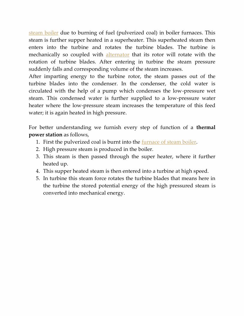
steam boiler due to burning of fuel (pulverized coal) in boiler furnaces. This
steam is further supper heated in a superheater. This superheated steam then
enters into the turbine and rotates the turbine blades. The turbine is
mechanically so coupled with alternator that its rotor will rotate with the
rotation of turbine blades. After entering in turbine the steam pressure
suddenly falls and corresponding volume of the steam increases.
After imparting energy to the turbine rotor, the steam passes out of the
turbine blades into the condenser. In the condenser, the cold water is
circulated with the help of a pump which condenses the low-pressure wet
steam. This condensed water is further supplied to a low-pressure water
heater where the low-pressure steam increases the temperature of this feed
water; it is again heated in high pressure.
For better understanding we furnish every step of function of a thermal
power station as follows,
1. First the pulverized coal is burnt into the furnace of steam boiler.
2. High pressure steam is produced in the boiler.
3. This steam is then passed through the super heater, where it further
heated up.
4. This supper heated steam is then entered into a turbine at high speed.
5. In turbine this steam force rotates the turbine blades that means here in
the turbine the stored potential energy of the high pressured steam is
converted into mechanical energy.

Line Diagram of Power Plant
1. After rotating the turbine blades, the steam has lost its high pressure,
passes out of turbine blades and enters into a condenser.
2. In the condenser the cold water is circulated with help of pump which
condenses the low pressure wet steam.
3. This condensed water is then further supplied to low pressure water
heater where the low pressure steam increases the temperature of this
feed water, it is then again heated in a high pressure heater where the
high pressure of steam is used for heating.
4. The turbine in thermal power station acts as a prime mover of
the alternator.

Overview of Thermal Power Plant
A typical Thermal Power Station Operates on a Cycle which is shown below.
The working fluid is water and steam. This is called feed water and steam
cycle. The ideal Thermodynamic Cycle to which the operation of a Thermal
Power Station closely resembles is the RANKINE CYCLE.
In a steam boiler, the water is heated up by burning the fuel in the air in the
furnace, and the function of the boiler is to give dry superheated steam at the
required temperature. The steam so produced is used in driving the steam
Turbines. This turbine is coupled to synchronous generator (usually three-
phase synchronous alternator), which generates electrical energy. The exhaust
steam from the turbine is allowed to condense into water in steam condenser
of turbine, which creates suction at very low pressure and allows the
expansion of the steam in the turbine to very low pressure. The principal
advantages of the condensing operation are the increased amount of energy
extracted per kg of steam and thereby increasing efficiency, and the
condensate which is fed into the boiler again reduces the amount of fresh feed
water.
The condensate along with some fresh makeup feed water is again fed into
the boiler by a pump (called the boiler feed pump). In the condenser, the
steam is condensed by cooling water. Cooling water recycles through the
cooling tower. This constitutes a cooling water circuit.
The ambient air is allowed to enter the boiler after dust filtration. Also, the
flue gas comes out of the boiler and gets exhausted into the atmosphere
through stacks. These constitute air and flue gas circuit. The flow of air and
also the static pressure inside the steam boiler (called draught) is maintained
by two fans called Forced Draught (FD) fan and Induced Draught (ID) fan.
The total scheme of a typical thermal power station along with different
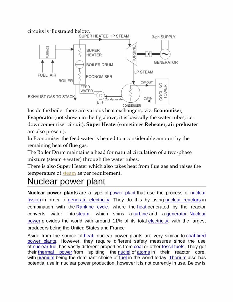
circuits is illustrated below.
Inside the boiler there are various heat exchangers, viz. Economiser,
Evaporator (not shown in the fig above, it is basically the water tubes, i.e.
downcomer riser circuit), Super Heater(sometimes Reheater, air preheater
are also present).
In Economiser the feed water is heated to a considerable amount by the
remaining heat of flue gas.
The Boiler Drum maintains a head for natural circulation of a two-phase
mixture (steam + water) through the water tubes.
There is also Super Heater which also takes heat from flue gas and raises the
temperature of steam as per requirement.
Nuclear power plant Nuclear power plants are a type of power plant that use the process of nuclear
fission in order to generate electricity. They do this by using nuclear reactors in
combination with the Rankine cycle, where the heat generated by the reactor
converts water into steam, which spins a turbine and a generator. Nuclear
power provides the world with around 11% of its total electricity, with the largest
producers being the United States and France
Aside from the source of heat, nuclear power plants are very similar to coal-fired power plants. However, they require different safety measures since the use of nuclear fuel has vastly different properties from coal or other fossil fuels. They get their thermal power from splitting the nuclei of atoms in their reactor core, with uranium being the dominant choice of fuel in the world today. Thorium also has potential use in nuclear power production, however it is not currently in use. Below is

the basic operation of a boiling water power plant, which shows the many components of a power plant, along with the generation of electricity.
Figure 2. A boiling water nuclear reactor in combination with the Rankine cycle forms the basis
of a nuclear power plant.[3]
Components and Operation
Nuclear Reactor
main article
The reactor is a key component of a power plant, as it contains the fuel and its nuclear chain reaction, along with all of the nuclear waste products. The reactor is the heat source for the power plant, just like the boiler is for a coal plant. Uranium is the dominant nuclear fuel used in nuclear reactors, and its fission reactions are what produce the heat within a reactor. This heat is then transferred to the reactor's coolant, which provides heat to other parts of the nuclear power plant.
Besides their use in power generation, there are other types of nuclear reactors that are used for plutoniummanufacturing, the propulsion of ships, aircraft and satellites, along with research and medical purposes.[4] The power plant encompasses not just the reactor, but also cooling towers, turbines, generators, and various safety systems. The reactor is what makes it differ from other external heat engines.

Steam Generation
The production of steam is common among all nuclear power plants, but the way this is done varies immensely.
Figure 3. Steam turbine in a power plant.[5]
The most common power plants in the world use pressurized water reactors, which use two loops of circling water to produce steam.[6] The first loop carries extremely hot liquid water to a heat exchanger, where water at a lower pressure is circulated. It then heats up and boils to steam, and can then be sent to the turbine section.
Boiling water reactors, the second most common reactor in power generation, heat the water in the core directly to steam, as seen in Figure 2.[6]
Turbine and Generator
Figure 4. Two cooling towers of a nuclear power plant.[7]
Once steam has been produced, it travels at high pressures and speeds through one or more turbines. These get up to extremely high speeds, causing the steam to lose energy, therefore, condensing back to a cooler liquid water. The rotation of the turbines is used to spin an electric generator, which produces electricity that is sent out the the electrical grid.[8]

Cooling Towers
Perhaps the most iconic symbol of a nuclear power plant is the cooling towers, seen in Figure 4. They work to reject waste heat to the atmosphere by the transfer of heat from hot water (from the turbine section) to the cooler outside air.[4] Hot water cools in contact with the air and a small portion, around 2%, evaporates and raises up through the top. Moreover, these plants do not release any carbon dioxide—the primary greenhouse gas that contributes to climate change. Click here to see how a cooling tower works.
Many nuclear power plants simply put the waste heat into a river, lake or ocean instead of having cooling towers. Many other power plants like coal-fired power plants have cooling towers or these large bodies of water as well. This similarity exists because the process of turning heat into electricity is almost identical between nuclear power plants and coal-fired power plants.