epx2155 - titan tool
TRANSCRIPT

1104 © 2004 SprayTECH. All rights reserved. Form No. 0551544APrinted in the U. S. A.
EPX2155Piston Pump
SprayTECH1770 Fernbrook LaneMinneapolis, MN 55447
Technical Assistance: 1-800-292-4637Order Entry: 1-800-443-4500
Fax: 1-800-525-9501
www.spraytechinc.com
Owner’s Manual
Model Numbers:0551010 Stand0551012 Upright Cart0551013 Low Boy Cart
Table of ContentsSafety Precautions .................................................................2Specifications .........................................................................3General Description ...............................................................4Operation ................................................................................4
Setup ....................................................................................4Preparing to Paint .................................................................4Painting.................................................................................5Pressure Relief Procedure ...................................................5
Spraying ..................................................................................6Spraying Technique ..............................................................6Practice.................................................................................6
Cleanup ...................................................................................6Cleaning the Spray Tip .........................................................7
Maintenance............................................................................7General Repair and Service Notes.......................................7Replacing the PRIME/SPRAY Valve.....................................7Replacing the Filters.............................................................8Replacing the Motor Assembly .............................................8Replacing the Motor Brushes ...............................................9Replacing the Gears.............................................................9Replacing the Transducer.....................................................9Servicing the Fluid Section .................................................10
Troubleshooting ...................................................................12Parts List ...............................................................................18
Main Assembly....................................................................18Motor Assembly ..................................................................19Suction Set Assembly.........................................................19Labels .................................................................................19Gear Box Assembly ............................................................20Stand Assembly ..................................................................21Upright Cart Assembly........................................................21Fluid Section Assembly ......................................................22Low Boy Cart Assembly......................................................23Electrical Schematic ...........................................................23Accessories ........................................................................24
Limited Warranty ..................................................................24
Safety PrecautionsThis manual contains information that must be read andunderstood before using the equipment. When you come to anarea that has one of the following symbols, pay particularattention and make certain to heed the safeguard.
This symbol indicates a potential hazard that may causeserious injury or loss of life. Important safety information willfollow.
This symbol indicates a potential hazard to you or to theequipment. Important information that tells how to preventdamage to the equipment or how to avoid causes of minorinjuries will follow.
HAZARD: Injection injury - A high pressure fluid streamproduced by this equipment can pierce theskin and underlying tissues, leading to seriousinjury and possible amputation. See aphysician immediately.
DO NOT TREAT AN INJECTION INJURY AS A SIMPLECUT! Injection can lead to amputation. See a physicianimmediately.The maximum operating range of the sprayer is 3000 PSI/20.7 MPa fluid pressure.
PREVENTION:• NEVER aim the gun at any part of the body.
WARNING
NOTE: Notes give important information which shouldbe given special attention.
CAUTION
WARNING
2 © SprayTECH. All rights reserved.
• NEVER allow any part of the body to touch the fluid stream.DO NOT allow body to touch a leak in the fluid hose.
• NEVER put hand in front of the gun. Gloves will notprovide protection against an injection injury.
• ALWAYS lock gun trigger, shut pump off, and release allpressure before servicing, cleaning tip or guard, changingtip, or leaving unattended. Pressure will not be releasedby turning off the motor. The PRIME/SPRAY valve handlemust be turned to PRIME to relieve the pressure. Refer tothe PRESSURE RELIEF PRESSURE described in thepump manual.
• ALWAYS keep tip guard in place while spraying. The tipguard provides some protection but is mainly a warningdevice.
• ALWAYS remove the spray tip before flushing or cleaningthe system.
• Paint hose can develop leaks from wear, kinking andabuse. A leak can inject material into the skin. Inspectthe hose before each use.
• NEVER use a spray gun without a working trigger lockand trigger guard in place.
• All accessories must be rated at or above the maximumoperating pressure range of the airless sprayer. Thisincludes spray tips, guns, extensions, and hose.
HAZARD: EXPLOSION AND FIRE - Solvent and paintfumes can explode or ignite. Severe injuryand/or property damage can occur.
PREVENTION:• Provide extensive exhaust and fresh air introduction to
keep the air within the spray area free from accumulationof flammable vapors.
• Avoid all ignition sources such as static electricity sparks,electrical appliances, flames, pilot lights, hot objects, andsparks from connecting and disconnecting power cords orworking light switches.
• Do not smoke in spray area.• Fire extinguisher must be present and in good working
order.• Place pump at least 25 feet (7.6 m) from the spray object
in a well ventilated area (add more hose if necessary).Flammable vapors are often heavier than air. Floor areamust be extremely well ventilated. The pump containsarcing parts that emit sparks and can ignite vapors.
• The equipment and objects in and around the spray areamust be properly grounded to prevent static sparks.
• Use only conductive or grounded high-pressure fluid hose.Gun must be grounded through hose connections.
• Power cord must be connected to a grounded circuit.• Always flush unit into separate metal container, at low
pump pressure, with spray tip removed. Hold gun firmlyagainst side of container to ground container and preventstatic sparks.
• Follow material and solvent manufacturer's warnings andinstructions.
• Use extreme caution when using materials with aflashpoint below 70° F (21° C). Flashpoint is thetemperature at which a fluid can produce enough vaporsto ignite.
• Plastic can cause static sparks. Never hang plastic toenclose spray area. Do not use plastic drop cloths whenspraying flammable materials.
• Use lowest possible pressure to flush equipment.
NOTE TO PHYSICIAN:Injection into the skin is a traumatic injury. It isimportant to treat the injury as soon as possible. DONOT delay treatment to research toxicity. Toxicity is aconcern with some coatings injected directly into theblood stream. Consultation with a plastic surgeon orreconstructive hand surgeon may be advisable.
GAS ENGINE (WHERE APPLICABLE)Always place sprayer outside of structure in fresh air. Keep allsolvents away from engine exhaust. Never fill fuel tank with arunning or hot engine. Hot surface can ignite spilled fuel.Always attach ground wire from pump to a grounded object.Refer to engine owner’s manual for complete safetyinformation.
HAZARD: EXPLOSION HAZARD DUE TO INCOMPATIBLEMATERIALS - will cause severe injury orproperty damage.
PREVENTION:• Do not use materials containing bleach or chlorine.• Do not use halogenated hydrocarbon solvents such as
bleach, mildewcide, methylene chloride and 1,1,1 -trichloroethane. They are not compatible with aluminum.
• Contact your coating supplier about the compatibility ofmaterial with aluminum.
HAZARD: HAZARDOUS VAPORS - Paints, solvents,insecticides, and other materials can beharmful if inhaled or come in contact with body.Vapors can cause severe nausea, fainting, orpoisoning.
PREVENTION:• Use a respirator or mask if vapors can be inhaled. Read
all instructions supplied with the mask to be sure it willprovide the necessary protection.
• Wear protective eyewear.• Wear protective clothing as required by coating
manufacturer.
HAZARD: GENERAL - Can cause severe injury orproperty damage.
PREVENTION:• Read all instructions and safety precautions before
operating equipment.• Follow all appropriate local, state, and national codes
governing ventilation, fire prevention, and operation. • The United States Government Safety Standards have
been adopted under the Occupational Safety and HealthAct (OSHA). These standards, particularly part 1910 ofthe General Standards and part 1926 of the ConstructionStandards, should be consulted.
• Use only manufacturer authorized parts. User assumesall risks and liabilities when using parts that do not meetthe minimum specifications and safety devices of thepump manufacturer.
• Before each use, check all hoses for cuts, leaks, abrasionor bulging of cover. Check for damage or movement ofcouplings. Immediately replace hose if any of thoseconditions exist. Never repair a paint hose. Replace witha grounded high-pressure hose.
• All hoses, swivels, guns, and accessories must bepressure rated at or above the maximum operatingpressure range of the airless sprayer.
• Do not spray outdoors on windy days.• Wear clothing to keep paint off skin and hair.• Always unplug cord from outlet before working on
equipment.
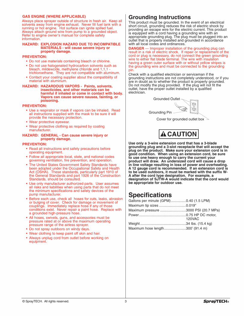
Grounding InstructionsThis product must be grounded. In the event of an electricalshort circuit, grounding reduces the risk of electric shock byproviding an escape wire for the electric current. This productis equipped with a cord having a grounding wire with anappropriate grounding plug. The plug must be plugged into anoutlet that is properly installed and grounded in accordancewith all local codes and ordinances.DANGER — Improper installation of the grounding plug canresult in a risk of electric shock. If repair or replacement of thecord or plug is necessary, do not connect the green groundingwire to either flat blade terminal. The wire with insulationhaving a green outer surface with or without yellow stripes isthe grounding wire and must be connected to the groundingpin.Check with a qualified electrician or serviceman if thegrounding instructions are not completely understood, or if youare in doubt as to whether the product is properly grounded.Do not modify the plug provided. If the plug will not fit theoutlet, have the proper outlet installed by a qualifiedelectrician.
Use only a 3-wire extension cord that has a 3-bladegrounding plug and a 3-slot receptacle that will accept theplug on the product. Make sure your extension cord is ingood condition. When using an extension cord, be sureto use one heavy enough to carry the current yourproduct will draw. An undersized cord will cause a dropin line voltage resulting in loss of power and overheating.A 12 gauge cord is recommended. If an extension cord isto be used outdoors, it must be marked with the suffix W-A after the cord type designation. For example, adesignation of SJTW-A would indicate that the cord wouldbe appropriate for outdoor use.
SpecificationsGallons per minute (GPM) ...............0.40 (1.5 LPM)Maximum tip sizes ...........................0.019”Maximum pressure ..........................3000 PSI (20.7 MPa)Power...............................................0.75 HP DC motor,
120VACWeight ..............................................34 lbs. (15.4 kg)Maximum hose length......................300’ (91.4 m)
CAUTION
Grounded Outlet
Grounding Pin
Cover for grounded outlet box
© SprayTECH. All rights reserved. 3
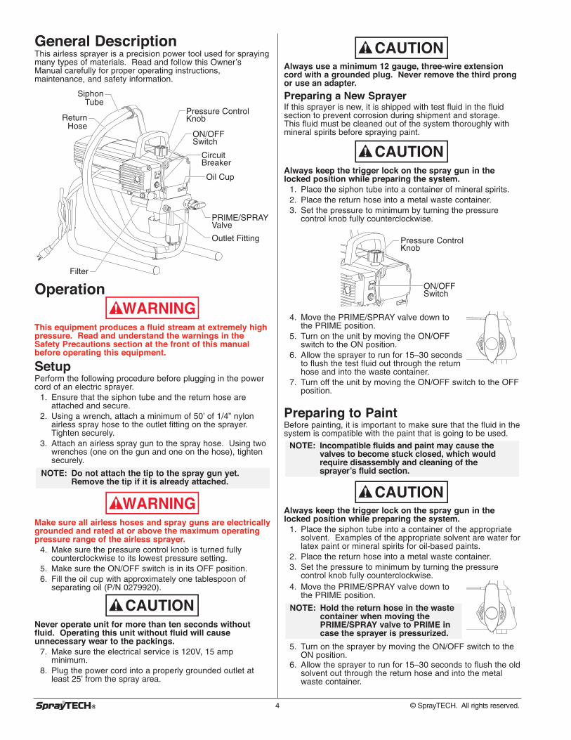
General DescriptionThis airless sprayer is a precision power tool used for sprayingmany types of materials. Read and follow this Owner’sManual carefully for proper operating instructions,maintenance, and safety information.
Operation
This equipment produces a fluid stream at extremely highpressure. Read and understand the warnings in theSafety Precautions section at the front of this manualbefore operating this equipment.
SetupPerform the following procedure before plugging in the powercord of an electric sprayer.
1. Ensure that the siphon tube and the return hose areattached and secure.
2. Using a wrench, attach a minimum of 50’ of 1/4” nylonairless spray hose to the outlet fitting on the sprayer.Tighten securely.
3. Attach an airless spray gun to the spray hose. Using twowrenches (one on the gun and one on the hose), tightensecurely.
Make sure all airless hoses and spray guns are electricallygrounded and rated at or above the maximum operatingpressure range of the airless sprayer.
4. Make sure the pressure control knob is turned fullycounterclockwise to its lowest pressure setting.
5. Make sure the ON/OFF switch is in its OFF position.6. Fill the oil cup with approximately one tablespoon of
separating oil (P/N 0279920).
Never operate unit for more than ten seconds withoutfluid. Operating this unit without fluid will causeunnecessary wear to the packings.
7. Make sure the electrical service is 120V, 15 ampminimum.
8. Plug the power cord into a properly grounded outlet atleast 25’ from the spray area.
CAUTION
WARNING
NOTE: Do not attach the tip to the spray gun yet.Remove the tip if it is already attached.
WARNING
Pressure Control Knob
ON/OFF Switch
PRIME/SPRAY Valve
Outlet Fitting
Circuit Breaker
Oil Cup
Siphon Tube
Return Hose
Filter
4 © SprayTECH. All rights reserved.
Always use a minimum 12 gauge, three-wire extensioncord with a grounded plug. Never remove the third prongor use an adapter.
Preparing a New SprayerIf this sprayer is new, it is shipped with test fluid in the fluidsection to prevent corrosion during shipment and storage.This fluid must be cleaned out of the system thoroughly withmineral spirits before spraying paint.
Always keep the trigger lock on the spray gun in thelocked position while preparing the system.
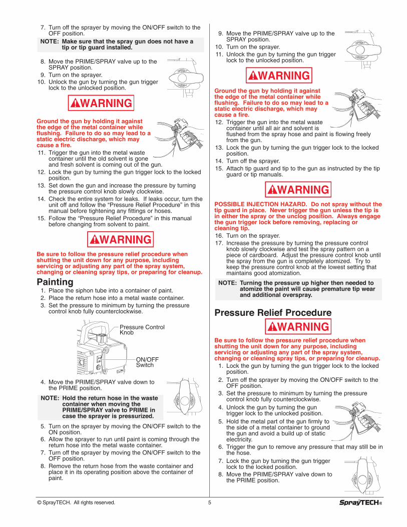
1. Place the siphon tube into a container of mineral spirits.2. Place the return hose into a metal waste container.3. Set the pressure to minimum by turning the pressure
control knob fully counterclockwise.
4. Move the PRIME/SPRAY valve down tothe PRIME position.
5. Turn on the unit by moving the ON/OFFswitch to the ON position.
6. Allow the sprayer to run for 15–30 secondsto flush the test fluid out through the returnhose and into the waste container.
7. Turn off the unit by moving the ON/OFF switch to the OFFposition.
Preparing to PaintBefore painting, it is important to make sure that the fluid in thesystem is compatible with the paint that is going to be used.
Always keep the trigger lock on the spray gun in thelocked position while preparing the system.
1. Place the siphon tube into a container of the appropriatesolvent. Examples of the appropriate solvent are water forlatex paint or mineral spirits for oil-based paints.
2. Place the return hose into a metal waste container.3. Set the pressure to minimum by turning the pressure
control knob fully counterclockwise.4. Move the PRIME/SPRAY valve down to
the PRIME position.
5. Turn on the sprayer by moving the ON/OFF switch to theON position.
6. Allow the sprayer to run for 15–30 seconds to flush the oldsolvent out through the return hose and into the metalwaste container.
NOTE: Hold the return hose in the wastecontainer when moving thePRIME/SPRAY valve to PRIME incase the sprayer is pressurized.
CAUTION
NOTE: Incompatible fluids and paint may cause thevalves to become stuck closed, which wouldrequire disassembly and cleaning of thesprayer’s fluid section.
Pressure Control Knob
ON/OFF Switch
CAUTION
CAUTION
7. Turn off the sprayer by moving the ON/OFF switch to theOFF position.
8. Move the PRIME/SPRAY valve up to theSPRAY position.
9. Turn on the sprayer.10. Unlock the gun by turning the gun trigger
lock to the unlocked position.
Ground the gun by holding it againstthe edge of the metal container whileflushing. Failure to do so may lead to astatic electric discharge, which maycause a fire.11. Trigger the gun into the metal waste
container until the old solvent is goneand fresh solvent is coming out of the gun.
12. Lock the gun by turning the gun trigger lock to the lockedposition.
13. Set down the gun and increase the pressure by turningthe pressure control knob slowly clockwise.
14. Check the entire system for leaks. If leaks occur, turn theunit off and follow the “Pressure Relief Procedure” in thismanual before tightening any fittings or hoses.
15. Follow the “Pressure Relief Procedure” in this manualbefore changing from solvent to paint.
Be sure to follow the pressure relief procedure whenshutting the unit down for any purpose, includingservicing or adjusting any part of the spray system,changing or cleaning spray tips, or preparing for cleanup.
Painting1. Place the siphon tube into a container of paint.2. Place the return hose into a metal waste container.3. Set the pressure to minimum by turning the pressure
control knob fully counterclockwise.
4. Move the PRIME/SPRAY valve down tothe PRIME position.
5. Turn on the sprayer by moving the ON/OFF switch to theON position.
6. Allow the sprayer to run until paint is coming through thereturn hose into the metal waste container.
7. Turn off the sprayer by moving the ON/OFF switch to theOFF position.
8. Remove the return hose from the waste container andplace it in its operating position above the container ofpaint.
NOTE: Hold the return hose in the wastecontainer when moving thePRIME/SPRAY valve to PRIME incase the sprayer is pressurized.
Pressure Control Knob
ON/OFF Switch
WARNING
WARNING
NOTE: Make sure that the spray gun does not have atip or tip guard installed.
9. Move the PRIME/SPRAY valve up to theSPRAY position.
10. Turn on the sprayer.11. Unlock the gun by turning the gun trigger
lock to the unlocked position.
Ground the gun by holding it againstthe edge of the metal container whileflushing. Failure to do so may lead to astatic electric discharge, which maycause a fire.12. Trigger the gun into the metal waste
container until all air and solvent isflushed from the spray hose and paint is flowing freelyfrom the gun.
13. Lock the gun by turning the gun trigger lock to the lockedposition.
14. Turn off the sprayer.15. Attach tip guard and tip to the gun as instructed by the tip
guard or tip manuals.
POSSIBLE INJECTION HAZARD. Do not spray without thetip guard in place. Never trigger the gun unless the tip isin either the spray or the unclog position. Always engagethe gun trigger lock before removing, replacing orcleaning tip.16. Turn on the sprayer.17. Increase the pressure by turning the pressure control
knob slowly clockwise and test the spray pattern on apiece of cardboard. Adjust the pressure control knob untilthe spray from the gun is completely atomized. Try tokeep the pressure control knob at the lowest setting thatmaintains good atomization.
Pressure Relief Procedure
Be sure to follow the pressure relief procedure whenshutting the unit down for any purpose, includingservicing or adjusting any part of the spray system,changing or cleaning spray tips, or preparing for cleanup.
1. Lock the gun by turning the gun trigger lock to the lockedposition.
2. Turn off the sprayer by moving the ON/OFF switch to theOFF position.
3. Set the pressure to minimum by turning the pressurecontrol knob fully counterclockwise.
4. Unlock the gun by turning the guntrigger lock to the unlocked position.
5. Hold the metal part of the gun firmly tothe side of a metal container to groundthe gun and avoid a build up of staticelectricity.
6. Trigger the gun to remove any pressure that may still be inthe hose.
7. Lock the gun by turning the gun triggerlock to the locked position.
8. Move the PRIME/SPRAY valve down tothe PRIME position.
WARNING
NOTE: Turning the pressure up higher then needed toatomize the paint will cause premature tip wearand additional overspray.
WARNING
WARNING
© SprayTECH. All rights reserved. 5
Spraying
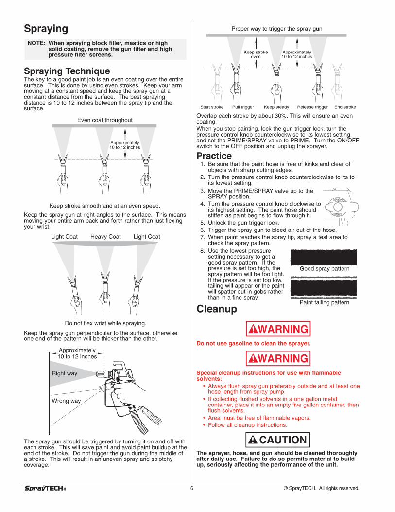
Spraying TechniqueThe key to a good paint job is an even coating over the entiresurface. This is done by using even strokes. Keep your armmoving at a constant speed and keep the spray gun at aconstant distance from the surface. The best sprayingdistance is 10 to 12 inches between the spray tip and thesurface.
Keep the spray gun at right angles to the surface. This meansmoving your entire arm back and forth rather than just flexingyour wrist.
Keep the spray gun perpendicular to the surface, otherwiseone end of the pattern will be thicker than the other.
The spray gun should be triggered by turning it on and off witheach stroke. This will save paint and avoid paint buildup at theend of the stroke. Do not trigger the gun during the middle ofa stroke. This will result in an uneven spray and splotchycoverage.
Approximately10 to 12 inches
Right way
Wrong way
Heavy Coat
Do not flex wrist while spraying.
Light Coat Light Coat
Keep stroke smooth and at an even speed.
Even coat throughout
Approximately10 to 12 inches
NOTE: When spraying block filler, mastics or highsolid coating, remove the gun filter and highpressure filter screens.
6 © SprayTECH. All rights reserved.
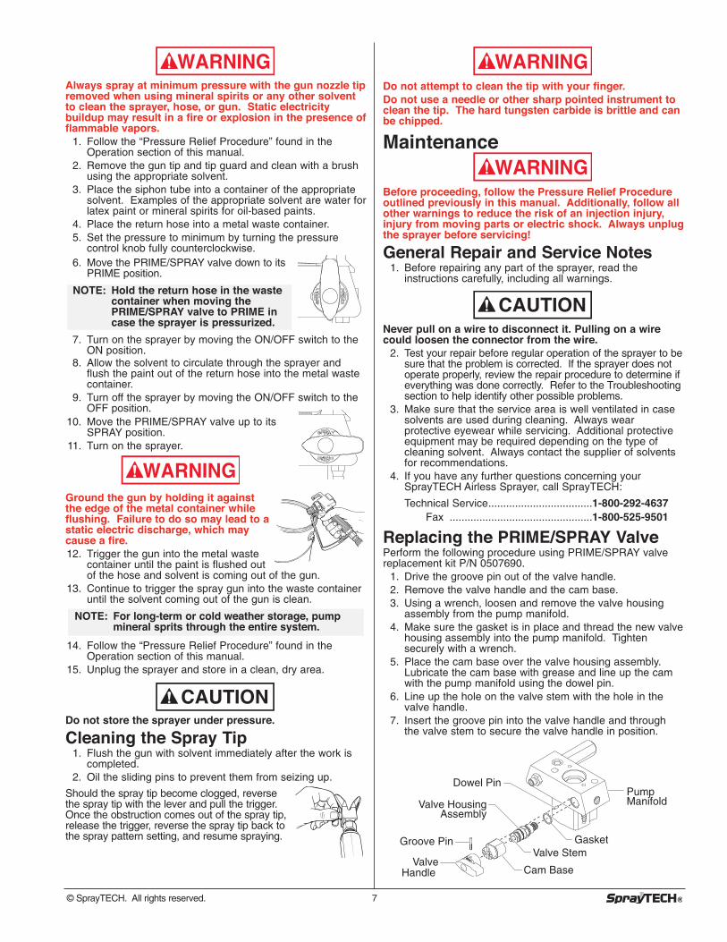
Overlap each stroke by about 30%. This will ensure an evencoating.When you stop painting, lock the gun trigger lock, turn thepressure control knob counterclockwise to its lowest settingand set the PRIME/SPRAY valve to PRIME. Turn the ON/OFFswitch to the OFF position and unplug the sprayer.
Practice1. Be sure that the paint hose is free of kinks and clear of
objects with sharp cutting edges.2. Turn the pressure control knob counterclockwise to its to
its lowest setting.3. Move the PRIME/SPRAY valve up to the
SPRAY position.4. Turn the pressure control knob clockwise to
its highest setting. The paint hose shouldstiffen as paint begins to flow through it.
5. Unlock the gun trigger lock.6. Trigger the spray gun to bleed air out of the hose.7. When paint reaches the spray tip, spray a test area to
check the spray pattern.8. Use the lowest pressure
setting necessary to get agood spray pattern. If thepressure is set too high, thespray pattern will be too light.If the pressure is set too low,tailing will appear or the paintwill spatter out in gobs ratherthan in a fine spray.
Cleanup
Do not use gasoline to clean the sprayer.
Special cleanup instructions for use with flammablesolvents:
• Always flush spray gun preferably outside and at least onehose length from spray pump.
• If collecting flushed solvents in a one gallon metalcontainer, place it into an empty five gallon container, thenflush solvents.
• Area must be free of flammable vapors.• Follow all cleanup instructions.
The sprayer, hose, and gun should be cleaned thoroughlyafter daily use. Failure to do so permits material to buildup, seriously affecting the performance of the unit.
CAUTION
WARNING
WARNING
Good spray pattern
Paint tailing pattern
Proper way to trigger the spray gun
Approximately10 to 12 inches
Keep strokeeven
Start stroke End strokePull trigger Release triggerKeep steady
Always spray at minimum pressure with the gun nozzle tipremoved when using mineral spirits or any other solventto clean the sprayer, hose, or gun. Static electricitybuildup may result in a fire or explosion in the presence offlammable vapors.
1. Follow the “Pressure Relief Procedure” found in theOperation section of this manual.
2. Remove the gun tip and tip guard and clean with a brushusing the appropriate solvent.
3. Place the siphon tube into a container of the appropriatesolvent. Examples of the appropriate solvent are water forlatex paint or mineral spirits for oil-based paints.
4. Place the return hose into a metal waste container.5. Set the pressure to minimum by turning the pressure
control knob fully counterclockwise.6. Move the PRIME/SPRAY valve down to its
PRIME position.
7. Turn on the sprayer by moving the ON/OFF switch to theON position.
8. Allow the solvent to circulate through the sprayer andflush the paint out of the return hose into the metal wastecontainer.
9. Turn off the sprayer by moving the ON/OFF switch to theOFF position.
10. Move the PRIME/SPRAY valve up to itsSPRAY position.
11. Turn on the sprayer.
Ground the gun by holding it againstthe edge of the metal container whileflushing. Failure to do so may lead to astatic electric discharge, which maycause a fire.12. Trigger the gun into the metal waste
container until the paint is flushed outof the hose and solvent is coming out of the gun.
13. Continue to trigger the spray gun into the waste containeruntil the solvent coming out of the gun is clean.
14. Follow the “Pressure Relief Procedure” found in theOperation section of this manual.
15. Unplug the sprayer and store in a clean, dry area.
Do not store the sprayer under pressure.
Cleaning the Spray Tip1. Flush the gun with solvent immediately after the work is
completed. 2. Oil the sliding pins to prevent them from seizing up.
Should the spray tip become clogged, reversethe spray tip with the lever and pull the trigger.Once the obstruction comes out of the spray tip,release the trigger, reverse the spray tip back tothe spray pattern setting, and resume spraying.
CAUTION
NOTE: For long-term or cold weather storage, pumpmineral sprits through the entire system.
WARNING
NOTE: Hold the return hose in the wastecontainer when moving thePRIME/SPRAY valve to PRIME incase the sprayer is pressurized.
WARNING
© SprayTECH. All rights reserved. 7
Do not attempt to clean the tip with your finger. Do not use a needle or other sharp pointed instrument toclean the tip. The hard tungsten carbide is brittle and canbe chipped.
Maintenance
Before proceeding, follow the Pressure Relief Procedureoutlined previously in this manual. Additionally, follow allother warnings to reduce the risk of an injection injury,injury from moving parts or electric shock. Always unplugthe sprayer before servicing!
General Repair and Service Notes1. Before repairing any part of the sprayer, read the
instructions carefully, including all warnings.
Never pull on a wire to disconnect it. Pulling on a wirecould loosen the connector from the wire.
2. Test your repair before regular operation of the sprayer to besure that the problem is corrected. If the sprayer does notoperate properly, review the repair procedure to determine ifeverything was done correctly. Refer to the Troubleshootingsection to help identify other possible problems.
3. Make sure that the service area is well ventilated in casesolvents are used during cleaning. Always wearprotective eyewear while servicing. Additional protectiveequipment may be required depending on the type ofcleaning solvent. Always contact the supplier of solventsfor recommendations.
4. If you have any further questions concerning yourSprayTECH Airless Sprayer, call SprayTECH:
Technical Service...................................1-800-292-4637Fax ................................................1-800-525-9501
Replacing the PRIME/SPRAY ValvePerform the following procedure using PRIME/SPRAY valvereplacement kit P/N 0507690.
1. Drive the groove pin out of the valve handle.2. Remove the valve handle and the cam base.3. Using a wrench, loosen and remove the valve housing
assembly from the pump manifold.4. Make sure the gasket is in place and thread the new valve
housing assembly into the pump manifold. Tightensecurely with a wrench.
5. Place the cam base over the valve housing assembly.Lubricate the cam base with grease and line up the camwith the pump manifold using the dowel pin.
6. Line up the hole on the valve stem with the hole in thevalve handle.
7. Insert the groove pin into the valve handle and throughthe valve stem to secure the valve handle in position.
Dowel Pin
Groove PinValve Stem
Gasket
Pump ManifoldValve Housing
Assembly
Valve Handle Cam Base
CAUTION
WARNING
WARNING
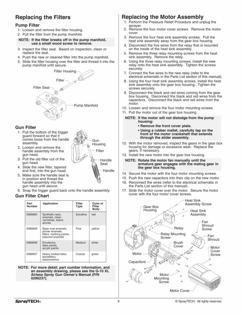
Replacing the Filters Pump Filter
1. Loosen and remove the filter housing.2. Pull the filter from the pump manifold.
3. Inspect the filter seal. Based on inspection, clean orreplace the seal.
4. Push the new or cleaned filter into the pump manifold.5. Slide the filter housing over the filter and thread it into the
pump manifold until secure.
Gun Filter1. Pull the bottom of the trigger
guard forward so that itcomes loose from the handleassembly.
2. Loosen and remove thehandle assembly from thegun head.
3. Pull the old filter out of thegun head.
4. Slide the new filter, taperedend first, into the gun head.
5. Make sure the handle seal isin position and thread thehandle assembly into thegun head until secure.
6. Snap the trigger guard back onto the handle assembly.
Gun Filter Chart
NOTE: For more detail, part number information, andan assembly drawing, please see the G-10 XLAirless Spray Gun Owner's Manual (P/N0296237).
Part Number
Application FilterType
Color ofFilter Body
0089960 Synthetic resin,enamels, cleanvarnishes, stainsazures
Extrafine red
0089959 Base coat enamels,primer enamels,fillers, marking paints,textured enamels
Fine yellow
0089958 Emulsions,latex paints,acrylic paints
Medium white
0089957 Heavy bodied latex, blockfillers, elastometrics
Coarse green
Gun Housing
Filter
Handle
Handle Seal
Filter Housing
Filter
Filter Seal
Pump Manifold
NOTE: If the filter breaks off in the pump manifold,use a small wood screw to remove.
8 © SprayTECH. All rights reserved.
Replacing the Motor Assembly1. Perform the Pressure Relief Procedure and unplug the
sprayer.2. Remove the four motor cover screws. Remove the motor
cover.3. Remove the four heat sink assembly screws. Pull the
heat sink assembly away from the gear box housing.4. Disconnect the five wires from the relay that is mounted
on the inside of the heat sink assembly.5. Remove the three relay mounting screws from the heat
sink assembly. Remove the relay.6. Using the three relay mounting screws, install the new
relay onto the heat sink assembly. Tighten the screwssecurely.
7. Connect the five wires to the new relay (refer to theelectrical schematic in the Parts List section of this manual).
8. Using the four heat sink assembly screws, install the heatsink assembly onto the gear box housing. Tighten thescrews securely.
9. Disconnect the black and red wires coming from the gearbox housing. Disconnect the black and red wires from thecapacitors. Disconnect the black and red wires from themotor.
10. Loosen and remove the four motor mounting screws.11. Pull the motor out of the gear box housing.
12. With the motor removed, inspect the gears in the gear boxhousing for damage or excessive wear. Replace thegears, if necessary.
13. Install the new motor into the gear box housing.
14. Secure the motor with the four motor mounting screws.15. Push the new capacitors into their clip on the new motor.16. Reconnect the wires (refer to the electrical schematic in
the Parts List section of this manual).17. Slide the motor cover over the motor. Secure the motor
cover with the four motor cover screws.
Motor Cover Screw
Heat Sink Assembly Screw
Heat Sink Assembly
Fan Shroud Screw
Fan Shroud
Brush Cover
Relay
Relay Mounting Screw
Motor
Motor Mounting
Screw
Gear Box Housing
Capacitors
Motor Cover
BLACK
BLA
CK
RE
DR
ED
BLACKRED
RED
NOTE: Rotate the motor fan manually until thearmature gear engages with the mating gear inthe gear box housing.
NOTE: If the motor will not dislodge from the pumphousing:• Remove the front cover plate.• Using a rubber mallet, carefully tap on the
front of the motor crankshaft that extends through the slider assembly.
Replacing the Motor BrushesPerform this procedure using Motor Brush Kit P/N 0508645.
1. Perform the Pressure Relief Procedure and unplug thesprayer.
2. Loosen and remove the four motor cover screws.Remove the motor cover.
3. Loosen and remove the two fan shroud screws. Removethe fan shroud.
4. Using a small screwdriver, pry off the two plastic brushcovers.
5. Disconnect the black and red wires from the motorbrushes. Remove the motor brushes.
6. Install the new motor brushes and snap on the plasticbrush covers.
7. Reconnect the black and red wires from the motorbrushes (refer to the electrical schematic in the Parts Listsection of this manual).
8. Position the fan shroud over the motor fan. Secure thefan shroud with the two fan shroud screws.
9. Slide the motor cover over the motor. Secure the motorcover with the four motor cover screws.
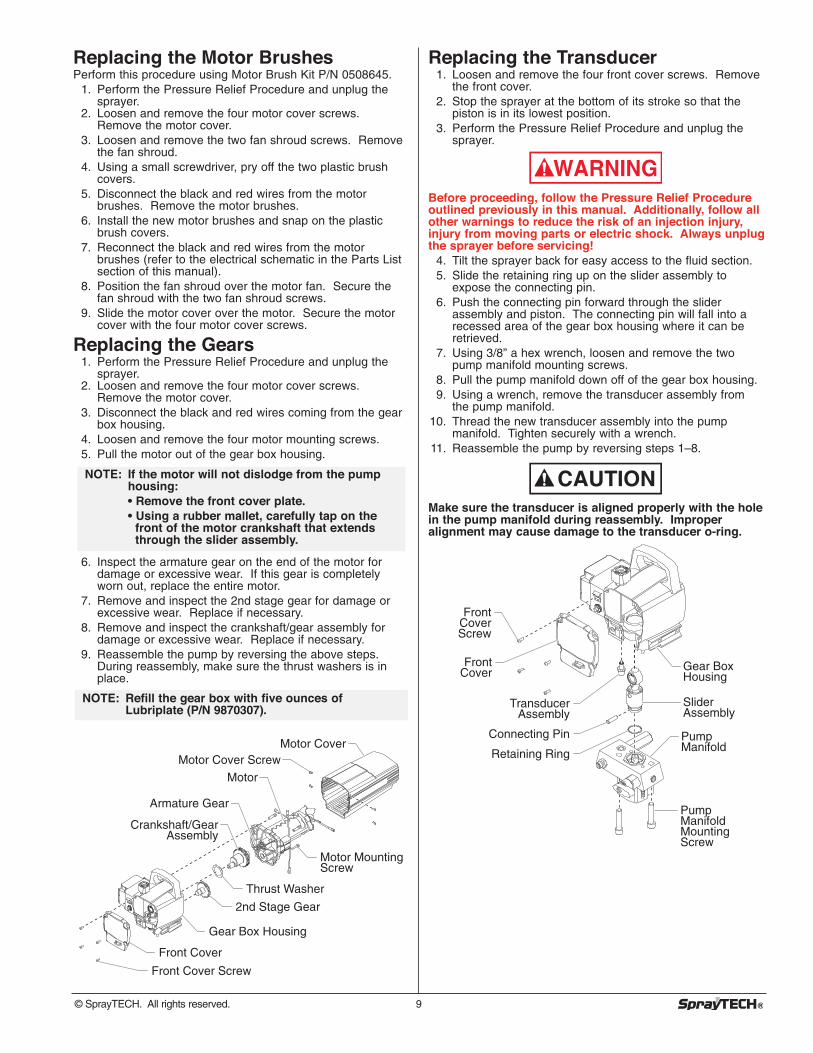
Replacing the Gears1. Perform the Pressure Relief Procedure and unplug the
sprayer.2. Loosen and remove the four motor cover screws.
Remove the motor cover.3. Disconnect the black and red wires coming from the gear
box housing.4. Loosen and remove the four motor mounting screws.5. Pull the motor out of the gear box housing.
6. Inspect the armature gear on the end of the motor fordamage or excessive wear. If this gear is completelyworn out, replace the entire motor.
7. Remove and inspect the 2nd stage gear for damage orexcessive wear. Replace if necessary.
8. Remove and inspect the crankshaft/gear assembly fordamage or excessive wear. Replace if necessary.
9. Reassemble the pump by reversing the above steps.During reassembly, make sure the thrust washers is inplace.
Front Cover
Gear Box Housing
Front Cover Screw
2nd Stage Gear
Thrust Washer
Motor Mounting Screw
Crankshaft/Gear Assembly
Armature Gear
Motor
Motor CoverMotor Cover Screw
NOTE: Refill the gear box with five ounces ofLubriplate (P/N 9870307).
NOTE: If the motor will not dislodge from the pumphousing:• Remove the front cover plate.• Using a rubber mallet, carefully tap on the
front of the motor crankshaft that extends through the slider assembly.
Replacing the Transducer1. Loosen and remove the four front cover screws. Remove
the front cover.2. Stop the sprayer at the bottom of its stroke so that the
piston is in its lowest position.3. Perform the Pressure Relief Procedure and unplug the
sprayer.
Before proceeding, follow the Pressure Relief Procedureoutlined previously in this manual. Additionally, follow allother warnings to reduce the risk of an injection injury,injury from moving parts or electric shock. Always unplugthe sprayer before servicing!
4. Tilt the sprayer back for easy access to the fluid section.5. Slide the retaining ring up on the slider assembly to
expose the connecting pin.6. Push the connecting pin forward through the slider
assembly and piston. The connecting pin will fall into arecessed area of the gear box housing where it can beretrieved.
7. Using 3/8” a hex wrench, loosen and remove the twopump manifold mounting screws.
8. Pull the pump manifold down off of the gear box housing.9. Using a wrench, remove the transducer assembly from
the pump manifold.10. Thread the new transducer assembly into the pump
manifold. Tighten securely with a wrench.11. Reassemble the pump by reversing steps 1–8.
Make sure the transducer is aligned properly with the holein the pump manifold during reassembly. Improperalignment may cause damage to the transducer o-ring.
Gear Box Housing
Slider Assembly
Pump Manifold
Pump Manifold Mounting Screw
Front Cover
Front Cover Screw
Transducer Assembly
Connecting Pin
Retaining Ring
CAUTION
WARNING
© SprayTECH. All rights reserved. 9
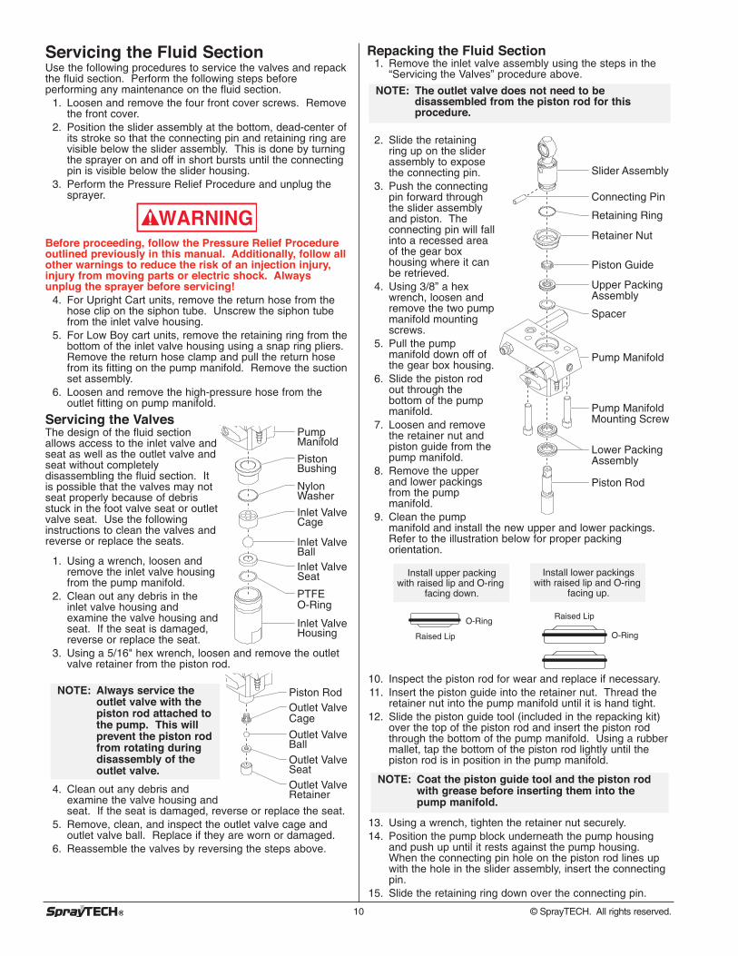
Servicing the Fluid SectionUse the following procedures to service the valves and repackthe fluid section. Perform the following steps beforeperforming any maintenance on the fluid section.
1. Loosen and remove the four front cover screws. Removethe front cover.
2. Position the slider assembly at the bottom, dead-center ofits stroke so that the connecting pin and retaining ring arevisible below the slider assembly. This is done by turningthe sprayer on and off in short bursts until the connectingpin is visible below the slider housing.
3. Perform the Pressure Relief Procedure and unplug thesprayer.
Before proceeding, follow the Pressure Relief Procedureoutlined previously in this manual. Additionally, follow allother warnings to reduce the risk of an injection injury,injury from moving parts or electric shock. Alwaysunplug the sprayer before servicing!
4. For Upright Cart units, remove the return hose from thehose clip on the siphon tube. Unscrew the siphon tubefrom the inlet valve housing.
5. For Low Boy cart units, remove the retaining ring from thebottom of the inlet valve housing using a snap ring pliers.Remove the return hose clamp and pull the return hosefrom its fitting on the pump manifold. Remove the suctionset assembly.
6. Loosen and remove the high-pressure hose from theoutlet fitting on pump manifold.
Servicing the ValvesThe design of the fluid sectionallows access to the inlet valve andseat as well as the outlet valve andseat without completelydisassembling the fluid section. Itis possible that the valves may notseat properly because of debrisstuck in the foot valve seat or outletvalve seat. Use the followinginstructions to clean the valves andreverse or replace the seats.
1. Using a wrench, loosen andremove the inlet valve housingfrom the pump manifold.
2. Clean out any debris in theinlet valve housing andexamine the valve housing andseat. If the seat is damaged,reverse or replace the seat.
3. Using a 5/16" hex wrench, loosen and remove the outletvalve retainer from the piston rod.
4. Clean out any debris andexamine the valve housing andseat. If the seat is damaged, reverse or replace the seat.
5. Remove, clean, and inspect the outlet valve cage andoutlet valve ball. Replace if they are worn or damaged.
6. Reassemble the valves by reversing the steps above.
NOTE: Always service theoutlet valve with thepiston rod attached tothe pump. This willprevent the piston rodfrom rotating duringdisassembly of theoutlet valve.
Outlet Valve Retainer
Outlet Valve Seat
Outlet Valve Ball
Outlet Valve Cage
Piston Rod
Inlet Valve Housing
PTFE O-Ring
Inlet Valve Seat
Inlet ValveBall
Inlet ValveCage
Nylon Washer
Piston Bushing
Pump Manifold
WARNING
10 © SprayTECH. All rights reserved.
Repacking the Fluid Section1. Remove the inlet valve assembly using the steps in the
“Servicing the Valves” procedure above.
2. Slide the retainingring up on the sliderassembly to exposethe connecting pin.
3. Push the connectingpin forward throughthe slider assemblyand piston. Theconnecting pin will fallinto a recessed areaof the gear boxhousing where it canbe retrieved.
4. Using 3/8” a hexwrench, loosen andremove the two pumpmanifold mountingscrews.
5. Pull the pumpmanifold down off ofthe gear box housing.
6. Slide the piston rodout through thebottom of the pumpmanifold.
7. Loosen and removethe retainer nut andpiston guide from thepump manifold.
8. Remove the upperand lower packingsfrom the pumpmanifold.
9. Clean the pumpmanifold and install the new upper and lower packings.Refer to the illustration below for proper packingorientation.
10. Inspect the piston rod for wear and replace if necessary.11. Insert the piston guide into the retainer nut. Thread the
retainer nut into the pump manifold until it is hand tight.12. Slide the piston guide tool (included in the repacking kit)
over the top of the piston rod and insert the piston rodthrough the bottom of the pump manifold. Using a rubbermallet, tap the bottom of the piston rod lightly until thepiston rod is in position in the pump manifold.
13. Using a wrench, tighten the retainer nut securely.14. Position the pump block underneath the pump housing
and push up until it rests against the pump housing.When the connecting pin hole on the piston rod lines upwith the hole in the slider assembly, insert the connectingpin.
15. Slide the retaining ring down over the connecting pin.
NOTE: Coat the piston guide tool and the piston rodwith grease before inserting them into thepump manifold.
Install lower packings with raised lip and O-ring
facing up.
Install upper packing with raised lip and O-ring
facing down.
O-Ring
O-RingRaised Lip
Raised Lip
Slider Assembly
Connecting Pin
Retaining Ring
Retainer Nut
Piston Guide
Upper Packing Assembly
Pump Manifold
Pump Manifold Mounting Screw
Piston Rod
Lower Packing Assembly
Spacer
NOTE: The outlet valve does not need to bedisassembled from the piston rod for thisprocedure.
Make sure the transducer is aligned properly with the holein the pump manifold during reassembly. Improperalignment may cause damage to the transducer gasket.16. Thread the pump manifold mounting screws through the
pump manifold and into the gear box housing. Tightensecurely.
17. Reassemble the inlet valve assembly into the pumpmanifold.
18. For Upright Cart units, thread the siphon tube into the inletvalve and tighten securely. Make sure to wrap the threads onthe down tube with PTFE tape before assembly. Replacethe return hose into the hose clip on the siphon tube.
19. For Low Boy cart units, insert the elbow on the suction setassembly into the bottom of the inlet valve housing. Pushthe retaining ring up into the groove inside the inlet valvehousing to secure the suction set assembly in position.Push the return hose onto the return hose fitting on thepump manifold and secure in position with the return hoseclamp.
20. Place the front cover on the gear box housing and securein position using the four front cover screws.
21. Turn on the sprayer by following the procedure in the“Operation” section of this manual and check for leaks.
NOTE: Repacking kit P/N 0551533 is available. Forbest results use all parts supplied in this kit.
CAUTION
© SprayTECH. All rights reserved. 11
Solution1. Plug the unit in.2. Reset the breaker.3. Turn the pressure control knob clockwise to
supply power to the unit and increase thepressure setting.
4. Inspect or take to a SprayTECH authorizedservice center.
5. Allow motor to cool.
1. Rotate the PRIME/SPRAY valve clockwiseto the PRIME position.
2. Check the siphon tube/suction setconnection and tighten or re-tape theconnection with PTFE tape.
3. Remove the pump filter element and clean.Remove the inlet screen and clean.
4. Remove the siphon tube/suction set andclean.
1. Replace the spray tip following theinstructions that came with the spray gun.
2. Replace the spray tip with a tip that has asmaller orifice following the instructions thatcame with the spray gun.
3. Turn the pressure control knob clockwise toincrease the pressure setting.
4. Remove the pump filter element and clean.Remove the gun filter and clean. Removethe inlet screen and clean.
5. Clean or replace the PRIME/SPRAY valve.
6. Check the siphon tube/suction setconnection and tighten or re-tape theconnection with PTFE tape.
7. Check for external leaks at all connections.Tighten connections, if necessary.
8. Clean the valves and service the fluidsection following the “Servicing the FluidSection” procedure in the Maintenancesection of this manual.
9. Reverse or replace the valve seatsfollowing the “Servicing the Fluid Section”procedure in the Maintenance section ofthis manual.
10. Take unit to a SprayTECH authorizedservice center.
1. Repack the pump following the “Servicingthe Fluid Section” procedure in theMaintenance section of this manual.
2. Replace the piston rod following the“Servicing the Fluid Section” procedure inthe Maintenance section of this manual.
Cause1. The unit is not plugged in.2. Tripped breaker.3. The pressure is set too low (pressure
control knob set at minimum settingdoes not supply power to unit).
4. Faulty or loose wiring.
5. Excessive motor temperature.
1. The PRIME/SPRAY valve is in theSPRAY position.
2. Air leak in the siphon tube/suction set.
3. The pump filter and/or inlet screen isclogged.
4. The siphon tube/suction set is clogged.
1. The spray tip is worn.
2. The spray tip is too large.
3. The pressure control knob is not setproperly.
4. The pump filter, gun filter, or inletscreen is clogged.
5. Material flows from the return hosewhen the PRIME/SPRAY valve is in theSPRAY position.
6. Air leak in the siphon tube/suction set.
7. There is external fluid leak.
8. There is an internal fluid section leak(packings are worn and/or dirty, valveballs are worn).
9. Worn valve seats
10. Motor powers but fails to rotate
1. The upper packings are worn.
2. The piston rod is worn.
TroubleshootingProblemThe unit will not run.
The unit will not prime.
The unit will not build ormaintain pressure.
Fluid leakage at the upper endof the fluid section.
12 © SprayTECH. All rights reserved.
© SprayTECH. All rights reserved. 13
TroubleshootingProblemExcessive surge at the spraygun.
Poor spray pattern.
The unit lacks power.
Cause1. Wrong type of airless spray hose.
2. The spray tip worn or too large.
3. Excessive pressure.
1. The spray tip is too large for thematerial being used.
2. Incorrect pressure setting.
3. Insufficient fluid delivery.4. The material being sprayed is too
viscous.
1. The pressure adjustment is too low.
2. Improper voltage supply.
Solution1. Replace hose with a minimum of 50’ of 1/4”
grounded textile braid airless paint sprayhose.
2. Replace the spray tip following theinstructions that came with the spray gun.
3. Rotate the pressure control knobcounterclockwise to decrease spraypressure.
1. Replace the spray tip with a new or smallerspray tip following the instructions thatcame with the spray gun.
2. Rotate the pressure control knob to adjustthe pressure for a proper spray pattern.
3. Clean all screens and filters.4. Add solvent to the material according to the
manufacturer's recommendations.
1. Rotate the pressure control knob clockwiseto increase the pressure setting.
2. Reconnect the input voltage for 120V AC.
14 © SprayTECH. Tous droits réservés.
Consignes de sécuritéLe présent manuel comprend des renseignements devant êtrelus attentivement avant toute utilisation de l'appareil. Lorsquel'un des symboles suivants apparaît, il est recommandé d'êtreparticulièrement attentif et de tenir compte des mesures desécurité indiquées.
Ce symbole indique un danger potentiel pouvant causer desblessures graves ou même mortelles. Des renseignementsimportants sur la sécurité sont également indiqués.
Ce symbole indique un danger potentiel pouvant causer desblessures corporelles ou des dommages à l'équipement. Desrenseignements importants sur la façon de prévenir toutdommage à l'équipement ou toute blessure corporelle mineuresont également indiqués.
DANGER: BLESSURES PAR PERFORATION - Le jet depeinture à haute pression produit par cetappareil peut perforer la peau et les tissussous-jacents et entraîner de sévères blessurespouvant nécessiter une amputation. Consultezimmédiatement un médecin.
NE PAS TRAITER UNE BLESSURE PAR PERFORATIONCOMME UNE SIMPLE COUPURE! Une perforation peutentraîner des risques d'amputation. Consultezimmédiatement un médecin.Pression de service maximale du fluide dans l’appareil :3000 lb/po2 / 20.7 MPa.
MESURES PRÉVENTIVES:• NE JAMAIS diriger le pistolet vers une quelconque partie
du corps. • NE JAMAIS mettre une quelconque partie du corps en
contact avec le jet de liquide. NE JAMAIS se mettre aucontact d'un jet de liquide provenant d'une fuite du flexibled'alimentation en liquide.
• NE JAMAIS placer votre main devant le pistolet. Desgants ne vous protégeront pas contre les risques deblessures par perforation.
• TOUJOURS verrouiller la gâchette du pistolet, fermer lapompe à liquide et décompresser l'appareil lorsque voustravaillez sur celui-ci, nettoyez le protecteur de tête,remplacez la tête de pulvérisation ou vous éloignez del'appareil. Couper le moteur ne décompresse pas l'appareil.Vous devez, pour le décompresser, placer le boutonAMORÇAGE/PULVÉRISATION en position AMORÇAGE.Reportez-vous, pour cela, à la PROCÉDURE DEDÉCOMPRESSION décrite dans de ce manuel.
• TOUJOURS s'assurer que le protecteur de tête est enplace lorsque vous pulvérisez. Le protecteur de tête offreune certaine protection contre les blessures par perforationmais sa principale fonction est d'ordre préventif.
• TOUJOURS ôter la tête de pulvérisation avant de purgerou nettoyer l'appareil.
• Le flexible d'alimentation en peinture peut fuir à la suited'une usure, de chocs ou de mauvais traitements. Unefuite peut entraîner une perforation de la peau. Inspecterle flexible avant chaque utilisation.
• NE JAMAIS utiliser un pistolet dont la gâchette n'est pasmunie d'un loquet ou un cran de sécurité qui soit en étatde fonctionner.
• Tous les accessoires doivent être homologués pour unepression égale ou supérieure à 3000 lb/po2 / 20.7 MPa.Cela s'applique, entre autres, aux têtes de pulvérisation,aux accessoires du pistolet et aux flexibles.
AVERTISSEMENT
NOTA : Les remarques donnent des renseignementsimportants requérant une attention particulière.
ATTENTION
AVERTISSEMENTDANGER: RISQUES D'EXPLOSION OU D'INCENDIE - Les
vapeurs dégagées par le solvant ou la peinturesont explosives et inflammables et peuventcauser des corporels sérieux ou dommagesmatériels.
MESURES PRÉVENTIVES:• Veiller à éviter toute accumulation de vapeurs
inflammables en vous assurant que la zone où lapulvérisation a lieu est suffisamment ventilée.
• Veiller à éviter la présence de toute source incandescentetelle qu'étincelle électrostatique, flamme nue, flamme-pilote, objet brûlant, cigarette et étincelle provenant dubranchement ou du débranchement d'un cordond'alimentation électrique ou d'un commutateur.
• Ne pas fumer dans la zone d’épandage.• Toujours avoir un extincteur en état de fonctionner à
portée de la main.• Placer la pompe à peinture à une distance d’au moins un
mètre (3 pi) (on recommande d’ailleurs une plus grandedistance) de l’objet qui doit être vaporisé dans une pièceséparée bien aérée, ou à une distance d’au moins sixmètres (20 pi) de celui-ci dans une zone bien aérée(utiliser d’autres tuyaux si nécessaires). Les vapeursinflammables sont souvent plus lourdes que l’air. Leplancher doit être extrêmement bien aéré. La pompe àpeinture contient des pièces pouvant créer des étincelleset enflammer les vapeurs présentes dans l’air.
• Le matériel utilisé, ainsi que les objets se trouvant àproximité de la zone de pulvérisation, doivent êtreconvenablement reliés à la terre afin d'éviter touteétincelle ou toute décharge électrostatique.
• N'utiliser que des flexibles d'alimentation en liquide àhaute pression conducteurs ou reliés à la terre dans lescas d'utilisation sans air comprimé. S'assurer que lepistolet est convenablement relié à la terre parl'intermédiaire du flexible.
• Le cordon d’alimentation doit être raccordé à un circuitmis à la terre.
• Toujours purger l’appareil dans un contenant métalliqueséparé, en s’assurant que la pompe soit à basse pressionet que le chapeau soit retiré. Tenir le pistolet fermementcontre la paroi du contenant pour mettre celui-ci à la terreet empêcher l’émission d’étincelles causées parl’électricité statique.
• Se conformer aux consignes et recommandations desécurité du fabricant du solvant ou du produit.
• S’entourer de toutes les précautions possibles lorsqu’onutilise des produits ayant un point d’éclair inférieur à 21°C (70 °F). Le point d’éclair d’un fluide est la températureà laquelle les vapeurs émanant du fluide peuvents’enflammer au contact d’une flamme ou d’une étincelle.
• Le plastique peut être une source d’étincelles provoquéespar l’électricité statique. Ne jamais utiliser une couvertureen plastique pour fermer une zone d’épandage ni utiliserdes toiles de protection en plastique lors de lapulvérisation de matières inflammables.
• Lorsque vous purgez l'appareil, veillez à utiliser à lapression minimale.
AVERTISSEMENT AUX MÉDECINS : Une perforationsous-cutanée constitue un traumatisme. Il estimportant de traiter la blessure de façon chirurgicaleaussitôt que possible. NE RETARDEZ PAS ce traitementpour des recherches de toxicité. La toxicité n'est unrisque que dans les cas où certains produits derevêtement pénètrent dans le flux sanguin. Il peut êtrenécessaire de faire appel à des soins de chirurgieplastique ou de reconstruction de la main.
Français
© SprayTECH. Tous droits réservés. 15
MOTEUR À ESSENCE (DANS LES CAS OÙ CELA S’APPLIQUE)Toujours placer la pompe à l’extérieur de la structure à l’airfrais. Garder tous les solvants loin de l’échappement dumoteur. Ne jamais remplir le réservoir à carburant lorsque lemoteur est en marche ou lorsqu’il est chaud ; les surfaceschaudes risquent d’enflammer le carburant déverséaccidentellement. Toujours raccorder un fil de mise à la terreentre la pompe et un objet mis à la terre, tel qu’une conduited’eau métallique. Se reporter au guide d’utilisation du moteurpour obtenir de plus amples renseignements concernant lasécurité.
DANGER: RISQUES D'EXPLOSION PAR INCOMPATIBILITÉDES MATÉRIAUX - Peuvent être à l'origine decorporels sérieux ou dommages matériels.
MESURES PRÉVENTIVES:• Ne pas utiliser de matériaux contenant des agents de
blanchiment ou du chlore.• Ne pas utiliser des solvants à base d’hydrocarbure
halogéné tels que l’agent anticryptogamique, le chlorurede méthylène et le trichloro-éthane-1,1,1. Ces produits nesont pas compatibles avec l’aluminium
• Communiquer avec votre fournisseur de revêtement pourconnaître la compatibilité du matériau avec l’aluminium.
DANGER: VAPEURS NOCIVES – la peinture, les solvants,les insecticides et autres matériaux peuventêtre nocifs lorsqu’ils sont inhalés ou en contactavec le corps. Les vapeurs peuvent causer unenausée importante, des évanouissements ouun empoisonnement.
MESURES PRÉVENTIVES:• Utiliser un respirateur ou un masque chaque fois qu'il y a
des risques d'inhalation de vapeurs. Lire attentivementtoutes les instructions se rapportant au masque pourvérifier que celui-ci vous assure une protection suffisantecontre les vapeurs toxiques.
• Porter des lunettes de protection.• Porter des vêtements de protection, conformément aux
directives du fabricant de revêtement.
DANGER: GÉNÉRALITÉS - Peut causer des dommagesmatériels ou corporels sérieux.
MESURES PRÉVENTIVES:• Avant d'utiliser tout équipement, lire attentivement toutes
les instructions et les consignes de sécurité • Toujours débrancher le moteur de l’alimentation électrique
avant d’effectuer des travaux sur l’appareil.• Se conformer à la législation locale, provinciale ou fédérale
pour tout ce qui concerne la ventilation, la prévention desincendies et les conditions générales d'utilisation.
• Les normes de sécurité du Gouvernement américain sontrégies par le Occupational Safety and Health Act (OSHA).Il est important de consulter ces normes, en particulier lasection 1910 sur le normes générales et la section 1926sur les des normes de la construction.
• N’utiliser que les pièces autorisées par le fabricant.L’utilisateur assume tous les risques et responsabilitéslorsqu’il utilise des pièces qui ne sont pas conformes auxcaractéristiques techniques minimales ainsi qu’auxdispositifs de sécurité du fabricant de la pompe.
• Vérifier, avant toute utilisation, que les flexibles neprésentent pas d'entaille ou de fuite, que le couvercle nesoit pas gonflé et que les raccords ne soient pasendommagés. Si le flexible a subi l'un des dommagesprécités, remplacez-le immédiatement. Ne jamais réparerun flexible d'alimentation en peinture. Le remplacer par unautre flexible mis à la terre.
• Tout flexible, raccord orientable, pistolet et accessoireutilisé avec cet appareil doit pouvoir fonctionner à unepression égale ou supérieure à 3000 lb/po2 / 20.7 MPa.
• Ne jamais pulvériser lorsqu'il vente.• Porter des vêtements pour protéger la peau et les
cheveux contre tout contact avec la peinture.
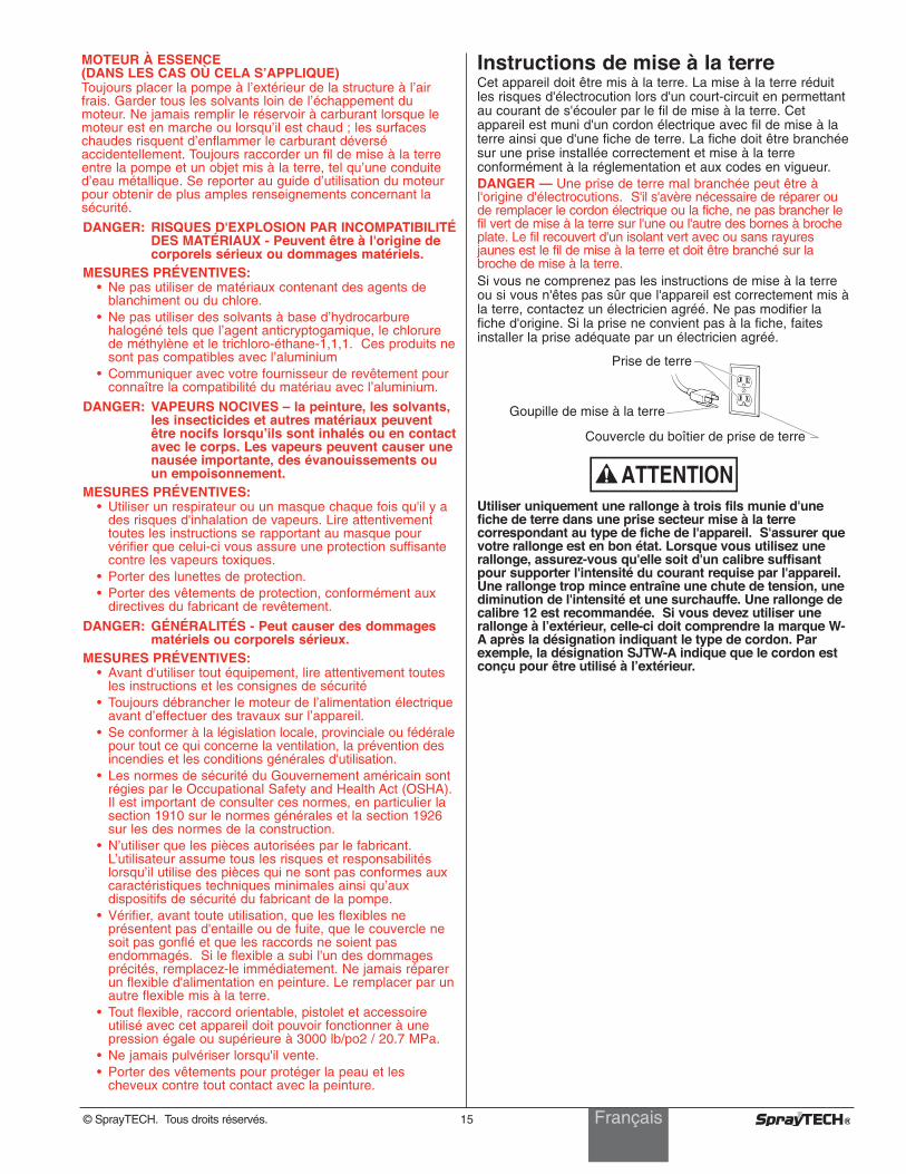
Instructions de mise à la terreCet appareil doit être mis à la terre. La mise à la terre réduitles risques d'électrocution lors d'un court-circuit en permettantau courant de s'écouler par le fil de mise à la terre. Cetappareil est muni d'un cordon électrique avec fil de mise à laterre ainsi que d'une fiche de terre. La fiche doit être branchéesur une prise installée correctement et mise à la terreconformément à la réglementation et aux codes en vigueur.DANGER — Une prise de terre mal branchée peut être àl'origine d'électrocutions. S'il s'avère nécessaire de réparer oude remplacer le cordon électrique ou la fiche, ne pas brancher lefil vert de mise à la terre sur l'une ou l'autre des bornes à brocheplate. Le fil recouvert d'un isolant vert avec ou sans rayuresjaunes est le fil de mise à la terre et doit être branché sur labroche de mise à la terre.Si vous ne comprenez pas les instructions de mise à la terreou si vous n'êtes pas sûr que l'appareil est correctement mis àla terre, contactez un électricien agréé. Ne pas modifier lafiche d'origine. Si la prise ne convient pas à la fiche, faitesinstaller la prise adéquate par un électricien agréé.
Utiliser uniquement une rallonge à trois fils munie d'unefiche de terre dans une prise secteur mise à la terrecorrespondant au type de fiche de l'appareil. S'assurer quevotre rallonge est en bon état. Lorsque vous utilisez unerallonge, assurez-vous qu'elle soit d'un calibre suffisantpour supporter l'intensité du courant requise par l'appareil.Une rallonge trop mince entraîne une chute de tension, unediminution de l'intensité et une surchauffe. Une rallonge decalibre 12 est recommandée. Si vous devez utiliser unerallonge à l’extérieur, celle-ci doit comprendre la marque W-A après la désignation indiquant le type de cordon. Parexemple, la désignation SJTW-A indique que le cordon estconçu pour être utilisé à l’extérieur.
ATTENTION
Prise de terre
Goupille de mise à la terre
Couvercle du boîtier de prise de terre
Français
16 ©SprayTECH. Todos los derechos reservados.
Precauciones de seguridadEste manual contiene información que debe leer y comprenderantes de usar el equipo. Cuando se encuentre con uno de lossiguientes símbolos, asegúrese de observar sus indicacionesde seguridad.
Este símbolo indica la existencia de un peligro potencial quepuede causar lesiones graves o la muerte. Después delmismo se incluye información de seguridad importante.
Este símbolo indica la existencia de un peligro potencial parausted o el equipo. Después del mismo se incluye informaciónimportante que indica la forma de evitar daños al equipo o laforma de prevenir lesiones menores.
PELIGRO: LESIÓN POR INYECCIÓN - La corriente depintura de alta presión que produce esteequipo puede perforar la piel y tejidossubyacentes, lo que conduciría a lesionesserias y una posible amputación. Consulte deinmediato a un médico.
NO TRATE LAS LESIONES POR INYECCIÓN COMO SIFUERAN SIMPLES CORTADAS! Una inyección puedeconducir a una amputación. Consulte de inmediato a unmédico.El rango de operación máximo de la unidad es 3000 PSI /20.7 MPa de presión de fluidos.PARA PREVENIR:
• NO dirija NUNCA la punta de la pistola hacia alguna partedel cuerpo.
• NO permita NUNCA que alguna parte del cuerpo tengacontacto con la corriente del fluido. EVITE tener contactocon corrientes de fluido que salgan de fugas que haya enla manguera.
• NO ponga NUNCA la mano enfrente de la manguera. Losguantes no ofrecen ninguna protección contra lesionespor inyección.
• Bloquee SIEMPRE el gatillo de la pistola, apague labomba de fluido y libere toda la presión antes de darmantenimiento, limpiar el protector de la boquilla, cambiarla boquilla o dejar desatendido el equipo. La presión nose liberará al apagar el motor. Para liberar la presióndebe girarse la perilla PRIME/SPRAY (cebar/atomizar)hasta la posición PRIME. Consulte el PROCEDIMIENTOPARA LIBERAR LA PRESIÓN que se describe en estemanual.
• Mantenga puesto SIEMPRE el protector de la boquillamientras atomice. El protector de la boquilla ofrece ciertaprotección contra lesiones por inyección pero esprincipalmente un dispositivo de advertencia.
• Quite SIEMPRE la boquilla del atomizador antes deenjuagar o limpiar el sistema.
• Pueden desarrollarse fugas en la manguera de pinturapor causa del desgaste, retorcimientos o el abuso. Unafuga es capaz de inyectar el material en la piel. Cada vezque use la manguera de pintura, inspecciónela antes.
• NO use nunca una pistola de atomización que no tengaun bloqueador o un protector de gatillo puesto y quefuncione.
• Todos los accesorios deben tener una capacidad de 3000lb/pulg2 / 20.7 MPa o mayor. Esto incluye las boquillasde atomizador, pistolas, extensiones y mangueras.
ADVERTENCIA
NOTA: los avisos contienen información importante,présteles especial atención.
PRECAUCION
ADVERTENCIA
Español
PELIGRO: EXPLOSIÓN O INCENDIO - Los vapores desolventes y pintura pueden explotar oincendiarse, causando con esto lesionesseveras y/o daños en la propiedad.
PARA PREVENIR:• Debe proveerse un escape y aire fresco para hacer que el
aire que está dentro del área de atomización se mantengalibre de acumulaciones de vapores inflamables.
• Evite todas las fuentes de ignición como son las chispaselectrostáticas, llamas abiertas, flamas de piloto, objetoscalientes, cigarros, y chispas que se generan al conectary desconectar las extensiones o de apagadores de luzque estén funcionando.
• No fume en la zona de trabajo.• Debe haber un equipo para extinguir incendios
permanentemente y en buenas condiciones.• Coloque la bomba para pintar a un mínimo de 1 m (de
preferencia más) en una habitación aparte, bien ventilada,alejada del objeto que va a pintar o a por lo menos 6 mde dicho objeto, en una zona bien ventilada (utilice unamanguera más larga, si es necesario). Los gasesinflamables a menudo son más pesados que el aire. Lazona del piso debe tener la debida ventilación. La bombapara pintar contiene piezas que forman arcos que emitenchispas y pueden encender los gases.
• El equipo que se utilice, así como los objetos que esténdentro y alrededor del área de atomización, debenconectarse a tierra de manera apropiada para prevenir lasdescargas eléctricas y las chispas.
• Use solamente mangueras para fluidos de alta presión,conductoras o conectadas a tierra, para aplicaciones sinaire. Asegúrese de que la pistola esté conectada a tierrade manera apropiada, mediante conexiones demanguera.
• El cable de alimentación debe enchufarse a un circuitoaterrado.
• Siempre enjuague la unidad en un recipiente de metal porseparado, con presión baja en la bomba y sin la boquilla.Sostenga la pistola firmemente contra el recipiente paraponerlo a tierra y evitar chispas estáticas.
• Siga las advertencias y avisos de seguridad del fabricantede los materiales y solventes.
• Tenga muchísimo cuidado al usar materiales cuyo puntode ignición sea inferior a 70° F (21° C). El punto deignición es la temperatura a la cual pueden encenderselos vapores emanados por un fluido al exponerlos allamas o chispas.
• El plástico puede causar chispas estáticas. Nuncacuelgue plástico en las ventanas ni en las puertas delárea donde va a pintar. No utilice plástico para protegerel piso cuando pinte materiales inflamables.
• Cuando enjuague el equipo utilice la presión más bajaposible.
MOTOR DE GAS (SEGÚN CORRESPONDA)Coloque siempre la bomba fuera del edificio, al aire libre.Mantenga todo solvente alejado del escape del motor. Nuncallene el tanque de combustible si el motor está encendido ocaliente. La superficie caliente puede encender el combustiblederramado. Conecte siempre un conductor de tierra desde launidad de la bomba a un objeto puesto a tierra, por ejemplouna tubería de agua metálica. Consulte el manual del motorpara obtener información completa de seguridad.
NOTA PARA EL MÉDICO: La inyección dentro de la pieles una lesión traumática. Es importante que la lesiónse trate quirúrgicamente tan pronto como sea posible .NO retrase el tratamiento por investigar la toxicidad.La toxicidad es motivo de preocupación con algunosrevestimientos que se inyectan directamente en lacorriente sanguínea. Es recomendable consultar a uncirujano plástico o reconstructor de manos.
©SprayTECH. Todos los derechos reservados. 17
PELIGRO: PELIGRO DE EXPLOSIÓN DEBIDO AMATERIALES INCOMPATIBLES - Podríacausar lesiones severas o daños en lapropiedad.
PARA PREVENIR:• No utilice materiales que contengan blanqueador o cloro.• No use solventes con hidrocarburos halogenados, tales
como productos para eliminar el moho, cloruro demetileno y 1,1,1 - tricloroetano. Estos no son compatiblescon el aluminio.
• Comuníquese con el proveedor del producto para obtenerinformación de compatibilidad con materiales de aluminio.
PELIGRO: GASES PELIGROSOS - Las pinturas, solventes,insecticidas y otros materiales pueden serperjudiciales si se inhalan o entran en contactocon el cuerpo. Los gases pueden causarnáusea, desmayos o envenenamiento graves.
PARA PREVENIR:• Use una mascarilla respiratoria o careta siempre que
exista la posibilidad de que se puedan inhalar vapores.Lea todas las intrucciones que vengan con la careta paraestar seguro de que se tendrá la protección necesariacontra la inhalación de vapores dañinos.
• Use gafas protectoras.• Use ropa de protección, según lo requiera el fabricante
del producto.
PELIGRO: GENERAL - Puede causar daños en lapropiedad o lesiones severas.
PARA PREVENIR:• Lea todas las instrucciones y advertencias de seguridad
antes de hacer funcionar cualquier equipo.• Desconecte siempre el motor del suministro eléctrico
antes de dar servicio al equipo.• Observe todos los códigos locales, estatales y nacionales
apropiados que rigen las medidas de ventilación,prevención de incendios y operación.
• Los Estándares de Seguridad del Gobierno de losEstados Unidos se han adoptado bajo el Acta deSeguridad y Salud Ocupacionales (OSHA por sus siglasen inglés). Deben consultarse estos estándares,particularmente la parte 1910 de los EstándaresGenerales y la parte 1926 de los Estándares de laConstrucción.
• Utilice únicamente piezas autorizadas por el fabricante.El usuario asume todos los riesgos y responsabilidades siusa piezas que no cumplen con las especificacionesmínimas y dispositivos de seguridad del fabricante de labomba.
• Antes de usarla cada vez, revise todas las mangueras paraver que no tengan cortadas, fugas, una cubierta desgastadapor abrasión o con abolladuras, así como uniones dañadaso que se hayan movido. Si existiera cualquiera de estascondiciones, reemplace la manguera inmediatamente. Norepare nunca una manguera de pintura. Reemplácela conotra manguera conectada a tierra.
• Todas las mangueras, soportes giratorios, pistolas yaccesorios que se usen con esta unidad deben tener unacapacidad de presión de 3000 lb/pulg2 / 20.7 MPa omayor.
• No atomice en días con viento.• Use ropa que evite el contacto de la pintura con la piel y
el cabello.
Español
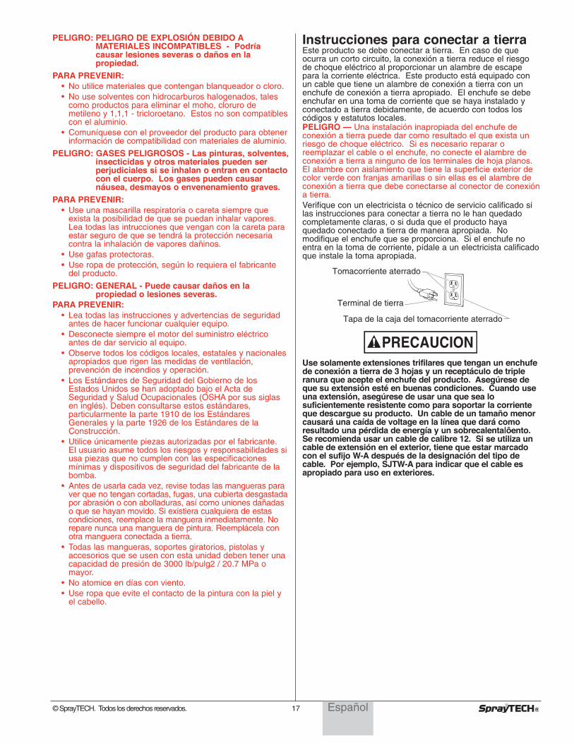
Instrucciones para conectar a tierraEste producto se debe conectar a tierra. En caso de queocurra un corto circuito, la conexión a tierra reduce el riesgode choque eléctrico al proporcionar un alambre de escapepara la corriente eléctrica. Este producto está equipado conun cable que tiene un alambre de conexión a tierra con unenchufe de conexión a tierra apropiado. El enchufe se debeenchufar en una toma de corriente que se haya instalado yconectado a tierra debidamente, de acuerdo con todos loscódigos y estatutos locales.PELIGRO — Una instalación inapropiada del enchufe deconexión a tierra puede dar como resultado el que exista unriesgo de choque eléctrico. Si es necesario reparar oreemplazar el cable o el enchufe, no conecte el alambre deconexión a tierra a ninguno de los terminales de hoja planos.El alambre con aislamiento que tiene la superficie exterior decolor verde con franjas amarillas o sin ellas es el alambre deconexión a tierra que debe conectarse al conector de conexióna tierra.Verifique con un electricista o técnico de servicio calificado silas instrucciones para conectar a tierra no le han quedadocompletamente claras, o si duda que el producto hayaquedado conectado a tierra de manera apropiada. Nomodifique el enchufe que se proporciona. Si el enchufe noentra en la toma de corriente, pídale a un electricista calificadoque instale la toma apropiada.
Use solamente extensiones trifilares que tengan un enchufede conexión a tierra de 3 hojas y un receptáculo de tripleranura que acepte el enchufe del producto. Asegúrese deque su extensión esté en buenas condiciones. Cuando useuna extensión, asegúrese de usar una que sea losuficientemente resistente como para soportar la corrienteque descargue su producto. Un cable de un tamaño menorcausará una caída de voltage en la línea que dará comoresultado una pérdida de energía y un sobrecalenta|ôento.Se recomienda usar un cable de calibre 12. Si se utiliza uncable de extensión en el exterior, tiene que estar marcadocon el sufijo W-A después de la designación del tipo decable. Por ejemplo, SJTW-A para indicar que el cable esapropiado para uso en exteriores.
PRECAUCION
Tomacorriente aterrado
Terminal de tierra
Tapa de la caja del tomacorriente aterrado
18 © SprayTECH. All rights reserved.
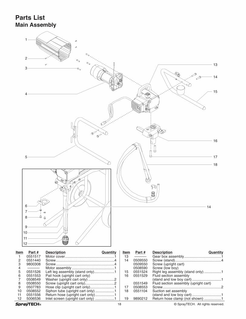
Parts List Main Assembly
1
3
4
5
9
6
7
8
10
11
12
2
17
18
16
13
14
14
15
Item Part # Description Quantity1 0551517 Motor cover.................................................12 0551440 Screw..........................................................43 9800308 Screw..........................................................44 ---------- Motor assembly ..........................................15 0551526 Left leg assembly (stand only)....................16 0551553 Pail hook (upright cart only)7 0508549 Washer (upright cart only) ..........................28 0508550 Screw (upright cart only).............................29 0507783 Hose clip (upright cart only)........................110 0508552 Siphon tube (upright cart only) ...................111 0551556 Return hose (upright cart only)...................112 5006536 Inlet screen (upright cart only) ...................1
Item Part # Description Quantity13 ---------- Gear box assembly.....................................114 0509550 Screw (stand)..............................................4
0509550 Screw (upright cart)0508590 Screw (low boy)
15 0551524 Right leg assembly (stand only) .................116 0551529 Fluid section assembly
(stand and low boy cart) .............................10551549 Fluid section assembly (upright cart)
17 0508553 Screw..........................................................218 0551104 Suction set assembly
(stand and low boy cart) .............................119 9890212 Return hose clamp (not shown) .................1
3
2
4
5
6
7
1
© SprayTECH. All rights reserved. 19
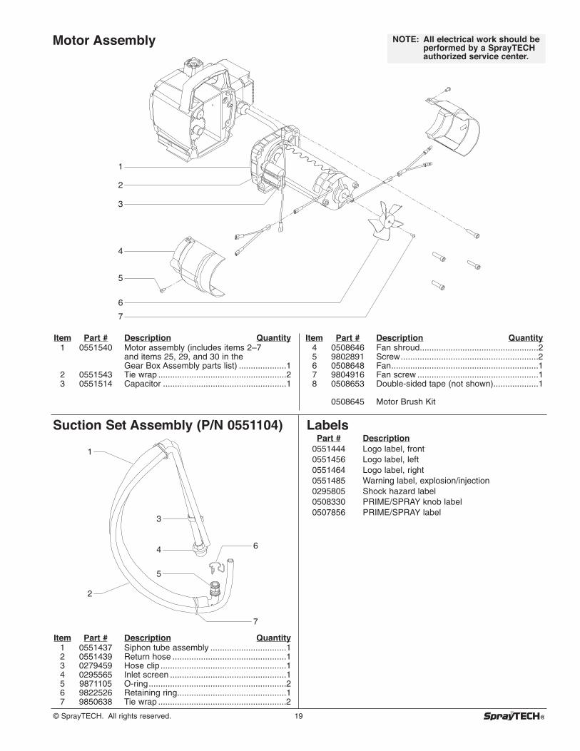
Item Part # Description Quantity1 0551540 Motor assembly (includes items 2–7
and items 25, 29, and 30 in the Gear Box Assembly parts list) ....................1
2 0551543 Tie wrap ......................................................23 0551514 Capacitor ....................................................1
Item Part # Description Quantity4 0508646 Fan shroud..................................................25 9802891 Screw..........................................................26 0508648 Fan..............................................................17 9804916 Fan screw ...................................................18 0508653 Double-sided tape (not shown)...................1
0508645 Motor Brush Kit
NOTE: All electrical work should beperformed by a SprayTECHauthorized service center.
Motor Assembly
Suction Set Assembly (P/N 0551104)
Item Part # Description Quantity1 0551437 Siphon tube assembly ................................12 0551439 Return hose ................................................13 0279459 Hose clip .....................................................14 0295565 Inlet screen .................................................15 9871105 O-ring..........................................................26 9822526 Retaining ring..............................................17 9850638 Tie wrap ......................................................2
1
2
3
4
5
6
7
LabelsPart # Description
0551444 Logo label, front0551456 Logo label, left0551464 Logo label, right0551485 Warning label, explosion/injection0295805 Shock hazard label0508330 PRIME/SPRAY knob label0507856 PRIME/SPRAY label
20 © SprayTECH. All rights reserved.
1
2
3
4
5
9
10
11
12
13
14
15
16
17
18
6
7
8
19
18202122
23
25
24
26
27
28
NOTE: All electrical work should beperformed by a SprayTECHauthorized service center.
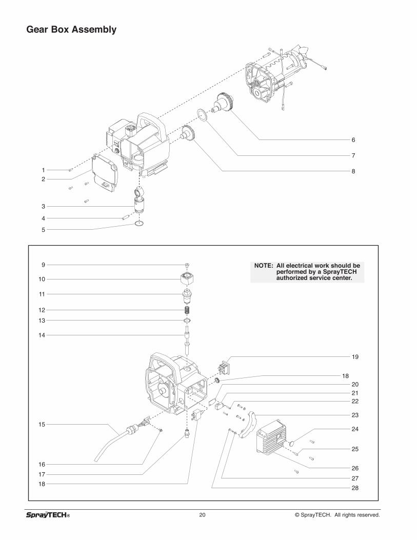
Gear Box Assembly
© SprayTECH. All rights reserved. 21
Item Part # Description Quantity1 0509218 Screw..........................................................42 0551518 Front cover..................................................13 0551541 Slider assembly ..........................................14 0507777 Connecting pin............................................15 0507768 Retaining ring..............................................16 0508572 Crankshaft/gear assembly ..........................17 0508573 Thrust washer .............................................18 0509121 Second stage gear .....................................19 0509219 Screw..........................................................110 0551513 Pressure control knob.................................111 0551522 Knob housing..............................................112 02712 Knob spring.................................................113 9822522 Washer........................................................114 0551521 Plunger .......................................................115 0551516 Power cord assembly (stand) .....................1
0551432 Power cord assembly (low boy and upright cart)
Item Part # Description Quantity16 9800340 Ground screw .............................................117 0551112 Transducer assembly (includes o-ring) ......118 0551515 Circuit breaker ............................................119 9850936 ON/OFF switch ...........................................120 03662 Microswitch insulator ..................................121 0295490 Microswitch .................................................122 9800604 Screw..........................................................223 0295451 Relay, 120V ................................................124 0507751 Port plug .....................................................125 0509218 Screw..........................................................426 0551523 Heat sink assembly
(includes items 24 and 25) .........................127 0551499 Flat washer .................................................328 0551495 Screw..........................................................3
0551520 Mechanical control assembly(includes items 11–14)
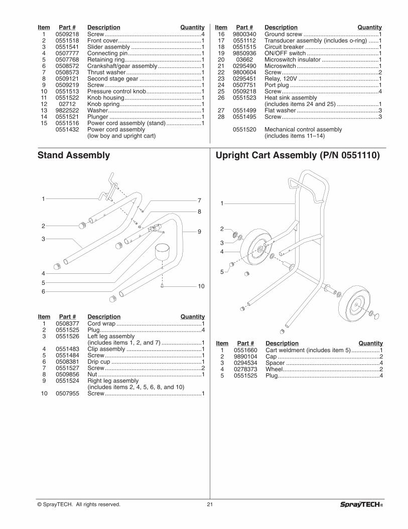
Stand Assembly
Item Part # Description Quantity1 0508377 Cord wrap ...................................................12 0551525 Plug.............................................................43 0551526 Left leg assembly
(includes items 1, 2, and 7) ........................14 0551483 Clip assembly .............................................15 0551484 Screw..........................................................16 0508381 Drip cup ......................................................17 0551527 Screw..........................................................28 0509856 Nut ..............................................................19 0551524 Right leg assembly
(includes items 2, 4, 5, 6, 8, and 10)10 0507955 Screw..........................................................1
2
1
3
5
4
6
7
8
10
9
Upright Cart Assembly (P/N 0551110)
Item Part # Description Quantity1 0551660 Cart weldment (includes item 5).................12 9890104 Cap .............................................................23 0294534 Spacer ........................................................44 0278373 Wheel..........................................................25 0551525 Plug.............................................................4
1
2
3
5
4
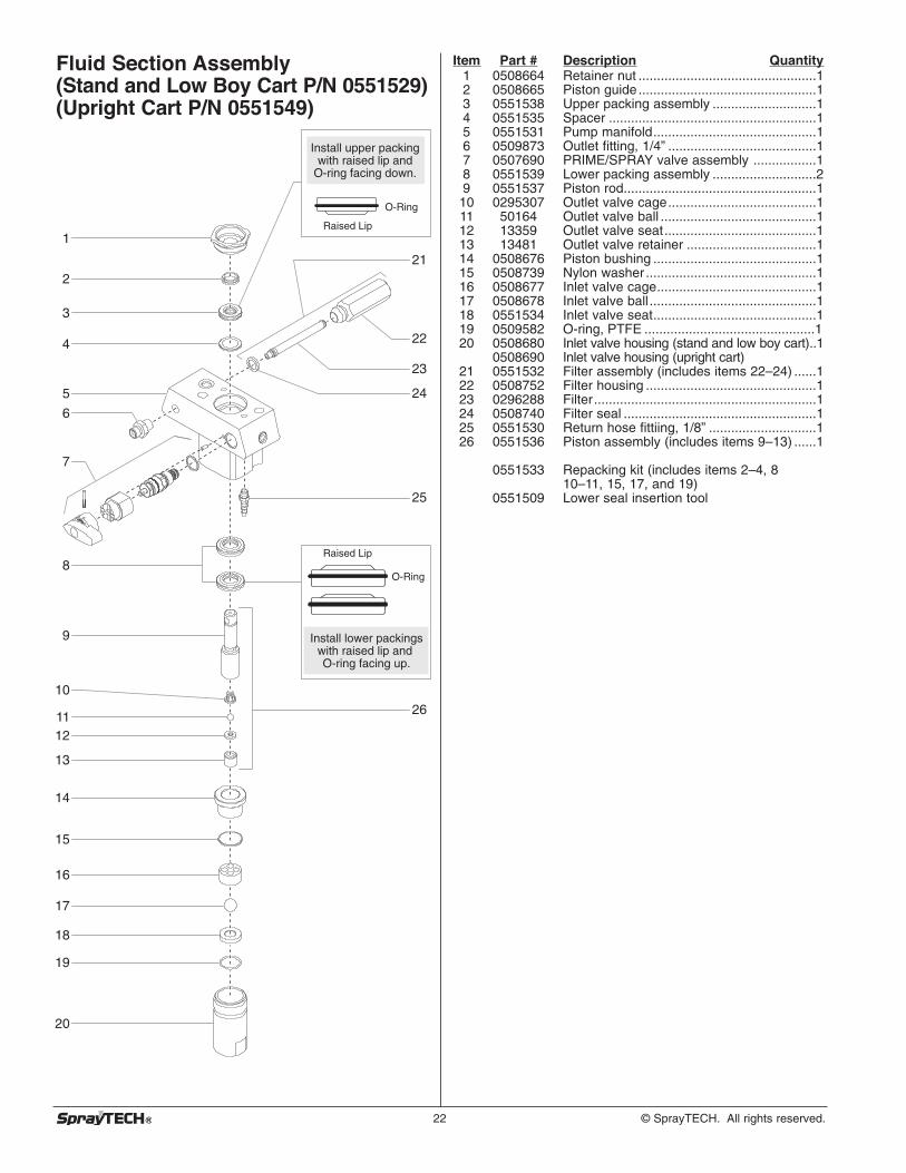
22 © SprayTECH. All rights reserved.
Fluid Section Assembly(Stand and Low Boy Cart P/N 0551529)(Upright Cart P/N 0551549)
1
7
8
9
10
1112
13
14
15
16
17
18
19
20
2
3
4
5
6
22
21
23
24
25
26
Install lower packings with raised lip and O-ring facing up.
O-Ring
Raised Lip
Install upper packing with raised lip and
O-ring facing down.
O-Ring
Raised Lip
Item Part # Description Quantity1 0508664 Retainer nut ................................................12 0508665 Piston guide................................................13 0551538 Upper packing assembly ............................14 0551535 Spacer ........................................................15 0551531 Pump manifold............................................16 0509873 Outlet fitting, 1/4” ........................................17 0507690 PRIME/SPRAY valve assembly .................18 0551539 Lower packing assembly ............................29 0551537 Piston rod....................................................1
10 0295307 Outlet valve cage........................................111 50164 Outlet valve ball ..........................................112 13359 Outlet valve seat.........................................113 13481 Outlet valve retainer ...................................114 0508676 Piston bushing ............................................115 0508739 Nylon washer ..............................................116 0508677 Inlet valve cage...........................................117 0508678 Inlet valve ball .............................................118 0551534 Inlet valve seat............................................119 0509582 O-ring, PTFE ..............................................120 0508680 Inlet valve housing (stand and low boy cart)..1
0508690 Inlet valve housing (upright cart)21 0551532 Filter assembly (includes items 22–24) ......122 0508752 Filter housing ..............................................123 0296288 Filter............................................................124 0508740 Filter seal ....................................................125 0551530 Return hose fittiing, 1/8” .............................126 0551536 Piston assembly (includes items 9–13) ......1
0551533 Repacking kit (includes items 2–4, 810–11, 15, 17, and 19)
0551509 Lower seal insertion tool
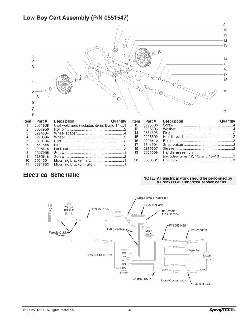
© SprayTECH. All rights reserved. 23
Plu
g Circuit Breaker
Micro- switch
SP1
SP2
SP3
SP4
SP5
Relay
Capacitor
Motor
WHITE
BLACK
BLACK BLACK
REDRED
90º Female Quick Connect
Male/Female Piggyback
Female Quick Connect
P/N 0551496
P/N 0551497
P/N 0507974P/N 0551498
P/N 0508650
P/N 0295418P/N 0507974
P/N 0508644Motor Compartment
Electrical Schematic
Low Boy Cart Assembly (P/N 0551547)91011
1213
14
151617
18
20
19
12
3
4
6
7
8
3
5
Item Part # Description Quantity1 0551608 Cart weldment (includes items 6 and 14)...12 0507956 Roll pin........................................................23 0294534 Wheel spacer..............................................44 0270394 Wheel..........................................................25 9890104 Cap .............................................................26 0551548 Plug.............................................................27 0295615 Lock nut ......................................................28 0507955 Screw..........................................................19 0295618 Screw..........................................................210 0551551 Mounting bracket, left .................................111 0551552 Mounting bracket, right ...............................1
Item Part # Description Quantity12 0295608 Screw..........................................................413 0295606 Washer........................................................414 0551525 Plug.............................................................215 0295609 Handle washer............................................216 0295610 Roll pin........................................................217 9841504 Snap button ................................................218 0295607 Sleeve.........................................................219 0551609 Handle asssembly
(includes items 12, 13, and 15–18 .............120 0508381 Drip cup ......................................................1
NOTE: All electrical work should be performed bya SprayTECH authorized service center.

24 © SprayTECH. All rights reserved.
Limited WarrantySprayTECH, a division of Wagner Spray Tech Corporation ("SprayTECH"), warrants that at the time of delivery to the originalpurchaser for use (“End User”), the equipment covered by this warranty is free from defects in material and workmanship. Withthe exception of any special, limited, or extended warranty published by SprayTECH, SprayTECH ’s obligation under thiswarranty is limited to replacing or repairing without charge those parts which, to SprayTECH ’s reasonable satisfaction, are shownto be defective within twelve (12) months after sale to the End User. This warranty applies only when the unit is installed andoperated in accordance with the recommendations and instructions of SprayTECH.This warranty does not apply in the case of damage or wear caused by abrasion, corrosion or misuse, negligence, accident,faulty installation, substitution of non- SprayTECH component parts, or tampering with the unit in a manner to impair normaloperation.Defective parts are to be returned to an authorized SprayTECH sales/service outlet. All transportation charges, including returnto the factory, if necessary, are to be borne and prepaid by the End User. Repaired or replaced equipment will be returned to theEnd User transportation prepaid.THERE IS NO OTHER EXPRESS WARRANTY. SPRAYTECH HEREBY DISCLAIMS ANY AND ALL IMPLIED WARRANTIESINCLUDING, BUT NOT LIMITED TO, THOSE OF MERCHANTABILITY AND FITNESS FOR A PARTICULAR PURPOSE, TOTHE EXTENT PERMITTED BY LAW. THE DURATION OF ANY IMPLIED WARRANTIES WHICH CANNOT BE DISCLAIMED ISLIMITED TO THE TIME PERIOD SPECIFIED IN THE EXPRESS WARRANTY. IN NO CASE SHALL SPRAYTECH LIABILITYEXCEED THE AMOUNT OF THE PURCHASE PRICE. LIABILITY FOR CONSEQUENTIAL, INCIDENTAL OR SPECIALDAMAGES UNDER ANY AND ALL WARRANTIES IS EXCLUDED TO THE EXTENT PERMITTED BY LAW.SPRAYTECH MAKES NO WARRANTY AND DISCLAIMS ALL IMPLIED WARRANTIES OF MERCHANTABILITY AND FITNESSFOR A PARTICULAR PURPOSE WITH RESPECT TO ACCESSORIES, EQUIPMENT, MATERIALS OR COMPONENTS SOLDBUT NOT MANUFACTURED BY SPRAYTECH. THOSE ITEMS SOLD, BUT NOT MANUFACTURED BY SPRAYTECH (SUCHAS GAS ENGINES, SWITCHES, HOSES, ETC.) ARE SUBJECT TO THE WARRANTY, IF ANY, OF THEIR MANUFACTURER.SPRAYTECH WILL PROVIDE THE PURCHASER WITH REASONABLE ASSISTANCE IN MAKING ANY CLAIM FOR BREACHOF THESE WARRANTIES.
Material Safety Data Sheets (MSDS) are available on SprayTECH’s website or by calling Technical Service.
PatentsThese products are covered by one or more of the following U.S. patents:
6,031,352 5,848,566 5,769,321 5,725,364 5,671,656 5,435,697 5,228,8425,346,037 5,252,210 5,217,238 5,192,425 4,908,538 4,768,929 4,744,571D384,676 6,179,222 5,934,883 4,723,892
SprayTECH1770 Fernbrook LaneMinneapolis, MN 55447
Technical Assistance: 1-800-292-4637Order Entry: 1-800-443-4500
Fax: 1-800-525-9501
www.spraytechinc.com