equ frame method tw slabs prof r bayan salim chapter 5
TRANSCRIPT
5 Equ
ChaSys
IntrThe DmoreThe E By tand
Fig EachThisside For colu
ivalent Frame
apter 5:stems
roductionDDM for TW general met
EFM is base
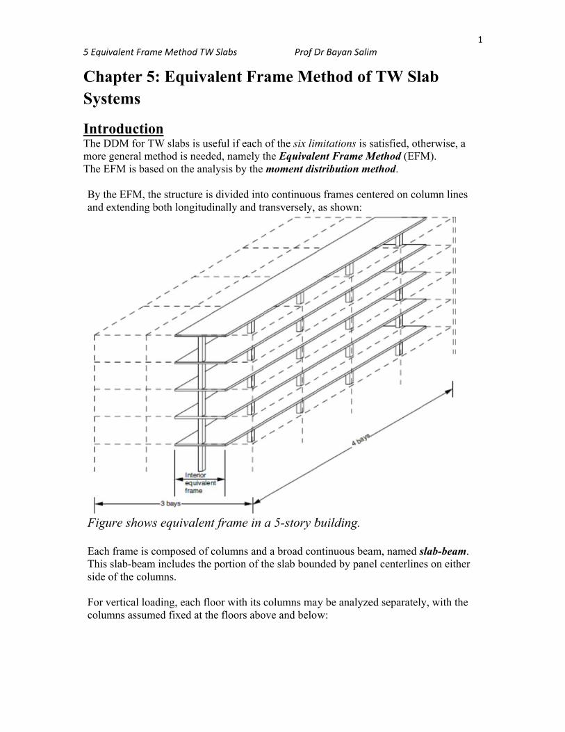
the EFM, theextending bo
ure shows
h frame is cos slab-beam iof the colum
vertical loadumns assume
e Method TW
: Equiva
n W slabs is usthod is needd on the ana
e structure isoth longitud
equivalent
omposed of cincludes the mns.
ding, each floed fixed at th
W Slabs
alent Fr
seful if each ed, namely t
alysis by the
s divided intodinally and tr
t frame in
columns andportion of th
oor with its che floors abo
Prof D
ame Me
of the six limthe Equivalemoment dis
o continuousransversely,
a 5-story b
d a broad conhe slab boun
columns maove and below
Dr Bayan Salim
ethod of
mitations is sent Frame Mstribution m
s frames cenas shown:
building.
ntinuous beanded by pane
ay be analyzew:
m
f TW Sla
satisfied, othMethod (EFMethod.
ntered on col
am, named sel centerline
ed separately
ab
herwise, a M).
lumn lines
slab-beam. es on either
y, with the
1
5 Equ
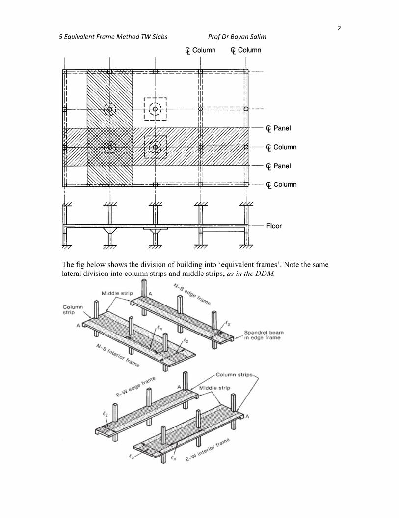
The later
ivalent Frame
fig below shral division i
e Method TW
hows the divinto column
W Slabs
vision of builstrips and m
Prof D
lding into ‘emiddle strips,
Dr Bayan Salim
equivalent fr, as in the DD
m
ames’. NoteDM.
e the same
2
3 5 Equivalent Frame Method TW Slabs Prof Dr Bayan Salim
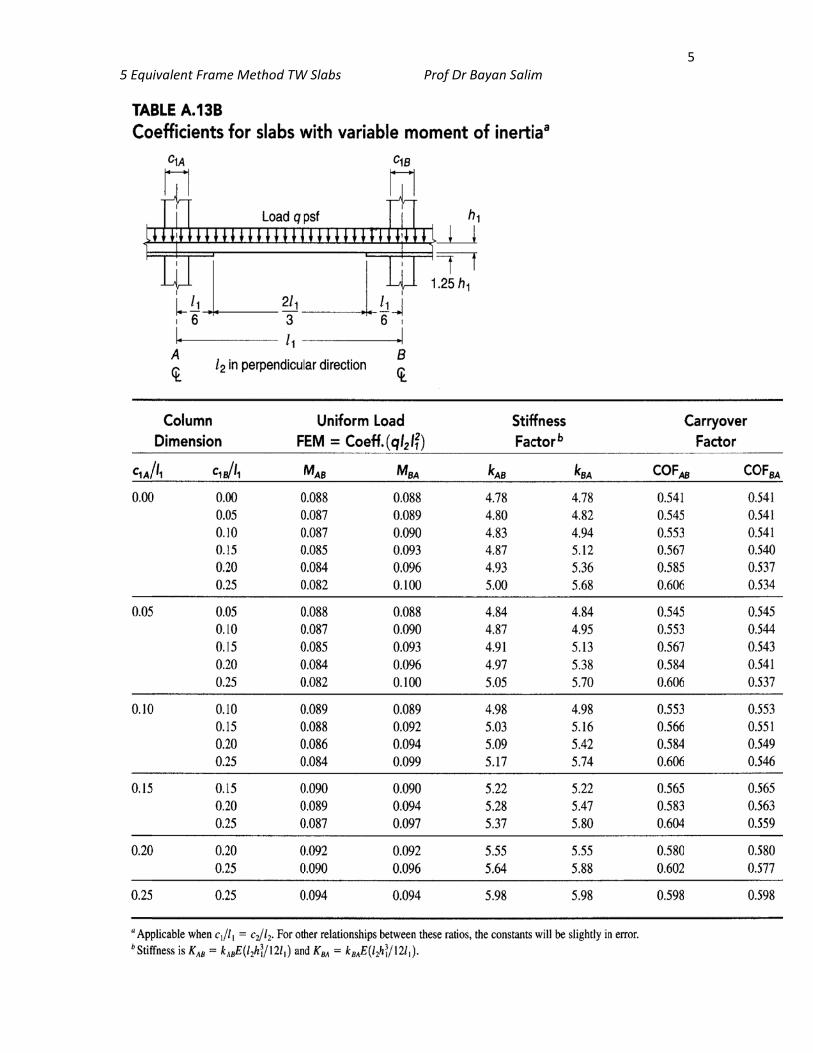
The Slab-beam Stiffnes: Ksb
The slab beam moment of inertia Isb is uniform thru the span but it changes at the support and drop panels if any. According to ACI 8.11.3; Isb,(inside support) = Isb /(1 – c2/l2)
2
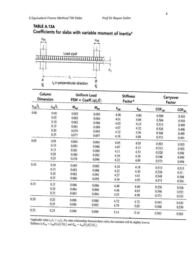
c2 = size of column or capital in direction of l2 l2 = panel width Analysis by the moment distribution method needs stiffness factors k, carry-over factors COF, and fixed-end moment factors M. These are given in Table A13a for slabs w/o drop panels and Table A13b for slabs with drop panels:
Ksb = k (EIsb / l1) Fixed-end Moment = (factorM)(qu l2 l1
2)
5 Equivalent Framee Method TWW Slabs Prof DDr Bayan Salimm 4
5 Equivalent Framee Method TWW Slabs Prof DDr Bayan Salimm 5
5 Equ
TheThe are tcent
The the s
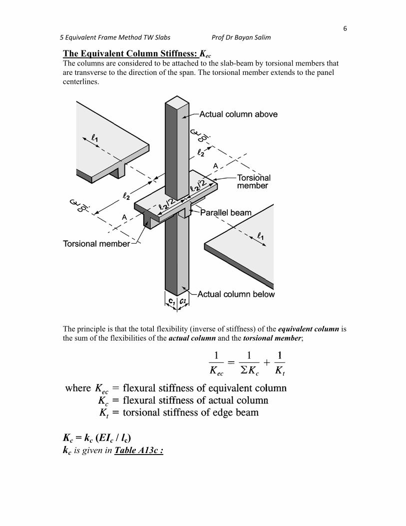
Kc =kc i
ivalent Frame
e Equivalecolumns are
transverse toterlines.
principle is sum of the fl
= kc (EIc is given in
e Method TW
ent Colume consideredo the directio
that the totalexibilities o
/ lc) Table A13
W Slabs
mn Stiffnesd to be attachon of the spa
al flexibility of the actual
3c :
Prof D
ss: Kec hed to the slan. The torsio
(inverse of scolumn and
Dr Bayan Salim
ab-beam by tonal membe
stiffness) of d the torsion
m
torsional mer extends to
the equivalenal member;
embers that the panel
ent column i
6
is
5 Equ
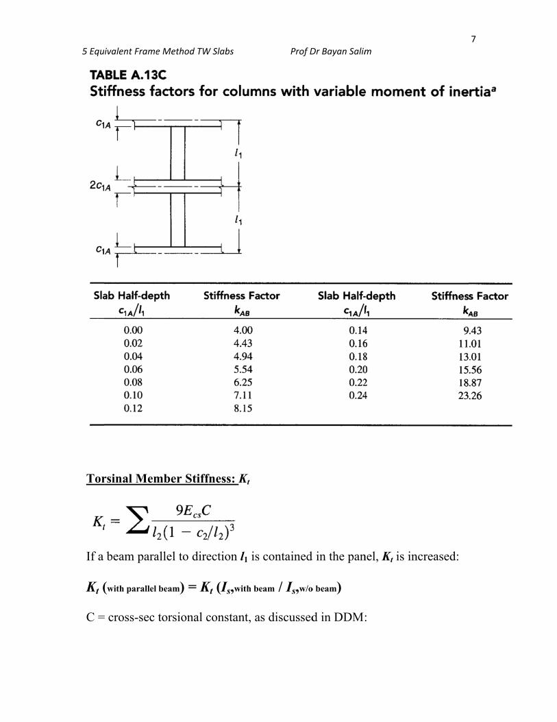
Tor
If a Kt ( C =
ivalent Frame
rsinal Mem
beam para
(with parallel
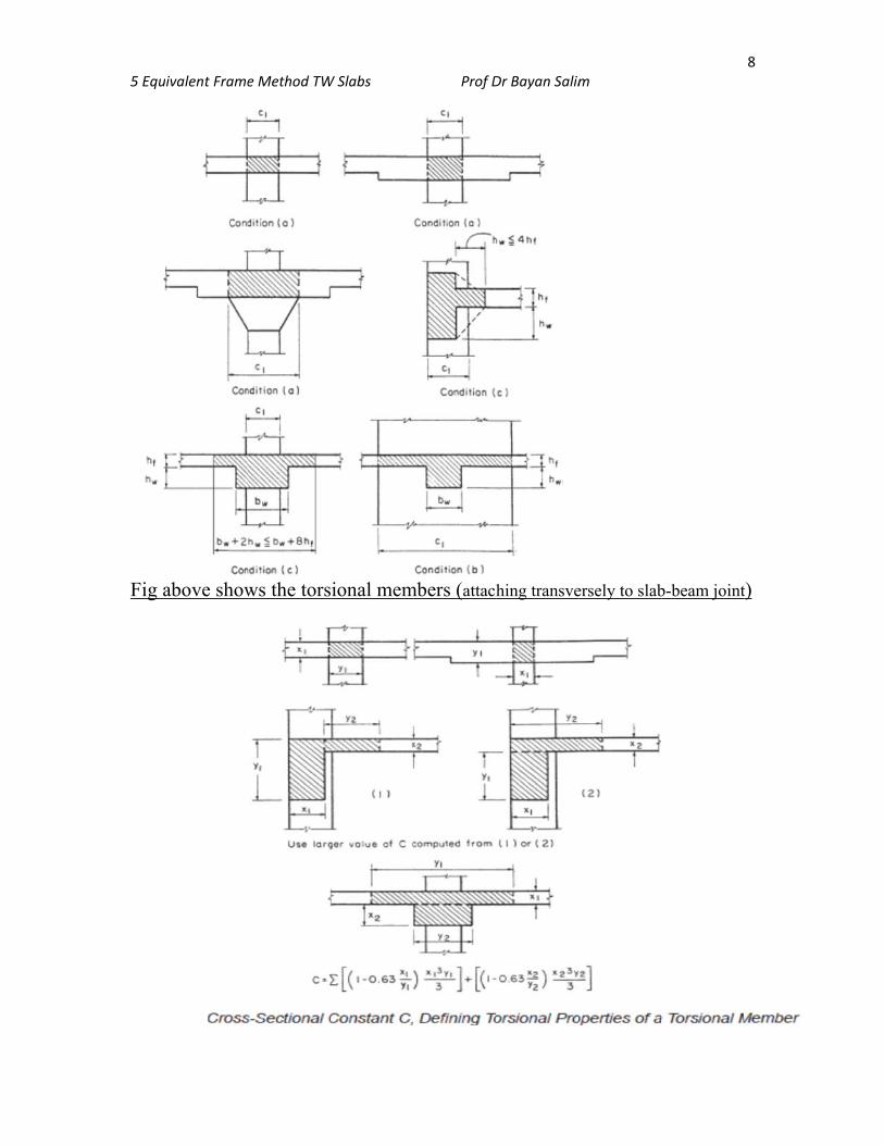
= cross-sec
e Method TW
mber Stiff
allel to dire
beam) = K
torsional c
W Slabs
fness: Kt
ection l1 is
Kt (Is,with be
constant, a
Prof D
contained
eam / Is,w/o
s discussed
Dr Bayan Salim
d in the pan
o beam)
d in DDM
m
nel, Kt is in
:
ncreased:
7
5 Equ
Fig a
ivalent Frame
above show
e Method TW
ws the tors
W Slabs
ional mem
Prof D
mbers (attach
Dr Bayan Salim
hing transve
m
ersely to slabb-beam joint
8
t)
5 Equ
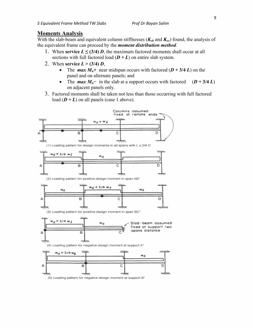
MomWith the eq
1
2
3
ivalent Frame
ments Anathe slab-bea
quivalent fra. When ser
sections w2. When ser
Thpa
Thon
. Factored mload (D +
e Method TW
alysis am and equivame can procrvice L ≤ (3/with full factrvice L > (3/he max Mu+anel and on ahe max Mu−n adjacent pamoments sh
+ L) on all pa
W Slabs
valent columceed by the m/4) D, the matored load (D/4) D, + near midspalternate pan− in the slabanels only. all be taken
anels (case 1
Prof D
mn stiffnessemoment distaximum factD + L) on en
pan occurs wnels; and b at a suppor
not less than above).
Dr Bayan Salim
es (Ksb and Ktribution metored momen
ntire slab sys
with factored
rt occurs wit
n those occu
m
Kec) found, thethod. nts shall occstem.
d (D + 3/4 L
th factored
urring with fu
he analysis o
cur at all
L) on the
(D + 3/4 L
ull factored
9
of
L)
5 Equ
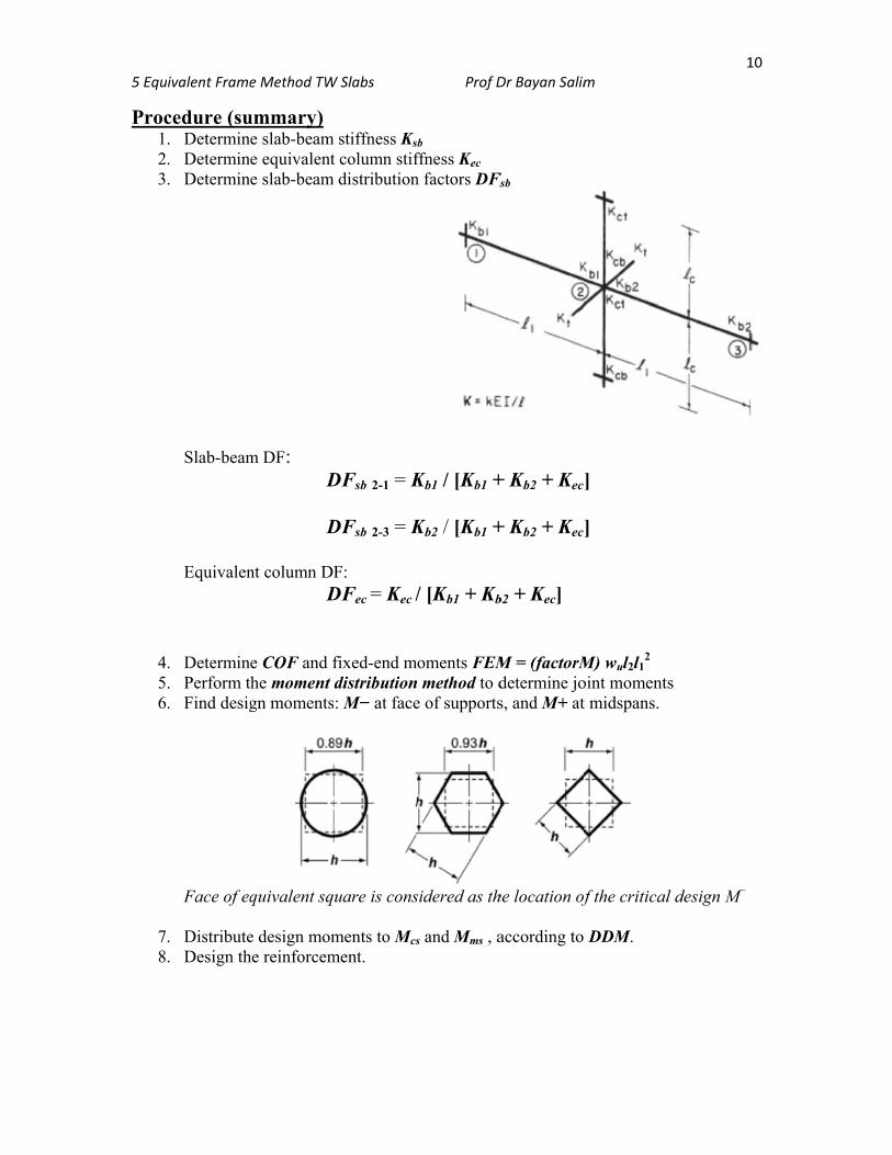
Proc123
456
78
ivalent Frame
cedure (su. Determin. Determin. Determin
Slab-beam Equivalen
. Determin
. Perform t
. Find desig
Face of eq
. Distribute
. Design th
e Method TW
ummary) e slab-beame equivalente slab-beam
m DF: D
D
nt column DF D
e COF and fhe moment gn moments
quivalent sq
e design momhe reinforcem
W Slabs
m stiffness Ks
t column stifm distribution
DFsb 2-1 = K
DFsb 2-3 = K
F: DFec = Kec /
fixed-end mdistribution: M− at face
uare is cons
ments to Mcs
ment.
Prof D
b ffness Kec n factors DFs
Kb1 / [Kb1 +
Kb2 / [Kb1 +
/ [Kb1 + Kb
oments FEM method to d
e of supports
sidered as th
s and Mms , a
Dr Bayan Salim
Fsb
+ Kb2 + Kec
+ Kb2 + Kec
b2 + Kec]
M = (factorMdetermine jos, and M+ at
he location of
according to
m
]
]
M) wul2l12
oint momentt midspans.
f the critical
DDM.
1
s
l design M−
10
5 Equ
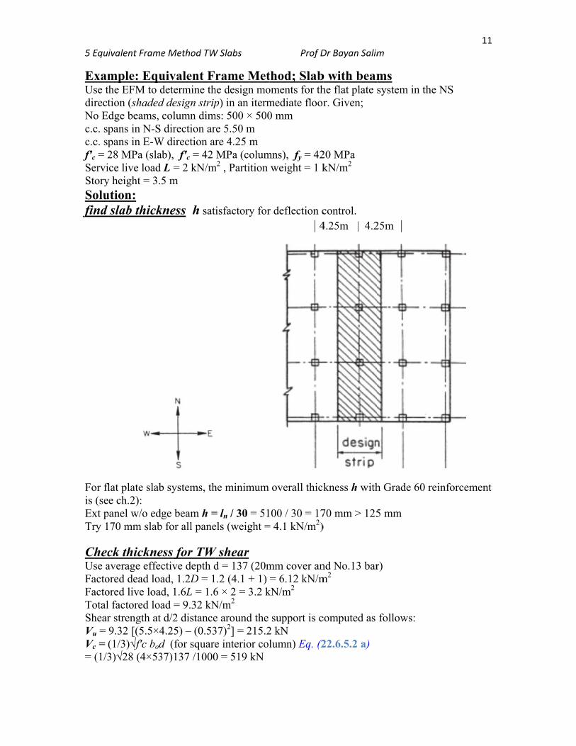
ExamUse tdirectNo Ec.c. sc.c. sf′c = 2ServiStorySolufind
For flis (seExt pTry 1
ChecUse aFactoFactoTotalShearVu = Vc = = (1/3
ivalent Frame
mple: Equthe EFM to dtion (shaded
Edge beams, pans in N-S pans in E-W28 MPa (slaice live load y height = 3.5ution:
slab thick
flat plate slabee ch.2): panel w/o edg170 mm slab
ck thickneaverage effecored dead loaored live loadl factored loar strength at 9.32 [(5.5×4(1/3)√f′c bod3)√28 (4×53
e Method TW
uivalent Fdetermine thd design stripcolumn dimdirection ar
W direction arab), f′c = 42
L = 2 kN/m5 m
kness h sati
b systems, th
ge beam h =b for all pane
ess for TW ctive depth dad, 1.2D = 1d, 1.6L = 1.6ad = 9.32 kNd/2 distance
4.25) – (0.53d (for square37)137 /1000
W Slabs
rame Methe design mop) in an iterm
ms: 500 × 500re 5.50 m re 4.25 m MPa (colum
m2 , Partition
isfactory for
he minimum
= ln / 30 = 51els (weight =
W shear d = 137 (20m.2 (4.1 + 1)
6 × 2 = 3.2 kN/m2
e around the 37)2] = 215.2e interior col0 = 519 kN
Prof D
thod; Slaboments for thmediate floor0 mm
mns), fy = 42weight = 1 k
r deflection c | 4
overall thick
100 / 30 = 17= 4.1 kN/m2)
mm cover an= 6.12 kN/m
kN/m2
support is c2 kN lumn) Eq. (2
Dr Bayan Salim
b with beamhe flat plate sr. Given;
20 MPa kN/m2
control. 4.25m | 4.2
kness h with
70 mm > 125)
nd No.13 barm2
computed as
22.6.5.2 a)
m
ms system in th
25m |
h Grade 60 r
5 mm
r)
follows:
1
he NS
reinforcemen
11
nt
5 Equ
φVc =after
FlexKsb =Tablec1A/l1
FromKsb 1Ksb 2 FlexKc = TableFromKc, be Tors
| 5 C = (Kt = 9 Equ
1/ Kec
on eaKec = SlabAt exDF =At inDF =
ivalent Frame
= 0.75 ×519 finding mom
xural stiffn= k EIsb / l1 e A13a; ext j1 = 500 / 550
m Table: MAB
-2 = Ksb 2-1 -3 = Ksb 3-2
xural stiffnk EIc / lc e A13c; lc = l
m Table: kAB elow = Kc, ab
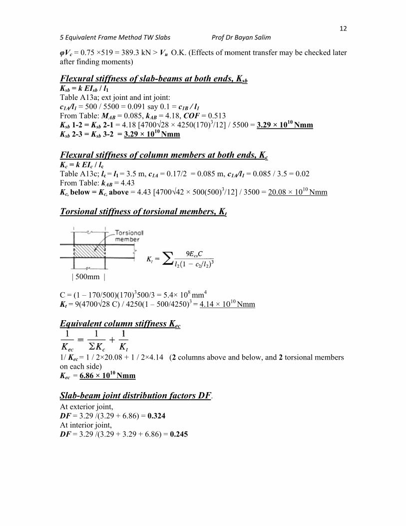
sional stiff
500mm |
(1 – 170/5009(4700√28 C
ivalent col
c = 1 / 2×20.ach side) = 6.86 × 10¹⁰
b-beam joinxterior joint, = 3.29 /(3.29terior joint,
= 3.29 /(3.29
e Method TW
= 389.3 kN ments)
ness of slab
joint and int 00 = 0.091 saB = 0.085, kA
= 4.18 [470 = 3.29 × 10
ness of colu
l1 = 3.5 m, c= 4.43 bove = 4.43
fness of tor
0)(170)3500/3C) / 4250(1 –
lumn stiffn
08 + 1 / 2×4
0 Nmm
nt distribu
+ 6.86) = 0.
+ 3.29 + 6.8
W Slabs
> Vu O.K. (
b-beams at
joint: ay 0.1 = c1B /AB = 4.18, CO00√28 × 4250010 Nmm
umn memb
1A = 0.17/2
[4700√42 ×
rsional me
3 = 5.4× 10⁸
– 500/4250)3
ness Kec
4.14 (2 colu
tion factor
.324
86) = 0.245
Prof D
(Effects of m
t both ends
/ l1 OF = 0.5130(170)3/12]
bers at bot
= 0.085 m, c
500(500)3/1
embers, Kt
8 mm4 3 = 4.14 × 10
umns above
rs DF.
Dr Bayan Salim
moment trans
ds, Ksb
/ 5500 = 3.2
th ends, Kc
c1A/l1 = 0.08
12] / 3500 =
010 Nmm
and below, a
m
sfer may be
29 × 1010 Nm
Kc
85 / 3.5 = 0.0
= 20.08 × 101
and 2 torsion
1
checked late
mm
02
10 Nmm
nal members
12
er
s
5 Equ
FramL / DsectioFactoFactoFactoFactoFEM= 0.0 MomCoun
Jo
MemD
COFEMDM CO DM CO DM Σ M
MCL
Mid sMCL wherPosit+MCL
Posit+MCL
SheaV (supV (lef V (rig ShearV (lef
ivalent Frame
me AnalysD = 2 / 5.1 = ons with fullored load andored dead loaored live loadored load qu =
M’s for slab-b85 (9.32) (4
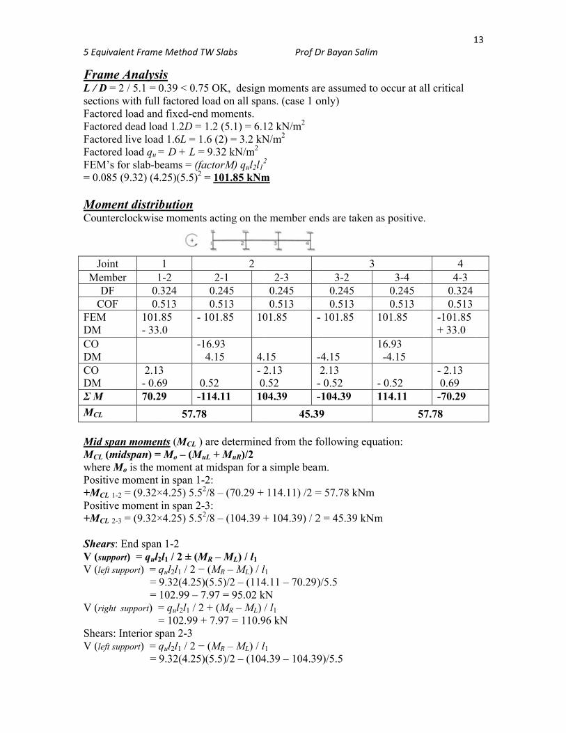
ment distribnterclockwis
oint mber 1
DF 0.OF 0.
M 101- 33
2.1- 0.670.2
span momen(midspan) =e Mo is the mive moment L 1-2 = (9.32×ive moment L 2-3 = (9.32×
ars: End spanupport) = qul2
ft support) = = =
ght support) = =
rs: Interior sft support) = =
e Method TW
sis 0.39 < 0.75 l factored load fixed-end mad 1.2D = 1.d 1.6L = 1.6= D + L = 9
beams = (fac.25)(5.5)2 =
bution e moments a
1
1-2 .324 0.513 0.85 .0
- 10 -16 4.
3 69
0.5
29 -11
57.78
nts (MCL ) ar= Mo – (MuL moment at min span 1-2:
×4.25) 5.52/8in span 2-3:
×4.25) 5.52/8
n 1-2 2l1 / 2 ± (MR
qul2l1 / 2 − (M9.32(4.25)(5102.99 – 7.9= qul2l1 / 2 += 102.99 + 7pan 2-3 qul2l1 / 2 − (M9.32(4.25)(5
W Slabs
OK, designad on all spamoments. 2 (5.1) = 6.1 (2) = 3.2 kN
9.32 kN/m2 torM) qul2l1
2
101.85 kNm
acting on the
2 2-1
0.245 0.513 01.85 10
.93 .15
4.
52 - 2 0
4.11 10
re determine+ MuR)/2
midspan for a: 8 – (70.29 + : 8 – (104.39 +
R – ML) / l1
MR – ML) / l5.5)/2 – (11497 = 95.02 k+ (MR – ML) /7.97 = 110.9
MR – ML) / l5.5)/2 – (104
Prof D
n moments arans. (case 1 o
12 kN/m2 N/m2
2 m
e member en
2-3 0.245 0.513
01.85 -
15 -2.13 .52 -
04.39 -
45.3
ed from the f
a simple bea
114.11) /2 =
+ 104.39) / 2
l1 4.11 – 70.29)kN / l1
96 kN
l1 4.39 – 104.39
Dr Bayan Salim
re assumed tonly)
nds are taken
3
3-2 0.245 0.513
- 101.85
-4.15 2.13
- 0.52 -104.39
39
following eq
am.
= 57.78 kNm
2 = 45.39 kN
)/5.5
9)/5.5
m
to occur at a
n as positive
3 3-4
0.245 0.513
101.85
16.93 -4.15 - 0.52 114.11
5
quation:
m
Nm
1
all critical
.
4 4-3
0.3240.513
-101.85 + 33.0
- 2.13 0.69 -70.29
7.78
13
14 5 Equivalent Frame Method TW Slabs Prof Dr Bayan Salim
= 102.99 – 0 = 102.99 kN V (right support) = qul2l1 / 2 + (MR – ML) / l1 = 102.99 + 0 = 102.99 kN Design –ve Moment = Joint moment – area of shear diagram bet support CL and face At joint 1, Design M− = 70.29 – (95.02 kN × 0.25 m) = 46.54 kNm At joint 2 left, Design M− = 114.11 – (110.96 kN × 0.25 m) = 86.37 kNm At joint 2 right, Design M− = 104.39 – (102.99 kN × 0.25 m) = 78.64 kNm At joint 3 left, Design M− = 78.64 kNm
Moments at critical sections (summary): Interior spans Interior M− = 78.64 kN, M+ = 45.39 kNm End span Exterior M− = 46.54 kNm, M+ = 57.78 kNm, Interior M− = 86.37 kNm
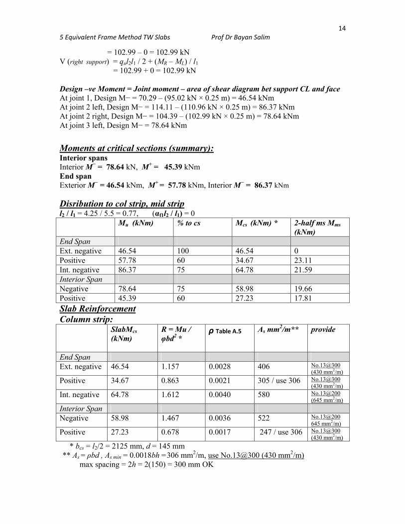
Disribution to col strip, mid strip l2 / l1 = 4.25 / 5.5 = 0.77, (αf1l2 / l1) = 0 Mu (kNm) % to cs Mcs (kNm) * 2-half ms Mms
(kNm) End Span Ext. negative 46.54 100 46.54 0 Positive 57.78 60 34.67 23.11 Int. negative 86.37 75 64.78 21.59 Interior Span Negative 78.64 75 58.98 19.66 Positive 45.39 60 27.23 17.81 Slab Reinforcement Column strip: SlabMcs
(kNm)
R = Mu / φbd2 *
ρ Table A.5 As mm2/m** provide
End Span Ext. negative 46.54 1.157 0.0028 406 No.13@300
(430 mm2/m)
Positive 34.67 0.863 0.0021 305 / use 306 No.13@300 (430 mm2/m)
Int. negative 64.78 1.612 0.0040 580 No.13@200 (645 mm2/m)
Interior Span Negative 58.98 1.467 0.0036 522 No.13@200
645 mm2/m)
Positive 27.23 0.678 0.0017 247 / use 306 No.13@300 (430 mm2/m)
* bcs = l2/2 = 2125 mm, d = 145 mm ** As = ρbd , As min = 0.0018bh =306 mm2/m, use No.13@300 (430 mm2/m)
max spacing = 2h = 2(150) = 300 mm OK
5 Equ
Midd
End SExt. n
PositInt. nInteriNegaPosit * b
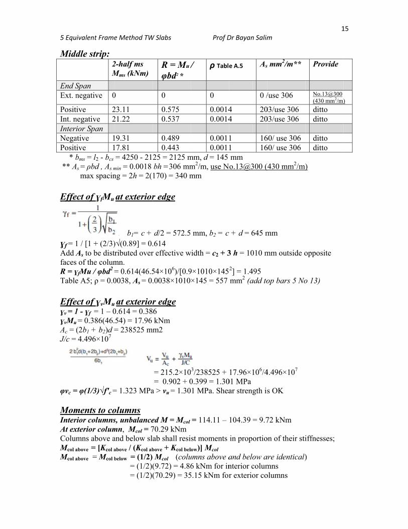
** A Effe
ɣf = 1Add AfacesR = ɣTable Effeɣv = 1ɣvMu
Ac = (J/c =
φvc = MomInterAt exColumMcol a
Mcol a
ivalent Frame
dle strip: 2M
Span negative 0
ive 2negative 2ior Span
ative 1ive 1bms = l2 - bcs
As = ρbd , As m
max spacin
ect of ɣfMu
1 / [1 + (2/3)As to be dist of the columɣfMu / φbd2 =e A5; ρ = 0.0
ect of ɣvMu1 - ɣf = 1 – 0 = 0.386(46.(2b1 + b2)d =4.496×107
= φ(1/3)√f′c =
ments to corior columnsxterior colummns above aabove = [Kcol a
above = Mcol b
e Method TW
2-half ms Mms (kNm)
0
23.11 21.22
19.31 17.81 = 4250 - 21
min = 0.0018 ng = 2h = 2(
at exterior
b1= c + )√(0.89] = 0.tributed overmn. = 0.614(46.50038, As = 0.
at exterior0.614 = 0.3854) = 17.96 = 238525 m
= 1.323 MPa
olumns s, unbalancemn, Mcol = 7and below slabove / (Kcol ab
below = (1/2) = (1/2)( = (1/2)(
W Slabs
R = Mu /φbd2 *
0
0.575 0.537 0.489 0.443
25 = 2125 mbh =306 mm170) = 340 m
r edge
d/2 = 572.5.614 r effective w
54×106)/[0.9.0038×1010
r edge 6 kNm m2
= 215.2×10= 0.902 + 0
a > vu = 1.30
ed M = Mcol
70.29 kNm ab shall resibove + Kcol bel
Mcol (colu(9.72) = 4.86(70.29) = 35
Prof D
/ ρ Tabl
0
0.00140.0014 0.00110.0011
mm, d = 145m2/m, use Nmm
mm, b2 = c
width = c2 + 3
9×1010×145×145 = 557
3/238525 +
0.399 = 1.301 MPa. Shea
= 114.11 –
st moments ow)] Mcol
umns above a6 kNm for in
5.15 kNm for
Dr Bayan Salim
e A.5 As
0 /
4 204 20
1 161 16mm
No.13@300 (
c + d = 645 m
3 h = 1010 m
2] = 1.495 mm2 (add to
17.96×10⁶/401 MPa ar strength is
104.39 = 9.7
in proportio
and below anterior columr exterior co
m
s mm2/m**
/use 306
03/use 306 03/use 306
60/ use 306 60/ use 306
(430 mm2/m)
mm
mm outside o
op bars 5 No
4.496×10⁷
s OK
72 kNm
on of their sti
are identical)mns olumns
1
Provide
No.13@300 (430 mm2/m)
ditto ditto ditto ditto
)
opposite
o 13)
iffnesses;
)
15
)
5 Equ
HW:Use tNS dEdge InterioColumSlab tc.c. spc.c. spf′c = 2Servic
ivalent Frame
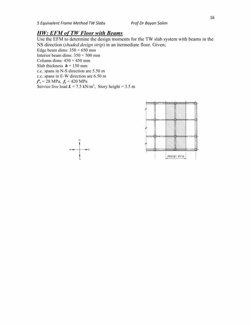
W: EFM of the EFM to direction (shabeam dims: 3or beam dimsmn dims: 450thickness h =pans in N-S dpans in E-W d28 MPa, fy = ce live load L
e Method TW
TW Floor determine thaded design 350 × 650 mms: 350 × 500 m × 450 mm
= 150 mm direction are 5direction are 6420 MPa
L = 7.5 kN/m2
W Slabs
with Beamhe design mostrip) in an i
m mm
5.50 m 6.50 m
2, Story heigh
Prof D
ms oments for thitermediate f
ht = 3.5 m
Dr Bayan Salim
he TW slab sfloor. Given
m
system with n;
1
beams in th
16
e