equipment guide - cochlear implant help · pdf filetable of contents i introduction if...
TRANSCRIPT

Equipment Guide
OPUS 2 Processor

TABLE OF CONTENTS
iINTrOdUCTION
If you’re working with a child who listens with a MEd-EL hearing implant, you’ll soon want assistance in how to handle the equipment, how to verify that the device is working properly, and what to do if the system isn’t working properly..
This guide is designed to help you become confident in handling and assembling
the parts of the OPUS 2 audio processor, understanding all of the available
wearing options, and objectively verifying that the device is working properly.
It will provide step-by-step instructions to help identify and solve any problems
that may arise, and will assist you in understanding how to care for the
system properly.
The OPUS 2 processor offers a number of innovative features. While the
internal electronics are identical to those found in an OPUS 1 processor,
OPUS 2 varies quite a bit from the OPUS 1 and TEMPO+ processors. OPUS 1
and OPUS 2 contain a microchip with the capability to implement newer sound
coding technology (though this new technology may or may not be activated
for a particular child). OPUS 2 also offers a new curved look with no buttons,
switches or knobs. Using the new FineTuner remote control, OPUS 2 processor
settings are easily changed without removing the child’s equipment.
Although the audiologist or the child’s implant center typically handles advanced
troubleshooting, many classroom teachers and therapists find that minor
problems can be quickly and easily managed without disrupting the day’s learning
plan if they are comfortable troubleshooting and handling the equipment. Please
keep this guide in a handy place, and refer to it whenever problems may arise.
.
Equipment Guide: OPUS 2 Audio Processor, Version 1.0. ©2009 MEd-EL COrPOrATION, NA. All rights reserved.
1 Getting to know the OPUS 2 processor ........................2
Parts of the system ..................................................................3
Wearing options.......................................................................11
BabyBTE™ (also called the ‘activity pack’)............. 14
Children’s battery pack ....................................................... 15
Standard battery pack ......................................................... 16
Special considerations for small children ................. 17
remote (rechargeable) battery pack ......................... 18
daCapo rechargeable Battery System .................... 19
2 Getting to know the FineTuner™ remote control .................................................20
Using the FineTuner .............................................................. 21
How to configure the FineTuner .................................. 21
Navigating the FineTuner keyboard ............................22
FineTuner keyboard lock feature ..................................23
Indicator light signals .............................................................24
Changing battery on FineTuner .....................................25
3 Is it working? A troubleshooting primer ......................26
daily listening checks ............................................................26
Troubleshooting features ................................................... 31
A step-by-step troubleshooting guide ......................34
Keeping spare equipment on hand .............................37
What to do if you don’t feel comfortable with the child’s equipment ...............................................38
A word about warranties..................................................38
4 Caring for the system .................................................................40
Moisture .......................................................................................40
Electrostatic discharge ......................................................... 41
Sports ............................................................................................43
Metal detectors .......................................................................43
5 Connecting to Accessory Devices ....................................44
When to use accessory devices such as FM systems ...............................................................46
Mixing options ..........................................................................47
Step by step connection guide ......................................48
6 Glossary of terms related to MEd-EL cochlear implant systems ........................................50
7 MED-EL Milestones ...................................................................... 61
This Guide deals with the OPUS 2 processors.
If you are working with a OPUS 1 or TEMPO+ processor (pictured above), please refer to the Equipment Guide for TEMPO+ and OPUS 1.
NOTE:

3E Q U I P M E N T G U I d E : O P U S 2 P r O C E S S O r 2
1
Control unit
The control unit is just like a tiny computer. Inside, an electronic
chip controls the entire system. It can hold several different
programs (also called ‘maps’), which contain the specific hearing
settings for each child. Features of the control unit include:
Microphone port :: This tiny opening is where sound enters the processor. The microphone is most sensitive to sounds coming from the front, although it is able to pick up sounds from a wide area.
Locking earhook (optional) :: The OPUS 2 processor fea-tures a new earhook that can be secured to the control unit with a small pin to prevent young children from removing the earhook..
Microphone cover :: This small cover is used with the BabyBTETM and ActiveWear configurations. It replaces the earhook for wearing options that are not worn at the ear and serves to protect the microphone.
LED indicator :: This small red light indicates a variety of status and error conditions. It should illuminate when the processor is first turned on and will indicate which position is currently active (with 1, 2, 3 or 4 quick blinks). If it begins flashing during normal use, please refer to the table on page 31 for additional details.
Integrated telecoil :: The telecoil is located in the OPUS 2 control unit and requires no additional parts or cables. Select telecoil settings using the FineTuner remote control to reduce background noise with hearing aid com-patible telephones and induction loop systems.
IRIS safety feature :: The Individual recognition of the Implant System (IrIS) is compatible with PULSArCI100 and SONATATI100 cochlear implants. This safety feature prevents unwanted stimulation to the child if the wrong processor is placed on the head. If an OPUS 1 or OPUS 2 processor doesn’t transmit the correct internal serial number, then the implant will not stimulate. This is especially useful for bilaterally implanted children.
GETTING TO KNOW THE OPUS 2 PrOCESSOr
P A r T S O F T H E S y S T E M
The MEd-EL OPUS 2 processor consists of five main parts: a control unit, a
battery pack, a coil, a coil cable and an earhook or other connecting piece.
The system is modular, so the parts can be combined into different wearing
configurations from day to day, depending on the needs of each child. In addition,
each child receives a patient kit that contains a variety of accessories. Each
wearing option will have the following parts:
1
Integrated telecoil
Microphone port
LEd indicator
Locking earhook
NOTE: Because the audio processor settings are specific to one child only, never switch processors between two different implant users or between ears for a bilateral user. No two ears have the same program settings! The use of a processor belonging to another user could result in overstimulation.
control unit
earhook
battery pack
coil
coil cable
connecting piece
54 E Q U I P M E N T G U I d E : O P U S 2 P r O C E S S O r
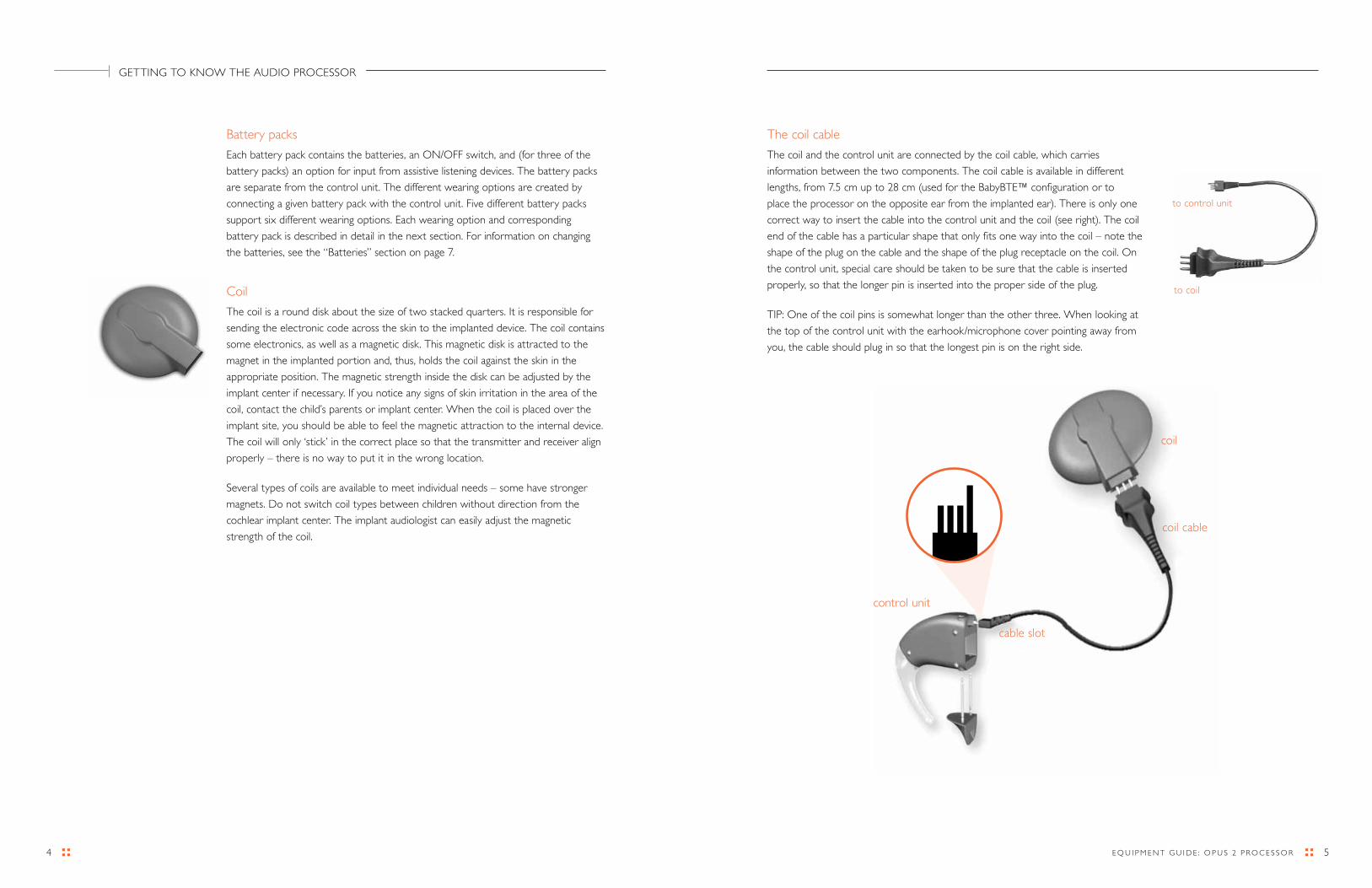
The coil cable
The coil and the control unit are connected by the coil cable, which carries
information between the two components. The coil cable is available in different
lengths, from 7.5 cm up to 28 cm (used for the BabyBTE™ configuration or to
place the processor on the opposite ear from the implanted ear). There is only one
correct way to insert the cable into the control unit and the coil (see right). The coil
end of the cable has a particular shape that only fits one way into the coil – note the
shape of the plug on the cable and the shape of the plug receptacle on the coil. On
the control unit, special care should be taken to be sure that the cable is inserted
properly, so that the longer pin is inserted into the proper side of the plug.
TIP: One of the coil pins is somewhat longer than the other three. When looking at
the top of the control unit with the earhook/microphone cover pointing away from
you, the cable should plug in so that the longest pin is on the right side.
Battery packs
Each battery pack contains the batteries, an ON/OFF switch, and (for three of the
battery packs) an option for input from assistive listening devices. The battery packs
are separate from the control unit. The different wearing options are created by
connecting a given battery pack with the control unit. Five different battery packs
support six different wearing options. Each wearing option and corresponding
battery pack is described in detail in the next section. For information on changing
the batteries, see the “Batteries” section on page 7.
Coil
The coil is a round disk about the size of two stacked quarters. It is responsible for
sending the electronic code across the skin to the implanted device. The coil contains
some electronics, as well as a magnetic disk. This magnetic disk is attracted to the
magnet in the implanted portion and, thus, holds the coil against the skin in the
appropriate position. The magnetic strength inside the disk can be adjusted by the
implant center if necessary. If you notice any signs of skin irritation in the area of the
coil, contact the child’s parents or implant center. When the coil is placed over the
implant site, you should be able to feel the magnetic attraction to the internal device.
The coil will only ‘stick’ in the correct place so that the transmitter and receiver align
properly – there is no way to put it in the wrong location.
Several types of coils are available to meet individual needs – some have stronger
magnets. do not switch coil types between children without direction from the
cochlear implant center. The implant audiologist can easily adjust the magnetic
strength of the coil.
to coil
to control unit
GETTING TO KNOW THE AUdIO PrOCESSOr
control unit
cable slot
coil cable
coil
76 E Q U I P M E N T G U I d E : O P U S 2 P r O C E S S O r
Fixation bar (optional)
For some wearing options, an additional fixation bar or fixation clip is used to attach
a part of the processor to the child’s clothing. Two of the battery packs (straight and
children’s battery packs) have two tiny threaded sleeves on the side of the battery
pack, near the labeling. The fixation bar or fixation clip can be attached to these
battery packs using a small screwdriver.
ON/OFF switch
The power switch is located in the following places:
Standard, FM and DaCapo battery packs: The battery pack
lock functions as the on/off switch. When the battery pack lock
is in the down position (closed), the processor is on. When
the battery pack lock is up (open), the processor is off.
Straight and children’s battery packs: At the tip of the
battery pack, next to the latch that opens the battery door.
It is labeled “I” for ON and “O” for OFF. Keep in mind
that the children’s battery pack is attached to the end of
its own cable.
Remote battery pack: On the base of the battery pack labeled “ON/OFF.”
Battery pack covers
All battery pack options have a cover over the battery compartment, and some are
designed to discourage children from tampering with the batteries. To open the
battery compartment:
Standard, FM and DaCapo battery packs:
The battery pack cover on the standard and daCapo battery packs is built like
a sleeve. The FM battery pack cover also includes input for assistive listening
devices. The battery pack lock functions as the on/off switch. Flip the battery
pack lock up (this turns the processor off), and slide the entire battery pack
cover off the battery pack.
NOTE: Be sure that the battery pack cover is inserted correctly. (See image at right.)
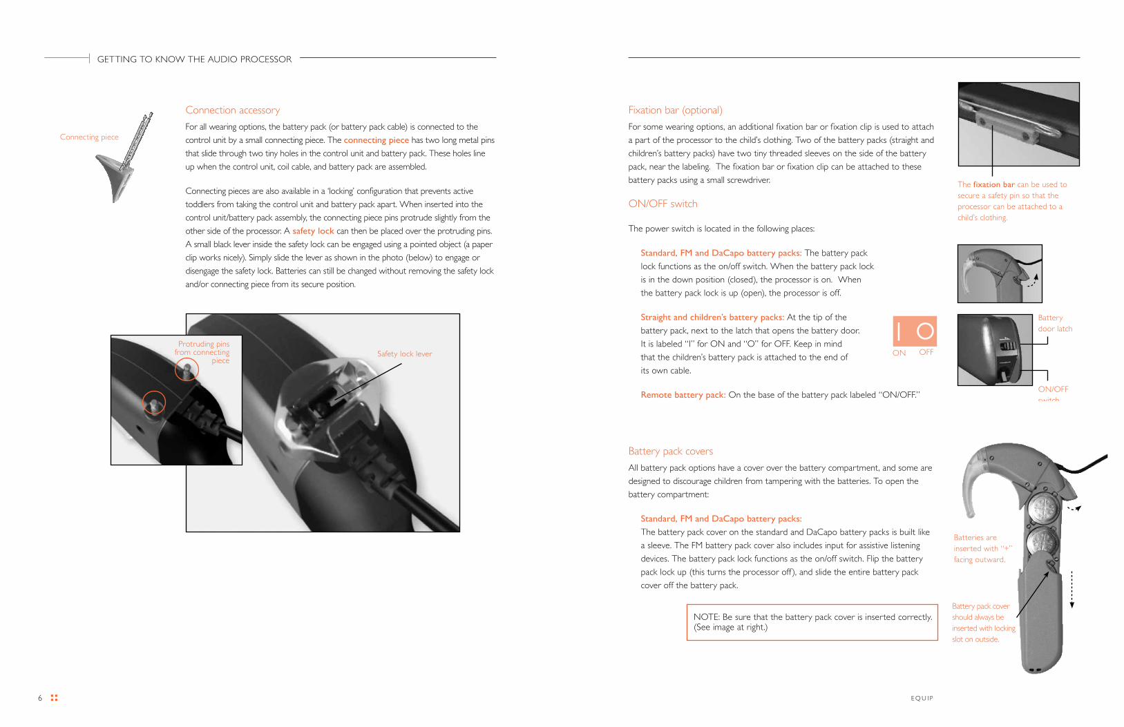
Connection accessory
For all wearing options, the battery pack (or battery pack cable) is connected to the
control unit by a small connecting piece. The connecting piece has two long metal pins
that slide through two tiny holes in the control unit and battery pack. These holes line
up when the control unit, coil cable, and battery pack are assembled.
Connecting pieces are also available in a ‘locking’ configuration that prevents active
toddlers from taking the control unit and battery pack apart. When inserted into the
control unit/battery pack assembly, the connecting piece pins protrude slightly from the
other side of the processor. A safety lock can then be placed over the protruding pins.
A small black lever inside the safety lock can be engaged using a pointed object (a paper
clip works nicely). Simply slide the lever as shown in the photo (below) to engage or
disengage the safety lock. Batteries can still be changed without removing the safety lock
and/or connecting piece from its secure position.
The fixation bar can be used to secure a safety pin so that the processor can be attached to a child’s clothing.
Connecting piece
Battery door latch
ON/OFF switch
GETTING TO KNOW THE AUdIO PrOCESSOr
ON OFFSafety lock leverProtruding pins
from connecting piece
Batteries are inserted with “+” facing outward.
Battery pack cover should always be inserted with locking slot on outside.
98 E Q U I P M E N T G U I d E : O P U S 2 P r O C E S S O r
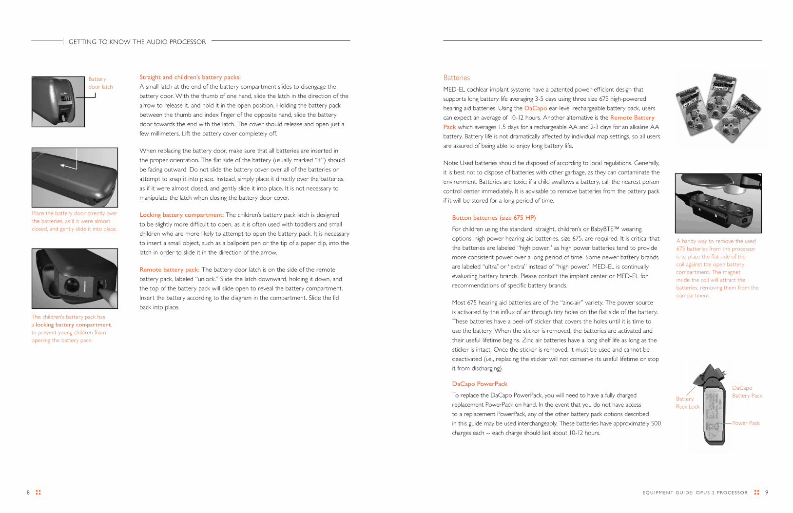
Batteries
MEd-EL cochlear implant systems have a patented power-efficient design that
supports long battery life averaging 3-5 days using three size 675 high-powered
hearing aid batteries. Using the DaCapo ear-level rechargeable battery pack, users
can expect an average of 10-12 hours. Another alternative is the Remote Battery
Pack which averages 1.5 days for a rechargeable AA and 2-3 days for an alkaline AA
battery. Battery life is not dramatically affected by individual map settings, so all users
are assured of being able to enjoy long battery life.
Note: Used batteries should be disposed of according to local regulations. Generally,
it is best not to dispose of batteries with other garbage, as they can contaminate the
environment. Batteries are toxic; if a child swallows a battery, call the nearest poison
control center immediately. It is advisable to remove batteries from the battery pack
if it will be stored for a long period of time.
Button batteries (size 675 HP)
For children using the standard, straight, children’s or BabyBTE™ wearing
options, high power hearing aid batteries, size 675, are required. It is critical that
the batteries are labeled “high power,” as high power batteries tend to provide
more consistent power over a long period of time. Some newer battery brands
are labeled “ultra” or “extra” instead of “high power.” MEd-EL is continually
evaluating battery brands. Please contact the implant center or MEd-EL for
recommendations of specific battery brands.
Most 675 hearing aid batteries are of the “zinc-air” variety. The power source
is activated by the influx of air through tiny holes on the flat side of the battery.
These batteries have a peel-off sticker that covers the holes until it is time to
use the battery. When the sticker is removed, the batteries are activated and
their useful lifetime begins. Zinc air batteries have a long shelf life as long as the
sticker is intact. Once the sticker is removed, it must be used and cannot be
deactivated (i.e., replacing the sticker will not conserve its useful lifetime or stop
it from discharging).
DaCapo PowerPack
To replace the daCapo PowerPack, you will need to have a fully charged
replacement PowerPack on hand. In the event that you do not have access
to a replacement PowerPack, any of the other battery pack options described
in this guide may be used interchangeably. These batteries have approximately 500
charges each -- each charge should last about 10-12 hours.
Straight and children’s battery packs:
A small latch at the end of the battery compartment slides to disengage the
battery door. With the thumb of one hand, slide the latch in the direction of the
arrow to release it, and hold it in the open position. Holding the battery pack
between the thumb and index finger of the opposite hand, slide the battery
door towards the end with the latch. The cover should release and open just a
few millimeters. Lift the battery cover completely off.
When replacing the battery door, make sure that all batteries are inserted in
the proper orientation. The flat side of the battery (usually marked “+”) should
be facing outward. do not slide the battery cover over all of the batteries or
attempt to snap it into place. Instead, simply place it directly over the batteries,
as if it were almost closed, and gently slide it into place. It is not necessary to
manipulate the latch when closing the battery door cover.
Locking battery compartment: The children’s battery pack latch is designed
to be slightly more difficult to open, as it is often used with toddlers and small
children who are more likely to attempt to open the battery pack. It is necessary
to insert a small object, such as a ballpoint pen or the tip of a paper clip, into the
latch in order to slide it in the direction of the arrow.
Remote battery pack: The battery door latch is on the side of the remote
battery pack, labeled “unlock.” Slide the latch downward, holding it down, and
the top of the battery pack will slide open to reveal the battery compartment.
Insert the battery according to the diagram in the compartment. Slide the lid
back into place.
The children’s battery pack has a locking battery compartment, to prevent young children from opening the battery pack.
A handy way to remove the used 675 batteries from the processor is to place the flat side of the coil against the open battery compartment. The magnet inside the coil will attract the batteries, removing them from the compartment.
GETTING TO KNOW THE AUdIO PrOCESSOr
daCapo Battery Pack
Power Pack
Battery Pack Lock
Place the battery door directly over the batteries, as if it were almost closed, and gently slide it into place.
Battery door latch
1110 E Q U I P M E N T G U I d E : O P U S 2 P r O C E S S O r
AA battery
The remote (rechargeable) battery pack utilizes one AA battery. The remote
battery pack uses one AA-size battery, either the rechargeable NiMH or non-
rechargeable alkaline type. Each child receives 3 NiMH rechargeable batteries
and a charger in the user kit. These batteries have a life of approximately 1000
charges each, and a charge should last 1 to 1.5 days. When the rechargeable
batteries have reached the end of their useful lifetime, they can be replaced
through MEd-EL. Some families purchase rechargeable batteries locally. MEd-EL
cannot vouch for the quality of these batteries, but does not discourage families
from trying other brands if desired. regular alkaline AA batteries can also be
used and should last 2-3 days. Alkaline (non-rechargeable) batteries must
NEVER be placed in the battery charger.
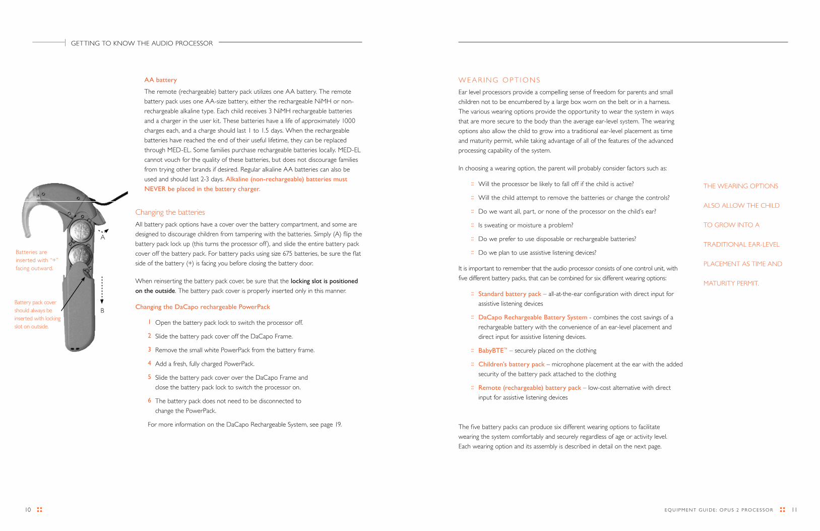
Changing the batteries
All battery pack options have a cover over the battery compartment, and some are
designed to discourage children from tampering with the batteries. Simply (A) flip the
battery pack lock up (this turns the processor off), and slide the entire battery pack
cover off the battery pack. For battery packs using size 675 batteries, be sure the flat
side of the battery (+) is facing you before closing the battery door.
When reinserting the battery pack cover, be sure that the locking slot is positioned
on the outside. The battery pack cover is properly inserted only in this manner.
Changing the DaCapo rechargeable PowerPack
1 Open the battery pack lock to switch the processor off.
2 Slide the battery pack cover off the daCapo Frame.
3 remove the small white PowerPack from the battery frame.
4 Add a fresh, fully charged PowerPack.
5 Slide the battery pack cover over the daCapo Frame and
close the battery pack lock to switch the processor on.
6 The battery pack does not need to be disconnected to
change the PowerPack.
For more information on the daCapo rechargeable System, see page 19.
W E A r I N G O P T I O N S
Ear level processors provide a compelling sense of freedom for parents and small
children not to be encumbered by a large box worn on the belt or in a harness.
The various wearing options provide the opportunity to wear the system in ways
that are more secure to the body than the average ear-level system. The wearing
options also allow the child to grow into a traditional ear-level placement as time
and maturity permit, while taking advantage of all of the features of the advanced
processing capability of the system.
In choosing a wearing option, the parent will probably consider factors such as:
:: Will the processor be likely to fall off if the child is active?
:: Will the child attempt to remove the batteries or change the controls?
:: do we want all, part, or none of the processor on the child’s ear?
:: Is sweating or moisture a problem?
:: do we prefer to use disposable or rechargeable batteries?
:: do we plan to use assistive listening devices?
It is important to remember that the audio processor consists of one control unit, with
five different battery packs, that can be combined for six different wearing options:
:: Standard battery pack – all-at-the-ear configuration with direct input for
assistive listening devices
:: DaCapo Rechargeable Battery System - combines the cost savings of a
rechargeable battery with the convenience of an ear-level placement and
direct input for assistive listening devices.
:: BabyBTE™ – securely placed on the clothing
:: Children’s battery pack – microphone placement at the ear with the added
security of the battery pack attached to the clothing
:: Remote (rechargeable) battery pack – low-cost alternative with direct
input for assistive listening devices
The five battery packs can produce six different wearing options to facilitate
wearing the system comfortably and securely regardless of age or activity level.
Each wearing option and its assembly is described in detail on the next page.
THE WEArING OPTIONS
ALSO ALLOW THE CHILd
TO GrOW INTO A
TrAdITIONAL EAr-LEVEL
PLACEMENT AS TIME ANd
MATUrITy PErMIT.
GETTING TO KNOW THE AUdIO PrOCESSOr
Batteries are inserted with “+” facing outward.
Battery pack cover should always be inserted with locking slot on outside.
A
B

1312 E Q U I P M E N T G U I d E : O P U S 2 P r O C E S S O r
Standard Battery Pack
Traditional BTE style Wireless access for external devices
•CONTROLUNIT • sTaNdaRdbaTTeRypaCk
BabyBTE™
BabyBTE™ (for infants) Activity pack for teens and adults
•CONTROLUNIT • sTRaIghTbaTTeRypaCk • LONgCOILCabLe
Children’s Battery Pack
Excellent for young children Activity pack for teens and adults
•CONTROLUNIT •ChILdReN’sbaTTeRypaCk
daCapo rechargeable Battery System
Cost-savings combined with the convenience of ear-level placement
Optional input for assistive listening devices
•CONTROLUNIT •daCapObaTTeRypaCk
remote Battery Pack
Cost saving and efficient Input jack for external devices
•CONTROLUNIT • RemOTebaTTeRypaCk • RemOTebaTTeRypaCkCabLe
A variety of options for infants, young children, and adultsOPUS 2 ProcessorEnlarged to show detail
DaCapo Frame and Battery Pack
Coil
Coil Cable
Battery Pack
On/Off Switch
Connecting Piece
Control Unit
Earhook
Microphone
LED indicator

1514 E Q U I P M E N T G U I d E : O P U S 2 P r O C E S S O r
THE BAByBTE™ HAS THE
AdVANTAGE OF ALLOWING
A yOUNG CHILd TO
BEGIN USING THE SAME
EAr-LEVEL AUdIO
PrOCESSOr THAT HE Or
SHE WILL USE FOr THE
LONG TErM, WHILE STILL
ACCOMMOdATING A
BABy’S SMALL EAr
ANd ACTIVITy LEVEL.
C H I L d r E N ’ S B A T T E r y P A C K
Who should use the children’s battery pack?
The children’s battery pack is the ideal configuration for active toddlers and
preschoolers, or older children who still require the security of a system that is
attached to the clothing. The control unit is worn at the ear, which provides optimal
microphone placement and easy visibility of the LEd indicator.
A cable allows the battery pack to be attached to the child’s clothing. This cable is
hard-wired into the battery pack and cannot be disconnected or replaced. If the
cable is damaged, the entire battery pack should be replaced.
How do I assemble the children’s battery pack?
1 Connect the standard 9.5 cm coil cable to the coil.
2 Connect the opposite end of the cable into the control unit. See page 5.
3 Add the children’s battery pack, fitting the cable plug into the control unit
with the cable slot positioned to accommodate the coil cable.
4 Insert the pins of the connecting piece into the small holes next to the serial
number of the control unit. If the connecting piece has long pins, position the
safety lock over the protruding pins on the other side of the processor. The
coil cable plug rests in the cutout section of the safety lock. Engage the safety
lock by sliding the small black lever.
5 Add the fixation bar or fixation clip to the battery pack, using the
screwdriver to tighten the accessory into place.
6 Add fresh batteries, and replace the battery pack cover.
7 Position the control unit on the child’s ear and position the battery pack on
the clothing in an inconspicuous place.
8 Turn the processor on (located on the tip of the battery pack). The red LEd
should illuminate 1, 2, 3 or 4 times to indicate which program position is
active. Place the coil on the head.
9 If desired, adjust processor settings using the FineTuner remote control.
B A B y B T E ™ ( A L S O C A L L E d ‘ A C T I V E W E A r ’ )
Who should use the BabyBTE™?
MEd-EL’s signature wearing option for infants and young children is the BabyBTE™. The BabyBTE has the advantage of allowing a young child to begin using the same ear-level processor that he or she will use for the long term, while still accommodating a baby’s small ear and activity level. For this wearing option, the entire BTE processor is placed on the clothing, and only the coil is placed over the implant on the head. The BabyBTE can also be used as an ‘activity pack’ for children or adults who participate in sports or other activities where a very secure placement is desired. For example, if the child is involved in an activity that requires wearing a helmet, using the activity pack allows the microphone of the processor to be positioned outside the helmet, with only the coil and cable fitting underneath.
When using the BabyBTE, it is important to be aware of the position of the microphone. It should be positioned in such a way that the majority of sound will be directed at the microphone, including the child’s own voice. Usually the best option is to position the
BabyBTE on the child’s shoulder, with the microphone facing forward.
How do I assemble the BabyBTE?1 Connect the coil cable to the coil. A longer coil cable (28 cm) is used for
this configuration than the ear-level wearing options to allow for flexibility in processor placement on the clothing.
2 Connect the opposite end of the cable into the processor. See page 5.
3 Add the straight battery pack, with the cable slot positioned to accommodate the coil cable.
4 Insert the pins of the connecting piece into the small holes next to the serial number of the control unit. If the connecting piece has long pins, position the safety lock over the protruding pins on the other side of the processor. The coil cable plug rests in the cutout section of the safety lock. Engage the safety lock by sliding the small black lever.
5 Add the fixation bar or fixation clip by attaching it to the two screw taps next to the labeling of the battery pack and using the screwdriver to tighten it into place.
6 Add fresh batteries, and replace the battery pack cover.
7 Position the BabyBTE on the child, pinning or clipping it into place on the clothing. If possible, try to position the processor so that it is out of the child’s reach, but with the microphone facing forward. Many parents choose to place the processor on the shoulder, facing up or forward.
8 Place the coil on the head, and turn the processor on (located on the tip of the battery pack). The red LEd should illuminate 1, 2, 3 or 4 times to indicate which program position is active.
9 If desired, adjust processor settings using the FineTuner remote control.
THE CHILdrEN’S BATTEry
PACK IS THE IdEAL
CONFIGUrATION FOr
ACTIVE TOddLErS ANd
PrESCHOOLErS, Or OLdEr
CHILdrEN WHO STILL
rEQUIrE THE SECUrITy
OF A SySTEM THAT
IS ATTACHEd TO THE
CLOTHING.
GETTING TO KNOW THE AUdIO PrOCESSOr

1716 E Q U I P M E N T G U I d E : O P U S 2 P r O C E S S O r
THE STANdArd
BATTEry PACK IS THE
MOST COMMON
CONFIGUrATION FOr
OLdEr CHILdrEN
ANd AdULTS.
A huggie-aid or an earmold may help keep the processor in position on the ear. Contact the implant clinic or audiologist for assistance.
S T A N d A r d B A T T E r y P A C K
Who should use the standard battery pack?
The standard battery pack is the most common configuration for older children
and adults. This configuration allows the entire processor to be worn at the ear.
In addition, a specialized battery pack cover (the FM Battery Pack Cover) provides
a standard 3-pin input jack for direct connection to assistive listening devices and
direct-link devices.
How do I assemble the standard battery pack?
1 Connect the standard 9.5 cm coil cable to the coil.
2 Connect the opposite end of the cable into the control unit. See page 5.
3 Add the standard battery pack, fitting the battery pack into the control unit
port with the cable slot positioned to accommodate the coil cable.
4 Insert the connecting piece to secure the battery pack to the control unit.
5 Add fresh batteries, and slide the battery pack cover over the battery pack
frame from the bottom.
6 Close the battery pack lock to turn the processor on. The red LEd should
illuminate 1, 2, 3 or 4 times to indicate which program position is active.
Place the coil on the head.
7 If desired, adjust processor settings using the FineTuner remote control.
8 To use the direct input function, use the FM battery pack cover instead of
the standard cover in step 5 above. To exchange battery pack covers, open
the battery pack lock and slide the battery pack cover off the battery pack
frame. Slide the new battery pack cover over the battery pack frame from
the bottom, and close the battery pack lock to turn the processor on. Most
modern FM systems can connect directly to the FM battery pack. Some
accessory devices may require the use of a patch cable. MEd-EL provides a
variety of patch cables for connection to battery-operated external listening
systems. See section “Connection to Accessory devices” on page 44 for
more information. For more information on connection to specific FM
systems, see current FM literature from MEd-EL.
S P E C I A L C O N S I d E r A T I O N S F O r S M A L L C H I L d r E N
The audio processor has several features that are particularly designed for small children. Among them:
Flexible programming to prevent accidental program, volume or sensitivity changes. It is possible to program each position and volume setting to the same map. In this configuration, changing the program or volume has no effect on the child’s listening experience. Contact the implant clinic for assistance.
FineTuner controls may be deactivated to prevent accidental program, volume or sensitivity changes.
Wearing options for small ears that remove the processor from the ear and place it securely on the clothing. See page 14.
The switch-free design of the processor prevents accidental program, volume or sensitivity changes.
The FineTuner accessory is not necessary during normal daily use for most children. The processor remembers its last settings, even after changing the batteries. Once the child’s program is set, the FineTuner is only needed to switch the telecoil on or off.
Locking earhook, which can be secured to the control unit with a small pin. See page 6.
Safety lock to prevent small children from disassembling the processor. See page 8.
Tamper-resistant battery covers on most battery packs, with a locking lever on the children’s battery pack. See page 8.
GETTING TO KNOW THE AUdIO PrOCESSOr
INTErCHANGEABLE
WEArING OPTIONS,
ENSUrE THAT THE
AUdIO PrOCESSOrS CAN
BE AdAPTEd TO THE
CHANGING rEQUIrEMENTS
OF GrOWING CHILdrEN.

1918 E Q U I P M E N T G U I d E : O P U S 2 P r O C E S S O r
d A C A P O r E C H A r G E A B L E B A T T E r y S y S T E M
Who should use the DaCapo rechargeable system?
The daCapo rechargeable battery system provides a cost effective choice for families but also offers the convenience of an ear-level placement. This option includes three rechargeable PowerPacks and a charger that will provide several years of use before the PowerPacks need to be replaced. The PowerPack provides 10-12 hours of continuous operation. The daCapo system is compatible with FM systems and other external devices, such as MP3 players, when using the FM Extension Kit. The FM battery pack cover includes a standard input port that is compatible with a wide variety of audio devices.
How do I connect the DaCapo battery frame?
To connect the daCapo Frame to the OPUS 2 Speech Processor, proceed as follows:
1 Open the battery pack lock.
2 remove the battery pack cover.
3 Pull out the connecting piece
4 remove the battery pack and connect thedaCapo Frame.
5 Secure the daCapo Frame to the processor by inserting the two pins of the connecting piece into the two holes on the bottom of the Control Unit. The pins must be inserted completely.
6 Slide the battery pack cover over the daCapo Frame and close the battery pack lock to switch the processor on.
r E M O T E ( r E C H A r G E A B L E ) B A T T E r y P A C K
Who should use the remote (rechargeable) configuration?
The remote configuration is ideal when cost is an issue, or when dexterity problems
preclude the use of the smaller battery packs. Families are provided with three
rechargeable size “AA” batteries and a charger, which will provide several years of
use before the batteries need to be replaced. They can also use off-the-shelf alkaline
(non-rechargeable) AA batteries. The battery pack is worn in a pocket or attached
to the clothing or belt using the small clip supplied with the system. The cable can
be replaced separately from the battery pack. The remote battery pack provides a
direct input port for connection to assistive listening devices.
How do I assemble the remote (rechargeable) configuration?
1 Connect the standard 9.5 cm coil cable to the coil.
2 Connect the opposite end of the cable into the control unit. See page 5.
3 Add the remote battery pack cable, fitting the cable plug into the
control unit with the cable slot positioned to accommodate the coil cable.
4 Plug the opposite end of the cable into the battery pack appropriate shaped
port .
5 Insert the pins of the connecting piece into the small holes next to the serial
number of the control unit. If the connecting piece has long pins, position the
safety lock over the protruding pins on the other side of the processor. The
coil cable plug rests in the cutout section of the safety lock. Engage the safety
lock by sliding the small black lever.
6 Add a fresh or fully charged battery.
7 Turn the ON/OFF switch (located on the remote battery pack) to “ON.”
The red LEd should illuminate 1, 2, 3 or 4 times to indicate which program
position is active. Place the coil on the head.
8 If desired, adjust processor settings using the FineTuner remote control.
8 The red LEd should illuminate briefly to indicate that the system is functioning.
9 To use the direct input function, locate the input port on the battery pack,
labeled with the symbol , under a small cover. The input port is a standard
3.5 mm (1/8”) stereo headphone jack. Next to the input port is a small
switch labeled EXT/MIX. This switch provides an opportunity to choose
whether the incoming signal will be mixed with the signal from the OPUS 2
microphone (on the head) or the accessory device alone. MEd-EL provides
a variety of patch cables for connection to assistive listening devices that do
not use a standard headphone plug. FM cables can also be purchased directly
through the FM manufacturers. For more information, see current
FM literature from MEd-EL.
detail of the input port, EXT/MIX and ON/OFF switches of the remote battery pack.
GETTING TO KNOW THE AUdIO PrOCESSOr
1
2
5
6
3
4

21E Q U I P M E N T G U I d E : O P U S 2 P r O C E S S O r 20
12H O W T O C O N F I G U r E T H E F I N E T U N E r
If a child comes to school with an OPUS 2 and a FineTuner, the two have most likely
already been synchronized to talk to each other. Once synchronized, the OPUS 2
and FineTuner stay in synchronization until one of the two pieces of equipment need
to be changed.
1 Turn off your OPUS 2 processor.
2 Place the coil of the OPUS 2 processor over the MT key on the FineTuner.
3 Turn on the OPUS 2 processor.
4 The audio processor and the FineTuner will be synchronized automatically.
5 Successful synchronization is indicated by a short blinking signal of the two
amber indicator lights on the FineTuner.
GETTING TO KNOW THE FINETUNEr™ rEMOTE CONTrOL
U S I N G T H E F I N E T U N E r
The FineTuner remote control is an accessory device that can be used
to optimize the audio processor in changing daily listening situations. The
OPUS 2 processor has an ON/OFF switch. All other functions are accessed
with the FineTuner, which transmits commands to the OPUS 2 processor.
With the FineTuner, parents, teachers and therapists can maintain control of
settings on the OPUS 2.
The FineTuner is not required for everyday use of the audio processor. When
the OPUS 2 is turned on, it will return to the same program, volume and
sensitivity settings that were in use before it was last turned off. The FineTuner
is configured for its designated OPUS 2 processor, so that only the target
OPUS 2 processor can execute a command from the FineTuner. The typical
maximum operating distance between the FineTuner and OPUS 2 processor is
approximately 80 cm (2.62 ft.). This range could be decreased near electrical
equipment.
The slim FineTuner™ is credit-card sized with a thickness of only 6 mm.
Successful synchronization is indicated by a short blinking signal of the two amber indicator lights on the FineTuner.
2322 E Q U I P M E N T G U I d E : O P U S 2 P r O C E S S O r
F I N E T U N E r K E y B O A r d L O C K F E A T U r E
Automatic keyboard lock: To avoid unintentional operation of a key, the FineTuner
features an optional automatic keyboard lock. This function electronically locks the
keyboard if no key is pressed for more than 10 seconds.
To activate the keyboard lock feature of your FineTuner, press the key for more
than 5 seconds to enter the program mode (the red and both amber indicator
lights on your FineTuner will both start blinking alternately indicating that you have
successfully entered the FineTuner’s program mode) and then the key to activate
the automatic keyboard lock (the FineTuner will confirm successful activation of the
automatic keyboard lock by a short blinking signal of the two amber indicator lights).
To deactivate the automatic keyboard lock enter the program mode just as
described above and press the key. As above the FineTuner will confirm
successful deactivation of the automatic keyboard lock by a short blinking signal of
the two amber indicator lights.
ATTENTION: To enter the program mode while the keyboard lock is active, the
key must be pressed twice (second time for more than 5 seconds).
To activate a certain function while the keyboard lock is active, press the desired
function key twice. The first click temporarily unlocks the keyboard, the second
click executes the command. After 10 seconds without pressing another key, the
keyboard lock is active again.
W H E N T O C O N F I G U r E T H E F I N E T U N E rIt should only occasionally be necessary to synchronize the FineTuner and
audio processor. Examples include use of a back-up processor or second FineTuner.
For children with a cochlear implant on each ear (bilaterally implanted), one
FineTuner can be used for both ears. However, a FineTuner can only be synchronized
with one processor for each ear..
The FineTuner only needs to be configured:
1 At the initial processor fitting.
2 When using a different or additional processor (e.g., back-up, loaner, or
replacement).
3 When using a different FineTuner (e.g., back-up, loaner, replacement, or
bilateral).
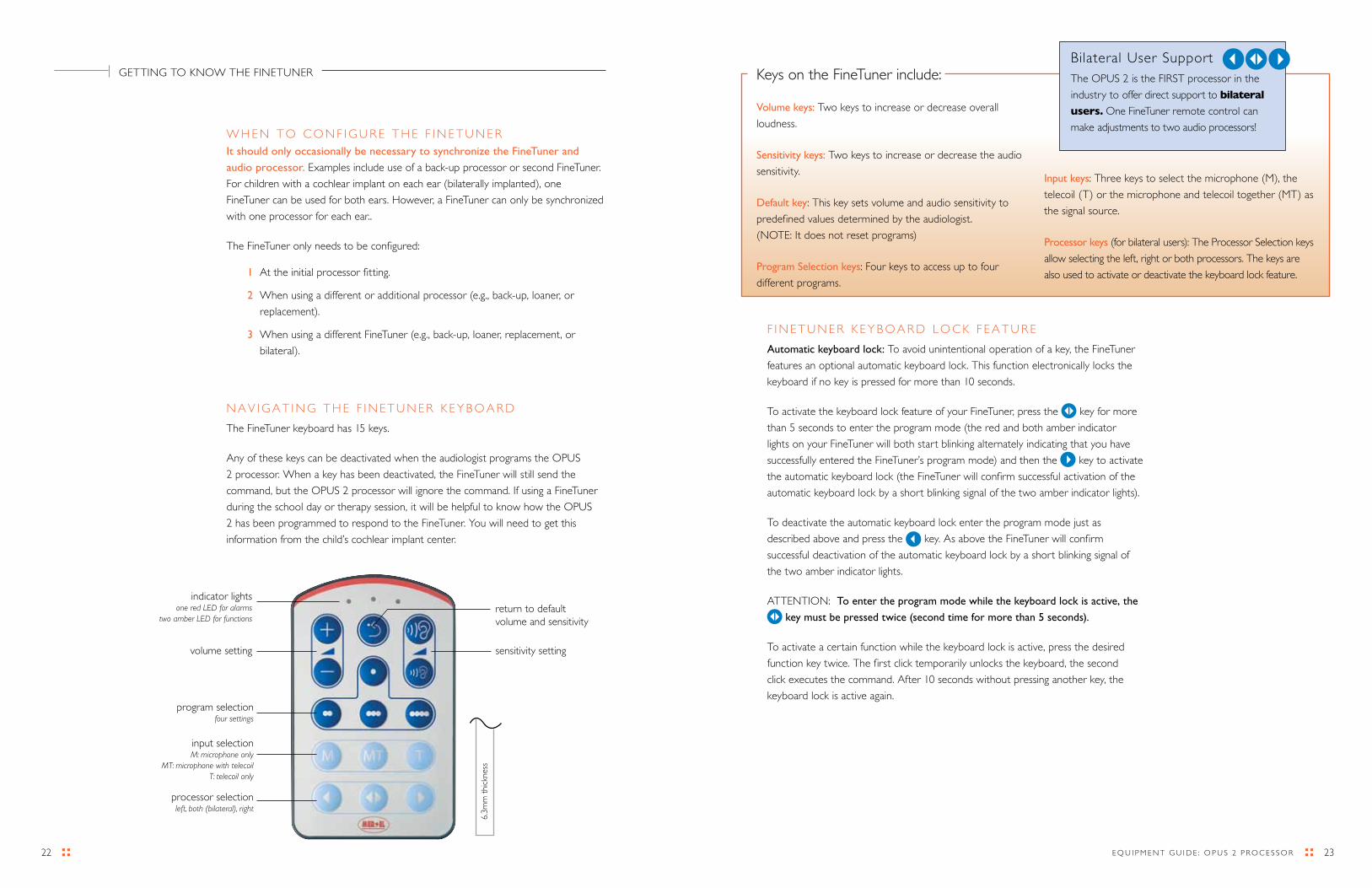
N A V I G A T I N G T H E F I N E T U N E r K E y B O A r d
The FineTuner keyboard has 15 keys.
Any of these keys can be deactivated when the audiologist programs the OPUS
2 processor. When a key has been deactivated, the FineTuner will still send the
command, but the OPUS 2 processor will ignore the command. If using a FineTuner
during the school day or therapy session, it will be helpful to know how the OPUS
2 has been programmed to respond to the FineTuner. you will need to get this
information from the child’s cochlear implant center.
volume setting
program selection four settings
input selection M: microphone only
MT: microphone with telecoil T: telecoil only
processor selection left, both (bilateral), right
indicator lights one red LED for alarms
two amber LED for functions
sensitivity setting
return to default volume and sensitivity
6.3m
m t
hick
ness
Bilateral User SupportThe OPUS 2 is the FIrST processor in the
industry to offer direct support to bilateral
users. One FineTuner remote control can
make adjustments to two audio processors!
Keys on the FineTuner include:
Volume keys: Two keys to increase or decrease overall
loudness.
Sensitivity keys: Two keys to increase or decrease the audio
sensitivity.
Default key: This key sets volume and audio sensitivity to
predefined values determined by the audiologist.
(NOTE: It does not reset programs)
Program Selection keys: Four keys to access up to four
different programs.
Input keys: Three keys to select the microphone (M), the
telecoil (T) or the microphone and telecoil together (MT) as
the signal source.
Processor keys (for bilateral users): The Processor Selection keys
allow selecting the left, right or both processors. The keys are
also used to activate or deactivate the keyboard lock feature.
GETTING TO KNOW THE FINETUNEr

2524 E Q U I P M E N T G U I d E : O P U S 2 P r O C E S S O r
C H A N G I N G T H E F I N E T U N E r B A T T E r y
To conserve power, the FineTuner will only transmit a command for a few seconds.
For this reason, you should press the desired key once for every change you wish to
make. The FineTuner battery status is checked after each transmission. When the
batteries are low, a red indicator light on the FineTuner blinks three times, indicating
that the battery should be changed. The FineTuner battery should last for at least
several months.
To change the battery:
1 Open the lid on the back of the FineTuner with a small screwdriver.
2 replace the used button battery (type Cr2025) by removing it with the coil
magnet or by gently shaking it into your hand. Try not to touch the battery
contacts.
3 Insert the new battery with the “+” sign facing up.
4 Close the lid by carefully inserting it on the right side, then sliding it in place
and tightening the screw.
T r O U B L E S H O O T I N G T H E F I N E T U N E r
If the OPUS 2 does not respond to FineTuner commands, there can be a number
of potential reasons and subsequently there are several things to try. For example,
the OPUS 2 needs to be within approximately 2.6 feet of the FineTuner in order to
respond. Other examples are outlined in the table below.
F I N E T U N E r I N d I C A T O r L I G H T S I G N A L S
The FineTuner has 3 indicator lights that can provide useful information about how
the FineTuner is operating. Indicator lights are located above the FineTuner keyboard
and include a red LEd in the center with amber LEds to the left and right. These
LEds can provide the following information:
rEd (center)
AMBEr (left side)
AMBEr (right side)
FUNCTION LIGHT PATTERN MEANING
Keyboard locked If you press a key while the keyboard is locked, the red indicator light comes on.
In order to conserve power, the red indicator light will go off after 5 seconds even if the key is still pressed.
Transmitting Information
Left or right (or both) lights blink according to the side mode of the FineTuner.
Indicator lights will blink when signals are transmitted (the indicator light blinking corresponds to the processor being modified–eitherright,leftorbothsidesforbilateralusers.)
To save energy, the FineTuner stops transmitting (and the indicator light stops blinking) after 3 seconds, even if the key is still pressed.
Switching Sides To switch from the left to the right side, press the corresponding button and the amber light will illuminate.
To switch both sides at once (for bilateral users), press the button in the center. Both amber lights will illuminate.
Programming Mode Press for more than 5 seconds to enter the programming mode.
Thethreeindicatorlightswillstartflashingalternately.
When the red indicator light is on, the two amber indicator lights are off and vice versa.
Low Battery
If a low battery status is detected, the red indicator light (center) will blink in a regular pattern – 3 blinks at a time.
Configuration Successful
IfconfigurationofyourFineTunerwassuccessful,oriftheautomatic keyboard lock feature was successfully activated/deactivated, both amber indicator lights will illuminate for approximately one second.
(+ 5 seconds)
( blinks 3 times )
(illuminates for one second)
Insert the new battery with the “+” sign facing up.
GETTING TO KNOW THE FINETUNEr
Problem description Possible cause Action to take Remarks
OPUS 2 does not respond to FineTuner commands
OPUS 2 out of FineTuner trans-mission range (~0.8 m)
Move closer If the problem persists, replace FineTuner or processor
Automatic keyboard lock active deactivate Automatic keyboardlock
Interference is present and blocking transmission Go to different location
OPUS 2 and FineTuner are not synchronized Synchronize
FineTuner battery low replace battery
Commands in OPUS 2 are disabled Contact your audiologist
LEd in OPUS 2 is disabled Contact your audiologist
27E Q U I P M E N T G U I d E : O P U S 2 P r O C E S S O r 26
1
Many professionals like to use a popular quick test called the “Six Sound Test”
developed by the late daniel Ling. This quick stimulus/response test uses
isolated speech sounds that cover the entire frequency spectrum of speech.
The six sounds are:
“mm” as in “mmm that’s good” (not “em” as in “the letter M”)
“ah” as in “father”.
“ee” as in “bee”
“oo” as in “boot”
“ss” (not ‘ess’)
and “sh”
The teacher should present each sound, one at a time, and expect the child
to indicate that it was heard. Each sound should be presented using the same
intonation and duration so the child can’t guess the sound based on those clues. For
example, using a rising intonation for one sound and not others will cue the child,
as will using a longer presentation of “mm”, “ss” or “sh” than for the vowels. The
presentation order needs to be varied, and additional (unexpected) stimuli included
from time to time, such as the child’s name or other familiar words, so that the task
is not overly predictable.
responses will vary depending on the age, maturity and listening level of the child. In
the very beginning, the response may be inconsistent and will need
to be encouraged and taught. New implant users will not typically hear the
difference between sounds – only that a sound was made. This is referred to
as the ability to detect a sound. At this level, the listener is expected to indicate she
has heard the stimulus by giving a simple response. The response can be anything
you choose to teach: pointing to the ear, dropping a toy into a container, turning to
look at you, vocalizing, etc.
Soon we expect the child to move on to a higher level of auditory ability:
discrimination. This means the child is beginning to recognize that sounds are
different. For the purposes of these early tasks, we are expecting the child to detect
and discriminate a set of phonemes, which are the individual sounds that make up
the complex body of spoken language. during the discrimination phase, the child
may begin to identify each phoneme as evidenced by her ability to repeat what
is said to her. For example, the adult may say one of the six sounds (oo) and the
child consistently repeats back, “oo.” This is an exciting development because it
demonstrates that for this phoneme, the child is able to detect (hear the phoneme),
discriminate (distinguish it from other phonemes) and identify (label it by virtue of
repeating it).
IS IT WOrKING? A TrOUBLESHOOTING PrIMEr
d A I L y L I S T E N I N G C H E C K S
In order to feel confident that the system is working and the child is receiving
the best sound possible, it is advisable to formally check the system every day. It
is helpful to think about this from two viewpoints, the viewpoint of functioning
equipment and also the viewpoint of good auditory discrimination. Obviously
the child doesn’t hear properly if the equipment itself is not working. But it is
also important to consider whether the child’s hearing is optimal throughout the
day and from day to day as well.
In order to establish a consistent and replicable method of evaluating the
equipment and the child’s auditory discrimination, many parents, therapists, and
educators do a routine daily listening check, preferably at the beginning of the
day or session. This quick check should take no more than 1-2 minutes, and
will help to establish your comfort zone about the function of the device and
the child’s ability to make use of audition. In addition, some educators find it
beneficial when working with very young children to repeat the listening check
after PE or recess. The listening check should also be employed any time there is
suspicion that the child is not responding in his or her typical fashion.
Verifying auditory detection and discrimination
Because we are checking for auditory ability, it is critical that the child has no
access to visual cues during the daily listening check. Ideally, the child should be
positioned next to and slightly in front of you (with the implant side nearest you)
so that no speechreading cues are available. Another option for removing visual
cues is to fashion a ‘listening screen’ from an embroidery hoop stretched with a
lightweight but opaque fabric, such as 2 layers of stereo speaker cloth. do not
use paper or cardboard, as the sound will be deflected, making the hearing task
more difficult.
3
2928 E Q U I P M E N T G U I d E : O P U S 2 P r O C E S S O r
A daily listening check can also be used to teach the child to indicate when the device
is not working properly. Children with cochlear implants should be encouraged to
become their own strongest advocates for good hearing. It is a good idea to teach
the vocabulary of listening as the child’s listening skills begin to improve. Here are
some target sentences and phrases that can help the child become responsible for
the device and its sound quality:
“I need new batteries.”
“My processor sounds different.”
“The sound is going on and off.”
“your voice sounds funny.”
“I can hear well today.”
“What is that sound?”
“I heard that but I didn’t understand it.”
“My processor is not working” or “My processor is broken.”
With an older child or more experienced child after presentation of the Ling Sounds
to determine accuracy of discrimination and production, you may want to use the
following target sentences. “Can you hear me” or “Can you hear me well.” “Tell me
what you hear” and have him repeat several short sentences. Vary your sentences
from day to day to decrease the chance of prediction on the part of the child.
As the child’s auditory skills increase and the ability to repeat a sound develops, you
want to move toward having the child repeat back each speech sound after you say
it. When the child first attempts to repeat the sounds you say, their approximation
may not even resemble your model, but a vocalization is an indication a sound
was heard and should be encouraged. As the child’s ability to modify his or her
own speech to match your model improves, the responses to the various sounds
should begin to sound different, and should come closer and closer to accurately
pronouncing the sound.
The important thing to remember here is this: if the child can’t consistently repeat
sounds accurately in general, but can indicate that a sound was heard, then you
are measuring detection. Any indication that the child heard the sound is good.
Once the child can consistently indicate that sounds are different from each other,
you begin measuring discrimination. If the task is performed regularly, you will
become familiar with the child’s typical responses, and this quick test becomes even
more useful. Once a consistent response is achieved, any changes from this baseline
response, such as a change in the child’s typical pronunciation, take on added
meaning, and may indicate there is a need for a change in the map.
NOTE: Keep in mind the difference between discrimination difficulties and speech
production difficulties. It is common for children with developing articulation skills to
mispronounce or to be unable to pronounce certain speech sounds, even though the
sound is heard. By experimenting with detecting and discriminating the target sound
along with the mispronunciation, you may be able to determine whether the child
can hear the sound, but just can’t produce it accurately.
This very quick and simple method of evaluating detection and discrimination can
provide a great deal of insight into the child’s hearing acuity without any additional
equipment. It can also be a fun way to reinforce listening skills and help the child
experience success. Once the child knows the routine and the task, you will have a
good sense of their hearing function from day to day, and small changes in hearing
will quickly become apparent. Many educators turn the daily listening check into
a fun game, often allowing the child a turn to be the speaker as well. This can
provide a short one-on-one opportunity to praise and build confidence in the child’s
developing listening skills.
A TrOUBLESHOOTING PrIMEr
3130 E Q U I P M E N T G U I d E : O P U S 2 P r O C E S S O r
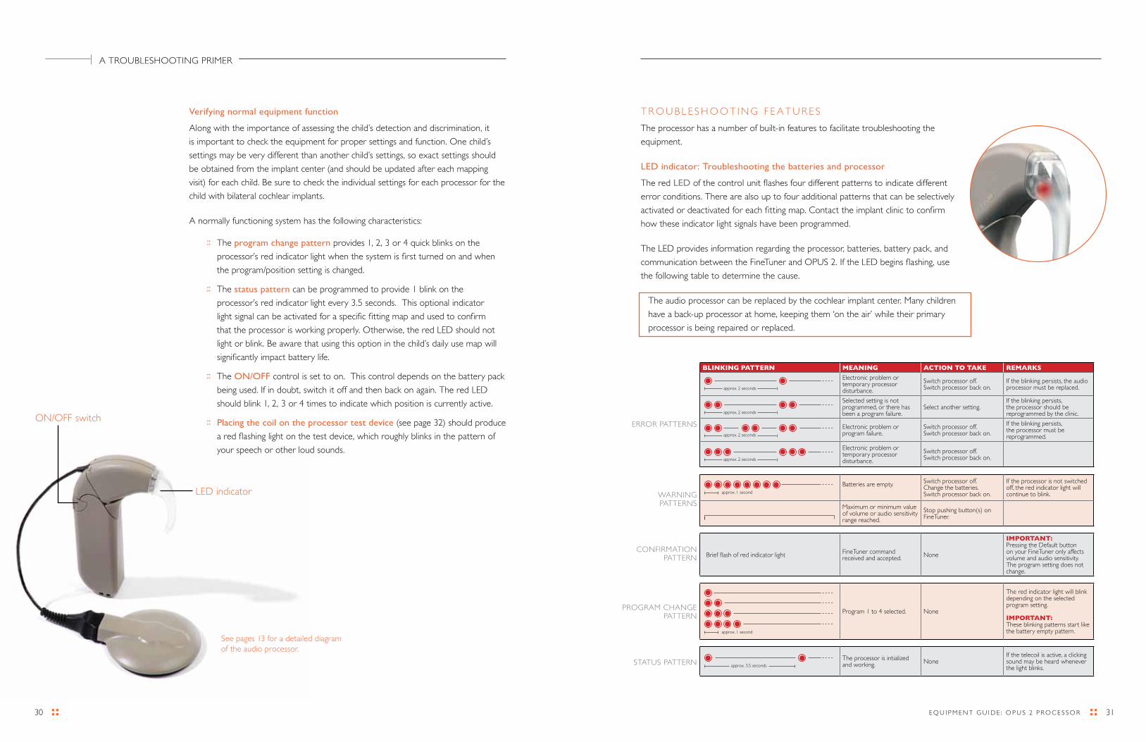
ON/OFF switch
LEd indicator
T r O U B L E S H O O T I N G F E A T U r E S
The processor has a number of built-in features to facilitate troubleshooting the
equipment.
LED indicator: Troubleshooting the batteries and processor
The red LED of the control unit flashes four different patterns to indicate different
error conditions. There are also up to four additional patterns that can be selectively
activated or deactivated for each fitting map. Contact the implant clinic to confirm
how these indicator light signals have been programmed.
The LEd provides information regarding the processor, batteries, battery pack, and
communication between the FineTuner and OPUS 2. If the LEd begins flashing, use
the following table to determine the cause.
The audio processor can be replaced by the cochlear implant center. Many children
have a back-up processor at home, keeping them ‘on the air’ while their primary
processor is being repaired or replaced.
Verifying normal equipment function
Along with the importance of assessing the child’s detection and discrimination, it
is important to check the equipment for proper settings and function. One child’s
settings may be very different than another child’s settings, so exact settings should
be obtained from the implant center (and should be updated after each mapping
visit) for each child. Be sure to check the individual settings for each processor for the
child with bilateral cochlear implants.
A normally functioning system has the following characteristics:
:: The program change pattern provides 1, 2, 3 or 4 quick blinks on the
processor’s red indicator light when the system is first turned on and when
the program/position setting is changed.
:: The status pattern can be programmed to provide 1 blink on the
processor’s red indicator light every 3.5 seconds. This optional indicator
light signal can be activated for a specific fitting map and used to confirm
that the processor is working properly. Otherwise, the red LEd should not
light or blink. Be aware that using this option in the child’s daily use map will
significantly impact battery life.
:: The ON/OFF control is set to on. This control depends on the battery pack
being used. If in doubt, switch it off and then back on again. The red LEd
should blink 1, 2, 3 or 4 times to indicate which position is currently active.
:: Placing the coil on the processor test device (see page 32) should produce
a red flashing light on the test device, which roughly blinks in the pattern of
your speech or other loud sounds.
A TrOUBLESHOOTING PrIMEr
See pages 13 for a detailed diagram of the audio processor.
BLINKING PATTERN MEANING ACTION TO TAKE REMARKS
Electronic problem or temporary processor disturbance.
Switch processor off.Switch processor back on.
If the blinking persists, the audio processor must be replaced.
Selected setting is not programmed, or there has been a program failure.
Select another setting.If the blinking persists, the processor should be reprogrammed by the clinic.
Electronic problem or program failure.
Switch processor off.Switch processor back on.
If the blinking persists, the processor must be reprogrammed.
Electronic problem or temporary processor disturbance.
Switch processor off.Switch processor back on.
Batteries are empty. Switch processor off.Change the batteries.Switch processor back on.
If the processor is not switched off, the red indicator light will continue to blink.
Maximum or minimum value of volume or audio sensitivity range reached.
Stop pushing button(s) on FineTuner.
briefflashofredindicatorlight FineTuner command received and accepted. None
IMPORTANT:Pressing the default button on your FineTuner only affects volume and audio sensitivity. The program setting does not change.
Program 1 to 4 selected. None
The red indicator light will blink depending on the selected program setting.
IMPORTANT:These blinking patterns start like the battery empty pattern.
The processor is intialized and working. None
If the telecoil is active, a clicking sound may be heard whenever the light blinks.
CONFIrMATION PATTErN
PrOGrAM CHANGE PATTErN
STATUS PATTErN
approx. 2 seconds
approx. 2 seconds
approx. 2 seconds
approx. 2 seconds
approx. 3.5 seconds
approx. 1 second
approx. 1 second
ErrOr PATTErNS
WArNING PATTErNS
3332 E Q U I P M E N T G U I d E : O P U S 2 P r O C E S S O r
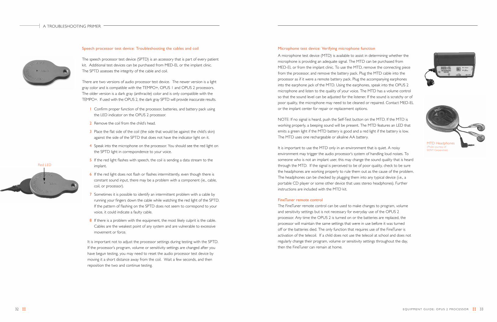
Microphone test device: Verifying microphone function
A microphone test device (MTd) is available to assist in determining whether the
microphone is providing an adequate signal. The MTd can be purchased from
MEd-EL or from the implant clinic. To use the MTd, remove the connecting piece
from the processor, and remove the battery pack. Plug the MTd cable into the
processor as if it were a remote battery pack. Plug the accompanying earphones
into the earphone jack of the MTd. Using the earphones, speak into the OPUS 2
microphone and listen to the quality of your voice. The MTd has a volume control
so that the sound level can be adjusted for the listener. If the sound is scratchy or of
poor quality, the microphone may need to be cleaned or repaired. Contact MEd-EL
or the implant center for repair or replacement options.
NOTE: If no signal is heard, push the Self-Test button on the MTd. If the MTd is
working properly, a beeping sound will be present. The MTd features an LEd that
emits a green light if the MTd battery is good and a red light if the battery is low.
The MTd uses one rechargeable or alkaline AA battery.
It is important to use the MTd only in an environment that is quiet. A noisy
environment may trigger the audio processor’s system of handling loud noises. To
someone who is not an implant user, this may change the sound quality that is heard
through the MTd. If the signal is perceived to be of poor quality, check to be sure
the headphones are working properly to rule them out as the cause of the problem.
The headphones can be checked by plugging them into any typical device (i.e., a
portable Cd player or some other device that uses stereo headphones). Further
instructions are included with the MTd kit.
FineTuner remote control
The FineTuner remote control can be used to make changes to program, volume
and sensitivity settings but is not necessary for everyday use of the OPUS 2
processor. Any time the OPUS 2 is turned on or the batteries are replaced, the
processor will maintain the same settings that were in use before it was turned
off or the batteries died. The only function that requires use of the FineTuner is
activation of the telecoil. If a child does not use the telecoil at school and does not
regularly change their program, volume or sensitivity settings throughout the day,
then the FineTuner can remain at home.
Speech processor test device: Troubleshooting the cables and coil
The speech processor test device (SPTd) is an accessory that is part of every patient
kit. Additional test devices can be purchased from MEd-EL or the implant clinic.
The SPTd assesses the integrity of the cable and coil.
There are two versions of audio processor test device. The newer version is a light
gray color and is compatible with the TEMPO+, OPUS 1 and OPUS 2 processors.
The older version is a dark gray (anthracite) color and is only compatible with the
TEMPO+. If used with the OPUS 2, the dark gray SPTd will provide inaccurate results.
1 Confirm proper function of the processor, batteries, and battery pack using
the LEd indicator on the OPUS 2 processor.
2 remove the coil from the child’s head.
3 Place the flat side of the coil (the side that would be against the child’s skin)
against the side of the SPTd that does not have the indicator light on it.
4 Speak into the microphone on the processor. you should see the red light on
the SPTd light in correspondence to your voice.
5 If the red light flashes with speech, the coil is sending a data stream to the
implant.
6 If the red light does not flash or flashes intermittently, even though there is
constant sound input, there may be a problem with a component (ie., cable,
coil, or processor).
7 Sometimes it is possible to identify an intermittent problem with a cable by
running your fingers down the cable while watching the red light of the SPTd.
If the pattern of flashing on the SPTd does not seem to correspond to your
voice, it could indicate a faulty cable.
8 If there is a problem with the equipment, the most likely culprit is the cable.
Cables are the weakest point of any system and are vulnerable to excessive
movement or force.
It is important not to adjust the processor settings during testing with the SPTd.
If the processor’s program, volume or sensitivity settings are changed after you
have begun testing, you may need to reset the audio processor test device by
moving it a short distance away from the coil. Wait a few seconds, and then
reposition the two and continue testing.
red LEd
MTd Headphones(Photo courtesy of SONy Corporation)
A TrOUBLESHOOTING PrIMEr

35E Q U I P M E N T G U I d E : O P U S 2 P r O C E S S O r 34
Problem: The system appears to be working (no flashing lights) but the child is not
responding to sound.
Solution: After each step, check to see whether sound is restored:
:: Switch the processor off and back on. The red LEd should blink 1, 2, 3 or 4 times
to indicate which program position is currently active. Be sure that the current
program is set to the child’s typical daily use settings.
:: Use the audio processor test device (SPTd) to determine whether the coil is
sending information to the implant. See page 32 for instructions
:: If the SPTd does not light in response to loud sounds, try replacing the cable.
See pages 5 and 13-19 for instruction on assembling/disassembling the system,
depending on the child’s wearing option, in order to change the cable.
:: If a spare cable does not solve the problem, use the microphone test device (if
available) to verify that the child’s microphone is functioning properly. See page 33
for instructions.
:: If the FineTuner is available, check to see whether volume and sensitivity settings
are adequate. If these settings are too low, the child may not be able to detect
sound at normal levels. Use the FineTuner remote control to start at the child’s
default volume and sensitivity settings. If possible, gradually increase volume
while monitoring the child’s response to sound. If the child was hearing normally at
an earlier point in time, and the FineTuner has not been used since that time, then
volume and sensitivity settings are not likely to be the problem.
:: If, after these steps, you cannot determine the problem, it is a more complex
issue. Further troubleshooting will require a spare battery pack, coil, and possibly a
control unit. If needed, you can contact the child’s parent, implant center, or
MEd-EL for troubleshooting assistance.
Problem: The child is detecting sound, but discrimination is poorer than usual.
Solution: Check discrimination after each step:
:: Check to see that the child is using his or her typical daily use program.
:: Use the microphone test device (if available) to assess the integrity of the microphone.
:: Check to see that the volume and sensitivity settings are adequate. Use the FineTuner
remote control (if available) to start at the child’s default volume and sensitivity settings.
If possible, gradually increase volume while monitoring the child’s response to sound.
:: Contact the implant center to discuss whether a mapping visit is appropriate.
Important feedback to the center will include:
– The type of errors the child appears to be making
– Whether the problem was of sudden or gradual onset
– The child’s overall performance level
A S T E P - B y - S T E P T r O U B L E S H O O T I N G G U I d E
Most routine problems that occur with the processor will be easy to solve in the classroom. The batteries need to be replaced every 3-5 days (for size 675) or daily (for size AA). The power pack for the daCapo rechargeable system needs to be replaced with a new fully charged pack every 10-12 hours. Cables are also prone to normal wear and tear, and will need to be replaced from time to time.
TIP: When troubleshooting the system using spare parts, it is best to try changing just one part at a time. If you swap out several parts at once, it is difficult to be completely sure of the original cause of the problem, and functioning equipment may be discarded unnecessarily.
TIP: When troubleshooting using spare parts, it is helpful to keep spare equipment separate from the questionable equipment as you change out each part. It is very easy to get the two sets confused!
Problem: LEd is flashing.
Solution: refer to LEd table (page 31).
If you are certain the batteries are fresh, and the processor has been reset, it is possible that the battery pack or the connection between the battery pack and processor is faulty. This problem needs to be investigated further with spare equipment (a spare battery pack and possibly a spare processor) to determine the fault.
Problem: Battery life is very short when using size 675 batteries (substantially less than 3 days).
Solution: Check battery life after each step:
:: Some brands and/or types of batteries work better than others. For specific battery recommendations, you may contact MEd-EL or the implant clinic. you may also want to experiment with different batteries to find one that works best for you. An easy way to keep track of battery life is to place the battery tab (sticker on 675 zinc-air batteries) on the calendar when you remove it for use.
:: Check the battery compartment. Zinc-air batteries need air circulation in order to maintain power, so make sure that the openings at the bottom of the battery pack cover (standard and daCapo battery packs) are not covered. For the straight and children’s battery packs, the battery pack cover/lid should fit so that there is a very thin opening where the battery cover meets the battery pack.
:: Check to see that the battery door is not too loose. If the battery pack or cover become worn, the battery door may not hold tightly enough, resulting in poor contact between the batteries and the contacts in the battery pack. A spare battery door is provided in the patient kit, or can be obtained from MEd-EL or the implant clinic.
:: Use of direct input assistive listening devices, especially those without their own power source, may noticeably decrease the normal battery life.
A TrOUBLESHOOTING PrIMEr
3736 E Q U I P M E N T G U I d E : O P U S 2 P r O C E S S O r
K E E P I N G S P A r E E Q U I P M E N T O N H A N d
The following basic “kit” will handle most routine problems and replacements for
basic trouble shooting. Items specific to the device (i.e. cables, earhooks and fixation
devices) can be obtained from the parent, the implant clinic or from MEd-EL.
It is best to keep everything together in a small plastic container where they are
easily accessible:
:: High power zinc air batteries have a long shelf life, so there is little concern
that the useful lifetime will diminish, as long as the stick-on tab that covers
the air vents has never been removed. Once the tab has been removed,
however, the battery life will drain even if the tab is replaced.
:: A spare coil cable is also extremely useful to have on hand. Although the
system is designed to be durable, cables are particularly subject to wear and
tear and need to be replaced from time to time.
:: Consider keeping a spare earhook or other fixation device on hand.
:: Small screwdriver, like those used on eyeglasses, for detaching locked
fixation devices or earhooks. MEd-EL provides a specialized pin removal tool
in the patient’s kit.
:: If the child uses the children’s battery pack or the safety lock, consider
keeping something that will open the recessed lock. The screwdriver
mentioned above will work, or an unfolded paper clip. Even a ballpoint pen will
do the job.
:: Laminated troubleshooting card “MEd-EL Made Easy.” This is a smaller
sized copy of the chart on page 25. These can be obtained at no charge
from MEd-EL or the implant center.
:: If the child uses the DaCapo battery pack, consider whether it makes
sense to keep a spare PowerPack on hand. A charger will be needed to
maintain a charge. Alternatively, a spare battery pack that uses standard 675
batteries might be useful (ensure that you have all the necessary accessories
for connection, including an earhook).
For more advanced troubleshooting, a spare battery pack, coil and pre-programmed
control unit will be needed (unless your facility provides mapping services).
MEd-EL offers families the option of purchasing a spare processor at the time
of implantation, and many implant centers and families opt to do this. If the child
has a complete, functioning spare system, problems can be solved instantly and
troubleshooting one part at a time is much easier. If the family does not have a spare
system, additional troubleshooting equipment may be purchased from the implant
clinic or from MEd-EL if desired.
Additional troubleshooting tools, such as the audio processor test device (SPTd) or the microphone test device (MTd) can be particularly helpful. All patient kits contain one SPTd, and additional test devices can be purchased from the clinic or from MEd-EL. The MTd is purchased separately. Please call MEd-EL for current pricing and ordering information.
Problem: Parts of the equipment seem to be broken (earhook, battery door cover, etc).
Solution: Contact the parent, the implant team, or MEd-EL for assistance in replacing
parts.
Problem: The OPUS 2 does not seem to be responding to FineTuner commands.
Solution: Check the OPUS 2’s response after each step:
:: Move the FineTuner closer to the OPUS 2 processor. They need to be within ~2.6 feet of one another.
:: Press the desired command twice. If the keyboard is locked, a red light will blink each time you press a key. Pressing the desired key twice will temporarily override the keyboard lock and execute the command.
:: Move away from any electrical or electronic equipment that could be interfering with transmission between the FineTuner and OPUS 2.
:: Synchronize the FineTuner and OPUS 2. See instructions for “how to configure the FineTuner” on page 21.
:: Change the FineTuner battery. The red LEd on the FineTuner will blink 3 times after pressing any key when the battery is low. If a malfunction of the FineTuner is suspected, reset the FineTuner by removing the battery, waiting a few minutes, and reinserting the battery.
:: Keep in mind that FineTuner commands and the FineTuner indicator light signal of the OPUS 2 can be deactivated by the implant center during programming.
Problem: I can’t deactivate the FineTuner keyboard lock feature.
Solution: To deactivate the keyboard lock feature of your FineTuner, press
the key for more than 5 seconds to enter the program mode
(the red and both amber indicator lights on your FineTuner will both
start blinking alternately indicating that you have successfully entered
the FineTuner’s program mode) and then the key to deactivate
the automatic keyboard lock (the FineTuner will confirm successful
deactivation of the automatic keyboard lock by a short blinking
signal of the two amber indicator lights).
A TrOUBLESHOOTING PrIMEr
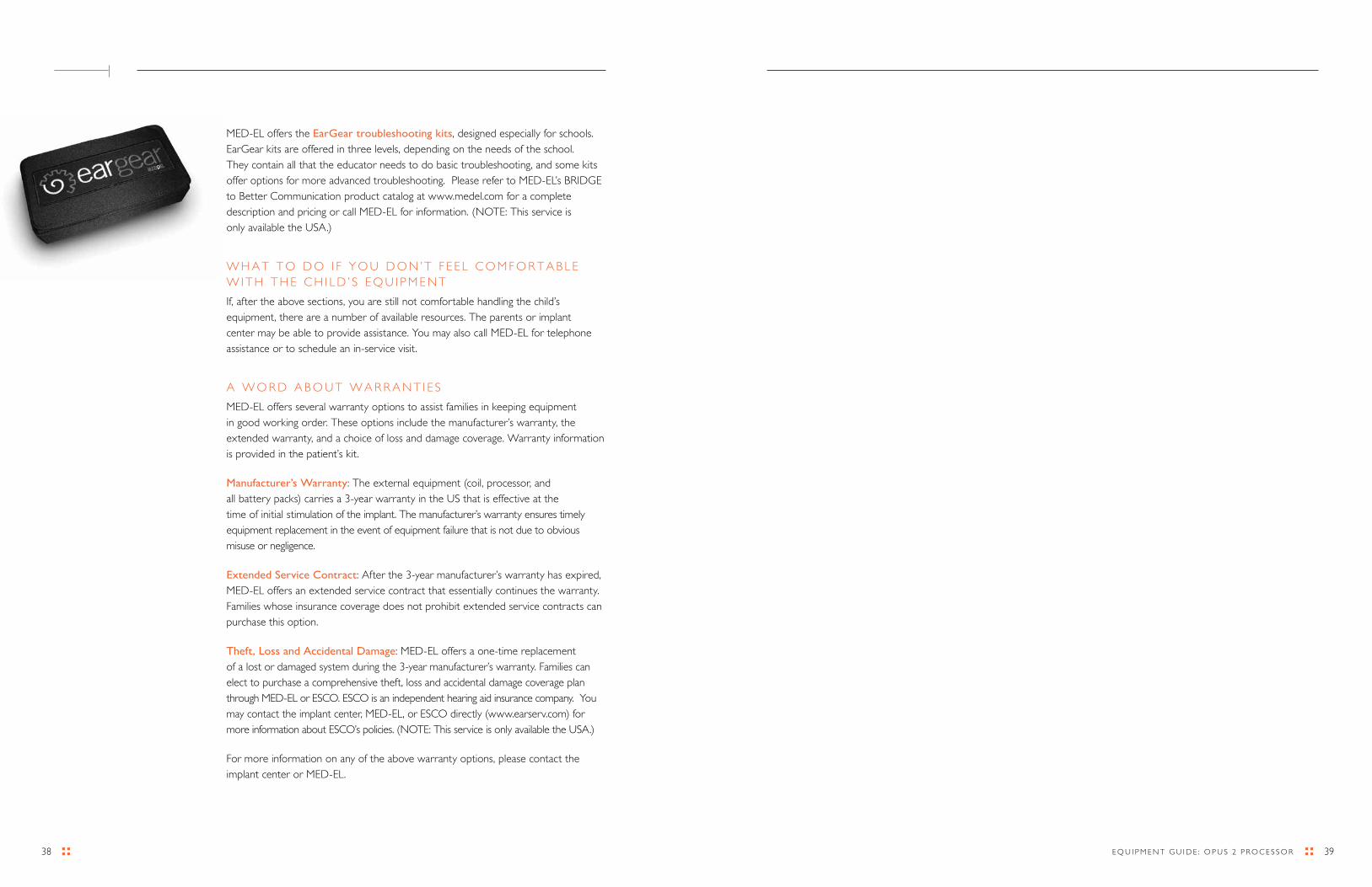
3938 E Q U I P M E N T G U I d E : O P U S 2 P r O C E S S O r
MEd-EL offers the EarGear troubleshooting kits, designed especially for schools. EarGear kits are offered in three levels, depending on the needs of the school. They contain all that the educator needs to do basic troubleshooting, and some kits offer options for more advanced troubleshooting. Please refer to MEd-EL’s BrIdGE to Better Communication product catalog at www.medel.com for a complete description and pricing or call MEd-EL for information. (NOTE: This service is only available the USA.)
W H A T T O d O I F y O U d O N ’ T F E E L C O M F O r T A B L E W I T H T H E C H I L d ’ S E Q U I P M E N T
If, after the above sections, you are still not comfortable handling the child’s equipment, there are a number of available resources. The parents or implant center may be able to provide assistance. you may also call MEd-EL for telephone assistance or to schedule an in-service visit.
A W O r d A B O U T W A r r A N T I E S
MEd-EL offers several warranty options to assist families in keeping equipment in good working order. These options include the manufacturer’s warranty, the extended warranty, and a choice of loss and damage coverage. Warranty information is provided in the patient’s kit.
Manufacturer’s Warranty: The external equipment (coil, processor, and all battery packs) carries a 3-year warranty in the US that is effective at the time of initial stimulation of the implant. The manufacturer’s warranty ensures timely equipment replacement in the event of equipment failure that is not due to obvious misuse or negligence.
Extended Service Contract: After the 3-year manufacturer’s warranty has expired, MEd-EL offers an extended service contract that essentially continues the warranty. Families whose insurance coverage does not prohibit extended service contracts can purchase this option.
Theft, Loss and Accidental Damage: MEd-EL offers a one-time replacement of a lost or damaged system during the 3-year manufacturer’s warranty. Families can elect to purchase a comprehensive theft, loss and accidental damage coverage plan through MEd-EL or ESCO. ESCO is an independent hearing aid insurance company. you may contact the implant center, MEd-EL, or ESCO directly (www.earserv.com) for more information about ESCO’s policies. (NOTE: This service is only available the USA.)
For more information on any of the above warranty options, please contact the implant center or MEd-EL.
41E Q U I P M E N T G U I d E : O P U S 2 P r O C E S S O r 40
1
E L E C T r O S T A T I C d I S C H A r G E ( E S d O r S T A T I C E L E C T r I C I T y )
As an electronic device, the processor is susceptible to influence by electrostatic
discharge (ESd). Static electrical energy can build up naturally on an object or on the
human body. It usually occurs in dry environments when there is friction between
two objects. Synthetic materials are common sources of static electricity build up.
Some electronic equipment, such as computer and TV screens, actively create static
electricity. This static buildup is generally not noticed until it is discharged. All of
us experience this at one time or another, perhaps most often when walking on a
carpeted floor and then touching another object. This discharge, or ESd, happens
when two objects that have different charge levels come into contact, and the
charge equalizes between the two objects. Children who have cochlear implants
don’t build up static charge any differently than people without cochlear implants.
Although the MEd-EL implants and processors have several internal safety features
designed to reduce ESd, there is a small risk that either the external or internal
equipment can be damaged if the static discharge flows through the external
equipment. Switching off the processor will not prevent damage from occurring.
Electrostatic charge due to friction is usually mild and generally will cause the
processor to switch off. In rare cases, the user may experience uncomfortably loud
hearing sensations. Electrostatic charge from contact with plastic play equipment can
build up to greater levels and requires a few additional precautions mentioned below.
The following safety precautions will ensure long life of both the internal and
external equipment.
Following the listed guidelines below can reduce the probability of ESd:
:: If you believe the child is statically charged, have them discharge by touching a
radiator, a watertap, or any other grounded metal object.
:: do not allow another person to touch the external parts of the implant
system unless the person and the child are discharged.
:: The child should discharge (touch another person) before taking off or
putting on the processor. Have them use the two-step approach:
1. Touch the person’s body.
2. Touch the equipment.
:: When picking up the processor from a table:
1. Touch the table.
2. Touch the processor.
CArING FOr THE SySTEM
M O I S T U r E
The processor is an electronic device, and therefore it is susceptible to problems
if it is exposed to moisture or perspiration. It is advisable to take precautions to
protect the system from moisture if the child will be in a wet environment. The
external device should be removed altogether prior to swimming, bathing or
other water-related activities where the system may become wet. If moisture
is allowed to enter the microphone port, the microphone sound quality may
eventually be degraded. repeated or significant exposure to moisture may
cause corrosion of the internal electrical components and require repair or
replacement of the system. It is wise to develop a habit of wiping down the
processor and coil after the child has been playing outside. If a child has a
tendency to sweat excessively, it may be worthwhile to consider using a wearing
option that moves the processor away from the ear or source of sweat.
If the processor does get wet, its function and the sound quality of the signal may
be compromised. The child may report a “crackling” sound, intermittency, or
other unpleasant sound sensations. remove the system, turn it off, wipe off any
excess moisture, and let it dry completely before attempting to assess whether
it is permanently damaged. The best way to dry the internal components of the
processor is to use a commercially available hearing aid drying kit. One drying
kit is supplied with each patient kit, but they are readily available from hearing
aid dealers, the implant center or MEd-EL at nominal cost. These kits contain
absorbent silicone, which is placed in an airtight container with the entire system
(batteries removed) and left to dry for several hours or overnight. disassembling
the parts of the processor may promote faster drying.
4
4342 E Q U I P M E N T G U I d E : O P U S 2 P r O C E S S O r
In the case of an ESD event
If the processor stops working and you suspect an ESd event (static electricity)
as the reason, switch off the processor, wait for 10 to 20 minutes and switch it on
again. The programs should be restored. The MEd-EL cochlear implant system
features a unique SoundGuard™ system that protects against program
loss due to ESd events. This is reassuring to families and educators because
it dramatically reduces the potential for the child to be without sound or the need
to return to the implant center for a re-mapping session. In the rare case that the
programs are not restored, the red LEd will flash a double-blinking pattern (II….
II….II). Try switching the processor off and changing to a different program (using the
FineTuner); it is possible that one of the program positions will function. If not, contact
the parent and/or the implant center.
S P O r T S
Contact sports that might result in severe blows to the head or continuous pressure
on the implant should be avoided, as they may damage the implant. Other physical
activity is generally allowed, however, the external equipment should be worn
securely (see Wearing Options), and protected from physical damage. Sports that
generally require a helmet are also acceptable if they do not exceed the given
capabilities of the child. The use of a helmet is strongly advised, as this will help
protect the implant site from any blows. The helmet should be of high quality and
may need to be modified to meet the child’s needs. For specific questions about
contact sports, especially with respect to a particular child’s medical history, contact
the parent or implant team.
Most water sports are allowed as long as the external parts of the implant system
are removed. The family should consult with the implanting physician prior to
snorkeling and scuba diving.
M E T A L d E T E C T O r S
Metal detectors and some anti-theft devices may produce a soft sound perceptible
to the implant user, whether they are near or walking through the magnetic field.
The processor should be switched off when walking through metal detectors. Any
sound sensation should cease when the processor is switched off. The implant itself
may trigger a metal detector.
:: The child should be “discharged” when leaving a car. Touching the door is a
good way to discharge. The processor or any cables should never touch the
door or other parts of the car body.
:: When working on a computer, the computer should be grounded (grounded
outlets have a three-pronged plug receptacle). The child’s processor must not
be directly connected to the computer if it is plugged into a wall outlet.
:: An antistatic mat under a work area may reduce static buildup.
:: The child should not directly touch the screen of the computer or TV.
The risk of problems from computer screens is very small, but may be further
reduced by using an antistatic screen over the monitor.
:: Using an antistatic spray for upholstery, TV or computer screens can reduce static
buildup. These sprays are also available for carpets and clothes.
:: The processor should be removed before dressing and undressing, especially if
garments include synthetic fibers. Generally cotton or natural fibers are preferred
since they are less likely to cause ESd problems. Fabric softeners will also reduce
static. When getting dressed, put the processor on last of all, and remove it first
when undressing, in order to avoid ESd.
Plastic play equipment
The processor should be removed before touching plastic play equipment such as
plastic slides, crawling tunnels, or pools of plastic balls. Friction with this type of play
equipment can generate surprisingly large static voltages. Switching off the processor
is not enough to prevent damage from occurring! The processor must be completely
removed from the body. Afterwards, do not touch an implanted child at the site
of the implant. Have them touch another person or grounded object to discharge
before touching the processor. If there is any doubt about a particular material, it is
best to err on the side of caution and have the child remove the processor.
Static electricity generators (Van de Graaff generators)
Some school science classrooms do experiments using static electricity. Before
experimenting with static electricity or high voltages, the processor must be
removed. Implant users must not operate Van de Graaff generators at all, as
they produce very high levels of static electricity. A Van de Graaff generator
looks like a globe that produces static electricity or “lightning,” they are sometimes
found in science exhibits or museums.
CArING FOr THE SySTEM
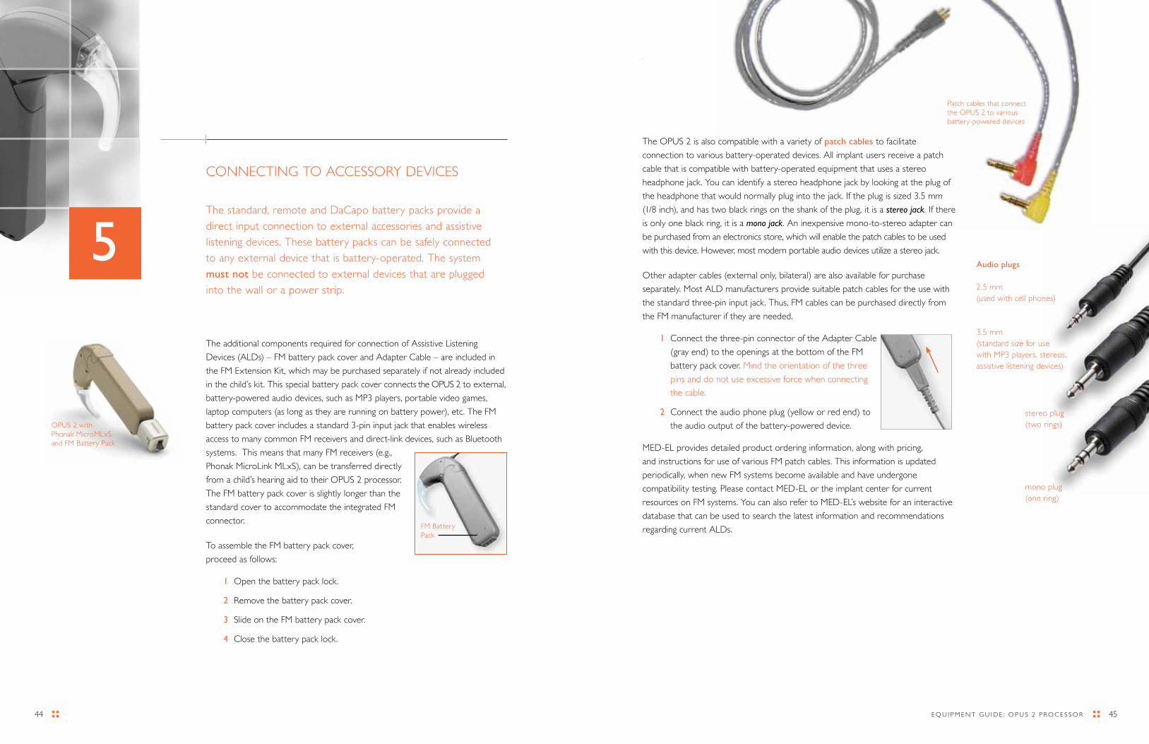
45E Q U I P M E N T G U I d E : O P U S 2 P r O C E S S O r 44
1
CONNECTING TO ACCESSOry dEVICES
The standard, remote and daCapo battery packs provide a direct input connection to external accessories and assistive listening devices. These battery packs can be safely connected to any external device that is battery-operated. The system must not be connected to external devices that are plugged into the wall or a power strip.
The additional components required for connection of Assistive Listening
devices (ALds) – FM battery pack cover and Adapter Cable – are included in
the FM Extension Kit, which may be purchased separately if not already included
in the child’s kit. This special battery pack cover connects the OPUS 2 to external,
battery-powered audio devices, such as MP3 players, portable video games,
laptop computers (as long as they are running on battery power), etc. The FM
battery pack cover includes a standard 3-pin input jack that enables wireless
access to many common FM receivers and direct-link devices, such as Bluetooth
systems. This means that many FM receivers (e.g.,
Phonak MicroLink MLxS), can be transferred directly
from a child’s hearing aid to their OPUS 2 processor.
The FM battery pack cover is slightly longer than the
standard cover to accommodate the integrated FM
connector.
To assemble the FM battery pack cover,
proceed as follows:
1 Open the battery pack lock.
2 remove the battery pack cover.
3 Slide on the FM battery pack cover.
4 Close the battery pack lock.
5
OPUS 2 with Phonak MicroMLxS and FM Battery Pack
FM Battery Pack
The OPUS 2 is also compatible with a variety of patch cables to facilitate
connection to various battery-operated devices. All implant users receive a patch
cable that is compatible with battery-operated equipment that uses a stereo
headphone jack. you can identify a stereo headphone jack by looking at the plug of
the headphone that would normally plug into the jack. If the plug is sized 3.5 mm
(1/8 inch), and has two black rings on the shank of the plug, it is a stereo jack. If there
is only one black ring, it is a mono jack. An inexpensive mono-to-stereo adapter can
be purchased from an electronics store, which will enable the patch cables to be used
with this device. However, most modern portable audio devices utilize a stereo jack.
Other adapter cables (external only, bilateral) are also available for purchase
separately. Most ALd manufacturers provide suitable patch cables for the use with
the standard three-pin input jack. Thus, FM cables can be purchased directly from
the FM manufacturer if they are needed.
1 Connect the three-pin connector of the Adapter Cable
(gray end) to the openings at the bottom of the FM
battery pack cover. Mind the orientation of the three
pins and do not use excessive force when connecting
the cable.
2 Connect the audio phone plug (yellow or red end) to
the audio output of the battery-powered device.
MEd-EL provides detailed product ordering information, along with pricing,
and instructions for use of various FM patch cables. This information is updated
periodically, when new FM systems become available and have undergone
compatibility testing. Please contact MEd-EL or the implant center for current
resources on FM systems. you can also refer to MEd-EL’s website for an interactive
database that can be used to search the latest information and recommendations
regarding current ALds.
Patch cables that connect the OPUS 2 to various battery-powered devices
Audio plugs
2.5 mm (used with cell phones)
3.5 mm (standard size for use with MP3 players, stereos, assistive listening devices)
mono plug (one ring)
stereo plug (two rings)

4746 E Q U I P M E N T G U I d E : O P U S 2 P r O C E S S O r
M I X I N G O P T I O N S
Mixing refers to the ability to combine the input from an assistive
listening device (such as an FM system) with the sound input from the
OPUS 2 processor. In general, mixing is almost universally preferred
over external input only, because it allows a child to monitor his or her
own voice. It also allows a child to hear the voices of other children in
the classroom through the processor, in addition to receiving the benefit
of the assistive device
For the standard and daCapo battery packs, the FM battery pack cover
allows a wireless connection. With wireless FM systems, the OPUS 2
will accept the mixing ratio that has been set on the FM receiver. If an
adapter cable is required, you can choose either a “mixing” or “non-
mixing” patch cable. Mixing cables allow the child to hear both signals,
with the input from the OPUS 2 microphone (environmental sound
and their own voice) mixed one-to-one along with the sound from the
external device. Non-mixing cables provide sound input only from the
external device. The patch cable included in the standard/FM Extension
kit is a mixing cable – a yellow plug with 3.5mm stereo jack. The non-
mixing cable is a red plug with 3.5mm stereo jack and is available for
purchase from MEd-EL.
With the TEMPO+ or OPUS 1 processor it was possible to reduce
the emphasis of the processor microphone signal (i.e. increase the
emphasis of the ALd) by reducing the Automatic Gain Control of the
processor. For the OPUS 2 if you want to increase the emphasis of the
ALd, increase or decrease the volume of the ALd or the ALd’s FM
gain settings. It is not possible to deactivate the OPUS 2 microphone
by reducing the Automatic Gain Control (AGC) only as reduction of
the AGC would reduce the signal of the ALd at the same time. It is
therefore required to use a “external-only” patch cable if you want to
deactivate the OPUS 2 microphone.
The remote battery pack has the mixing option built into the battery
pack. The sliding switch labeled “EXT/MIX” on the base of the battery
pack allows the user to choose whether to combine the OPUS 2
microphone input along with the external system (MIX) or simply listen
to the external system alone (EXT). If nothing is plugged into the direct
audio input port of the battery pack, the position of the sliding switch
has no effect.
W H E N T O U S E A C C E S S O r y d E V I C E S S U C H A S F M S y S T E M S
FM systems are assistive listening devices that help amplify and focus the child on the
teacher’s voice. The teacher wears a microphone and transmitter, and the child wears a
receiver that is connected to the processor. These “direct input” FM systems can be very
effective in improving the child’s ability to hear in a noisy environment and can successfully
reduce the effect of distance and reverberation between the speaker and listener. Each
FM system has different settings and connection capabilities. For specific information on
connecting a particular FM system to the processor, see current MEd-EL FM resources,
available from the company or an implant center.
Although direct input FM systems can be very helpful, they also have some drawbacks.
More equipment can sometimes mean more equipment to troubleshoot. Unfortunately,
the child is the only person who can truly indicate whether the sound quality through the
FM, coupled to the cochlear implant system, is acceptable. For this reason, we strongly
recommend that direct input FM systems be used only with children who are good at
reporting when equipment is or is not functioning normally. We also recommend that
the school audiologist or implant center verify the FM settings to ensure that speech
perception skills are at least as good while using the FM as they are without it.
In situations where the child is not a good reporter, a sound field system can be an
excellent solution. With these systems, the teacher wears a microphone and transmitter,
and the child sits next to a small desktop speaker. The problems of distance and
background noise are reduced, and the teacher can verify that the system is working
properly.
It is important to remember that when a child is listening through an FM system, they
are effectively connected auditorally to the teacher. In other words, the FM can be very
appropriate for teacher-directed activities or group lecture, but it is not effective (and
can actually degrade the learning experience) when the teacher is not the focal point.
For example, if the class is doing small-group work, where the teacher is moving from
group-to-group, it is not effective for the child to be listening to the teacher’s voice in
another group while trying to concentrate on his/her own group’s work. In addition, FM is
often unnecessary in one-on-one situations, such as speech-language or auditory therapy,
where distance and background noise are not a concern. Conscientious use of the FM
in appropriate situations can greatly assist a child; blanket use of the FM, without fully
understanding its advantages and disadvantages, may detract from the child’s ability to
make the most of the classroom environment.
CONNECTING TO ACCESSOry dEVICES
The remote battery pack has the mixing option built into the battery pack
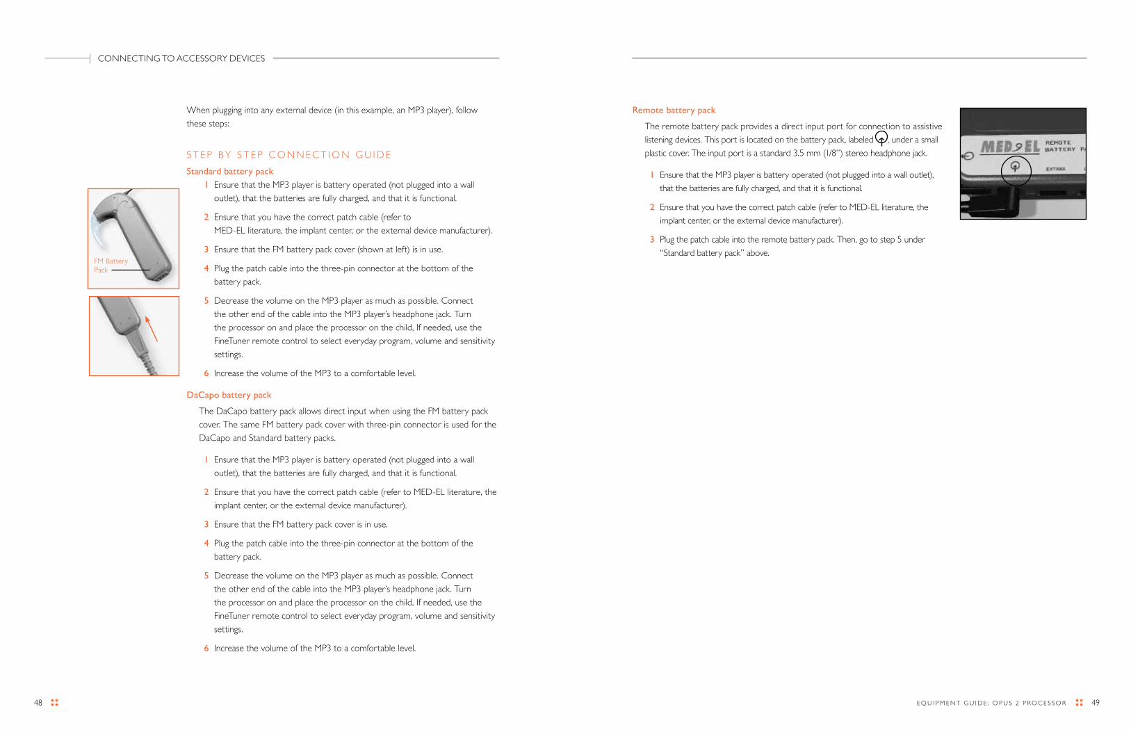
4948 E Q U I P M E N T G U I d E : O P U S 2 P r O C E S S O r
Remote battery pack
The remote battery pack provides a direct input port for connection to assistive
listening devices. This port is located on the battery pack, labeled , under a small
plastic cover. The input port is a standard 3.5 mm (1/8”) stereo headphone jack.
1 Ensure that the MP3 player is battery operated (not plugged into a wall outlet),
that the batteries are fully charged, and that it is functional.
2 Ensure that you have the correct patch cable (refer to MEd-EL literature, the
implant center, or the external device manufacturer).
3 Plug the patch cable into the remote battery pack. Then, go to step 5 under
“Standard battery pack” above.
When plugging into any external device (in this example, an MP3 player), follow
these steps:
S T E P B y S T E P C O N N E C T I O N G U I d E
Standard battery pack
1 Ensure that the MP3 player is battery operated (not plugged into a wall
outlet), that the batteries are fully charged, and that it is functional.
2 Ensure that you have the correct patch cable (refer to
MEd-EL literature, the implant center, or the external device manufacturer).
3 Ensure that the FM battery pack cover (shown at left) is in use.
4 Plug the patch cable into the three-pin connector at the bottom of the
battery pack.
5 decrease the volume on the MP3 player as much as possible. Connect
the other end of the cable into the MP3 player’s headphone jack. Turn
the processor on and place the processor on the child, If needed, use the
FineTuner remote control to select everyday program, volume and sensitivity
settings.
6 Increase the volume of the MP3 to a comfortable level.
DaCapo battery pack
The daCapo battery pack allows direct input when using the FM battery pack
cover. The same FM battery pack cover with three-pin connector is used for the
daCapo and Standard battery packs.
1 Ensure that the MP3 player is battery operated (not plugged into a wall
outlet), that the batteries are fully charged, and that it is functional.
2 Ensure that you have the correct patch cable (refer to MEd-EL literature, the
implant center, or the external device manufacturer).
3 Ensure that the FM battery pack cover is in use.
4 Plug the patch cable into the three-pin connector at the bottom of the
battery pack.
5 decrease the volume on the MP3 player as much as possible. Connect
the other end of the cable into the MP3 player’s headphone jack. Turn
the processor on and place the processor on the child, If needed, use the
FineTuner remote control to select everyday program, volume and sensitivity
settings.
6 Increase the volume of the MP3 to a comfortable level.
CONNECTING TO ACCESSOry dEVICES
FM Battery Pack
51E Q U I P M E N T G U I d E : O P U S 2 P r O C E S S O r 50
1
Auditory habilitation specialist :: This term is used in this handbook to refer
to the wide variety of professionals who become specialists in teaching deaf children
to use their residual hearing with hearing aids or cochlear implants.
It is well accepted that children with hearing loss need special assistance
to develop auditory skills. An auditory habilitation specialist can be a
speech-language pathologist, a teacher of the deaf/hard of hearing, a certified
auditory-verbal therapist, an audiologist – any one of a variety of related professions
– who has specialized in the habilitative aspect of hearing loss.
Auditory nerve Response Telemetry (ART™) :: This is a test done by the
audiologist that allows visual confirmation of the auditory nerve firing in response
to stimulation from the implant. The ArT measurement helps the clinician make a
“rough guess” as to the sound level required to trigger the auditory nerve; although
this measurement isn’t completely predictive of the levels he or she will need to set
in the child’s processor program, it does provide confirmation that stimulation levels
are roughly in the audible range for the child. ArT measurements can be helpful in
cases where a child cannot give adequate feedback during fitting sessions.
Automatic gain control (AGC) :: The AGC is a system the audio processor uses
to manage sounds of different loudness. The child with a cochlear implant does not
have a wide range of sound tolerance, as does a person with hearing. The AGC
ensures that very loud and very soft sounds are processed accurately so that they fit
into the range of hearing of the implant user.
BabyBTE™ :: A unique wearing option available with all MEd-EL audio processors
that allows the entire audio processor to be attached to the clothing for security.
Basal region :: The basal region of the cochlea is the high-pitched region. This is
the area that would be considered the base of the ‘snail shell’ shape, and is the area
closest to where sound first enters the inner ear.
Batteries :: MEd-EL audio processors are unique in that they have very long battery
life. Several pack configurations run on size 675 batteries (for an average battery life
of 3-5 days). These batteries can be purchased from MEd-EL or at many drugstores
and hearing aid dealers. It is critical that they are labeled as “high power” batteries.
Size 675 batteries that are not labeled “high power” will result in very short battery
life because their power levels fluctuate enough to signal a dead battery to the
processor, even though the batteries may be fully charged. The remote battery pack
uses one size AA battery (either rechargeable or alkaline).
GLOSSARy OF TERMS rELATEd TO MEd-EL COCHLEAr IMPLANT SySTEMS
Apical region :: The apical region is the tip of the ‘snail shell’ shape of the
cochlea. This region is responsible for sensing low-pitched sounds. MEd-EL
cochlear implants are the only implant systems that reach deep enough into the
cochlea to stimulate the apical region and the part of the system that is ‘tuned’
to low pitched sounds.
Audiogram :: The audiologist does an audiogram (sometimes called audiometry)
to determine the softest levels that a child can hear across low and high pitches.
Often, the audiologist will also assess how well the child perceives speech
sounds, which is called speech perception testing. Additionally, the audiologist
may measure how softly a child can understand speech.
Audiologist :: An audiologist is a specialist in the diagnosis and non-medical
treatment of hearing and balance problems. Audiologists obtain either a Master’s
or doctoral level degree, and then complete a training fellowship prior to
entering practice.
Audio processor :: A tiny wearable computer that transforms sound into
the coding understood by the implant. The TEMPO+ and OPUS 1 processor
contain a microphone, a sensitivity control, a program switch, and a volume
switch. The OPUS 2 contains a microphone and an on/off switch, with other
functions accessible through the FineTuner remote control unit. The processors
connect to different battery packs. The term “audio processor” is often used to
refer to the entire external part of the system (control unit, battery pack, coil and cable).
Auditory brainstem response testing (ABR) :: An audiologic test that roughly
measures hearing acuity without any participation from the child. As the child
sleeps, a clicking sound is presented to the ear, and the resulting brain activity is
measured. This measure is used extensively for diagnosing hearing problems in
infants and young children who are unable to respond behaviorally.
6
5352 E Q U I P M E N T G U I d E : O P U S 2 P r O C E S S O r
Decibels (dB) :: The decibel is the measure of a sound’s loudness. The range of
normal human hearing is typically 0-120 dB, with 0 dB being barely audible and 120
dB being barely tolerable. Conversational speech is fairly loud, at around 50 dB.
Detection :: An auditory response that indicates a sound was heard. A child might
indicate he or she detects a sound with a head turn, nodding, raising a hand, putting
a toy in a container, etc. The fact that a child detects a sound does not necessarily
mean he or she can discriminate it from other sounds – detection is simply an
indication of the presence or absence of a sound.
Diagnostic therapy :: diagnostic therapy refers to the process of using the therapy
environment to gain an understanding of a child’s level of speech, language or
auditory development. Through a series of fun activities, the auditory habilitation
specialist may attempt to determine how well the child is making use of hearing
through a hearing aid or an implant, without the use of formal test measures.
Direct input :: direct input refers to plugging an external sound source directly
into the audio processor using a patch cable. Any battery-operated device can be
connected to the MEd-EL audio processors.
Discrimination :: The ability of a child to understand a sound, word, or sentence.
Usually speech discrimination is measured by asking the child to point to various
objects or repeat various words or sentences.
Dynamic range :: A term used to define the loudness difference between the
softest sound a person can hear, and the loudest sound they can still comfortably
tolerate. The dynamic range of hearing is about 120 dB for most people with typical
hearing. The dynamic range of the implant user is about 30 dB. The Automatic
Sound Management system allows a sound range of 25-100 dB to be represented
accurately by the audio processor, giving the implant user an expanded input
dynamic range of 75 dB.
Earhook :: The earhook has a dual purpose: it holds the audio processor on the
ear, and in the case of the TEMPO+/OPUS 1, it connects the battery pack (or
battery pack cable) to the audio processor. The earhook can be ordered in a locking
configuration to keep a child from removing it.
Educational specialist :: In this guide, the term refers to a professional who
specializes in educating children with cochlear implants in a wide variety of
educational settings. This professional may provide advice and support to a child’s
educational team, or evaluate a child’s readiness for a certain type of educational
approach. The educational specialist could be a teacher of the deaf/hard of hearing,
an educational audiologist, or other related professional.
Battery pack :: A modular component of the audio processor that houses the
batteries that power the system.
Channel :: A channel refers to one of the 12 electrode pairs that are arranged along
the array. The channels are numbered consecutively, with channel 1 being the lowest
in pitch, and channel 12 being the highest in pitch. Not all children use all available
channels, however. Channels can be deactivated for various reasons without any
negative overall effect.
Coding strategy :: A coding strategy is a series of calculations used by the cochlear
implant system to measure the sound that is presented to the microphone, analyze
its components, and then determine which electrodes should be stimulated and how
they should be stimulated to best represent the original sound. Next, it generates a
code that is sent to the implanted portion of the system. This code tells the implant
which channel to stimulate within the cochlea, when to stimulate it, and how loud
that stimulation should be to accurately represent the sound at the microphone.
Coil :: The coil sends the coded information from the audio processor to
the internal implant. It uses radio signals to send this message across the skin.
The radio signals produced by the coil are a special frequency that is the only
frequency understood by the implant receiver. The coil also contains a magnet
that holds it against the correct area of the head so that it is aligned properly with
the implanted portion.
Coil cable :: The cable that connects the coil to the audio processor.
Control unit :: The computerized part of the audio processor that does the work of
transforming sound into a code that can be sent to the implant.
Connecting Piece :: A connection accessory that allows a battery pack to be
connected to the processor. All wearing options use some form of connecting piece;
in some configurations, the connecting piece may also be the earhook. A special
locking Connecting Piece safely locks the control unit and battery pack which keeps a
small child from removing it from the processor.
Communication methodology :: The form that communication (and education)
takes. Speaking, listening, using a signed or cueing system, or a complete signed
language are all various communication methodologies.
DaCapo System :: The daCapo rechargeable Battery System can be directly
connected to the control unit. The system makes the processor even lighter and
preserves the slim design. It is compatible with FM and other external devices. The
rechargeable battery cell provides 10-12 hours of continuous operation.
GLOSSAry OF TErMS

5554 E Q U I P M E N T G U I d E : O P U S 2 P r O C E S S O r
FM system :: An assistive device that consists of a microphone and transmitter worn by the speaker, and a receiver worn by the listener. In the case of the implant, the receiver must somehow connect to the audio processor with a patch cable, or with direct connection to the OPUS 2 FM battery cover. An FM system sends the speaker’s voice to the listener using FM radio waves to help overcome the problems of distance and background noise.
Hair cells :: The hair cells in the inner ear sense the pitch and intensity of sound waves that travel through the fluid of the inner ear. In most instances of deafness, the hair cells or some part of the anatomy associated with them do not function properly and cannot send signals accurately to the brain. The cochlear implant attempts to mimic the function of the hair cells by generating a signal similar to what the brain might normally receive from the inner ear.
Hertz (Hz) :: A measure of pitch that refers to the number of cycles per second that a sound causes oscillation. The range of human hearing is 20 Hz – 20,000 Hz. Speech information falls roughly in the frequency range 200 Hz – 6000 Hz. “Middle C” on the piano occurs at 262 Hz.
Implant :: The implanted portion of the system. The implant contains the receiver circuitry that decodes the signal from the coil, and also generates the tiny electrical pulses that travel down the electrode array and stimulate the cochlea. This receiver and stimulation circuitry is encased in a thin, and very strong package that sits just under the skin. The electrode array carries the electrical pulse from the implant case to the cochlea. The implant also contains a reference electrode that ensures the appropriate handling of electrical current. The implant contains a magnet, which attracts the external transmitting coil so that it is held in the correct place on the head.
Implant case :: The implanted electronics are hermetically sealed inside the case.
MEd-EL implants are the smallest implants available.
Individualized education plan (IEP) :: Although the IEP has a different name in
some states, the term refers to the formal educational plan that is developed for
each child who receives special services through a local school district. Federal law
requires that schools provide a “free and appropriate” education to all children,
including those with special needs. The IEP is a document that defines the services
that will be provided to meet that law. The IEP is developed with input from the
child’s parents, the child (when appropriate), teachers, school administrators and
special service providers.
Electrical auditory brainstem response testing (EABR) :: This is a method of
obtaining an ABr but using the sound generated by the implant. Because head
movement can obscure the response, children are often lightly sedated for the test.
This test assists in determining how well the auditory system is responding to the
stimulation generated by the implant.
Electrical stapedius reflex test (ESRT) :: An objective measure that can be useful
in establishing an MCL measurement in children who are unable to provide feedback
to the audiologist about the loudness of sound. A small probe is placed in the opposite
ear. The stimulation level of the implant is increased until a small muscle reflex is seen in the
opposite ear. This muscle reflex is present in most people, and occurs at a level that is loud,
but still comfortable. The level at which this reflex occurs correlates well with the MCL level of
the map.
Electrode array :: The implanted device has a long, flexible portion that is inserted
into the cochlea through a small opening. This portion of the device is called the
electrode array.
Electrode contacts :: Electrode contacts are small oval-shaped disks made of
platinum that are arranged along the electrode array. In MEd-EL implants, they are
arranged in 12 pairs. Each pair stimulates a different frequency region in the cochlea.
Electrostatic discharge (ESD) or static electricity :: A build-up of charge
difference between a person and an object, often caused by friction between
synthetic materials, or electronic equipment (such as TV screens), usually felt as a
“shock” when the statically charged person touches a grounded object. The cochlear
implant user does not feel the “shock” any differently from a non-user. A good example is
the shock that occurs when touching a light switch after walking on the carpet. ESd tends
to be worse in a dry environment. ESd can cause damage to electronic equipment of all
kinds. MEd-EL audio processors have built-in safeguards to protect the processor from
program loss due to ESd.
Expressive language :: The ability of the child to produce language to communicate
with others.
FineTuner :: The FineTuner is the remote control device for use with the OPUS 2
processor. It is used for changing sensitivity, volume and program settings.
Fixation device :: A small accessory that is attached to the battery pack that allows it to be
connected to the clothing. The fixation bar can accommodate a small safety pin or diaper
pin. The fixation clip can be clipped directly to clothing.
GLOSSAry OF TErMS
5756 E Q U I P M E N T G U I d E : O P U S 2 P r O C E S S O r
Mixing cables :: “Mixing” refers to a feature of certain assistive listening devices
(such as FM systems) that allows the user to combine the signal from the speaker
with the signal from the audio processor microphone. The processors support this
feature, but it is necessary to ensure that a mixing patch cable is in use.
Most comfortable loudness (MCL) :: MCL refers to a loudness level that is loud,
but still comfortable, to the listener. This is an important measurement made on
each channel during a mapping session. The final MCL setting of the map sets an
upper limit for loudness, and stimulation will never exceed that limit. MCL levels are
different for each user; therefore it is important that audio processors are never
traded between users.
MRI scan :: Magnetic resonance Imaging is a medical diagnostic procedure.
At the time of printing, MEd-EL cochlear implants are FdA approved for 0.2T (Tesla)
MrI scanners without the removal of the implant’s internal magnet. Only machines
of 0.2T strength should be utilized with MEd-EL at this time. Additional factors,
such as head placement, make it important for the scanning radiologist to contact
MEd-EL prior to scheduling the MrI scan.
Newborn hearing screening :: A program in place in many hospitals that allows a
child’s hearing to be evaluated immediately after the baby is born.
ON/OFF switch :: The ON/OFF switch is located on each of the TEMPO+ and
OPUS 1 battery packs. The battery pack lock functions as the ON/OFF switch for
the OPUS 2.
Otologist/Neurotologist :: An otologist is a physician who first became an ear,
nose and throat specialist, and then went on to specialize in just the ears and
the area of the head surrounding the ear. An otologist completes over 10 years
of medical training and a specialized otology training fellowship prior to entering
practice.
Outer ear :: The anatomical portion of the hearing system that includes the pinna
(the visible “ear” on the outside of the head), the ear canal, and the eardrum
(tympanic membrane).
Phoneme :: The smallest unit in a language that is capable of conveying a change in
meaning. For example, the m in mat and the b in bat. There are 41 phonemes in the
English language
Phonemic repertoire :: The range of various phonemes (speech sounds) that a
child is able to produce. Generally, certain speech sounds seem to develop earlier
than others over a period of several years.
Inner ear :: The anatomical portion of the hearing system that triggers nerve
impulses that travel to the brain. Both the hearing and balance systems are found in
the inner ear. The cochlea is a small snail-shaped structure that contains the tiny hair
cells that sense sound and send signals to the auditory nerve. The semicircular canals
sense balance and position changes and report these changes to the brain.
Input dynamic range (IDR) :: See dynamic range. The Idr is a measure of the
implant system’s ability to handle a wide range of sound inputs accurately. The Idr of
the MEd-EL system is 75 dB.
LED indicator :: The small red light on the front of the processor will flash in a
variety of blinking patterns to indicate different status or error conditions of the
processor or batteries.
Localize :: The act of locating the source of a sound.
Magnet :: There are two magnets in the system: one in the coil and the other in the
implant case. Together the two hold the coil in place on the head. The implant center
audiologist can adjust the magnetic strength of the coil.
Map :: The program stored in the audio processor that tells the system how to
process sound on each channel so that it is most audible and comfortable for
the individual user. Each implant user’s map varies considerably from every other
user. Maps also change over time, as the human body also fluctuates slightly in its
sensitivity to electrical stimulation over time.
Mapping sessions :: A visit to the implant center where the individual’s audio
processor program is evaluated and changed if necessary
Mastoid bone :: The area of bone directly behind the ear where the implanted
portion of the system is placed.
Microphone port :: The tiny opening on the front corner of the processor is the
microphone port.
Microphone test device (MTD) :: An optional accessory that allows a hearing
person to listen to the microphone of the processor to determine whether it is
functioning adequately.
Middle ear :: The anatomical portion of the ear just beyond the eardrum. The
middle ear consists of a small air space that holds the three small bones of hearing
(malleus, incus and stapes). The Eustachian tube allows air exchange between the
middle ear air space and the outside; when the ears ‘pop’ during a change in altitude,
this is actually the pressure equalizing between the middle ear and the outside. The
middle ear is the most common site of an ear infection.
GLOSSAry OF TErMS
5958 E Q U I P M E N T G U I d E : O P U S 2 P r O C E S S O r
Speech-language pathologist :: A speech language pathologist is a specialist in the
diagnosis and non-medical treatment of speech and language disorders. An SLP
obtains either a Master’s or doctoral level degree, and then completes a training
fellowship prior to entering practice.
Steady state evoked potentials :: An objective measure of hearing that requires
no participation from the child. SSEP’s provide detailed information about the
child’s hearing acuity. This is a very new measure that does not yet have widespread
availability.
Suprasegmental :: The cues of language that come from pitch, intensity and
durational differences in the pattern of speech. Suprasegmentals are what allow an
English speaker to recognize the inflection of a question, even though the question is
asked in another language.
Telecoil :: The OPUS 2 has an integrated telecoil. The telecoil picks up magnetic
sound signals coming from telephone receivers or loop systems which are installed in
some public buildings, allowing another option for hearing on the phone or receiving
input from assistive devices.
Telemetry :: A feature built into the implant system that allows the audiologist to
test the function of the implanted portion of the system. This is a quick test that
requires no input from the child, and provides valuable information about how well
the electrodes are functioning.
Threshold :: Hearing threshold is defined as the level at which a person hears a
sound 50% of the time. This means it is so soft, that the listener isn’t even sure the
sound is really there. When the audiologist performs an audiogram, he or she is
trying to find the child’s threshold of hearing at different pitches across a spectrum
from low to high pitch. Threshold can also refer to the softest level of electrical
stimulation a child can perceive. In the MEd-EL mapping software, the threshold
setting of the map is abbreviated as “THr.” However, with MEd-EL cochlear
implants, threshold is defined as a level below the level where the patient perceives
a sound. Threshold measures do not significantly impact the quality of the resulting
map, and often are not measured.
Tonotopic organization :: The inner ear and the auditory area of the brain and
central nervous system are arranged in pitch order, from low to high. Sounds of
different pitches are processed by different hair cells, nerve fibers, or brain synapses.
The cochlear implant, therefore, is designed to present pitch information to the areas
of the cochlea that are “tuned” to be sensitive to those pitches.
Play audiometry :: An audiometric technique that teaches a young child to complete
an activity when a sound is heard (such as dropping a block into a container or
putting a piece in a puzzle). This facilitates testing the hearing of preschoolers and
toddlers.
Program switch :: The program switch on the TEMPO+ and OPUS 1 allows
the user to select different programs, or maps. The FineTuner is used to change
programs for the OPUS 2 audio processor. Please refer to the implant center
audiologist or parent to determine which program should be used most of the time.
Receptive language :: The ability of the child to understand language that is
presented to him/her.
Residual hearing :: This is the term used to describe the hearing that remains after a
hearing loss occurs. Most people with significant hearing loss still have some residual
hearing that can be stimulated by amplifying sound using a hearing aid. However, the
remaining hearing often does not provide enough clarity for a hearing aid to be of
much benefit. These are the individuals who are candidates for cochlear implantation.
Sensitivity control :: The sensitivity control determines how sensitive the
microphone is. High sensitivity settings cause the microphone gain to
be increased. This can be good in a quiet environment, but in a noisy environment, it
results in poor loudness relationships between soft and
loud sounds. The general “rule of thumb” is to keep the sensitivity setting
at about half-way on.
Sound field FM system :: An FM system that does not plug into the audio processor.
Instead, a small speaker near the listener amplifies the speaker’s voice. A sound field
system is a good alternative to regular FM if the child is unable to provide feedback
on the quality of a direct FM connection.
Speech awareness threshold (SAT) :: The softest level at which a child can detect
a spoken word. However, the child is not required to be able to understand the
spoken word.
Speech reception threshold (SRT) :: The softest level at which a child can hear a
spoken word well enough to repeat it back correctly.
GLOSSAry OF TErMS
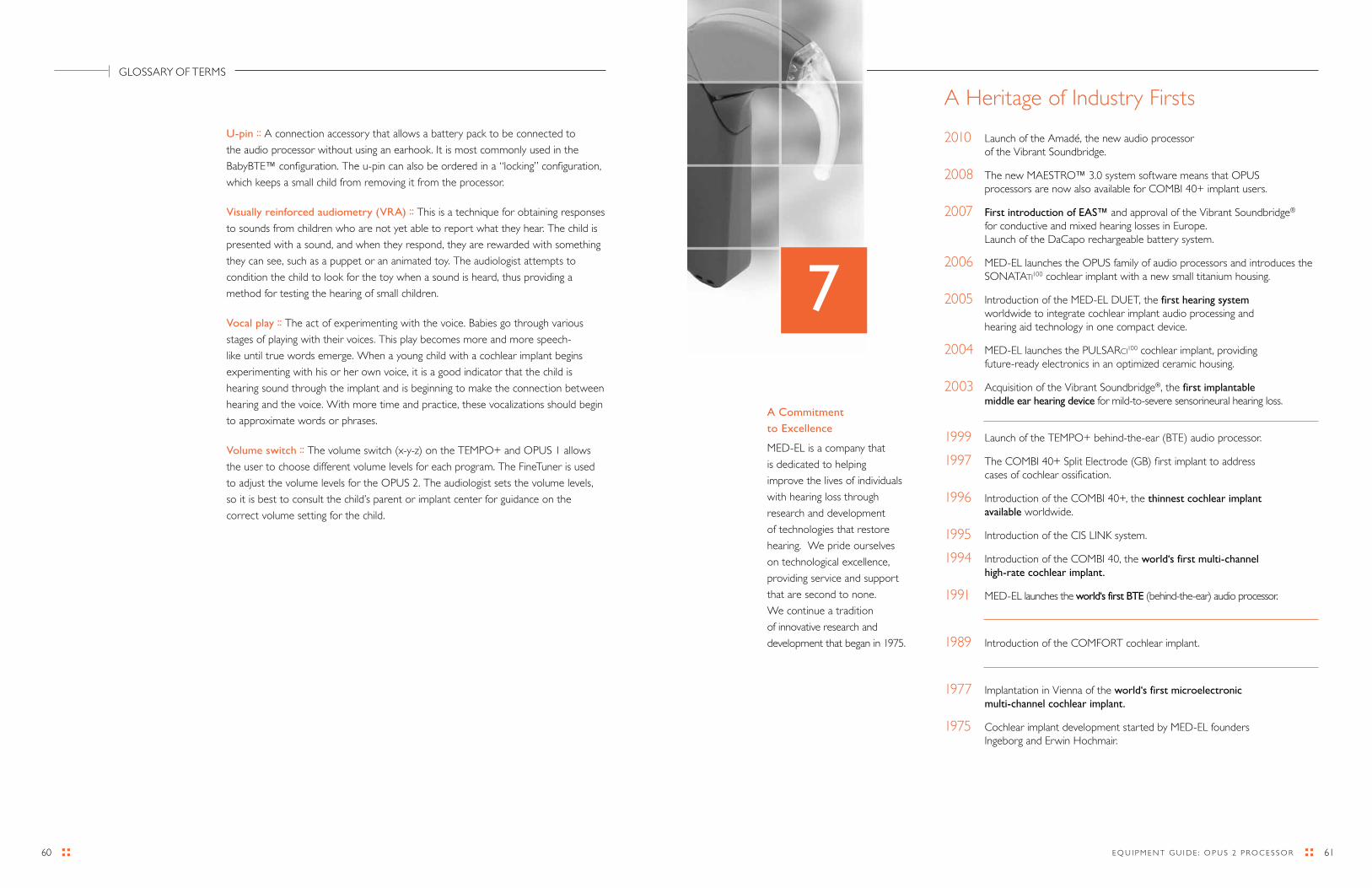
6160 E Q U I P M E N T G U I d E : O P U S 2 P r O C E S S O r
U-pin :: A connection accessory that allows a battery pack to be connected to
the audio processor without using an earhook. It is most commonly used in the
BabyBTE™ configuration. The u-pin can also be ordered in a “locking” configuration,
which keeps a small child from removing it from the processor.
Visually reinforced audiometry (VRA) :: This is a technique for obtaining responses
to sounds from children who are not yet able to report what they hear. The child is
presented with a sound, and when they respond, they are rewarded with something
they can see, such as a puppet or an animated toy. The audiologist attempts to
condition the child to look for the toy when a sound is heard, thus providing a
method for testing the hearing of small children.
Vocal play :: The act of experimenting with the voice. Babies go through various
stages of playing with their voices. This play becomes more and more speech-
like until true words emerge. When a young child with a cochlear implant begins
experimenting with his or her own voice, it is a good indicator that the child is
hearing sound through the implant and is beginning to make the connection between
hearing and the voice. With more time and practice, these vocalizations should begin
to approximate words or phrases.
Volume switch :: The volume switch (x-y-z) on the TEMPO+ and OPUS 1 allows
the user to choose different volume levels for each program. The FineTuner is used
to adjust the volume levels for the OPUS 2. The audiologist sets the volume levels,
so it is best to consult the child’s parent or implant center for guidance on the
correct volume setting for the child.
A Commitment
to Excellence
MEd-EL is a company that
is dedicated to helping
improve the lives of individuals
with hearing loss through
research and development
of technologies that restore
hearing. We pride ourselves
on technological excellence,
providing service and support
that are second to none.
We continue a tradition
of innovative research and
development that began in 1975.
7
GLOSSAry OF TErMS
A Heritage of Industry Firsts
2010 Launch of the Amadé, the new audio processor of the Vibrant Soundbridge.
2008 The new MAESTrO™ 3.0 system software means that OPUS processors are now also available for COMBI 40+ implant users.
2007 First introduction of EAS™ and approval of the Vibrant Soundbridge® for conductive and mixed hearing losses in Europe. Launch of the daCapo rechargeable battery system.
2006 MEd-EL launches the OPUS family of audio processors and introduces the SONATATI100 cochlear implant with a new small titanium housing.
2005 Introduction of the MEd-EL dUET, the first hearing system worldwide to integrate cochlear implant audio processing and hearing aid technology in one compact device.
2004 MEd-EL launches the PULSArCI100 cochlear implant, providing future-ready electronics in an optimized ceramic housing.
2003 Acquisition of the Vibrant Soundbridge®, the first implantable middle ear hearing device for mild-to-severe sensorineural hearing loss.
1999 Launch of the TEMPO+ behind-the-ear (BTE) audio processor.
1997 The COMBI 40+ Split Electrode (GB) first implant to address cases of cochlear ossification.
1996 Introduction of the COMBI 40+, the thinnest cochlear implant available worldwide.
1995 Introduction of the CIS LINK system.
1994 Introduction of the COMBI 40, the world‘s first multi-channel high-rate cochlear implant.
1991 MEd-EL launches the world‘s first BTE (behind-the-ear) audio processor.
1989 Introduction of the COMFOrT cochlear implant.
1977 Implantation in Vienna of the world‘s first microelectronic multi-channel cochlear implant.
1975 Cochlear implant development started by MEd-EL founders Ingeborg and Erwin Hochmair.

BrIdGE is a program for education and rehabilitation professionals developed by MEd-EL.
For more information about BrIdGE products, please visit www.medel.com.
2288
7 r1
.0
©20
11 M
Ed-E
L C
Or
POr
AT
ION
MED-EL Corporation, North America MED-EL Worldwide Headquarters 2511 Old Cornwallis road Fürstenweg 77a Suite 100 A-6020 Innsbruck durham, NC 27713 Austria tel/tdd (919) 572-2222 tel +43-512-28 88 89fax (919) 484-9229 fax +43-512-29 33 81toll free (888) MEdEL-CI (633-3524) email [email protected]
www.medel.com