equipment installation manual - dac...
TRANSCRIPT

Equipment Installation Manual
1049-2510-01 Y.doc
1049-2510-01
Rev Y
Page 1 of 85
EQUIPMENT INSTALLATION MANUAL
For the
GDC31 ROLL STEERING CONVERTER
P/N 1049-4000-XX-001( )
Rev Y April 5, 2017
DAC International
6702 McNeil Drive
Austin, TX 78729
Copyright 2017, DAC International. All rights reserved.

Equipment Installation Manual
1049-2510-01 Y.doc
1049-2510-01
Rev Y
Page 2 of 85
RECORD OF REVISIONS
REV DESCRIPTION DATE APPROVED
IR INITIAL RELEASE E266 4-5-04 LW
A Correct P/N of mating connector E269 4/8/04 LW
B CHANGED BREAKER TO 2 AMPS E272-04 4/19/04 LW
C Reduced 28V and 14V install kits into one universal kit
and added instructions for configuration. Added wiring
diagram for Bonanza A-36. E306
7/26/04 LW
D Omit approval pending E321 9/17/04 LW
E Add numerous wiring diagrams E327 10/22/04 LW
F Add additional wiring diagrams, correct table 4 E389 3/30/05 LW
G Add lighting bus circuit diagram to all wiring diagrams.
Omit jumper on drawings Fig. 9 & 11.
Add note to installation section, page 16. E415
5/20/05 CC
H Add Reference page for lighting connections and correct
drawings. Add KLN-94 incompatibility stmt to Operation
Overview and Appendix A. Correct pin references on
ARINC HSI drawings. Remove Isolation Coupler from
Fig. 10. Add –03 model & update all applicable sections
and drawings. Add Isolation Coupler to Figure 4 drawing.
Add Follow-on Installation Data form and instructions.
E432
10/5/05 LW
I Add FD112 and AP107 drawing. E461
Delete 1049-4200-10 kit information.
Edit drawings to reflect –03 vs –01 differences
11/16/05 CC
J Correct typo on Figure 3 ARINC HSI with Century IV
drawing; Add Isolation Coupler requirement statement to
“OPTIONAL EQUIPMENT” section;
2/21/06 LW
K Add various drawings; minor changes on misc drawings;
added Appendix D, GPS Receiver interconnect to
RS232/ARINC 429; Added STC Permission Stmt E645
12/12/06 LW
L Added various drawings; Added gain jumper flag note to
various King autopilot drawings; Corrected pin-out on
6/8/07 LW

Equipment Installation Manual
1049-2510-01 Y.doc
1049-2510-01
Rev Y
Page 3 of 85
REV DESCRIPTION DATE APPROVED
various STEC drawings; Add note to Appendix C. Add
Note: “This A/P is not STC’d” on all relevant drwgs.
Fig 2 – Add Note:
Fig 4 – Remove AP-Offset line
– Add jumper b/t pin 10 & 11 – GainSel 1
– Add pin 16 to J2 – 400hz Rtn
Fig 8 – Add lines b/t DG and Iso Coupler and pin info for
52D54 Exc
Fig 19 – Change jumper for GainSel2 to dotted line and
add flag note: “If turn is sluggish, install this jumper”.
Fig 20 – Add line between pin 13 of AP Comp and pin 15
of GDC31
– Add KCP 299 pins and dotted lines
Fig 26 – Add Iso Coupler to prevent voltage spike to Roll
Computer when setting breaker.
Fig 28 – Add STEC 30 Pinout E729
M Added various drawings; Revised website link on pg 26;
Added KLN-89A to Operation Note Appendix A Note as
non-compatible with the GDC31.
Fig 7 - Revised wiring illustrations.
Fig 13 - Add 5kz flag note.
Fig 20 - Remove Type Sel jumper & added jumper to
Phase Sel.
Fig 31 - Add Type Sel jumper.
Fig 32 – Add Phase Sel.
12/06/07 LW
N Added paragraph to PMA Section, pg 8.
Removed Installation Manual from kit part list, pg 9.
Added paragraph to Installation Section, pg 16.
Added paragraph to Environmental Section, pg 29.
Revised Figure 2, Pg 41, Relay Interconnect Diagram.
Fig 17, Pg 60 - Add KC-295 computer for KFC200
autopilot & ground shield at pin 6 & 15 of GDC31.
Fig 23, Pg 66 – Removed jumper from pins 11 & 23.
Removed non-STC’d drawings
Added additional wiring diagrams (Fig 2, 14, 16, 18, 19,
25, 26, 29, 32, 33, & 34). E1286
08/01/2011 BH
P Added ARC800 with IG-895A / NSD-360 / NSD-1000
drawing & Century 2000 drawings. E1299
08/15/2011 BH

Equipment Installation Manual
1049-2510-01 Y.doc
1049-2510-01
Rev Y
Page 4 of 85
REV DESCRIPTION DATE APPROVED
R Added KAP150 with KI525A drawing E1350 12/08/2011 BH
S Delete S-TEC 50/55/60/65 (DC) with S-TEC 6406.
Revised S-TEC 50 (AC) with 6406 HSI drawing to include
S-TEC 55/60/65 autopilots. Added STC Pending
statement to ARC300/800, Century 2000 and KAP 140
drawings. E1735
10/28/2013 BH
T Corrected EXC pin reference on SN3500 P2 on Figure 13
drawing E1750.
12/16/2013 BH
U Revised Century II or III with 52D54 drawing to change
pins D & E at CD33 (Pigtail) from C & F at CD33 (Fixed).
Changed labels to DG Exc 5 KHz from Roll Exc 5 KHz.
Reworded flag notes for clarity on all drawings. Added
flag note to ground all shielded wiring on drawings in Fig
8-12, 28, 38, 39, 41 & 42. Added drawing for KCS55
System with KG-102A & SN3308 / SN3500. Removed
ARC 300, ARC 800, Century 2000 & KAP140 drawings.
001A software version not supported.
E1856
05/22/2015 BH
V Reworded “Required Equipment” header and first sentence
on page 10. Reworded last sentence in “Optional
Equipment” paragraph on page 11. Added ARC 300 (Fig
2-3), ARC 800 (Fig 7), Century 2000 (Fig 8-11) and KAP
140 (fig 21-22) drawings E1876
10/06/2015 BH
W Edited jumper on drawing KING KAP 140 w/ KI-525A at
GDC31 pin 11 to pin 21 and flag notes relative to change.
Inserted Century II/III with NSD-360A / NSD-1000 to
1C388-2 Radio Coupler drawing.
Renumbered pages. Edited various drawing notes.
E1891
03/10/16 BH
X Remove page 29 ( GDC31 STC permission statement)
renumber pages E1893
03/22/16 BH
Y Add Collins AP-105 drawing 04/05/17 BH

Equipment Installation Manual
1049-2510-01 Y.doc
1049-2510-01
Rev Y
Page 5 of 85
Table of Contents
RECORD OF REVISIONS ........................................................................................................................... 2 INTRODUCTION: ........................................................................................................................................ 8
DESCRIPTION: ............................................................................................................................................. 8 PART NUMBERS: ........................................................................................................................................ 9 REGULATORY COMPLIANCE:................................................................................................................. 9
Software ..................................................................................................................................................... 9 PMA ........................................................................................................................................................... 9
Environmental ............................................................................................................................................ 9 REQUIRED EQUIPMENT ......................................................................................................................... 10 OPTIONAL EQUIPMENT .......................................................................................................................... 11
SPECIFICATIONS: ..................................................................................................................................... 12 Physical: ................................................................................................................................................... 12 Electrical: ................................................................................................................................................. 12
Serial Data Input: ..................................................................................................................................... 12 ARINC 429 Input: (-03 Only) ................................................................................................................. 13
Roll Sum Steering Output: ....................................................................................................................... 13 Reference Inputs: ..................................................................................................................................... 13 AP Offset Input: ....................................................................................................................................... 14
Annunciator Output:................................................................................................................................. 14 Flag Input: ................................................................................................................................................ 14
Certification: ............................................................................................................................................ 14 Reliability: ................................................................................................................................................ 14
OPERATION: .............................................................................................................................................. 15
Overview .................................................................................................................................................. 15
Analog Output .......................................................................................................................................... 15 Reference Inputs (Excitation) .................................................................................................................. 15 ARINC 429 Input ..................................................................................................................................... 15
GPS Mode Annunciator Control .............................................................................................................. 16 Super Flag Input ....................................................................................................................................... 16
INSTALLATION ......................................................................................................................................... 17 Material Not Supplied .............................................................................................................................. 17
Special Tools ............................................................................................................................................ 17 Mounting Considerations ......................................................................................................................... 18 Wiring Considerations ............................................................................................................................. 18 Pre Modification Planning ....................................................................................................................... 19 Equipment Interfaces ............................................................................................................................... 19
Installation Summary ............................................................................................................................... 19 Steering Output Scale Factor Determination ........................................................................................... 20
Configuration Pins ................................................................................................................................... 21 Gain Settings Using Ref 1 input J1-18 ..................................................................................................... 21 Gain Settings Using Ref 2 input J1-6 ....................................................................................................... 21

Equipment Installation Manual
1049-2510-01 Y.doc
1049-2510-01
Rev Y
Page 6 of 85
Phase Selection ........................................................................................................................................ 22 Position/Rate Selection ............................................................................................................................ 23 Baud Rate Selection ................................................................................................................................. 23 GPS Receiver Setup ................................................................................................................................. 23
REMOVAL AND REPLACEMENT .......................................................................................................... 24 Removal, GDC31 ..................................................................................................................................... 24 Replacement, GDC31 .............................................................................................................................. 24 Removal, Mode Annunciator ................................................................................................................... 24 Replacement, Mode Annunciator ............................................................................................................ 24
EQUIPMENT CHECKOUT ........................................................................................................................ 25 Ground Functional Test............................................................................................................................ 25 Flight Functional Test .............................................................................................................................. 25
CONTINUED AIRWORTHINESS: ............................................................................................................ 27 INSTRUCTIONS TO COMPLETE FOLLOW-ON INSTALLATION DATA FORM: ............................ 27 FOLLOW-ON INSTALLATION DATA FORM ....................................................................................... 28
CONNECTOR PIN OUT: (1049-4000-03) ................................................................................................ 30 OUTLINE DRAWINGS .............................................................................................................................. 31
GDC31 Outline ........................................................................................................................................ 31 Switch / Annunciator Outline .................................................................................................................. 32 Isolation Coupler Outline ......................................................................................................................... 33
SLIDE LATCH ASSEMBLY ...................................................................................................................... 34 APPENDIX A – RS232 AVIATION FORMAT ......................................................................................... 35
APPENDIX B – ARINC 429 INPUT .......................................................................................................... 37 Label 121 - Bank Angle Command ......................................................................................................... 37
APPENDIX C – GPS RECEIVER INTERCONNECT ............................................................................... 38
Figure 1 RS232 Interconnect Diagram .................................................................................................. 38
Figure 2 ARINC 429 Interconnect Diagram .......................................................................................... 38 APPENDIX D - OPTIONAL LIGHTING CONTROLS ............................................................................ 39
Figure 1 Day / Night Switch Interconnect Diagram .............................................................................. 39
Figure 2 Relay Interconnect Diagram .................................................................................................... 39 APPENDIX E - TYPICAL INTERCONNECT ........................................................................................... 40
Figure 1 - TYPICAL INTERCONNECT................................................................................................ 41 Figure 2 - ARC 300A with G502A ......................................................................................................... 42
Figure 3 - ARC 300A (DC) with NSD-360 ............................................................................................ 43 Figure 4 - ARC 400/S530A with PN 101 ............................................................................................... 44 Figure 5 - ARC 400B/CA-550A/FD (10VAC) with G502A .................................................................. 45 Figure 6 - ARC 400B/CA-550A/FD (DC) with NSD-360 ..................................................................... 46 Figure 7 - ARC 800B/CA-550A/FD with IG-895A / NSD-360 / NSD-1000 ......................................... 47
Figure 8 - CENTURY 2000 with 52D254 .............................................................................................. 48 Figure 9 - CENTURY 2000 with FD112V ............................................................................................. 49
Figure 10 - CENTURY 2000 with IG-832A / NSD-360 / NSD-1000 .................................................... 50 Figure 11 - CENTURY 2000 with KI-525A ........................................................................................... 51 Figure 12 - CENTURY II or III with 52D54 to 1C388/M/P Radio Coupler .......................................... 52
Equipment Installation Manual
1049-2510-01 Y.doc
1049-2510-01
Rev Y
Page 7 of 85
Figure 13 - CENTURY II / III with 4000C DG / 52D54 to 1C385 / 1D395 Console / Amp ................. 53 Figure 14 - CENTURY II / III with ARINC HSI to 1C385 / 1D395 Console/Amp .............................. 54 Figure 15 - CENTURY II / III with IN-831A HSI to 1C385 / 1D395 CONSOLE/AMP ...................... 55 Figure 16 - CENTURY II / III with NSD-360A / NSD-1000 to 1C388-2 Radio Coupler ..................... 56
Figure 17 - CENTURY II / III with NSD-360A / NSD-1000 to 1C385 / 1D395 CONSOLE/AMP ...... 57 Figure 18 - CENTURY III with SN3308 / SN3500 to 1C388-2 Radio Coupler .................................... 58 Figure 19 - CENTURY IV with ARINC HSI ......................................................................................... 59 Figure 20 - CENTURY IV with IG-832A / NSD-360 / NSD-1000........................................................ 60 Figure 21 - COLLINS AP105 with 331A-6R ......................................................................................... 61
Figure 22 - COLLINS AP106 with FD112C/V ...................................................................................... 62 Figure 23 - KING KAP 140 with 4000C-15 DG .................................................................................... 63 Figure 24 - KING KAP 140 with KI-525A ............................................................................................ 64
Figure 25 - KING KCS55 SYSTEM with KI-525 / 525A and KA-52 / KA-57 ..................................... 65 Figure 26 - KING KCS55 SYSTEM with KG-102A & SN3308 / SN3500 HSI ................................... 66 Figure 27 - KING KFC 150 with EFIS 50 .............................................................................................. 67
Figure 28 - KING KFC 150 with KI-525A ............................................................................................. 68 Figure 29 - KING KFC 150 with SN3308 / SN3500 & KG-102A ......................................................... 69
Figure 30 - KING KFC 200 / 300 Series with KI-525A ......................................................................... 70 Figure 31 - KING KFC 200 with KA-118 & KPI-550A ........................................................................ 71 Figure 32 - KING KFC 200 with KI-825 HSI ........................................................................................ 72
Figure 33 - KING KFC 200 / 300 Series with KPI-552 ......................................................................... 73 Figure 34 - KING KFC 200 Series with SN3308 / SN3500 & KG-102A .............................................. 74
Figure 35 - KING KFC 200 Series with SN3308 / SN3500 – without DG ............................................ 75 Figure 36 - KING KFC 325 with EFIS 50 .............................................................................................. 76 Figure 37 - S-TEC 50/55/60/65 (DC) with NSD-360A / NSD-1000 ...................................................... 77
Figure 38 - S-TEC 50/55/55X/60/65 (AC) with 6406 HSI ..................................................................... 78
Figure 39 - S-TEC 50/55/60 with KI-525A ............................................................................................ 79 Figure 40 - S-TEC 50/55/60/65 with ARINC HSI .................................................................................. 80 Figure 41 - S-TEC 50/60/65 (AC) with 1U262-006-45 DG .................................................................. 81
Figure 42 - S-TEC 50/60/65 (AC) with 52D54 DG ................................................................................ 82 Figure 43 - S-TEC 55 (DC) with 52D54DG ........................................................................................... 83 Figure 44 - S-TEC 55/65 (AC) with 6443 HSI ....................................................................................... 84 Figure 45 - S-TEC 60 with G502A HSI .................................................................................................. 85

Equipment Installation Manual
1049-2510-01 Y.doc
1049-2510-01
Rev Y
Page 8 of 85
INTRODUCTION:
This Installation Manual contains installation data, specifications and Instructions for Continued
Airworthiness for the DAC International Model GDC31 Roll Steering Converter, Part Number 1049-4000-
XX-001( ). Check the DAC International website www.dacint.com/gdc31 regularly for updates to this
manual or for additional information.
DESCRIPTION:
The GDC31 Roll Steering Converter with software version 001A is designed to receive RS232 or RS422
serial data from a GPS Navigation System to produce both an analog Roll Sum Steering (RSS) signal and
ARINC 429 labels bank angle command and ground speed. The GDC31 Roll Steering Converter with
software version 001B is designed to receive RS232 or RS422 serial data or ARINC 429 Label 121 from a
GPS Navigation System to produce an analog Roll Sum Steering (RSS) signal.
The GDC31 output signal connects to the heading error input of the aircraft’s existing autopilot. The
GDC31 mimics the heading error signal of the aircraft’s installed HSI or DG. The GDC31 does not reduce
or otherwise alter any existing safety features of the autopilot, such as bank limiting, rate limiting and
protection from a hard over. The GDC31 provides lateral (roll) data only (no pitch data is supplied by the
GDC31).
The pilot simply selects between heading mode and GPS mode using the supplied switch / annunciator. In
heading mode, the autopilot operates as always, tracking the heading bug of the HSI or DG. In GPS mode,
the GDC31 RSS signal drives the autopilot’s heading channel. The GDC31 calculates the correct course
intercept angle from the data supplied by the GPS, smoothly guiding the aircraft onto the course. The
GDC31 then holds the aircraft on the selected course. If the GPS is programmed with Flight Plan data, the
GDC31 will calculate the new intercept angle at each waypoint change, intercepting and holding the new
course without pilot intervention.
The GDC31 is designed to operate with both rate based and position based autopilots.
SERIAL / FLAG
HDG ERROR
ARINC 429 IN
GPS
HSI / CDI
(-03 Only)
AUTOPILOT
GDC31 RSC
ROLL STEERING
HDG
GPS
ANNUN / SW
HDG ERROR

Equipment Installation Manual
1049-2510-01 Y.doc
1049-2510-01
Rev Y
Page 9 of 85
PART NUMBERS:
The GDC31 Data Converter is available under the following part number:
1049-4000-03-001B GDC31 Roll Steering Converter, with RS232 and ARINC 429
Auto-Baud Detect Input (Recommended for all new
installations)
Software part number, where ( ) contains the number zero for initial release, or any
letter, A – Z to denote a minor change.
The following GDC31 version is no longer available and no longer supported.
1049-4000-01-001A GDC31 Roll Steering Converter, with RS232 Input and
ARINC 429 Low Speed Output
REGULATORY COMPLIANCE:
Software
The Model GDC31 software was developed in accordance with RTCA/DO-178B to criticality level C.
PMA
This manual contains FAA Approved installation instructions for installation of the DAC International
model GDC31 unit under the GDC31 AML STC for use in those Part 23 Class I, II, and III aircraft (as
defined in AC 23.1309-1C) listed on the GDC31 AML. Installation of the GDC31 into US-registered
14CFR Part 23 Class I, II or III aircraft not included in the AML, Part 23 Class IV aircraft, any part 25, 27,
or 29 aircraft, or non-U.S. registered aircraft requires separate airworthiness approval.
Environmental
The Model GDC31 meets the DO-160D environmental categories listed later in this manual.
The performance and environmental limitations under which the GDC31 was granted PMA are described
in this manual. It is the responsibility of the facility installing this article whether on or within a specific
type or class of aircraft to determine that the aircraft installation conditions are within the equipment
limitations. The article may be installed only if performed under 14 CFR Part 43 or the applicable
airworthiness requirements.

Equipment Installation Manual
1049-2510-01 Y.doc
1049-2510-01
Rev Y
Page 10 of 85
REQUIRED EQUIPMENT
Each Roll Steering System requires the following items:
Part Number Description Qty
1049-4000-03-001B GDC31 Roll Steering Converter, RS232 & ARINC 429 Auto-
Baud Detect Input
1
1049-4200-20 Connector Kit, GDC31 Data Converter 1
1049-4201-20 Annunciator Kit, GDC31 Data Converter 14V/28V 1
NOTE: The Annunciator / Switch, P10280, comes pre-configured for 28V operation. For 14V operation,
see the section titled INSTALLATION - Wiring Considerations.
Complete installation kits are available under kit part numbers 1049-4200-20 and 1049-4201-20.
Individual pieces are available under the part numbers shown. Contact DAC International sales to place
orders.
Part Number Description Qty
1049-4200-20 Connector Kit, GDC31 Data Converter
M24308/2-3F Connector, Receptacle, 25 pin D-Sub 1
M39029/63-368 Socket, Crimp Style, female 25
P10219 Slide Latch Kit, shell size 3 1
P10220 Backshell, 25-Pin D-Sub 1
1049-4201-20 Annunciator Kit, GDC31 Data Converter
P10280 Mode Annunciator / Switch with 28V lamps 1
P10301 Lamp, 14V 4

Equipment Installation Manual
1049-2510-01 Y.doc
1049-2510-01
Rev Y
Page 11 of 85
OPTIONAL EQUIPMENT
Certain installations require the use of an Isolation Coupler assembly. Isolation Coupler is used to
transformer isolate the GDC31 reference input (excitation) and/or analog (heading error signal) output for
installations where these signals are not referenced to airframe ground. Refer to the applicable installation
drawings later in this manual for usage. This assembly is sold separately and requires a separate
installation kit.
Part Number Description
1049-4801-01 Isolation Coupler
1049-4200-50 Installation Kit, Isolation Coupler
Complete installation kits are available separately under kit part number 1049-4200-50. Individual pieces
are available under the part numbers shown. Contact DAC International sales to place orders.
Part Number Description Qty
1049-4200-50 Installation Kit, Isolation Coupler
M24308/2-2F Connector, Receptacle, 15 pin D-Sub 1
M39029/63-368 Socket, Crimp Style, female 15
P10053 Slide Latch Kit 1
P10067 Backshell, 15-Pin D-Sub 1

Equipment Installation Manual
1049-2510-01 Y.doc
1049-2510-01
Rev Y
Page 12 of 85
SPECIFICATIONS:
Physical:
The GDC31 attaches to the airframe via four mounting holes. See the paragraph titled GDC31 Outline
Drawing for further details.
RSC LRU
Height .................................................1.25”
Width..................................................5.22” (Includes mounting flange)
Depth ..................................................3.54”
Weight ................................................0.4 lb.
The Isolation Coupler (optional) attaches to the airframe via four mounting holes. See the paragraph titled
Isolation Coupler Outline Drawing for further details.
Height .................................................1.25 in
Width..................................................4.5 in (Includes mounting flange)
Depth ..................................................2.41 in”
Weight ................................................0.2 lb.
Annunciator
Height .................................................0.753”
Width..................................................0.753” (Includes mounting flange)
Depth ..................................................1.99”
Weight ................................................0.05 lb.
Electrical:
Input Voltage .....................................14 / 28 VDC (10Vdc – 32Vdc operational)
Input Current ......................................0.1 Amp maximum at 28 VDC
Annunciator lamp current ..................0.04 Amp at 28 VDC, 0.08 Amp at 14 VDC
Serial Data Input:
Format ................................................RS232 or RS422 serial data in RNAV 0, RNAV 1, King 0 or
King 1 format from a GPS navigation system
Baud Rate ...........................................Selectable (4800, 9600)
Equipment Installation Manual
1049-2510-01 Y.doc
1049-2510-01
Rev Y
Page 13 of 85
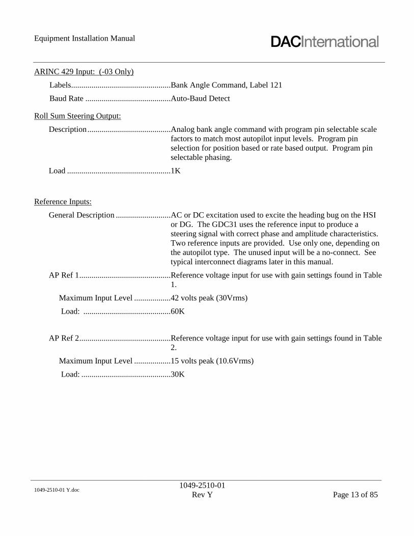
ARINC 429 Input: (-03 Only)
Labels.................................................Bank Angle Command, Label 121
Baud Rate ..........................................Auto-Baud Detect
Roll Sum Steering Output:
Description .........................................Analog bank angle command with program pin selectable scale
factors to match most autopilot input levels. Program pin
selection for position based or rate based output. Program pin
selectable phasing.
Load ...................................................1K
Reference Inputs:
General Description ...........................AC or DC excitation used to excite the heading bug on the HSI
or DG. The GDC31 uses the reference input to produce a
steering signal with correct phase and amplitude characteristics.
Two reference inputs are provided. Use only one, depending on
the autopilot type. The unused input will be a no-connect. See
typical interconnect diagrams later in this manual.
AP Ref 1 .............................................Reference voltage input for use with gain settings found in Table
1.
Maximum Input Level ..................42 volts peak (30Vrms)
Load: ...........................................60K
AP Ref 2 .............................................Reference voltage input for use with gain settings found in Table
2.
Maximum Input Level ..................15 volts peak (10.6Vrms)
Load: ............................................30K

Equipment Installation Manual
1049-2510-01 Y.doc
1049-2510-01
Rev Y
Page 14 of 85
AP Offset Input:
Autopilot Offset .................................For autopilots that use a signal common that is not airframe
ground. Many use 5Vdc (relative to airframe) as the heading bug
signal common. In these cases, connect the autopilot signal
common to the GDC31 offset input pin, P1-19.
Maximum Input Level ..................7 volts peak (5Vrms)
Load: ............................................10K
Annunciator Output:
GPS Coupled ......................................Normally Open relay contacts configured as a SPST switch
intended to control an external GPS mode annunciator. The
GDC31 closes the contacts when the steering output is valid. It
cycles the contacts between open and closed at a 1 Hz rate if
steering data is invalid. Closed contacts connect pins P1-24 and
P1-12.
Max current: .......................................250mA
Flag Input:
Description .........................................Valid input to the GDC31 at J1-25, supplied from a GPS receiver
Super Flag output (14 or 28V).
Voltage: ..............................................Greater than 6V is valid, less than 3V is invalid.
Load ...................................................200K ohms
Certification:
PMA
DO-178B ............................................Level C
DO-160D............................................D1/BADSXXXXXXABBBAVB/A3E3/XXX
Reliability:
MTBF .................................................Greater than 50,000 hours.

Equipment Installation Manual
1049-2510-01 Y.doc
1049-2510-01
Rev Y
Page 15 of 85
OPERATION:
Overview
The GDC31 Roll Steering Converter receives ARINC 429, Label 121 Bank Angle Command (BNR) (-03
model only), RS232 or RS422 serial data in RNAV 0, RNAV 1, King 0 or King 1 format from a GPS
navigation system. It extracts Cross Track, Ground Speed and Track Angle Error information from the
data stream to compute an appropriate bank angle command to return the aircraft to the Desired Track
computed by the GPS navigation system.
NOTE: The Bendix/King KLN-89B and KLN-94 GPS Receivers are not compatible with the GDC31 Roll
Steering Converter. See Appendix A, SIL GDC31-01.
Analog Output
The GDC31 produces an analog Roll Sum Steering (RSS) signal that drives the heading channel of the
autopilot. Phasing and amplitude of the RSS signal is based on the reference input supplied to the GDC31
from the autopilot and the gain and phase settings established by the program pins (refer to Tables 1, 2 and
3). The GDC31 will accept either an AC or a DC reference input as well as reference inputs that contain
an offset from airframe ground. The internal circuitry implements a multiplying Digital-to-Analog
converter that uses the external reference input to produce the desired signal output amplitude and phase
relative to the reference input. Certain installations (Century II and III, for example) will not accept a
heading error signal referenced to ground, so require the Isolation Coupler in order to transformer isolate
the GDC31 output signal.
Reference Inputs (Excitation)
The GDC31 contains two reference inputs to accommodate the wide range of reference voltages available.
Input Ref 1 will accommodate excitation voltages up to a maximum input of 42 volts peak (30Vrms).
Input Ref 2 will accommodate excitation voltages up to a maximum of 15 volts peak (15Vdc or 10.6Vrms).
The determination of which reference to use will depend on the gain needed to match the autopilot scale
factor as well as the maximum expected reference voltage. Certain installations (Century II and III, for
example) produce a reference voltage that is floating relative to airframe ground. These installations
require the Isolation Coupler in order to transformer isolate the GDC31 reference input signal.
ARINC 429 Input
The GDC31, (-03 model with software –001B or later) receives an ARINC 429 digital input containing
label 121.
429 Label
(Octal) Description
121 Bank Angle Command (BNR)

Equipment Installation Manual
1049-2510-01 Y.doc
1049-2510-01
Rev Y
Page 16 of 85
GPS Mode Annunciator Control
The GDC31 contains a Normally Open relay contact configured as a SPST switch to control the external
GPS mode annunciator. This annunciator is further controlled by external switching and is active when the
pilot selects GPS mode in place of heading mode with the external switch. Refer to the typical
interconnect diagram later in this manual. If GDC31 output data is valid, the relay contacts are closed,
allowing the mode annunciator to illuminate. If the data is invalid, the GDC31 will cause the mode
annunciator to blink at a 1 Hz rate and command the steering output to zero degrees of bank (wings level).
The GPS mode annunciator blinks if either the super flag input is invalid or the serial data from the GPS is
missing or not the correct format (see Appendix A).
Super Flag Input
The GDC31 reads the Super Flag (14 or 28Vdc) from the GPS receiver. If the flag is greater than 6Vdc,
the flag shall be considered valid, if less than 3Vdc, the flag shall be considered as invalid. If the Super
Flag indicates invalid, the GDC31 shall produce a steering signal of zero degrees, blink the GPS
annunciator relay and invalidate the ARINC 429 label 121, bank command data, and label 312, ground
speed data.

Equipment Installation Manual
1049-2510-01 Y.doc
1049-2510-01
Rev Y
Page 17 of 85
INSTALLATION
This Installation Manual is FAA Approved and contains detailed installation instructions for installing the
GDC31 into specific aircraft as listed in the AML-STC. There are required FARs that must be complied
with and followed to insure an airworthy installation. The Pre Modification Planning section will guide
you through these requirements.
This section provides details for the installation of the GDC31 Roll Steering Converter, including
configuration, wiring, mounting and checkout procedures. Follow the procedures and recommendations
found in this section to assure a successful installation.
Read this entire section before beginning the installation.
Prior to installation, determine the required scale factor and phasing for use with the aircraft’s autopilot.
Consider the location of the mode selector / annunciator switch; it should be installed within the pilot’s
primary field of view and easily accessible by the pilot.
Complete an electrical load analysis in accordance with AC 43.13-1B, Chapter 11 prior to starting the
aircraft modification to insure the aircraft has sufficient load capability.
Complete an aircraft weight and balance prior to aircraft modification to insure the aircraft has sufficient
weight and CG margin.
Material Not Supplied
The following items are required for the installation but not supplied:
Wire: MIL-W-22759/16 or equivalent
Shielded Wire: MIL-C-27500 or equivalent
Mounting screws: MS35206 6-32, 4 each
Circuit Breaker: Klixon 7277-2-2 or equivalent
Tie straps or lacing cord
Ring terminals (for grounding)
Splices
Special Tools
Use the following crimp tool to ensure reliable crimp contact connections to connector J1 and Annunciator.
Crimp tool M22520/2-01
Positioner M22520/2-08 (J1 crimp contacts)

Equipment Installation Manual
1049-2510-01 Y.doc
1049-2510-01
Rev Y
Page 18 of 85
Mounting Considerations
The GDC31 Roll Steering Converter can mount in the avionics bay, shelf or other suitable structure. It can
be mounted in any orientation.
The optional Isolation Coupler can mount in the avionics bay, shelf or other suitable structure. It can be
mounted in any orientation.
Attach the GDC31 and Isolation Coupler to suitable structure using the following hardware.
Screw, 8-32 X 1/2” MS35206-245
Flat Washer, #8 AN960-8L
Lock Washer, #8 MS35338-42
Nut, 8-32 MS35649-282
AN or MS self-locking nut plates may be used in place of the nut and lock washer specified above.
Mount the GPS/HDG mode annunciator / switch as near as practical to the autopilot mode controller. If
there is insufficient space there, mount the mode annunciator within the pilot’s primary field of view, near
the HSI or CDI.
Wiring Considerations
Wiring should be done in accordance with AC 43.13-1B, Chapter 11. Refer to the typical interconnect
diagram later in this manual for specifics. Use 22 to 24 AWG wire for all connections.
Fabricate wiring harness; refer to the interconnect diagrams and pin description. Test all the wiring for
continuity and for shorts. Insure aircraft power is on the correct pins of J1; refer to Table 6. Install slide
latch assembly onto J1 using instructions found later in this manual.
The mode annunciator/switch, P10280, comes pre-configured for 28V operation. For 14V operation,
perform the following steps:
1. Pull firmly on the edges of the lens to disengage the lamp assembly from the body. The lamp
assembly will hinge out and away from the body.
2. Remove and discard the four existing lamps, and replace with the four 14V lamps, P10301,
contained in the kit.
3. Push the lens firmly back into the body.

Equipment Installation Manual
1049-2510-01 Y.doc
1049-2510-01
Rev Y
Page 19 of 85
Pre Modification Planning
Annunciator/Switch
The GPS/ HDG annunciator switch should be located near the HSI/ DG or alternately, near the existing
autopilot mode annunciators.
Power Requirements
A suitable location will need to be determined for the RSS circuit breaker. It is recommended that power
to the GDC31 be supplied from the same source and the autopilot, typically the avionics buss.
Equipment Interfaces
GPS
The GDC31 provides steering command through the HDG Datum of the autopilot based on GPS input.
The GPS must be capable of providing either ARINC 429 label 121 or RS232 data in “Aviation Format”
described in section appendix A and appendix B-ARINC 429 input of the manual.
Autopilot
The GDC31 is compatible with the autopilot models listed in the Limitations Section of the GDC 31 STC.
During installation, the GDC31 in configured to emulate the Heading Datum output of the existing HSI or
DG. Refer to the wiring diagrams in Section appendix E of this manual.
No modifications to the autopilot wiring are necessary. The GDC31 will use the same Heading Datum
reference feeding the HSI or DG. As part of this modification, the HSI or DG Heading Datum error signal
is re-wired through the supplied GPS / HDG annunciator switch, enabling either the current Heading
Datum error signal of the GDC31 steering signal to feed the autopilot heading datum input
Installation Summary
Mechanical Summary
__Panel layout is evaluated for the best placement of the GPS/HDG annunciator.
__Based on an evaluation of the DO-160 limitations found in this manual, a suitable location is
found for the GDC31 computer.
__Weight and balance is performed.
Electrical Summary
__Electrical Load Analysis is performed.
__A dedicated circuit breaker in location is determined.
__Power and ground lines are installed.
__An applicable wiring diagram is selected from those available in this manual.
__Reference and heading datum interconnects are installed per the selected diagram.
Ground Checkout Summary
__Wiring is verified.
__Basic operation is verified with the ground test.

Equipment Installation Manual
1049-2510-01 Y.doc
1049-2510-01
Rev Y
Page 20 of 85
Functional Flight Test Summary
__Autopilot HDG Datum performance is evaluated.
__GDC31 RSS performance is evaluated.
NOTE:
The following setup procedures are for diagnosing interfacing problems.
Steering Output Scale Factor Determination
The GDC31 is designed to mimic the heading error signal produced by the existing HSI or DG, so it can
operate with the wide variety of autopilots in current use. These various autopilots employ a wide range of
reference voltages and scale factors to interface with the array of HSI and DG control heads. Reference
voltage, or excitation, is the autopilot signal used to excite the Heading Select bug in the HSI or CDI. As
used in this manual, scale factor refers to the autopilot’s response to the heading error input signal,
expressed in volts per degree of bank. Examples are 200mv/deg and 60mv/deg. Examples of excitation
voltage are 26Vac and 15Vdc. The GDC31 first computes the bank angle using data from the GPS. It then
uses the reference voltage along with the scale factor setting (gain setting) to produce a signal that feeds
into the autopilot’s heading error input to produce the desired bank angle.
The GDC31 has ten (10) choices for scale factor, selected with a combination of program pins (3 each) and
reference inputs (2 each). Tables 1 and 2 describe the program pin combinations for the various scale
factors. To determine the appropriate setting for a given autopilot, first determine the autopilot excitation
amplitude in volts (AC or DC). Next, determine the autopilot scale factor from the autopilot maintenance
data. The scale factor needs to be expressed as volts/degree of bank. Divide the scale factor by the
excitation (scale factor / excitation voltage). Then look in Tables 1 and 2 for the nearest Scaling value to
the one just computed.
If the gain is set too high, the commanded course intercept will be overly aggressive. For 90-degree course
changes, too much gain will often cause the aircraft to turn inside the new course then S-turn back to
capture the track.
If the gain is set too low, the commanded course intercept will be sluggish. For a 90-degree course change,
too little gain will often cause the aircraft to overshoot the desired course then S-turn back to capture the
track. Some autopilots limit the maximum bank angle to less than the 30 degrees, 22 degrees for example.
In these cases, the aircraft will exhibit the symptoms of too little gain because the aircraft cannot turn sharp
enough to capture the track without overshooting. Examine the attitude indicator during a 90-degree
course change to verify that the aircraft banks to 30 degrees, or in the case of rate based autopilots, to a
standard rate turn.

Equipment Installation Manual
1049-2510-01 Y.doc
1049-2510-01
Rev Y
Page 21 of 85
Configuration Pins
The GDC31 produces one of five (5) different RSS output levels for each reference input. This scaling
selection is accomplished with program pins J1-10, J1-21 (-03 model only) and J1-22. Tables 1 and 2
define the scale factors available for each of the reference inputs, Ref 1 and Ref 2.
Gain Settings Using Ref 1 input J1-18
(Excitation: Maximum input of 42 volts peak, (30 Vrms)
Scaling J1-10 J1-21 (1) J1-22
0.030276 Open Ground Open (1)
0.015138 Open Open Open
0.011590 Open Open Ground
0.007687 Ground Open Open
0.003844 Ground Open Ground
Table 1
RSS Output Scaling Selection for Ref 1 input
(1) Applicable to software -001B or later.
Gain Settings Using Ref 2 input J1-6
(Excitation: Maximum input of 15 volts peak, (15 Vdc or 10.6 Vrms)
Scaling J1-10 J1-21 (1) J1-22
0.066888 Open Ground Open (1)
0.033444 Open Open Open
0.025606 Open Open Ground
0.016983 Ground Open Open
0.008492 Ground Open Ground
Table 2
RSS Output Scaling Selection for Ref 2 input
(1) Applicable to software -001B or later.

Equipment Installation Manual
1049-2510-01 Y.doc
1049-2510-01
Rev Y
Page 22 of 85
Phase Selection
The GDC31 will accommodate steering signals that are in phase with the reference or out of phase with the
reference. For DC heading error signals, in-phase means a positive error signal produces a right turn, a
negative error signal produces a left turn. Determine the correct phasing from the autopilot maintenance
data then wire P1-13 accordingly.
If the phasing is incorrectly wired, the autopilot will turn the opposite direction when coupled to the
GDC31 Roll Steering Converter.
Phase P1-13
IN Phase with Reference Open
OUT of Phase with Reference Ground
Table 3
Phase Selection

Equipment Installation Manual
1049-2510-01 Y.doc
1049-2510-01
Rev Y
Page 23 of 85
Position/Rate Selection
The GDC31 is designed to operate with both position based and rate based autopilots. Configuration is set
by program pin P1-23.
Scaling J1-23
Position Based Open
Rate Based Ground
Table 4
Position / Rate Selection
Position based autopilots require attitude information from the attitude indicator or vertical gyro. Rate
based autopilots require turn rate information from the turn coordinator rate gyro. Determine the autopilot
type, if it is rate based then connect J1-23 to program pin common, J1-11.
Baud Rate Selection
Table 5 removed in revision U.
The GDC31 Roll Steering Converter, P/N 1049-4000-03, with software -001B or later, will accept two (2)
baud rates for GPS data configured using program pin P1-9.
Baud Rate P1-9
9600 Open
4800 Ground
Table 6
Serial Baud Rate Selection
Note: Use Program Pin Common, J1-11, as ground for all program pin connections.
GPS Receiver Setup
Refer to the manufacturer's instructions for the GPS interfaced to the GDC31 RSC. Configure the GPS to
output the RS232 Aviation Format data described in Appendix A.

Equipment Installation Manual
1049-2510-01 Y.doc
1049-2510-01
Rev Y
Page 24 of 85
REMOVAL AND REPLACEMENT
Removal, GDC31
1. Open the circuit breaker powering the GDC31.
2. Remove the connector by disengaging the slide latch then pulling the connector free.
3. Remove four (4) screws securing the unit to the airframe.
Replacement, GDC31
1. Open the circuit breaker powering the GDC31.
2. Attach the unit to the airframe with four (4) screws.
3. Seat the connector then engage the slide latch to secure.
4. Close circuit breaker.
5. Perform ground functional test found under Equipment Checkout in this manual.
Removal, Mode Annunciator
1. Open the circuit breaker powering the GDC31.
2. Pull firmly on the edges of the lens to disengage the lamp assembly from the body. The lamp
assembly will hinge out and away from the body.
3. Release the two (2) pawls by unscrewing the flat-head screws located inside the body.
4. Unplug the lamp module from the sleeve.
Replacement, Mode Annunciator
1. Open the circuit breaker powering the GDC31.
2. Plug the lamp module into the sleeve.
3. Secure by engaging the two (2) pawls to the sleeve.
4. Plug the lamp module into the body - it will snap into place.
5. Close the circuit breaker.
6. Perform ground functional test found under Equipment Checkout in this manual.

Equipment Installation Manual
1049-2510-01 Y.doc
1049-2510-01
Rev Y
Page 25 of 85
EQUIPMENT CHECKOUT
The GDC31 provides conversion of RS232 serial data or ARINC 429 digital data (1049-4000-03 with
software –001B or later) from a GPS receiver into a steering signal connected to the autopilot heading
channel through switching controlled by the HDG/GPS mode selector switch. There are no other operator
controls associated with the GDC31 unit.
The GPS receiver and the Autopilot must both be operational in order to perform this functional checkout.
Ground Functional Test
1. Insure that all control surfaces are clear and that the control wheel is centered in roll.
2. Apply power to the GPS Receiver and Autopilot.
3. Set the HDG/GPS Mode selector to HDG.
4. On the HSI, center the heading bug.
5. Engage the autopilot in Heading Mode.
6. Operate the heading bug; observe that the control wheel turns left and right in response to the
heading bug operation.
7. Center the control wheel using the heading bug.
8. Create and activate a flight plan in the GPS unit according to existing maintenance and / or flight
manual instructions.
9. Place the HDG/GPS Mode selector in the GPS position. With RS232 interface, observe GPS
illuminates and is not blinking. With ARINC429 interface, Label 121 may not validate with less
than 30 knots ground speed. If GPS receiver has test page mode, set receiver to test page to test for
steady GPS indication. Refer to applicable GPS receiver documentation for state of Label 121
valids. If receiver does not provide valid ground speed for testing then it will be necessary to taxi
aircraft in excess of 30 knots ground speed or fly to test for valid.
10. Remove power from the GPS receiver.
11. Observe that the GPS mode annunciator begins to blink within 15 seconds.
12. Verify that the control wheel centers once the GPS mode annunciator blinks.
13. Disengage the autopilot.
14. Ground test complete. Secure aircraft power.
Flight Functional Test
1. Set the HDG/GPS Mode selector to HDG.
2. On the HSI, center the heading bug.

Equipment Installation Manual
1049-2510-01 Y.doc
1049-2510-01
Rev Y
Page 26 of 85
3. Engage the autopilot in Heading Mode.
4. Operate the heading bug; observe that the control wheel turns left and right in response to the
heading bug operation.
5. Center the heading bug.
6. Create and activate a flight plan in the GPS unit according to existing maintenance and / or flight
manual instructions. Manually fly the aircraft until the cross track error is between 1 and 3 miles.
7. Place the HDG/GPS Mode selector in the GPS position. Observe that GPS illuminates and is not
blinking.
8. Observe that the aircraft turns to intercept the course selected in Step 6. Note: The GDC31 limits
the intercept angle to 45º maximum. (Intercept angle = difference between Desired Track and
Track.)
9. Observe that the aircraft captures the course without overshoot or undershoot.
10. Operate the heading bug; observe that the heading bug has no effect.
11. Select HDG on the HDG/GPS Mode selector.
12. Observe that the aircraft follows the heading bug.
13. Flight test complete.

Equipment Installation Manual
1049-2510-01 Y.doc
1049-2510-01
Rev Y
Page 27 of 85
CONTINUED AIRWORTHINESS:
This section provides data intended to assist the installer with establishing Instructions for Continued
Airworthiness as required by FARs 23.1529, 25.1529, 27.1529 and 29.1529.
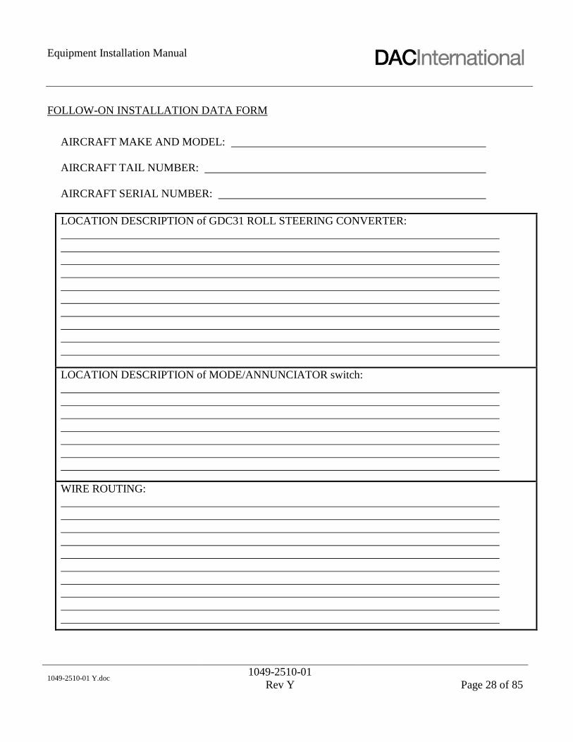
INSTRUCTIONS TO COMPLETE FOLLOW-ON INSTALLATION DATA FORM:
For follow-on installations, complete the data sheet found on the following page. Also include a wiring
diagram specific to the installation.
On the data sheet, complete the aircraft make and model, registration number and serial number
sections. Then describe the location of the GDC31 converter in sufficient detail, using station location
numbers or other common reference points. For example, “GDC31 located under the instrument panel,
right outboard side.” Use of sketches is recommended. Likewise, describe the location of the
annunciator / switch. Describe or sketch the wire bundle routing.
Produce a wiring diagram specific to the aircraft installation. Use of wiring diagrams extracted from the
installation manual, 1049-2510-01, or sketches are also acceptable. Also a copy can be obtained from
the ICA.
Include a copy of the Instructions for Continued Airworthiness (ICA) (1049-2170-02) along with the
data sheet and wiring diagram with the aircraft records.
A copy of the Instructions for Continued Airworthiness (1049-2170-02) may be obtained from the DAC
International web site at http://www.dacint.com/products or by contacting DAC International at 1-800-
527-2531.
Equipment Installation Manual
1049-2510-01 Y.doc
1049-2510-01
Rev Y
Page 28 of 85
FOLLOW-ON INSTALLATION DATA FORM
AIRCRAFT MAKE AND MODEL:
AIRCRAFT TAIL NUMBER:
AIRCRAFT SERIAL NUMBER:
LOCATION DESCRIPTION of GDC31 ROLL STEERING CONVERTER:
LOCATION DESCRIPTION of MODE/ANNUNCIATOR switch:
WIRE ROUTING:

Equipment Installation Manual
1049-2510-01 Y.doc
1049-2510-01
Rev Y
Page 29 of 85
The GDC31 meets the environmental test categories detailed below in accordance with
RTCA/DO-160D, Environmental Conditions and Test Procedures for Airborne Equipment.
NOMENCLATURE: Model GDC31 Roll Steering Converter
PART NO: 1049-4000-XX-XXXX
MANUFACTURER: DAC International
ADDRESS: 6702 McNeil Drive, Austin, TX 78729
Section Category Remarks
4.0 Temperature and Altitude D1 50,000 Ft Temperature controlled
5.0 Temperature Variation B Partially controlled temperature
6.0 Humidity A Standard Humidity
7.0 Operational Shock and Crash Safety D Fixed wing
8.0 Vibration S
Curves L, M and C.
Fixed Wing – Turbojet, Turbofan, Turboprop
and reciprocating
Instrument Panel or Fuselage
9.0 Explosion Proofness X Not Tested
10.0 Waterproofness X Not Tested
11.0 Fluids Susceptibility X Not Tested
12.0 Sand and Dust X Not Tested
13.0 Fungus Resistance X Not Tested
14.0 Salt Spray X Not Tested
15.0 Magnetic Effect A 0.3 meter to 1.0 meter
16.0 Power Input B Alternator / Rectifiers
17.0 Voltage Spike B 56 volts
18.0 AF Conducted Susceptibility – Power
Inputs
B Alternator / Rectifiers
19.0 Induced Signal Susceptibility A
20.0 Radio Frequency Susceptibility
(Radiated and Conducted) V 50 volts/meter
21.0 Emission of Radio Frequency Energy B
22.0 Lightning Induced Transient
Susceptibility A3E3
23.0 Lightning Direct Effects X Not Tested
24.0 Icing X Not Tested
25.0 ESD X Not Tested

Equipment Installation Manual
1049-2510-01 Y.doc
1049-2510-01
Rev Y
Page 30 of 85
Table 7 removed in revision U.
CONNECTOR PIN OUT: (1049-4000-03)
The GDC31 Roll Steering Converter, P/N 1049-4000-03, with software -001B or later, contains a single
25-pin male connector, J1, per MIL-C-24308. The mating connector, P1, is described previously under the
section “Equipment Supplied”.
Pin Signal Function
1 A+ 28 Vdc Primary Power
2 Serial Out RS232 Output
3 Serial In RS232 Input
4 Reserved (VPP)
5 AP-OUT Autopilot Output
6 AP-REF2 Autopilot Reference, 10.6Vac max (1)
7 RX-A ARINC 429 Receive A
8 RX-B ARINC 429 Receive B
9 BAUDSEL1 Serial Baud Rate Select 1
10 GAINSEL1 Autopilot Gain Select 1
11 Prog Pin Common Program Pin Common
12 GPS Lamp A GPS Mode Annun Relay Armature
13 Phase Select Phase select program pin
14 Power Common 28 Vdc Return
15 AP-COM Autopilot Common (ground)
16 Serial Common RS232 Common
17 Reserved (/PGM Enable)
18 AP-REF1 Autopilot Reference, 30Vac max (1)
19 AP-OFFSET Autopilot Offset Input (A/P Common) +6Vdc max
20 429 Shield ARINC 429 Shield Common
21 GAINSEL2 Autopilot Gain Select 2 (2)
22 GAINSEL0 Autopilot Gain Select 0
23 TYPESEL0 Rate Based Select
24 GPS Lamp B GPS Mode Annun Relay N.O. Contact
25 Super Flag In 14 / 28 Vdc valid flag from GPS
Table 8
J1 Pin Description
NOTES: Do not use pins labeled Reserved. These are for factory test and In-Circuit-Programming
(1) Connect only one reference. Refer to “Reference Inputs” section.
(2) Applicable to SW -001B only.

Equipment Installation Manual
1049-2510-01 Y.doc
1049-2510-01
Rev Y
Page 31 of 85
OUTLINE DRAWINGS
GDC31 Outline
Note: Dimensions are in inches.

Equipment Installation Manual
1049-2510-01 Y.doc
1049-2510-01
Rev Y
Page 32 of 85
Switch / Annunciator Outline
Outline for part number P10280
Note: Dimensions are in inches.
PANEL CUTOUT
1 26
811
3 45 7
9 1012
PIN OUT
(REAR VIEW)

Equipment Installation Manual
1049-2510-01 Y.doc
1049-2510-01
Rev Y
Page 33 of 85
Isolation Coupler Outline

Equipment Installation Manual
1049-2510-01 Y.doc
1049-2510-01
Rev Y
Page 34 of 85
SLIDE LATCH ASSEMBLY
Assemble the slide latch mechanism, part number P10219 or P10053, onto the mating connector as
pictured using the hardware supplied with the slide latch.
SLIDE LATCH
SCREW
CONNECTOR
FLAT WASHER
NUT
LOCK WASHER

Equipment Installation Manual
1049-2510-01 Y.doc
1049-2510-01
Rev Y
Page 35 of 85
APPENDIX A – RS232 AVIATION FORMAT
The GDC31 accepts data in the RS232 Aviation Format produced by most GPS panel mount receivers.
Various manufacturers refer to this data as RNAV, KING or MAPCOM. The following table contains the
minimum data set required by the GDC31. The GDC31 is designed to disregard additional data records
transmitted from the GPS.
NOTE: The Bendix/King KLN-89A and KLN-94 GPS Receiver update rate of track is too slow to
maintain aircraft on course. If connected to a KLN-89A or KLN-94, expect a 3-degree track angle error
left and right of course over a 1 – 2 minute period.
GPS Receivers that supply the following minimum data set and any of the previously mentioned baud rates
should be compatible with the GDC31. Insure the GDC31 is configured for the correct baud rate (refer to
"Serial Baud Rate Selection" located earlier in this manual).
Aviation Data Format Description
<STX> ASCII Start of Transmission character
… other data
C284<cr> track; in degrees magnetic (ex: 284º)
D162<cr> ground speed; in knots (ex: 162 kt)
GR0050<cr> crosstrack; L (left) or R (right) in hundredths of
nautical miles (ex: Right 0.5nm)
I2855<cr> desired track; in tenths of degrees (ex: 285.5º)
… other data
<ETX> ASCII End of Transmission character
1. Each data field ends in a <cr> or <cr> <lf>
2. <cr> - ASCII carriage return character (0D hex)
3. <lf> - ASCII line feed character (0A hex)

Equipment Installation Manual
1049-2510-01 Y.doc
1049-2510-01
Rev Y
Page 36 of 85
The GDC31 Roll Steering Converter, P/N 1049-4000-03, with software -001B or later, will accept 4800 or
9600 baud. Software –001B accepts the following data in RS232 Aviation Format produced by the
CNX80 and GNS480 GPS panel mount receivers. GPS Receivers that supply the following minimum data
set (excluding Horizontal Command Signal) and any of the previously mentioned baud rates should be
compatible with the GDC31. Insure the GDC31 is configured for the correct baud rate (refer to "Serial
Baud Rate Selection" located earlier in this manual).
Aviation Data Format Description
<STX> ASCII Start of Transmission character
… other data
C284<cr> track; in degrees magnetic (ex: 284º)
D162<cr> ground speed; in knots (ex: 162 kt)
GR0050<cr> crosstrack; L (left) or R (right) in hundredths of
nautical miles (ex: Right 0.5nm)
I2855<cr> desired track; in tenths of degrees (ex: 285.5º)
hR150<cr> Horizontal Command Signal; L (left) or R (right)
in tenths of degrees (ex: Right 15.0 degrees)
… other data
<ETX> ASCII End of Transmission character
1. Each data field ends in a <cr> or <cr> <lf>
2. <cr> - ASCII carriage return character (0D hex)
3. <lf> - ASCII line feed character (0A hex)

Equipment Installation Manual
1049-2510-01 Y.doc
1049-2510-01
Rev Y
Page 37 of 85
APPENDIX B – ARINC 429 INPUT
The GDC31 Roll Steering Converter, P/N 1049-4000-03, with software –001B accepts input of ARINC
429 Label 121 – Bank Angle Command in the following format:
Label 121 - Bank Angle Command
Label 121 shall be formatted as follows:
3
2
3
1
3
0
2
9
2
8
2
7
2
6
2
5
2
4
2
3
2
2
2
1
2
0
1
9
1
8
1
7
1
6
1
5
1
4
1
3
1
2
1
1
1
0
0
9
0
8
0
7
0
6
0
5
0
4
0
3
0
2
0
1
P SSM S Roll Angle (two’s compliment if negative) PAD SDI Label 121
P = odd parity
SSM = sign status matrix
00 = fail/warning
11 = normal
S = sign bit, 0=positive roll angle
SDI = source/destination identifier (always zero)
Data Range: ±180°
Resolution: 0.01°

Equipment Installation Manual
1049-2510-01 Y.doc
1049-2510-01
Rev Y
Page 38 of 85
APPENDIX C – GPS RECEIVER INTERCONNECT
Connect the GDC31 to a single GPS source only. The following diagrams are the recommended
interconnections for each source. Refer to Figure 1 for RS232 interconnect. Refer to Figure 2 for ARINC
429 interconnect.
NOTE: For Procedure Turns and Holding Patterns capabilities provided by some GPS Receivers interface
to the ARINC 429 output of the receiver shown in Figure 2.
SUPER FLAG Super Flag25
RS232 OUT
RS232 COM
GPS RECEIVER
Serial In
Serial Com
GDC31
3
16
Figure 1 RS232 Interconnect Diagram
14/28VBUS
429 TX-B
429 SHIELD
429 TX-A
GPS RECEIVER
Super Flag25
429 RX-A
429 RX-B
429 SHIELD
8
20
7
GDC31
Figure 2 ARINC 429 Interconnect Diagram

Equipment Installation Manual
1049-2510-01 Y.doc
1049-2510-01
Rev Y
Page 39 of 85
APPENDIX D - OPTIONAL LIGHTING CONTROLS
BUSLIGHTING
A+
A+P10280
6
SWITCH/ANN
Figure 1 Day / Night Switch Interconnect Diagram
1N4001
DIMMER
+28VAVIONICSPWR
RELAYM39016/6-107P P10280
SWITCH/ANN
6
Figure 2 Relay Interconnect Diagram
Equipment Installation Manual
1049-2510-01 Y.doc
1049-2510-01
Rev Y
Page 40 of 85
APPENDIX E - TYPICAL INTERCONNECT
All wiring, wire gauge and wire type shall be according to the INSTALLATION section of this manual.
Mounting shall use the hardware called out in this manual or AN / MS equivalent fasteners.
NOTE:
THESE SCHEMATICS ARE FOR REFERENCE ONLY. For configurations not illustrated by drawing
refer to the Installation section earlier in this manual for configuration, wiring, mounting and checkout
procedures. Many autopilot units provide both an AC and a DC excitation signal. Verify the HSI or DG is
connected to the autopilot signal and reference as shown in that diagram. Refer to the HSI or DG
manufacturer’s data and the autopilot manufacturer’s data for additional information.
Visit our website: www.dacint.com/GDC31 for additional information.

Equipment Installation Manual
GDC31 Roll Steering Converter
1049-2510-01 Y.doc
1049-2510-01
Rev Y
Page 41 of 85
AUTOPILOT INTERFACE
-03 ONLY21GAIN SELECT 2PROGRAM PINS
PROGRAM PIN COMMON
RSS OUTPUT 5
RSS COMMON
AP OFFSET7
6
5
REF2
19
6
REF1
15
18
TYPE SELECT
PHASE SELECT4
3
11
13
23RS232 or ARINC 429
Select
8ARINC 429 TX-B-01
ONLY
BAUD SELECT 0
BAUD SELECT 1
GAIN SELECT 0
GPS LAMP A
GAIN SELECT 12
1
22
10
21
9
12
429 COMMON
GPS LAMP B 24
20
ONLY
RS232 or ARINC 429
GPS INTERFACE
ONLY
SELECT
-03
ARINC 429 TX-A
RS232 RX IN
SERIAL COMMON
SUPER FLAG IN 25
7
16
3
POWER COMMON
ARINC 429 RX-A
ARINC 429 RX-B
429 COMMON
8
20
7
A+
14
1
GPS INTERFACE
-01 ONLY
<=RS232
GDC31J1 2A
SEE TABLES 5 & 6
SEE TABLES 1 AND 2
SEE TABLE 4
SEE TABLE 3
REF1 - USE FOR EXCITATION VOLTAGES GREATER THAN 15 VOLTS PEAK
FOR USE WITH AUTOPILOTS THAT USE A SIGNAL REFERENCE
SEE TABLES 1 AND 2
REF2 - USE FOR EXCITATION VOLTAGES LESS THAN 15 VOLTS PEAK
SEE TABLES 1 AND 2
THAT IS A VOLTAGE ABOVE AIRFRAME COMMON, TYPICALLY 5VDC
EXCITATION (15 Vpk to 42 Vpk)
EXCITATION (LESS THAN 15 Vpk)
ISOLATION COUPLER IS USED TO TRANSFORMER ISOLATE THE
GDC31 REFERENCE AND / OR OUTPUT FOR INSTALLATIONS WHERE
THESE SIGNALS ARE NOT REFERENCED TO AIRFRAME GROUND.
AUTOPILOT
SIGNAL REFERENCE
HDG ERROR IN
EXCITATION
GROUND
EXCITATION
HDG ERROR FROM HSI / CDI
SWITCH / ANNUNCIATOR
P10280 (28V OR 14V)
HDG
GPS12
4
7
1
5
2
11
3
10
8
6
SUPER FLAG OUT
RS232 TX OUT
SHIELD
14V OR 28 VDC BUS
GPS
ARINC 429 TX-B
ARINC 429 TX-A
SHIELD
LIGHTING VOLTAGE
8
7
6
3
5
4
2
1
1049-4801-01
2:1
COUPLERISOLATION
12
2
9
2:1
1
2:1
2:1
14
1311
6
10
45
3
Figure 1 - TYPICAL INTERCONNECT

Equipment Installation Manual
GDC31 Roll Steering Converter
1049-2510-01 Y.doc
1049-2510-01
Rev Y
Page 42 of 85
P10280SWITCH / ANNUNC
10
23
12
6
11
GPS
HDG
81
5
4
SWITCH / ANNUNC
SCHEMATICP10280
7
BEXC
LIGHTING BUS
HDG SIGNAL A
E
G502A
D
J1
EXC
1412AP-OFFSET19
IF AIRCRAFT TURNS AWAY FROM TRACK LINE, REMOVE PHASE JUMPER AND RETEST
CONNECT PARALLEL TO EXISTING WIRING
14 OR 28VDC
FOR GPS INPUT SEE APPENDIX C - GPS RECEIVER INTERCONNECT
ARINC 429 INPUT AVAILABLE ON PINS 7 & 8 ON PN 1049-4000-03 WITH SOFTWARE -001B OR LATER
ARINC 429 OUTPUT AVAILABLE ON PINS 7 & 8 ON PN1049-4000-01 WITH SOFTWARE -001A
ENSURE ROLL CENTERING KNOB IS CENTERED
DASHED LINES REPRESENT EXISTING WIRING
GROUND BOTH ENDS OF ALL SHIELDING
SERIAL COMMON
429 RX-B
429 RX-A
429 SHIELD20
8
7
SERIAL IN
SUPER FLAG IN
16
25
3
14
TYPE SELECT
BAUDSEL1
23
1
9
6
3
4
2
RSC
7277-2-2
2A
4.5 VAC Pk-Pk 400HZ
400HZ RTN (A/C GRND)18
PROG PIN COMMON
GPS LAMP A121
2
6
3
12
5
11
TYPE SELECT
GAINSEL0
PHASE SELECT
22
13
23
GAINSEL1
GPS LAMP B
11
10
24
8
4
10
7
AP-OUT
AP-COM
AP-REF2
15
6
5
5
6
2
4
1
3
SIG COM
AC HDG IN17
23
ISOLATION COUPLERRSS CONVERTERGDC31 1049-4801-01
DATUM
20
J1
AC HEADINGCA-395A (42660-1xxx)
ARC-300A
31
92
10
1311
5
6
4
ISOLATION COUPLER1049-4801-01SCHEMATIC
Figure 2 - ARC 300A with G502A

Equipment Installation Manual
GDC31 Roll Steering Converter
1049-2510-01 Y.doc
1049-2510-01
Rev Y
Page 43 of 85
P10280
10
7
4
8
11
1
12
3
5
6
2
SWITCH / ANNUNC
LIGHTING BUS
21HDG SIGNAL
19
20
IG-832 A/CNSD-1000NSD-360A
EXC
EXC
CONNECT PARALLEL TO EXISTING WIRING
14 OR 28VDC
FOR GPS INPUT SEE APPENDIX C - GPS RECEIVER INTERCONNECT
ARINC 429 INPUT AVAILABLE ON PINS 7 & 8 ON PN 1049-4000-03 WITH SOFTWARE -001B OR LATER
ARINC 429 OUTPUT AVAILABLE ON PINS 7 & 8 ON PN 1049-4000-01 WITH SOFTWARE -001A
ENSURE ROLL CENTERING KNOB IS CENTERED
DASHED LINES REPRESENT EXISTING WIRING
SUPER FLAG IN25
429 RX-A
429 RX-B
429 SHIELD
8
20
7
SERIAL IN
SERIAL COMMON16
3
14
1
6
4
3
2A
7277-2-2
2
PROG PIN COMMON
GAINSEL110
GAINSEL0
GAINSEL2
PHASE SELECT
21
13
22
TYPE SELECT
AP-OFFSET
23
19
11
BAUDSEL19
AP-REF2
GPS LAMP A
GPS LAMP B
12
24
6
AP-COM
AP-OUT5
15
RSC
CA-395A
J1/P4
DATUM
18
20
17
ARC-300A
DC HEADING
RSS CONVERTERGDC31
+10VDC REG
DC HDG IN
-10VDC REG
8
HDG
12
3
6
11
2
GPS
1
P10280SCHEMATIC
SWITCH / ANNUNC
10
5
4
7
Figure 3 - ARC 300A (DC) with NSD-360

Equipment Installation Manual
GDC31 Roll Steering Converter
1049-2510-01 Y.doc
1049-2510-01
Rev Y
Page 44 of 85
20 429 SHIELD1112 DASHED LINES REPRESENT EXISTING WIRING5
IF AIRCRAFT TURNS AWAY FROM TRACK LINE, REMOVE PHASE JUMPER AND RETEST
GROUND BOTH ENDS OF ALL SHIELDING
CONNECT PARALLEL TO EXISTING WIRING
FOR GPS INPUT SEE APPENDIX C - GPS RECEIVER INTERCONNECT
ARINC 429 INPUT AVAILABLE ON PINS 7 & 8 ON PN 1049-4000-03 WITH SOFTWARE -001B OR LATER
ARINC 429 OUTPUT AVAILABLE ON PINS 7 & 8 ON PN 1049-4000-01 WITH SOFTWARE -001A
3188
SCHEMATIC
SWITCH / ANNUN
LIGHTING BUS
10
63
8
4
HDG
GPS
2
15
7
P10280
429 RX-B
429 RX-A
8
7
Serial Com
Super Flag2525
16
3
2
Serial In3
14
5
2
6
3
11
12
1
13
Gain Sel 022
Phase Sel
1
13
Prog Com11
14
11
Lamp B24
AP Com15
Lamp A12
5
6
4
HDG ERR LO Y-
HDG ERR HI X-
AC REF LO C-
AC REF HI H-
B
E
A
D
COLLINSPN 101
1049-4801-01
10
4
7
AP Out
Ref 1
5
9
10
12
2
1
RSS CONVERTERGDC31
SWITCH / ANNUNP10280 COUPLER
ISOLATION
2A
7277-2-2 12
14 OR 28VDC
RSC
2
9
1
14
6
1113
10
45
3
1049-4801-01
SCHEMATIC
COUPLERISOLATION
HEADING ERROR
10 VAC 400 HZ RETURN
10 VAC 400HZ
E
J3/P18
F
J1/P16
E
HDG COMC
ARC 400S530A
Figure 4 - ARC 400/S530A with PN 101

Equipment Installation Manual
GDC31 Roll Steering Converter
1049-2510-01 Y.doc
1049-2510-01
Rev Y
Page 45 of 85
P10280SWITCH / ANNUNC
BEXC
LIGHTING BUS
HDG SIGNAL A
D
G502A
EXC
BAUDSEL19
IF AIRCRAFT TURNS AWAY FROM TRACK LINE, REMOVE PHASE JUMPER AND RETEST
CONNECT PARALLEL TO EXISTING WIRING
FOR GPS INPUT SEE APPENDIX C - GPS RECEIVER INTERCONNECT
14 OR 28VDC
ARINC 429 INPUT AVAILABLE ON PINS 7 & 8 ON PN 1049-4000-03 WITH SOFTWARE -001B OR LATER
ARINC 429 OUTPUT AVAILABLE ON PINS 7 & 8 ON PN1049-4000-01 WITH SOFTWARE -001A
ENSURE ROLL CENTERING KNOB IS CENTERED
DASHED LINES REPRESENT EXISTING WIRING
SERIAL COMMON
3 SERIAL IN
429 SHIELD
429 RX-B
20
8
429 RX-A
SUPER FLAG IN25
7
16
TYPE SELECT
1
14
23
6
3
4
2
RSC
2A
7277-2-2
19 400HZ RTN16
PROG PIN COMMON
11 24 GPS LAMP B
6
2
5
3
12
AP-OFFSET
GAINSEL0
PHASE SELECT13
19
22
GAINSEL1
GAINSEL2
10
21
11
8
1
7
4
10
GPS LAMP A
AP-REF2
AP-COM
6
12
15
AP-OUT5
CHASSIS GND35
20 AC HDG IN
CA-550A/FD
J1/P4
DATUM
SPERRY/ARC-400B
10VAC HEADING
GDC31RSS CONVERTER
10VAC 400HZ33
J2/P5
HDG
6
12
3
8
GPS
11
2
1
5
P10280SWITCH / ANNUNC
SCHEMATIC
104
7
Figure 5 - ARC 400B/CA-550A/FD (10VAC) with G502A

Equipment Installation Manual
GDC31 Roll Steering Converter
1049-2510-01 Y.doc
1049-2510-01
Rev Y
Page 46 of 85
10
7
4
1
12
11
8
5
2
3
6
SWITCH / ANNUNCP10280
LIGHTING BUS
21HDG SIGNAL
19
20
IG-832 A/CNSD-1000NSD-360A
EXC
EXC
DASHED LINES REPRESENT EXISTING WIRING
ENSURE ROLL CENTERING KNOB IS CENTERED
ARINC 429 OUTPUT AVAILABLE ON PINS 7 & 8 ON PN 1049-4000-01 WITH SOFTWARE -001A
ARINC 429 INPUT AVAILABLE ON PINS 7 & 8 ON PN 1049-4000-03 WITH SOFTWARE -001B OR LATER
FOR GPS INPUT SEE APPENDIX C - GPS RECEIVER INTERCONNECT
14 OR 28VDC
CONNECT PARALLEL TO EXISTING WIRING20 429 SHIELD
429 RX-B
429 RX-A
SUPER FLAG IN
7
8
25
SERIAL IN
SERIAL COMMON
3
16
14
1
6
3
4
2
2A
7277-2-2
21
35
PROG PIN COMMON
23 TYPE SELECT
BAUDSEL1
AP-OFFSET
PHASE SELECT
9
13
19
GAINSEL0
GAINSEL2
GAINSEL1
22
21
10
6 AP-REF2
GPS LAMP B
GPS LAMP A
24
11
12
AP-OUT
AP-COM
5
15
RSC
SIGNAL GND
CHASSIS GND
J1/P4
DATUM
10
24
27
SPERRY/ARC-400BCA-550A/FD
DC HEADING
GDC31RSS CONVERTER
-10VDC REG
+10VDC REG
DC HDG IN
8
12
3
6
11
1
2
GPS
HDG
SWITCH / ANNUNCP10280
SCHEMATIC
107
4
5
Figure 6 - ARC 400B/CA-550A/FD (DC) with NSD-360
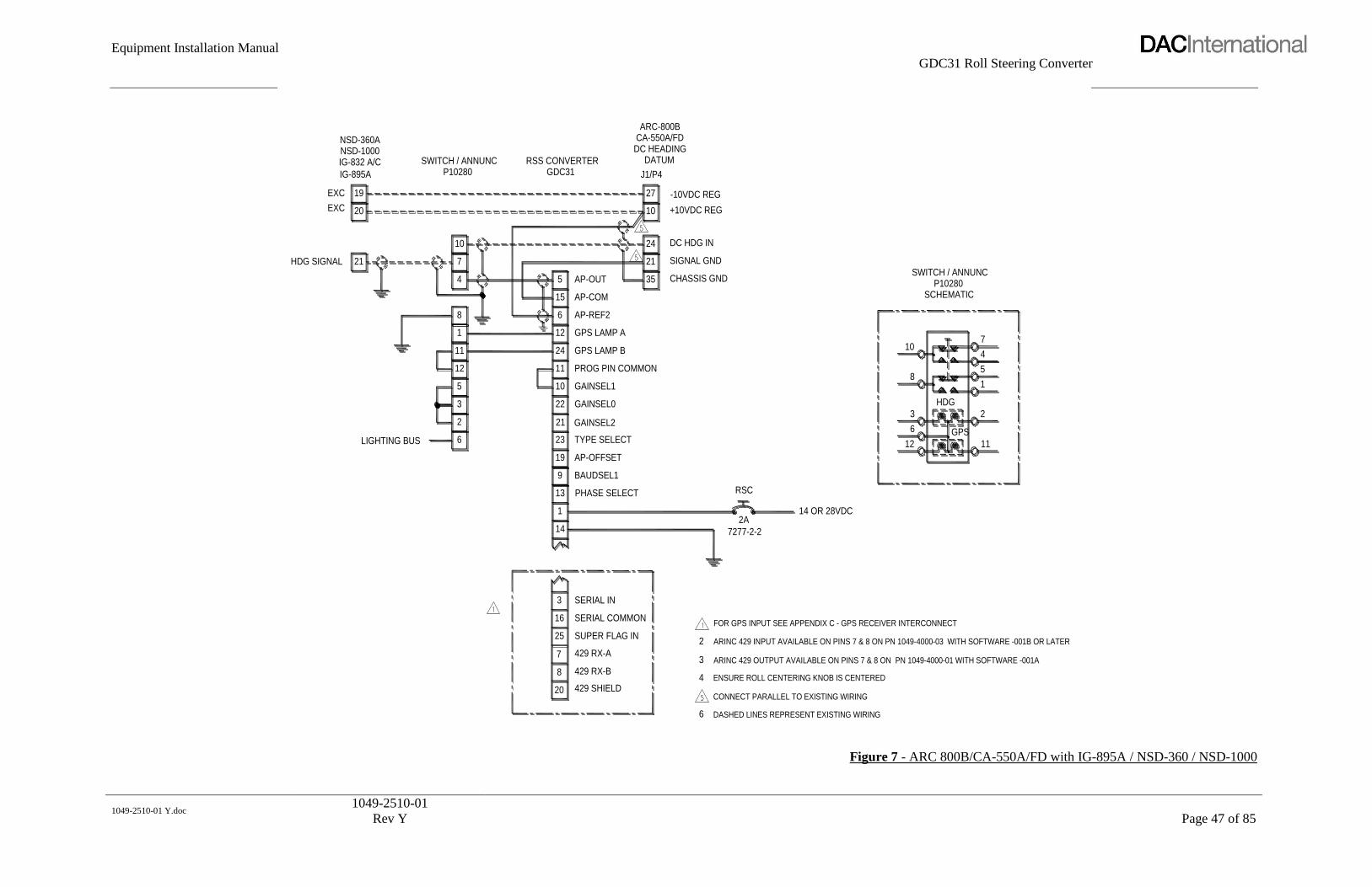
Equipment Installation Manual
GDC31 Roll Steering Converter
1049-2510-01 Y.doc
1049-2510-01
Rev Y
Page 47 of 85
SWITCH / ANNUNCP10280
10
4
7
11
12
1
8
3
2
5
6LIGHTING BUS
21HDG SIGNAL
IG-832 A/C
IG-895A
NSD-1000NSD-360A
20
19EXC
EXC
DASHED LINES REPRESENT EXISTING WIRING
ENSURE ROLL CENTERING KNOB IS CENTERED
ARINC 429 OUTPUT AVAILABLE ON PINS 7 & 8 ON PN 1049-4000-01 WITH SOFTWARE -001A
ARINC 429 INPUT AVAILABLE ON PINS 7 & 8 ON PN 1049-4000-03 WITH SOFTWARE -001B OR LATER
14 OR 28VDC
FOR GPS INPUT SEE APPENDIX C - GPS RECEIVER INTERCONNECT
CONNECT PARALLEL TO EXISTING WIRING20 429 SHIELD
429 RX-A
429 RX-B
SUPER FLAG IN
7
8
25
SERIAL IN
SERIAL COMMON
3
16
14
1
6
3
4
2
2A
7277-2-2
21
35
PROG PIN COMMON
23 TYPE SELECT
BAUDSEL1
PHASE SELECT
AP-OFFSET
9
13
19
GAINSEL0
GAINSEL2
GAINSEL1
22
21
10
AP-REF26
GPS LAMP B
GPS LAMP A
24
11
12
AP-COM
AP-OUT5
15
RSC
SIGNAL GND
CHASSIS GND
ARC-800B
J1/P4
CA-550A/FDDC HEADING
DATUM
10
24
27
GDC31RSS CONVERTER
-10VDC REG
DC HDG IN
+10VDC REG
8
12
3
6
11
1
2
GPS
HDG
P10280SWITCH / ANNUNC
SCHEMATIC
107
4
5
Figure 7 - ARC 800B/CA-550A/FD with IG-895A / NSD-360 / NSD-1000
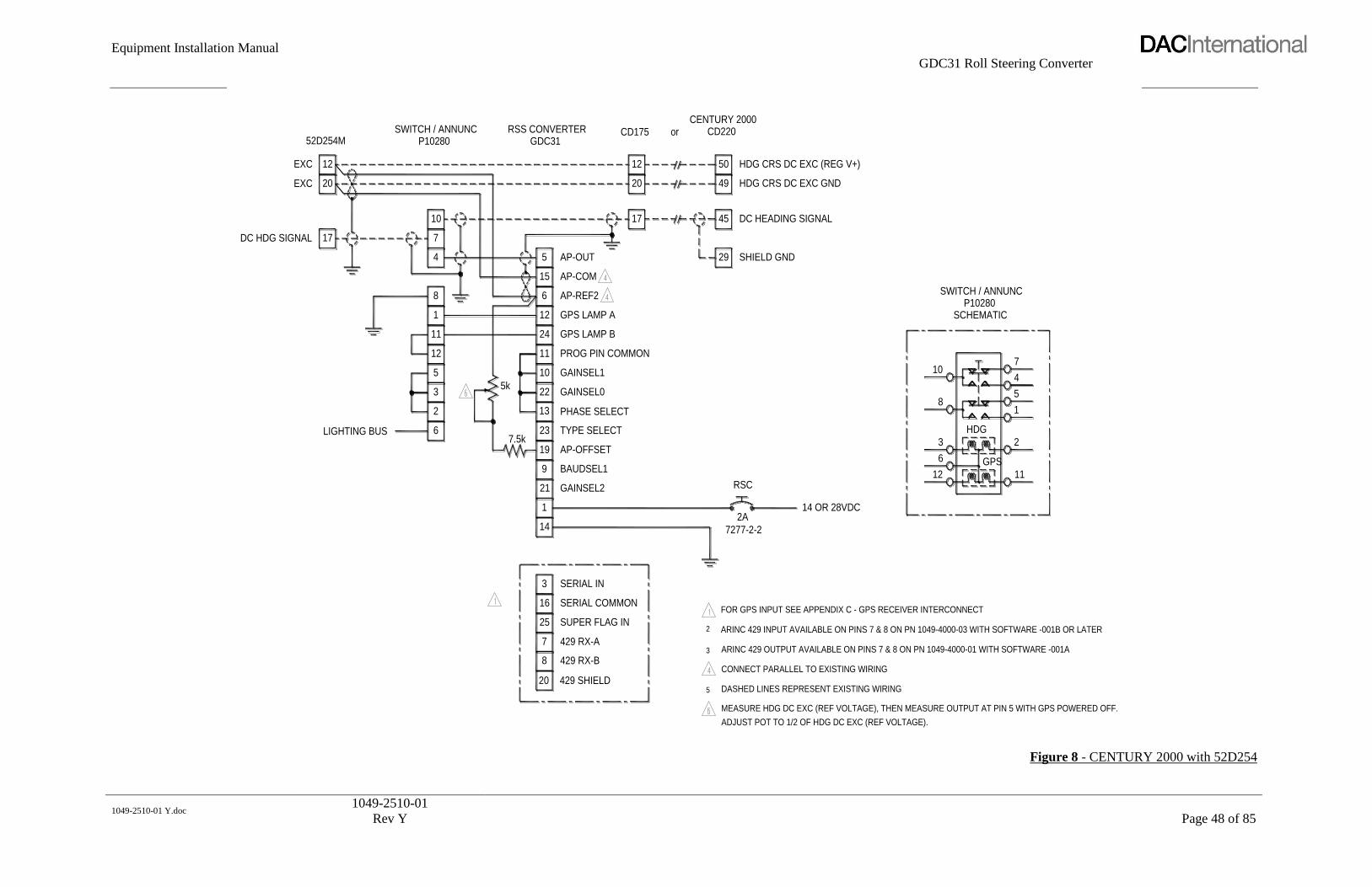
Equipment Installation Manual
GDC31 Roll Steering Converter
1049-2510-01 Y.doc
1049-2510-01
Rev Y
Page 48 of 85
SWITCH / ANNUNC
6LIGHTING BUS
12
3
2
5
1
11
8
DC HDG SIGNAL
P1028052D254M
17
EXC
EXC 20
12
4
7
10
CONNECT PARALLEL TO EXISTING WIRING
FOR GPS INPUT SEE APPENDIX C - GPS RECEIVER INTERCONNECT
ARINC 429 INPUT AVAILABLE ON PINS 7 & 8 ON PN 1049-4000-03 WITH SOFTWARE -001B OR LATER
ARINC 429 OUTPUT AVAILABLE ON PINS 7 & 8 ON PN 1049-4000-01 WITH SOFTWARE -001A
MEASURE HDG DC EXC (REF VOLTAGE), THEN MEASURE OUTPUT AT PIN 5 WITH GPS POWERED OFF.
ADJUST POT TO 1/2 OF HDG DC EXC (REF VOLTAGE).
DASHED LINES REPRESENT EXISTING WIRING
7
20
8
16
25
3
429 RX-A
429 SHIELD
429 RX-B
SERIAL COMMON
SUPER FLAG IN
SERIAL IN
5
3
2
23 TYPE SELECT
14
1
21
9
7.5k19 AP-OFFSET
BAUDSEL1
GAINSEL2
11
5k22
13
10
12
24
6
PROG PIN COMMON
PHASE SELECT
GAINSEL0
GAINSEL1
GPS LAMP A
GPS LAMP B
AP-REF2
7277-2-2
2A
RSC
14 OR 28VDC
GDC31
15
5
AP-COM
AP-OUT
17
20
12
RSS CONVERTER CD175
HDG CRS DC EXC (REG V+)
HDG CRS DC EXC GND
DC HEADING SIGNAL
SHIELD GND29
45
49
50
CENTURY 2000CD220or
HDG
6
12
3
GPS
11
2
SWITCH / ANNUNC
SCHEMATICP10280
8
10
5
1
4
7
Figure 8 - CENTURY 2000 with 52D254
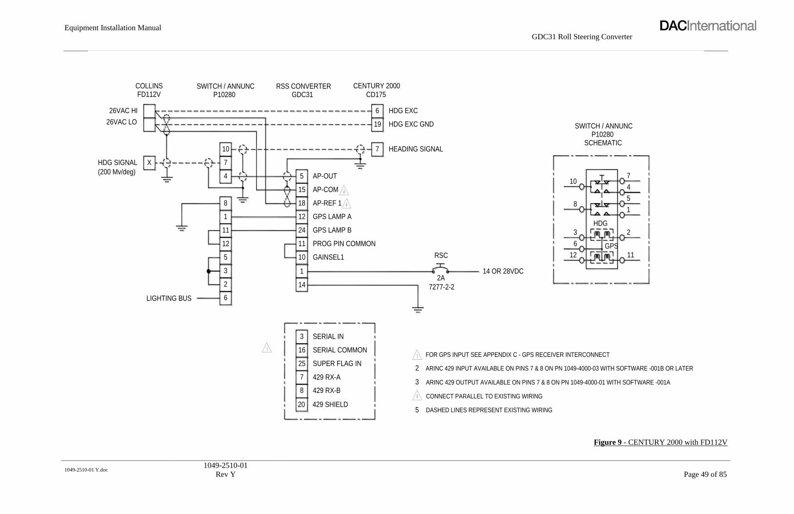
Equipment Installation Manual
GDC31 Roll Steering Converter
1049-2510-01 Y.doc
1049-2510-01
Rev Y
Page 49 of 85
P10280SWITCH / ANNUNC
8
LIGHTING BUS 6
3
2
5
12
11
1
(200 Mv/deg)
HDG SIGNAL X
26VAC LO
26VAC HI
10
4
7
FD112VCOLLINS
CONNECT PARALLEL TO EXISTING WIRING
DASHED LINES REPRESENT EXISTING WIRING20 429 SHIELD
5
14 OR 28VDC
FOR GPS INPUT SEE APPENDIX C - GPS RECEIVER INTERCONNECT
ARINC 429 INPUT AVAILABLE ON PINS 7 & 8 ON PN 1049-4000-03 WITH SOFTWARE -001B OR LATER
ARINC 429 OUTPUT AVAILABLE ON PINS 7 & 8 ON PN 1049-4000-01 WITH SOFTWARE -001A
AP-REF 118
PROG PIN COMMON
3
25
7
8
16 SERIAL COMMON
429 RX-B
429 RX-A
SUPER FLAG IN
SERIAL IN
12
24
11
10
14
1
GAINSEL1
GPS LAMP A
GPS LAMP B
2
3
RSC
7277-2-2
2A
6
19
7
CD175CENTURY 2000
15
5 AP-OUT
AP-COM
RSS CONVERTERGDC31
HEADING SIGNAL
HDG EXC
HDG EXC GND
5
12
6
3
8
GPS
11
1
2
HDG
SCHEMATICP10280
SWITCH / ANNUNC
104
7
Figure 9 - CENTURY 2000 with FD112V

Equipment Installation Manual
GDC31 Roll Steering Converter
1049-2510-01 Y.doc
1049-2510-01
Rev Y
Page 50 of 85
SWITCH / ANNUNC
LIGHTING BUS 6
12
3
2
5
1
11
8
P10280IG-832 A/C
HDG SIGNAL 21
EXC
EXC
20
19
4
7
10
NSD-360ANSD-1000
POWERED OFF, ADJUST POT TO 1/2 OF HDG DC EXC (REF VOLTAGE).
MEASURE HDG DC EXC (REF VOLTAGE). WHILE MEASURING OUTPUT AT PIN 5 WITH GPS RECEIVER
FOR GPS INPUT SEE APPENDIX C - GPS RECEIVER INTERCONNECT
ARINC 429 INPUT AVAILABLE ON PINS 7 & 8 ON PN 1049-4000-03 WITH SOFTWARE -001B OR LATER
ARINC 429 OUTPUT AVAILABLE ON PINS 7 & 8 ON PN 1049-4000-01 WITH SOFTWARE -001A
CONNECT PARALLEL TO EXISTING WIRING
DASHED LINES REPRESENT EXISTING WIRING20
8
7
16
25
3
429 SHIELD
429 RX-B
429 RX-A
SERIAL COMMON
SUPER FLAG IN
SERIAL IN
5
3
2
15 AP-COM
14
1
13
9
7.5k19
23
PHASE SELECT
AP-OFFSET
TYPE SELECT
BAUDSEL1
11
5k 22
21
10
12
24
6
PROG PIN COMMON
GAINSEL0
GAINSEL2
GAINSEL1
GPS LAMP A
GPS LAMP B
AP-REF2
7277-2-2
2A
RSC
14 OR 28VDC
GDC31
5 AP-OUT
17
20
12
RSS CONVERTER CD175
HDG DC EXC GND
HDG DC EXC (REG V+)
DC HEADING SIGNAL
SHIELD GND29
45
49
50
CENTURY 2000CD220or
P10280
23
12
6 GPS
11
SCHEMATIC
8
HDG
104
1
5
7
SWITCH / ANNUNC
Figure 10 - CENTURY 2000 with IG-832A / NSD-360 / NSD-1000
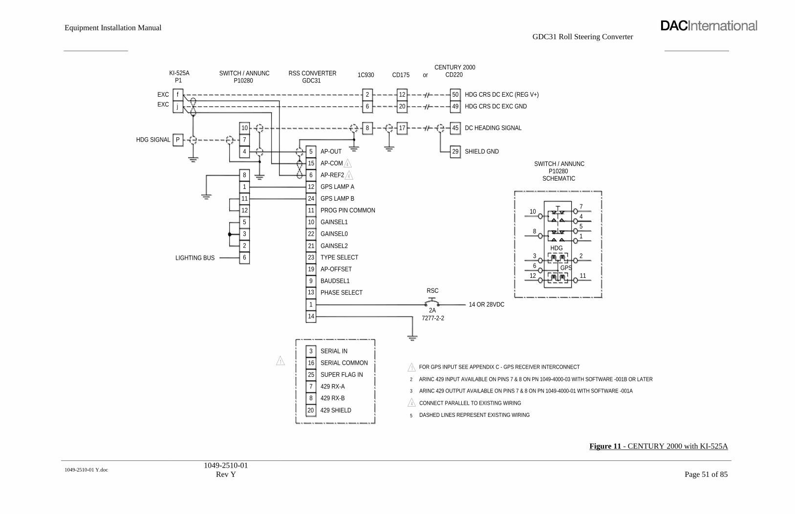
Equipment Installation Manual
GDC31 Roll Steering Converter
1049-2510-01 Y.doc
1049-2510-01
Rev Y
Page 51 of 85
P10280SWITCH / ANNUNC
6LIGHTING BUS
12
3
2
5
1
11
8
P1
HDG SIGNAL P
EXC j
EXC f
4
7
10
KI-525A
ARINC 429 OUTPUT AVAILABLE ON PINS 7 & 8 ON PN 1049-4000-01 WITH SOFTWARE -001A
ARINC 429 INPUT AVAILABLE ON PINS 7 & 8 ON PN 1049-4000-03 WITH SOFTWARE -001B OR LATER
FOR GPS INPUT SEE APPENDIX C - GPS RECEIVER INTERCONNECT
DASHED LINES REPRESENT EXISTING WIRING
CONNECT PARALLEL TO EXISTING WIRING
7
20
8
16
25
3
429 RX-A
429 SHIELD
429 RX-B
SERIAL COMMON
SUPER FLAG IN
SERIAL IN
5
3
2
14 OR 28VDC
HDG CRS DC EXC (REG V+)
DC HEADING SIGNAL
HDG CRS DC EXC GND
PROG PIN COMMON
23 TYPE SELECT
14
1
13
9
19
PHASE SELECT
AP-OFFSET
BAUDSEL1
11
22
21
10
12
24
6
GAINSEL2
GAINSEL1
GAINSEL0
GPS LAMP A
GPS LAMP B
AP-REF2
7277-2-2
RSC
2A
GDC31
15
5
AP-COM
AP-OUT
8
6
2
RSS CONVERTER 1C930
17
20
12
SHIELD GND29
45
49
50
CENTURY 2000CD175 or CD220
SWITCH / ANNUNC
3 2
GPS
12
6
11
SCHEMATICP10280
10
8
HDG
1
5
4
7
Figure 11 - CENTURY 2000 with KI-525A

Equipment Installation Manual
GDC31 Roll Steering Converter
1049-2510-01 Y.doc
1049-2510-01
Rev Y
Page 52 of 85
FOR GPS INPUT SEE APPENDIX C - GPS RECEIVER INTERCONNECT6 429 RX-B8
CONNECT PARALLEL TO EXISTING WIRING (DASHED LINES REPRESENT EXISTING WIRING)
ARINC 429 OUTPUT AVAILABLE ON PINS 7 & 8 ON PN 1049-4000-01 WITH SOFTWARE -001A
ARINC 429 INPUT AVAILABLE ON PINS 7 & 8 ON PN 1049-4000-03 WITH SOFTWARE -001B OR LATER
GROUND BOTH ENDS OF ALL SHIELDING
12 11GPS
20
6
429 SHIELD
5
SETS SCALING TO APPROXIMATELY .0026 (THIS VALUE IS NOT REFERENCED IN THE GAIN TABLES
THIS GAIN STRAPPING AND CONFIGURATION OF THE ISOLATION COUPLER WIRING EFFECTIVELY
IN THE INSTALLATION SECTION OF THIS MANUAL)
IF AIRCRAFT TURNS AWAY FROM TRACK LINE, REMOVE PHASE JUMPER AND RETEST
38 18Ref 1
SCHEMATIC
SWITCH / ANNUNP10280
HDG
8
3
10
LIGHTING BUS
3
1
2
45
7
25
7
16
14
Serial In
Super Flag
429 RX-A
Serial Com
NOTES:
5 10
2
6
3
22
13
1
11
11
12
1
24
15
12
Gain Sel 1 14
Gain Sel 0
Phase Sel
Prog Com
12
11
Lamp B
AP Com
Lamp A
5
6
4
SWITCH / ANNUN
52D54
HDG ERROR
DG EXC 5 KHz
DG EXC 5 KHz
A
E
D
1049-4801-01
7
4
5
10
AP Out
10
9
13
2
1
RSS CONVERTERGDC31P10280
ISOLATIONCOUPLER
31
7277-2-2
2A 12
RSC
14 OR 28VDC
2
9
14
6
1113
10
54
SCHEMATIC
ISOLATIONCOUPLER
1049-4801-01
CD 33 (PIGTAIL)
B ROLL COMMON
E
A
D
DG EXC 5 KHz
DG SIGNAL
DG EXC 5 KHz
IC388/M/PCENTURY
Figure 12 - CENTURY II or III with 52D54 to 1C388/M/P Radio Coupler

Equipment Installation Manual
GDC31 Roll Steering Converter
1049-2510-01 Y.doc
1049-2510-01
Rev Y
Page 53 of 85
8 429 RX-B6CONNECT PARALLEL TO EXISTING WIRING (DASHED LINES REPRESENT EXISTING WIRING)
ARINC 429 OUTPUT AVAILABLE ON PINS 7 & 8 ON PN 1049-4000-01 WITH SOFTWARE -001A
ARINC 429 INPUT AVAILABLE ON PINS 7 & 8 ON PN 1049-4000-03 WITH SOFTWARE -001B OR LATER
GROUND BOTH ENDS OF ALL SHIELDING
12 11GPS
20 429 SHIELD
6
5
IF AIRCRAFT TURNS AWAY FROM TRACK LINE, REMOVE PHASE JUMPER AND RETEST
IN THE INSTALLATION SECTION OF THIS MANUAL)
THIS GAIN STRAPPING AND CONFIGURATION OF THE ISOLATION COUPLER WIRING EFFECTIVELY
SETS SCALING TO APPROXIMATELY .0026 (THIS VALUE IS NOT REFERENCED IN THE GAIN TABLES
FOR GPS INPUT SEE APPENDIX C - GPS RECEIVER INTERCONNECT
188 3
P10280SWITCH / ANNUN
SCHEMATIC
HDG
8
3
10
LIGHTING BUS
3
1
2
45
7
25
7
16
14
Serial In
Super Flag
429 RX-A
Serial Com
NOTES:
105
6
3
2
1
13
11
22
11
12
1
24
15
12
14Gain Sel 1
Phase Sel
Gain Sel 0
Prog Com 11
12
Lamp B
AP Com
Lamp A
5
6
4
SWITCH / ANNUN
4000C
HDG ERROR A
B
E
D
52D541049-4801-01
7
4
5
10
Ref 1
AP Out
10
9
13
2
1
GDC31RSS CONVERTER
P10280 COUPLERISOLATION
1 3
2A
7277-2-2
12
RSC
14 OR 28VDC
9
2
14
1311
10
5
6
4
1049-4801-01COUPLERISOLATION
SCHEMATIC
CONSOLE / AMPCONSOLE / AMP
D D
J
A
L
J
A
L
ROLL COMMON
DG EXCITATION
DG SIGNAL
DG EXCITATION
CENTURY IIICENTURY II1C385 OR 1D395
Figure 13 - CENTURY II / III with 4000C DG / 52D54 to 1C385 / 1D395 Console / Amp

Equipment Installation Manual
GDC31 Roll Steering Converter
1049-2510-01 Y.doc
1049-2510-01
Rev Y
Page 54 of 85
DASHED LINES REPRESENT EXISTING WIRING520 429 SHIELD
1112
GROUND BOTH ENDS OF ALL SHIELDING
IF AIRCRAFT TURNS AWAY FROM TRACK LINE, REMOVE PHASE JUMPER AND RETEST
CONNECT PARALLEL TO EXISTING WIRING
ARINC 429 OUTPUT AVAILABLE ON PINS 7 & 8 ON PN 1049-4000-01 WITH SOFTWARE -001A
ARINC 429 INPUT AVAILABLE ON PINS 7 & 8 ON PN 1049-4000-03 WITH SOFTWARE -001B OR LATER
FOR GPS INPUT SEE APPENDIX C - GPS RECEIVER INTERCONNECT
3188
SCHEMATIC
SWITCH / ANNUN
LIGHTING BUS
63
8
104
HDG
GPS
2
15
7
P10280
429 RX-B
429 RX-A
8
7
Serial Com
Super Flag2525
16
3
2
Serial In3
14
5
6
3
2
11
12
1
13
Phase Sel
1
13
Prog Com
Gain Sel 0
11
22
11
14
Lamp B24
AP Com15
Lamp A12
5
6
4
HE
AD
ING
BBY
Z C C
EX
C.
EC
X A
H D
E
A
P201
D
23 H
24 J
26 N
22 G
25
P2
M
J2
WILCOX1041A
COLLINSPN 101 KPI-550
KINGor or
SPERRYRD-444-447
or
1049-4801-01
10
4
7
AP Out
Ref 1
5
9
10
12
2
1
RSS CONVERTERGDC31
SWITCH / ANNUNP10280
ISOLATIONCOUPLER
31
2A
7277-2-2 12
14 OR 28VDC
RSC
2
9
14
6
1113
10
45
1049-4801-01
SCHEMATIC
COUPLERISOLATION
CONSOLE/AMP CONSOLE/AMP
HEADING ERROR
HDG COM
5 KHz EXCITATION
5 KHz EXCITATION
AA
J
D
L
J
D
L
CENTURYIC385
CENTURYID395
or
Figure 14 - CENTURY II / III with ARINC HSI to 1C385 / 1D395 Console/Amp

Equipment Installation Manual
GDC31 Roll Steering Converter
1049-2510-01 Y.doc
1049-2510-01
Rev Y
Page 55 of 85
DASHED LINES REPRESENT EXISTING WIRING20 429 SHIELD
1112 5
IF AIRCRAFT TURNS AWAY FROM TRACK LINE, REMOVE PHASE JUMPER AND RETEST
GROUND BOTH ENDS OF ALL SHIELDING
ARINC 429 INPUT AVAILABLE ON PINS 7 & 8 ON PN 1049-4000-03 WITH SOFTWARE -001B OR LATER
ARINC 429 OUTPUT AVAILABLE ON PINS 7 & 8 ON PN 1049-4000-01 WITH SOFTWARE -001A
CONNECT PARALLEL TO EXISTING WIRING
FOR GPS INPUT SEE APPENDIX C - GPS RECEIVER INTERCONNECT
3188
SCHEMATIC
SWITCH / ANNUN
LIGHTING BUS
10
36
8
14
3
16
2525
7
8
4
GPS
HDG
2
51
7
P10280
429 RX-A
429 RX-B
Serial Com
Super Flag3
2
Serial In
12
15
24
22
11
13
1
5
6
3
2
11
12
1
13
Phase Sel
Gain Sel 0
Prog Com 11
14
Lamp B
AP Com
Lamp A
5
6
4
19C
HE
AD
ING
EX
C.
C 31
H 18
H 33
J1
IN-831ABENDIX
1049-4801-01
5
10
4
7
AP Out
Ref 1
9
10
12
2
1
GDC31RSS CONVERTERSWITCH / ANNUN
P10280 COUPLERISOLATION
2A
7277-2-2
14 OR 28VDC
RSC
12
2
9
14
1113
10
6
54
COUPLER1049-4801-01SCHEMATIC
ISOLATION
CONSOLE/AMP CONSOLE/AMP
HEADING ERROR
ROLL EXCITATION
ROLL EXCITATION
HDG COM
A A
E
F
D
E
F
D
1
CENTURYIC385
CENTURYID395
3
Figure 15 - CENTURY II / III with IN-831A HSI to 1C385 / 1D395 CONSOLE/AMP

Equipment Installation Manual
GDC31 Roll Steering Converter
1049-2510-01 Y.doc
1049-2510-01
Rev Y
Page 56 of 85
8 429 RX-B6 4 DASHED LINES BETWEEN HSI AND AUTOPILOT REPRESENT EXISTING WIRING
GROUND BOTH ENDS OF ALL SHIELDING
CONNECT PARALLEL TO EXISTING WIRING
IF AIRCRAFT TURNS AWAY FROM TRACK LINE, REMOVE PHASE JUMPER THEN RETEST
12GPS
11 429 SHIELD20
ARINC 429 OUTPUT AVAILABLE ON PINS 7 & 8 ON PN 1049-4000-01 WITH SOFTWARE -001A
ARINC 429 INPUT AVAILABLE ON PINS 7 & 8 ON PN 1049-4000-03 WITH SOFTWARE -001B OR LATER
FOR GPS INPUT SEE APPENDIX C - GPS RECEIVER INTERCONNECT
10AP Out
5
SCHEMATICP10280
SWITCH / ANNUN
LIGHTING BUS
8
3
10
1
HDG
2
45
73 Serial In
25 Super Flag
429 RX-A7
Serial Com16
3
2
14
1
12
6
2
3
5
1
11
8
615 AP Com
Gain Sel 0
Phase Sel13
22
Prog Com11
14
11
13
12 Lamp A
Lamp B24
Ref 118
4
5
3
IU445-004-11
HEADING ERROR 21
IU445-003-17
EXC
EXC 20
19
NSD-1000NSD-360A
ISOLATIONSWITCH / ANNUN RSS CONVERTERGDC31
10
4
7
P10280
12
9
1
2
COUPLER1049-4801-01
14 OR 28VDC
7277-2-2
2A12
RSC
2
9
1
14
6
1113
10
45
3
COUPLER
SCHEMATIC1049-4801-01
ISOLATION
CENTURYCENTURY
HEADING COMMON
A HEADING ERROR
B
ROLL EXCITATION
ROLL EXCITATION
CD 33 PIGTAIL
E
D
IC388-2 IC388-2CD 33
Figure 16 - CENTURY II / III with NSD-360A / NSD-1000 to 1C388-2 Radio Coupler
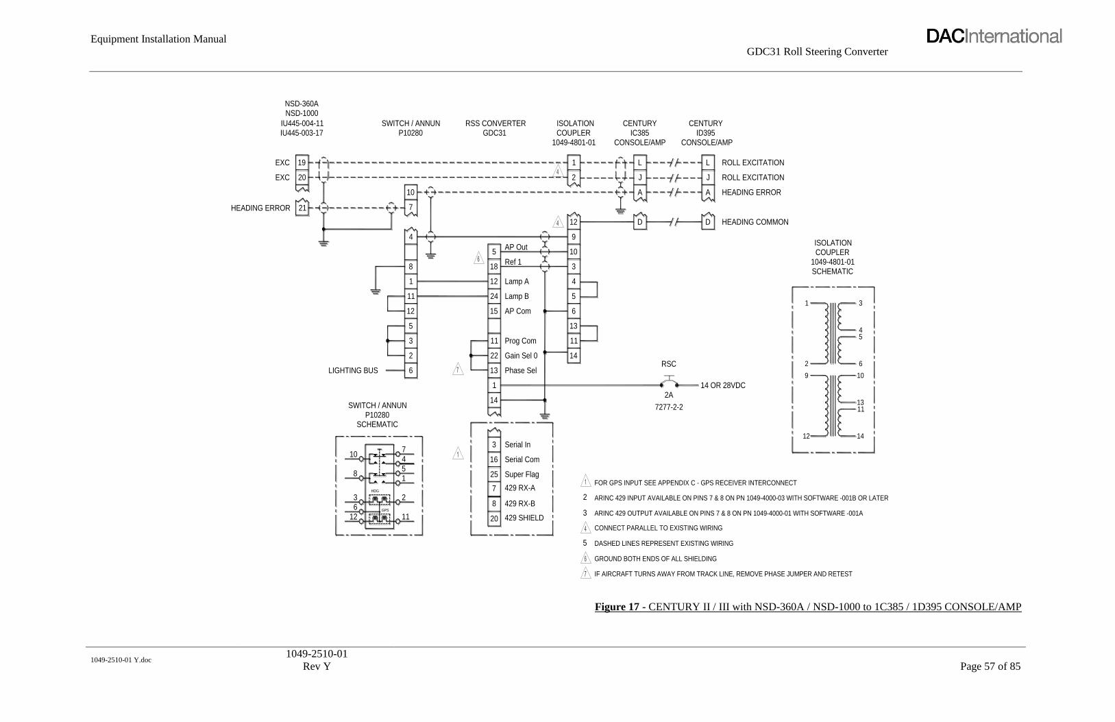
Equipment Installation Manual
GDC31 Roll Steering Converter
1049-2510-01 Y.doc
1049-2510-01
Rev Y
Page 57 of 85
8 429 RX-B6
IF AIRCRAFT TURNS AWAY FROM TRACK LINE, REMOVE PHASE JUMPER AND RETEST
ARINC 429 OUTPUT AVAILABLE ON PINS 7 & 8 ON PN 1049-4000-01 WITH SOFTWARE -001A
CONNECT PARALLEL TO EXISTING WIRING
GROUND BOTH ENDS OF ALL SHIELDING
DASHED LINES REPRESENT EXISTING WIRING
12GPS
11 429 SHIELD20
5
3
ARINC 429 INPUT AVAILABLE ON PINS 7 & 8 ON PN 1049-4000-03 WITH SOFTWARE -001B OR LATER
FOR GPS INPUT SEE APPENDIX C - GPS RECEIVER INTERCONNECT
10AP Out
5
SCHEMATICP10280
SWITCH / ANNUN
LIGHTING BUS
8
3
10
1
HDG
2
45
73 Serial In
25 Super Flag
429 RX-A7
Serial Com16
2
14
1
12
6
2
3
5
1
11
8
615 AP Com
Gain Sel 0
Phase Sel13
22
Prog Com11
14
11
13
12 Lamp A
Lamp B24
Ref 118
4
5
3
IU445-004-11
HEADING ERROR 21
IU445-003-17
EXC
EXC 20
19
NSD-1000NSD-360A
ISOLATIONSWITCH / ANNUN RSS CONVERTERGDC31
10
4
7
P10280
12
9
1
2
COUPLER1049-4801-01
COUPLER1049-4801-01SCHEMATIC
9
14 OR 28VDC
7277-2-2
2A
12
RSC 2
1
10
11
14
13
6
45
3
ISOLATION
CENTURY CENTURY
CONSOLE/AMP
HEADING ERROR
HEADING COMMON
ROLL EXCITATION
ROLL EXCITATION
A A
D D
CONSOLE/AMP
J
L
IC385
J
L
ID395
Figure 17 - CENTURY II / III with NSD-360A / NSD-1000 to 1C385 / 1D395 CONSOLE/AMP

Equipment Installation Manual
GDC31 Roll Steering Converter
1049-2510-01 Y.doc
1049-2510-01
Rev Y
Page 58 of 85
3 2 8 429 RX-B CONNECT TO SINGLE SOURCE ONLY - RS232 OR ARINC 4292
CONNECT PARALLEL TO EXISTING WIRING
DASHED LINES REPRESENT EXISTING WIRING
IF AIRCRAFT TURNS AWAY FROM TRACK LINE, REMOVE PHASE JUMPER AND RETEST
FOR GPS INPUT SEE APPENDIX C - GPS RECEIVER INTERCONNECT
126 GPS
1120 429 SHIELD
4
ARINC 429 INPUT AVAILABLE ON PINS 7 & 8 ON -03 MODEL WITH SOFTWARE -001B OR LATER
ARINC 429 OUTPUT AVAILABLE ON PINS 7 & 8 ON -01 MODEL WITH SOFTWARE -001A
ROLL EXC
HDG ERROR
SIG REF
CENTURY
8
10
5
HDG
1
74
SWITCH / ANNUNP10280
SCHEMATIC
5
LIGHTING BUS
2
6
3
12
11
1
8
1
3 Serial In
25
7
16
Super Flag
429 RX-A
Serial Com
147277-2-2
2A
23 Type Sel 0
22
13
11
Gain Sel 0
Phase Sel
Prog Com
19
24
12
18
Offset
Lamp B
Lamp A
Ref 1
RSC
8
7
SWITCH / ANNUN
SN3500SN3308 P10280
HDG ERROR
23EXC
26
P2
4
7
10
10
26
P2
GDC31 COUPLER IC388-2
5 AP Out
A
4
6
2
3
5
1
D
E
CD 33 PIGTAIL
ISOLATION
EXISTING
RSS CONVERTER CENTURY
SCHEMATIC
IC388-2 TO DG
IC388-2 TO DGIC388-2 TO DG
IC388-2 TO AMP
14 OR 28VDC
8 4 [B]
[23]
[26]3308 HDG
EXC3308
6
7
[A]3
10k
2 [E]
5
10k
1 [D]
IC388-2
HDG COMB
CD 33
COUPLER
EXISTING
ISOLATION
Figure 18 - CENTURY III with SN3308 / SN3500 to 1C388-2 Radio Coupler

Equipment Installation Manual
GDC31 Roll Steering Converter
1049-2510-01 Y.doc
1049-2510-01
Rev Y
Page 59 of 85
RSS CONVERTERKPI-550
KING
P201
H
C
Y
Z
XH
EA
DIN
GE
XC
.A
C
B
E
D
COLLINSPN 101
or
4
LIGHTING BUS 6
12
2
3
5
1
11
8
22A
C
B
24
23
E
D
26
P2
25
G
J
H
N
J2
M
or WILCOX1041A
SPERRYRD-444-447
or
7
10
P10280SWITCH / ANNUN
ARINC 429 OUTPUT AVAILABLE ON PINS 7 & 8 ON PN 1049-4000-01 WITH SOFTWARE -001A16 Serial Com
IF 5 KHZ EXC AT PIN 40 ON ID496 COMPUTER, JUMPER PIN 13 TO PIN 11
IF 5 KHZ EXC AT PIN 39 ON ID496 COMPUTER, DO NOT JUMPER PIN 13 TO PIN 11
NOTE: ID496 COMPUTER MUST BE ARINC TYPE ID496-X1XX2
DASHED LINES REPRESENT EXISTING WIRING
CONNECT PARALLEL TO EXISTING WIRING
429 RX-A
429 RX-B
Super Flag
429 SHIELD20
7
8
25
5
ARINC 429 INPUT AVAILABLE ON PINS 7 & 8 ON PN 1049-4000-03 WITH SOFTWARE -001B OR LATER
SCHEMATICP10280
SWITCH / ANNUN
FOR GPS INPUT SEE APPENDIX C - GPS RECEIVER INTERCONNECT
AP Out5
Type Sel 0
3 Serial In
14
1
23
3
2
Prog Com
Phase Sel
AP Com
Gain Sel 0
15
22
11
13
12
24
18
Lamp A
Lamp B
Ref 1
RSC
14 OR 28VDC2A
7277-2-2
612
3HDG
10
8
CENTURY IV
43
42
ID496 COMPUTERGDC31
AC HDG ERR IN
5KHz EXCITATION
SIG COM
GPS
11
2
451
7
Figure 19 - CENTURY IV with ARINC HSI
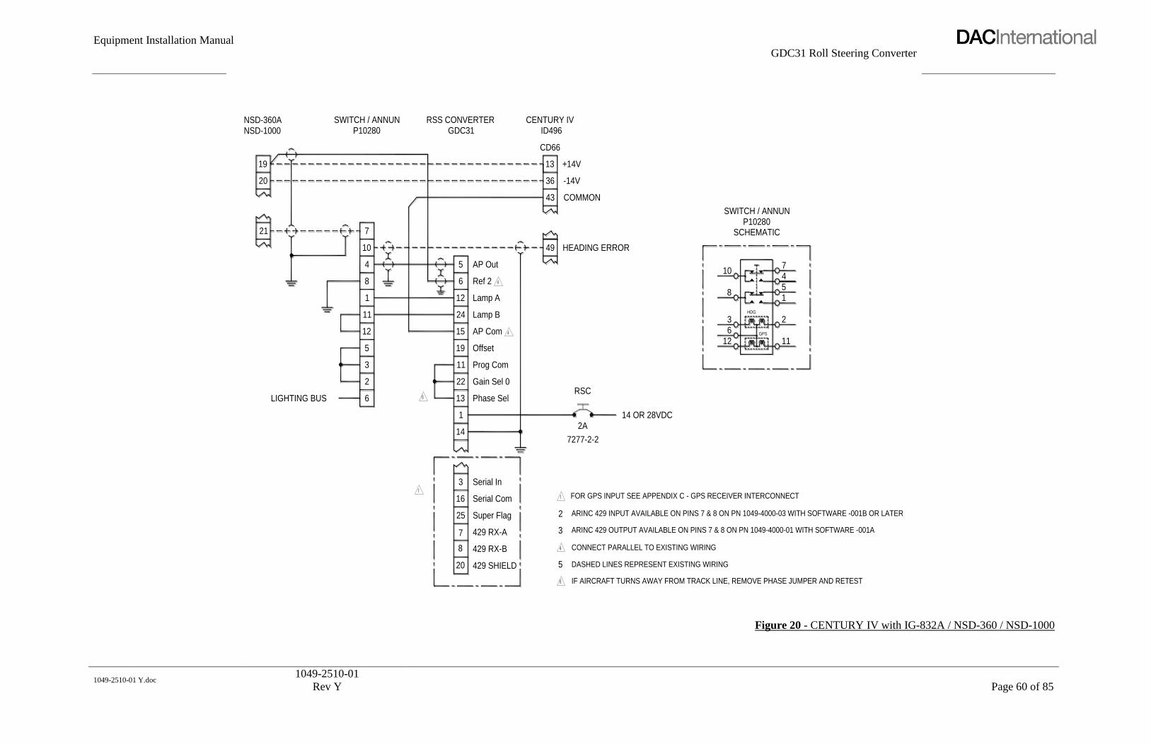
Equipment Installation Manual
GDC31 Roll Steering Converter
1049-2510-01 Y.doc
1049-2510-01
Rev Y
Page 60 of 85
3
LIGHTING BUS 6
2
NSD-1000NSD-360A
20
21
19
8
5
12
1
11
7
4
10
SWITCH / ANNUNP10280
IF AIRCRAFT TURNS AWAY FROM TRACK LINE, REMOVE PHASE JUMPER AND RETEST
FOR GPS INPUT SEE APPENDIX C - GPS RECEIVER INTERCONNECT
12
10
ARINC 429 INPUT AVAILABLE ON PINS 7 & 8 ON PN 1049-4000-03 WITH SOFTWARE -001B OR LATER
ARINC 429 OUTPUT AVAILABLE ON PINS 7 & 8 ON PN 1049-4000-01 WITH SOFTWARE -001A
DASHED LINES REPRESENT EXISTING WIRING
11 Prog Com
7277-2-2
CONNECT PARALLEL TO EXISTING WIRING8 429 RX-B
429 SHIELD20 5
Phase Sel
Gain Sel 0
Serial Com
Super Flag
429 RX-A
Serial In
7
25
3
16
1
14
13
22
3
2
14 OR 28VDC2A
RSC
CENTURY IV
-14V
HEADING ERROR
COMMON
+14V
36
AP Com
Lamp B
Lamp A
AP Out
Ref 26
19
15
12
24
Offset
5
49
43
RSS CONVERTERGDC31
CD66
13
ID496
4
GPS
36
8
HDG
2
11
15
SCHEMATICP10280
SWITCH / ANNUN
7
Figure 20 - CENTURY IV with IG-832A / NSD-360 / NSD-1000

Equipment Installation Manual
GDC31 Roll Steering Converter
1049-2510-01 Y.doc
1049-2510-01
Rev Y
Page 61 of 85
N EW W IR ES FR O M AN N SW ITC H AN D ISO C O U PLER TO H SI429 SH IELD20
D ISC O N N EC T EN D AT H SI AN D C O N N EC T AT AN N SW ITC H AN D ISO C O U PLER TH EN R U N
D ASH ED LIN ES AT AU TO PILO T R EPR ESEN T EXISTIN G W IR IN G W H IC H O R IG IN ALLY R U N TO H SI
FO R G PS IN PU T SEE APPEN D IX C - G PS R EC EIVER IN TER C O N N EC T
AR IN C 429 O U TPU T AVAILABLE O N P IN S 7 & 8 O N PN 1049-4000-01 W ITH SO FTW AR E -001A
AR IN C 429 IN PU T AVAILABLE O N P IN S 7 & 8 O N PN 1049-4000-03 W ITH SO FTW AR E -001B O R LATER
FLIG H T C M PTR
562A-5M 5
8 18 R ef 1
LIG H TIN G BU S
Seria l C om
429 R X-A
Super F lag
429 R X-B
Seria l In
8
7
2525
16
3
4
3
2
Prog C om
G ain Sel 0
Phase Sel
AP C om
Lam p B
Lam p A
6
2
3
1
13
22
11
5
12
11
1
14
15
24
12
14
11
13
6
5
4
SW ITC H / AN N U N
J2
26VAC (H )
26VAC (C )
H D G ER R O R (C )
H D G ER R O R (H )
4
16
5
15
H SI
331A-6R
1049-4801-01
AP O ut
10
4
5
7
9
3
10
12
R SS C O N VER TER
P10280 G D C 31 C O U PLER
ISO LATIO N
5
2A
7277-2-2
R SC
14 O R 28VD C
3
12
6
8
12
2
G PS
11
H D G
1 2
9
11
14
13
10
6
ISO LATIO N
1049-4801-01
C O U PLER
SW ITC H / AN N U N
33 H D G ER R O R (H )
S IG N AL R EF23
10G PS
H DG 7
4
P102801
54
3
Figure 21 - COLLINS AP105 with 331A-6R

Equipment Installation Manual
GDC31 Roll Steering Converter
1049-2510-01 Y.doc
1049-2510-01
Rev Y
Page 62 of 85
SIG REF
EXCITATION
HDG ERROR
GROUND
1
429 RX-A7
429 SHIELD
429 RX-B
20
85
Serial In
Serial Com
Super Flag
16
25
3
14
2
3
SWITCH / ANNUNP10280
26VAC EXCITATION a
SIG REF
HDG ERROR
LIGHTING BUS
5
2
6
3
11
12
1
X
B
8
4
7
10
FD112C/V
J2
29
Offset
Prog Com
Gain Sel 1
Phase Sel
Lamp A
Lamp B
19
10
13
11
24
15
12
26
Ref 1
AP Out
18
5
25
24
RSS CONVERTERGDC31
J1
913K-1/1A
14 OR 28VDC
ARINC 429 INPUT AVAILABLE ON PINS 7 & 8 ON PN 1049-4000-03 WITH SOFTWARE -001B OR LATER
ARINC 429 OUTPUT AVAILABLE ON PINS 7 & 8 ON PN 1049-4000-01 WITH SOFTWARE -001A
IF AIRCRAFT TURNS AWAY FROM TRACK LINE, REMOVE PHASE JUMPER AND RETEST
FOR GPS INPUT SEE APPENDIX C - GPS RECEIVER INTERCONNECT
CONNECT PARALLEL TO EXISTING WIRING
DASHED LINES REPRESENT EXISTING WIRING
7277-2-2
2A
SWITCH / ANNUN
SCHEMATIC
RSC
612
3
10
8
GPS
HDG
11
2
4
15
7
P10280
Figure 22 - COLLINS AP106 with FD112C/V

Equipment Installation Manual
GDC31 Roll Steering Converter
1049-2510-01 Y.doc
1049-2510-01
Rev Y
Page 63 of 85
SWITCH / ANNUNC
4(333.3 mv/deg)
3
LIGHTING BUS 6
2
5
11
12
8
1
HDG/CRS REF
HDG ERROR 4
1
+15VDC
-15VDC 2
3
P1
10
7
P10280
1U262-042-2
4000C-15
FOR GPS INPUT SEE APPENDIX C - GPS RECEIVER INTERCONNECT
ARINC 429 INPUT AVAILABLE ON PINS 7 & 8 ON PN 1049-4000-03 WITH SOFTWARE -001B OR LATER
ARINC 429 OUTPUT AVAILABLE ON PINS 7 & 8 ON PN 1049-4000-01 WITH SOFTWARE -001A
CONNECT PARALLEL TO EXISTING WIRING
DASHED LINES REPRESENT EXISTING WIRING
20 429 SHIELD
SERIAL IN
429 RX-A
429 RX-B
SUPER FLAG IN
SERIAL COMMON16
7
8
25
3
5
2
3
5 AP-OUT
GAINSEL022
GAINSEL2
AP-OFFSET
BAUDSEL1
PHASE SELECT
TYPE SELECT
9
1
14
13
23
19
21
AP-REF2
AP-COM
GPS LAMP A
GAINSEL1
GPS LAMP B
PROG PIN COMMON
10
11
24
6
12
15
7277-2-2
2A
RSC
14 OR 28VDC
27
P1401GDC31
1049-4000-03
RSS CONVERTER
DG HDG DATUM
-15 VDC REG
+15 VDC REG
HDG REF
17
19
18
P1402
KAP-140
AP COMPUTER
P10280
12
6 GPS
11
SCHEMATIC
3
8
104
1
2
5
HDG
7
SWITCH / ANNUNC
Figure 23 - KING KAP 140 with 4000C-15 DG

Equipment Installation Manual
GDC31 Roll Steering Converter
1049-2510-01 Y.doc
1049-2510-01
Rev Y
Page 64 of 85
SWITCH / ANNUNC
(600 mv/deg) 4
3
LIGHTING BUS 6
2
5
12
11
8
1
HDG/CRS REF
HDG ERROR P
S
-15VDC
+15VDC
Y
f
P1
10
7
P10280
KI-525A
IF TURNS ARE SLUGGISH, INSTALL THIS JUMPER
USE THIS JUMPER ONLY ON -03 MODEL WITH SOFTWARE -001B OR LATER
FOR GPS INPUT SEE APPENDIX C - GPS RECEIVER INTERCONNECT
ARINC 429 INPUT AVAILABLE ON PINS 7 & 8 ON PN 1049-4000-03 WITH SOFTWARE -001B OR LATER
ARINC 429 OUTPUT AVAILABLE ON PINS 7 & 8 ON PN 1049-4000-01 WITH SOFTWARE -001A
CONNECT PARALLEL TO EXISTING WIRING
DASHED LINES REPRESENT EXISTING WIRING
429 SHIELD20
SERIAL COMMON
SUPER FLAG IN
429 RX-B
429 RX-A
SERIAL IN
16
7
8
25
3
6
3
4
-15 VDC REG
+15 VDC REG
AP-OUT5
22 GAINSEL0
TYPE SELECT
PHASE SELECT
BAUDSEL1
AP-OFFSET
GAINSEL2
9
1
14
13
23
19
21
PROG PIN COMMON
GPS LAMP B
GAINSEL1
GPS LAMP A
AP-COM
AP-REF2
10
11
24
6
12
15
2A
7277-2-2
RSC
14 OR 28VDC
27
KAP-140
AP COMPUTER
P1401GDC31
RSS CONVERTER
1049-4000-03
HDG REF
HSI HDG DATUM2
19
18
P1
KG102A
P10280
12
6 GPS
11
SCHEMATIC
3
8
104
5
2
1
HDG
7
SWITCH / ANNUNC
Figure 24 - KING KAP 140 with KI-525A

Equipment Installation Manual
GDC31 Roll Steering Converter
1049-2510-01 Y.doc
1049-2510-01
Rev Y
Page 65 of 85
BENDIX/KING
jSIGNAL GROUND
LIGHTING BUS
HEADING ERROR
HDG/CRS RETURN
P
S
7
20
8
16
25
3
429 RX-A
429 SHIELD
429 RX-B
Super Flag
Serial Com
Serial In
12
6
3
2
5
4
11
1
8
10
7
AP Com15
21
14
1
11
19
Gain Sel 2
Prog Com
Offset
5
12
24
6
AP Out
Lamp A
Lamp B
Ref 2
KI-525 / 525ABENDIX/KING
EXCITATION +15V
EXCITATION -15V
f
Y
P1
SWITCH / ANNUNP10280 GDC31
RSS CONVERTER
1049-4000-03
CF
THIS DRAWING SHOULD BE USED FOR SYSTEMS INCORPORATING BENDIX/KING KCS55
ARINC 429 OUTPUT AVAILABLE ON PINS 7 & 8 ON PN 1049-4000-01 WITH SOFTWARE -001A
ARINC 429 INPUT AVAILABLE ON PINS 7 & 8 ON PN 1049-4000-03 WITH SOFTWARE -001B OR LATER
FOR GPS INPUT INTERCONNECT SEE APPENDIX C - GPS RECEIVER INTERCONNECT
SCHEMATIC
SWITCH / ANNUN
USE THIS JUMPER ONLY ON 1049-4000-03 MODEL WITH SOFTWARE -001B OR LATER
RADIO COUPLER
TO AC AUTOPILOT SYSTEM /
DASHED LINES REPRESENT EXISTING WIRING
CONNECT PARALLEL TO EXISTING WIRING
IF TURNS ARE SLUGGISH, INSTALL THIS JUMPER
SYSTEMS WITH KA 52 OR KA 57 AUTOPILOT ADAPTERS
NOTE:
14 OR 28VDC
7277-2-2
RSC
2A
10
8 6
F
612
8
3
10
GPS
11
HDG
5
2
1
47
P10280
KA-57
5
K
or
KA-52
2
1
BENDIX/KING
Figure 25 - KING KCS55 SYSTEM with KI-525 / 525A and KA-52 / KA-57

Equipment Installation Manual
GDC31 Roll Steering Converter
1049-2510-01 Y.doc
1049-2510-01
Rev Y
Page 66 of 85
LIGHTING BUS
P2
26
4
P1
DC HDG DATUM
(600 mv/deg)
HDG/CRS RETURN
P2
26
1
P2
SN3308 SN3500
WITH KA52 OR KA57 AUTOPILOT ADAPTERS
NOTE: THIS DRAWING SHOULD BE USED FOR SYSTEMS INCORPORATING BENDIX/KING KCS55 SYSTEMS
DASHED LINES BETWEEN KA-92 AND HSI AND DG REPRESENT EXISTING WIRING - DO NOT REMOVE
ARINC 429 OUTPUT AVAILABLE ON PINS 7 & 8 ON PN 1049-4000-01 WITH SOFTWARE -001A
ARINC 429 INPUT AVAILABLE ON PINS 7 & 8 ON PN 1049-4000-03 WITH SOFTWARE -001B OR LATER
USE THIS JUMPER ONLY ON -03 MODEL WITH SOFTWARE -001B OR LATER
FOR GPS INPUT SEE APPENDIX C - GPS RECEIVER INTERCONNECT
IF TURNS ARE SLUGGISH, INSTALL THIS JUMPER
429 SHIELD20
SUPER FLAG IN
PHASE SELECT
TYPE SELECT
16 SERIAL COM
429 RX-A
429 RX-B
7
8
25
SERIAL IN3
6
13
14
1
AP-OFFSET
BAUDSEL1
19
9
23
4
5
3
14 OR 28VDC
RSC 2A
7277-2-2
6
12
3
GPS
HDG
11
2
DIRECTIONAL
2
PROG PIN COMMON12
3
2
5
1
11
8
11
GAINSEL0
GAINSEL2
GAINSEL1
22
21
10
GPS LAMP A
GPS LAMP B
AP-REF2
12
24
6
10
4
7
AP-OUT
AP-COM
5
15
HDG/CRS SEL LO
HDG SEL HIF
6
C
P10280SWITCH / ANNUNC
GDC31RSS CONVERTER
1049-4000-03
J101A/P ADAPTER
KA-52
+15 VDC REGH
SWITCH / ANNUNC
SCHEMATIC
8
10
P10280
SIGNAL GNDY
5
1
4
7
GYRO
KG-102A
Figure 26 - KING KCS55 SYSTEM with KG-102A & SN3308 / SN3500 HSI
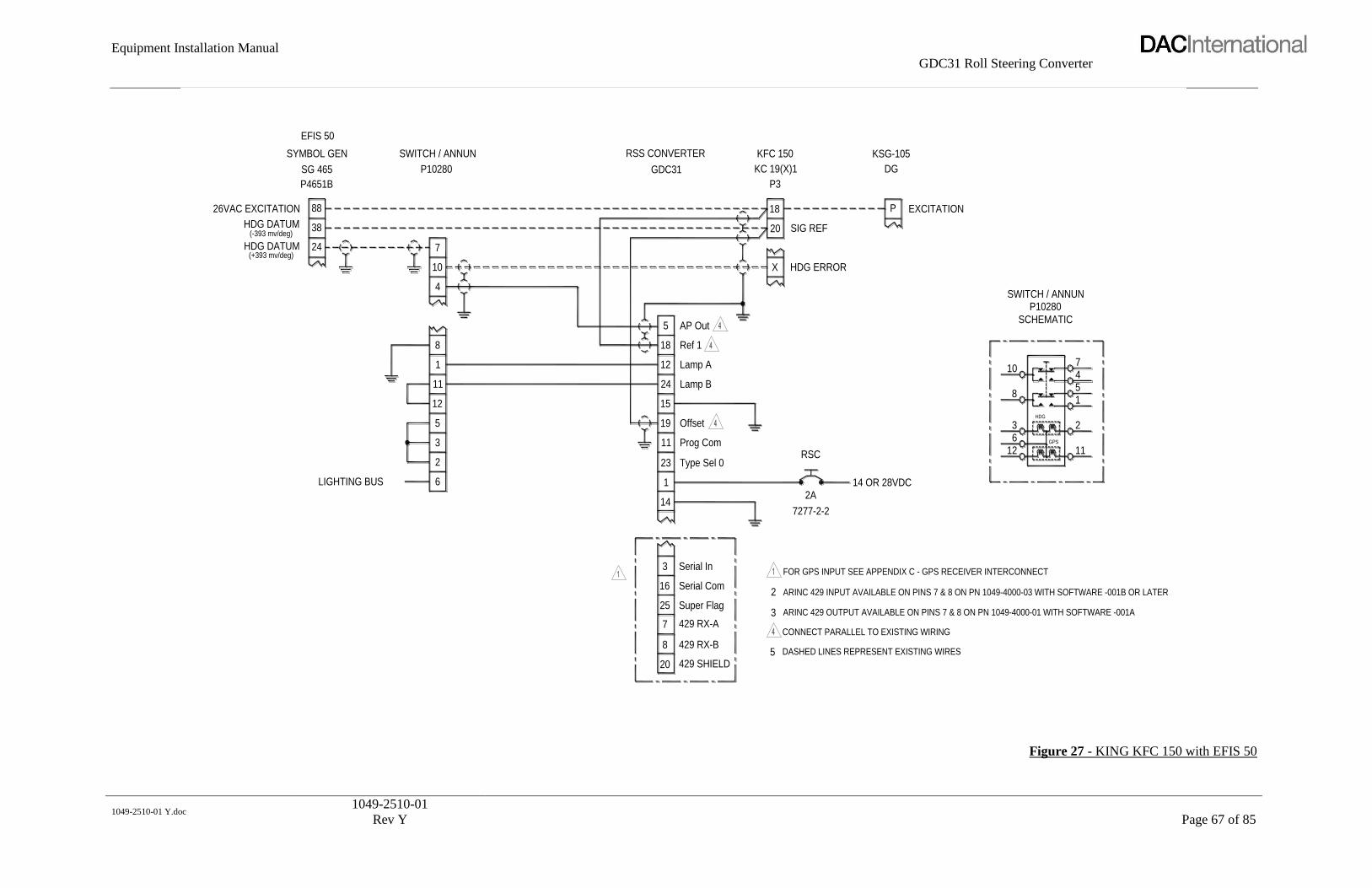
Equipment Installation Manual
GDC31 Roll Steering Converter
1049-2510-01 Y.doc
1049-2510-01
Rev Y
Page 67 of 85
KC 19(X)1
X
18
20
P3
KFC 150
16LIGHTING BUS
7 429 RX-A
429 RX-B
429 SHIELD20
85
Serial Com
Super Flag
Serial In
16
25
3
14
2
3
P10280
SWITCH / ANNUN
P4651B
(+393 mv/deg)
(-393 mv/deg)
26VAC EXCITATION
HDG DATUM
HDG DATUM
12
3
2
5
1
11
8
38
24
88
10
4
7
SYMBOL GEN
EFIS 50
SG 465
Ref 1
Lamp B
Lamp A
Offset
Prog Com
Type Sel 0
15
11
23
19
12
24
18
AP Out5
RSS CONVERTER
GDC31
14 OR 28VDC
ARINC 429 OUTPUT AVAILABLE ON PINS 7 & 8 ON PN 1049-4000-01 WITH SOFTWARE -001A
ARINC 429 INPUT AVAILABLE ON PINS 7 & 8 ON PN 1049-4000-03 WITH SOFTWARE -001B OR LATER
CONNECT PARALLEL TO EXISTING WIRING
DASHED LINES REPRESENT EXISTING WIRES
FOR GPS INPUT SEE APPENDIX C - GPS RECEIVER INTERCONNECT
7277-2-2
2A
EXCITATION
RSC
HDG ERROR
SIG REF
P
612
3
10
8
GPS
HDG
11
2
451
7
SWITCH / ANNUN
SCHEMATIC
P10280
KSG-105
DG
Figure 27 - KING KFC 150 with EFIS 50

Equipment Installation Manual
GDC31 Roll Steering Converter
1049-2510-01 Y.doc
1049-2510-01
Rev Y
Page 68 of 85
SWITCH / ANNUNC
4(600 mv/deg)
3
LIGHTING BUS 6
2
5
12
11
8
1
P10280KI-525A
HDG/CRS REF
HDG ERROR P
S
+15VDC
-15VDC Y
f
P1
10
7
7277-2-2
IF TURNS ARE SLUGGISH, INSTALL THIS JUMPERUSE THIS JUMPER ONLY ON -03 MODEL WITH SOFTWARE -001B OR LATER
FOR GPS INPUT SEE APPENDIX C - GPS RECEIVER INTERCONNECT
ARINC 429 INPUT AVAILABLE ON PINS 7 & 8 ON PN 1049-4000-03 WITH SOFTWARE -001B OR LATER
ARINC 429 OUTPUT AVAILABLE ON PINS 7 & 8 ON PN 1049-4000-01 WITH SOFTWARE -001A
CONNECT PARALLEL TO EXISTING WIRING
DASHED LINES REPRESENT EXISTING WIRING429 SHIELD20
16
7
8
25
3
SERIAL COMMON
SUPER FLAG IN
429 RX-A
429 RX-B
SERIAL IN
6
4
3
14 OR 28VDC
+15 VDC REG
-15 VDC REG
5 AP-OUT
22 GAINSEL0
9
14
1
13
23
19
21
BAUDSEL1
PHASE SELECT
TYPE SELECT
AP-OFFSET
GAINSEL2
10
11
24
6
12
15
PROG PIN COMMON
GPS LAMP B
GAINSEL1
GPS LAMP A
AP-REF2
AP-COM
2A
RSC
CHASSIS GND
SIGNAL GND
A
10
P19(X)1
KC-191 / KC-192 FLIGHTCOMPUTERGDC31
1049-4000-03
RSS CONVERTER
KG-102/KG-102A
DC HDG DATUM (HDG SEL HI)
HDG DATUM REF (LO)
DATUM REF
X
20
19
P19(X)2
K
H
KFC-150
P10280
3 2
12
6 GPS
11
8
104
HDG
1
5
SCHEMATIC
7
SWITCH / ANNUNC
Figure 28 - KING KFC 150 with KI-525A

Equipment Installation Manual
GDC31 Roll Steering Converter
1049-2510-01 Y.doc
1049-2510-01
Rev Y
Page 69 of 85
LIGHTING BUS
DC HDG DATUM
SIGNAL GRND
P2 P2
26 26
4
P1
1
P2
SN 3308 SN 3500
USE THIS JUMPER ONLY ON -03 MODEL WITH SOFTWARE -001B OR LATERIF TURNS ARE SLUGGISH, INSTALL THIS JUMPER
FOR GPS INPUT SEE APPENDIX C - GPS RECEIVER INTERCONNECT
ARINC 429 INPUT AVAILABLE ON PINS 7 & 8 ON PN 1049-4000-03 WITH SOFTWARE -001B OR LATER
ARINC 429 OUTPUT AVAILABLE ON PINS 7 & 8 ON PN 1049-4000-01 WITH SOFTWARE -001A
DASHED LINES REPRESENT EXISTING WIRING
CONNECT PARALLEL TO EXISTING WIRING (EXISTING WIRING NOT ILLUSTRATED FROM DG)
429 SHIELD20
SUPER FLAG IN
PHASE SELECT
TYPE SELECT
16 SERIAL COM
429 RX-A
429 RX-B
7
8
25
SERIAL IN3
6
13
14
1
AP-OFFSET
BAUDSEL1
19
9
23
3
6
4
14 OR 28VDC
RSC 2A
7277-2-2
6
12
3
GPS
HDG
11
2
DIRECTIONAL
PROG PIN COMMON12
3
2
5
1
11
8
11
GAINSEL0
GAINSEL2
GAINSEL1
22
21
10
GPS LAMP A
GPS LAMP B
AP-REF2
12
24
6
10
4
7
AP-OUT
AP-COM
5
15
HDG DATUM HI
HDG DATUM LO
X
20
P10280SWITCH / ANNUNC
GDC31RSS CONVERTER
1049-4000-03
P1901
COMPUTERKC190/KC191/KC192
KFC-150 SERIES
+15 VDC REGH
SWITCH / ANNUNC
SCHEMATIC
8
10
P10280
SIGNAL GNDY
5
1
4
7
GYRO
KG-102A
Figure 29 - KING KFC 150 with SN3308 / SN3500 & KG-102A

Equipment Installation Manual
GDC31 Roll Steering Converter
1049-2510-01 Y.doc
1049-2510-01
Rev Y
Page 70 of 85
LIGHTING BUS
Y-15VDC
HDG/CRS REF
SIGNAL GND
HDG ERROR
(600 mv/deg)
P
j
S
+15VDC
P1
f
KI-525A
23
USE THIS JUMPER ONLY ON -03 MODEL WITH SOFTWARE -001B OR LATER
IF TURNS ARE SLUGGISH, INSTALL THIS JUMPER
FOR GPS INPUT SEE APPENDIX C - GPS RECEIVER INTERCONNECT
ARINC 429 INPUT AVAILABLE ON PINS 7 & 8 ON PN 1049-4000-03 WITH SOFTWARE -001B OR LATER
ARINC 429 OUTPUT AVAILABLE ON PINS 7 & 8 ON PN 1049-4000-01 WITH SOFTWARE -001A
CONNECT PARALLEL TO EXISTING WIRING
DASHED LINES REPRESENT EXISTING WIRING
429 SHIELD20
AP-OFFSET
TYPE SELECT
BAUDSEL1
PHASE SELECT
SERIAL IN
SUPER FLAG IN
429 RX-A
429 RX-B
SERIAL COM16
25
8
7
3
6
13
1
14
23
9
19
3
6
4
2ARSC
7277-2-2
14 OR 28VDC
12
6
11
GPS
HDG/CRS DATUM REF (LO)
DC HDG DATUM (HDG SEL HI)
GPS LAMP A
GPS LAMP B
GAINSEL0
GAINSEL2
GAINSEL1
PROG PIN COMMON12
5
2
3
8
11
1
11
10
21
22
6
24
12
AP-REF2
10
7
4
15
5 AP-OUT
AP-COM
16
17
H
M
SWITCH / ANNUNCP10280
RSS CONVERTERGDC31
1049-4000-03 COMPUTER
KFC-200 / KFC250KFC-275/325
KCP-220P2201
KC-295 / KCP-299P2952 / P2992
K -15 VDC REG
P10280
410
HDG
81
5
SCHEMATIC
7
SIGNAL GNDY
SWITCH / ANNUNC
+15 VDC REG
DIRECTIONAL
H
GYRO
KG-102A
Figure 30 - KING KFC 200 / 300 Series with KI-525A

Equipment Installation Manual
GDC31 Roll Steering Converter
1049-2510-01 Y.doc
1049-2510-01
Rev Y
Page 71 of 85
LIGHTING BUS
GPS
SWITCH / ANNUNC
SCHEMATICP10280
12
3
6
HDG
10
8
26 VAC (C) E
HDG SELECT (X) A
B(Y)
26 VAC (H) D
J5501KPI-550A
6 22 GAINSEL0
GROUND BOTH ENDS OF ALL SHIELDING
DASHED LINES REPRESENT EXISTING WIRING
CONNECT PARALLEL TO EXISTING WIRING
ARINC 429 INPUT AVAILABLE ON PINS 7 & 8 ON PN 1049-4000-03 WITH SOFTWARE -001B OR LATER
ARINC 429 OUTPUT AVAILABLE ON PINS 7 & 8 ON PN 1049-4000-01 WITH SOFTWARE -001A
FOR GPS INPUT SEE APPENDIX C - GPS RECEIVER INTERCONNECT
IF TURNS ARE SLUGGISH, INSTALL THIS JUMPER
USE THIS JUMPER ONLY ON -03 MODEL WITH SOFTWARE -001B OR LATER
11429 SHIELD20
SERIAL COM
SUPER FLAG IN
429 RX-A
429 RX-B
SERIAL IN
BAUDSEL1
AP-OFFSET
TYPE SELECT
1
2
4
5
7
16
7
8
25
3
1
14
19
9
23
3
6
4
2A
7277-2-2
RSC
14 OR 28VDC
26 VAC INV
GAINSEL1
PHASE SELECT
GPS LAMP A
GPS LAMP B
GAINSEL2
PROG PIN COMMON
AP-REF1
8 15
5
2
3
11
12
1
11
10
13
24
12
21
4
10
7
18
5
AP-COM
AP-OUT
2
5
4
6
1
3
6
7
SWITCH / ANNUNCP10280
RSS CONVERTERGDC31
1049-4000-03
ISOLATIONCOUPLER
1049-4801-01
KA-118J1181
5
LO
HI
Figure 31 - KING KFC 200 with KA-118 & KPI-550A

Equipment Installation Manual
GDC31 Roll Steering Converter
1049-2510-01 Y.doc
1049-2510-01
Rev Y
Page 72 of 85
LIGHTING BUS
DC HDG DATUM
HDG/CRS REF
P
P8251
S
KI-825
USE THIS JUMPER ONLY ON -03 MODEL WITH SOFTWARE -001B OR LATERIF TURNS ARE SLUGGISH, INSTALL THIS JUMPER
FOR GPS INPUT SEE APPENDIX C - GPS RECEIVER INTERCONNECT
ARINC 429 INPUT AVAILABLE ON PINS 7 & 8 ON PN 1049-4000-03 WITH SOFTWARE -001B OR LATER
ARINC 429 OUTPUT AVAILABLE ON PINS 7 & 8 ON PN 1049-4000-01 WITH SOFTWARE -001A
DASHED LINES REPRESENT EXISTING WIRING
CONNECT PARALLEL TO EXISTING WIRING (EXISTING WIRING NOT ILLUSTRATED FROM DG)
429 SHIELD20
SUPER FLAG IN
PHASE SELECT
TYPE SELECT
16 SERIAL COM
429 RX-A
429 RX-B
7
8
25
SERIAL IN3
6
13
14
1
AP-OFFSET
BAUDSEL1
19
9
23
3
6
4
14 OR 28VDC
RSC 2A
7277-2-2
6
12
3
GPS
HDG
11
2
DIRECTIONAL
PROG PIN COMMON12
3
2
5
1
11
8
11
GAINSEL0
GAINSEL2
GAINSEL1
22
21
10
GPS LAMP A
GPS LAMP B
AP-REF2
12
24
6
10
4
7
AP-OUT
AP-COM
5
15
HDG DATUM HI
HDG DATUM LO
H
M
P10280SWITCH / ANNUNC
GDC31RSS CONVERTER
1049-4000-03
P2952
COMPUTER
KFC-200 SERIES
+15 VDC REGH
SWITCH / ANNUNC
SCHEMATIC
8
10
P10280
SIGNAL GNDY
5
1
4
7
GYRO
KG-102A
Figure 32 - KING KFC 200 with KI-825 HSI
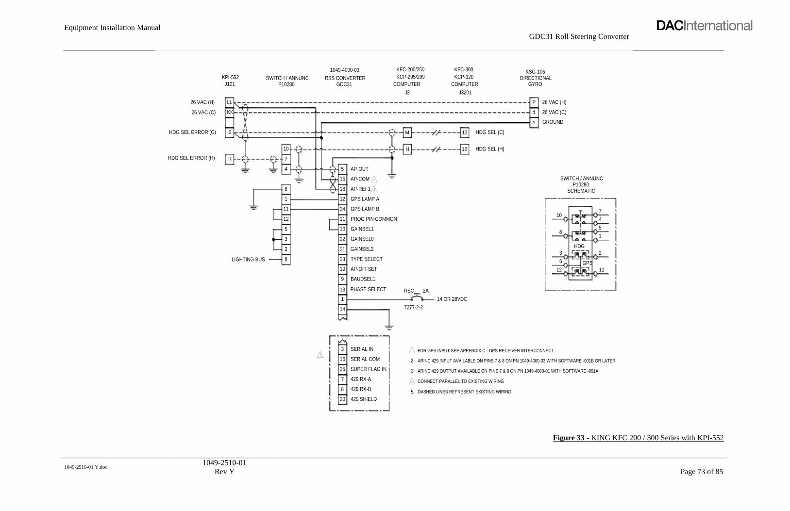
Equipment Installation Manual
GDC31 Roll Steering Converter
1049-2510-01 Y.doc
1049-2510-01
Rev Y
Page 73 of 85
LIGHTING BUS
KK26 VAC (C)
HDG SEL ERROR (C)
HDG SEL ERROR (H) R
S
26 VAC (H)
KPI-552
LL
J101
3 2
FOR GPS INPUT SEE APPENDIX C - GPS RECEIVER INTERCONNECT
ARINC 429 INPUT AVAILABLE ON PINS 7 & 8 ON PN 1049-4000-03 WITH SOFTWARE -001B OR LATER
ARINC 429 OUTPUT AVAILABLE ON PINS 7 & 8 ON PN 1049-4000-01 WITH SOFTWARE -001A
CONNECT PARALLEL TO EXISTING WIRING
DASHED LINES REPRESENT EXISTING WIRING
429 SHIELD20
BAUDSEL1
AP-OFFSET
TYPE SELECT
PHASE SELECT
SERIAL IN
429 RX-B
429 RX-A
SUPER FLAG IN
SERIAL COM16
25
7
8
3
6
13
14
1
23
19
9
2
5
3
2ARSC
7277-2-2
14 OR 28VDC
12
6 GPS
11
HDG SEL (C)
HDG SEL (H)
AP-COM
AP-REF1
GPS LAMP B
GPS LAMP A
GAINSEL1
GAINSEL2
GAINSEL0
PROG PIN COMMON12
3
2
5
11
1
8
11
10
21
22
18
24
12
10
4
7
15
AP-OUT5
H
M
12
13
SWITCH / ANNUNCP10280
RSS CONVERTERGDC31
1049-4000-03
KCP-295/299
COMPUTER
J2
KFC-200/250
KCP-320
COMPUTER
J3201
KFC-300
26 VAC (C)d
SWITCH / ANNUNC
SCHEMATICP10280
8
HDG
10
e GROUND
4
1
5
7
KSG-105
GYRODIRECTIONAL
P 26 VAC (H)
Figure 33 - KING KFC 200 / 300 Series with KPI-552

Equipment Installation Manual
GDC31 Roll Steering Converter
1049-2510-01 Y.doc
1049-2510-01
Rev Y
Page 74 of 85
LIGHTING BUS
P2
26
4
P1
DC HDG DATUM
(600 mv/deg)
HDG/CRS REF
P2
26
1
P2
SN3308 SN3500
CONNECT PARALLEL TO EXISTING WIRING (EXISTING WIRING NOT ILLUSTRATED FROM DG)
DASHED LINES REPRESENT EXISTING WIRING
ARINC 429 OUTPUT AVAILABLE ON PINS 7 & 8 ON PN 1049-4000-01 WITH SOFTWARE -001A
ARINC 429 INPUT AVAILABLE ON PINS 7 & 8 ON PN 1049-4000-03 WITH SOFTWARE -001B OR LATER
FOR GPS INPUT SEE APPENDIX C - GPS RECEIVER INTERCONNECT
USE THIS JUMPER ONLY ON -03 MODEL WITH SOFTWARE -001B OR LATERIF TURNS ARE SLUGGISH, INSTALL THIS JUMPER
429 SHIELD20
SUPER FLAG IN
PHASE SELECT
TYPE SELECT
16 SERIAL COM
429 RX-A
429 RX-B
7
8
25
SERIAL IN3
6
13
14
1
AP-OFFSET
BAUDSEL1
19
9
23
3
6
4
14 OR 28VDC
RSC 2A
7277-2-2
6
12
3
GPS
HDG
11
2
DIRECTIONAL
PROG PIN COMMON12
3
2
5
1
11
8
11
GAINSEL0
GAINSEL2
GAINSEL1
22
21
10
GPS LAMP A
GPS LAMP B
AP-REF2
12
24
6
10
4
7
AP-OUT
AP-COM
5
15
DC HDG DATUM (HDG SEL HI)
HDG/CRS DATUM REF (LO)
H
M
P10280SWITCH / ANNUNC
GDC31RSS CONVERTER
1049-4000-03
COMPUTERKC295
KFC-200 SERIES
+15 VDC REGH
SWITCH / ANNUNC
SCHEMATIC
8
10
P10280
SIGNAL GNDY
5
1
4
7
GYRO
KG-102A
Figure 34 - KING KFC 200 Series with SN3308 / SN3500 & KG-102A
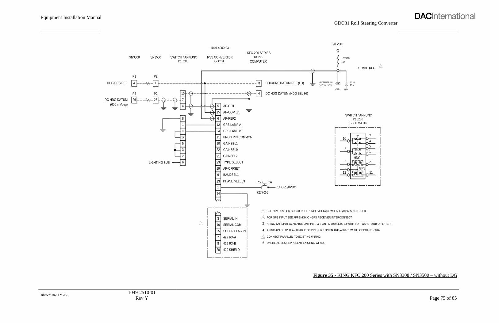
Equipment Installation Manual
GDC31 Roll Steering Converter
1049-2510-01 Y.doc
1049-2510-01
Rev Y
Page 75 of 85
LIGHTING BUS
DC HDG DATUM
(600 mv/deg)
HDG/CRS REF
P2P2
26 26
4
P1
1
P2
SN3308 SN3500
HDG
DASHED LINES REPRESENT EXISTING WIRING
CONNECT PARALLEL TO EXISTING WIRING
ARINC 429 OUTPUT AVAILABLE ON PINS 7 & 8 ON PN 1049-4000-01 WITH SOFTWARE -001A
ARINC 429 INPUT AVAILABLE ON PINS 7 & 8 ON PN 1049-4000-03 WITH SOFTWARE -001B OR LATER
FOR GPS INPUT SEE APPENDIX C - GPS RECEIVER INTERCONNECT
USE 28 V BUS FOR GDC 31 REFERENCE VOLTAGE WHEN KG102A IS NOT USED
429 SHIELD20
TYPE SELECT
AP-OFFSET
BAUDSEL1
SERIAL IN
429 RX-A
429 RX-B
SERIAL COM
SUPER FLAG IN
PHASE SELECT
16
25
8
7
3
6
13
1
14
23
9
19
3
6
4
2ARSC
7277-2-2
14 OR 28VDC
GPS
12
6
3
11
2
DC HDG DATUM (HDG SEL HI)
GPS LAMP B
GPS LAMP A
AP-REF2
GAINSEL0
GAINSEL2
GAINSEL1
PROG PIN COMMON12
5
2
3
8
11
1
11
10
21
22
6
24
12
10
7
4
15
5 AP-OUT
AP-COM
HDG/CRS DATUM REF (LO)
H
M
P10280SWITCH / ANNUNC
1049-4000-03
GDC31RSS CONVERTER
KFC-200 SERIES
COMPUTER
KC295
SWITCH / ANNUNC
710
81
4
5
P10280SCHEMATIC
(14.5 V - 15.5 V)
15 V ZENER 1W 10 UF
25 V
28 VDC
+15 VDC REG
1 W
4700 OHM
Figure 35 - KING KFC 200 Series with SN3308 / SN3500 – without DG

Equipment Installation Manual
GDC31 Roll Steering Converter
1049-2510-01 Y.doc
1049-2510-01
Rev Y
Page 76 of 85
SIG REF
HDG ERROR
LIGHTING BUS 6 1
429 RX-A7
429 SHIELD
429 RX-B
20
85
Serial In
Super Flag
Serial Com16
25
3
14
2
3
SWITCH / ANNUNP10280
HDG DATUM
HDG DATUM
26VAC EXCITATION
(-393 mv/deg)
(+393 mv/deg)
3
2
5
12
11
1
8
38
24
10
4
7
SYMBOL GEN
SG 465
EFIS 50
Prog Com
Type Sel 0
Offset
Lamp A
Lamp B
Ref 1
11
23
19
15
24
12
18
AP Out5
34
35
36
RSS CONVERTERGDC31
KFC 325
KCP 220
P3
14 OR 28VDC
ARINC 429 OUTPUT AVAILABLE ON PINS 7 & 8 ON PN 1049-4000-01 WITH SOFTWARE -001A
ARINC 429 INPUT AVAILABLE ON PINS 7 & 8 ON PN 1049-4000-03 WITH SOFTWARE -001B OR LATER
DASHED LINES REPRESENT EXISTING WIRING
CONNECT PARALLEL TO EXISTING WIRING
FOR GPS INPUT SEE APPENDIX C - GPS RECEIVER INTERCONNECT
7277-2-2
2A
RSC
P EXCITATION
12
36
10
8
HDG
GPS
11
2
451
7
SWITCH / ANNUN
SCHEMATIC
P10280
KSG 105
DG
Figure 36 - KING KFC 325 with EFIS 50

Equipment Installation Manual
GDC31 Roll Steering Converter
1049-2510-01 Y.doc
1049-2510-01
Rev Y
Page 77 of 85
RSS CONVERTER
LIGHTING BUS
6 GPS
1112
47
1
2
5
SWITCH / ANNUN
3
8
10
HDG
P10280SCHEMATIC
6
2
NSD-360ANSD-1000
HEADING ERROR
46
21
EXCITATION GND
+10VDC EXCITATION
19
20
8
12
5
3
11
1
4
10
7
P10280SWITCH / ANNUN
DASHED LINES REPRESENT EXISTING WIRING
ARINC 429 OUTPUT AVAILABLE ON PINS 7 & 8 ON PN 1049-4000-01 WITH SOFTWARE -001A
ARINC 429 INPUT AVAILABLE ON PINS 7 & 8 ON PN 1049-4000-03 WITH SOFTWARE -001B OR LATER
FOR GPS INPUT SEE APPENDIX C - GPS RECEIVER INTERCONNECT
429 RX-B8
429 SHIELD20 5
Super Flag
Serial Com
429 RX-A
Type Sel 0
16
7
25
3 Serial In
14
1
23
3
2
CONNECT PARALLEL TO EXISTING WIRING
14 OR 28VDC2A
7277-2-2
RSC
PROG COMP
S-TEC 50
Prog Com
Offset 19
11
24
12
Lamp B
Lamp A
5
15
6
AP Out
AP Com
Ref 2
GDC31
25
31
27
28
PROG COMP
S-TEC 55
39
4
43
38
HEADING ERROR
SIGNAL REF (+5 vdc)26
19
EXCITATION GND
+10VDC EXCITATION
S-TEC 60/65
34
5
RFGC
Figure 37 - S-TEC 50/55/60/65 (DC) with NSD-360A / NSD-1000
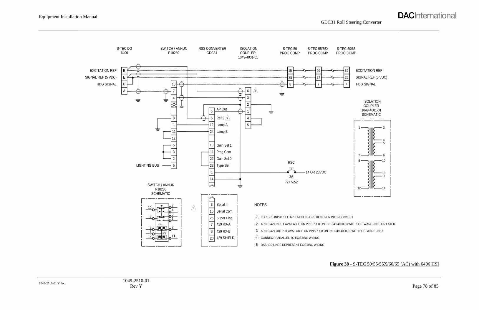
Equipment Installation Manual
GDC31 Roll Steering Converter
1049-2510-01 Y.doc
1049-2510-01
Rev Y
Page 78 of 85
3 ARINC 429 OUTPUT AVAILABLE ON PINS 7 & 8 ON PN 1049-4000-01 WITH SOFTWARE -001A8 429 RX-B23
DASHED LINES REPRESENT EXISTING WIRING
CONNECT PARALLEL TO EXISTING WIRING126
20
GPS
11429 SHIELD
5
ARINC 429 INPUT AVAILABLE ON PINS 7 & 8 ON PN 1049-4000-03 WITH SOFTWARE -001B OR LATER
FOR GPS INPUT SEE APPENDIX C - GPS RECEIVER INTERCONNECT
NOTES:
LIGHTING BUS
P10280SWITCH / ANNUN
SCHEMATIC
8
10
1
16
14
255
HDG
1
47
429 RX-A
Super Flag
7
Serial In
Serial Com
3
2
12
23
22
11
10
24
5
2
6
3
12
11
1
8
Gain Sel 1
Gain Sel 0
Type Sel
Prog Com
Lamp B
Ref 2
Lamp A
6
5
4
HDG SIGNAL
SIGNAL REF (5 VDC)
EXCITATION REF
A
B
E
D
S-TEC DG6406
1049-4801-01
4
7
10
AP Out5 1
2
3
6
RSS CONVERTERGDC31
SWITCH / ANNUNP10280
ISOLATIONCOUPLER
SCHEMATIC
14 OR 28VDC
7277-2-2
2A
12
RSC9
2
1
13
14
11
5
10
6
3
4
COUPLERISOLATION
EXCITATION REF
SIGNAL REF (5 VDC)
HDG SIGNAL
1049-4801-01
26
27
7
25
15
8
36
26
4
S-TEC 55/55XPROG COMP
S-TEC 50PROG COMP
S-TEC 60/65PROG COMP
Figure 38 - S-TEC 50/55/55X/60/65 (AC) with 6406 HSI

Equipment Installation Manual
GDC31 Roll Steering Converter
1049-2510-01 Y.doc
1049-2510-01
Rev Y
Page 79 of 85
LIGHTING BUS
-15VDC Y
SIGNAL GND
HDG ERROR
HDG/CRS REF
P
j
S
+15VDC
P1
f
KI-525A
3 2
FOR GPS INPUT SEE APPENDIX C - GPS RECEIVER INTERCONNECT
ARINC 429 INPUT AVAILABLE ON PINS 7 & 8 ON PN 1049-4000-03 WITH SOFTWARE -001B OR LATER
ARINC 429 OUTPUT AVAILABLE ON PINS 7 & 8 ON PN 1049-4000-01 WITH SOFTWARE -001A
CONNECT PARALLEL TO EXISTING WIRING
DASHED LINES REPRESENT EXISTING WIRING5429 SHIELD20
BAUDSEL1
AP-OFFSET
TYPE SELECT
PHASE SELECT
SERIAL IN
429 RX-B
429 RX-A
SUPER FLAG IN
SERIAL COM16
25
8
7
3
6
13
1
14
23
9
19
2
3
2ARSC
7277-2-2
14 OR 28VDC
1112
6 GPS
RFGC
STEC-60
13
19
GPS LAMP A
GPS LAMP B
GAINSEL1
GAINSEL0
PROG PIN COMMON
GAINSEL212
5
2
3
8
11
1
21
10
11
22
6
24
12
AP-REF2
10
7
4
15
5 AP-OUT
AP-COM
31
29
28
29
P10280SWITCH / ANNUNC
1049-4000-03
GDC31RSS CONVERTER STEC-50
PROG COMP
STEC-55
PROG COMP
K -15 VDC REG
SIGNAL GND
P10280
410
HDG
81
5
SCHEMATIC
7
DC HDG DATUM (HDG SEL HI)
HDG/CRS DATUM REF (LO)
SWITCH / ANNUNC
Y
+15 VDC REG
KG-102ADIRECTIONAL
H
GYRO
Figure 39 - S-TEC 50/55/60 with KI-525A
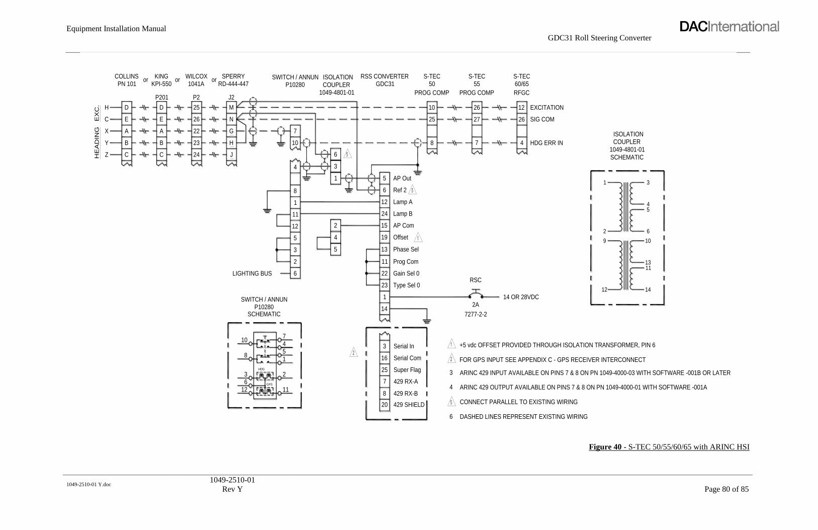
Equipment Installation Manual
GDC31 Roll Steering Converter
1049-2510-01 Y.doc
1049-2510-01
Rev Y
Page 80 of 85
13
3
16
25
7
8
20
1
14
11
22
23
GDC31RSS CONVERTER
19
5
6
12
15
24
85
12
36
HDG
2
GPS
11
1
LIGHTING BUS
10
SWITCH / ANNUN
SCHEMATIC
74
P10280
6
212
3
2
5
5
4
11
8
1
1041AWILCOX
23
24
22
25
26
P2H
EA
DIN
GE
XC
.
Y B
Z C
X
H
C
A
D
E
B
C
A
D
E
orPN 101
COLLINSKPI-550
P201
KINGor
P10280SWITCH / ANNUN
H
J
G
N
M
SPERRYRD-444-447
or
J2
10
4 3
1
6
7
ISOLATIONCOUPLER
1049-4801-01
DASHED LINES REPRESENT EXISTING WIRING
CONNECT PARALLEL TO EXISTING WIRING
FOR GPS INPUT SEE APPENDIX C - GPS RECEIVER INTERCONNECT
+5 vdc OFFSET PROVIDED THROUGH ISOLATION TRANSFORMER, PIN 6
ARINC 429 INPUT AVAILABLE ON PINS 7 & 8 ON PN 1049-4000-03 WITH SOFTWARE -001B OR LATER
ARINC 429 OUTPUT AVAILABLE ON PINS 7 & 8 ON PN 1049-4000-01 WITH SOFTWARE -001A429 RX-B
429 SHIELD
Serial Com
429 RX-A
Super Flag
6
3
4
7277-2-2
RSCGain Sel 0
Serial In
Type Sel 0
2A
AP Com
Phase Sel
Prog Com
Offset
Lamp B
Lamp A
Ref 2
14 OR 28VDC
11
12 14
2
9
6
10
13
54
26
27
55S-TEC
PROG COMP
25
10
8
AP Out
7
PROG COMP
50S-TEC
4
26
12
HDG ERR IN
EXCITATION
SIG COM
RFGC
60/65S-TEC
1049-4801-01COUPLERISOLATION
SCHEMATIC
1 3
Figure 40 - S-TEC 50/55/60/65 with ARINC HSI

Equipment Installation Manual
GDC31 Roll Steering Converter
1049-2510-01 Y.doc
1049-2510-01
Rev Y
Page 81 of 85
20 429 SHIELD6CONNECT COUPLER PINS 1, 2 & 13 PARALLEL TO EXISTING WIRING
GROUND BOTH ENDS OF ALL SHIELDING
DASHED LINES REPRESENT EXISTING WIRING
12GPS
11
6
ARINC 429 INPUT AVAILABLE ON PINS 7 & 8 ON PN 1049-4000-03 WITH SOFTWARE -001B OR LATER
ARINC 429 OUTPUT AVAILABLE ON PINS 7 & 8 ON PN 1049-4000-01 WITH SOFTWARE -001A
FOR GPS INPUT SEE APPENDIX C - GPS RECEIVER INTERCONNECT
SETS SCALING TO APPROXIMATELY .0026 (THIS VALUE IS NOT REFERENCED IN THE GAIN TABLES
THIS GAIN STRAPPING AND CONFIGURATION OF THE ISOLATION COUPLER WIRING EFFECTIVELY
IN THE INSTALLATION SECTION OF THIS MANUAL)
NOTES:
SCHEMATIC
SWITCH / ANNUNP10280
LIGHTING BUS
8
3
10
14
7
1
HDG
2
45
Serial Com16
429 RX-A7
429 RX-B8
Super Flag25
4
3
Serial In3
3
6
2
5
12
11
1
Prog Com11 11
Phase Sel13
1
Gain Sel 022 12
Type Sel
Gain Sel 110
23
Lamp A
Lamp B24
12
14
6
5
4
HEADING ERROR A
E
B
1U262-006-45
8
4
7
10
AP Out
Ref 118
5
3
9
10
13
2
1
GDC31P102801049-4801-01
COUPLER
1 3
2A
7277-2-2 12
14 OR 28VDC
RSC
2
9
14
6
1113
10
54
ROLL EXCITATION 10VAC P-P (3VRMS)
ISOLATION
SCHEMATIC
1049-4801-01COUPLER
8
25
15
SIGNAL REF (5V Offset)
DG HDG SIGNAL4
26
36
S-TEC 60/65RFGCPROG COMP
S-TEC 50
Figure 41 - S-TEC 50/60/65 (AC) with 1U262-006-45 DG

Equipment Installation Manual
GDC31 Roll Steering Converter
1049-2510-01 Y.doc
1049-2510-01
Rev Y
Page 82 of 85
429 SHIELD20ARINC 429 INPUT AVAILABLE ON PINS 7 & 8 ON PN 1049-4000-03 WITH SOFTWARE -001B OR LATER
ARINC 429 OUTPUT AVAILABLE ON PINS 7 & 8 ON PN 1049-4000-01 WITH SOFTWARE -001A
CONNECT PARALLEL TO EXISTING WIRING
DASHED LINES REPRESENT EXISTING WIRING
GROUND BOTH ENDS OF ALL SHIELDING
GPS
126
11
6
4
3
SETS SCALING TO APPROXIMATELY .0026 (THIS VALUE IS NOT REFERENCED IN THE GAIN TABLES
THIS GAIN STRAPPING AND CONFIGURATION OF THE ISOLATION COUPLER WIRING EFFECTIVELY
IN THE INSTALLATION SECTION OF THIS MANUAL)
NOTES:
FOR GPS INPUT SEE APPENDIX C - GPS RECEIVER INTERCONNECT
8 18 3
P10280SWITCH / ANNUN
SCHEMATIC
8
3HDG
10
LIGHTING BUS
429 RX-A
Super Flag
429 RX-B
Serial Com
Serial In
5
2
1
47
7
8
25
16
3
14
Phase Sel
Prog Com
Gain Sel 0
Gain Sel 1
Type Sel
Lamp B
Lamp A
5 10
6
3
2
1
13
11
22
11
12
1
24
23
12
14
11
12
5
6
4
SWITCH / ANNUN
52D54
ROLL EXCITATION
SIGNAL REF
HEADING ERROR
ROLL COMMON
A
B
E
D
1049-4801-01
Ref 1
AP Out
7
4
5
10
10
9
13
2
1
RSS CONVERTERP10280 GDC31
ISOLATIONCOUPLER
2A
7277-2-2 12
RSC
14 OR 28VDC
9
2
1
14
1311
10
6
45
3
ROLL EXCITATION 10VAC P-P (3VRMS)
PROG COMP RFGC
SIGNAL REF (5V Offset)
HDG SIGNAL
25
8
15
26
4
36
1049-4801-01
SCHEMATIC
ISOLATIONCOUPLER
S-TEC 60/65S-TEC 50
Figure 42 - S-TEC 50/60/65 (AC) with 52D54 DG

Equipment Installation Manual
GDC31 Roll Steering Converter
1049-2510-01 Y.doc
1049-2510-01
Rev Y
Page 83 of 85
5
3
2
S-TEC 55PROG COMP
1
429 RX-A7
429 SHIELD
429 RX-B8
20
Serial Com
Super Flag
Serial In
25
3
16
14
SWITCH / ANNUN
EXCITATION D
ROLL COMMON
HDG ERROR
SIG REF
LIGHTING BUS
5
2
6
3
11
12
1
A
B
E
8
4
7
10
DG52D54
P10280
38
Gain Sel 1
Type Sel 0
Prog Com
Lamp A
Lamp B
19 Offset
10
23
11
15
24
12
43
AP Out
18
5
Ref 1
28
27
RSS CONVERTERGDC31
14 OR 28VDC
ARINC 429 OUTPUT AVAILABLE ON PINS 7 & 8 ON PN 1049-4000-01 WITH SOFTWARE -001A
ARINC 429 INPUT AVAILABLE ON PINS 7 & 8 ON PN 1049-4000-03 WITH SOFTWARE -001B OR LATER
CONNECT PARALLEL TO EXISTING WIRING
DASHED LINES REPRESENT EXISTING WIRING
FOR GPS INPUT SEE APPENDIX C - GPS RECEIVER INTERCONNECT
7277-2-2
2A
+10 VDC EXCITATION
RSC
GROUND
SIGNAL REF (+5 VDC)
HDG ERROR
SCHEMATIC
GPS
36
12
8
HDG
10
5
2
11
1
74
P10280SWITCH / ANNUN
Figure 43 - S-TEC 55 (DC) with 52D54DG

Equipment Installation Manual
GDC31 Roll Steering Converter
1049-2510-01 Y.doc
1049-2510-01
Rev Y
Page 84 of 85
3 ARINC 429 OUTPUT AVAILABLE ON PINS 7 & 8 ON PN 1049-4000-01 WITH SOFTWARE -001A6 429 RX-B8
GROUND BOTH ENDS OF ALL SHIELDING
DASHED LINES REPRESENT EXISTING WIRING
CONNECT PARALLEL TO EXISTING WIRING12
20
GPS
11429 SHIELD
5
ARINC 429 INPUT AVAILABLE ON PINS 7 & 8 ON PN 1049-4000-03 WITH SOFTWARE -001B OR LATER
NOTES:
FOR GPS INPUT SEE APPENDIX C - GPS RECEIVER INTERCONNECT
68 9
LIGHTING BUS
SCHEMATIC
SWITCH / ANNUNP10280
8
3
10
14
16
251
HDG
2
45
7 Serial In3
Super Flag
429 RX-A7
Serial Com
2
12
24
22
11
23
105
6
3
2
11
12
1
Gain Sel 1 14
Type Sel
1
Prog Com
Gain Sel 0
13
10
11
Lamp B
Lamp A
5
12
4
6443
HDG SIGNAL
EXCITATION
SIGNAL REF 14
13
1
HSI
1049-4801-01
15
7
4
10
6
Ref 2
AP Out5
AP Com2
1
3
RSS CONVERTERGDC31
SWITCH / ANNUNP10280
ISOLATIONCOUPLER
1 3
2A
7277-2-2
12
14 OR 28VDC
RSC
9
2
14
1311
10
5
6
4
1049-4801-01COUPLER
SCHEMATIC
ISOLATION
4
26
1225
27
7
SIGNAL REF
HDG SIGNAL
EXCITATION
S-TEC 65RFGC
S-TEC 55PROG COMP
Figure 44 - S-TEC 55/65 (AC) with 6443 HSI
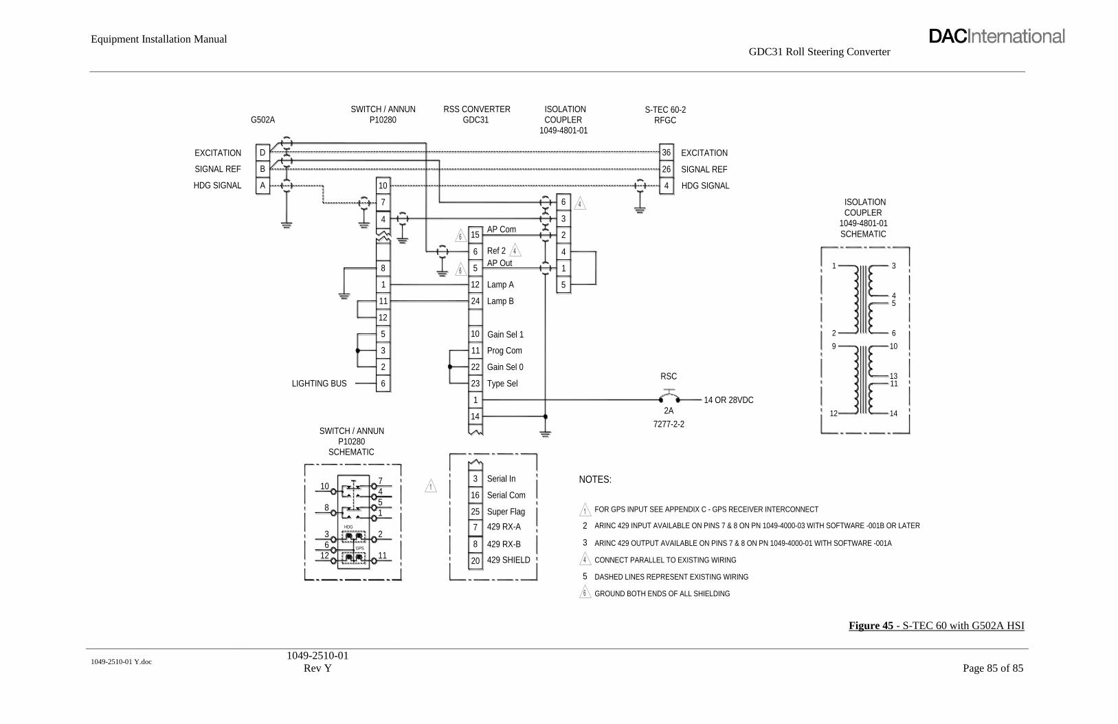
Equipment Installation Manual
GDC31 Roll Steering Converter
1049-2510-01 Y.doc
1049-2510-01
Rev Y
Page 85 of 85
ARINC 429 OUTPUT AVAILABLE ON PINS 7 & 8 ON PN 1049-4000-01 WITH SOFTWARE -001A36 429 RX-B8
GROUND BOTH ENDS OF ALL SHIELDING
DASHED LINES REPRESENT EXISTING WIRING
CONNECT PARALLEL TO EXISTING WIRING12
20
GPS
11429 SHIELD
5
ARINC 429 INPUT AVAILABLE ON PINS 7 & 8 ON PN 1049-4000-03 WITH SOFTWARE -001B OR LATER
NOTES:
FOR GPS INPUT SEE APPENDIX C - GPS RECEIVER INTERCONNECT
5 18
LIGHTING BUS
SCHEMATIC
SWITCH / ANNUNP10280
8
3
10
14
16
251
HDG
2
45
7 Serial In3
Super Flag
429 RX-A7
Serial Com
2
12
24
22
11
23
105
6
3
2
11
12
1
Gain Sel 1
Type Sel
1
Prog Com
Gain Sel 0
Lamp B
Lamp A 5
HDG SIGNAL
EXCITATION
SIGNAL REF B
A
D
G502A1049-4801-01
15
7
4
10
6
Ref 2
AP Out
6
AP Com2
4
3
RSS CONVERTERGDC31
SWITCH / ANNUNP10280
ISOLATIONCOUPLER
1 3
2A
7277-2-2
12
14 OR 28VDC
RSC
9
2
14
1311
10
5
6
4
1049-4801-01COUPLER
SCHEMATIC
ISOLATION
36
26
4
SIGNAL REF
HDG SIGNAL
EXCITATION
S-TEC 60-2RFGC
Figure 45 - S-TEC 60 with G502A HSI