equipment research centre scott i sh school s science
TRANSCRIPT

SCOTT I SH SCHOOL S SCIENCE
EQUIPMENT RESEARCH CENTRE
Bulletin No. 141 June 1984

ADDRESS LIST
SSSERC, 103, Broughton Street, Edinburgh EH1 3R7Tel.031—556 2184 or 031—557 1037.
3. Auld Esq.,ASE, Hon. Secretary, Scottish Region, College ofEducation,Gardyne Road, Broughty Ferry, Dundee DD5 INY
British Association for the Advancement of Science, Fortress House,23, Savile Row, London W1X lAB
British Drug Houses (BDH), Broom Road, Poole BH12 4NN Tel.(0202)745520.
Brown F. & Co., 44, George IV Bridge, Edinburgh 1. Tel 031—225 3461.
Griffin & George Ltd.,Ealing Road, Alperton, Wembley, Middlesex HAD1HJ Tel.041—248 5680.
Philip Harris Ltd., 34—36, Strathmore House, Town Centre, EastKilbride 075 1LQ Tel. (03552) 34983 or 34984.
Information Officer, MEDC, Paisley College, High Street, Paisley PAl2BE Tel.041—887 2158 or 041—887 0962.
RS Components, P.O. Box 99, Corby Northants. NN17 9RS [New address forScottish orders] Tel.(0536) 201201.
Scottish Curriculum Development Service, Dundee Centre, College ofEducation, Gardyne Road, Broughty Ferry, Dundee DD5 1NYTel. (0382) 455053.
Linilab Ltd.,Clarendon Road, Blackburn, Lancs. BB1 9TA Tel.(0254) 57643or 57644.
C. SSSERC 1984(Copyright is held to waived only for bona—fide educational useswithin Scottish schools and colleges in current membership of SSSERC).
Typeset by SSSERC in Juki Courier 10 pitch and Triumph AdlerMini—cubic 15 pitch on BBC model B & Beebug Wordwise.
* * * * * *

INTRODUCTION
Normal Service — ASAP
We like to avoid making excuses in these pages.However for those customers who may have noticedsome delay in our response to enquiries and thesomewhat tardy appearance of this Bulletin issue,we would like to state reasons.
The business of SSSERC is information. Likeeveryone else in the information game, we have hadto deal with new technology in our office practiceand publishing activities. This lead to a need torefurbish and rewire our office. Unfortunately inkicking sleeping dogs there is always the dangerof being bitten! The rewiring work resulted in thediscovery of our nth outbreak of dry—rot.
Add to that our being without our only secretaryfor a month, family illnesses, bereavement leaveand a full exhibition/workshop programme and youwill see that these days working at SSSERC isalmost as bad as teaching in a school ! Hopefullythe dust,literally, should have settled by thestart of next session. We can then resume what wehope is seen as our normal high standard ofservice.
Research Fellow
Scottish readers may recall invitations forapplications for this fellowship in a Bulletininsert a couple of issues back. Such mattersalways seem to take an inordinate time to bring toa conclusion. However, we can now announce theappointment, on secondment, of Mr Ian Downie as aSSSERC Research Fellow. Mr Downie is presentlyPrincipal Teacher of Physics at Auchmuty HighSchool in Fife and has acted as a part—timeconsultant to SSSERC since the beginning of April,1984. He will join the staff of this Centre inAugust to begin a full—time two year secondment.
He will be researching and writing a series oftechnical monographs for schools, on generaltechniques in microelectronics and in interfacingdevices to microcomputers and microprocessors.
The project is industry/education grant—aidedthrough the Industry Department Scotland, BritishPetroleum PLC and Britoil. In—kind support has
been committed by a number of commercial andindustrial concerns. The project publications willbe distributed through SCDS Dundee Centre.
Scottish Yoiaig Scientists of the Year
This competition, sponsored jointly by Marconiin Scotland, the Scottish Region ASE and theBritish Association for the Advancement of Science(Tayside and Fife Section), is open to all pupilsin the secondary sector in Scotland. It will runfor the first time in session 1984—85. Details ofthe competition were sent to every Secondary HeadTeacher sometime in April. Have you seen yourschool’s copy? If for some reason it went astray,further copies are available from the ASE RegionSecretary (see Address List, inside front cover).
fDC Courses
We have recently received details of the latestMicroelectronics Educational Development Centrecourse programme, September to December 1984. Anumber of the short courses offered therein may beof interest to teachers and technicians. For thelatter the courses on microprocessor servicing maybe of particular interest.
MEDC courses have a reputation as good value.Realistic course fees are charged and these canbe anything from £60 for a one day seminar to £210for a four day course. Compared with fees formachine specific courses as charged by somecommercial firms these charges look veryreasonable. On any one course a number of freeplaces are reserved for academic staff from thepost secondary sector. For further details of thiscourse programme and other aspects of MEDCactivity, contact the MEDC Information Officer(see Address List).
Saturday opening
As usual we will be suspending Saturday morningopening during the school summer break. The lastSaturday openings in the 1983—84 session were on2nd and 9th of June. Saturday opening will restarton the 1st September,1984 and then on each of the
1

first two Saturdays of each month until further
notice. Normal weekday hours, 9am—5pm, Monday to
Friday will still operate over the summer.
Because staff hope to take leave on rota, you
are advised to telephone in advance if you wish to
see a specific person for specialist advice.
Cost index
Our cost index marks its tenth anniversary
somewhat remarkably. For the first time, it went
down! Between November,19B3 and May,1984 the index
actually fell by 13.8%, from 318.6 to 274.7. The
annual figure from May 1983 becomes —13%.
Obviously, all of the downward movement has been
in the last six months since November ‘83.
Administrators and others would be ill—advised
to take up this -.13% cudgel against science
departments. This first or one—off, decrease
should be viewed against the ten year trend shown
in the histogram. The decrease is a help
certainly, but the index has a lot further to go
down to restore lost purchasing power in many
science departments. In addition we repeat our
recent warning that the index only directly
applies to consumables, our shopping basket
contains no capital items.
Errata Bulletin 140
We apologise for the errors in Bulletin 140
whereby pieces of text from “In the Workshop”
appeared in the midst of “Fibre Optics” in
“Physics Notes”. We were just testing you. More
seriously, this was a printer error at the paste
up stage and outwith our control. Sorry! We are
now doing our own typesetting. In future any such
errors will be all our own work.
* * * * *
We did not have to look far for an explanation.
In costing the shopping basket of consumables, we
obtain prices for equivalent items from more than
one supplier. The prices included in calculating
the index are the lowest quoted. As announced in
Bulletin 139, competition for consumables business
has become very fierce of late. One major supply
house recently introduced major price cuts.
Consequently many of their items leapt into our
basket dragging the index downward.
300
200
100
8r-- LI --f’O
OD1 -O.nthu, rr-, ii, t— a’ D s—m m m ‘
-:t•Lfl ‘0 L-0% m
2
CLEAPSE Guides
We have recently received the following new or
revised guides from our sister organisatiori,
CLEAPSE School Science Service. Copies of these
publications can be borrowed for up to one month
by application to the Director of SSSERC.
L94 “Conductivity Meters.” Hints on the use and
maintenance of meters and probes with a summary
of those available commercially.
Ll35 “Eye Protection.” Part A discusses the
problems and gives advice on the types to
choose; it also includes sections on maintenance
and storage.Part B gives information on current
models.
L153B “Interfacing: Commercial Products.” The
second part of Ll53 “Interfacing Laboratory
Experiments to Computers”.
Ll58 “Laboratory Timing Devices” — mainly
stopclocks and stopwatches with some information
on wallclocks together with brief mention of the
use of computer timer modules as well as CiPSI
and VELA.
MEA “Measuring Cylinder repair.”
MET “Meters”— zero adjusters,hairsprings,shunts
etc., with a note on diode protection.
* * * * *
Seeing the liclt —a shattering experience
We recently received a copy of a Fife circular
to Senior Technicians reporting an accident
involving a l2V auto bulb. The bulb shattered at
switch on. Luckily the flying glass did not cause
any damge but this was a potentially serious
a batch purchased
Marked as made in
by Ring Automotive,
“Tests on the apparatus used point to the
autobulb as being faulty and unsafe for use.” Fife
has instructed any of their schools holding stocks
of these bulbs to withdraw them from use.
‘Verb sap’!
WNetworkingN — an I’ICC Project Report
* *
Most Scottish schools will have by now received
a copy of this report on an investigation into the
simultaneous use of a number of computer systems
in the science classroom. The work reported on was
carried out by Eric Pine of Kyle Academy, Ayr.
SSSERC’s involvement was in the broad supervision
of the project, with Eric theoretically seconded
to this Centre for three days a week. In fact he
did the work in his own school and in the end was
providing technical assistance to us, rather than
the other way around as originally envisaged.
The parent MCC project as a whole is now
formally at an end. Since Eric’s report went to
press he has developed materials which will allow
inexpensive networking of ZXB1 satellites with
machines other than the Apple in the control role.
We have to hand sets of notes detailing hardware
and software requirements for:
—Sinclair Spectrum with microdrive in the
control role with ZX81 satellites. Networking
is carried out through the Griffin ‘I—Pack’
- ports.
—BBC Model B with disc drive in the control
role, ZXB1 satellites. Hardware connection is
via the Beeb user port.
Unfortunately lack of space, and the necessary
context of the basic background in the original
report, preclude direct - publication in the
Bulletin.
However we will make these notes available as an
unofficial annexe to the MCC report. Terms will be
a postal order or cheque for 5Op to cover
photocopying, payable to “SSSERC” please, and a
stamped addressed 23 x 10cm. envelope.
* In co—operation with Mr Munro, Kyle Academy.
* * *
INTERFACING NOTES
SAFETY NOTES
incident.The bulb was part offrom an ASDA supermarket.Romania they were distributed
Leeds and rated 12V, 5W.
3

Sassenach and overseas readers interested inobtaining copies of the main report and details of
other MCC publications should contact theScotti8h Curriculi.n Develop.ent Service
Dundee Centre.[See Address List, inside cover]
The “Networkingt’ report costs £l—50 includingpostage and packing. Orders totalling less than£10 must be accompanied by a Sterling cheque orpostal order, crossed and payable to DundeeCollege of Education.
* * * *
SCIENCE AND THEHANDICAPPED PUPIL
This is a subject in which SSSERC has long hadan interest. Readers may recall Cohn Weatherley’ssterling work at the Royal Blind School. This wasinitially part—time while he was AssistantDirector at SSSERC and then as a full—timeResearch Fellow. There always has been a need fortechnical assistance in these areas. There is nowa renewed urgency and interest.
There are possibly two main reasons for thisrevival. Firstly there has been a developingpolicy of integrating pupils with special needsinto ordinary neighbourhood schools. This iscoupled with a very proper concern that suchpupils share as fully as possible in all of thecurricular elements on offer in the school. Onesuch, major, element is Science. Even whereintegration is not yet the policy, there is anincreased awareness of the need for pupils in‘special’ schools to have some kind of sciencecourse.
Secondly, developments in technology offerrenewed hope of solving problems which a few yearsago lead only to admissions of defeat on groundsof complexity, costs or both. Some of theseproblems may require relatively ‘high—tech’, iffairly cheap, answers. Other difficulties are moreprosaic, requiring for their solution someexperience of the problems of handicap and perhapsa deal of lateral thinking.
For example, the talking balance exists. The
talking thermometer is equally feasible at an
acceptable price,and someone reading this may
already have made one. At the other end of the
scale (sorry!) — how does one solve some of the
problems of the pupil in a wheelchair who cannot
work at a science bench designed for the able
bodied? Again, we know of some sources of ideas,
but possibly someone out there has even better
solutions.
Sadly, multiple handicap seems increasingly
common. It is thus not simply a question of
thinking of the needs of blind pupils or of those
with motor difficulties or mental handicap. Some* problems may be common to several groups. For
example holding equipment steady in an experiment
is a difficulty shared by both the visually
handicapped and those with motor difficulties.
However many groups of handicapped pupils have
their own speciahised needs.
Unfortunately a very full work programme at this
Centre precludes any major primary development
effort, from SSSERC staff, in the short term.
However the Centre always has acted as a clearing
house for ideas and information. We are keen to do
all we can in this way for ideas and designs for
aids to the learning of science by handicapped
pupils. We would welcome correspondence on this
subject and even short articles for circulation or
publication.
Through our Planning Committee we already have
some suggestions from Muriel Buchanan at Firrhill
High, Edinburgh. Firrhill has a twinning
arrangement with the Royal Blind School, teaching
science on an integrated basis visually
handicapped and sighted pupils being taught
together. Muriel points out that even now very
little equipment exists, at an acceptable cost,
that allows blind pupils to do science independent
of assistance from a sighted pupil.
Some of the problems seem ideal for solution by
(micro—)electronic means. Microelectronics is
often described as “solutions looking for
problems”. So, sixth year, and other, projecteers
on the annual project trek, how about tackling one
of the topics listed under “Project Suggestions”
in this issue? The tasks are challenging and the
possible end products socially relevant and very
worthwhile.
* ** * *
4

PROJECTSUGGESTIONS
At this time of year potential CSYS studentsbegin looking for ideas for projects. Finding outabout what has already been done is,theoretically, relatively easy. Cood ideas forfresher ground to break seem harder to locate. Wehave lost count of the biology and chemistrypupils wishing to borrow our oxygen meters forstream surveys. The physics and engineeringproject highways must by now be strewn with theskeletons of dead traffic light systems!
Instrumentation problems and other practicalissues may provide routes to successful projects.The SEB rules, quite properly, guard againstdevelopment of instrumentation becoming an end initself. If such design and development isaccompanied by calibration, data collection andinterpretation a great deal of science may belearned.
4. Colour discrimination
This would open up a great deal of chemistryto the visually handicapped. Translation ofwavelength of light to audio frequency or,moreambitiously, speech output.
5. Science in a eelchair
Mechanical aids —a fertile field involving thephysics of movement, engineering design andapplied human biology (ergonomics andanthropometry).
*
EGG RACESWe are not aiming here to provide complete
project briefs nor hard technical descriptions.Rather we give a series of one— or two—liners, asort of scientific and technical “Why don’t you?”.We start with basic needs for science teachingaids for handicapped pupils (see page 4.).
1. Temperature measurement
a) A very large digital readout thermometerfor the visually impaired, within a tightaccuracy and cost specification.
b) A talking thermometer using a speechsynthesis chip.
2.Neasuring liquid volumes
a) For the visually handicapped, perhaps usingopto—electroriics, with or without raisedexternal markings on the measuring vessel.
b) For the visually handicapped and/or thosewith motor difficulties, novel mechanicalmethods for safely dispensing and measuringliquids.
Continuing on the same arterial, we would drawyour attention to a recent publication from theBritish Association for the Advancement of Scienceand the British Association Young Scientists(BAYS).
Entitled “Ideas for Egg Races and otherproblem—solving activities.”, this is a veryimpressive source book. It contains no less than71 fully specified practical problems suitable foruse by organisers of problem solving activities orcompetitions. Problems are described for a widerange of pupil ages from early primary rightthrough to college students.
Available from the British Association (seeaddress list, front inside cover) price £2—50 plus75p for postage & packing,it must be an essentialweapon in the armoury of anyone interested inpromoting open ended learning.
We were delighted to note that the message evenseems to be getting through to what many see assome of our more conservative (note the little‘c’) institutions. “Ideas for Egg Races” has beenpublished with the support of Lloyds Bank.
3.Electrical measurements
A talking multimeter or, less ambitious, atalking ammeter or voltmeter.
* * * *
* * * * *
5
Solar power
C
(cad resistance (fl.)
400 50
There is a requirement in both of the REFER
“Energy” core topic examplars for simple
demonstrations of’ motors driven by solar cells. In
our exhibitions we had been using a d—i—y mounted
cell from RS and a solar motor sold as a spare by
lrwin—Desman.(Type No. RB0272 at £ll—45). It is
the relatively high price of suitable low current,
low friction motors which has been the main reason
for restricting these activities to demonstration.
Following a suggestion from Liberton High (who
else?) we have been looking at one or two other
cells and motors.
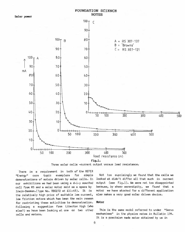
Not too suprisingly we found that the cells welooked at didn’t differ all that much in currentoutput (see Fig.l). We were not too disappointed
because, by sheer serendipity, we found that amotor we have stocked for a different application
also makes a very good solar driven device.
Motor
This is the same model referred to under “Servomechanisms” in the physics notes in Bulletin 139.It is a precision made motor obtained by us in
FOUNDATION SCIENCENOTES
100
90
B 80
90
A
70
I 70
60
100
90
80
70
40
30
20
A RS 307-137B = ‘Browns’C = RS 307-121
2ô0 3Ô0
60
50
40
30
30
20
10
50 100
400 500
00 são
Fig.l.
Three solar cells —current output versus load resistance.
6
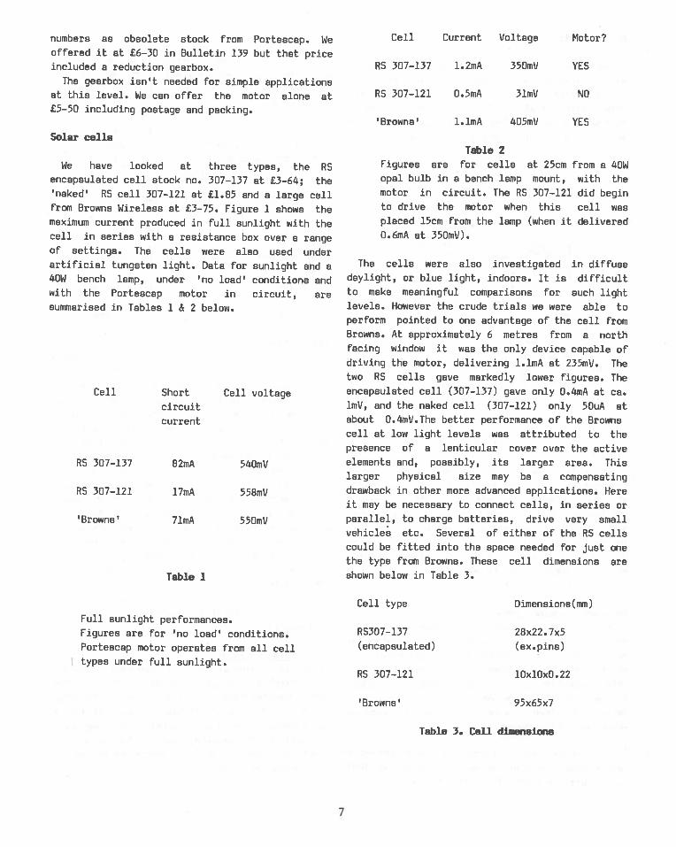
Cell Current Voltage Motor?numbers as obsolete stock from Portescap. Weoffered it at £6—30 in Bulletin 139 but that priceincluded a reduction gearbox.
The gearbox isn’t needed for simple applicationsat this level. We can offer the motor alone at£5—50 including postage and packing.
Solar cellsTable 2
We have looked at three types, the RSencapsulated cell stock no. 307—137 at £3—64; the‘naked’ RS cell 307—121 at £1.85 and a large cellfrom Browns Wireless at £3—75. Figure 1 shows themaximum current produced in full sunlight with thecell in series with a resistance box over a rangeof settings. The cells were also used underartificial tungsten light. Data for sunlight and a40W bench lamp, under ‘no load’ conditions andwith the Portescap motor in circuit, aresummarised in Tables 1 & 2 below.
Short Cell voltagecircuit
current
RS 307—137 82mA 540mV
RS 307—121 l7mA 55BmV
‘Browns’ 7lmA 550mV
Figures are for cells at 25cm from a 40Wopal bulb in a bench lamp mount, with themotor in circuit. The RS 307—121 did beginto drive the motor when this cell wasplaced 15cm from the lamp (when it delivered0.6mA at 350mV).
The cells were also investigated in diffusedaylight, or blue light, indoors. It is difficultto make meaningful comparisons for such lightlevels. However the crude trials we were able toperform pointed to one advantage of the cell fromBrowns. At approximately 6 metres from a northfacing window it was the only device capable ofdriving the motor, delivering l.lmA at 235mV. Thetwo RS cells gave markedly lower figures. Theencapsulated cell (307—137) gave only 0.4mA at ca.lmV, and the naked cell (307—121) only 5OuA atabout 0.4mV.The better performance of the Brownscell at low light levels was attributed to thepresence of a lenticular cover over the activeelements and, possibly, its larger area. Thislarger physical size may be a compensatingdrawback in other more advanced applications. Hereit may be necessary to connect cells, in series orparallel, to charge batteries, drive very smallvehicles etc. Several of either of the RS cellscould be fitted into the space needed for just onethe type from Browns. These cell dimensions areshown below in Table 3.
Full sunlight performances.Figures are for ‘no load’ conditions.Portescap motor operates from all celltypes under full sunlight.
Cell type
RS307—l37
(encapsulated)
RS 307—121
‘Browns’
Dimensions(mm)
28x22. 7x5(ex.pins)
lOxlOxO.22
95x65x7
Table 3. Cell di.ensions
RS 307—137 l.2mA 350mV YES
RS 307—121 0.5mA 3lmV
‘Browns’ 1.lmA 405mV
NO
YES
Cell
Table 1
7

D-i—y soirts
The smaller cells are best used on some kind of
mount provided with standard 4mm terminals.
Suitable mounts for both cell and motor are easily
made frnm that SSSERC favourite — plastic
rainwater pipe. Sketches of such mounts made from
sections of such pipe are shown in figure 2.
lightperspex disc
Fig.2
Hopefully, we have given some usefulinformation, assisting application of these cells
at this level. As with the other “Energy”sub—topics, there is ample scope for extendingsuch work at this and other school levels. Suchfurther use of solar cells is a topic to which wehope to return either in the Bulletin or possiblyanother, separate, SSSERC publication.
* * *
Toothpaste recipe hints
In the Tayside exemplar “HealthyBodies”,Workcard 4 deals with pupil preparation of
small samples of toothpaste. Unfortunately, as
printed, the recipe produces a very stiff mix
unless additional water or glycerine are added.
The need for clarification of this and other smalldetails, has lead to a request for us to publishadditional information.
The “dental soap” referred to is purchased as
sodium lauryl sulphate or sodium dodecyl sulphate
(e.g. Harris 578960/9,53—11 for 250g).
The “gum” is gum tragacanth (Harris 542645/B,£6—96 for lOOg). Two alternative recipes to thesomewhat skeletal version in the REFER examplarrare given below:
precipited calcium carbonatedental soap (sodium lauryl
sulphate)
The first of these recipes comes from “TheScience Master’s Book — Chemistry” (ASE) and isthe same as that in Griffin’s excellent littlebooklet on Cosmetic Science. Neither versionsexplain the nature of “%“, but we think itreasonable to assume that this is by weight. Thisrecipe produces a reasonable paste, but we find thesecond to be better (there we go again, soundinglike an advertising agency!). This second recipeis from “Practical Cosmetic Science” by Ann youngand published by Mills and Boon (no kidding!).This recipe was sent to us by Dreena Campbell ofCraigie High School, Dundee together with othersnippets which may be of interest, and which wesummarise below.
Toothpaste contains several types ofingredients:
(a) Polishing agentThis is obviously one of the most importantingredients. It helps remove particles of foodand discoloration. Materials chosen for thisrole include — precipitated chalk; tricalciumphosphate; aluminium sulphate and magnesium
trisilicate.Approximately half of the weight ofmost toothpastes will be accounted for by thepolishing agent(s).
solar cell
(i) (ii)45% 57g
4% lg
motor
distilled water 28% l9.5g
glycerine 20% 21g
gum tragacanth 1% l.5q
flavouring 1% 1 drop
saccharine / 1 drop
preservative / 1
microspatula
full
8

3. Addition of water and preservative.*(b) Moistener or humectant
This prevents drying out and hardening of thepaste. Suitable agents are — glycerine; sorbitoland propylene glycol. Glycerine is one of’ the moresuitable agents in this present exercise.
Cc) Detergent and foaming agent (dental soap or
cream)A small quantity, 1.5 to 6%, aids the polishingaction by acting as a wetting agent on the teeth.The most popular agents for this role are sodiumor magnesium lauryl sulphates.
(d) Binding agentNatural gums Coops!) such as gum tragacanth areoften used or other natural agents such as starchor sodium alginate. This last is available from,for example, BDH, or their many agents, BDHCat.No. 30105 at £2—70 for 100g. Also used iscarageen or Irish moss extract, often to beobtained from health food outlets. Synthetics suchas polypropylene glycols are also employed.
(e ) Sweetners
Ingredients such as saccharine at 0.1 to 1.3% maybe used. These are preferred to natural sugarswhich tend to crystallise and spoil the smoothpaste.
Cf ) FlavouringOil of peppermint is one of the commonest used butthe field is wide open for experimentation. It isprobably only a matter of time before smoky bacontoothpaste appears on the market.
Cg)PreservativeThe most commonly used are sodium hydroxy—benzoate and sodium benzoate.
All preparations, despite minor differences inrecipes, tend to follow the same sequence:
1. Dispersion of the binding agents in thehumectant.
2. Slow mddition of the detergent, so avoidingfoaming difficulties.
4. Addition of sweetener and polishing agent withthorough stirring to ensure a smooth paste.
5. Finally the flavouring is added.
*For school work where thestored for any time, thereadding preservative.
Evaluation of the finished product may seemfairly pointless to pupils if only consistency(finger test) and smell are noted. The activity ismore fun if smmples are used by pupils to cleantheir own teeth. This may cause problems unlesscertain common—sense precautions are taken.The useof laboratory glassware is most inadvisablebecause of the risk of contamination by other,hazardous, chemicals. It is also obvious thatspecial stocks of ingredients are kept for thispreparation and that they should be clearlylabelled to this effect.
An alternative, though second best, triallingcould be done by cleaning a set of model teeth(e.g. Griffin ZKH—750—Q, £36) or old sets ofdentures (ugh!), pre—stmined with water solubledye.
paste will not beseems little point in
* * * * *
9

BIOLOGY NOTES
Abstract
Some teachers condemn all electronic thermometryregardless of its context. Yet others we have seenusing it outwith a proper context and hung on to a£1,000 computer system at that!
The case is argued for greater interest in andunderstanding of electronics by biology teachers.Thermistor applications are presented as onepossible easy way into the construction and use ofsimple circuitry. The advantages of thermistors indetecting small temperature differences ofphysiological significance are outlined, togetherwith some of the associated snags. The articlethen describes in more detail some simplecircuitry and its application in the study ofhuman physiology. Suggestions for furtherdevelopments are made.
Introthiction
One of the aims of this article, and of othersto follow, is to encourage more biology teachersto develop an interest in modern instrumentation.Electronics is inescapable these days, even forthe biologist. Outwith schools the professionalphysiologist, microscopist and ecologist all mayroutinely use electronic instrumentation. Even thenature study merchants aren’t above fitting aradio collar to the odd fox! Hopefully there willalways remain a primary place for simpleobservation and direct measurement. As we havesaid before in these pages, even in these days ofsatellite weather forecasts it still pays to lookout of the window. Nonetheless the day isapproaching when the first, and last, time astudent may see a mechanical auxonometer orkymograph will either be in a museum or a school.
Whether,as biologists, we welcome or regret thistrend is largely irrelevant to our need for betterknowledge and understanding both of the advantagesand the limitations of available transducers andcircuitry. In turn this will lead to betterinformed decisions on the proper educational useof indirect measurements and on when other methodsare preferable. For example, here we describeaspects of electronic temperature measurement.There are situations where such measurements arefully justified. There are others where a tube ofglass containing a liquid is the better instrumentto use.
The current position — a mixture of reticence,downright technophobia and either ill—informedover—exuberance or destructive criticism — assistsno one.
We start with thermistor circuits becau?e thecomponents are cheap, difficult to damage and,although thermistors themselves may exhibit somecomplex behaviour, the basic ideas behind thetransducer circuitry are easy to understand.
Thermistor characteristics
Thermistors are pieces of semi—conductormaterial (e.g. oxides or other compounds oftitanium, manganese, cobalt or nickel) whoseresistance alters dramatically as theirtemperature changes. With the commoner types theirresistance falls as their temperature is increased(see Fig.l.). In electronic jargonese they arethermally sensitive resistors with high, usuallynegative, temperature coefficients of resistance.
Thermistor Applications
temperature °C0L23 thermistorRedrawn from extracted PS. data
Fig.l.Thermistors are available
physical forms or packaging,
through discs to robust mounts
in a wide range offrom naked beads
in metallic probes.
10

They have typical sensitivities an order of
magnitude better than metal resistance
thermometers, giving resistance changes of three
to four percent per °K rather than the few parts
per thousand per degree exhibited by a platinum
resistance thermometer.
Bead form thermistors because of their small
size, respond relatively rapidly to temperature
changes. A further advantage is that, unlike metal
resistors, when small they still have high initialresistance. This is advantageous because even for
a small current flow through the thermistor the
actual voltage change across the device, with a
small change in temperature, is appreciable. The
need for a small and limited current for
temperature measurement arises because of the
accompanying heating effect, the current heating
up the thermometer itself. If the current heats up
the thermistor significantly, then a number of
complications may arise. Fortunately some of these
may be put to good use in applications other than
temperature measurement.
If the thermistor is gradually heating upbecause it is passing more current, therefore
drawing more power, than it can dissipate as heat
to its surroundings its resistance will gradually
drift downward. It will then go on passing an
increasing current until the total available powerin the circuit is reached when an equilibrium will
be established. Any environmental variable whichchanges the rate of heat loss from the thermistor
may then affect the input to the measuringcircuitry. The thermal conductivity or rate offlow of the medium surrounding the thermistor, aswell as its actual temperature, may becomeimportant.
For example, the thermal conductivity of carbondioxide is only about half that of air with thatof water on the other hand being much greater thenthat of air. With a thermistor circuit which wasnot sufficiently current—limited, a temperature
calibration made for one such medium would nothold for either of the others. So, for thermometry
we would aim to keep heating effects to a minimum.
Manufacturers of thermistors quote maximum
dissipation figures in milliwatts (mW) anddissipation constants in mW0C_’. For temperature
measurement applications these design parameters
must be taken into account (see below for aspecific example).
For other applications we may aim todeliberately introduce the heating effect in orderthat we may detect environmetal changes affecting
the thermistor’s rate of cooling. Two goodexamples of such applications are in detectors for
gas—liquid chromatography and in anemometry.
In the first type of application the separated
components are detected because of differingthermal conductivities both between components andthat of the mixture/carrier gas stream.
In anemometry, the measurement of gaseous flowrates, a heated thermistor is cooled and itsresistance rises more rapidly the faster the gasflows across it. Here the problem is the oppositeof that met in straightforward temperaturemeasurement. Some fairly complex circuitry may beneeded if flow rates are to be accurately measured
over a range of ambient temperatures. This isbecause the temperature of the gas as well as itsrate of flow has an effect on the cooling rate ofthe thermistor. Where the flow rate is that of air— for example in wind speed measurements —thisadditional variable clearly may be very important.
Happily, because of their large temperaturecoefficients of resistance, thermistors can oftenbe used with simple circuitry. The aoresophisticated circuits, compensating fornon—linearity by using more expensiveresistance/temperature curve matched thermistors,
are only required for accurate measurements over awide range of temperatures or for the morespecialised applications touched upon above.
Of course the corollary is also true. Beware thecheap thermistor based device claimed to
accurately measure the more demanding parameters
such as air speed. Beware also the cheap
thermistor thermometer claimed to measure
accurately over a wide range in a variety of mediasuch R5 air, salt— and freshwater.
Siqile circuits
Probably the least complicated circuit in whichto use a thermistor is to connect it directly to a
digital multimeter on the Ohms range and measuredirectly its varying resistance.
11
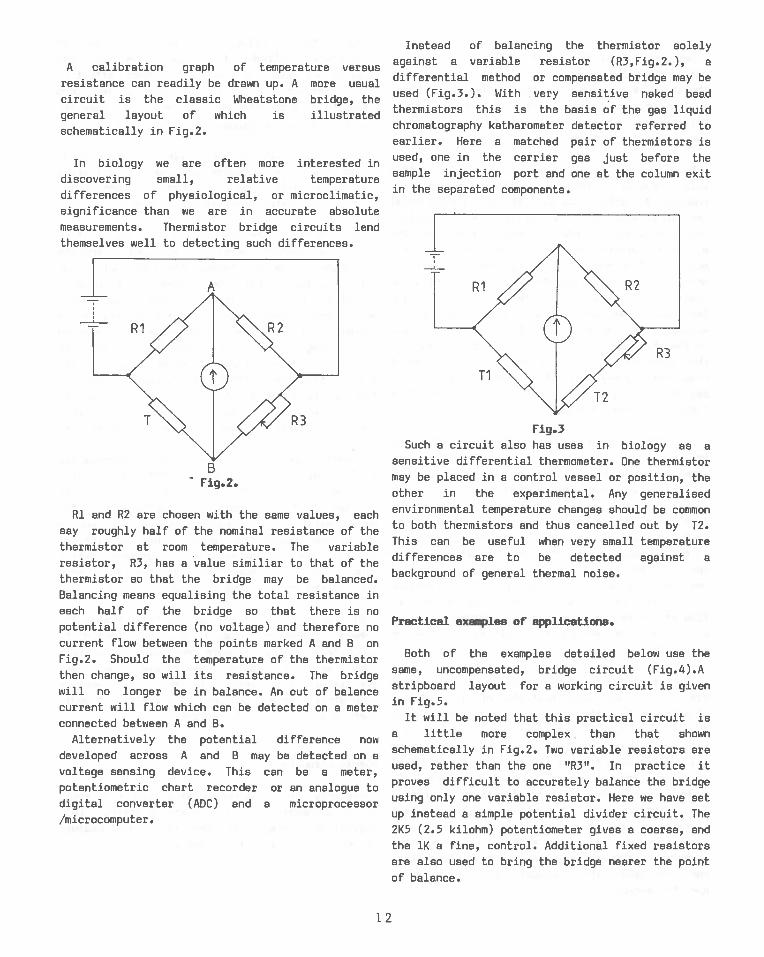
A calibration graph of temperature versusresistance can readily be drawn up. A more usualcircuit is the classic Wheatstone bridge, thegeneral layout of which is illustratedschematically in Fig.2.
In biology we are often more interested indiscovering small, relative temperature
differences of physiological, or microclimatic,
significance than we are in accurate absolute
measurements. Thermistor bridge circuits lendthemselves well to detecting such differences.
Ri and R2 are chosen with the same values, eachsay roughly half of the nominal resistance of thethermistor at room temperature. The variable
resistor, R3, has a value similiar to that of thethermistor so that the bridge may be balanced.Balancing means equalising the total resistance ineach half of the bridge so that there is nopotential difference (no voltage) and therefore nocurrent flow between the points marked A and B onFig.2. Should the temperature of the thermistorthen change, so will its resistance. The bridgewill no longer be in balance. An out of balancecurrent will flow which can be detected on a meterconnected between A and B.
Alternatively the potential difference nowdeveloped across A and B may be detected on a
voltage sensing device. This can be a meter,potentiometric chart recorder or an analogue to
digital converter (ADC) and a microprocessor
/microcomputer.
Instead of balancing the thermistor solely
against a variable resistor (R3,Fig.2.), adifferential method or compensated bridge may beused (Fig.3.). With very sensitive naked beadthermistors this is the basis of the gas liquidchromatography katharometer detector referred toearlier. Here a matched pair of thermistors isused, one in the carrier gas just before thesample injection port and one at the column exitin the separated components.
Practical examples of applications.
Both of the examples detailed below use the
same, uncompensated, bridge circuit (Fig.4).A
stripboard layout for a working circuit is given
in Fig.5.
It will be noted that this practical circuit isa little more complex than that shown
schematically in Fig.2. Two variable resistors are
used, rather than the one “R3”. In practice itproves difficult to accurately balance the bridgeusing only one variable resistor. Here we have set
up instead a simple potential divider circuit. The
2K5 (2.5 kilohm) potentiometer gives a coarse, and
the 1K a fine, control. Additional fixed resistors
are also used to bring the bridge nearer the point
of balance.
- Fig.2.
Fig.3Such a circuit also has uses in biology as a
sensitive differential thermometer. One thermistormay be placed in a control vessel or position, theother in the experimental. Any generalisedenvironmental temperature changes should be commonto both thermistors and thus cancelled out by T2.This can be useful when very small temperaturedifferences are to be detected against abackground of general thermal noise.
12
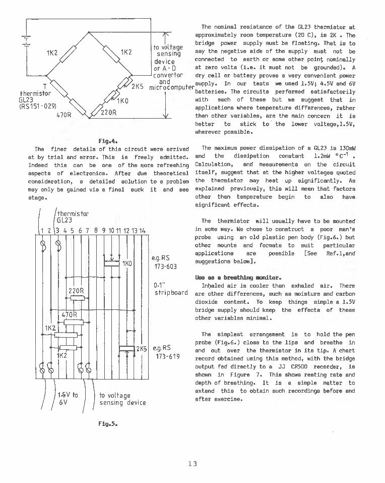
The nominal resistance of the 1123 thermistor atapproximately room temperature (20 C), is 2K • The
to yalta ebridge power supply must be floating. That is to
sensi4 say the negative side of the supply must not be
device connected to earth or some other point nominally
orA-D at zero volts (i.e. it must not be grounded). Aconvertor dry cell or battery proves a very convenient power
and supply. In our tests we used l.SV; 4.5V and 6V2KB microcomputerbatteries. The circuits performed satisfactorilywith each of these but we suggest that inapplications where temperature differences, ratherthan other variables, are the main concern it isbetter to stick to the lower voltage,l.5V,wherever possible.
Fiq.4.The maximum power dissipation of a 0L23 is 130mw
and the dissipation constant 1.2mW cc_I
Calculation, and measurements on the circuititself, suggest that at the higher voltages quotedthe thermistor may heat up significantly. Asexplained previously, this will mean that factorsother than temperature begin to also havesignificant effects.
The thermistor will usually have to be mountedin some way. we chose to construct a poor man’sprobe using an old plastic pen body (Fig.6.) butother mounts and formats to suit particularapplications are possible [See Ref.l,andsuggestions below].
lisa as a breathinq onttor.0.1” Inljaled air is cooler than exhaled air. Therestrip board are other differences, such as aoisture and carbon
dioxide content. To keep things simple a 1.5V
bridge supply should keep the effects of these
other variables minimal.
The simplest arrangement is to hold the penprobe (Fig.6.) close to the lips and breathe in
e.g.RS ar’d out over the thermistor in its tip. A chart173619 record obtained using this method, with the bridge
output fed directly to a JJ CR500 recorder, isshown in Figure 7. This shows resting rate and
depth of breathing. It is a simple matter to
extend this to obtain such recordings before and
after exercise.
The finer details of this circuit were arrived
at by trial and error. This is freely admitted.Indeed this can be one of the sore refreshing
aspects of electronics. After due theoretical
consideration, a detailed solution to a problem
may only be gained via a final suck it and see
stage.
/ thermistor6 L2 3
12
e.g.RS17 3-603
to voltagesensing device
Fig.5.
13
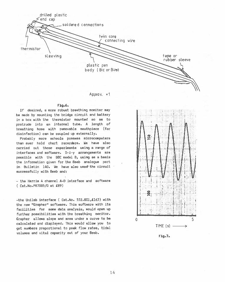
Fig.6.If desired, a more robust breathing monitor may
be made by mounting the bridge circuit and battery
in a box with the thermistor mounted so as to
protrude into an internal tube. A length of
breathing hose with removable mouthpiece (for
disinfection) can be coupled up externally.
Probably more schools possess microcomputers
than ever held chart recorders. We have also
carried out these experiments using a range of
interfaces and software. D—i—y arrangements are
possible with the BBC model B, using as a basis
the information given for the Beeb analogue port
in Bulletin 140. We have also use& the circuit
successfully with Beeb and:
— the Harris 4 channel A—D interface and software
Cat.No.P87005/0 at £89)
—the Unilab interface C Cat.No. 532.00l,fl63) with
the new “Grapher” software. This software with its
facilities for some data analysis, would open up
further possibilities with the breathing monitor.
Grapher allows slope and area under a curve to be
calculated and displayed. This would allow you to
get numbers proportional to peak flow rates, tidal
volumes and vital capacity out of your Beeb.
driLled plasticend cap
soldered connections
twin coreconnecting wire
sLeeving
plastic penbody C Bic orBir)
tape orrubber sleeve
Approx. xl
‘i
-— r — .
I
0 5
TIME (s)
Fig.7.
14
—the DCP ‘Interbeeb’ from Griffin (Cat.No.
CRA—950—0l0N,52—l3). The prototype Griffin
software did not include a suitable real time data
capture and plot routine. We therefore wrote our
own by extending Program 2 on page 8 of Bulletin
140, changing some lines to cater for the
different way of setting and reading the analogue
inputs on the Interbeeb. We found that the bridge
output needed to be amplified by hardware means
with a l.5V bridge voltage. With higher bridge
voltages, 4.5V and 6V, it was just possible to use
offset zero and amplification by software. This
meant instructing the Beeb to plot not the
straight value sitting on the A—D input but to
plot that value minus a fixed number multiplied by
an ‘amplification’ factor. Care was needed with
this. Too great a factor means that the inherent
inaccuracy of the A—D converter (±5%) becomes more
significant and too many spurious points get
plotted! (This subject will be dealt with more
fully in a future Bulletin).
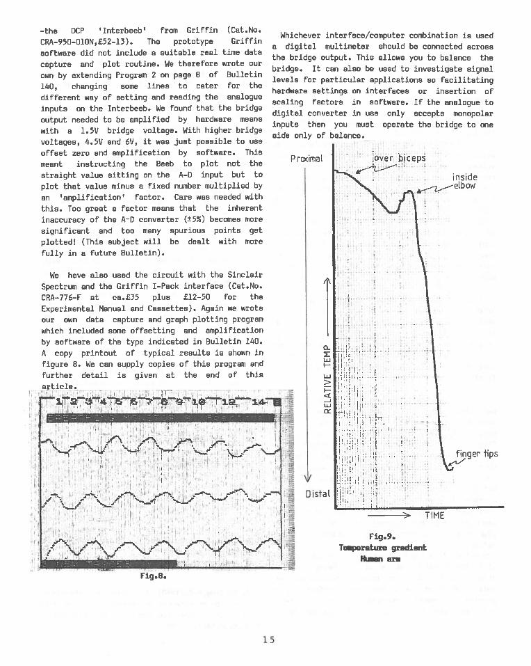
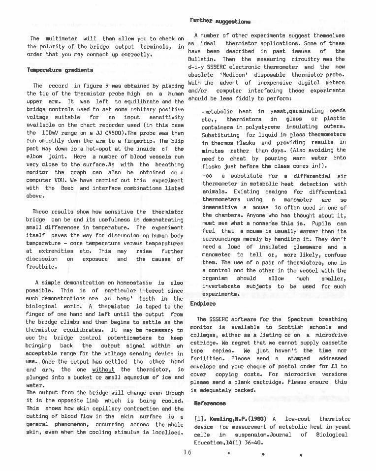
We have also used the circuit with the Sinclair
Spectrum and the Griffin I—Pack interface (Cat.No.
CRA—776—F at ca.35 plus £l2—50 for the
Experimental Manual and Cassettes). Again we wrote
our own data capture and graph plotting program
which included some offsetting and amplification
by software of the type indicated in Bulletin 140.
A copy printout of typical results is shown in
figure 8. We can supply copies of this program and
further detail is given at the end of this
article.11
Whichever interface/computer combination is useda digital multimeter should be connected acrossthe bridge output. This allows you to balance thebridge. It can also be used to investigate signallevels for particular applications so facilitatinghardware settings on interfaces or insertion ofscaling factors in software. If the analogue todigital converter in use only accepts monopolarinputs then you must operate the bridge to oneside only of balance.
:over bcep
I—
Fig.9.Te.perature gradient
Hi.en era
P rimal
Distal
(‘ :4
— I
tips
Fig.8.
> TIME
15
Further suggestions
The multimeter will then allow you to checkthe polarity of the bridge output terminals,order that you may connect up correctly.
Te.perature gradients
The record in figure 9 was obtained by placingthe tip of the thermistor probe high on a humanupper arm. It was left to equilibrate and thebridge controls used to set some arbitary positivevoltage suitable for an input sensitivityavailable on the chart recorder used (in this casethe lOOmV range on a JJ CR500).The probe was thenrun smoothly down the arm to a fingertip. The blippart way down is a hot—spot at the inside of theelbow joint. Here a number of blood vessels runvery close to the surface.As with the breathingmonitor the graph can also be obtained on acomputer VDLI. We have carried out this experimentwith the Beeb and interface combinations listedabove.
These results show how sensitive the thermistorbridge can be and its usefulness in demonstratingsmall differences in temperature. The experimentitself paves the way for discussion on human bodytemperature — core temperature versus temperaturesat extremities etc. This may raise furtherdiscussion on exposure and the causes offrostbite.
A simple demonstration on homeostasis is alsopossible. This is of particular interest sincesuch demonstrations are as hens’ teeth in thebiological world. A thermistor is taped to thefinger of one hand and left until the output fromthe bridge climbs and then begins to settle as thethermistor equilibrates. It may be necessary touse the bridge control potentiometers to keepbringing back the output signal within anacceptable range for the voltage sensing device inuse. , Once the output has settled the other hand
and arm, the one without the thermistor, is
plunged into a bucket or small aquarium of ice and
water.The output from the bridge will change even thoughit is the opposite limb which is being cooled.This shows how skin capillary contraction and thecutting of blood flow in the skin surface is ageneral phenomenon, occurring across the wholeskin, even when the cooling stimulus is localised.
onA number of other experiments suggest themselves
inas ideal thermistor applications. Some of these
have been described in past issues of the
Bulletin. Then the measuring circuitry was the
d—i—y SSSERC electronic thermometer and the now
obsolete ‘Nedicon’ disposable thermistor probe.
With the advent of inexpensive digital meters
and/or computer interfacing these experiments
should be less fiddly to perform:
—metabolic heat in yeast,germinating seeds
etc., thermistors in glass or plastic
containers in polystyrene insulating outers.
Substituting for liquid in glass thermometers
in thermos flasks and providing results in
minutes rather than days. (Also avoiding the
need to cheat by pouring warm water into
flasks just before the class comes in’).
—as a substitute for a differential airthermometer in metabolic heat detection withanimals. Existing designs for differentialthermometers using a manometer are soinsensitive a mouse is often used in one ofthe chambers. Anyone who has thought about it,must see what a nonsense this is. Pupils canfeel that a mouse is usually warmer than itssurroundings merely by handling it. They don’tneed a load of insulated glassware and amanometer to tell or, more likely, confusethem. The use of a pair of thermistors, one ina control and the other in the vessel with theorganism should allow much smaller,invertebrate subjects to be used for suchexperiments.
Endpiece
The SSSERC software for the Spectrum breathing
monitor is available to Scottish schools and
colleges, either as a listing or on a microdrive
catridge. We regret that we cannot supply cassette
tape copies. We just haven’t the time nor
facilities. Please send a stamped addressed
envelope and your cheque of postal order for £1 to
cover copying costs. For microdrive versions
please send a blank cartridge. Please ensure this
is adequately packed.
References
[1). Keeiing,R.P.(1980) A low—cost thermistor
device for measurement of metabolic heat in yeast
cells in suspension.Journal of Biological
Education.14(l) 36—40.
16 * * *


S.S.S.E.R.C.BULLETIN 141
JtJNE,1984CONTENTS
Page
Introduction —normal service as soon as possible 1
—research fellow 1
—Scottish young scientist 1
—MEDC courses 1
—Saturday opening 1.
—cost index 2
—errata bulletin 140 2
3CLEAPSE Guides
Safety Notes —seeing the light 3a shattering experience
Interfacing Notes —“Networking”, an MCC report
Science and the 4Handicapped Pupil
Project Suggestions 5
Egg Races 5
Foundation Science -solar power 6
Notes—toothpaste recipes a
Bio logy Notes —thermistor applications 10