equipped with aem installation instructions part number ... · pdf fileinstallation...
TRANSCRIPT

INSTALLATION INSTRUCTIONSPART NUMBER: 21-719
* NOTE: Legal in California only for racing vehicles which may never be used upon a highway AEM Induction Systems 1 (800) 992-3000 WWW: http://www.aemintakes.com
2007-2010 MINI Cooper S L4-1.6L W/O MAF SENSOR SEE NOTE*
Equipped with AEM® Dryflow™ FilterNo Oil Required!
2
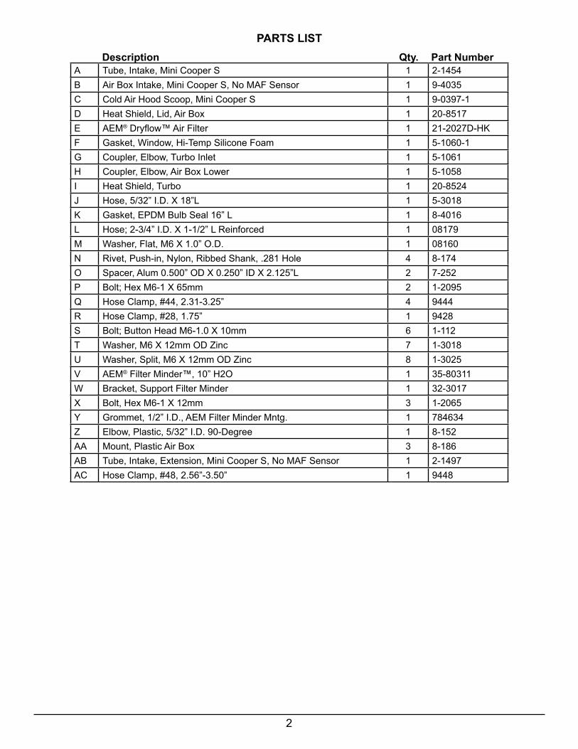
Description Qty. Part Number
PARTS LIST
A Tube, Intake, Mini Cooper S 1 2-1454B Air Box Intake, Mini Cooper S, No MAF Sensor 1 9-4035C Cold Air Hood Scoop, Mini Cooper S 1 9-0397-1D Heat Shield, Lid, Air Box 1 20-8517E AEM® Dryflow™ Air Filter 1 21-2027D-HKF Gasket, Window, Hi-Temp Silicone Foam 1 5-1060-1G Coupler, Elbow, Turbo Inlet 1 5-1061H Coupler, Elbow, Air Box Lower 1 5-1058I Heat Shield, Turbo 1 20-8524J Hose, 5/32” I.D. X 18”L 1 5-3018K Gasket, EPDM Bulb Seal 16” L 1 8-4016L Hose; 2-3/4” I.D. X 1-1/2” L Reinforced 1 08179M Washer, Flat, M6 X 1.0” O.D. 1 08160N Rivet, Push-in, Nylon, Ribbed Shank, .281 Hole 4 8-174O Spacer, Alum 0.500” OD X 0.250” ID X 2.125”L 2 7-252P Bolt; Hex M6-1 X 65mm 2 1-2095Q Hose Clamp, #44, 2.31-3.25” 4 9444R Hose Clamp, #28, 1.75” 1 9428S Bolt; Button Head M6-1.0 X 10mm 6 1-112T Washer, M6 X 12mm OD Zinc 7 1-3018U Washer, Split, M6 X 12mm OD Zinc 8 1-3025V AEM® Filter Minder™, 10” H2O 1 35-80311W Bracket, Support Filter Minder 1 32-3017X Bolt, Hex M6-1 X 12mm 3 1-2065Y Grommet, 1/2” I.D., AEM Filter Minder Mntg. 1 784634Z Elbow, Plastic, 5/32” I.D. 90-Degree 1 8-152AA Mount, Plastic Air Box 3 8-186AB Tube, Intake, Extension, Mini Cooper S, No MAF Sensor 1 2-1497AC Hose Clamp, #48, 2.56”-3.50” 1 9448

3
Kit Illustration

4
1. Preparing Vehicle a. Make sure vehicle is parked on level surface. b. Set parking brake. c. If engine has run in the past two hours, let it cool down. d. Disconnect negative battery terminal. e. Do not discard stock components after removal of the factory system. 2. Removal of stock system
Read and understand these instructions BEFORE attempting to install this product. Failureto follow installation instructions and not using the provided hardware may damage the intake tube, throttle body and engine.
a. Loosen the hose clamp connecting the intake tube to the stock air box.
b. Loosen the hose clamp connecting the intake tube to the turbo inlet. Disconnect the PCV hose to completely remove the intake tube.
c. Remove the lower Torx screw and plastic grom-met insert at the passenger side foot of the stock air box using a T20 Torx bit. Retain the Torx screw for future use.
The AEM® intake system is a performance product that can be used safely during mild weather conditions. During harsh and inclement weather conditions, you must return your vehicle to stock OEM air box and intake tract configuration. Failure to follow these instructions will void your warranty.
e. Pull up on the stock air box assembly carefully until it pops free from the 3 rubber mounting grom-mets on the intake manifold. Make sure all 3 rubber grommets stay in the intake manifold.

5
f. Unclip the plastic vacuum line from the lower intake elbow.
g. To completely remove the air box assembly, disconnect the air box inlet elbow (left) from the stock intake tube (right) by squeezing on the intake tube and pulling it free from the 4 locking slots in the intake elbow.

6
d. Mount the filter minder support bracket onto the brass inserts on the side of the air box using 2 of the M6 buttonhead bolts (S) and 2 of the split washers (U). Fully tighten the bolts with a 4mm allen wrench.
e. Mount the AEM® Filter Minder™ gauge (V) into the grommet of the support bracket and orient as shown. Use glass cleaner or a silicone lubricant to ease installation into the grommet. If necessary, reset the gauge needle so it points to the green section of the indicator.
3. Installation of AEM® Cold Air Intake System a. When installing the intake system, do not completely tighten the hose clamps or mounting hardware until instructed to do so.
b. Install the 3 black plastic airbox mounts (AA) onto the bottom of the air box (B) as shown using 3 of the M6 hex bolts (X) and 3 of the split washers (U) inside the air box. Fully tighten the 3 bolts and washers inside the air box.
c. Install the mounting grommet (Y) into the AEM® Filter Minder support bracket (W) as shown.

7
j. Install the 5/32” hose (J) over the elbow fitting as shown.
k. Install the filter assembly into the airbox with #48 hose clamp (AC) on the end. Push the #44 hose clamp already on the intake tube against the inside of the airbox and fully tighten it to seat the tube.
i. Install the small elbow fitting (Z) into the small hole in the cap of your AEM® Dryflow™ Air Filter (E) as shown.
f. Install the short reinforced hose (L) half-way onto the end of the intake tube extension (AB) and secure it with a #44 hose clamp (Q).
g. Insert the intake tube extension into the side of the airbox and loosely install another #44 hose clamp (Q) onto the tube inside the box.
l. Mount the Dryflow™ Air Filter onto the intake tube and fully tighten the hose clamp.

8
l. Push the 5/32” hose attached to the air filter through the 3/8” hole on the side of the air box and connect it to the port on the AEM® Filter Minder™ gauge as shown. Trim the hose as needed.
m. Install the OEM Torx bolt with one flat washer (T) and one split washer (U) into the airbox mount-ing foot as shown.
n. Install the large flat washer (M) onto the bolt under the foot mount to level the air box when installing the assembly onto the engine. Due to part variation, this may not be needed in some vehicles.
o. While holding the flat washer and Torx bolt in place, install the airbox assembly onto the 3 stock rubber grommets on the intake manifold. Thread the Torx bolt into the manifold by hand.
p. Tighten the Torx bolt into the intake manifold. Do not over tighten.
s. Install the oval end of the lower airbox inlet cou-pler (H) over the outlet of the stock plastic intake tube. Fully seat the intake tube until the 4 plastic lock tabs fit into the slots in rubber coupler.

9
r. Insert the round end of the elbow coupler (H) into the lower inlet hole in the air box. Make sure it is fully seated.
x. Remove the waxed paper backing from the silicone foam window gasket (F) by pinching the gasket on its sides, then pealing up the edge of exposed paper. DO NOT USE A KNIFE TOREMOVE THE PAPER BACKING.
y. Place the air box heat shield lid (D) on a table with the part number stamp facing DOWN. Apply the adhesive side of the silicone foam gasket on the heat shield, aligning it with the window cutout. Press down on the gasket to ensure adhesion. NOTE: The adhesive must set for 24 hours for best results.
z. Mount the heat shield lid assembly onto the air box using 4 M6 buttonhead bolts (S) and 4 flat washers (T). Tighten using a 4mm Allen wrench. Start all 4 bolts before fully tightening.

10
aa. Loosely install the turbo elbow coupler (G) onto the turbocharger inlet using the #28 hose clamp (R) provided. Fully seat the PCV connector into the bypass port of the coupler. Use glass cleaner to ease installation if necessary.
ab. Loosely install the intake tube (A) into the turbo coupler (G) and then into the short hose (L) on the air box using 2 #44 hose clamps (Q). Adjust the tube until it is straight alongside the engine and then fully tighten all 3 hose clamps.
ac. Assemble the 2 M6 x 65mm hex bolts (P), 2 flat washers (T), 2 split washers (U), and 2 aluminum spacers (O) so the hex bolts slide through the turbo heat shield (I) holes and into the aluminum spac-ers as shown. Assemble the parts so that the flat washers mount on top of the heat shield and the split washers are sandwiched by the heat shield and aluminum spacers.
ad. Mount the 2 long hex bolts of the turbo heat shield assembly into the 2 M6 mounting bosses at the edge of the cylinder head as shown. If you are installing an additional aftermarket valve cover heat shield to these two bosses, then do not install the split washers between the AEM® turbo heat shield and the aluminum spacers in the previous step.
ae. Fully tighten the 2 hex bolts. Pull up on the AEM® turbo heat shield (I) to ensure there is slight air gap between it and the stock turbo heat shield wrap. NOTE: The AEM® aluminum heat shield is required to protect your AEM® Cold Air Hood Scoop from excess heat.
11
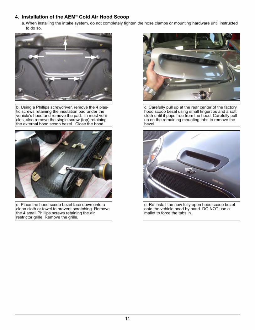
b. Using a Phillips screwdriver, remove the 4 plas-tic screws retaining the insulation pad under the vehicle’s hood and remove the pad. In most vehi-cles, also remove the single screw (top) retaining the external hood scoop bezel. Close the hood.
c. Carefully pull up at the rear center of the factory hood scoop bezel using small fingertips and a soft cloth until it pops free from the hood. Carefully pull up on the remaining mounting tabs to remove the bezel.
d. Place the hood scoop bezel face down onto a clean cloth or towel to prevent scratching. Remove the 4 small Phillips screws retaining the airrestrictor grille. Remove the grille.
e. Re-install the now fully open hood scoop bezel onto the vehicle hood by hand. DO NOT use a mallet to force the tabs in.
4. Installation of the AEM® Cold Air Hood Scoop a. When installing the intake system, do not completely tighten the hose clamps or mounting hardware until instructed to do so.

12
f. Install the rubber edge bulb trim (K) onto the lower lip and sides of the cold air hood scoop inlet (C). Cut the inner clamping edge of the trim and overlap it at the sharp bends if needed. Ensure the edge trim is even on both sides of the inlet and use the heel of your hand or a light rubber mallet to fully seat it.
g. Open the vehicle’s hood. Mount the AEM® cold air hood scoop onto the underside of the hood by inserting the plastic push rivets (N) through the mounting brackets and into the 4 insulator pad mounting holes by hand. Ensure the 4 push rivets are fully seated. Make sure the rubber edge bulb trim at the inlet fully seals along the cutout in the underside of the vehicle hood.
h. In some vehicles, you may need to unclip the windshield washer hose under the hood to prevent the hose from being pinched. Re-route the hose around the back of the new hood scoop and then re-clip the hose.
AEM® Cold Air Intake installed

13
5. Reassemble Vehicle a. Position the inlet pipes for the best fitment. Be sure that the pipes or any other components do not contact any part of the vehicle. Tighten the rubber mounts (if applicable), all bolts, and hose clamps. b. Check for proper hood clearance. Re-adjust pipes if necessary and re-tighten them. c. Inspect the engine bay for any loose tools and check that all fasteners that were moved or removed are properly tightened. d. Reconnect the negative battery terminal and start the engine. Let the vehicle idle for 3 minutes. Perform a final inspection before driving the vehicle.
6. Service and Maintenance a. AEM® Induction Systems requires cleaning the intake system’s air filter element every 100,000 miles. When used in dusty or off-road environments, our filters will require cleaning more often. We recommend that you visually inspect your filter once every 25,000 miles to determine if the screen is still visible. When the screen is no longer visible some place on the filter element, it is time to clean it. If your intake is equipped with an AEM Filter Minder Gauge: When the needle on the gauge points to the red zone, it is time to clean your filter. To clean, purchase our AEM® Synthetic Air Filter Cleaner, part number 1-1000 and follow the easy instructions. b. Use a damp cloth or window cleaner to clean your powder coated AEM® intake tube. NOTE: DO NOT USE aluminum polish on powder coated AEM® intake tubes.
For technical inquiriese-mail us at
call us at800.992.3000
7. AEM Air Intake System Warranty PolicyAEM® warrants that its intake systems will last for the life of your vehicle. AEM® will not honor this warranty due to me-chanical damage (i.e. improper installation or fitment), damage from misuse, accidents or flying debris. AEM will not war-rant its powder coating if the finish has been cleaned with a hydrocarbon-based solvent. The powder coating should only be cleaned with a mild soap and water solution. Proof of purchase of both the vehicle and AEM intake system is required for redemption of a warranty claim.
This warranty is limited to the repair or replacement of the AEM® part. In no event shall this warranty exceed the original purchase price of the AEM part nor shall AEM be responsible for special, incidental or consequential damages or cost incurred due to the failure of this product. Warranty claims to AEM must be transportation prepaid and accompanied with dated proof of purchase. This warranty applies only to the original purchaser of product and is nontransferable. Improper use or installation, use for racing, accident, abuse, unauthorized repairs or alterations voids this warranty. AEM disclaims any liability for consequential damages due to breach of any written or implied warranty on all products manufactured by AEM. Warranty returns will only be accepted by AEM when accompanied by a valid Return Merchandise Authorization (RMA) number. Credit for defective products will be issued pending inspection. Product must be received by AEM within 30 days of the date RMA is issued.
If you have a warranty issue, please call (800) 992-3000 and our customer service department will assist you. A proof of purchase is required for all AEM® warranty claims.
10-41103/22/13