equivalent air spring suspension model for quarter-passive ... · equivalent air spring suspension...
TRANSCRIPT

Research ArticleEquivalent Air Spring Suspension Model for Quarter-PassiveModel of Passenger Vehicles
Haider J Abid1 Jie Chen2 and Ameen A Nassar3
1Department of Mechanical Engineering Thi-Qar University Nasiriyah Iraq2Department of Mechanical Aerospace and Civil Engineering Brunel University Uxbridge UB8 3PH UK3Department of Mechanical Engineering Basrah University Basrah Iraq
Correspondence should be addressed to Haider J Abid haider-jabaurengutqeduiq
Received 15 January 2015 Revised 19 April 2015 Accepted 20 April 2015
Academic Editor Majid Ghassemi
Copyright copy 2015 Haider J Abid et al This is an open access article distributed under the Creative Commons Attribution Licensewhich permits unrestricted use distribution and reproduction in any medium provided the original work is properly cited
This paper investigates the GENSIS air spring suspension system equivalence to a passive suspension system The SIMULINKsimulation together with the OptiY optimization is used to obtain the air spring suspensionmodel equivalent to passive suspensionsystem where the car body response difference from both systemswith the same road profile inputs is used as the objective functionfor optimization (OptiY program)The parameters of air spring system such as initial pressure volume of bag length of surge pipediameter of surge pipe and volume of reservoir are obtained from optimization The simulation results show that the air springsuspension equivalent system can produce responses very close to the passive suspension system
1 Introduction
Suspension system design is a challenging task for theautomobile designers in view of multiple control parame-ters complex objectives (often conflicting) and stochasticdisturbances The problems stem from the wide range ofoperating conditions created by varying road conditionsvehicle speed and load [1] in general the road handling andsafety rules request harsh suspensions while the passengerscomfort feeling requires a soft dampingThere are three typesof suspension system passive systems semiactive systemsand active systems Each of the type of suspension hasdifferent advantages and disadvantages Passive suspensionsystems are subject to various tradeoffs when they are excitedacross a large frequency bandwidth [2] the disadvantageof a semiactive suspension where the system can be con-trolled only in one direction opposite to the velocity of thedamper extension [3] The active vibration control has thedisadvantages of complexity and high-energy consumptionThe air spring suspension systems can be used to overcomethese difficulties The air spring system is well known for itslow transmissibility coefficients and its ability to vary loadcapacities with only the change of the gas pressure within
the springs Air springs can be used for a mechatronicapproach in suspension design because of their ability toprovide a controlled variable spring rate and they offer simpleand inexpensive automatic leveling
One of the advantages of air springs is that the energy-storage capacity of air is far greater per unit weight thanthat of mechanical spring material such as steel Becauseof the efficient potential energy storage of springs of thistype their use in a vibration-isolation system can resultin a natural frequency for the system which is almost 10times lower than for a system employing vibration isolatorsmade from steel springs [4] This leads to the applicationswhere low frequency vibration isolation is necessary [5]Air springs have not only lower resonance frequencies butalso smaller over-all length than mechanical springs withequivalent characteristics [6] The ability to change the loadcarrying capacity simply by changing the air pressure ratherthan changing out the air spring is a major advantage thatair springs have over steel springs The air spring is mainlyused in commercial vehicles but lately it is also used in higherclasses of passenger vehicles
As discussed above the air spring suspension has anumber of advantages in real applicationHowever the design
Hindawi Publishing CorporationInternational Scholarly Research NoticesVolume 2015 Article ID 974020 6 pageshttpdxdoiorg1011552015974020
2 International Scholarly Research Notices
suspension system with air springs has been studied exten-sively On the contrary the design and analysis of the passivesuspension system are fully established Therefore the airspring suspension system design problem can be convertedto amodel which produces suspension performance the sameas a passive suspension system when using it without activecontroller or it can produce more efficient suspension systemwhen use it with active controller It is possible to converta passive suspension system to an air spring suspensionsystem and vice versa [7ndash12] The equivalence means thatboth systems have the similar suspension response for thesame road profile inputs
There have been some researches on the use of airspring for suspension systems For example Toyofuku et alshowed that the auxiliary chamber has a smaller effect onthe system [13] in high frequencies Bhave studied the effectsof pitch interconnection on vehicle performance and ridecomfort by using completed parametricmodeling [14] Crollaand Ramsbottom made some improvements in performancefor roll behavior of vehicle when he used electronicallycontrolled pneumatic suspension [15] Xiao et al developedforce-deflection relationship based on experimental data ofnonlinear air springmodel where the slidingmode controllerfor quarter carmodel is used for the half carmodel of a vehiclesuspension [16] The finite element method was used toanalyse the air spring stiffness byWu et al [17] Moreover thepaper [17] compared the stiffness of equivalent of air springmodel with stiffness of original model and discussed therelationship between inherent frequency and initial pressurebetween air spring stiffness and auxiliary chamber betweenair spring stiffness and different initial pressure The pressureof air supplied to the electropneumatic pressure regulator wascontrolled by regulating the voltage provider by Bhandariand Subramanian [18] Bruni et al investigated the dynamiccharacteristics of an air spring suspension with control [19]
The main objective of this study is to obtain an airspring suspension system which can replicate the passivesuspension system in terms of the suspension performanceIn this research an air spring suspension system is to be foundwhich can produce the performance better than VAMPICmodel [20] under the simulated quasistatic stiffness of thesuspension In the following part of the paper the mathe-matical models for both air spring and passive suspension arepresented in Section 2 and the optimization method is usedto find air spring suspension model parameters in Section 3
2 Air Suspension SystemMathematical Model and Its PassiveSuspension System Equivalence
21 Air Suspension System The basis for mathematical mod-els of air springs is to measure its mechanical propertiesThe mechanical behavior of air springs is often very com-plicated The behavior is mainly based on fluid dynamic andthermodynamic mechanisms where important quantities insuch mechanisms are pressure volume temperature massflow rate density and energy of the air as well as shape ofthe air volume For most air springs these quantities should
14 3 2
5
Figure 1 Air spring suspension system (1) reservoir (2) controlledvalve (3) surge pipe (4) air bag and (5) tire
be expressed for both the air spring itself and its reservoirvolume as shown in Figure 1
22 Air SpringModeling There aremany different kinds of airspring models such as a simple model for vertical air springdynamics (Nishimura [6] VAMPIRE [21] SIMPAC [22]and GENSYS [23 24]) The air spring system as illustratedin Figure 1 consists of an air bag connected to a reservoirby a pipeline system and a controlled valve The systemrsquosstiffness can be changed The modeling of an air springpresented here does not take in consideration the levelingsystem because these changes are very slow The mathe-matical models incorporate the stiffness and the dampingcharacteristics of the air spring Under the vibrations thebehavior of the compressed air within the air spring systemis polytropic The minimal stiffness is reached when there isan isothermal change of the gas state (for frequencies 119891 lt01Hz) and the maximal stiffness is associated with adiabaticstate change (for frequencies 119891 gt 3Hz) The analysis of thevehicle vertical dynamics shows a special interest around thefrequency domain from 0 to 20Hz [6]
In order to consider the change in the gas state in the twovolumes an approximation has been introduced by imple-menting a mechanical barrier (fictive piston) in the pipelineThe mechanical barrier is considered to be with neglectedmass and equivalent fluid mass that is moving through thepipeline is added to the barrier [5] This approximation isjustified because small amount of fluid oscillates between thetwo volumes
The following analysis follows the method of calculationin [25] with the simplified air spring system shown inFigure 2 After a defection the new air bag volume and newreservoir volume with polytropic process we get
∵ 119881119887 = 119881bi minus 119911119860119890 + 119911fp119860 119904
119881119903 = 119881ri minus 119911fp119860 119904(1)
International Scholarly Research Notices 3
Vb pb Ae
z
zfp Vri pr
Figure 2 Modeling of air suspension spring
Fz
bz
z
z1M
cz2
cz1
Fst
Figure 3 The mechanical model of air suspension system [6]
where 119911 is the deflection of air bag 119911fp is the the displacementof air in surge pipe119860119890 is the the effective area of air bag119860 119904 isthe the cross section area of the pipeline 119881bi is the the initialvolume of air bag 119881ri is the the initial volume of reservoir
The GENSYS model of the air suspension system asshown in Figure 3 has polytrope gas state change [6] For thismode the static load and the stiffness constants 1198621199111 1198621199112119872and 119887119911 can be identified as
1198621199111 =119901119894119860
2119890119899
119881bi + 119881ri
1198621199112 =119901119894119860
2119890119899
119881bi + 119881ri
119881ri119881bi= 1198621199112
119881ri119881bi
119872 = 119897119904119860 119904120588(119860119890119860 119904
119881ri119881bi + 119881ri
)2
(2)
msms
mu
mu
ks
kt
cs
ct
zs
zu
zr
Fk119904Fc119904
Fk119905Fk119905
Figure 4 Quarter-car model and relevant free body diagram
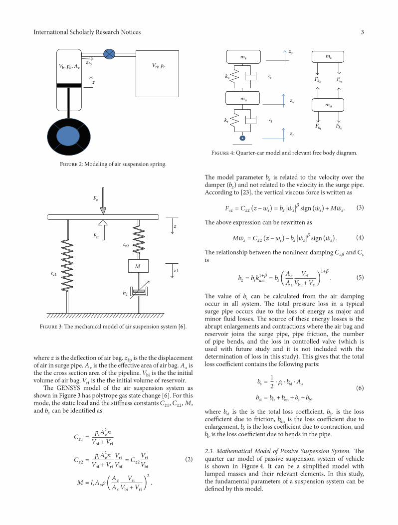
The model parameter 119887119911 is related to the velocity over thedamper (119887119911) and not related to the velocity in the surge pipeAccording to [23] the vertical viscous force is written as
119865V119911 = 1198621199112 (119911 minus119908119904) = 11988711991110038161003816100381610038161199041003816100381610038161003816120573 sign (119904) +119872119904 (3)
The above expression can be rewritten as
119872119904 = 1198621199112 (119911 minus119908119904) minus 11988711991110038161003816100381610038161199041003816100381610038161003816120573 sign (119904) (4)
The relationship between the nonlinear damping 119862119911120573 and 119862119904is
119887119911 = 1198871199041198961+120573119908119911= 119887119904 (
119860119890119860 119904
119881ri119881bi + 119881ri
)1+120573 (5)
The value of 119887119904 can be calculated from the air dampingoccur in all system The total pressure loss in a typicalsurge pipe occurs due to the loss of energy as major andminor fluid losses The source of these energy losses is theabrupt enlargements and contractions where the air bag andreservoir joins the surge pipe pipe friction the numberof pipe bends and the loss in controlled valve (which isused with future study and it is not included with thedetermination of loss in this study) This gives that the totalloss coefficient contains the following parts
119887119904 =12sdot 120588119894 sdot 119887st sdot 119860 119904
119887st = 119887fr + 119887en + 119887119888 + 119887119887
(6)
where 119887st is the is the total loss coefficient 119887fr is the losscoefficient due to friction 119887en is the loss coefficient due toenlargement 119887119888 is the loss coefficient due to contraction and119887119887 is the loss coefficient due to bends in the pipe
23 Mathematical Model of Passive Suspension System Thequarter car model of passive suspension system of vehicleis shown in Figure 4 It can be a simplified model withlumped masses and their relevant elements In this studythe fundamental parameters of a suspension system can bedefined by this model
4 International Scholarly Research Notices
Air spring suspension system model with
adjustable parameters
Passive suspension system model with
fixed parameters
OptimizationRoad profile
input
Displacement
DisplacementSIMULINK
OptiY
+
minus
Figure 5 Finding equivalent model using SIMULINK simulationand OptiY optimization
Nonlinear equations of the sprung mass and unsprungmass motions can be derived in two parts as follows [26]
Sprung mass equation
119898119904 = minus 119896119904 (119911119904 minus 119911119906) minus 120577119896119904 (119911119904 minus 119911119906)3minus 119888119904 ( 119911119904 minus 119911119906)
minus 120577119888119904 ( 119911119904 minus 119911119906)2 sgn ( 119911119904 minus 119911119906)
(7)
Unsprung mass equation
119898119906 119911119906 = 119896119904 (119911119904 minus 119911119906) + 120577119896119904 (119911119904 minus 119911119906)3+ 119888119904 ( 119911119904 minus 119911119906)
+ 120577119888119904 ( 119911119904 minus 119911119906)2 sgn ( 119911119904 minus 119911119906) minus 119896119905 (119911119906 minus 119911119903)
minus 120577119896119905 (119911119906 minus 119911119903)3minus 119888119905 ( 119911119906 minus 119903)
minus 120577119888119905 ( 119911119906 minus 119911119903)2 sgn ( 119911119906 minus 119911119903)
(8)
where 119865119896119904
is the nonlinear force of coil springs (N) 119865119888119904
is thenonlinear forces of damper (N) 119865119896
119905
is the the spring force oftire (N) 119865119888
119905
is the the damping force of tire (N) 119898119904 is themass of vehiclersquos body (kg) 119898119906 is the mass of wheel (kg)119896119904 is the stiffness of spring (Nm) 119896119905 is the stiffness of tire(Nm) 119888119904 is the damping coefficient of damper (Nsdotsm) 119888119905 isthe damping coefficient of tire (Nsdots m) 119911119904 is the displacementof vehiclersquos body (m) 119911119906 is the displacement of wheel (m)119911119903 is the displacement of road profile (m) 120577 is the empiricalparameter
3 Obtain Equivalent Air Spring SuspensionModel Using Optimization
The idea of equivalent model is to find an air spring sus-pension system configuration which produces the same sus-pension performance (displacement) as a passive suspensionsystem count part with the same road profile inputs (if thepassive mode is selected that means without controller) Thisis achieved by finding air spring systemmodel parameters byminimizing the performance difference
The process of obtaining the equivalent model is illus-trated by Figure 5 where the response of both air spring sus-pension and passive suspension models are simulated usingSIMULINK The OptiY optimization program is used toadjust air suspension model parameters so that the responsedifference is minimized The air suspension model param-eters to be found are initial pressure in system volume ofbag length of surge pipe diameter of surge pipe and volume
Table 1 The lower bound and the upper bound of the constraintparameters
Parameter Lowerbound
Upperbound Unit
Initial pressure (in bag andreservoir) 100000 700000 kPa
Bag diameter 005 02 mBag height 01 075 mReservoir volume 001 03 m3
Length of surge pipe 1 5 mDiameter of surge pipe 0003 0025 m
Figure 6 The results of OptiY software with MATLABSimulink
0 2 4 6 8 10 12 14 16 18 20
0
05
1
15
2
Time (s)
Disp
lace
men
t (cm
)
RoadZasZap
minus15
minus05
minus1
Figure 7 The response of optimization technique with sine waveroad profile
of reservoir The optimization is a constraint optimizationproblem where the design parameter constraints are given inTable 1
The parameter values of the quarter passive vehiclemodelused in the simulation are taken from [27] The road profileused in this study is sine square and saw tooth waveswith amplitude 10 cm and frequency of 1Hz The optimiza-tion technique is implemented with 3000 attempts and theSIMULINK simulate the systemswith 20 seconds periodTheoptimal parameters found are presented in Table 2
The system responses for passive and optimized air springsuspension systems are presented in Figure 6 The responseof equivalent air spring suspension system with sine waveroad profile square road profile and random road profile areshown in Figures 7ndash9
International Scholarly Research Notices 5
Table 2 The numerical values of the passive suspension system
Notations Description Values Units1198701 1198702 Front-left and front-right suspension stuffiness respectively 19960 Nm1198703 1198704 Rear-left and Rear-right suspension stuffiness respectively 17500 Nm1198961ndash1198964 Front-left and front-right and rear-right and rear-left tire stuffiness respectively 175500 Nm1198621 1198622 Front-left and front-right suspension damping respectively 1290 Nsdotsm1198623 1198624 Rear-left and rear-right suspension damping respectively 1690 Nsdotsm1198881ndash1198884 Front-left and front-right and rear-right and rear-left tire damping respectively 146 Nsdotsm119872 Sprung mass 1460 Kg1198981-1198982 Front-left and front-right tire mass respectively 40 Kg1198983-1198984 Rear-left and Rear-right tire mass respectively 355 Kg119869119909 Moment of inertia 119909-direction 460 Kgsdotm2
119869119910 Moment of inertia 119910-direction 2460 Kgsdotm2
1198971 Distance between the center of gravity of vehicle body and front axle 1011 m1198972 Distance between the center of gravity of vehicle body and rear axle 1803 m119887 Width of track 151 m
0 2 4 6 8 10 12 14 16 18 20
0
05
1
15
Time (s)
Disp
lace
men
t (cm
)
Road ZasZap
minus15
minus05
minus1
Figure 8The response of optimization technique with square waveroad profile
Time (s)0 2 4 6 8 10 12 14 16 18 20
0
05
1
15
Disp
lace
men
t (cm
)
RoadZasZps
minus15
minus05
minus1
Figure 9 The response of optimization technique with saw toothwave road profile
4 Conclusion
The optimization technique available in OptiY withSIMULINK simulation was successfully used in this paperto find the equivalent air spring suspension model withthe optimized parameters The results are shown that theequivalent model can produce the suspension responsesimilar to the passive suspension system In future studiesthe model can be used in active air suspension system designfor better handling and stability properties The nature oflow resonance frequency in air spring can be exploited byfrequency domain controller design methods such as Hinfinmethods [28]
Conflict of Interests
The authors declare that they have no conflict of interestsregarding the publication of this paper
References
[1] H M Zheng L H Zhu and N D D Dong ldquoInvestigation onon-off damping control law of vibration isolatorrdquo in Proceedingsof the International Conference on Mechanics and MaterialsEngineering (ICMME rsquo14) pp 176ndash182 Phuket IslandThailandOctober 2014
[2] B Chandekar and H D Lagdive ldquoDesign of electro-hydraulicactive suspension system for four wheel vehiclesrdquo InternationalJournal of Emerging Technology and Advanced Engineering vol4 no 4 pp 885ndash889 2014
[3] D P Krishnasamy J Jayaraj and D John ldquoExperimentalinvestigation on road vehicle active suspensionrdquo Journal ofMechanical Engineering vol 59 no 10 pp 620ndash625 2013
[4] CMHarris andA G Piersol EdsHarrisrsquo Shock and VibrationHandbook McGraw-Hill New York NY USA 5th edition2002
6 International Scholarly Research Notices
[5] V Gavriloski E Vetadzokoska N Babamov and J JovanovaldquoDevelopment of air spring dynamic model for vehicle suspen-sionrdquoMechanical EngineeringmdashScientific Journal vol 28 no 2pp 89ndash94 2009
[6] M Presthus Derivation of air spring model parameters for trainsimulation [MS thesis] Lulea University of Technology 2002
[7] Air SuspensionConversion Systems httpwwwsuncoreindus-triescomsuspension-conversion-systemsphp
[8] (nd) October 2014 Suspension-Alternativecom httpsuspensionalternativeswordpresscom
[9] eCustomhitch (nd) 2014 httpecustomhitchcom[10] httpunityautomotiveco[11] Arnott Europe Air Suspension Products 1989 httpswww
arnotteuropecom[12] Air Left Suspension Air Suspension 1999 httpwww
airsuspensioncom[13] K Toyofuku C Yamada T Kagawa and T Fujita ldquoStudy
on dynamic characteristic analysis of air spring with auxiliarychamberrdquo JSAE Review vol 20 no 3 pp 349ndash355 1999
[14] S Y Bhave ldquoEffect of connecting the front and rear air sus-pensions of a vehicle on the transmissibility of road undulationinputsrdquo Vehicle System Dynamics vol 21 no 4 pp 225ndash2451992
[15] D A Crolla and M Ramsbottom Development and Analysis ofa Prototype Controllable Suspension SI Society of AutomotiveEngineers Warrendale Pa USA 1997
[16] J Xiao B T Kulakowski and M Cao ldquoActive air-suspensiondesign for transit busesrdquo International Journal of Heavy VehicleSystems vol 14 no 4 pp 421ndash440 2007
[17] J Wu W Shangguan and X Pan ldquoComputational methodfor dynamic properties of rubber isolators using hyperelastic-viscoelastic-plastoelastic constitutive modelrdquo Journal ofMechanical Engineering vol 46 no 14 pp 109ndash114 2010
[18] V Bhandari and S C Subramanian ldquoDevelopment of anelectronically controlled pneumatic suspension for commercialvehiclesrdquo in Proceedings of the IEEE International Conference onPower Control and Embedded Systems (ICPCES rsquo10) December2010
[19] S Bruni J Vinolas M Berg O Polach and S Stichel ldquoMod-elling of suspension components in a rail vehicle dynamicscontextrdquo Journal of Vehicle System Dyanmics vol 49 no 7 pp1021ndash1072 2011
[20] L Liu and W Z Li ldquoResearch on stiffness of air-spring withauxiliary chamber and its equivalent modelrdquo in Proceedingsof the 11th International Conference on Vibration Problems ZDimitrovova J R de Almeida and R Goncalves Eds pp 1ndash8Lisbon Portugal 2013
[21] S Eaton A Mathematical Model of a Nonlinear PneumaticSuspension System ABB Daimler-Benz Transportation (RollingStock) Berlin Germany 1997
[22] D Vannucci G Saporito and M Romani ldquoWheel raildynamic of DMU IC4 car for DSB modelling of the effectof secondary air spring on calculation results and advancedanalysis for controlling car body anglerdquo in Proceedingsof the SIMPACK User Meeting March 2006 httpwwwsimpackcomfileadminsimpackdocusermeeting06um06ansaldob-saporitopdf
[23] M Berg ldquoA three-dimensional air spring model with frictionand orifice dampingrdquo in Proceedings of the 16th IA VSDSymposium the Dynamics of Vehicles on Roads and on TracksPretoria South Africa 1999
[24] M Berg ldquoAn air spring model for dynamic analysis of railvehiclesrdquo TRITA-FKT Report 199932 Division of RailwayTechnology Department of Vehicle Engineering Royal Insti-tute of Technology Stockholm Sweden 1999
[25] P Sundvall ldquoComparisons between predicted and measuredride comfort in trainsmdasha case study on modelingrdquo TRITA-FKT Report Division of Railway Technology Department ofVehicle Engineering Royal Institute of Technology StockholmSweden 2001
[26] S ShahriarDevelopment and evaluation of a semi-active suspen-sion system for full suspension tractors [PhD thesis] TechnischeUniversity Berlin 2009
[27] A A Aldair Neurofuzzy controller based full vehicle nonlinearactive suspension systems [PhD thesis] School of Engineeringand Informatics University of Sussex Brighton UK 2012
[28] W Sun H Gao and O Kaynak ldquoFinite frequency 119867infin controlfor vehicle active suspension systemsrdquo IEEE Transactions onControl Systems Technology vol 19 no 2 pp 416ndash422 2011
Submit your manuscripts athttpwwwhindawicom
VLSI Design
Hindawi Publishing Corporationhttpwwwhindawicom Volume 2014
International Journal of
RotatingMachinery
Hindawi Publishing Corporationhttpwwwhindawicom Volume 2014
Hindawi Publishing Corporation httpwwwhindawicom
Journal ofEngineeringVolume 2014
Hindawi Publishing Corporationhttpwwwhindawicom Volume 2014
Shock and Vibration
Hindawi Publishing Corporationhttpwwwhindawicom Volume 2014
Mechanical Engineering
Advances in
Hindawi Publishing Corporationhttpwwwhindawicom Volume 2014
Civil EngineeringAdvances in
Acoustics and VibrationAdvances in
Hindawi Publishing Corporationhttpwwwhindawicom Volume 2014
Hindawi Publishing Corporationhttpwwwhindawicom Volume 2014
Electrical and Computer Engineering
Journal of
Hindawi Publishing Corporationhttpwwwhindawicom Volume 2014
Distributed Sensor Networks
International Journal of
The Scientific World JournalHindawi Publishing Corporation httpwwwhindawicom Volume 2014
SensorsJournal of
Hindawi Publishing Corporationhttpwwwhindawicom Volume 2014
Modelling amp Simulation in EngineeringHindawi Publishing Corporation httpwwwhindawicom Volume 2014
Hindawi Publishing Corporationhttpwwwhindawicom Volume 2014
Active and Passive Electronic Components
Hindawi Publishing Corporationhttpwwwhindawicom Volume 2014
Chemical EngineeringInternational Journal of
Control Scienceand Engineering
Journal of
Hindawi Publishing Corporationhttpwwwhindawicom Volume 2014
Antennas andPropagation
International Journal of
Hindawi Publishing Corporationhttpwwwhindawicom Volume 2014
Hindawi Publishing Corporationhttpwwwhindawicom Volume 2014
Navigation and Observation
International Journal of
Advances inOptoElectronics
Hindawi Publishing Corporation httpwwwhindawicom
Volume 2014
RoboticsJournal of
Hindawi Publishing Corporationhttpwwwhindawicom Volume 2014

2 International Scholarly Research Notices
suspension system with air springs has been studied exten-sively On the contrary the design and analysis of the passivesuspension system are fully established Therefore the airspring suspension system design problem can be convertedto amodel which produces suspension performance the sameas a passive suspension system when using it without activecontroller or it can produce more efficient suspension systemwhen use it with active controller It is possible to converta passive suspension system to an air spring suspensionsystem and vice versa [7ndash12] The equivalence means thatboth systems have the similar suspension response for thesame road profile inputs
There have been some researches on the use of airspring for suspension systems For example Toyofuku et alshowed that the auxiliary chamber has a smaller effect onthe system [13] in high frequencies Bhave studied the effectsof pitch interconnection on vehicle performance and ridecomfort by using completed parametricmodeling [14] Crollaand Ramsbottom made some improvements in performancefor roll behavior of vehicle when he used electronicallycontrolled pneumatic suspension [15] Xiao et al developedforce-deflection relationship based on experimental data ofnonlinear air springmodel where the slidingmode controllerfor quarter carmodel is used for the half carmodel of a vehiclesuspension [16] The finite element method was used toanalyse the air spring stiffness byWu et al [17] Moreover thepaper [17] compared the stiffness of equivalent of air springmodel with stiffness of original model and discussed therelationship between inherent frequency and initial pressurebetween air spring stiffness and auxiliary chamber betweenair spring stiffness and different initial pressure The pressureof air supplied to the electropneumatic pressure regulator wascontrolled by regulating the voltage provider by Bhandariand Subramanian [18] Bruni et al investigated the dynamiccharacteristics of an air spring suspension with control [19]
The main objective of this study is to obtain an airspring suspension system which can replicate the passivesuspension system in terms of the suspension performanceIn this research an air spring suspension system is to be foundwhich can produce the performance better than VAMPICmodel [20] under the simulated quasistatic stiffness of thesuspension In the following part of the paper the mathe-matical models for both air spring and passive suspension arepresented in Section 2 and the optimization method is usedto find air spring suspension model parameters in Section 3
2 Air Suspension SystemMathematical Model and Its PassiveSuspension System Equivalence
21 Air Suspension System The basis for mathematical mod-els of air springs is to measure its mechanical propertiesThe mechanical behavior of air springs is often very com-plicated The behavior is mainly based on fluid dynamic andthermodynamic mechanisms where important quantities insuch mechanisms are pressure volume temperature massflow rate density and energy of the air as well as shape ofthe air volume For most air springs these quantities should
14 3 2
5
Figure 1 Air spring suspension system (1) reservoir (2) controlledvalve (3) surge pipe (4) air bag and (5) tire
be expressed for both the air spring itself and its reservoirvolume as shown in Figure 1
22 Air SpringModeling There aremany different kinds of airspring models such as a simple model for vertical air springdynamics (Nishimura [6] VAMPIRE [21] SIMPAC [22]and GENSYS [23 24]) The air spring system as illustratedin Figure 1 consists of an air bag connected to a reservoirby a pipeline system and a controlled valve The systemrsquosstiffness can be changed The modeling of an air springpresented here does not take in consideration the levelingsystem because these changes are very slow The mathe-matical models incorporate the stiffness and the dampingcharacteristics of the air spring Under the vibrations thebehavior of the compressed air within the air spring systemis polytropic The minimal stiffness is reached when there isan isothermal change of the gas state (for frequencies 119891 lt01Hz) and the maximal stiffness is associated with adiabaticstate change (for frequencies 119891 gt 3Hz) The analysis of thevehicle vertical dynamics shows a special interest around thefrequency domain from 0 to 20Hz [6]
In order to consider the change in the gas state in the twovolumes an approximation has been introduced by imple-menting a mechanical barrier (fictive piston) in the pipelineThe mechanical barrier is considered to be with neglectedmass and equivalent fluid mass that is moving through thepipeline is added to the barrier [5] This approximation isjustified because small amount of fluid oscillates between thetwo volumes
The following analysis follows the method of calculationin [25] with the simplified air spring system shown inFigure 2 After a defection the new air bag volume and newreservoir volume with polytropic process we get
∵ 119881119887 = 119881bi minus 119911119860119890 + 119911fp119860 119904
119881119903 = 119881ri minus 119911fp119860 119904(1)
International Scholarly Research Notices 3
Vb pb Ae
z
zfp Vri pr
Figure 2 Modeling of air suspension spring
Fz
bz
z
z1M
cz2
cz1
Fst
Figure 3 The mechanical model of air suspension system [6]
where 119911 is the deflection of air bag 119911fp is the the displacementof air in surge pipe119860119890 is the the effective area of air bag119860 119904 isthe the cross section area of the pipeline 119881bi is the the initialvolume of air bag 119881ri is the the initial volume of reservoir
The GENSYS model of the air suspension system asshown in Figure 3 has polytrope gas state change [6] For thismode the static load and the stiffness constants 1198621199111 1198621199112119872and 119887119911 can be identified as
1198621199111 =119901119894119860
2119890119899
119881bi + 119881ri
1198621199112 =119901119894119860
2119890119899
119881bi + 119881ri
119881ri119881bi= 1198621199112
119881ri119881bi
119872 = 119897119904119860 119904120588(119860119890119860 119904
119881ri119881bi + 119881ri
)2
(2)
msms
mu
mu
ks
kt
cs
ct
zs
zu
zr
Fk119904Fc119904
Fk119905Fk119905
Figure 4 Quarter-car model and relevant free body diagram
The model parameter 119887119911 is related to the velocity over thedamper (119887119911) and not related to the velocity in the surge pipeAccording to [23] the vertical viscous force is written as
119865V119911 = 1198621199112 (119911 minus119908119904) = 11988711991110038161003816100381610038161199041003816100381610038161003816120573 sign (119904) +119872119904 (3)
The above expression can be rewritten as
119872119904 = 1198621199112 (119911 minus119908119904) minus 11988711991110038161003816100381610038161199041003816100381610038161003816120573 sign (119904) (4)
The relationship between the nonlinear damping 119862119911120573 and 119862119904is
119887119911 = 1198871199041198961+120573119908119911= 119887119904 (
119860119890119860 119904
119881ri119881bi + 119881ri
)1+120573 (5)
The value of 119887119904 can be calculated from the air dampingoccur in all system The total pressure loss in a typicalsurge pipe occurs due to the loss of energy as major andminor fluid losses The source of these energy losses is theabrupt enlargements and contractions where the air bag andreservoir joins the surge pipe pipe friction the numberof pipe bends and the loss in controlled valve (which isused with future study and it is not included with thedetermination of loss in this study) This gives that the totalloss coefficient contains the following parts
119887119904 =12sdot 120588119894 sdot 119887st sdot 119860 119904
119887st = 119887fr + 119887en + 119887119888 + 119887119887
(6)
where 119887st is the is the total loss coefficient 119887fr is the losscoefficient due to friction 119887en is the loss coefficient due toenlargement 119887119888 is the loss coefficient due to contraction and119887119887 is the loss coefficient due to bends in the pipe
23 Mathematical Model of Passive Suspension System Thequarter car model of passive suspension system of vehicleis shown in Figure 4 It can be a simplified model withlumped masses and their relevant elements In this studythe fundamental parameters of a suspension system can bedefined by this model
4 International Scholarly Research Notices
Air spring suspension system model with
adjustable parameters
Passive suspension system model with
fixed parameters
OptimizationRoad profile
input
Displacement
DisplacementSIMULINK
OptiY
+
minus
Figure 5 Finding equivalent model using SIMULINK simulationand OptiY optimization
Nonlinear equations of the sprung mass and unsprungmass motions can be derived in two parts as follows [26]
Sprung mass equation
119898119904 = minus 119896119904 (119911119904 minus 119911119906) minus 120577119896119904 (119911119904 minus 119911119906)3minus 119888119904 ( 119911119904 minus 119911119906)
minus 120577119888119904 ( 119911119904 minus 119911119906)2 sgn ( 119911119904 minus 119911119906)
(7)
Unsprung mass equation
119898119906 119911119906 = 119896119904 (119911119904 minus 119911119906) + 120577119896119904 (119911119904 minus 119911119906)3+ 119888119904 ( 119911119904 minus 119911119906)
+ 120577119888119904 ( 119911119904 minus 119911119906)2 sgn ( 119911119904 minus 119911119906) minus 119896119905 (119911119906 minus 119911119903)
minus 120577119896119905 (119911119906 minus 119911119903)3minus 119888119905 ( 119911119906 minus 119903)
minus 120577119888119905 ( 119911119906 minus 119911119903)2 sgn ( 119911119906 minus 119911119903)
(8)
where 119865119896119904
is the nonlinear force of coil springs (N) 119865119888119904
is thenonlinear forces of damper (N) 119865119896
119905
is the the spring force oftire (N) 119865119888
119905
is the the damping force of tire (N) 119898119904 is themass of vehiclersquos body (kg) 119898119906 is the mass of wheel (kg)119896119904 is the stiffness of spring (Nm) 119896119905 is the stiffness of tire(Nm) 119888119904 is the damping coefficient of damper (Nsdotsm) 119888119905 isthe damping coefficient of tire (Nsdots m) 119911119904 is the displacementof vehiclersquos body (m) 119911119906 is the displacement of wheel (m)119911119903 is the displacement of road profile (m) 120577 is the empiricalparameter
3 Obtain Equivalent Air Spring SuspensionModel Using Optimization
The idea of equivalent model is to find an air spring sus-pension system configuration which produces the same sus-pension performance (displacement) as a passive suspensionsystem count part with the same road profile inputs (if thepassive mode is selected that means without controller) Thisis achieved by finding air spring systemmodel parameters byminimizing the performance difference
The process of obtaining the equivalent model is illus-trated by Figure 5 where the response of both air spring sus-pension and passive suspension models are simulated usingSIMULINK The OptiY optimization program is used toadjust air suspension model parameters so that the responsedifference is minimized The air suspension model param-eters to be found are initial pressure in system volume ofbag length of surge pipe diameter of surge pipe and volume
Table 1 The lower bound and the upper bound of the constraintparameters
Parameter Lowerbound
Upperbound Unit
Initial pressure (in bag andreservoir) 100000 700000 kPa
Bag diameter 005 02 mBag height 01 075 mReservoir volume 001 03 m3
Length of surge pipe 1 5 mDiameter of surge pipe 0003 0025 m
Figure 6 The results of OptiY software with MATLABSimulink
0 2 4 6 8 10 12 14 16 18 20
0
05
1
15
2
Time (s)
Disp
lace
men
t (cm
)
RoadZasZap
minus15
minus05
minus1
Figure 7 The response of optimization technique with sine waveroad profile
of reservoir The optimization is a constraint optimizationproblem where the design parameter constraints are given inTable 1
The parameter values of the quarter passive vehiclemodelused in the simulation are taken from [27] The road profileused in this study is sine square and saw tooth waveswith amplitude 10 cm and frequency of 1Hz The optimiza-tion technique is implemented with 3000 attempts and theSIMULINK simulate the systemswith 20 seconds periodTheoptimal parameters found are presented in Table 2
The system responses for passive and optimized air springsuspension systems are presented in Figure 6 The responseof equivalent air spring suspension system with sine waveroad profile square road profile and random road profile areshown in Figures 7ndash9
International Scholarly Research Notices 5
Table 2 The numerical values of the passive suspension system
Notations Description Values Units1198701 1198702 Front-left and front-right suspension stuffiness respectively 19960 Nm1198703 1198704 Rear-left and Rear-right suspension stuffiness respectively 17500 Nm1198961ndash1198964 Front-left and front-right and rear-right and rear-left tire stuffiness respectively 175500 Nm1198621 1198622 Front-left and front-right suspension damping respectively 1290 Nsdotsm1198623 1198624 Rear-left and rear-right suspension damping respectively 1690 Nsdotsm1198881ndash1198884 Front-left and front-right and rear-right and rear-left tire damping respectively 146 Nsdotsm119872 Sprung mass 1460 Kg1198981-1198982 Front-left and front-right tire mass respectively 40 Kg1198983-1198984 Rear-left and Rear-right tire mass respectively 355 Kg119869119909 Moment of inertia 119909-direction 460 Kgsdotm2
119869119910 Moment of inertia 119910-direction 2460 Kgsdotm2
1198971 Distance between the center of gravity of vehicle body and front axle 1011 m1198972 Distance between the center of gravity of vehicle body and rear axle 1803 m119887 Width of track 151 m
0 2 4 6 8 10 12 14 16 18 20
0
05
1
15
Time (s)
Disp
lace
men
t (cm
)
Road ZasZap
minus15
minus05
minus1
Figure 8The response of optimization technique with square waveroad profile
Time (s)0 2 4 6 8 10 12 14 16 18 20
0
05
1
15
Disp
lace
men
t (cm
)
RoadZasZps
minus15
minus05
minus1
Figure 9 The response of optimization technique with saw toothwave road profile
4 Conclusion
The optimization technique available in OptiY withSIMULINK simulation was successfully used in this paperto find the equivalent air spring suspension model withthe optimized parameters The results are shown that theequivalent model can produce the suspension responsesimilar to the passive suspension system In future studiesthe model can be used in active air suspension system designfor better handling and stability properties The nature oflow resonance frequency in air spring can be exploited byfrequency domain controller design methods such as Hinfinmethods [28]
Conflict of Interests
The authors declare that they have no conflict of interestsregarding the publication of this paper
References
[1] H M Zheng L H Zhu and N D D Dong ldquoInvestigation onon-off damping control law of vibration isolatorrdquo in Proceedingsof the International Conference on Mechanics and MaterialsEngineering (ICMME rsquo14) pp 176ndash182 Phuket IslandThailandOctober 2014
[2] B Chandekar and H D Lagdive ldquoDesign of electro-hydraulicactive suspension system for four wheel vehiclesrdquo InternationalJournal of Emerging Technology and Advanced Engineering vol4 no 4 pp 885ndash889 2014
[3] D P Krishnasamy J Jayaraj and D John ldquoExperimentalinvestigation on road vehicle active suspensionrdquo Journal ofMechanical Engineering vol 59 no 10 pp 620ndash625 2013
[4] CMHarris andA G Piersol EdsHarrisrsquo Shock and VibrationHandbook McGraw-Hill New York NY USA 5th edition2002
6 International Scholarly Research Notices
[5] V Gavriloski E Vetadzokoska N Babamov and J JovanovaldquoDevelopment of air spring dynamic model for vehicle suspen-sionrdquoMechanical EngineeringmdashScientific Journal vol 28 no 2pp 89ndash94 2009
[6] M Presthus Derivation of air spring model parameters for trainsimulation [MS thesis] Lulea University of Technology 2002
[7] Air SuspensionConversion Systems httpwwwsuncoreindus-triescomsuspension-conversion-systemsphp
[8] (nd) October 2014 Suspension-Alternativecom httpsuspensionalternativeswordpresscom
[9] eCustomhitch (nd) 2014 httpecustomhitchcom[10] httpunityautomotiveco[11] Arnott Europe Air Suspension Products 1989 httpswww
arnotteuropecom[12] Air Left Suspension Air Suspension 1999 httpwww
airsuspensioncom[13] K Toyofuku C Yamada T Kagawa and T Fujita ldquoStudy
on dynamic characteristic analysis of air spring with auxiliarychamberrdquo JSAE Review vol 20 no 3 pp 349ndash355 1999
[14] S Y Bhave ldquoEffect of connecting the front and rear air sus-pensions of a vehicle on the transmissibility of road undulationinputsrdquo Vehicle System Dynamics vol 21 no 4 pp 225ndash2451992
[15] D A Crolla and M Ramsbottom Development and Analysis ofa Prototype Controllable Suspension SI Society of AutomotiveEngineers Warrendale Pa USA 1997
[16] J Xiao B T Kulakowski and M Cao ldquoActive air-suspensiondesign for transit busesrdquo International Journal of Heavy VehicleSystems vol 14 no 4 pp 421ndash440 2007
[17] J Wu W Shangguan and X Pan ldquoComputational methodfor dynamic properties of rubber isolators using hyperelastic-viscoelastic-plastoelastic constitutive modelrdquo Journal ofMechanical Engineering vol 46 no 14 pp 109ndash114 2010
[18] V Bhandari and S C Subramanian ldquoDevelopment of anelectronically controlled pneumatic suspension for commercialvehiclesrdquo in Proceedings of the IEEE International Conference onPower Control and Embedded Systems (ICPCES rsquo10) December2010
[19] S Bruni J Vinolas M Berg O Polach and S Stichel ldquoMod-elling of suspension components in a rail vehicle dynamicscontextrdquo Journal of Vehicle System Dyanmics vol 49 no 7 pp1021ndash1072 2011
[20] L Liu and W Z Li ldquoResearch on stiffness of air-spring withauxiliary chamber and its equivalent modelrdquo in Proceedingsof the 11th International Conference on Vibration Problems ZDimitrovova J R de Almeida and R Goncalves Eds pp 1ndash8Lisbon Portugal 2013
[21] S Eaton A Mathematical Model of a Nonlinear PneumaticSuspension System ABB Daimler-Benz Transportation (RollingStock) Berlin Germany 1997
[22] D Vannucci G Saporito and M Romani ldquoWheel raildynamic of DMU IC4 car for DSB modelling of the effectof secondary air spring on calculation results and advancedanalysis for controlling car body anglerdquo in Proceedingsof the SIMPACK User Meeting March 2006 httpwwwsimpackcomfileadminsimpackdocusermeeting06um06ansaldob-saporitopdf
[23] M Berg ldquoA three-dimensional air spring model with frictionand orifice dampingrdquo in Proceedings of the 16th IA VSDSymposium the Dynamics of Vehicles on Roads and on TracksPretoria South Africa 1999
[24] M Berg ldquoAn air spring model for dynamic analysis of railvehiclesrdquo TRITA-FKT Report 199932 Division of RailwayTechnology Department of Vehicle Engineering Royal Insti-tute of Technology Stockholm Sweden 1999
[25] P Sundvall ldquoComparisons between predicted and measuredride comfort in trainsmdasha case study on modelingrdquo TRITA-FKT Report Division of Railway Technology Department ofVehicle Engineering Royal Institute of Technology StockholmSweden 2001
[26] S ShahriarDevelopment and evaluation of a semi-active suspen-sion system for full suspension tractors [PhD thesis] TechnischeUniversity Berlin 2009
[27] A A Aldair Neurofuzzy controller based full vehicle nonlinearactive suspension systems [PhD thesis] School of Engineeringand Informatics University of Sussex Brighton UK 2012
[28] W Sun H Gao and O Kaynak ldquoFinite frequency 119867infin controlfor vehicle active suspension systemsrdquo IEEE Transactions onControl Systems Technology vol 19 no 2 pp 416ndash422 2011
Submit your manuscripts athttpwwwhindawicom
VLSI Design
Hindawi Publishing Corporationhttpwwwhindawicom Volume 2014
International Journal of
RotatingMachinery
Hindawi Publishing Corporationhttpwwwhindawicom Volume 2014
Hindawi Publishing Corporation httpwwwhindawicom
Journal ofEngineeringVolume 2014
Hindawi Publishing Corporationhttpwwwhindawicom Volume 2014
Shock and Vibration
Hindawi Publishing Corporationhttpwwwhindawicom Volume 2014
Mechanical Engineering
Advances in
Hindawi Publishing Corporationhttpwwwhindawicom Volume 2014
Civil EngineeringAdvances in
Acoustics and VibrationAdvances in
Hindawi Publishing Corporationhttpwwwhindawicom Volume 2014
Hindawi Publishing Corporationhttpwwwhindawicom Volume 2014
Electrical and Computer Engineering
Journal of
Hindawi Publishing Corporationhttpwwwhindawicom Volume 2014
Distributed Sensor Networks
International Journal of
The Scientific World JournalHindawi Publishing Corporation httpwwwhindawicom Volume 2014
SensorsJournal of
Hindawi Publishing Corporationhttpwwwhindawicom Volume 2014
Modelling amp Simulation in EngineeringHindawi Publishing Corporation httpwwwhindawicom Volume 2014
Hindawi Publishing Corporationhttpwwwhindawicom Volume 2014
Active and Passive Electronic Components
Hindawi Publishing Corporationhttpwwwhindawicom Volume 2014
Chemical EngineeringInternational Journal of
Control Scienceand Engineering
Journal of
Hindawi Publishing Corporationhttpwwwhindawicom Volume 2014
Antennas andPropagation
International Journal of
Hindawi Publishing Corporationhttpwwwhindawicom Volume 2014
Hindawi Publishing Corporationhttpwwwhindawicom Volume 2014
Navigation and Observation
International Journal of
Advances inOptoElectronics
Hindawi Publishing Corporation httpwwwhindawicom
Volume 2014
RoboticsJournal of
Hindawi Publishing Corporationhttpwwwhindawicom Volume 2014