er6 maintenance manual for mechanism - atb automation · er6 maintenance manual for mechanism ......
TRANSCRIPT
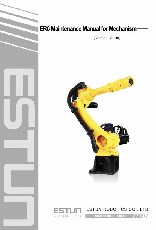
ER6 Maintenance Manual for Mechanism
(Version: V1.00)

Thank you for using the ESTUN Robot. We dedicate our energy to the
improvement in product quality.
The information in this document is subject to change without notice. Every effort has
been made in the preparation of this document to ensure accuracy of the contents,
but all statements, information, and recommendations in this document do not
constitute the warranty of any kind, express or implied.
It is solely the user’s responsibility to properly install and maintain any product.
ESTUN ROBOTICS manufactures its products to meet stringent specifications and
cannot assume responsibility for consequences arising from their misuse.
Copyright © ESTUN ROBOTICS CO., LTD. 2012. All rights reserved.
No part of this document may be reproduced or transmitted in any form or by any
means without prior written consent of ESTUN ROBOTICS CO., LTD.
ADD: 178, yanhu Road, Jiangning Development Zone, Nanjing
211102, P.R.China
TEL: 025-85097068 or 025-85097065
FAX: 025-85097089
WEB: www.estun-robotics.com
Email: [email protected]

Version History
NO. Date Version Description
1 2015-03-12 V1.00 Initial release.
ER6 Maintenance Manual for Mechanism
Contents
How to Use This Manual ............................................................................................ 1 Chapter 1 Safety Rules .............................................................................................. 2
1.1 Introduction ...................................................................................................... 2 1.2 General Safety Rules ...................................................................................... 2
1.2.1 Matters Need Attention in Robot System............................................................... 2 1.2.2 Risks and Hazards ................................................................................................ 2 1.2.3 Safety Action ......................................................................................................... 5 1.2.4 Emergency Stop .................................................................................................... 7
1.3 Robot Safety Rules .......................................................................................... 8 1.3.1 Safety Sign ............................................................................................................ 8 1.3.2 Potentially Fatal Danger ........................................................................................ 8 1.3.3 Potential Danger in Test ........................................................................................ 9 1.3.4 Electrical Hazard ................................................................................................... 9 1.3.5 Hazard in Reducer Box ....................................................................................... 10
Chapter 2 Installation and Commissioning ........................................................... 11 2.1 Structure of Mechanical System .................................................................... 11 2.2 Weight ............................................................................................................ 12 2.3 Specification .................................................................................................. 12 2.4 Working Space .............................................................................................. 13 2.5 Mechanical Brake .......................................................................................... 15 2.6 Mount ............................................................................................................. 16 2.7 Load Diagram ................................................................................................ 17 2.8 Flange Interface ............................................................................................. 18 2.9 J3-axis Mounting Interface ............................................................................ 18
Chapter 3 Calibration ............................................................................................... 19 3.1 Synopsis ........................................................................................................ 19 3.2 Tools .............................................................................................................. 19 3.3 Diagram ......................................................................................................... 20
3.3.1 J1-axis Calibration ............................................................................................... 20 3.3.2 J2-axis Calibration ............................................................................................... 21 3.3.3 J3-axis Calibration ............................................................................................... 21 3.3.4 J4-axis Calibration ............................................................................................... 22 3.3.5 J5-axis Calibration ............................................................................................... 22 3.3.6 J6-axis Calibration ............................................................................................... 23
Chapter 4 Maintenance ............................................................................................ 24 4.1 Routine Maintenance ..................................................................................... 24
4.1.1 Daily Maintenance ............................................................................................... 24 4.1.2 Quarterly Maintenance ........................................................................................ 24 4.1.3 Yearly Maintenance ............................................................................................. 25
4.2 Periodical Maintenance ................................................................................. 25 4.2.1 Azimuth for Lubricating ........................................................................................ 25 4.2.2 J1-, J2- and J3-axis Lubrication .......................................................................... 26

ER6 Maintenance Manual for Mechanism
4.2.3 J4-axis Lubrication .............................................................................................. 26 4.2.4 Small Arm (J6-axis) and Wrist Part Lubrication ................................................... 26
4.3 Robot Lubrication .......................................................................................... 27 4.3.1 Procedure ............................................................................................................ 27 4.3.2 Refill Openings of J1-axis and J2-axis ................................................................ 27 4.3.3 Oil Outlet of J2-axis ............................................................................................. 28 4.3.4 Refill Openings of J3-axis and J4-axis ................................................................ 28 4.3.5 Oil Outlets of J3-axis and J4-axis ........................................................................ 28 4.3.6 Refill Openings of Wrist ....................................................................................... 29 4.3.7 Oil Outlets of Wrist .............................................................................................. 29
4.4 Maintenance Area ......................................................................................... 29 Chapter 5 Troubleshooting ..................................................................................... 30
5.1 Synopsis ........................................................................................................ 30 5.2 FAQ ............................................................................................................... 30 5.3 Parts Weight .................................................................................................. 32 5.4 Parts Replacement ........................................................................................ 32
5.4.1 Replace Servomotor of J1-axis ........................................................................... 33 5.4.2 Replace Reducer of J1-axis ................................................................................ 34 5.4.3 Replace Servomotor of J2-axis ........................................................................... 35 5.4.4 Replace Reducer of J2-axis ................................................................................ 36 5.4.5 Replace Servomotor of J3-axis ........................................................................... 37 5.4.6 Replace Reducer of J3-axis ................................................................................ 38
Chapter 6 Scrapped Robot...................................................................................... 39 Chapter 7 The Referenced Standards .................................................................... 40 Appendix A Screw Tightening Torque ................................................................... 41

ER6 Maintenance Manual for Mechanism
1
How to Use This Manual
This manual shows you how to install, commission, calibrate and maintain ER6
Industrial Robot.
Chapter 1 introduces you to the safety rules.
Chapter 2 describes the mechanism structure, the feature, the component, and so
on, which helpful to your installation and commissioning.
Chapter 3 guides you to calibrate each axis.
Chapter 4 provides you to the routine maintenance.
Chapter 5 shows you how to resolve the troubles and the procedures of replacing
motor.
Chapter 6 explains the matters need attention for the scrapped robot.
Chapter 7 shows the referenced standards for this manual.
Appendix A lists a table of screw tightening torque.
NOTICE
This manual is intended for the manufacturer and the integrator, including the people who install,
commission, and maintain the robot. Whoever operates (installs, commissions, maintains) the
robot must be authorized and properly trained by our company. Furthermore, the person has had
to read this manual carefully for the operation.
ER6 Maintenance Manual for Mechanism
2
Chapter 1 Safety Rules
1.1 Introduction
The safety rules are divided into two parts:
The one part is the general safety rules, which are applied to many type of robot.
For details, see the section 1.2 General Safety Rules.
The other part is the robot safety rules, which are introduced the matters needing
attention for the operation and use. For details, see the section 1.3 Robot Safety
Rules.
1.2 General Safety Rules
1.2.1 Matters Need Attention in Robot System
The matters include neither how to install and operate the robot, nor the peripheral
equipment which may influence the robot safety. To keep the operator against the
danger, it is necessary to meet the local standards and rule of law for installing and
operating the robot.
Thanks for using our product, please master the local standards and rule of law for your
installation and operation. In general, it is necessary to install some appropriate safety
feature to safeguard the operator, and the Robot Instruction Book must be read carefully.
However, even though the operator absolutely follows all of the safety advices on the
Robot Instruction Book, ESTUN cannot keep the operator away from any danger.
1.2.2 Risks and Hazards
General
This section describes the potential dangers during your installation and operation.
To against the risks and hazards during your installation and operation:
- For the details about the matters needing attention of the installation, see
Chapter 2
- To convenient for emergency stop, the emergency stop switch must be
mounted at an easy-pressed place.
- The operator must ensure the safety measures are workable.
- The operator must be authorized and properly trained for the operation.
- The criterion of ESTUN robot for installing also must obey the local standards
and rule of law.
To against the risks of non-voltage:
- The safety area must be partitioned before installing the robot.
- Install the safeguard or the fence, in order to keep the operator out of the robot
working range. In addition, the danger signs for safety shall be on a proper
place, such as “No Visitor”, “High Voltage”, and so on.
- To avoid damaging the machine, nothing is allowed to hang above the robot.
ER6 Maintenance Manual for Mechanism
3
- The spring in the balancer may jump out and bring about the harm due to the
failure of other parts.
- Beware the falling parts when you split the robot.
- Beware the scald by the hot components in the electric cabinet.
- Prohibit treating the robot as a ladder when your maintenance. Also, do not
climb up the robot to avoid the falling.
- Beware the hot oil in the decelerator, its splashing may cause harm to human
body.
- Prohibit turning all robot axes with a spanner.
- Prohibit leaning against the electric cabinet, or casually pushing the buttons, in
case the robot brings some unexpected movements, which can cause
personal injury or equipment damage.
The matters needing attention for the integrator is as following:
- The integrator must ensure all the safety circuits are interlocked with the safety
circuit of external application.
- The integrator must ensure the safety circuit of emergency stop is interlocked
with the safety circuit of external application.
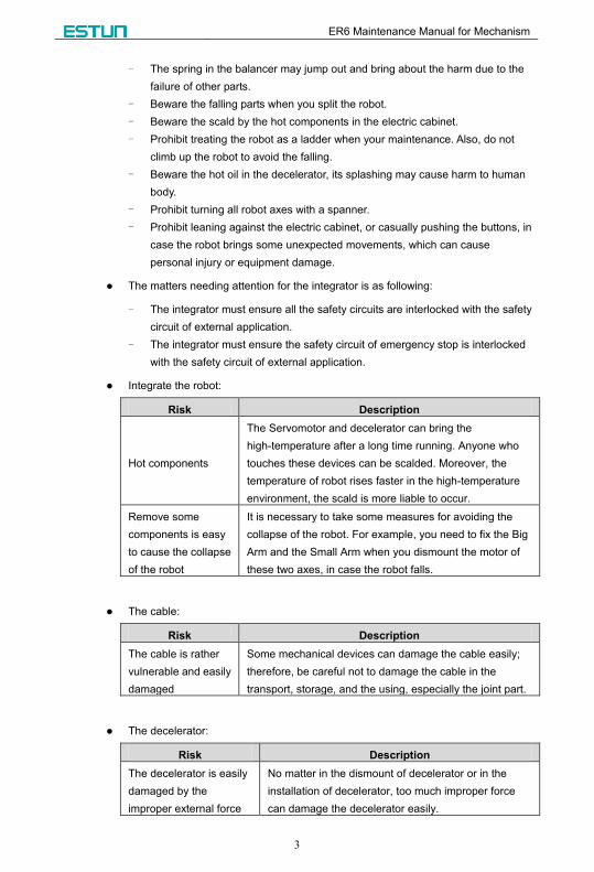
Integrate the robot:
Risk Description
Hot components
The Servomotor and decelerator can bring the
high-temperature after a long time running. Anyone who
touches these devices can be scalded. Moreover, the
temperature of robot rises faster in the high-temperature
environment, the scald is more liable to occur.
Remove some
components is easy
to cause the collapse
of the robot
It is necessary to take some measures for avoiding the
collapse of the robot. For example, you need to fix the Big
Arm and the Small Arm when you dismount the motor of
these two axes, in case the robot falls.
The cable:
Risk Description
The cable is rather
vulnerable and easily
damaged
Some mechanical devices can damage the cable easily;
therefore, be careful not to damage the cable in the
transport, storage, and the using, especially the joint part.
The decelerator:
Risk Description
The decelerator is easily
damaged by the
improper external force
No matter in the dismount of decelerator or in the
installation of decelerator, too much improper force
can damage the decelerator easily.
ER6 Maintenance Manual for Mechanism
4
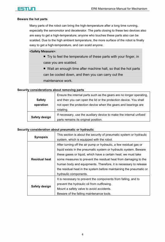
Beware the hot parts
Many parts of the robot can bring the high-temperature after a long time running,
especially the servomotor and decelerator. The parts closing to these two devices also
are easy to get a high-temperature; anyone who touches these parts also can be
scalded. Due to the high ambient temperature, the more surface of the robot is finally
easy to get a high-temperature, and can scald anyone.
<Safety Measure>:
■ Try to feel the temperature of these parts with your finger, in
case you are scalded.
■ Wait an enough time after machine halt, so that the hot parts
can be cooled down, and then you can carry out the
maintenance work.
Security considerations about removing parts
Safety
operation
Ensure the internal parts such as the gears are no longer operating,
and then you can open the lid or the protection device. You shall
not open the protection device when the gears and bearings are
rotating.
Safety design If necessary, use the auxiliary device to make the internal unfixed
parts remains its original position.
Security consideration about pneumatic or hydraulic
Synopsis This section is about the security of pneumatic system or hydraulic
system, which is equipped with the robot.
Residual heat
After turning off the air pump or hydraulic, a few residual gas or
liquid exists in the pneumatic system or hydraulic system. Beware
these gases or liquid, which have a certain heat; we must take
some measures to prevent the residual heat from damaging to the
human body and equipments. Therefore, it is necessary to release
the residual heat in the system before maintaining the pneumatic or
hydraulic components.
Safety design
It is necessary to prevent the components from falling, and to
prevent the hydraulic oil from outflowing.
Mount a safety valve to avoid accidents.
Beware of the falling maintenance tools.
ER6 Maintenance Manual for Mechanism
5
The risk of operation
Synopsis
The industrial robot is a flexible system, which can be applied to
may industrial fields. All work must be operated by a professional
personnel, and abide by certain safety standards. Always be
careful of the operation.
Qualified
operators
The professional operators, who are familiar with the whole
system and clear the existent risks in every subsystems, can
operate the industrial robot.
Risk of exception Take seriously care when the working procedure is abnormal.
The risk of electric
Synopsis
The power supply need be opened in many cases of fault
diagnosis, but it must be shut when the maintenance or repair
is carried, moreover, you should cut off the other power supply
connection.
The main power supply of robot need be mounted out the
range of working. In this way, even if the robot is out of control,
the operator can stop the robot out the range of working.
Risk of operators
The operator must pay attention to the high voltage:
The power line of servo drive.
The power line connects the fixture with other the other
devices.
The electrical hazard from the end effector, external equipment,
and so on, is that: after the robot is turned off, the peripherals
may still running. Thus, the damaged power line or power cable
of peripherals also can harm the person.
Risk of exception Take seriously care when the working procedure is abnormal.
1.2.3 Safety Action
Safety Measure
Synopsis
It is necessary to place the fence and safety signs round the
working space of robot, to ensure the robot can work without
accident, and it may delimit a no-go area to prevent the robot
from injuring people.
Safety measures
To set up the safety measures, it is necessary to consider the
workpieces, which is held by the robot, can fall down and injure
people.
Fire Danger
It is necessary to place a carbon dioxide bottle in the work field, in case
the robot system is fired.

ER6 Maintenance Manual for Mechanism
6
Remove the robot arm in an emergency
Meaning
In the case of an emergency, any one of robot arm needs to
dismantle, if the robot arm has nipped the operator. For details
about the procedure of dismantling, see Chapter 4 Maintenance.
The robot arm can be removed manually, but the robot Big Arm
need use a crane or other small device to remove.
Secondary
damage
Before releasing the joint and braking, you must fix the robot arm, in
case the robot arm under the gravity action causes a secondary
damage to the victims.
Brake detection
Why to detect In general, the brake can be worn in the normal operation.
Therefore, the brake detection is necessary.
Detection
procedure
Step 1 Move each joint to a position, where the joint can bear the
maximum load.
Step 2 Shutdown the robot and brake.
Step 3 Marking every joints of robot.
Step 4 Wait for a moment, and examine whether any joint moves.
Use the teach pendant in security
Press the button Mot on the teach pendant to turn-on or turn-off the
servomotor.
Rules
In order to use the teach pendant in security, you need to obey the
following rules:
The enable button cannot failure at any time.
Turn off the enable button in time when programming or testing.
The operator, who carries out the teaching, must bring the teach
pendant and walk into the working space of robot, in case anyone
unwittingly handles the robot.
The teach pendant must be kept away from the working space of
robot, in case the robot can bump it and cause any abnormal action.
Enable Turn off the enable button in time, when you intermit the operation,
programming or testing.
ER6 Maintenance Manual for Mechanism
7
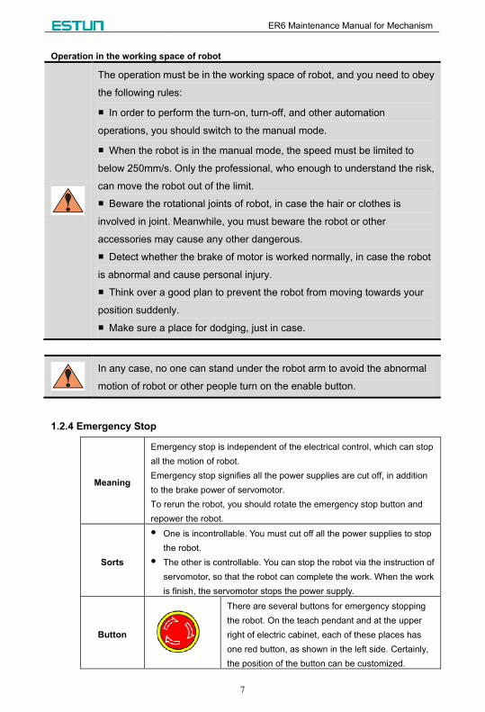
Operation in the working space of robot
The operation must be in the working space of robot, and you need to obey
the following rules:
■ In order to perform the turn-on, turn-off, and other automation
operations, you should switch to the manual mode.
■ When the robot is in the manual mode, the speed must be limited to
below 250mm/s. Only the professional, who enough to understand the risk,
can move the robot out of the limit.
■ Beware the rotational joints of robot, in case the hair or clothes is
involved in joint. Meanwhile, you must beware the robot or other
accessories may cause any other dangerous.
■ Detect whether the brake of motor is worked normally, in case the robot
is abnormal and cause personal injury.
■ Think over a good plan to prevent the robot from moving towards your
position suddenly.
■ Make sure a place for dodging, just in case.
In any case, no one can stand under the robot arm to avoid the abnormal
motion of robot or other people turn on the enable button.
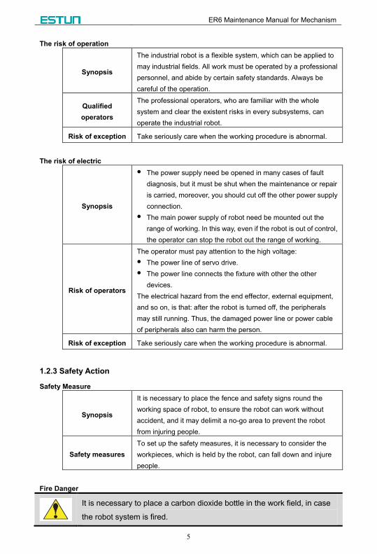
1.2.4 Emergency Stop
Meaning
Emergency stop is independent of the electrical control, which can stop
all the motion of robot.
Emergency stop signifies all the power supplies are cut off, in addition
to the brake power of servomotor.
To rerun the robot, you should rotate the emergency stop button and
repower the robot.
Sorts
One is incontrollable. You must cut off all the power supplies to stop
the robot.
The other is controllable. You can stop the robot via the instruction of
servomotor, so that the robot can complete the work. When the work
is finish, the servomotor stops the power supply.
Button
There are several buttons for emergency stopping
the robot. On the teach pendant and at the upper
right of electric cabinet, each of these places has
one red button, as shown in the left side. Certainly,
the position of the button can be customized.
ER6 Maintenance Manual for Mechanism
8
Emergency Stop is just used for stopping the robot in the case of an
emergency. That is to say, it cannot be used in the normal stop.
1.3 Robot Safety Rules
Before your operation (install, commission, maintenance, repair), you must read and
master this manual and other ancillary documents.
1.3.1 Safety Sign
The following symbols with an adjoining safety advice or notice are used in this manual.
You have to read the safety advices carefully and obey them strictly!
Danger symbol
If you do not obey the safety advice adjoining this symbol, there is danger
to life and health of individuals!
Caution symbol
If you do not obey the safety advice adjoining this symbol, there is
obvious hazard to individuals!
Must do
You must obey the safety advice adjoining this symbol.
Forbiddance
You must obey the safety advice adjoining this symbol.
Note or pointer
This symbol indicates information that contributes to better understanding.
1.3.2 Potentially Fatal Danger
Synopsis
Any of working robot has a potentially fatal danger. The working robot
may appear unpredictable motions, all these motions contain much
powerful energy, which can destroy the equipment or seriously injure
the operator.
Avoid
method
Before preparing to operate the robot, you’d better detect all the
securities, including the brake, the fence, and the indicator light.
Avoid
measure
Before starting up the robot, make sure that nobody is in the working
space of robot.

ER6 Maintenance Manual for Mechanism
9
1.3.3 Potential Danger in Test
Synopsis
It is necessary to dismount the robot for the repair and maintenance.
When the repair and maintenance is finished, some risks need to be
considered for your first testing.
Measures
Follow the below procedures for your first testing:
Step 1 Clear up all the tools and materials in the working space of
robot, including the robot body.
Step 2 Mount all safety measures.
Step 3 Make sure all the people are out the working space of robot.
Step 4 Especially notice the work of component had been repaired or
been maintained in your testing.
You must notice whether there is any interferential dangers when the
robot is processing the program.
1.3.4 Electrical Hazard
Synopsis Electric cabinet is the Centre of the robot. Any wrong operation might lead to
electric shock or malfunction of robot, thus harming to personal or equipment.
Safety
measures
Never against the electric cabinet or other control cabinet, and never casually
push the buttons. Otherwise, the robot might bring some unexpected
movements, which can cause personal injury or equipment damage.
In course of operation, never allow the non-work personnel to touch the electric
cabinet. Otherwise, the robot might bring some unexpected movements, which
can cause personal injury or equipment damage.
Some safety measures must be taken when electric cabinet wires and runs the
wire to the robot and peripheral equipment. For example, cover the pipes,
wires or cables with the slot or the shell, in case the people or forklift treads on
them. Moreover, the operator and other people might be stumbled by the open
wires, cables or the pipes. As a result, the robot might bring some unexpected
movements, which can cause personal injury or equipment damage.
When you install a device on the robot, the power supplies of the electric
cabinet and the device must be cut off (OFF) and be locked, and then hang a
caution sign. If you power on in your installation, it might cause the danger of
electric shock, or the robot might bring some unexpected movements, which
can cause personal injury or equipment damage.
Before your operation, you should press emergency stop buttons, which is on
the teach pendant or the upper right of electric cabinet, in order to check
whether the indicator of Servo Ready is not light, and make sure the power of
the indicator is turnoff.
<Note>: For details about the electrical hazard, see <ER Series Maintenance Manual for
Electric>.
ER6 Maintenance Manual for Mechanism
10
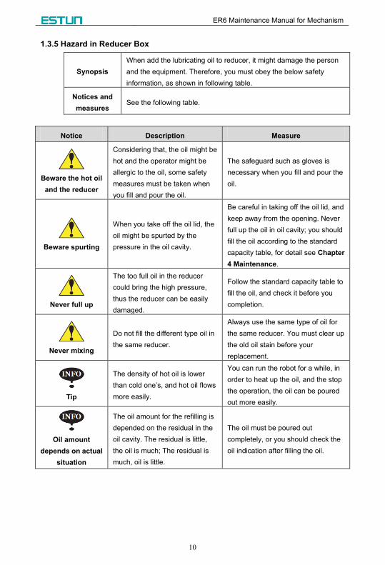
1.3.5 Hazard in Reducer Box
Synopsis
When add the lubricating oil to reducer, it might damage the person
and the equipment. Therefore, you must obey the below safety
information, as shown in following table.
Notices and
measures See the following table.
Notice Description Measure
Beware the hot oil
and the reducer
Considering that, the oil might be
hot and the operator might be
allergic to the oil, some safety
measures must be taken when
you fill and pour the oil.
The safeguard such as gloves is
necessary when you fill and pour the
oil.
Beware spurting
When you take off the oil lid, the
oil might be spurted by the
pressure in the oil cavity.
Be careful in taking off the oil lid, and
keep away from the opening. Never
full up the oil in oil cavity; you should
fill the oil according to the standard
capacity table, for detail see Chapter
4 Maintenance.
Never full up
The too full oil in the reducer
could bring the high pressure,
thus the reducer can be easily
damaged.
Follow the standard capacity table to
fill the oil, and check it before you
completion.
Never mixing
Do not fill the different type oil in
the same reducer.
Always use the same type of oil for
the same reducer. You must clear up
the old oil stain before your
replacement.
Tip
The density of hot oil is lower
than cold one’s, and hot oil flows
more easily.
You can run the robot for a while, in
order to heat up the oil, and the stop
the operation, the oil can be poured
out more easily.
Oil amount
depends on actual
situation
The oil amount for the refilling is
depended on the residual in the
oil cavity. The residual is little,
the oil is much; The residual is
much, oil is little.
The oil must be poured out
completely, or you should check the
oil indication after filling the oil.
ER6 Maintenance Manual for Mechanism
11
Chapter 2 Installation and Commissioning
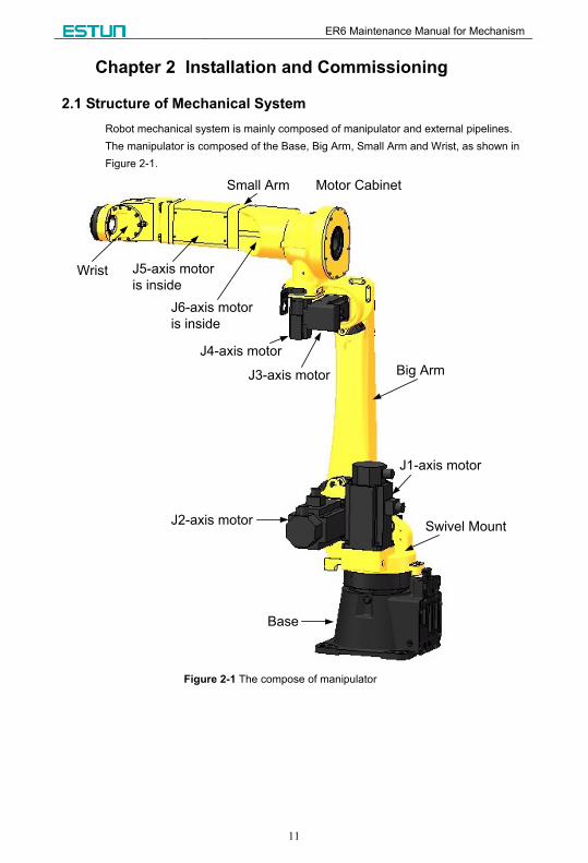
2.1 Structure of Mechanical System
Robot mechanical system is mainly composed of manipulator and external pipelines.
The manipulator is composed of the Base, Big Arm, Small Arm and Wrist, as shown in
Figure 2-1.
Wrist J5-axis motor
is inside
J6-axis motor
is inside
Motor CabinetSmall Arm
J3-axis motor
J4-axis motor
Big Arm
J2-axis motor
J1-axis motor
Base
Swivel Mount
Figure 2-1 The compose of manipulator
ER6 Maintenance Manual for Mechanism
12
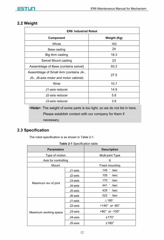
2.2 Weight
ER6 Industrial Robot
Component Weight (Kg)
Whole 163
Base casting 24
Big Arm casting 18.3
Swivel Mount casting 23
Assemblage of Base (contains swivel) 93.2
Assemblage of Small Arm (contains J4-,
J5-, J6-axis motor and motor cabinet) 27.5
Wrist 10.7
J1-axis reducer 14.9
J2-axis reducer 5.8
J3-axis reducer 3.8
<Note>: The weight of some parts is too light, so we do not list in here.
Please establish contact with our company for them if
necessary.
2.3 Specification
The robot specification is as shown in Table 2-1.
Table 2-1 Specification table
Parameters Description
Type of motion Multi-joint Type
Axis for controlling 6
Mount Fixed mounting
Maximum rev of joint
J1-axis 145 °/sec
J2-axis 105 °/sec
J3-axis 170 °/sec
J4-axis 441 °/sec
J5-axis 435 °/sec
J6-axis 522 °/sec
Maximum working space
J1-axis ±180°
J2-axis +140° or -60°
J3-axis +80° or -155°
J4-axis ±170°
J5-axis ±180°

ER6 Maintenance Manual for Mechanism
13
Parameters Description
J6-axis ±360°
Maximum radius of motion 1.6m
Limiting load of wrist 6Kg
Additional load of the third axis 10Kg
Repeated positioning precision ±0.08mm
2.4 Working Space
As shown in Figure 2-2, you can know the working space of the ER6 industrial robot.
Figure 2-2 Diagram of working space
Type Range of each axis
J1-axis J2-axis J3-axis J4-axis J5-axis J6-axis
ER6 ±180° -60° to +140° -155° to +80° ±170° ±180° ±360°
ER6 Maintenance Manual for Mechanism
14
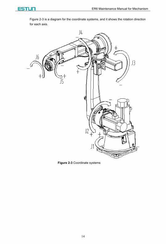
Figure 2-3 is a diagram for the coordinate systems, and it shows the rotation direction
for each axis.
Figure 2-3 Coordinate systems
ER6 Maintenance Manual for Mechanism
15
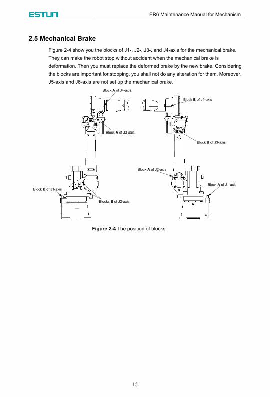
2.5 Mechanical Brake
Figure 2-4 show you the blocks of J1-, J2-, J3-, and J4-axis for the mechanical brake.
They can make the robot stop without accident when the mechanical brake is
deformation. Then you must replace the deformed brake by the new brake. Considering
the blocks are important for stopping, you shall not do any alteration for them. Moreover,
J5-axis and J6-axis are not set up the mechanical brake.
Block A of J4-axis
Block A of J3-axis
Blocks B of J2-axis
Block B of J1-axis
Block B of J4-axis
Block B of J3-axis
Block A of J2-axis
Block A of J1-axis
Figure 2-4 The position of blocks
ER6 Maintenance Manual for Mechanism
16
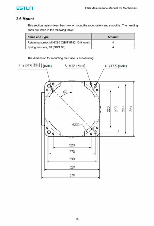
2.6 Mount
This section mainly describes how to mount the robot safely and smoothly. The needing
parts are listed in the following table:
Name and Type Amount
Retaining screw, M16X80 (GB/T 5782 10.9 level) 4
Spring washers, 16 (GB/T 93) 4
The dimension for mounting the Base is as following:

ER6 Maintenance Manual for Mechanism
17
2.7 Load Diagram
Any load on the robot has to follow the load diagram, in case the robot vibrating and
unsafe run, motor overloading, reducer overloading and structure overloading. The ER6
load diagram is as shown in Figure 2-5, which the unit is mm.
Figure 2-5 ER6 load diagram
<Note>: The load must be in conformity with ER6 load diagram. The
mass of the load and their own inertia must be confirmed in
various cases. The overloading would lead to the motor
overloading, reducer overloading, and shorten the service life of
the robot. Furthermore, it can damage the robot in a bad case.
ER6 Maintenance Manual for Mechanism
18
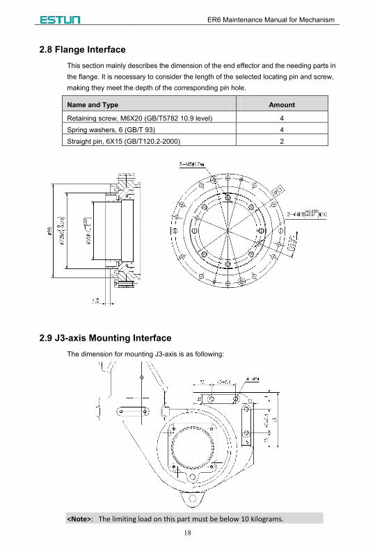
2.8 Flange Interface
This section mainly describes the dimension of the end effector and the needing parts in
the flange. It is necessary to consider the length of the selected locating pin and screw,
making they meet the depth of the corresponding pin hole.
Name and Type Amount
Retaining screw, M6X20 (GB/T5782 10.9 level) 4
Spring washers, 6 (GB/T 93) 4
Straight pin, 6X15 (GB/T120.2-2000) 2
2.9 J3-axis Mounting Interface
The dimension for mounting J3-axis is as following:
<Note>: The limiting load on this part must be below 10 kilograms.
ER6 Maintenance Manual for Mechanism
19
Chapter 3 Calibration
3.1 Synopsis
Zero Calibration is an operation, which specifies the angle of each joint for the
corresponding pulses. By this token, the purpose of zero calibration is that to obtain the
corresponding pulses for the zero position.
Zero Calibration has been completed before leaving the factory. It is not necessary to
perform the calibration in routine work, but the following case:
<1> Replace the motor;
<2> Replace the encoder;
<3> Replace the reducer;
<4> Replace the cable;
<5> The battery for the backup of pluses in the machine has been run out.
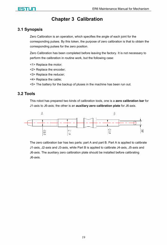
3.2 Tools
This robot has prepared two kinds of calibration tools, one is a zero calibration bar for
J1-axis to J6-axis; the other is an auxiliary zero calibration plate for J6-axis.
The zero calibration bar has two parts: part A and part B. Part A is applied to calibrate
J1-axis, J2-axis and J3-axis, while Part B is applied to calibrate J4-axis, J5-axis and
J6-axis. The auxiliary zero calibration plate should be installed before calibrating
J6-axis.

ER6 Maintenance Manual for Mechanism
20
3.3 Diagram
Use the calibration bar to calibrate the zero position of each axis, and in the following we
give the calibration diagram to convenient for your operation.
3.3.1 J1-axis Calibration
Figure 3-1 The diagram of calibrating J1-axis
As shown in Figure 3-1, the Base and the Swivel Mount each has one pin hole.
Following the below procedure for the calibration:
1 Use the teach pendant to rotate the J1-axis, and align the two pin holes are in an
upright line by your eye-measurement.
2 Insert the calibration bar into the J1-axis pin hole (the upper one).
3 Jog the J1-axis to make the calibration bar also can be inserted into the lower pin
hole, what means the zero position is current position for the J1-axis.
4 Set the zero position in the teach pendant.
So much for that, the J1-axis calibration is done. You can reference to the above
procedure for the others calibration, and the following diagram would helpful to your
calibration.
ER6 Maintenance Manual for Mechanism
21
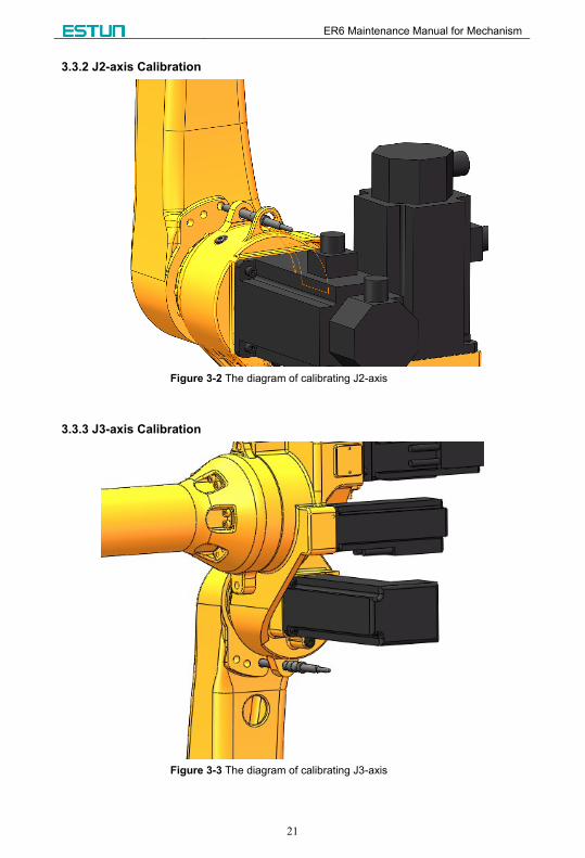
3.3.2 J2-axis Calibration
Figure 3-2 The diagram of calibrating J2-axis
3.3.3 J3-axis Calibration
Figure 3-3 The diagram of calibrating J3-axis

ER6 Maintenance Manual for Mechanism
22
3.3.4 J4-axis Calibration
Figure 3-4 The diagram of calibrating J4-axis
3.3.5 J5-axis Calibration
Figure 3-5 The diagram of calibrating J5-axis

ER6 Maintenance Manual for Mechanism
23
3.3.6 J6-axis Calibration
Figure 3-6 The diagram of calibrating J6-axis
As shown in Figure 3-6, you should use the pivot-pins (Φ6) to hold the auxiliary zero
calibration plate on the robot, and then calibrate J6-axis with the zero calibration bar.
When you align the pin holes and try to insert the calibration bar into them,
the speed of jogging the robot must be reduced to 5%. In addition, prohibit
any operation when the calibration bar has been inserted into the pin holes,
in case any unexpected accident happens.

ER6 Maintenance Manual for Mechanism
24
Chapter 4 Maintenance
4.1 Routine Maintenance
To keep the high performance of robot, follow this section to carry out the maintenance.
4.1.1 Daily Maintenance
Table 4-1 The daily maintenance list
No. Item How to do
1 Leak test Check whether the components have the leak, e.g. F.R.L Unit,
tracheas, and joints.
2 Abnormal noise test Check whether each drive has the abnormal sound noise.
3 Interference test Check whether each drive runs smoothly without any
vibration.
4 Ventilation test Check whether the ventilator after the electric cabinet runs
smoothly.
5 Peripheral corrugated
pipe test
Check whether all the corrugated pipes are complete, worn or
rusted.
6 Peripheral circuit test Check whether the peripheral circuit is normal, damaged or
the button is in good condition.
4.1.2 Quarterly Maintenance
Table 4-2 Quarterly maintenance list
No. Item How to do
1 Cable of control
unit Check whether the cable of teach pendant is damaged or twisted.
2 Ventilation of
control unit
If the ventilation unit is dirty, you should cut off the power supply and
cleanup it.
3 Cable of machinery
Check whether machinery plug is damaged, bent, or abnormal, and
check whether the connector assembly is in good connection.
When the angle of J4-axis is 0
degree, check whether the cable
in the motor cabinet is
surrounded by four rings, and
whether the nylon cable ties at
the ends of the cable are
fastened, as shown in the right
figure.
4 Clean and check
each component Clean each component and check whether they have any exception.
5 Tighten screws Tighten the screws of the end effector and external important screws.

ER6 Maintenance Manual for Mechanism
25
4.1.3 Yearly Maintenance
Table 4-3 The yearly maintenance list
No. Item How to do
1 Replace batteries Replace the batteries in the mechanical unit.
2 Replace the lubricating oil
of reducer and gearbox Replace the lubricating oil follow the lubricating requirement.
4.2 Periodical Maintenance
This section can help you for lubricating the device. Every three years or the
accumulated running time is over 11,520 hours, you should replace the lubricating
grease for J1-axis, J2axis, and J3-axis, and replace the lubricating oil for the gearbox of
J4-axis, J5-axis and J6-axis. The description of lubricant is as shown in Table 4-4.
Table 4-4 Lubricating Replacement
Robot Part Capacity Lubricant Name
ER6
J1-axis reducer 1000 milliliter
MolywhiteRE No.00 J2-axis reducer 1050 milliliter
J3-axis reducer 260 milliliter
J4-axis gearbox 750 milliliter
ENEOS BONNOC AX68 Small Arm (J6-axis) gearbox 343 milliliter
Wrist part 358 milliliter
4.2.1 Azimuth for Lubricating
As shown in Table 4-5, it lists the recommended azimuth for your lubricating.
Table 4-5 Azimuth for lubricating
Part Azimuth
J1 J2 J3 J4 J5 J6
J1-axis reducer
Any
angle
Any
angle Any
angle Any
angle
Any
angle
Any
angle J2-axis reducer 0°
J3-axis reducer 0° 0°
J4-axis gearbox
Any
angle
-90° Any
angle
Any
angle
Any
angle
Small Arm (J6-axis)
gearbox 11° 0° 0° 0°
Wrist part

ER6 Maintenance Manual for Mechanism
26
4.2.2 J1-, J2- and J3-axis Lubrication
1 Move the robot to the recommended azimuth with the teach pendant, as shown in
Table 4-5.
2 Cut off the power supply.
3 Remove the plug screw from the oil outlet.
4 Remove the plug screw from the refill opening.
5 Fill the new lubricating oil until the oil overflows from the refill opening.
6 Mount the plug screw on the refill opening.
4.2.3 J4-axis Lubrication
1 Move the robot to the recommended azimuth with the teach pendant, as shown in
Table 4-5.
2 Cut off the power supply.
3 Put an oil bottle for recycling underneath the oil outlet.
4 Remove the plug screw from the oil outlet.
5 Pour out the old oil, and then mount the plug screw.
6 Open the refill opening and breather hole, and fill the new lubricating oil according
to the specify capacity.
7 Mount the plug screw on the refill opening.
4.2.4 Small Arm (J6-axis) and Wrist Part Lubrication
1 Move the robot to the recommended azimuth with the teach pendant, as shown in
Table 4-5.
2 Cut off the power supply.
3 Put an oil bottle for recycling underneath the oil outlet.
4 Remove the plug screw from the oil outlet, which is under the wrist cavity.
5 Pour out the old oil, and then mount the plug screw.
6 Fill the new lubricating oil according to the specify capacity.
7 Mount the plug screw on the refill opening.
If you fail to lubricate correctly, the pressure in the oil cavity may be increased suddenly,
which can damage the sealing part, leading to the lubricating oil leaked and abnormal
operation. Therefore, please obey the following precautions:
Before lubricating operation, remove the oil outlet (that is to say, remove the plug
screw from the oil outlet).
Fill the lubricating oil as slowly as possible. Never rush.
As long as possible, avoid using compressed gas pump, which is driven by the
industrial air supply.
Only use the specified lubricating oil. The unspecified lubricating oil can lead to
reducer damaged or others failure.

ER6 Maintenance Manual for Mechanism
27
When complete the lubrication, make sure no lubricating oil leaked at the oil outlet,
and no pressure in the oil cavity, and then seal all the oil holes.
To avoid the accidents caused by slip, clean up the redundant oil on the ground and
the robot.
4.3 Robot Lubrication
4.3.1 Procedure
Obey the Safety Rules in Chapter 1 to know the hazard in lubricating the
reducer.
The normative procedure of lubricating the oil is as following:
1 Loosen the plug screws on the refill opening and breather hole. (the breather hole is
used for ventilating)
2 Screw the filler nozzle on the refill opening.
3 Fill the specified oil with the oil gun.
4 Loosen the filler nozzle and tighten the plug screws after the filling.
4.3.2 Refill Openings of J1-axis and J2-axis
Oil outlet
of J1-axis
Refill opening
of J1-axis
Refill opening
of J2-axis
Figure 4-1 Refill openings of J1-axis and J2-axis

ER6 Maintenance Manual for Mechanism
28
4.3.3 Oil Outlet of J2-axis
Oil outlet
of J2-axis
Figure 4-2 Oil Outlet of J2-axis
4.3.4 Refill Openings of J3-axis and J4-axis
Refilling opening of J4-axis
Refilling opening of J3-axisBreather hole of J4-axis
Figure 4-3 Refill openings of J3-axis and J4-axis
4.3.5 Oil Outlets of J3-axis and J4-axis
Oil outlet of J4-axis
Oil outlet of J3-axis
Figure 4-4 Oil outlets of J3-axis and J4-axis
ER6 Maintenance Manual for Mechanism
29
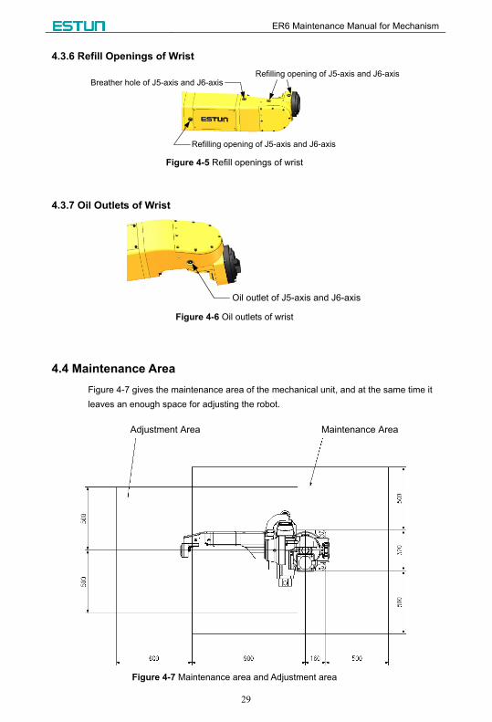
4.3.6 Refill Openings of Wrist
Breather hole of J5-axis and J6-axis
Refilling opening of J5-axis and J6-axis
Refilling opening of J5-axis and J6-axis
Figure 4-5 Refill openings of wrist
4.3.7 Oil Outlets of Wrist
Oil outlet of J5-axis and J6-axis
Figure 4-6 Oil outlets of wrist
4.4 Maintenance Area
Figure 4-7 gives the maintenance area of the mechanical unit, and at the same time it
leaves an enough space for adjusting the robot.
Maintenance AreaAdjustment Area
Figure 4-7 Maintenance area and Adjustment area
ER6 Maintenance Manual for Mechanism
30
Chapter 5 Troubleshooting
5.1 Synopsis
About this chapter
This chapter mainly lists the several kinds of frequent trouble, their causes and their
solution. Meanwhile, section 5.4 guides you how to replace the parts.
Necessary tools
Travelling crane, Forklift truck, Inner hexagon spanner, Monkey wrench, and the special
tool for assembling and disassembling the bearing.
Safety information
For the main security considerations, see the section 1.2 General Safety Rules and 1.3
Robot Safety Rules. Make sure you have read all the security considerations through.
Never do any maintenance before cutting off the power supply!
5.2 FAQ
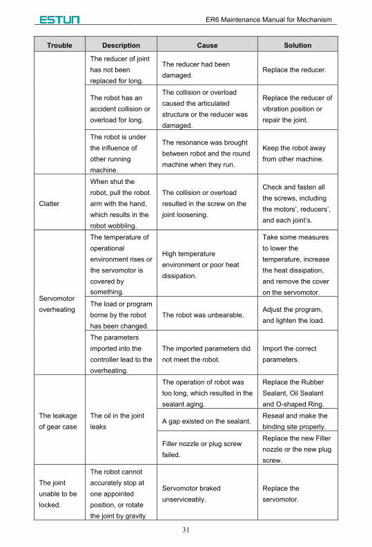
Trouble Description Cause Solution
Vibration
noise
The connection
between the Base
and the ground is
unstable.
Operating the robot could
bring the frequent vibration,
making the connection
between the Base and the
ground unstable.
Refasten the
connection between
the Base and the
ground.
The connection
between two joints
is unstable.
The screw between two joints
did not meet the
pre-tightening force, or the
screw did not use any
measure against the
unstableness, e.g. spring
washer, and thread sealant.
Remount the screws,
and refasten them.
The vibration is
obvious if the robot
is over a certain
speed.
The hardware of the robot
was strenuous to run the
program.
Readjust the program
of robot.
The vibration is
obvious when the
robot moves a
particular position.
The load of robot was too
much.
Lighten the load of
robot.
ER6 Maintenance Manual for Mechanism
31
Trouble Description Cause Solution
The reducer of joint
has not been
replaced for long.
The reducer had been
damaged. Replace the reducer.
The robot has an
accident collision or
overload for long.
The collision or overload
caused the articulated
structure or the reducer was
damaged.
Replace the reducer of
vibration position or
repair the joint.
The robot is under
the influence of
other running
machine.
The resonance was brought
between robot and the round
machine when they run.
Keep the robot away
from other machine.
Clatter
When shut the
robot, pull the robot
arm with the hand,
which results in the
robot wobbling.
The collision or overload
resulted in the screw on the
joint loosening.
Check and fasten all
the screws, including
the motors’, reducers’,
and each joint’s.
Servomotor
overheating
The temperature of
operational
environment rises or
the servomotor is
covered by
something.
High temperature
environment or poor heat
dissipation.
Take some measures
to lower the
temperature, increase
the heat dissipation,
and remove the cover
on the servomotor.
The load or program
borne by the robot
has been changed.
The robot was unbearable. Adjust the program,
and lighten the load.
The parameters
imported into the
controller lead to the
overheating.
The imported parameters did
not meet the robot.
Import the correct
parameters.
The leakage
of gear case
The oil in the joint
leaks
The operation of robot was
too long, which resulted in the
sealant aging.
Replace the Rubber
Sealant, Oil Sealant
and O-shaped Ring.
A gap existed on the sealant. Reseal and make the
binding site properly.
Filler nozzle or plug screw
failed.
Replace the new Filler
nozzle or the new plug
screw.
The joint
unable to be
locked.
The robot cannot
accurately stop at
one appointed
position, or rotate
the joint by gravity
Servomotor braked
unserviceably.
Replace the
servomotor.

ER6 Maintenance Manual for Mechanism
32
5.3 Parts Weight
Lift parts of robot in the repairing is necessary. Before lifting, you must
confirm the load range of lifting tool. For details about the weight of the
parts, see the section 2.2 Weight.
5.4 Parts Replacement
This section describes how to replace the servomotors and the reducers of J1-, J2-, and
J3-axis, and how to replace the gearboxes of J4-, J5-, and J6-axis. If you dismount the
robot by yourself, perhaps your operation should reduce the precision of robot. We
suggest you to contact our company in time for the problems of J4-, J5, and J6-axis.
You’d better to preserve the dismantled parts well and clean up them
before remounting. If you find any part is damaged, you must replace it in
time.
When dismantle the parts of robot, the other parts could lose the support,
and bring unexpected movement, then it likely to endanger the person or
equipment. Therefore, a professional must carry out the dismantlement.
ER6 Maintenance Manual for Mechanism
33
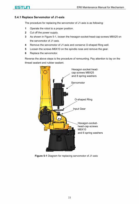
5.4.1 Replace Servomotor of J1-axis
The procedure for replacing the servomotor of J1-axis is as following:
1 Operate the robot to a proper position.
2 Cut off the power supply.
3 As shown in Figure 5-1, loosen the hexagon-socket-head-cap-screws M8X25 on
the servomotor of J1-axis.
4 Remove the servomotor of J1-axis and conserve O-shaped Ring well.
5 Loosen the screws M6X10 on the spindle nose and remove the gear.
6 Replace the servomotor.
Reverse the above steps is the procedure of remounting. Pay attention to lay on the
thread sealant and rubber sealant.
Hexagon-socket-head-
cap-screws M8X25
and 8 spring washers
Servomotor
O-shaped Ring
Input Gear
Hexagon-socket-
head-cap-screws
M6X10
and 6 spring washers
Figure 5-1 Diagram for replacing servomotor of J1-axis

ER6 Maintenance Manual for Mechanism
34
5.4.2 Replace Reducer of J1-axis
The procedure for replacing the reducer of J1-axis is as following:
1 Operate the robot to a proper position, where can be easy to lift the above parts of
the Swivel Mount.
2 Cut off the power supply, and hoist the robot to a certain height.
3 Pull out the plug of the servomotor.
4 As shown in Figure 5-2, loosen the M4X8 screws and remove the back plane.
5 Pad the back plane, and loosen the M4X8 screws.
The reducer of J1-axis can be separated from the back plane.
6 Loosen the M8X80 screws.
The reducer can be separated from the Swivel Mount.
7 Remove the threading pipe, O-shaped Ring, bearing and oil sealant, and then you
can replace the reducer.
Reverse the above steps is the procedure of remounting. Pay attention to lay on the
thread sealant and rubber sealant.
Oil Sealant
Bearing
O-shaped Ring
Threading Pipe, O-shaped Ring,
Hexagon-socket-head-cap-screw
M4X8 and Spring Washer
Hexagon-socket-head-cap-screw
M8X80 and Spring Washer
Hexagon-socket-head-cap-screw
M10X35 and Spring Washer Back Plane, Hexagon-
socket-head-cap-screw
M4X8 and Spring Washer
Figure 5-2 Diagram for replacing reducer of J1-axis
ER6 Maintenance Manual for Mechanism
35
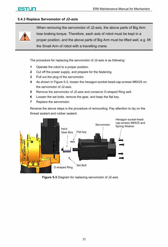
5.4.3 Replace Servomotor of J2-axis
When removing the servomotor of J2-axis, the above parts of Big Arm
lose braking torque. Therefore, each axis of robot must be kept in a
proper position, and the above parts of Big Arm must be lifted well, e.g. lift
the Small Arm of robot with a travelling crane.
The procedure for replacing the servomotor of J2-axis is as following:
1 Operate the robot to a proper position.
2 Cut off the power supply, and prepare for the fastening.
3 Pull out the plug of the servomotor.
4 As shown in Figure 5-3, loosen the hexagon-socket-head-cap-screws M8X25 on
the servomotor of J2-axis.
5 Remove the servomotor of J2-axis and conserve O-shaped Ring well.
6 Loosen the set bolts, remove the gear, and keep the flat key.
7 Replace the servomotor.
Reverse the above steps is the procedure of remounting. Pay attention to lay on the
thread sealant and rubber sealant.
Flat key
Set BoltO-shaped Ring
Input
Gear Box
Servomotor
Hexagon-socket-head-
cap-screws M8X25 and
Spring Washer
Figure 5-3 Diagram for replacing servomotor of J2-axis

ER6 Maintenance Manual for Mechanism
36
5.4.4 Replace Reducer of J2-axis
The procedure for replacing the reducer of J2-axis is as following:
1 Operate the robot to a proper position, where can be easy to lift the above parts of
the Big Arm.
2 Cut off the power supply, and hoist the Big Arm well.
3 Remove the servomotor of J2-axis, for details see the above section.
4 Remove the locating piece of Big Arm, and loosen the
hexagon-socket-head-cap-screws M8X30.
5 Remove the above parts of Big Arm with the travelling crane, and conserve
O-shaped Ring well.
6 Loosen the hexagon-socket-head-cap-screws M6X35, then dismantle the reducer
of J2-axis, and conserve O-shaped Ring well.
7 Replace the reducer.
Reverse the above steps is the procedure of remounting. Pay attention to lay on the
thread sealant and rubber sealant.
O-shaped Ring
Hexagon-socket-head-cap-screw
M8X30 and Spring Washer
Locating Piece, O-shaped Ring,
Hexagon-socket-head-cap-screw M8X20
and Spring Washer
Hexagon-socket-head-
cap-screw M6X35 and
Spring WasherReducer
O-shaped Ring
Figure 5-4 Diagram for replacing reducer of J2-axis
ER6 Maintenance Manual for Mechanism
37
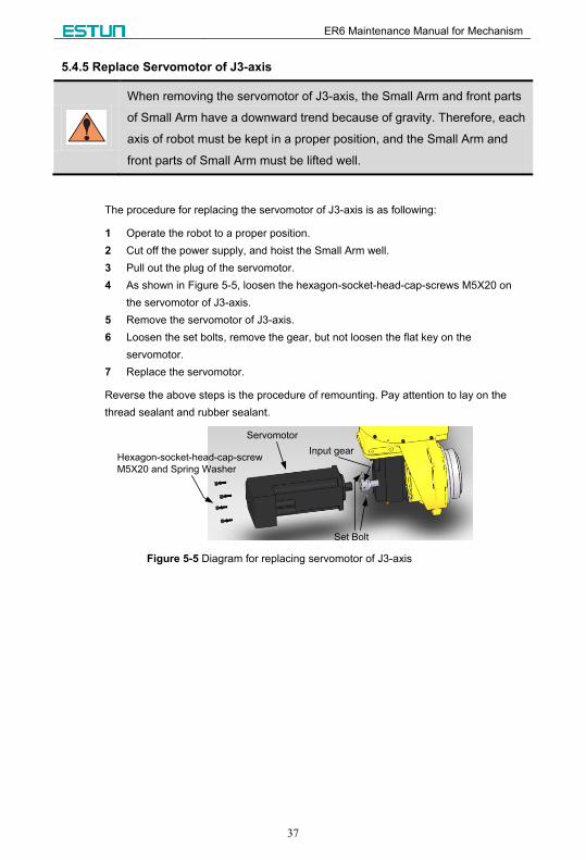
5.4.5 Replace Servomotor of J3-axis
When removing the servomotor of J3-axis, the Small Arm and front parts
of Small Arm have a downward trend because of gravity. Therefore, each
axis of robot must be kept in a proper position, and the Small Arm and
front parts of Small Arm must be lifted well.
The procedure for replacing the servomotor of J3-axis is as following:
1 Operate the robot to a proper position.
2 Cut off the power supply, and hoist the Small Arm well.
3 Pull out the plug of the servomotor.
4 As shown in Figure 5-5, loosen the hexagon-socket-head-cap-screws M5X20 on
the servomotor of J3-axis.
5 Remove the servomotor of J3-axis.
6 Loosen the set bolts, remove the gear, but not loosen the flat key on the
servomotor.
7 Replace the servomotor.
Reverse the above steps is the procedure of remounting. Pay attention to lay on the
thread sealant and rubber sealant.
Hexagon-socket-head-cap-screw
M5X20 and Spring Washer
Servomotor
Input gear
Set Bolt
Figure 5-5 Diagram for replacing servomotor of J3-axis
ER6 Maintenance Manual for Mechanism
38
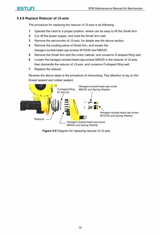
5.4.6 Replace Reducer of J3-axis
The procedure for replacing the reducer of J3-axis is as following:
1 Operate the robot to a proper position, where can be easy to lift the Small Arm.
2 Cut off the power supply, and hoist the Small Arm well.
3 Remove the servomotor of J3-axis, for details see the above section.
4 Remove the locating piece of Small Arm, and loosen the
hexagon-socket-head-cap-screws M10X30 and M6X25.
5 Remove the Small Arm and the motor cabinet, and conserve O-shaped Ring well.
6 Loosen the hexagon-socket-head-cap-screws M5X25 in the reducer of J3-axis,
then dismantle the reducer of J3-axis, and conserve O-shaped Ring well.
7 Replace the reducer.
Reverse the above steps is the procedure of remounting. Pay attention to lay on the
thread sealant and rubber sealant.
Reducer
O-shaped Ring
87.5X3.55
Hexagon-socket-head-cap-screw
M5X25 and Spring Washer
Hexagon-socket-head-cap-screw
M6X25 and Spring Washer
Hexagon-socket-head-cap-screw
M10X30 and Spring Washer
Figure 5-6 Diagram for replacing reducer of J3-axis
ER6 Maintenance Manual for Mechanism
39
Chapter 6 Scrapped Robot
Scrap part components of robot is likely to harm to the environment.
Therefore, you must obey comply with the local regulations and rule of
law.
Fasten the robot, in case CASUALTIES or other equipment damaged,
when you prepare for the scrapping, even if you just want to store
temporarily.

ER6 Maintenance Manual for Mechanism
40
Chapter 7 The Referenced Standards
This chapter is the referenced standards this manual referred.
GB 2893-2008 Safety colors
GB 2894-1996 Safety signs
GB 4053.3-1993 Safety requirements for fixed industrial protective railings
GB 5083 General rules for designing the production facilities in accordance with
safety and health requirements
GB/T 15706.1-1995 Safety of machinery--Basic concept, general principles for
design--Part 1: Basic terminology, methodology
GB/T 15706.2-1995 Safety of machinery--Basic concepts, general principles for
design--Part 2: Technical principles and specifications
GB/T 20867-2007 Industrial robot--Safety implementation specification
GB/T 11291-1997 Industrial robots-Safety specification
GB/T 5226.1-1996 Electrical equipment of industrial machines--Part 1: General
requirements
GB/T 12642-2001 Industrial robots--Performance criteria and related test
methods
GB/T 12644-2001 Industrial robots--Presentation of characteristics
GB/T 2423.1-2001 Environmental testing for electric and electronic and electronic
products--Part 2:Test methods
ER6 Maintenance Manual for Mechanism
41
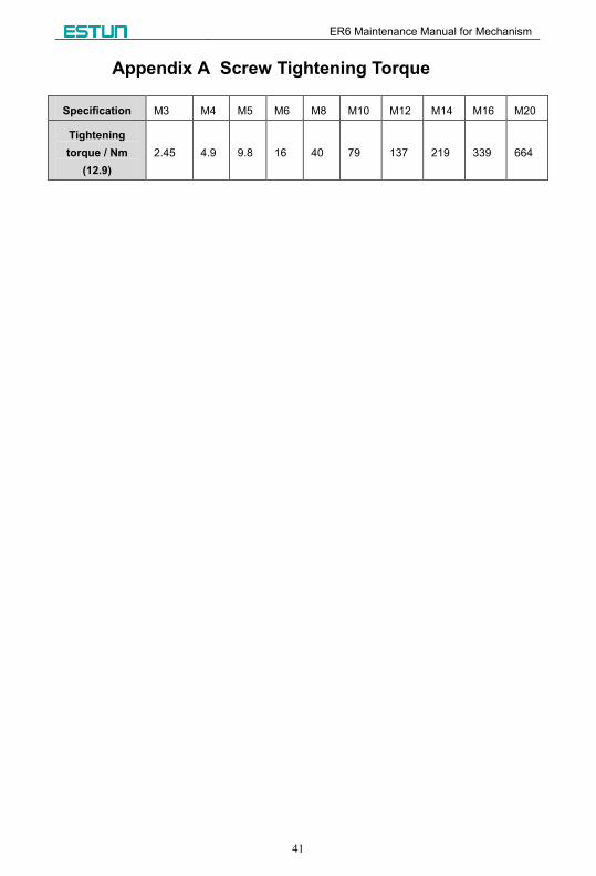
Appendix A Screw Tightening Torque
Specification M3 M4 M5 M6 M8 M10 M12 M14 M16 M20
Tightening
torque / Nm
(12.9)
2.45 4.9 9.8 16 40 79 137 219 339 664