erdc/cerl tr-10-18, development of the army facility ... · pdf filedependency index for...
TRANSCRIPT

ERD
C/CE
RL T
R-10
-18
Installation Technology Transfer Program
Development of the Army Facility Mission Dependency Index for Infrastructure Asset Management
Cons
truc
tion
Engi
neer
ing
Res
earc
h La
bora
tory
Michael N. Grussing, Steve Gunderson, Mary Canfield, Ed Falconer, Albert Antelman, and Samuel L. Hunter
September 2010
Approved for public release; distribution is unlimited.


Installation Technology Transfer Program ERDC/CERL TR-10-18 September 2010
Development of the Army Facility Mission Dependency Index for Infrastructure Asset Management
Michael N. Grussing and Samuel L. Hunter Construction Engineering Research Laboratory U.S. Army Engineer Research and Development Center 2902 Newmark Drive Champaign, IL 61822
Steve Gunderson, Mary Canfield, Ed Falconer, and Albert Antelman Naval Facilities Engineering Command Engineering Service Center 1100 23rd Street Port Hueneme, CA 93043
Final report Approved for public release; distribution is unlimited.
Prepared for U.S. Army Corps of Engineers Washington, DC 20314-1000
Under Project FY09-39, “MDI Methodology”
ERDC/CERL TR-10-18 ii
Abstract: This report describes a Mission Dependency Index (MDI) de-veloped for U.S. Army facility asset management. The MDI is an indicator of mission-related importance of Army infrastructure elements to be used for the purpose of providing more effective local prioritization of facilities for sustainment, restoration, and modernization (SRM) actions. It does this by evaluating the mission impact of interrupting a function or relocat-ing where it is provided. The index is reported on a scale of 0–100, and is analogous in that respect with existing Corps of Engineers Sustainment Management System (SMS) indices. As part of this work, an MDI metho-dology directly fit to Army-specific missions, facility resource capabilities, and organizational structure was developed. This was accomplished through a pilot implementation at White Sands Missile Range. The objec-tives of the demonstration were to identify Army-specific MDI criteria, de-velop a standardized implementation process, determine the steps for in-tegrating MDI information into garrison-level and Army-level facility management business processes, and identify considerations and re-quirements for incorporating Army MDI criteria into the BUILDER® SMS. The results of an MDI analysis, as facilitated using the implementation and integration procedures recommended here, will enable facility deci-sion makers to focus on infrastructure most critical to mission effective-ness.

ERDC/CERL TR-10-18 iii
Executive Summary
The U.S. Navy and U.S. Coast Guard codeveloped an operational risk me-tric called the Mission Dependency Index (MDI), which describes the rela-tive importance of an infrastructure asset (facility) in terms of its mission criticality. The MDI process documents and measures intradependencies within a mission and interdependencies between missions. This process was deployed across the Navy, Coast Guard, Air Force, and the National Aeronautics and Space Administration (NASA). This project evaluated the specific requirements to tailor the MDI process to U.S. Army missions, tasks, and facility/resource capabilities. It also developed guidance for ef-fectively implementing MDI for Army installations.
The information needed to calculate the MDI metric is generated from in-terviews with operations and facility decision makers. The first step in the MDI process is to succinctly categorize the list of missions performed at each installation and identify the points of contact (POC) for each mission. Intradependencies are then created by linking the specific buildings and other support structures at the installation to each mission. For each facili-ty, the interview process then determines facility interruptability, which measures how long functions supported by the facility could be stopped without adverse impact on the mission. The interview process also deter-mines relocatability, which measures whether the mission could be relo-cated to other fixed or temporary facilities. These questions have been tai-lored to reflect the way the Army uses its facilities and responds to contingencies.
After several missions have been established and facilities have been eva-luated using this process, mission interdependencies are then assessed. Interdependencies measure the indirect effect of other facilities not con-trolled by the unit. In other words, it evaluates the dependency of one mis-sion’s output on the execution of a different mission.
The result of this process is an MDI score on a scale of 0–100 that indi-cates the importance or criticality of a facility. Because the process to ob-tain this score is standardized, the result is objective, auditable, and credi-ble. It is based on direct input from the users of the facility. A facility with a high MDI score is indicative of a critical building that needs to be main-
ERDC/CERL TR-10-18 iv
tained at a high standard in order to minimize the risk of failure and con-sequent mission disruption. A low MDI score is associated with a building of negligible criticality for which the risk of failure does not directly affect mission. A low MDI score suggests potential for divesture or demolition, especially if the building is in poor condition. By linking facilities to mis-sion, MDI scores communicate a critical and previously missing detail in infrastructure-related decision-making.
This project produced three significant results. First, the general MDI process and interview questions were tailored to be Army-specific by im-plementing the MDI at a large, complex test installation (White Sands Missile Range). Also, guidance was developed to document best practices for implementing the tailored MDI process at Army installations. Finally, the relation between the MDI process and other Army facility manage-ment systems was identified in order to improve the service-wide man-agement of mission-critical facilities.
Benefits
At both the headquarters and local garrison levels, it is important to un-derstand which facilities are mission-critical, not only for current mission requirements but also for future projected core mission requirements. Al-though the Army real property database includes an element for denoting mission-critical facilities, this metric is applied subjectively and inconsis-tently. An Army-specific MDI provides an objective means of measuring the mission dependence on facility infrastructure. The MDI enables instal-lations to determine the relationship between infrastructure and mission, and it provides a credible means for prioritizing sustainment, restoration, and modernization (SRM) requirements for existing facilities and local projects. As a consequence, resource focus is applied to those facilities providing the best military value.
Because the Army has such a large portfolio of building assets, the MDI is well suited to serve as a key measure for objectively allocating limited SRM resources to where they most benefit warfighter capabilities and missions. In addition, MDI information is beneficial in cost-effectively setting the frequency and detail of facility condition assessments, space utilization as-sessments, and security assessments for the mission-critical buildings based on importance. Finally, the MDI represents a key data element that could be beneficially applied to condition-level standards definition,

ERDC/CERL TR-10-18 v
project prioritization, identification of divesture opportunities, and physi-cal security hardening.
Also, the MDI is consistent with the requirements of Executive Order 133327, Federal Real Property Asset Management, which specifically calls for “prioritizing actions to be taken to improve the operational and finan-cial management of the agency’s real property inventory.” Both the MDI assessment process and the MDI metric support system-wide mission rea-diness and help to reduce risk by allowing the installation Directorate of Public Works (DPW) and master planning office to focus more closely on the most critical infrastructure. These results ultimately promote better allocation of SRM funding for facilities.
Costs
A full MDI assessment costs an average of $1,500 per mission sub element on the installation. Typically, installations have 25 – 50 mission sub-elements. Therefore, the cost of a traditional MDI assessment is estimated at $40K – $75K per installation. This cost covers initial mission-to-infrastructure reconnaissance, data analysis, facility operator interviews, and data followup, but does not cover travel. The amount of effort required for an MDI assessment is directly related to the quality and accuracy of in-formation in the installation’s real property database.
The cost could be significantly reduced through integration of the MDI survey into the existing Installation Status Report–Infrastructure (ISR-I) facility assessment process by having each ISR-I assessor supply the in-stallation’s interruptability and relocatability ratings. Under such an ap-proach, the cost of collecting MDI information is incorporated into the ISR-I assessment. While there is some effort related to training the per-sonnel to provide the interruptability and relocatability ratings, this can be included in the ISR-I training process. That is the recommendation based on the results of this project.
Implementation and maintenance requirements
In order for the Army to collect MDI information with the least cost and least change to current processes, modifications are necessary to the Army ISR-I criteria to include interruptability and relocatability ratings for each facility. This change would allow for flexible and easy maintenance of data as mission requirements change.

ERDC/CERL TR-10-18 vi
ISR-I assessors providing the data need proper training in order to pro-duce consistent results. Personnel with extensive training in the MDI in-terview process can facilitate the initial data gathering effort to ensure the most accurate and consistent results.
MDI information can be stored in the BUILDER Sustainment Manage-ment System (SMS) program and used in facility SRM project prioritiza-tion. The MDI score, along with the component interruptability and relo-catability ratings shall be stored for each facility. The research team also recommends MDI information be added as data elements to the Army’s real property database. Because MDI is an indicator of the critical nature of the installation’s infrastructure, the information must be appropriately safeguarded and handled as For Official Use Only (FOUO) data.
Recommendations
The research team recommends that data on facility interruptability and relocatability is collected as part of an annual ISR-I process. This practice would provide the necessary flexibility to rapidly update information as missions change and would make the data collection process less burden-some.
The team also recommends that the first focus of MDI assessment be all tier 1 facilities, then all general support elements at each installation since those have the most interdependence among missions. Such facilities in-clude those supporting fire protection, water distribution, electric service, communications, transportation, DPW, and similar basic support ele-ments. Next, MDI assessment should focus on facilities supporting the di-rect mission elements for each installation. Administrative facilities, hous-ing facilities, and other general facilities should be defaulted to Army-wide MDI values as appropriate.
It also is recommended that MDI information be stored in the BUILDER SMS for use in facility SRM project prioritization. The MDI score, along with the component interruptability and relocatability ratings, should be stored for each facility. It is recommended MDI information also be added as data elements to the Army real property database.
ERDC/CERL TR-10-18 vii
Table of Contents Executive Summary ..................................................................................................................................... iii
List of Figures and Tables........................................................................................................................... ix
Preface .............................................................................................................................................................x
Unit Conversion Factors ............................................................................................................................. xi
1 Introduction ............................................................................................................................................ 1
1.1 Background .................................................................................................................... 1 1.2 Objectives ....................................................................................................................... 2 1.3 Approach ........................................................................................................................ 2 1.4 MDI terms ...................................................................................................................... 3 1.5 Mode of technology transfer ......................................................................................... 3
2 Measuring Facility Mission Dependency ......................................................................................... 5
2.1 Intradependencies and interdependencies ................................................................. 5 2.2 Calculating the MDI score ............................................................................................. 9 2.3 MDI scoring examples ................................................................................................. 10 2.4 MDI Scale ..................................................................................................................... 11
3 MDI Implementation Process ...........................................................................................................12
3.1 The seven-step process ............................................................................................... 12 3.2 Prerequisites for the MDI implementation process ................................................... 16
3.2.1 Training ...................................................................................................................... 16 3.2.2 MDI Reconnaissance ................................................................................................ 16 3.2.3 Scheduling interviews ............................................................................................... 17
4 Demonstration MDI Implementation ..............................................................................................18
5 Using MDI Information for Facility Management ......................................................................... 21
6 Army MDI Implementation Considerations ................................................................................... 23
6.1 MDI survey costs ......................................................................................................... 23 6.2 Implementation and maintenance ............................................................................. 23 6.3 Enterprise IT considerations ....................................................................................... 24 6.4 Linkage with the ISR-I .................................................................................................. 24 6.5 Linkage with Army Mapper .......................................................................................... 25
7 Summary and Recommendations ................................................................................................... 26
7.1 Summary ...................................................................................................................... 26 7.2 Recommendations ...................................................................................................... 27
References ................................................................................................................................................... 28
ERDC/CERL TR-10-18 viii
Acronyms and Abbreviations .................................................................................................................... 29
Appendix A: WSMR Functional Areas ..................................................................................................... 31
Appendix B: Unit Interview Sheet ............................................................................................................ 36
Appendix C: Intradependency Questions ............................................................................................... 37
Appendix D: Interdependency Questions ............................................................................................... 39
Report Documentation Page
ERDC/CERL TR-10-18 ix
List of Figures and Tables
Figures
Figure 1. Intradependency — mission dependency within a Functional Area, or MDw (NAVFAC ESC 2010). ...................................................................................................................................... 5
Figure 2. Interdependency — mission dependency between Functional Areas, or MDb (NAVFAC ESC 2010). ...................................................................................................................................... 7
Figure 3. MDI severity scale. ....................................................................................................................... 11
Figure 4. MDI score distribution at WSMR. .............................................................................................. 19
Tables
Table 1. Intradependency (MDw) scoring matrix. ...................................................................................... 7
Table 2. Interdependency (MDb) scoring matrix. ....................................................................................... 9
Table 3. WSMR Functional Areas. .............................................................................................................. 19
Table 4. Example facility MDI spreadsheet. .............................................................................................. 20
Table 5. MDI and CI correlation matrix. ..................................................................................................... 22
ERDC/CERL TR-10-18 x
Preface
This study was conducted for the U.S. Army Assistant Chief of Staff for In-stallation Management (ACSIM) under Installation Technology Transfer Program (ITTP) Project FY09-39, “MDI Methodology.” The technical re-viewer for ACSIM was Philip Columbus, DAIM-ODF.
The work was performed by the Engineering Processes Branch (CF-N) of the Facilities Division (CF), U.S. Army Engineer Research and Develop-ment Center – Construction Engineering Research Laboratory (ERDC-CERL). The ITTP Program Manager was Kelly M. Dilks, CEERD-CF-N. At the time of publication, Donald K. Hicks was Chief, CEERD-CF-N; L. Mi-chael Golish was Chief, CEERD-CF; and Martin J. Savoie, CEERD-CV-ZT, was the Technical Director for Installations. The Deputy Director of ERDC-CERL was Dr. Kirankumar Topudurti and the Director was Dr. Ilk-er Adiguzel.
COL Gary E. Johnston was the Commander and Executive Director of ERDC, and Dr. Jeffery P. Holland was the Director.
DISCLAIMER: The contents of this report are not to be used for advertising, publication, or promotional purposes. Citation of trade names does not constitute an official endorsement or approval of the use of such commercial products. All product names and trademarks cited are the property of their respective owners. The findings of this report are not to be construed as an official Department of the Army position unless so designated by other authorized documents. DESTROY THIS REPORT WHEN NO LONGER NEEDED. DO NOT RETURN IT TO THE ORIGINATOR.
ERDC/CERL TR-10-18 xi
Unit Conversion Factors
Multiply By To Obtain
acres 4,046.873 square meters
cubic feet 0.02831685 cubic meters
cubic inches 1.6387064 E-05 cubic meters
cubic yards 0.7645549 cubic meters
degrees (angle) 0.01745329 radians
degrees Fahrenheit (F-32)/1.8 degrees Celsius
feet 0.3048 meters
gallons (U.S. liquid) 3.785412 E-03 cubic meters
horsepower (550 foot-pounds force per second) 745.6999 watts
inches 0.0254 meters
miles (U.S. statute) 1,609.347 meters
miles per hour 0.44704 meters per second
pounds (mass) 0.45359237 kilograms
pounds (mass) per cubic inch 2.757990 E+04 kilograms per cubic meter
square feet 0.09290304 square meters
square inches 6.4516 E-04 square meters
square yards 0.8361274 square meters
tons (2,000 pounds, mass) 907.1847 kilograms
yards 0.9144 meters

ERDC/CERL TR-10-18 xii

ERDC/CERL TR-10-18 1
1 Introduction
1.1 Background
The Mission Dependency Index (MDI) is a risk-based metric to link facili-ties to specific mission elements. The MDI was developed by the Naval Fa-cilities Engineering Command Engineering Service Center (Antelman and Miller 2002) and the U.S. Coast Guard Office of Civil Engineering. It was successfully deployed at Navy, Coast Guard and National Aeronautics and Space Administration (NASA) installations. MDI scores identify the severi-ty of loss of mission-enabling facilities and infrastructure.
This index supports and is consistent with all Federal facility asset man-agement principles, and it is endorsed by the General Services Administra-tion, the National Academy of Sciences’ National Research Council, the Federal Facilities Council, the Association of Higher Education Facility Of-ficers (APPA), American Society of Civil Engineering, and the Internation-al Facilities Management Association (IFMA).
It uses operational risk management (ORM) techniques of probability and severity and applies them to facilities in terms of interruptability, reloca-tability, and replaceability. The process of determining an MDI also con-siders factors such as, environmental hazards, high cost equipment, high personnel occupancy, unique (one of a kind) facilities, emergency facili-ties, quality of life, and safety.
The MDI also takes into account mission dependencies operating within an organizational component (intradependencies) those operating be-tween or among organizational components (interdependencies). It does this through a structured interview process to capture the “experience, judgment, intuition and situational awareness of local leaders having au-thority over local operational and facility decisions” (Antelman and Miller 2002). The product of the interviews is a quantitative score normalized over a scale from zero to one hundred, with higher scores representing higher mission dependencies and mission critical facilities.
This assessment tool is powerful and easy to use. Owing to the structured interview process by which data are collected, the MDI procedure returns results that are consistent, repeatable, auditable, and less subjective than

ERDC/CERL TR-10-18 2
those produced by ad hoc evaluations. MDI scores communicate a critical and previously missing detail to support infrastructure-related decision making: it links facilities with their related mission elements.
The MDI is consistent with the requirements of Executive Order 133327, Federal Real Property Asset Management, which specifically calls for pri-oritizing actions to be taken to improve the operational and financial man-agement of the Federal government’s real property inventory. It also pro-vides a key component of the Defense Readiness Reporting System (DRRS-A) under Department of Defense Directive DoDD 7730.65.
1.2 Objectives
The objective of this project was to tailor the existing MDI process for Ar-my-specific missions, tasks, and facility/resource capabilities; and to de-veloped guidance for effectively implementing the MDI across Army in-stallations. Tasks supporting those objectives were development of (1) a plan for incorporating MDI data collection into the Army’s existing facility assessment process, (2) guidance for using MDI information to improve Army installation facility SRM prioritization and decision support, and (3) a plan to integrate the overall MDI process into the existing Army facility management systems, including those supporting real property, upward condition reporting, and work planning, and GIS.
1.3 Approach
The goal of MDI is not to eliminate risk, but to identify risk severity so the mission is accomplished with the minimum amount of loss.
MDI assessments are to be made by the leaders responsible for executing the installation’s mission. Their goal is to determine the risk severity of mission-enabling facilities and infrastructure. The assessments include input by the installation Department of Public Works (DPW), which is re-sponsible for managing, maintaining, and sustaining facilities, utilities, infrastructure, and land that directly supports Army missions. Prudence, experience, judgment, intuition and situational awareness of leaders di-rectly involved in the planning and execution of the mission are the critical elements in evaluating the risk severity of mission enabling infrastructure.

ERDC/CERL TR-10-18 3
1.4 MDI terms
The following terminology is specific to the MDI process:
• Functional Areas – organizational components typically including, but are not limited to, a brigade, battalion, company, platoon, or installa-tion tenant
• Functional Element – facilities and infrastructure occupied or used by a specific Functional Area, including buildings, structures, and utilities
• Intradependency (MDw) – metric for risk severity (in terms of inter-ruptability and relocatability) of Functional Elements or portions the-reof (floor or room) within a Functional Area’s sphere of control
• Interdependency (MDb) – metric for the degree of reliance (in terms of interruptability and replaceability) of other Functional Areas that pro-vide enabling products or services outside the sphere of their control.
• MDI score – a number ranging from 0–100, with 100 representing the highest risk severity (or impact) to mission
• Risk Severity – an assessment of the expected consequence.
1.5 Mode of technology transfer
This project incorporates technology into the BUILDER SMS for future use by Army Department of Public Works (DPW) personnel to manage the criticality of building assets and prioritization of SRM resources.
BUILDER is a fully web-based enterprise software platform which cur-rently supports SQL Server 7.0, 2000, and 2005 (including Express Edi-tion). Support for Oracle is also planned for the near future. All user inter-face elements run in web browsers using standard HTML and JavaScript. The pilot implementation of the BUILDER database is currently hosted on servers located and supported at ERDC-CERL, Champaign, IL. Wide-scale usage of BUILDER at several Army installations will be transitioned to a centralized data server/support center as appropriate. The configuration provides fast, secure multiuser access and automatic periodic backups of the Army BUILDER database. BUILDER went through the Department of Defense Information Assurance Certification and Accreditation Process (DIACAP) in June 2009, and it was granted an Authority to Operate (ATO) by the U.S. Army Information Systems Engineering Command in March 2010.

ERDC/CERL TR-10-18 4
Support to Army BUILDER users requiring access to facility functionality information is provided via email or telephone. This support may be pro-vided under the Army’s enterprise contract (CHESS) for services. Technic-al assistance addresses detailed software and how-to questions, diagnoses problems, and documents software errors or bugs to be communicated to the system developer. Periodic onsite support may be required to confi-gure server and database setup of the BUILDER SMS and coordinate IT integration with other Army facility management systems, including HQIIS, Army Mapper, ISR, and GFEBS. Annual user group meetings are planned to help identify and prioritize program enhancements and new features with the input by the user base.
ERDC/CERL TR-10-18 5
2 Measuring Facility Mission Dependency
2.1 Intradependencies and interdependencies
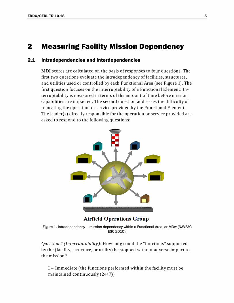
MDI scores are calculated on the basis of responses to four questions. The first two questions evaluate the intradependency of facilities, structures, and utilities used or controlled by each Functional Area (see Figure 1). The first question focuses on the interruptability of a Functional Element. In-terruptability is measured in terms of the amount of time before mission capabilities are impacted. The second question addresses the difficulty of relocating the operation or service provided by the Functional Element. The leader(s) directly responsible for the operation or service provided are asked to respond to the following questions:
Figure 1. Intradependency — mission dependency within a Functional Area, or MDw (NAVFAC
ESC 2010).
Question 1 (Interruptability): How long could the “functions” supported by the (facility, structure, or utility) be stopped without adverse impact to the mission?
I – Immediate (the functions performed within the facility must be maintained continuously (24/7))

ERDC/CERL TR-10-18 6
U – Urgent (minutes, not to exceed 1 hour)
B – Brief (hours, not to exceed 24 hours)
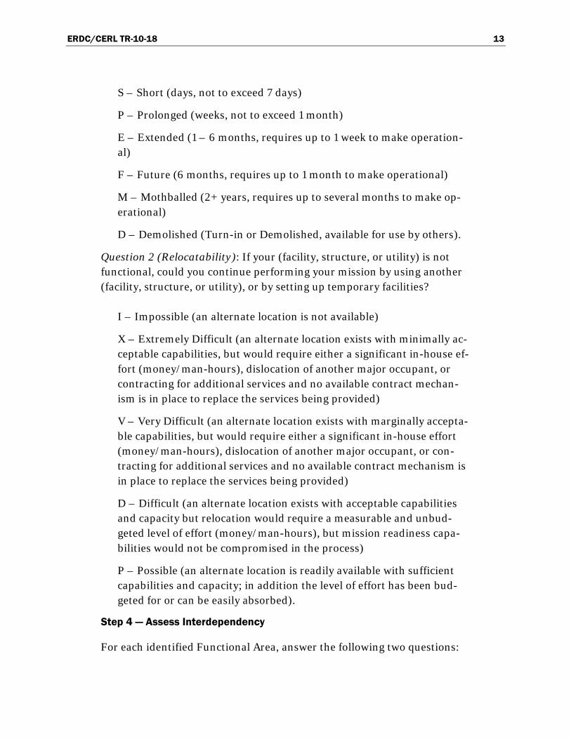
S – Short (days, not to exceed 7 days)
P – Prolonged (weeks, not to exceed 1 month)
E – Extended (1 – 6 months, requires up to 1 week to make operation-al)
F – Future (6 months, requires up to 1 month to make operational)
M – Mothballed (2+ years, requires up to several months to make op-erational)
D – Demolished (turn-in or demolished, available for use by others).
Question 2 (Relocatability): If your (facility, structure, or utility) is not functional, could you continue performing your mission by using another (facility, structure, or utility), or by setting up temporary facilities?
I – Impossible (an alternate location is not available)
X – Extremely Difficult (an alternate location exists with minimally ac-ceptable capabilities, but would require either a significant in-house ef-fort (money/man-hours), dislocation of another major occupant, or contracting for additional services and no available contract mechan-ism is in place to replace the services being provided)
V – Very Difficult (an alternate location exists with marginally accepta-ble capabilities, but would require either a significant in-house effort (money/man-hours), dislocation of another major occupant, or con-tracting for additional services and no available contract mechanism is in place to replace the services being provided)
D – Difficult (an alternate location exists with acceptable capabilities and capacity but relocation would require a measurable and unbud-geted level of effort (money/man-hours), but mission readiness capa-bilities would not be compromised in the process)
P – Possible (an alternate location is readily available with sufficient capabilities and capacity; in addition the level of effort has been bud-geted for or can be easily absorbed).
ERDC/CERL TR-10-18 7
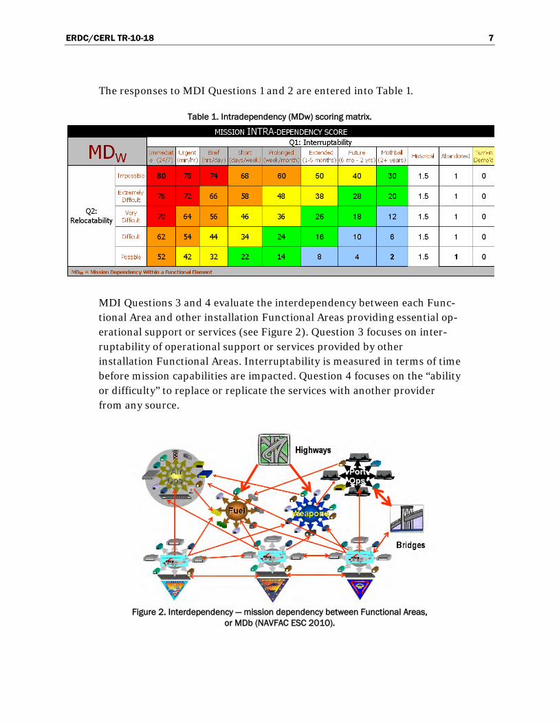
The responses to MDI Questions 1 and 2 are entered into Table 1.
Table 1. Intradependency (MDw) scoring matrix.
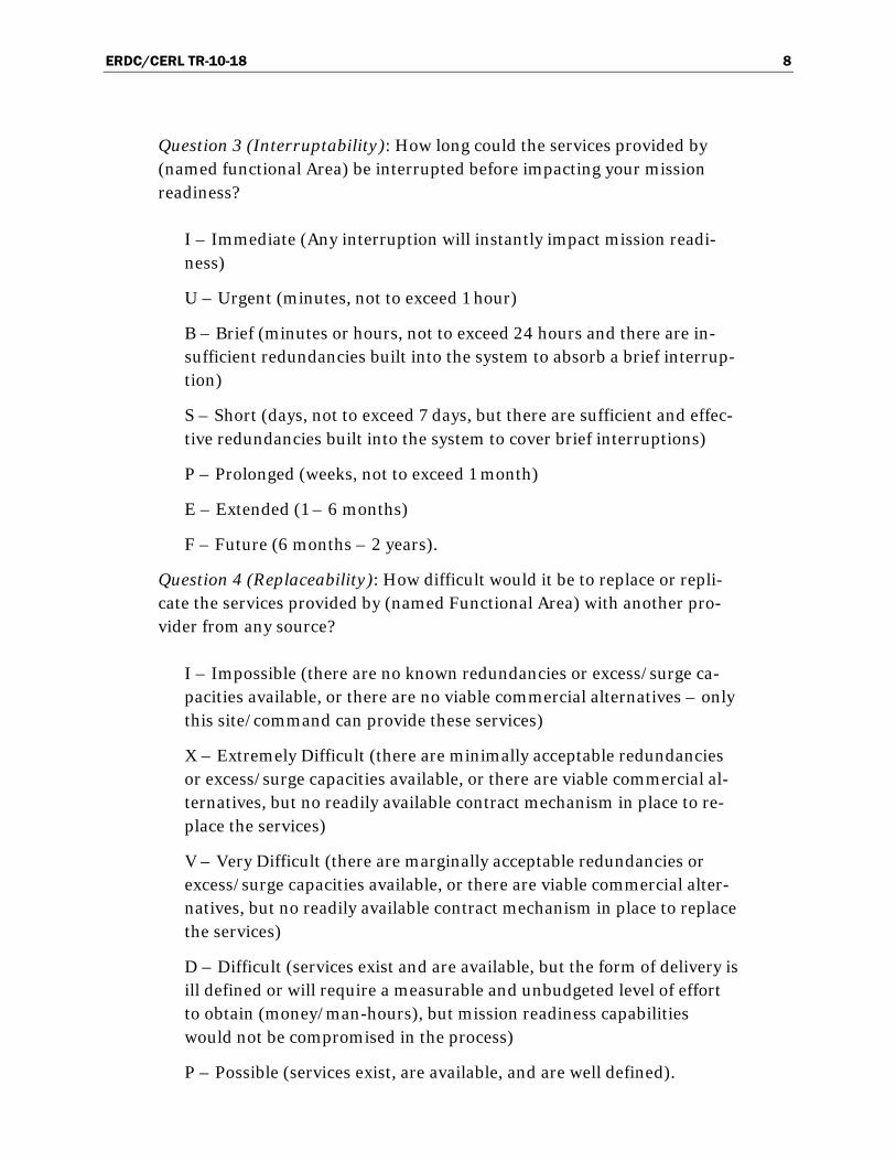
MDI Questions 3 and 4 evaluate the interdependency between each Func-tional Area and other installation Functional Areas providing essential op-erational support or services (see Figure 2). Question 3 focuses on inter-ruptability of operational support or services provided by other installation Functional Areas. Interruptability is measured in terms of time before mission capabilities are impacted. Question 4 focuses on the “ability or difficulty” to replace or replicate the services with another provider from any source.
Figure 2. Interdependency — mission dependency between Functional Areas,
or MDb (NAVFAC ESC 2010).
ERDC/CERL TR-10-18 8
Question 3 (Interruptability): How long could the services provided by (named functional Area) be interrupted before impacting your mission readiness?
I – Immediate (Any interruption will instantly impact mission readi-ness)
U – Urgent (minutes, not to exceed 1 hour)
B – Brief (minutes or hours, not to exceed 24 hours and there are in-sufficient redundancies built into the system to absorb a brief interrup-tion)
S – Short (days, not to exceed 7 days, but there are sufficient and effec-tive redundancies built into the system to cover brief interruptions)
P – Prolonged (weeks, not to exceed 1 month)
E – Extended (1 – 6 months)
F – Future (6 months – 2 years).
Question 4 (Replaceability): How difficult would it be to replace or repli-cate the services provided by (named Functional Area) with another pro-vider from any source?
I – Impossible (there are no known redundancies or excess/surge ca-pacities available, or there are no viable commercial alternatives – only this site/command can provide these services)
X – Extremely Difficult (there are minimally acceptable redundancies or excess/surge capacities available, or there are viable commercial al-ternatives, but no readily available contract mechanism in place to re-place the services)
V – Very Difficult (there are marginally acceptable redundancies or excess/surge capacities available, or there are viable commercial alter-natives, but no readily available contract mechanism in place to replace the services)
D – Difficult (services exist and are available, but the form of delivery is ill defined or will require a measurable and unbudgeted level of effort to obtain (money/man-hours), but mission readiness capabilities would not be compromised in the process)
P – Possible (services exist, are available, and are well defined).
ERDC/CERL TR-10-18 9
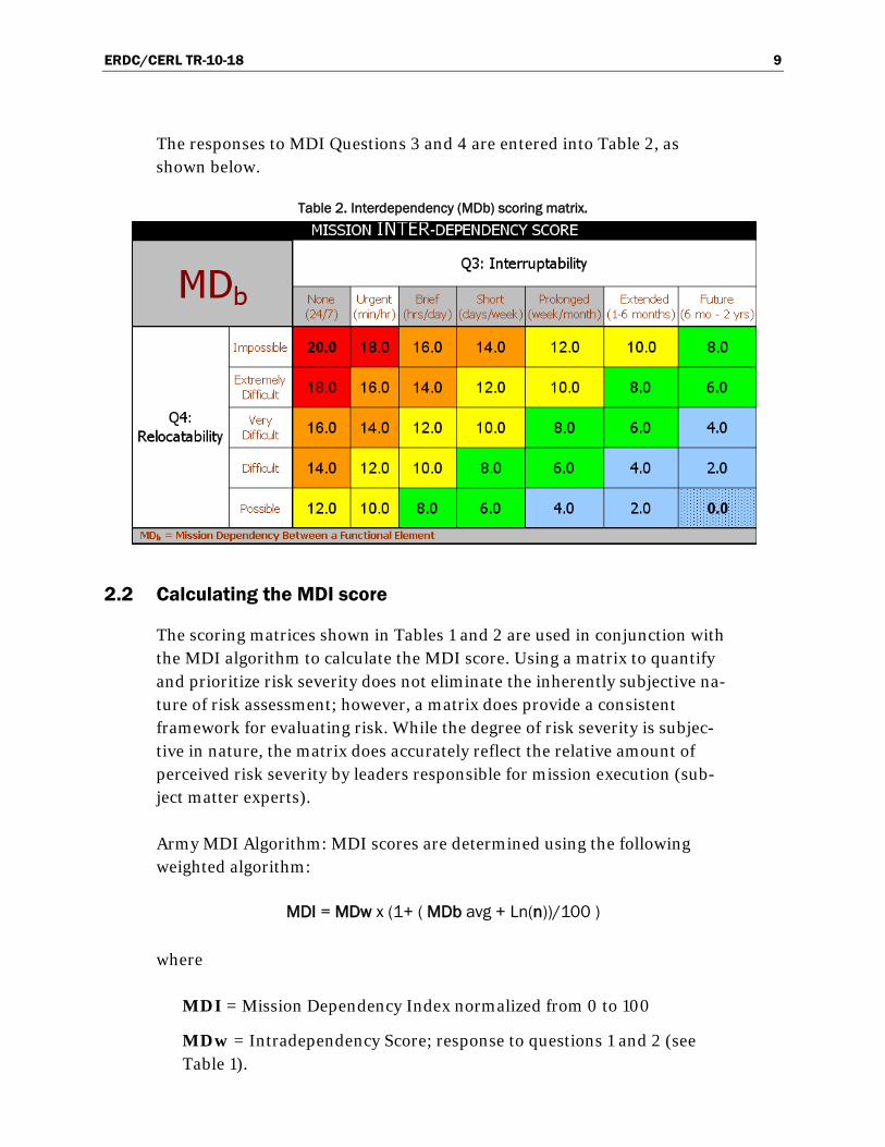
The responses to MDI Questions 3 and 4 are entered into Table 2, as shown below.
Table 2. Interdependency (MDb) scoring matrix.
2.2 Calculating the MDI score
The scoring matrices shown in Tables 1 and 2 are used in conjunction with the MDI algorithm to calculate the MDI score. Using a matrix to quantify and prioritize risk severity does not eliminate the inherently subjective na-ture of risk assessment; however, a matrix does provide a consistent framework for evaluating risk. While the degree of risk severity is subjec-tive in nature, the matrix does accurately reflect the relative amount of perceived risk severity by leaders responsible for mission execution (sub-ject matter experts).
Army MDI Algorithm: MDI scores are determined using the following weighted algorithm:
MDI = MDw x (1+ ( MDb avg + Ln(n))/100 )
where
MDI = Mission Dependency Index normalized from 0 to 100
MDw = Intradependency Score; response to questions 1 and 2 (see Table 1).
ERDC/CERL TR-10-18 10
MDb ave = (Interdependency Score): The average response to ques-tions 3 and 4, see Table 2, from other Functional Areas, in regards to the Functional Area whose MDI is being calculated.
Ln( ) = natural log function of n
n = number of Interdependencies with other Functional Areas
The fourth scoring component of MDI is the value “n” which is the number of Functional Areas identifying interdependency. The number of Func-tional Areas varies substantially from small to large installations.
The natural log function is used because the value of “n” is constrained, and diminishes as “n” increases (Air Force Instruction 90-901, 1 April 2000). The intradependency and interdependency components of the overall MDI score are weighed as follows: MDw = 80 %, MDb Average = 20 %. This is done by the interdependency amplification factor (1+(MDb Average + Ln(n))/100), which can increase the final MDI value over the MDw value by a factor of 1.00 – 1.25. This means MDI scores are mostly dependent on the subcomponent’s knowledge of its facilities (intradepen-dency). Additionally, MDw and MDb have been weighted toward interrup-tability questions 1 and 3 by a factor of 60/40. This is done because ques-tions related to interruptability are believed to be more objective than questions related to relocatability and replaceability.
2.3 MDI scoring examples
MDI limits operators to 80 points out of 100 when scoring the impact of infrastructure controlled or used by their Functional Area (MDw, intra-dependence). This limit assumes that no operator’s Functional Area is crit-ical unless other operators are dependent on the operations or services (mission enabling) they provide (MDb, interdependence).
Totally independent Functional Areas providing no support to other in-stallation Functional Areas are limited to a maximum interdependency (MDw) score of 80 (exactly at critical breakpoint, as seen in Figure 3). Therefore, only a 24/7 operating facility that is impossible to relocate is critical unless the facility were to receive high interdependency scores from other Functional Areas.
ERDC/CERL TR-10-18 11
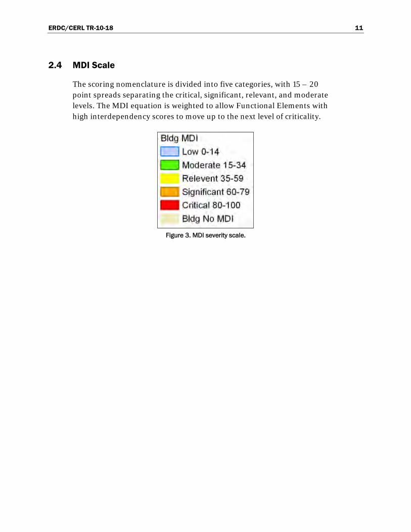
2.4 MDI Scale
The scoring nomenclature is divided into five categories, with 15 – 20 point spreads separating the critical, significant, relevant, and moderate levels. The MDI equation is weighted to allow Functional Elements with high interdependency scores to move up to the next level of criticality.
Figure 3. MDI severity scale.

ERDC/CERL TR-10-18 12
3 MDI Implementation Process
3.1 The seven-step process
The MDI is implemented using a seven-step process. MDI assessments are to be made by the leader or leaders responsible for executing the mission. He or she is responsible for determining the risk severity of mission-enabling facilities and infrastructure. Prudence, experience, judgment, in-tuition, and situational awareness of leaders directly involved in the plan-ning and execution of the mission are the critical elements in evaluating the risk severity of mission enabling infrastructure. A description of the seven-step process follows.
Step 1 — Identify Functional Areas
Functional areas are composed of two major groupings:
• Host Functional Areas, typically including Operating Forces Support, Community Support, and Base Support
• Tenants.
Step 2 — Identify Functional Elements
Functional Elements are Facilities and Infrastructure occupied or used by a Functional Area.
Step 3 — Assess Intradependency
For each Functional Element (facility or infrastructure) within a Function-al Area, answer the following two questions:
Question 1 (Interruptability): How long could the "functions" supported by the (facility, structure, or utility) be stopped without adverse impact to the mission?
I – Immediate (the functions performed within the facility must be maintained continuously (24/7))
U – Urgent (minutes, not to exceed 1 hour)
B – Brief (hours, not to exceed 24 hours)
ERDC/CERL TR-10-18 13
S – Short (days, not to exceed 7 days)
P – Prolonged (weeks, not to exceed 1 month)
E – Extended (1 – 6 months, requires up to 1 week to make operation-al)
F – Future (6 months, requires up to 1 month to make operational)
M – Mothballed (2+ years, requires up to several months to make op-erational)
D – Demolished (Turn-in or Demolished, available for use by others).
Question 2 (Relocatability): If your (facility, structure, or utility) is not functional, could you continue performing your mission by using another (facility, structure, or utility), or by setting up temporary facilities?
I – Impossible (an alternate location is not available)
X – Extremely Difficult (an alternate location exists with minimally ac-ceptable capabilities, but would require either a significant in-house ef-fort (money/man-hours), dislocation of another major occupant, or contracting for additional services and no available contract mechan-ism is in place to replace the services being provided)
V – Very Difficult (an alternate location exists with marginally accepta-ble capabilities, but would require either a significant in-house effort (money/man-hours), dislocation of another major occupant, or con-tracting for additional services and no available contract mechanism is in place to replace the services being provided)
D – Difficult (an alternate location exists with acceptable capabilities and capacity but relocation would require a measurable and unbud-geted level of effort (money/man-hours), but mission readiness capa-bilities would not be compromised in the process)
P – Possible (an alternate location is readily available with sufficient capabilities and capacity; in addition the level of effort has been bud-geted for or can be easily absorbed).
Step 4 — Assess Interdependency
For each identified Functional Area, answer the following two questions:

ERDC/CERL TR-10-18 14
Question 3 (Interruptability): How long could the services provided by (named functional Area) be interrupted before impacting your mission readiness?
I – Immediate (any interruption will instantly impact mission readi-ness)
U – Urgent (minutes, not to exceed 1 hour)
B – Brief (minutes or hours, not to exceed 24 hours and there are in-sufficient redundancies built into the system to absorb a brief interrup-tion)
S – Short (days, not to exceed 7 days, but there are sufficient and effec-tive redundancies built into the system to cover brief interruptions)
P – Prolonged (weeks, not to exceed 1 month)
E – Extended (1 – 6 months)
F – Future (6 months – 2 years).
Question 4 (Replaceability): How difficult would it be to replace or repli-cate the services provided by (named functional Area) with another pro-vider from any source?
I – Impossible (there are no known redundancies or excess/surge ca-pacities available, or there are no viable commercial alternatives – only this site/command can provide these services)
X – Extremely Difficult (there are minimally acceptable redundancies or excess/surge capacities available, or there are viable commercial al-ternatives, but no readily available contract mechanism in place to re-place the services)
V – Very Difficult (there are marginally acceptable redundancies or excess/surge capacities available, or there are viable commercial alter-natives, but no readily available contract mechanism in place to replace the services)
D – Difficult (services exist and are available, but the form of delivery is ill defined or will require a measurable and unbudgeted level of effort to obtain (money/man-hours), but mission readiness capabilities would not be compromised in the process)
P – Possible (services exist, are available, and are well defined).

ERDC/CERL TR-10-18 15
Step 5 — Calculate preliminary MDI scores
A scoring matrix is used to accomplish the fifth step of the MDI process. Using a matrix to quantify and prioritize risk severity does not reduce the inherently subjective nature of risk assessment, but it does provide a con-sistent framework for evaluating risk. While the degree of risk severity is subjective in nature, the matrix does accurately reflect the relative amount of perceived risk severity by leaders responsible for mission execution (who are subject matter experts). Using the matrix below, Intradependen-cy (MDw) and Interdependency (MDb) scores are expressed as a number.
MDI scores are determined using the following weighted algorithm:
MDI = MDw + (1+ ( MDb avg + Ln(n))/100 )
where
MDI = Mission Dependency Index normalized from 100–0 MDw = (Intradependency Score): Response to questions 1 and 2, see
Table 1. MDb ave = (Interdependency Score): The average response to questions 3
and 4 from other Functional Areas, in regards to the Functional Area of the facility whose MDI is being calculated.
Ln( ) = natural log function of n n = number of Interdependencies with other Functional Areas
Facilities or infrastructure (Functional Elements) classified as vacant or abandoned are assigned an MDI score of 1.
Facilities or infrastructure unclaimed (i.e., orphan facility) by an installa-tion Functional Area or scheduled for demolition are assigned an MDI score of 0.
Step 6 — Review MDI score accuracy
MDI scores are reviewed by each Functional Area mission commander and the installation commander for accuracy and completeness.

ERDC/CERL TR-10-18 16
Step 7 — Save data to facility real property database
The MDI score and date of survey are entered into BUILDER Sustainment Management System to be associated with facility real property file.
3.2 Prerequisites for the MDI implementation process
3.2.1 Training
Training requirements for MDI interview personnel are recommended as follows:
• one day for a training workshop • a half-day to observe the interview process. • a half-day of conducting an interview under the supervision of a skilled
interviewer.
3.2.2 MDI Reconnaissance
This prerequisite involves a visit to the installation to brief the DPW and garrison commander. In order to collect the information needed for MDI implementation, the following tasks are accomplished:
• Identify all relevant host installation Functional Areas using a standar-dized list.
• Identify all tenant Commands. • Establish a survey date. • Request that the garrison command contact all host Functional Areas
and tenants and schedule interview appointments (a 20- to 40-hour ef-fort depending on the size of the installation).
• Request that the installation senior commander send out an e-mail asking for cooperation and assistance in completing the MDI survey.
• Acquire installation maps and telephone directory. • Identify a Public Works point of contact to provide assistance during
the survey. • Request a survey team space with a telephone and computer. • Prepare MDI survey forms by downloading facilities data from the Ar-
my Real Property Inventory to the forms (a 5 – 8 day effort depending on the size of the installation and number of Functional Areas).
ERDC/CERL TR-10-18 17
3.2.3 Scheduling interviews
MDI interviews require the assistance of one person to schedule appoint-ments and act as a point of contact during the survey. Each Functional Area interviewed must provide one or more leaders (Commanding Officer, Executive Officer, senior enlisted noncommissioned officer, or senior civi-lian to speak knowledgeably about the mission, mission-enabling infra-structure, and interdependencies with other missions on and off the instal-lation) for each Functional Area interview. Interviews typically take approximately 45 minutes to complete, depending on the number of assets associated with each Functional Element.

ERDC/CERL TR-10-18 18
4 Demonstration MDI Implementation
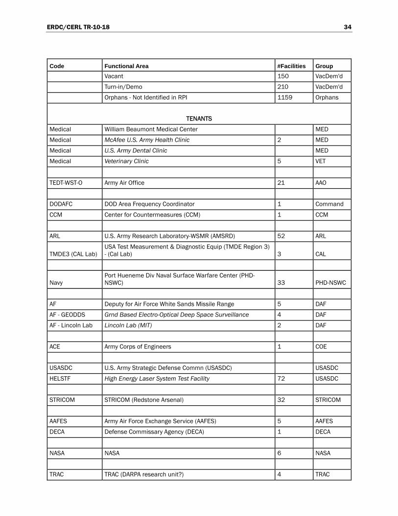
White Sands Missile Range (WSMR), NM, was selected as a demonstra-tion installation for MDI to show that the MDI can effectively be used to document mission dependencies for highly complex operations. WSMR hosts a number of testing operations for different DoD components, and as such it has a large number of Functional Areas and tenants. DPW per-sonnel at the installation assisted in the MDI process to identify all Func-tional Areas at the installation. The following information was used to identify Functional Elements controlled or used by each Functional Area:
• White Sands real property information • installation telephone directory • the Installation Geospatial Information and Services (IGI&S) database.
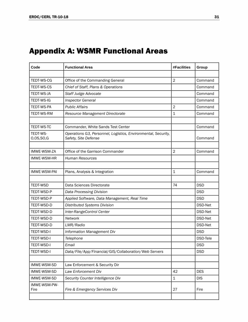
A total of 38 Functional Areas, 19 hosts, and 19 tenants were identified for survey (see Appendix A). Table 3 shows an example breakdown of the Functional Areas (missions) at WSMR.
Figure 4 shows the distribution of MDI scores at WSMR. A total of 855 Functional Elements (facilities were rated). The MDI survey was con-ducted by a survey team consisting of three experienced Navy MDI sur-veyors. Surveyors were also observed and assisted by ERDC-CERL and WSMR personnel.

ERDC/CERL TR-10-18 19
Table 3. WSMR Functional Areas.
Figure 4. MDI score distribution at WSMR.
l\IDI WSl\IR FUNCTIONAL AREAS
Code Functional Area IF acilities Group
iTEDT-WS-CG Office of the Commandinq General 2 Command ifEDT-WS-CS Chief of Staff, Plans & Operations Command ifEDT-WS-JA Staff Judae Advocate Command ifEDT-WS-IG Inspector General Command ifEDT-WS-PA Public Affairs 2 Command ifEDT-WS-RM Resource Management Directorate 1 Command iTEDT-WS-TC Commander, White Sands Test Center Command ifEDT-WS-O,OS,SO,G Operations G3, Personnel, Logistics, Environmental, Security, Safety, Site De Command IMWE-WSM-ZA Office of the Garrison Commander 2 Command
IMWE-WSM-HR Human Resources IMWE-WSM-PAI Plans, Analvsis & lnteqration 1 Command ifEDT-WSD Data Sciences Directorate 74 DSD ifEDT-WSD-P Data Processina Division DSD ifEDT-WSD-P Applied Software, Data Management, Real Time DSD ifEDT-WSD-D Distributed Systems Division DSD-Net ifEDT-WSD-D lnter-RanaeControl Center DSD-Net ifEDT-WSD-D Network DSD-Net ifEDT-WSD-D LMR/Radio DSD-Net ifEDT-WSD-1 Information Management Div DSD ifEDT-WSD-1 Telephone DSD-Tele ifEDT-WSD-1 Email DSD ifEDT-WSD-1 Dat&'Filel APJ:IFinanciaVGIS/Collaboratior>'Web Servers DSD IMWE-WSM-SD Law Enforcement & Security Dir IMWE-WSM-SD Law Enforcement Div 42 DES IMWE-WSM-SD Security Counter Intelligence Div 1 DIS IMWE-WSM-PW-Fire Fire & Emeraencv Services Div 27 Fire IMWE-WSM-MW Dir. Community Activities & Housing 63 MWR IMWE-WSM-CH Staff Chaplain 3 Chaplain
TEDT-WSM Materiel Test Directorate 494 MTD ifEDT-WSM-T Missiles & Space Div MTD ifEDT-WSM-F Future Force Div MTD ifEDT-WSM-0 Systems Petformance & Assessment Div MTD
WSMR Histogram of MDI scores Low0-14, Moderate 15-34, Relevant 35-M, Slgntncant 56-79, CrltlealaJ-100
•1(1(1
90
;)I)
7(1
(;' c
1$1)
; :::11)
" f "- 40
:-'.1)
)I)
·o
I l. J.l1. ,~II I. .J .. u.l. ,J.l ,,.~tl.ll , .. ... 11.. L .. k ,.J 1./,,o o) 1.,,,,,1.1 ,.,.,~ c,.,., 0) ',,. u " ~ " l<l ~; '" ~ • ~ J! ~ ->! ~ t-i .. ·- 1.! H ~ ~ t:
MDI Score

ERDC/CERL TR-10-18 20
Example results by facility are provided in Table 4.
Table 4. Example facility MDI spreadsheet.
Each data element (represented in the column headings) is defined below:
• Interview – the Functional Area Interview associated with each facility • Site – the physical location of the facility on base • Fac No – The Facility Number from Real Property Inventory • Facility Name – The Facility Name Descriptor • Comments – Comments appended during interview to better describe
facility (helps improve quality of real property information) • Q1 – Answer to Question 1 (Intradependency/Interruptability) • Q2 - Answer to Question 2 (Intradependency/Relocatability) • MDw – Interdependency Score • Group – Service Group for Interdependency • MDb avg – Additional score for interdependency • n – number of dependent missions • MDI – overall facility Mission Dependency Index (MDI) score.
ERDC/CERL TR-10-18 21
5 Using MDI Information for Facility Management
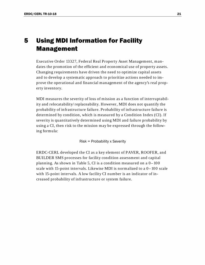
Executive Order 13327, Federal Real Property Asset Management, man-dates the promotion of the efficient and economical use of property assets. Changing requirements have driven the need to optimize capital assets and to develop a systematic approach to prioritize actions needed to im-prove the operational and financial management of the agency’s real prop-erty inventory.
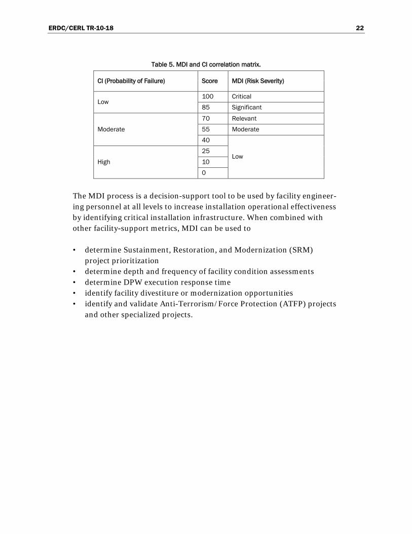
MDI measures the severity of loss of mission as a function of interruptabil-ity and relocatability/replaceability. However, MDI does not quantify the probability of infrastructure failure. Probability of infrastructure failure is determined by condition, which is measured by a Condition Index (CI). If severity is quantitatively determined using MDI and failure probability by using a CI, then risk to the mission may be expressed through the follow-ing formula:
Risk = Probability x Severity
ERDC-CERL developed the CI as a key element of PAVER, ROOFER, and BUILDER SMS processes for facility condition assessment and capital planning. As shown in Table 5, CI is a condition measured on a 0–100 scale with 15-point intervals. Likewise MDI is normalized to a 0–100 scale with 15-point intervals. A low facility CI number is an indicator of in-creased probability of infrastructure or system failure.
ERDC/CERL TR-10-18 22
Table 5. MDI and CI correlation matrix.
CI (Probability of Failure) Score MDI (Risk Severity)
Low 100 Critical
85 Significant
Moderate
70 Relevant
55 Moderate
40
Low High
25
10
0
The MDI process is a decision-support tool to be used by facility engineer-ing personnel at all levels to increase installation operational effectiveness by identifying critical installation infrastructure. When combined with other facility-support metrics, MDI can be used to
• determine Sustainment, Restoration, and Modernization (SRM) project prioritization
• determine depth and frequency of facility condition assessments • determine DPW execution response time • identify facility divestiture or modernization opportunities • identify and validate Anti-Terrorism/Force Protection (ATFP) projects
and other specialized projects.

ERDC/CERL TR-10-18 23
6 Army MDI Implementation Considerations
This chapter covers issues to be considered for effective implementation of the MDI throughout the Army. It includes discussion of changes that would need to be made in order to promote a cost-effective, well integrated process.
6.1 MDI survey costs
The cost for a full MDI assessment at an installation averages approx-imately $1,500 per mission sub-element hosted. An installation typically has 25 – 50 mission sub-elements, so a standard MDI assessment is esti-mated at $40,000 – $60,000 per installation. This includes initial mis-sion-to-infrastructure reconnaissance, data analysis, facility operator in-terviews, and data follow-up, but does not include travel. The effort involved in an MDI assessment is directly related to the quality and accu-racy of information in the installation’s real property database.
One option to considerably reduce cost would be to integrate the MDI as-sessment into the existing Installation Status Report–Infrastructure (ISR-I) facility assessment process by having each ISR-I assessor supply the in-stallation’s interruptability and relocatability ratings. Under such an ap-proach, the cost of collecting MDI information is incorporated into the ISR-I assessment. While there is some effort related to training the per-sonnel to provide the interruptability and relocatability ratings, that can be included in the ISR-I training process.
6.2 Implementation and maintenance
In order for the Army to accomplish the collection of MDI information most cost effectively and with the least change to existing Army processes, ISR-I criteria would need to be modified to include the interruptability and relocatability ratings for each facility. This modification would pro-mote flexible and easy maintenance of data as mission requirements change.
The ISR-I assessors providing the data require proper training to achieve consistent results. Personnel previously trained extensively in the MDI in-
ERDC/CERL TR-10-18 24
terview process should facilitate the initial data gathering effort to assure the most accurate and consistent results.
MDI information should be stored in the BUILDER SMS program for use in facility SRM project prioritization. The MDI score, along with the com-ponent interruptability and relocatability ratings, should be stored for each facility. It is recommended that MDI information also be added as data elements to the Army’s real property database. Because MDI is an in-dicator of the critical nature of an installation’s infrastructure, the infor-mation must be appropriately safeguarded and stamped For Official Use Only (FOUO).
6.3 Enterprise IT considerations
The details of the MDI surveys should be stored in the BUILDER SMS for analysis of facility metrics to be used in SRM planning. BUILDER uses an open data architecture that enables free communication with other elec-tronic Army management systems and data repositories. These communi-cation links are created using web services and XML exchange features. To effectively improve integration with other Army systems that manage and report facility information, this information exchange needs to be robust and seamless.
BUILDER is able to provide the following capacities for MDI manage-ment:
• Calculate default MDI scores based on catcode. • Provide a repository for MDI survey information. • House a list of typical installation Functional Areas • Provide a procedure for changing an existing MDI score for a facility
through the ISR-I assessment process.
It should be noted that MDI scores are time dependent, and they may be impacted by a change in mission, increased mission tempo, infrastructure availability, capacity, condition, and functionality. BUILDER provides a process to accommodate these time-dependent changes.
6.4 Linkage with the ISR-I
Army installations report the condition and readiness of their facilities us-ing the Installation Status Report–Infrastructure (ISR-I). Building tenants

ERDC/CERL TR-10-18 25
are primarily responsible for providing a condition/readiness rating based on standardized guidelines that consider several different aspects of the facility. While the ISR-I assessment process attempts to identify facility requirements affecting readiness and mission, there is not a formalized process to incorporate mission interruptability and relocatability into the rating. By linking those mission metrics to the ISR-I, Army installations will be able to collect data and evaluate priorities for their existing build-ings based on mission criticality. With ISR-I information feeding into BUILDER, information updates to the real property database will be readi-ly available for planning purposes.
6.5 Linkage with Army Mapper
Army Mapper provides enterprise-wide GIS support. It is a geographic da-ta repository for all base-related infrastructures to be used for master planning purposes. The open architecture of BUILDER allows for linkage and integration of Army Mapper data tables with BUILDER. Such integra-tion would allow for building information, displayed from building foot-print shapefiles, to be overlaid with other infrastructure domains such as pavements, railroads, airfield, and other utilities, to provide a comprehen-sive view of the installation in native GIS data architecture.
ERDC/CERL TR-10-18 26
7 Summary and Recommendations
7.1 Summary
The Mission Dependency Index (MDI) was developed to provide a key measure for the objective allocation of SRM resources to infrastructure as-sets in order to provide maximum benefit to the warfighting mission. MDI data also are well suited for cost-effectively setting the frequency and de-tail of facility condition assessments, space utilization assessments, and security assessments for mission-critical buildings based on rating. Final-ly, the MDI represents a key data element that could be beneficially ap-plied to condition-level standards definition, project prioritization, identi-fication of divesture opportunities, and physical security hardening. Both the MDI assessment process and MDI metric support system-wide mis-sion readiness. They help to reduce risk by allowing the installation to fo-cus more directly on the most critical infrastructure. These benefits ulti-mately promote better allocation of SRM funding for facilities.
The information needed to calculate the MDI metric is generated through interviews with operations and facility decision makers who are the most authoritative subject-matter experts on their installation’s infrastructure. These interviews are the basis for identifying infrastructure-dependent missions and each facility’s interruptability and relocatability with re-spect to their missions. Interruptability indicates how long facility opera-tions could be interrupted without adverse mission impact, and relocata-bility indicates how readily operations could be relocated to avoid adverse impact. After missions have been identified and facilities have been eva-luated for interruptability and relocatability, the MDI process assesses mission interdependencies. An interdependency is a measure of one mis-sion’s output on the execution of a different mission.
An MDI score, using a rating scale of 0–100 that is analogous to indices created by Sustainment Management Systems (SMSs) such as BUILDER, indicates a facility’s mission criticality. Like other SMS indices, the MDI score is assigned using standardized procedures that produce objective, auditable, and credible ratings. A high MDI score indicates a mission-critical building that needs to be maintained at a high standard of functio-nality. A low MDI score indicates of negligible mission-criticality, and may suggest the potential for divesture or demolition. By linking each facility to
ERDC/CERL TR-10-18 27
the installation’s mission, MDI scores communicate a critical detail not previously available to infrastructure decision makers.
This project produced three significant results. First, the general MDI process and interview questions were tailored to Army requirements by implementing the MDI at a large, complex test installation (White Sands Missile Range). Second, best practices for implementing the tailored MDI process at Army installations were documented for prospective use in fu-ture formal guidance. Third, the relation between the MDI process and other Army facility management systems was identified in order to facili-tate the service-wide management of mission-critical facilities.
7.2 Recommendations
The authors recommend that data on facility interruptability and relocata-bility be collected as part of an annual ISR-I process. This approach would provide flexibility to provide up-to-date information as missions change, while making the data collection process less burdensome. In order to achieve consistent results, the ISR-I assessors providing the data must be properly trained. As implementation of this data collection begins, per-sonnel with previous extensive training in the MDI interview process should facilitate the initial data gathering effort in order to assure the most accurate and consistent results.
It is also recommended that MDI assessments focus first on all Tier 1 mis-sion elements, then all general support elements at each installation, since these two categories involve the highest degree of interdependence among missions. These include facilities supporting fire, water, electric, commu-nications, transportation, DPW, and other basic support elements. Next, efforts should focus on facilities supporting the direct mission elements for each installation. Administrative facilities, housing facilities, and other general facilities should be defaulted to Army-wide MDI values as appro-priate.
Finally, it is recommended that MDI information be stored in the BUILDER SMS to facilitate infrastructure SRM project prioritization. The MDI score, along with the component interruptability and relocatability ratings, should be stored for each facility. It is recommended MDI infor-mation also be added as data elements to the Army’s real property data-base.

ERDC/CERL TR-10-18 28
References Air Force Instruction 90-901, 1 April 2000, Operational Risk Management. http://www.e-
publishing.af.mil/shared/media/epubs/AFI90-901.pdf
Amekudzi, A., and S. McNeil. 2008. Infrastructure Reporting and Asset Management, Pages 141-146, Best Practices and Opportunities. Reston, VA: American Society of Civil Engineering.
Antelman, A., and C. Miller. 2002. Mission Dependency Index Validation Report. Special Publication SP-2113-SHR. Port Hueneme, CA: Naval Facilities Engineering Command, Naval Facilities Engineering Service Center.
http://www.fmlink.com/ProfResources/BestPractices/
http://www7.nationalacademies.org/FFC/Albert_Antelman_USNavy_Facility_Management_Triage_Oct_06_WP.pdf
http://www.appa.org/files/pressreleases/070906_execsummary_buildingsais.pdf
http://www.ifma.org/learning/events/fm3d08/files/best%20practices/3.1%20FM%20Triage%20-%20PRESENTATION%20OUTLINE.pdf
NAVFAC ESC. 2010. “MDI overview brief.” PowerPoint presentation file linked at https://portal.navfac.navy.mil/portal/page/portal/navfac/navfac_ww_pp/navfac_nfesc_pp/mdi/overview, accessed 3 September 2010.
OPNAVINST 3500.39b: http://www.safetycenter.navy.mil/instructions/orm/35000_39B.pdf
ERDC/CERL TR-10-18 29
Acronyms and Abbreviations
ACSIM – Assistant Chief of Staff for Installation Management
BCI – Building Condition Index
BFI – Building Functionality Index
BPI – Building Performance Index
CERL – Construction Engineering Research Laboratory
CI – Condition Index
DPW – Directorate of Public Works
ERDC – Engineer Research and Development Center
FCI – Facility Condition Index
FI – Functionality Index
GFEBS – General Fund Enterprise Business System
GIS – Geographic Information System
HQ - Headquarters
HQIIS – Headquarters Installation Information System
IFS – Integrated Facilities System
IMCOM – Installation Management Command
ISR-I – Installation Status Report–Infrastructure
IT – Information Technology
MDI – Mission Dependency Index
M&R – Maintenance and Repair
O&M – Operations and Maintenance
ERDC/CERL TR-10-18 30
OSD – Office Secretary of Defense
PP&E – Property, Plant, and Equipment
PRV – Plant Replacement Value
RPUID – Real Property Unique ID
ROI – Return on Investment
SMS – Sustainment Management System
SRM – Sustainment, Restoration, Modernization
ERDC/CERL TR-10-18 31
Appendix A: WSMR Functional Areas
Code Functional Area #Facilities Group
TEDT-WS-CG Office of the Commanding General 2 Command
TEDT-WS-CS Chief of Staff, Plans & Operations Command
TEDT-WS-JA Staff Judge Advocate Command
TEDT-WS-IG Inspector General Command
TEDT-WS-PA Public Affairs 2 Command
TEDT-WS-RM Resource Management Directorate 1 Command
TEDT-WS-TC Commander, White Sands Test Center Command
TEDT-WS-O,OS,SO,G
Operations G3, Personnel, Logistics, Environmental, Security, Safety, Site Defense Command
IMWE-WSM-ZA Office of the Garrison Commander 2 Command
IMWE-WSM-HR Human Resources
IMWE-WSM-PAI Plans, Analysis & Integration 1 Command
TEDT-WSD Data Sciences Directorate 74 DSD
TEDT-WSD-P Data Processing Division DSD
TEDT-WSD-P Applied Software, Data Management, Real Time DSD
TEDT-WSD-D Distributed Systems Division DSD-Net
TEDT-WSD-D Inter-RangeControl Center DSD-Net
TEDT-WSD-D Network DSD-Net
TEDT-WSD-D LMR/Radio DSD-Net
TEDT-WSD-I Information Management Div DSD
TEDT-WSD-I Telephone DSD-Tele
TEDT-WSD-I Email DSD
TEDT-WSD-I Data/File/App/Financial/GIS/Collaboration/Web Servers DSD
IMWE-WSM-SD Law Enforcement & Security Dir
IMWE-WSM-SD Law Enforcement Div 42 DES
IMWE-WSM-SD Security Counter Intelligence Div 1 DIS
IMWE-WSM-PW-Fire Fire & Emergency Services Div 27 Fire

ERDC/CERL TR-10-18 32
Code Functional Area #Facilities Group IMWE-WSM-MW Dir. Community Activities & Housing 63 MWR
IMWE-WSM-CH Staff Chaplain 3 Chaplain
TEDT-WSM Materiel Test Directorate 494 MTD
TEDT-WSM-T Missiles & Space Div MTD
TEDT-WSM-F Future Force Div MTD
TEDT-WSM-O Systems Performance & Assessment Div MTD
Pads Pads MTD
TEDT-WSS System Engineering Directorate 5 SED
TEDT-WSS-R Range Integration Div SED
TEDT-WSS-S Sensor System Div SED
TEDT-WSS-A Software Systems & Analysis Div SED
TEDT-WSS-N Network and Control Systems Div SED
TEDT-WSV Survivability, Vulnerability and Assessment Directorate 44 SVD
TEDT-WSVA Applied Environment Div SVD
TEDT-WSVE Electromagnetic Effects Div SVD
TEDT-WSVM Nuclear Effects Div SVD
TEDT-WSR Range Operations (RO) 12 ROD
TEDT-WSR-D Data Collection Division (METOC, GPS, Optics, Radar, Telemetry) ROD
TEDT-WSR-C Operations Control Division (Flight Safety, Range Programs, Range Control) ROD
ROD National Range 126 ROD
ROD Ammo, High Explosives Magazines 4 ROD-Expl
ROD Land (ranges) 221 ROD-Land
IMWE-WSM-LG Logistics 93 Logistics
Plans & Operations Division (Info Tech, manpower, safety, security, budget) Logistics
Supply & Services Division Logistics
HAZMAT HAZMAT
POL / FUELS POL/Fuels
Transportation Division (traffic manager, freight, motor pool, dispatch, vehicle operators) Transport
ERDC/CERL TR-10-18 33
Code Functional Area #Facilities Group Transportation Maintenance Div Transport
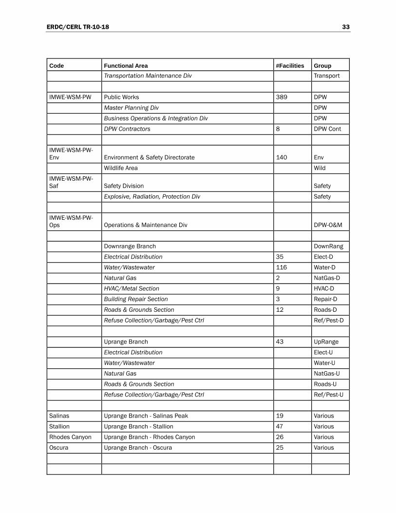
IMWE-WSM-PW Public Works 389 DPW
Master Planning Div DPW
Business Operations & Integration Div DPW
DPW Contractors 8 DPW Cont
IMWE-WSM-PW-Env Environment & Safety Directorate 140 Env
Wildlife Area Wild
IMWE-WSM-PW-Saf Safety Division Safety
Explosive, Radiation, Protection Div Safety
IMWE-WSM-PW-Ops Operations & Maintenance Div DPW-O&M
Downrange Branch DownRang
Electrical Distribution 35 Elect-D
Water/Wastewater 116 Water-D
Natural Gas 2 NatGas-D
HVAC/Metal Section 9 HVAC-D
Building Repair Section 3 Repair-D
Roads & Grounds Section 12 Roads-D
Refuse Collection/Garbage/Pest Ctrl Ref/Pest-D
Uprange Branch 43 UpRange
Electrical Distribution Elect-U
Water/Wastewater Water-U
Natural Gas NatGas-U
Roads & Grounds Section Roads-U
Refuse Collection/Garbage/Pest Ctrl Ref/Pest-U
Salinas Uprange Branch - Salinas Peak 19 Various
Stallion Uprange Branch - Stallion 47 Various
Rhodes Canyon Uprange Branch - Rhodes Canyon 26 Various
Oscura Uprange Branch - Oscura 25 Various
ERDC/CERL TR-10-18 34
Code Functional Area #Facilities Group Vacant 150 VacDem'd
Turn-in/Demo 210 VacDem'd
Orphans - Not Identified in RPI 1159 Orphans
TENANTS
Medical William Beaumont Medical Center MED
Medical McAfee U.S. Army Health Clinic 2 MED
Medical U.S. Army Dental Clinic MED
Medical Veterinary Clinic 5 VET
TEDT-WST-O Army Air Office 21 AAO
DODAFC DOD Area Frequency Coordinator 1 Command
CCM Center for Countermeasures (CCM) 1 CCM
ARL U.S. Army Research Laboratory-WSMR (AMSRD) 52 ARL
TMDE3 (CAL Lab) USA Test Measurement & Diagnostic Equip (TMDE Region 3) - (Cal Lab) 3 CAL
Navy Port Hueneme Div Naval Surface Warfare Center (PHD-NSWC) 33 PHD-NSWC
AF Deputy for Air Force White Sands Missile Range 5 DAF
AF - GEODDS Grnd Based Electro-Optical Deep Space Surveillance 4 DAF
AF - Lincoln Lab Lincoln Lab (MIT) 2 DAF
ACE Army Corps of Engineers 1 COE
USASDC U.S. Army Strategic Defense Commn (USASDC) USASDC
HELSTF High Energy Laser System Test Facility 72 USASDC
STRICOM STRICOM (Redstone Arsenal) 32 STRICOM
AAFES Army Air Force Exchange Service (AAFES) 5 AAFES
DECA Defense Commissary Agency (DECA) 1 DECA
NASA NASA 6 NASA
TRAC TRAC (DARPA research unit?) 4 TRAC
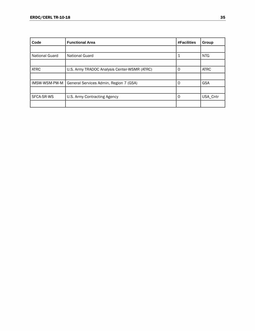
ERDC/CERL TR-10-18 35
Code Functional Area #Facilities Group
National Guard National Guard 1 NTG
ATRC U.S. Army TRADOC Analysis Center-WSMR (ATRC) 0 ATRC
IMSW-WSM-PW-M General Services Admin, Region 7 (GSA) 0 GSA
SFCA-SR-WS U.S. Army Contracting Agency 0 USA_Cntr
ERDC/CERL TR-10-18 36
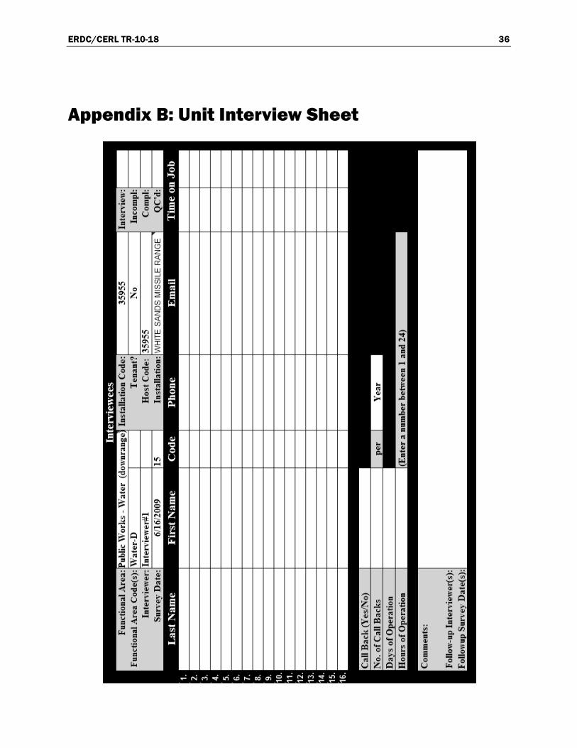
Appendix B: Unit Interview Sheet
ERDC/CERL TR-10-18 37
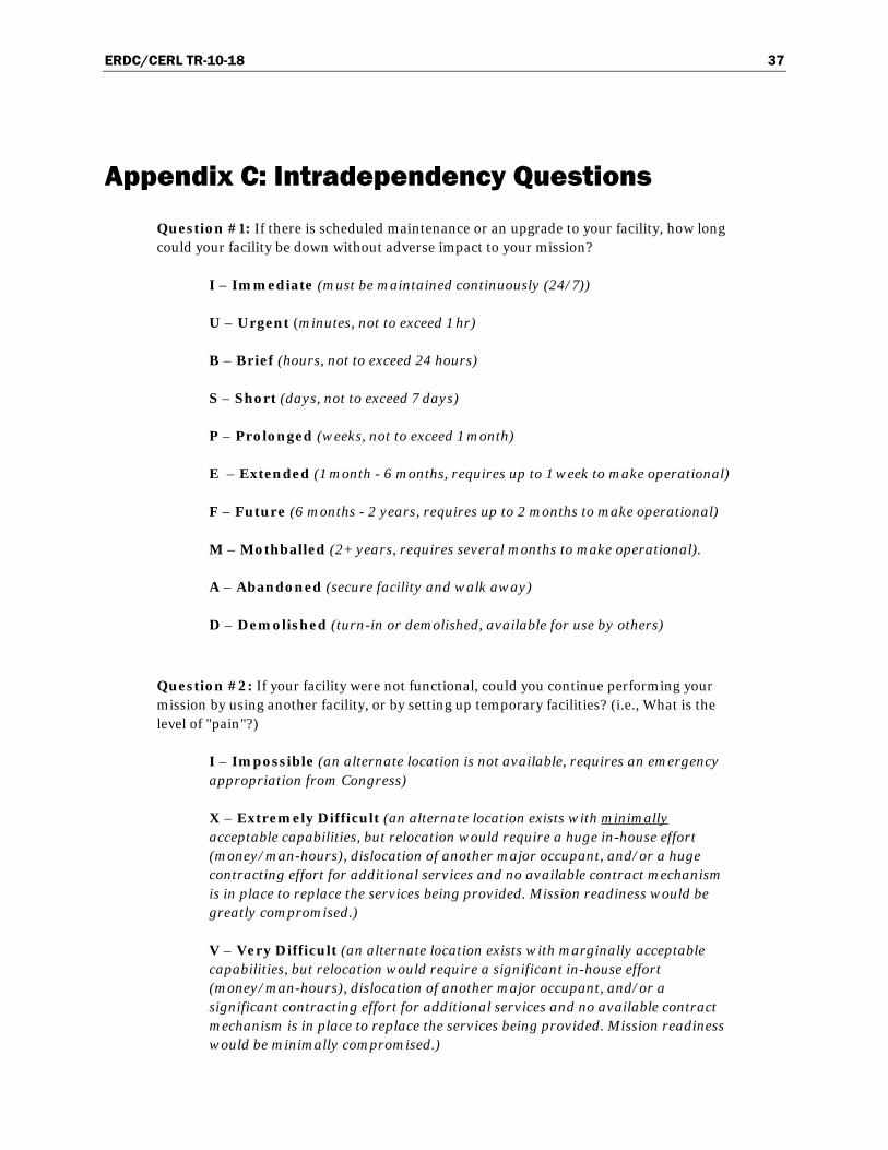
Appendix C: Intradependency Questions
Question #1: If there is scheduled maintenance or an upgrade to your facility, how long could your facility be down without adverse impact to your mission?
I – Immediate (must be maintained continuously (24/7))
U – Urgent (minutes, not to exceed 1 hr)
B – Brief (hours, not to exceed 24 hours)
S – Short (days, not to exceed 7 days)
P – Prolonged (weeks, not to exceed 1 month)
E – Extended (1 month - 6 months, requires up to 1 week to make operational)
F – Future (6 months - 2 years, requires up to 2 months to make operational)
M – Mothballed (2+ years, requires several months to make operational).
A – Abandoned (secure facility and walk away)
D – Demolished (turn-in or demolished, available for use by others)
Question #2: If your facility were not functional, could you continue performing your mission by using another facility, or by setting up temporary facilities? (i.e., What is the level of "pain"?)
I – Impossible (an alternate location is not available, requires an emergency appropriation from Congress)
X – Extremely Difficult (an alternate location exists with minimally acceptable capabilities, but relocation would require a huge in-house effort (money/man-hours), dislocation of another major occupant, and/or a huge contracting effort for additional services and no available contract mechanism is in place to replace the services being provided. Mission readiness would be greatly compromised.)
V – Very Difficult (an alternate location exists with marginally acceptable capabilities, but relocation would require a significant in-house effort (money/man-hours), dislocation of another major occupant, and/or a significant contracting effort for additional services and no available contract mechanism is in place to replace the services being provided. Mission readiness would be minimally compromised.)
ERDC/CERL TR-10-18 38
D – Difficult (an alternate location exists with acceptable capabilities and capacity but relocation would require a measurable and unbudgeted level of effort (money/man-hours), and mission readiness capabilities would not be compromised in the process.)
P – Possible (an alternate location is readily available with sufficient capabilities and capacity, in addition the level of effort has been budgeted for or can be easily absorbed)

ERDC/CERL TR-10-18 39
Appendix D: Interdependency Questions
Question #3: For each Functional Area that provides you services, how long could the services be interrupted before your mission readiness was negatively impacted, or else how long can you wait until they resolve your request?
N – None (any interruption will instantly impact mission readiness)
U – Urgent (minutes, not to exceed 1 hour)
B – Brief (hours, not to exceed 24 hours and there are insufficient redundancies built into the system to absorb a brief interruption)
S – Short (days, not to exceed 7 days, and there are sufficient and effective redundancies built into the system to cover brief interruptions)
P – Prolonged (weeks, not to exceed 1 month)
E – Extended (months, not to exceed 6 months)
F – Future (6 months – 2 years)
Question #4: If the Functional Area was not available, how difficult is it to replace or replicate the service? (What is the level of "pain"?)
I – Impossible (there are no known redundancies or excess/surge capacities available, or there are no viable commercial alternatives – only this site/command can provide these services)
X – Extremely Difficult (there are minimally acceptable redundancies or excess/surge capacities available, or there are limited commercial alternatives, and there are no readily available contract mechanisms in place to replace the services. Mission readiness is greatly compromised)
V – Very Difficult (there are marginally acceptable redundancies or excess/surge capacities available, or there are viable commercial alternatives, and there are contract mechanisms in place or can readily be put in place to replace the services. Mission readiness is minimally compromised.)
D – Difficult (services exist and are available, but the form of delivery is ill defined or will require a measurable and unbudgeted level of effort to obtain (money/man-hours). There is a contract mechanism in place to replace the services. Mission readiness capabilities would not be compromised in the process.)
P – Possible (services exist, are available, and are well defined)

REPORT DOCUMENTATION PAGE Form Approved OMB No. 0704-0188
Public reporting burden for this collection of information is estimated to average 1 hour per response, including the time for reviewing instructions, searching existing data sources, gathering and maintaining the data needed, and completing and reviewing this collection of information. Send comments regarding this burden estimate or any other aspect of this collection of information, including suggestions for reducing this burden to Department of Defense, Washington Headquarters Services, Directorate for Information Operations and Reports (0704-0188), 1215 Jefferson Davis Highway, Suite 1204, Arlington, VA 22202-4302. Respondents should be aware that notwithstanding any other provision of law, no person shall be subject to any penalty for failing to comply with a collection of information if it does not display a currently valid OMB control number. PLEASE DO NOT RETURN YOUR FORM TO THE ABOVE ADDRESS.
1. REPORT DATE (DD-MM-YYYY) September 2010
2. REPORT TYPE Final
3. DATES COVERED (From - To)
4. TITLE AND SUBTITLE Development of the Army Facility Mission Dependency Index for Infrastructure Asset Management
5a. CONTRACT NUMBER
5b. GRANT NUMBER
5c. PROGRAM ELEMENT NUMBER ITTP
6. AUTHOR(S) Michael N. Grussing, Steve Gunderson, Mary Canfield, Ed Falconer, Albert Antelman, and Samuel L. Hunter
5d. PROJECT NUMBER FY09-39
5e. TASK NUMBER
5f. WORK UNIT NUMBER
7. PERFORMING ORGANIZATION NAME(S) AND ADDRESS(ES) U.S. Army Engineer Research and Development Center Construction Engineering Research Laboratory P.O. Box 9005 Champaign, IL 61826-9005
8. PERFORMING ORGANIZATION REPORT NUMBER
ERDC/CERL TR-10-18
9. SPONSORING / MONITORING AGENCY NAME(S) AND ADDRESS(ES) Office of the Assistant Chief of Staff for Installation Management Facilities Branch (DAIM-ODF) 2511 Jefferson Davis Highway Arlington, VA 22202
10. SPONSOR/MONITOR’S ACRONYM(S) ACSIM
11. SPONSOR/MONITOR’S REPORT NUMBER(S)
12. DISTRIBUTION / AVAILABILITY STATEMENT Approved for public release; distribution is unlimited.
13. SUPPLEMENTARY NOTES
14. ABSTRACT This report describes a Mission Dependency Index (MDI) developed for U.S. Army facility asset management. The MDI is an indica-tor of mission-related importance of Army infrastructure elements to be used for the purpose of providing more effective local priori-tization of facilities for sustainment, restoration, and modernization (SRM) actions. It does this by evaluating the mission impact of interrupting a function or relocating where it is provided. The index is reported on a scale of 0–100, and is analogous in that respect with existing Corps of Engineers Sustainment Management System (SMS) indices. As part of this work, an MDI methodology direct-ly fit to Army-specific missions, facility resource capabilities, and organizational structure was developed. This was accomplished through a pilot implementation at White Sands Missile Range. The objectives of the demonstration were to identify Army-specific MDI criteria, develop a standardized implementation process, determine the steps for integrating MDI information into garrison-level and Army-level facility management business processes, and identify considerations and requirements for incorporating Army MDI criteria into the BUILDER® SMS. The results of an MDI analysis, as facilitated using the implementation and integration procedures recommended here, will enable facility decision makers to focus on infrastructure most critical to mission effectiveness.
15. SUBJECT TERMS asset management, Mission Dependency Index (MDI), Sustainment Management Systems (SMS), infrastructure, evaluation, Installa-tion Status Report for Infrastructure (ISR-I), mission criticality
16. SECURITY CLASSIFICATION OF: 17. LIMITATION OF ABSTRACT
18. NUMBER OF PAGES
19a. NAME OF RESPONSIBLE PERSON
a. REPORT
Unclassified
b. ABSTRACT
Unclassified
c. THIS PAGE
Unclassified 51 19b. TELEPHONE NUMBER (include area code)
Standard Form 298 (Rev. 8-98) Prescribed by ANSI Std. 239.18