erection and installation of stainless steel … inox publications/erection...erection and...
TRANSCRIPT
Building Series, Volume 10
Erection and Installation of Stainless Steel Components
E R E C T I O N A N D I N S T A L L A T I O N O F S T A I N L E S S S T E E L C O M P O N E N T S
Euro Inox
Euro Inox is the European market development associ-
ation for stainless steel.
Members of Euro Inox include:
• European stainless steel producers
• national stainless steel development associations
• development associations of the alloying element
industries.
The prime objectives of Euro Inox are to create aware-
ness of the unique properties of stainless steel and to
further its use in existing applications and in new mar-
kets. To achieve these objectives, Euro Inox organises
conferences and seminars, issues guidance in printed
and electronic form to enable architects, designers,
specifiers, fabricators and end users to become more
familiar with the material. Euro Inox also supports
technical and market research.
Copyright notice
This work is subject to copyright. Euro Inox reserves
all rights of translation in any language, reprinting,
re-use of illustrations, recitations and broadcasting.
No part of this publication may be reproduced, stored
in a retrieval system, or transmitted in any form or by
any means, electronic, mechanical, photocopying,
recording or otherwise, without the prior written per-
mission of the copyright owner, Euro-Inox, Luxem-
bourg. Violations may be subject to legal proceeding
and liable for monetary damages per infringement as
well as cost and legal fees and fall under prosecution
act of the Luxemburg copyright law and regulations
within the European Union.
Full members
Acerinox
www.acerinox.es
Outokumpu
www.outokumpu.com
ThyssenKrupp Acciai Speciali Terni
www.acciaiterni.it
ThyssenKrupp Nirosta
www.nirosta.de
UGINE & ALZ Belgium
UGINE & ALZ France
Groupe Arcelor
www.ugine-alz.com
Associate members
Acroni
www.acroni.si
British Stainless Steel Association (BSSA)
www.bssa.org.uk
Cedinox
www.cedinox.es
Centro Inox
www.centroinox.it
Informationsstelle Edelstahl Rostfrei
www.edelstahl-rostfrei.de
Institut de Développement de l’Inox
(I.D.-Inox)
www.idinox.com
International Chromium Development Association (ICDA)
www.icdachromium.com
International Molybdenum Association (IMOA)
www.imoa.info
Nickel Institute
www.nickelinstitute.org
Polska Unia Dystrybutorów Stali (PUDS)
www.puds.com.pl
SWISSINOX
Informationsstelle für nichtrostende Stähle
www.swissinox.chISBN 2-87997-143-8
E R E C T I O N A N D I N S T A L L A T I O N O F S T A I N L E S S S T E E L C O M P O N E N T S
Erection and Installation of Stainless Steel Components
First Edition 2006
(Building Series, Volume 10)
© Euro Inox 2006
Publisher
Euro Inox
Registered office:
241 route d’Arlon
1150 Luxembourg, Grand Duchy of Luxembourg
Phone: +352 26 10 30 50 / Fax: + 352 26 10 30 51
Executive office:
Diamant Building, Bd. A. Reyers 80
1030 Brussels, Belgium
Tel.: +32 2 706 82 67 / Fax: +32 2 706 82 69
E-mail: [email protected]
Internet: www.euro-inox.org
Author
Nancy Baddoo, The Steel Construction Institute,
Ascot, UK
Disclaimer
Euro Inox and The Steel Construction Institute have
made every effort to ensure that the information pres-
ented in this document is technically correct.
However, the reader is advised that the material con-
tained herein is for general information purposes
only. Euro Inox, its members, specifically disclaim any
liability or responsibility for loss, damage, or injury,
resulting from the use of the information contained in
this publication.
1
Contents
1 Introduction 2
2 Site conditions 3
3 Erection planning 4
3.1 General 4
3.2 Erection method statement 4
3.3 Trial erection 4
4 Supports, anchors and bearings 5
5 Erection drawings 6
6 Tolerances 6
7 Transportation, handling and storage 7
7.1 General 7
7.2 Transportation 7
7.3 Handling 7
7.4 Storage 9
7.5 Marking 11
8 Erection methods 12
9 Site welding 13
10 Surface protection 13
11 Cleaning before handover 15
12 Dissimilar metal contact 17
13 Cladding installation 20
13.1 Surface consistency 20
13.2 Flatness 20
13.3 Cleanliness 21
14 Fasteners 22
15 References
Photo credits
Cedinox, Madrid (E), p. 23
Centro Inox, Milan (I) p. 19
Niton, Billerica, MA (USA) , p. 10
NTD, Concorezzo (I), p. 10
T. Pauly, Brussels (B), cover, p. 2, 6, 13, 14, 20, 21, 23
V. Röyttä, Tornio (FIN) , p. 8
Stelos Oy, Helsinki (FIN), p. 4, 12
The Steel Construction Institute, Ascot (UK) p. 18
Ugine & ALZ Belgium, Genk (B) p. 20
B. Van Hecke, Brussels (B), p. 9, 11, 14, 15, 16
2
E R E C T I O N A N D I N S T A L L A T I O N O F S T A I N L E S S S T E E L C O M P O N E N T S
1 Introduction
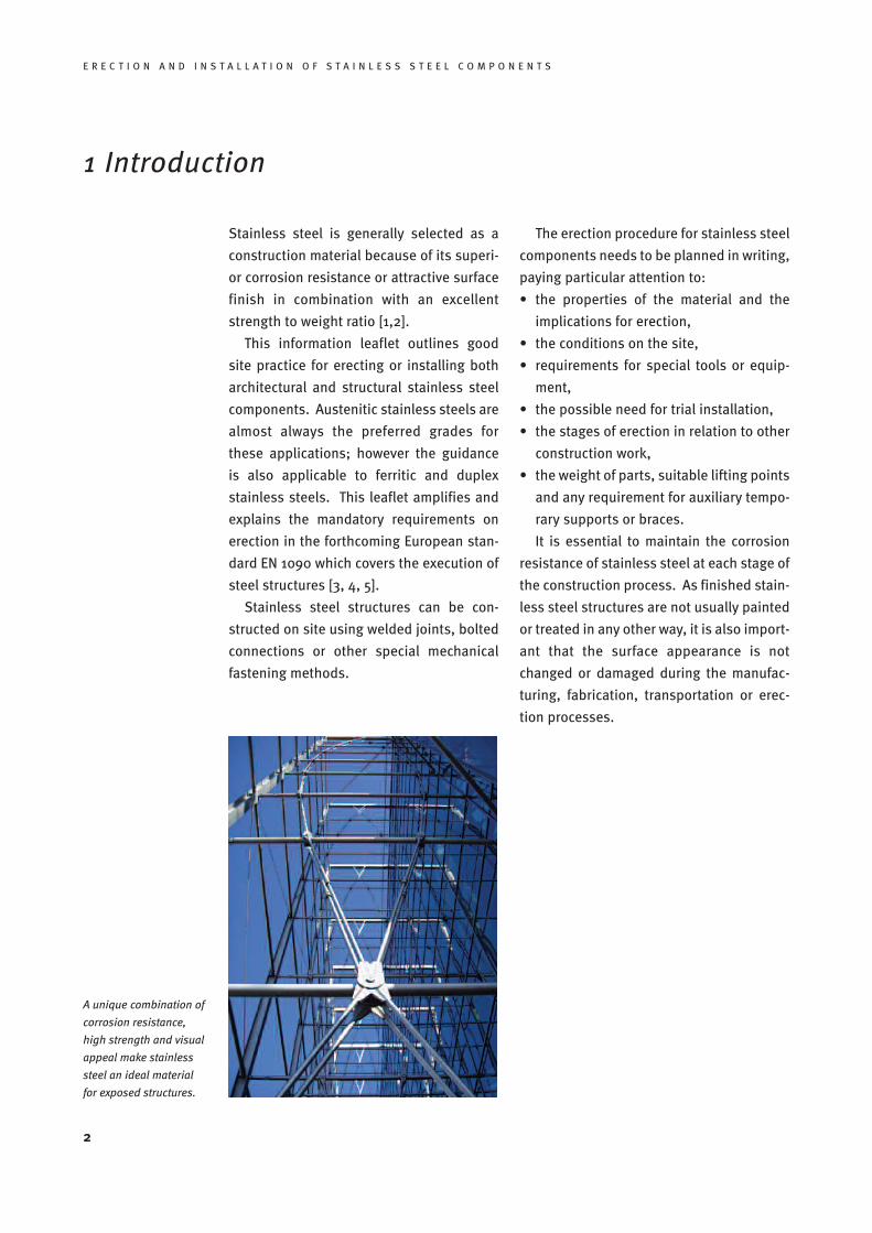
A unique combination of
corrosion resistance,
high strength and visual
appeal make stainless
steel an ideal material
for exposed structures.
Stainless steel is generally selected as a
construction material because of its superi-
or corrosion resistance or attractive surface
finish in combination with an excellent
strength to weight ratio [1,2].
This information leaflet outlines good
site practice for erecting or installing both
architectural and structural stainless steel
components. Austenitic stainless steels are
almost always the preferred grades for
these applications; however the guidance
is also applicable to ferritic and duplex
stainless steels. This leaflet amplifies and
explains the mandatory requirements on
erection in the forthcoming European stan-
dard EN 1090 which covers the execution of
steel structures [3, 4, 5].
Stainless steel structures can be con-
structed on site using welded joints, bolted
connections or other special mechanical
fastening methods.
The erection procedure for stainless steel
components needs to be planned in writing,
paying particular attention to:
• the properties of the material and the
implications for erection,
• the conditions on the site,
• requirements for special tools or equip-
ment,
• the possible need for trial installation,
• the stages of erection in relation to other
construction work,
• the weight of parts, suitable lifting points
and any requirement for auxiliary tempo-
rary supports or braces.
It is essential to maintain the corrosion
resistance of stainless steel at each stage of
the construction process. As finished stain-
less steel structures are not usually painted
or treated in any other way, it is also import-
ant that the surface appearance is not
changed or damaged during the manufac-
turing, fabrication, transportation or erec-
tion processes.
E R E C T I O N A N D I N S T A L L A T I O N O F S T A I N L E S S S T E E L C O M P O N E N T S
2 Site conditions
Erection should only start when the con-
struction site meets certain safety require-
ments. Relevant issues which need to be
considered include:
• adequate access to the site and within the
site,
• provision and maintenance of hard stand-
ing for cranes and access equipment,
• limitations on dimensions or weights of
components that can be delivered onto
the site,
• details of adjacent structures which may
affect the erection process.
3
3 Erection planning
3.1 General
The principal safety objectives when erect-
ing steelwork are:
• stability of the part-erected structure;
• safe lifting and placing of steel compon-
ents; and
• safe access and working positions.
The particular differences that arise when
erecting or installing stainless steel compo-
nents are:
• the greater relative flexibility of stainless
steel components (especially architectur-
al panels) that may have an effect on the
stiffness of the part-erected structure;
• the need to ensure that components with
architecturally-important finishes are not
damaged during lifting and placing; and
• the need to provide safe access and work-
ing positions for suitably-timed site activ-
ities that do not generally occur unless
there are requirements for architectural
appearance (e.g. polishing and cleaning).
The principal means for ensuring that these
specialist issues are properly addressed is
to select contractors and site operatives who
have experience of and training in the erec-
tion and installation of stainless steel com-
ponents. Only by using suitably competent
persons can safety and performance be
assured.
In addition, the particular requirements of
the project will need to be specifically
addressed, both in preparing the erection
method statement (see below), and in the
briefing of the site team.
Full briefing of the site team on a regular
basis, using the method statement, will
ensure that they...
• understand what has to be done
• are provided with the necessary tools and
equipment; and
• are given suitable methods and personal
protective equipment to deal with safety
hazards (such as the likelihood of sharp
cut edges).
4
E R E C T I O N A N D I N S T A L L A T I O N O F S T A I N L E S S S T E E L C O M P O N E N T S
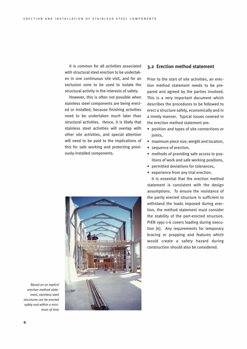
Based on an explicit
erection method state-
ment, stainless steel
structures can be erected
safely and within a mini-
mum of time
It is common for all activities associated
with structural steel erection to be undertak-
en in one continuous site visit, and for an
exclusion zone to be used to isolate the
structural activity in the interests of safety.
However, this is often not possible when
stainless steel components are being erect-
ed or installed, because finishing activities
need to be undertaken much later than
structural activities. Hence, it is likely that
stainless steel activities will overlap with
other site activities, and special attention
will need to be paid to the implications of
this for safe working and protecting previ-
ously-installed components.
3.2 Erection method statement
Prior to the start of site activities, an erec-
tion method statement needs to be pre-
pared and agreed by the parties involved.
This is a very important document which
describes the procedures to be followed to
erect a structure safely, economically and in
a timely manner. Typical issues covered in
the erection method statement are:
• position and types of site connections or
joints,
• maximum piece size, weight and location,
• sequence of erection,
• methods of providing safe access to pos-
itions of work and safe working positions,
• permitted deviations for tolerances,
• experience from any trial erection.
It is essential that the erection method
statement is consistent with the design
assumptions. To ensure the resistance of
the partly erected structure is sufficient to
withstand the loads imposed during erec-
tion, the method statement must consider
the stability of the part-erected structure.
PrEN 1991-1-6 covers loading during execu-
tion [6]. Any requirements for temporary
bracing or propping and features which
would create a safety hazard during
construction should also be considered.
E R E C T I O N A N D I N S T A L L A T I O N O F S T A I N L E S S S T E E L C O M P O N E N T S
3.3 Trial erection
For expensive components that are difficult
to replace at short notice and may be rela-
tively easily damaged, it is more necessary
than normal to ensure that site activities
will take place exactly as planned. In such
circumstances, the use of full or partial trial
erection may offer the following benefits:
• the ability to inspect assembled units for
acceptability
• the ability to check the sequence of erec-
tion proposed for safety (particularly if
there are concerns about stability or
access provision)
• the possibility of measuring the duration
of operations (relevant if site conditions
are restricted by limited possession
time).
Experience from trial erection can then
be fed back to improve the erection method
statement. Trials can also be used to check
transportation, handling and storage meth-
ods to pre-empt the possibility of damage
occurring in transit.
5
4 Supports, anchors and bearings
The conditions, location and level of the sup-
ports for the steelwork should be suitably
prepared to receive the stainless steel com-
ponents. Erection should not begin until the
location and levels of the supports, anchors
or bearings comply with the acceptance cri-
teria agreed or specified.
Shims and other supporting devices used
as temporary supports under base plates
should present a flat surface to the steel-
work and be of adequate size, strength and
rigidity to avoid local crushing of the con-
crete. If packings are left in position after
grouting they need to be made from mater-
ials with the same durability as the struc-
ture. Note that grouting materials in contact
with stainless steel should not contain
chlorides.
6
E R E C T I O N A N D I N S T A L L A T I O N O F S T A I N L E S S S T E E L C O M P O N E N T S
5 Erection drawings
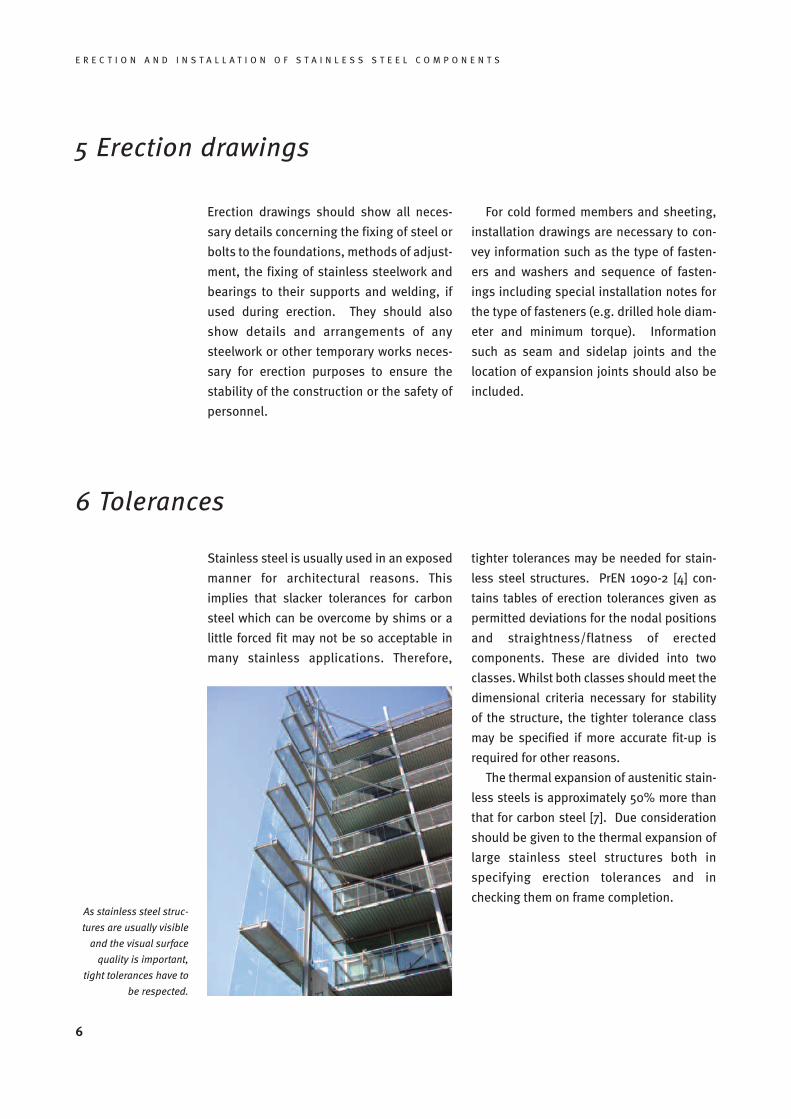
As stainless steel struc-
tures are usually visible
and the visual surface
quality is important,
tight tolerances have to
be respected.
Erection drawings should show all neces-
sary details concerning the fixing of steel or
bolts to the foundations, methods of adjust-
ment, the fixing of stainless steelwork and
bearings to their supports and welding, if
used during erection. They should also
show details and arrangements of any
steelwork or other temporary works neces-
sary for erection purposes to ensure the
stability of the construction or the safety of
personnel.
For cold formed members and sheeting,
installation drawings are necessary to con-
vey information such as the type of fasten-
ers and washers and sequence of fasten-
ings including special installation notes for
the type of fasteners (e.g. drilled hole diam-
eter and minimum torque). Information
such as seam and sidelap joints and the
location of expansion joints should also be
included.
6 Tolerances
Stainless steel is usually used in an exposed
manner for architectural reasons. This
implies that slacker tolerances for carbon
steel which can be overcome by shims or a
little forced fit may not be so acceptable in
many stainless applications. Therefore,
tighter tolerances may be needed for stain-
less steel structures. PrEN 1090-2 [4] con-
tains tables of erection tolerances given as
permitted deviations for the nodal positions
and straightness/flatness of erected
components. These are divided into two
classes. Whilst both classes should meet the
dimensional criteria necessary for stability
of the structure, the tighter tolerance class
may be specified if more accurate fit-up is
required for other reasons.
The thermal expansion of austenitic stain-
less steels is approximately 50% more than
that for carbon steel [7]. Due consideration
should be given to the thermal expansion of
large stainless steel structures both in
specifying erection tolerances and in
checking them on frame completion.
E R E C T I O N A N D I N S T A L L A T I O N O F S T A I N L E S S S T E E L C O M P O N E N T S
7 Transportation, handling and storage
7.1 General
Stainless steel components should be
accompanied by accurate instructions for
storage, handling and installation in order
to maintain the surface quality. This is par-
ticularly important for bright annealed, pol-
ished, textured and coloured or painted fin-
ishes. At all stages of fabrication, trans-
portation, handling, storage on site and
erection, it is necessary to avoid contamin-
ation of the surface of stainless steel com-
ponents by carbon steel and iron. This is to
prevent carbon steel pick-up, which may
subsequently rust and stain the surface.
Measures must be taken to prevent such
contamination due to contact with carbon
steel. Also, if work of a fabrication nature
needs to be undertaken on site, it will be
necessary to use quarantined work areas,
tools which are dedicated only to stainless
steel, and stainless steel wire brushes or
wool, and to avoid using carbon steel lifting
tackle and unprotected forks of fork lift
trucks. Other potentially harmful contam-
inants include oils, greases and weld spat-
ter.
The use of strippable plastic film coat-
ings on the stainless steels can help to
avoid surface contamination (Section 10). If
the stainless steel has a protective film, it
should be left on as long as practicable and
removed just before handover [8].
7.2 Transportation
Special packaging measures may be need-
ed for protecting stainless steel compon-
ents in transit in order to protect the sur-
face. For example, care is needed when
components are being secured to pallets or
vehicles for transport to avoid damage to
surfaces from straps or strapping. Suitable
protective materials should be placed
between the stainless steel and the secur-
ing straps. If carbon steel strapping is to be
used to secure items to pallets or in bun-
dles, some form of wrapping or padding is
required to prevent the strapping from dam-
aging the edges or surface of the stainless
steel components.
Corrosion damage may occur if moisture
condenses on surfaces under plastic pack-
aging (particularly heat shrink wrappings)
during transport. This is more likely to hap-
pen if the packaging remains in place for a
long time and if the conditions are humid,
especially if an item is to be shipped in a
humid or salt-laden environment. Suitable
desiccants packed within the packaging can
help alleviate the moisture problem. After
delivery the stainless steel should be
inspected to identify any surface defects
that require correction.
7.3 Handling
Stainless steel components should be han-
dled and stacked in such a way that the like-
lihood of damage is minimized. Care is ne-
cessary during all handling and lifting oper-
ations to ensure that the stainless steel is
not mechanically damaged. If chain slings
are used, these inevitably tend to slip, caus-
ing mechanical damage of the surface.
Slings of heavy duty synthetic material are
preferable and may reduce the risk of cross-
contamination.
7
8
E R E C T I O N A N D I N S T A L L A T I O N O F S T A I N L E S S S T E E L C O M P O N E N T S
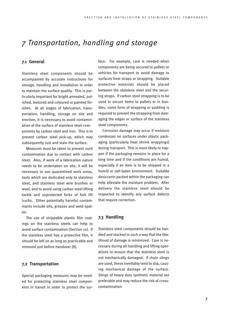
Plastic slings on the lift-
ing gear and film protec-
tion of the stainless steel
components prevent fer-
rous contamination and
mechanical damage
Steel components damaged during off-
loading, transportation, storage or erection
need to be restored to conformity. For stain-
less steel components, it may prove difficult
to undertake the specialist correction work
necessary on site, thus necessitating the
return of the damaged component to the
fabrication works, or even its replacement.
Hence, the emphasis is on using sound han-
dling methods to minimise the likelihood of
damage in transit.
Thin gauge cold formed components and
sheeting may be particularly prone to edge
damage, twisting or distortion if handled as
individual items. Hence they are often best
packaged into bundles for transit, as nested
components are likely to be more robust.
However, care should be taken to avoid
localized damage to unstiffened edges at
lifting points or other zones where the total
weight of the bundle is imposed on a single
unreinforced edge.
Completed stainless steel members are
likely to be slender increasing the likeli-
hood of localised damage from single point
lifting of long components. As is common-
place with comparable carbon steel struc-
tures, consideration should be given to the
use of spreader beams and additional tem-
porary stiffening devices to maintain indi-
vidual member stability during lifting.
Sleeved slings will assist, but dedicated lift-
ing points integrated into the structure are
a better solution.
All handling equipment should be
cleaned shortly prior to its use with stain-
less steel components. It is therefore advis-
able to plan and schedule the handling of
stainless steel components because, if han-
dling equipment is used on an uncontrolled
basis, this cleaning is often neglected and
contamination results.
Stainless steel should be protected from
direct contact with carbon steel lifting tackle
or handling equipment such as chains,
hooks, strapping and rollers or the forks of
fork lift trucks by the use of isolating mater-
ials such as light plywood or suction cups.
These requirements should be developed
into work instructions for site lifting oper-
ations that can be appended to the erection
method statement, and used to brief the
site team.
Contact with chemicals, including dyes,
glues, adhesive tape, undue amounts of oil
and grease should be avoided. If it is neces-
sary to use them, their suitability should be
either checked with their manufacturer, or
tested by applying them to a trial piece of
equivalent stainless steel.
There can be certain health hazards in
lifting stainless steel components in that
the cut edges may be rather sharp. If this
hazard cannot be avoided by protecting the
cut edges, it should be identified when the
erection and handling methods are devel-
oped and suitable protective equipment
issued to site personnel.
E R E C T I O N A N D I N S T A L L A T I O N O F S T A I N L E S S S T E E L C O M P O N E N T S
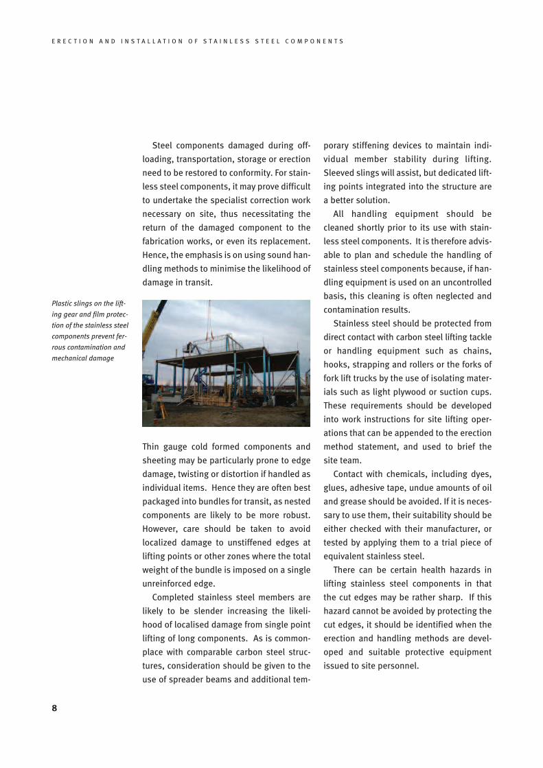
The plastic packaging
protects the stainless
steel hollow sections
against iron pickup from
carbon steel racks.
7.4 Storage
Stainless steel components need to be
stored suitably carefully, so that the sur-
faces are protected from damage or con-
tamination. Dry storage under cover is
preferable, particularly if a wrapping which
might absorb water and stain the surface,
such as cardboard, has been used. It is
preferable for planar-shaped components
made from sheet or plate to be stored
upright in racks. If storage racks are used,
they should be protected by wooden, rub-
ber or plastic battens or sheaths to avoid
carbon steel, copper-containing or lead rub-
bing surfaces.
Long periods in salt-laden or other
aggressive environment can seriously
impair the passive film on lower grade
stainless alloys such as grade 1.4301 (304).
Hence, a limitation should be set for the
storage period in such atmospheres for
lower grade alloys.
Fasteners stored on site should be kept
in dry conditions, suitably packed and iden-
tifiable.
The storage areas should be secure
against theft as stainless steel is a valuable
material and can be costly to repair or
replace.
The table overleaf describes four indica-
tors which can be used to distinguish
between stainless steel and other metals on
site. Chemical and electrochemical test kits
can be used for distinguishing between
molybdenum-containing grades like 1.4401
and non-molybdenum-containing grades
like 1.4301. Also hand-held X-ray devices
are available, which analyse the chemical
composition of metallic materials.
9
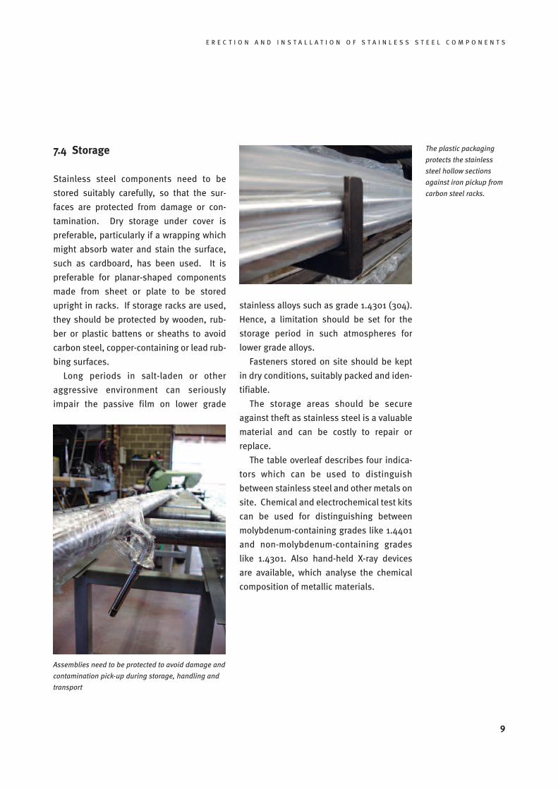
Assemblies need to be protected to avoid damage and
contamination pick-up during storage, handling and
transport
10
E R E C T I O N A N D I N S T A L L A T I O N O F S T A I N L E S S S T E E L C O M P O N E N T S
Distinguishing between stainlesssteel and other metals on site
Colour
Stainless steel and carbon steel can be of
similar colour, for example when freshly
machined, cut or abraded and, in such
conditions, are difficult for the untrained
eye to tell apart.
Density
There is very little difference between the
densities of stainless steels and carbon
steels. Aluminium alloys are about one
third the density of steels.
Magnetism
Ferritic and duplex grades of stainless
steel are magnetic. Austenitic grades of
stainless steel in the annealed (softened)
state are not magnetic, though they have
a tendency to exhibit some magnetic
properties when they are cold worked.
The partial magnetic attraction exhibited
by components with complex shapes is
usually non-uniform, and is more marked
at formed corners or near drilled holes or
machined faces. This uneven distribution
is often useful in confirming the steel as
an austenitic type because this variation
in attraction to a magnet does not occur
with other stainless steels, carbon steels
or metals like aluminium.
Corrosion resistance
A large drop of tap water left on a steel
surface overnight will normally produce
rust staining on a carbon or low alloy
steel, but not on stainless steel.
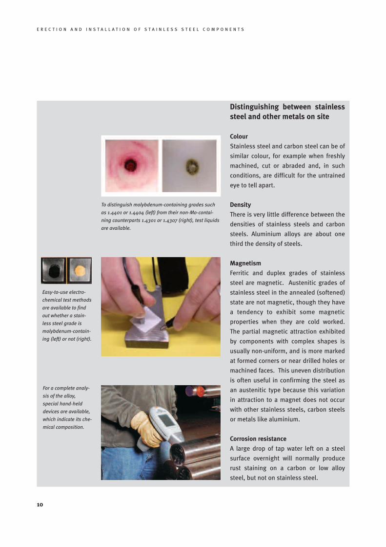
To distinguish molybdenum-containing grades such
as 1.4401 or 1.4404 (left) from their non-Mo-contai-
ning counterparts 1.4301 or 1.4307 (right), test liquids
are available.
Easy-to-use electro-
chemical test methods
are available to find
out whether a stain-
less steel grade is
molybdenum-contain-
ing (left) or not (right).
For a complete analy-
sis of the alloy,
special hand-held
devices are available,
which indicate its che-
mical composition.
E R E C T I O N A N D I N S T A L L A T I O N O F S T A I N L E S S S T E E L C O M P O N E N T S
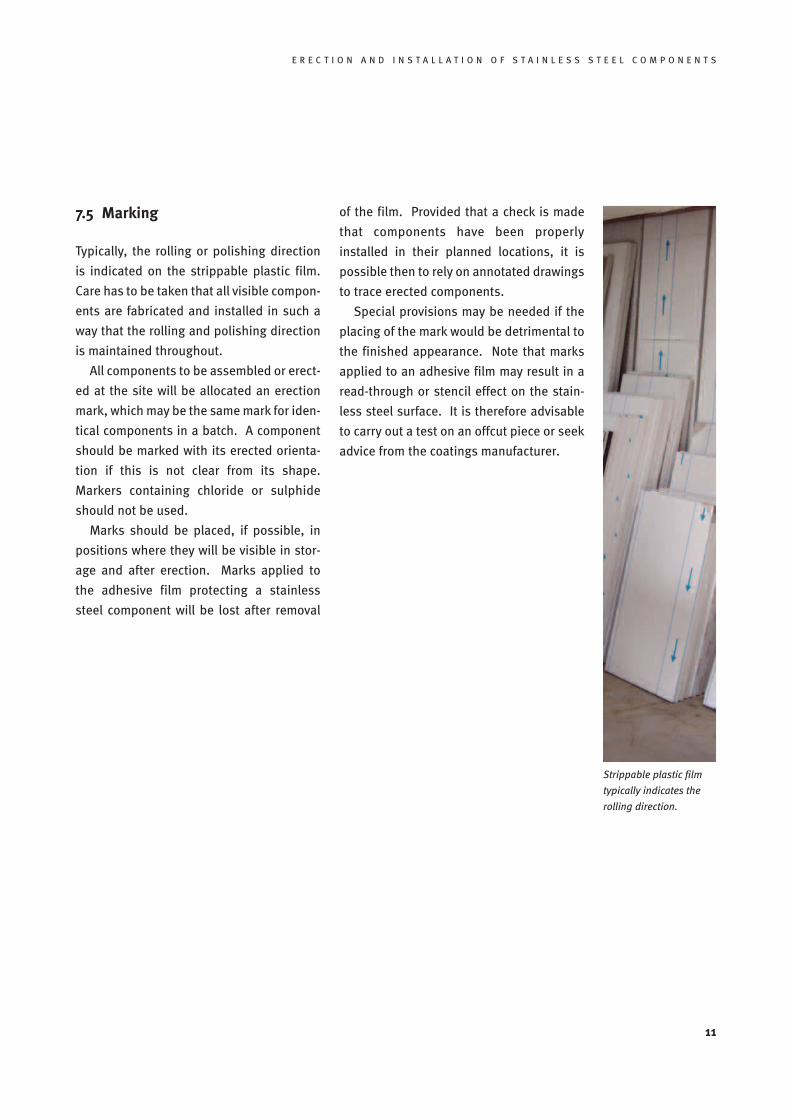
Strippable plastic film
typically indicates the
rolling direction.
7.5 Marking
Typically, the rolling or polishing direction
is indicated on the strippable plastic film.
Care has to be taken that all visible compon-
ents are fabricated and installed in such a
way that the rolling and polishing direction
is maintained throughout.
All components to be assembled or erect-
ed at the site will be allocated an erection
mark, which may be the same mark for iden-
tical components in a batch. A component
should be marked with its erected orienta-
tion if this is not clear from its shape.
Markers containing chloride or sulphide
should not be used.
Marks should be placed, if possible, in
positions where they will be visible in stor-
age and after erection. Marks applied to
the adhesive film protecting a stainless
steel component will be lost after removal
of the film. Provided that a check is made
that components have been properly
installed in their planned locations, it is
possible then to rely on annotated drawings
to trace erected components.
Special provisions may be needed if the
placing of the mark would be detrimental to
the finished appearance. Note that marks
applied to an adhesive film may result in a
read-through or stencil effect on the stain-
less steel surface. It is therefore advisable
to carry out a test on an offcut piece or seek
advice from the coatings manufacturer.
11
12
E R E C T I O N A N D I N S T A L L A T I O N O F S T A I N L E S S S T E E L C O M P O N E N T S
8 Erection methods
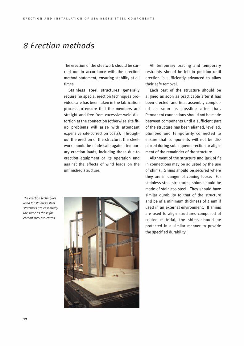
The erection techniques
used for stainless steel
structures are essentially
the same as those for
carbon steel structures
The erection of the steelwork should be car-
ried out in accordance with the erection
method statement, ensuring stability at all
times.
Stainless steel structures generally
require no special erection techniques pro-
vided care has been taken in the fabrication
process to ensure that the members are
straight and free from excessive weld dis-
tortion at the connection (otherwise site fit-
up problems will arise with attendant
expensive site-correction costs). Through-
out the erection of the structure, the steel-
work should be made safe against tempor-
ary erection loads, including those due to
erection equipment or its operation and
against the effects of wind loads on the
unfinished structure.
All temporary bracing and temporary
restraints should be left in position until
erection is sufficiently advanced to allow
their safe removal.
Each part of the structure should be
aligned as soon as practicable after it has
been erected, and final assembly complet-
ed as soon as possible after that.
Permanent connections should not be made
between components until a sufficient part
of the structure has been aligned, levelled,
plumbed and temporarily connected to
ensure that components will not be dis-
placed during subsequent erection or align-
ment of the remainder of the structure.
Alignment of the structure and lack of fit
in connections may be adjusted by the use
of shims. Shims should be secured where
they are in danger of coming loose. For
stainless steel structures, shims should be
made of stainless steel. They should have
similar durability to that of the structure
and be of a minimum thickness of 2 mm if
used in an external environment. If shims
are used to align structures composed of
coated material, the shims should be
protected in a similar manner to provide
the specified durability.
E R E C T I O N A N D I N S T A L L A T I O N O F S T A I N L E S S S T E E L C O M P O N E N T S
9 Site welding
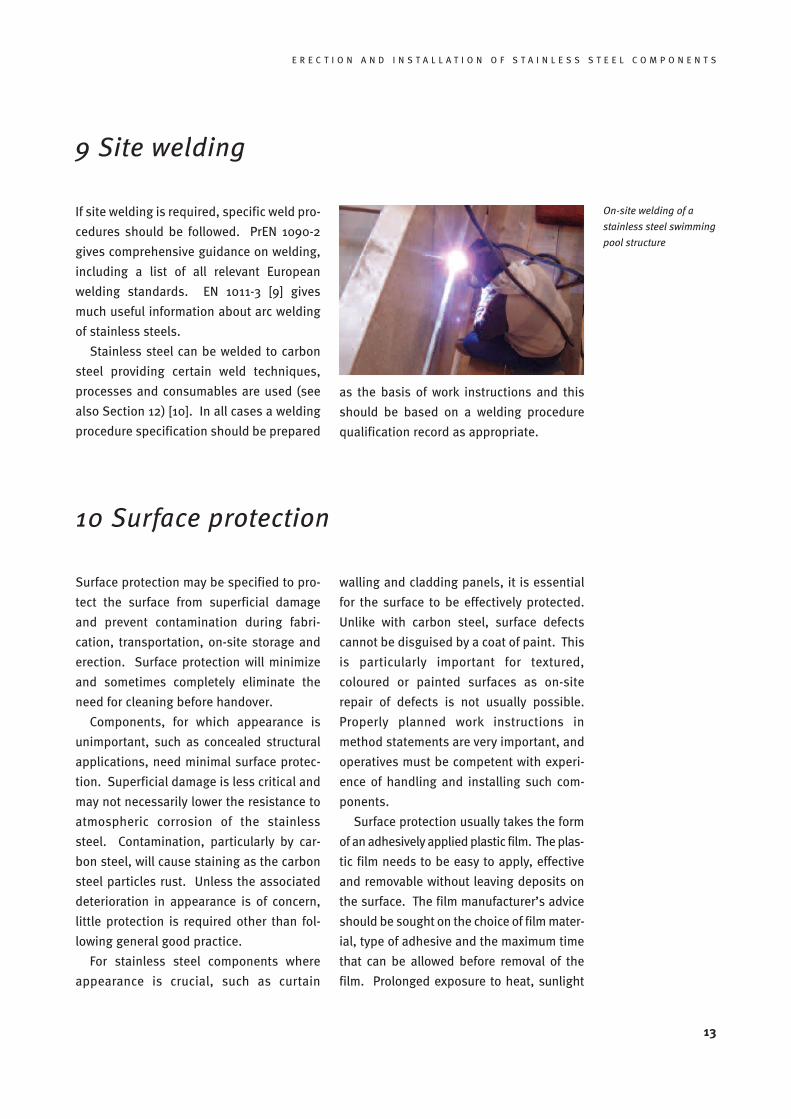
On-site welding of a
stainless steel swimming
pool structure
If site welding is required, specific weld pro-
cedures should be followed. PrEN 1090-2
gives comprehensive guidance on welding,
including a list of all relevant European
welding standards. EN 1011-3 [9] gives
much useful information about arc welding
of stainless steels.
Stainless steel can be welded to carbon
steel providing certain weld techniques,
processes and consumables are used (see
also Section 12) [10]. In all cases a welding
procedure specification should be prepared
as the basis of work instructions and this
should be based on a welding procedure
qualification record as appropriate.
13
10 Surface protection
Surface protection may be specified to pro-
tect the surface from superficial damage
and prevent contamination during fabri-
cation, transportation, on-site storage and
erection. Surface protection will minimize
and sometimes completely eliminate the
need for cleaning before handover.
Components, for which appearance is
unimportant, such as concealed structural
applications, need minimal surface protec-
tion. Superficial damage is less critical and
may not necessarily lower the resistance to
atmospheric corrosion of the stainless
steel. Contamination, particularly by car-
bon steel, will cause staining as the carbon
steel particles rust. Unless the associated
deterioration in appearance is of concern,
little protection is required other than fol-
lowing general good practice.
For stainless steel components where
appearance is crucial, such as curtain
walling and cladding panels, it is essential
for the surface to be effectively protected.
Unlike with carbon steel, surface defects
cannot be disguised by a coat of paint. This
is particularly important for textured,
coloured or painted surfaces as on-site
repair of defects is not usually possible.
Properly planned work instructions in
method statements are very important, and
operatives must be competent with experi-
ence of handling and installing such com-
ponents.
Surface protection usually takes the form
of an adhesively applied plastic film. The plas-
tic film needs to be easy to apply, effective
and removable without leaving deposits on
the surface. The film manufacturer’s advice
should be sought on the choice of film mater-
ial, type of adhesive and the maximum time
that can be allowed before removal of the
film. Prolonged exposure to heat, sunlight
14
E R E C T I O N A N D I N S T A L L A T I O N O F S T A I N L E S S S T E E L C O M P O N E N T S
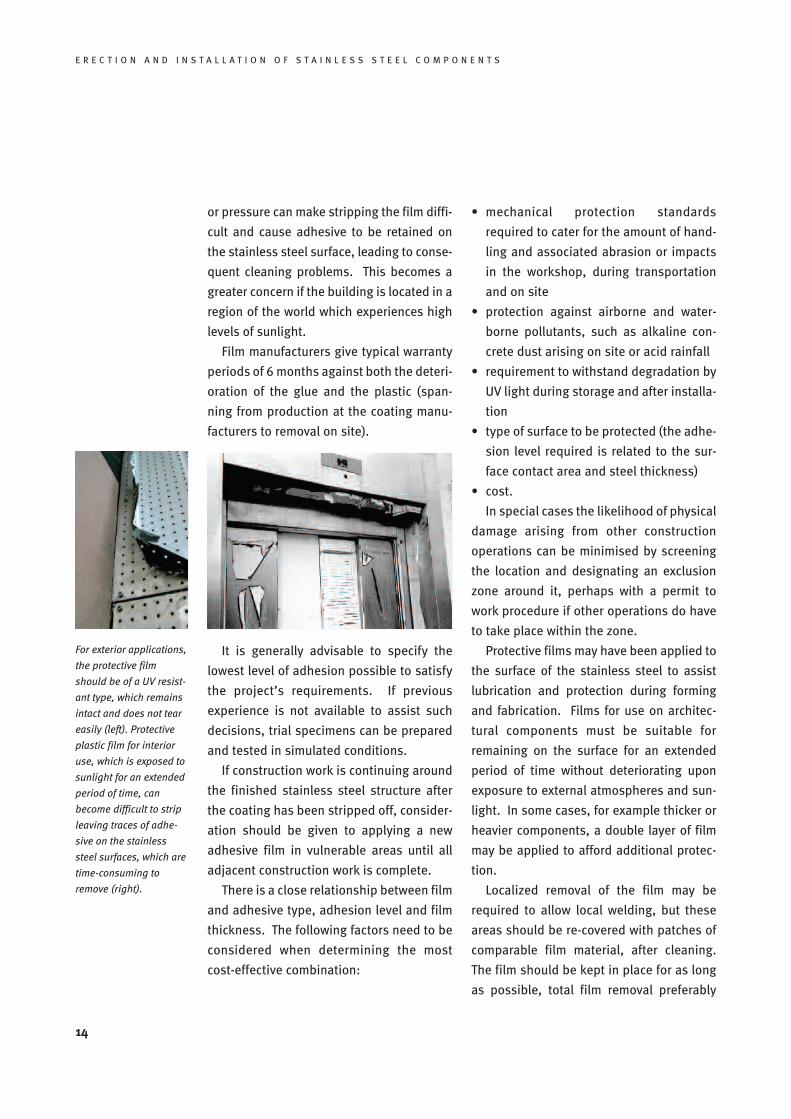
For exterior applications,
the protective film
should be of a UV resist-
ant type, which remains
intact and does not tear
easily (left). Protective
plastic film for interior
use, which is exposed to
sunlight for an extended
period of time, can
become difficult to strip
leaving traces of adhe-
sive on the stainless
steel surfaces, which are
time-consuming to
remove (right).
or pressure can make stripping the film diffi-
cult and cause adhesive to be retained on
the stainless steel surface, leading to conse-
quent cleaning problems. This becomes a
greater concern if the building is located in a
region of the world which experiences high
levels of sunlight.
Film manufacturers give typical warranty
periods of 6 months against both the deteri-
oration of the glue and the plastic (span-
ning from production at the coating manu-
facturers to removal on site).
It is generally advisable to specify the
lowest level of adhesion possible to satisfy
the project’s requirements. If previous
experience is not available to assist such
decisions, trial specimens can be prepared
and tested in simulated conditions.
If construction work is continuing around
the finished stainless steel structure after
the coating has been stripped off, consider-
ation should be given to applying a new
adhesive film in vulnerable areas until all
adjacent construction work is complete.
There is a close relationship between film
and adhesive type, adhesion level and film
thickness. The following factors need to be
considered when determining the most
cost-effective combination:
• mechanical protection standards
required to cater for the amount of hand-
ling and associated abrasion or impacts
in the workshop, during transportation
and on site
• protection against airborne and water-
borne pollutants, such as alkaline con-
crete dust arising on site or acid rainfall
• requirement to withstand degradation by
UV light during storage and after installa-
tion
• type of surface to be protected (the adhe-
sion level required is related to the sur-
face contact area and steel thickness)
• cost.
In special cases the likelihood of physical
damage arising from other construction
operations can be minimised by screening
the location and designating an exclusion
zone around it, perhaps with a permit to
work procedure if other operations do have
to take place within the zone.
Protective films may have been applied to
the surface of the stainless steel to assist
lubrication and protection during forming
and fabrication. Films for use on architec-
tural components must be suitable for
remaining on the surface for an extended
period of time without deteriorating upon
exposure to external atmospheres and sun-
light. In some cases, for example thicker or
heavier components, a double layer of film
may be applied to afford additional protec-
tion.
Localized removal of the film may be
required to allow local welding, but these
areas should be re-covered with patches of
comparable film material, after cleaning.
The film should be kept in place for as long
as possible, total film removal preferably
E R E C T I O N A N D I N S T A L L A T I O N O F S T A I N L E S S S T E E L C O M P O N E N T S
11 Cleaning before handover
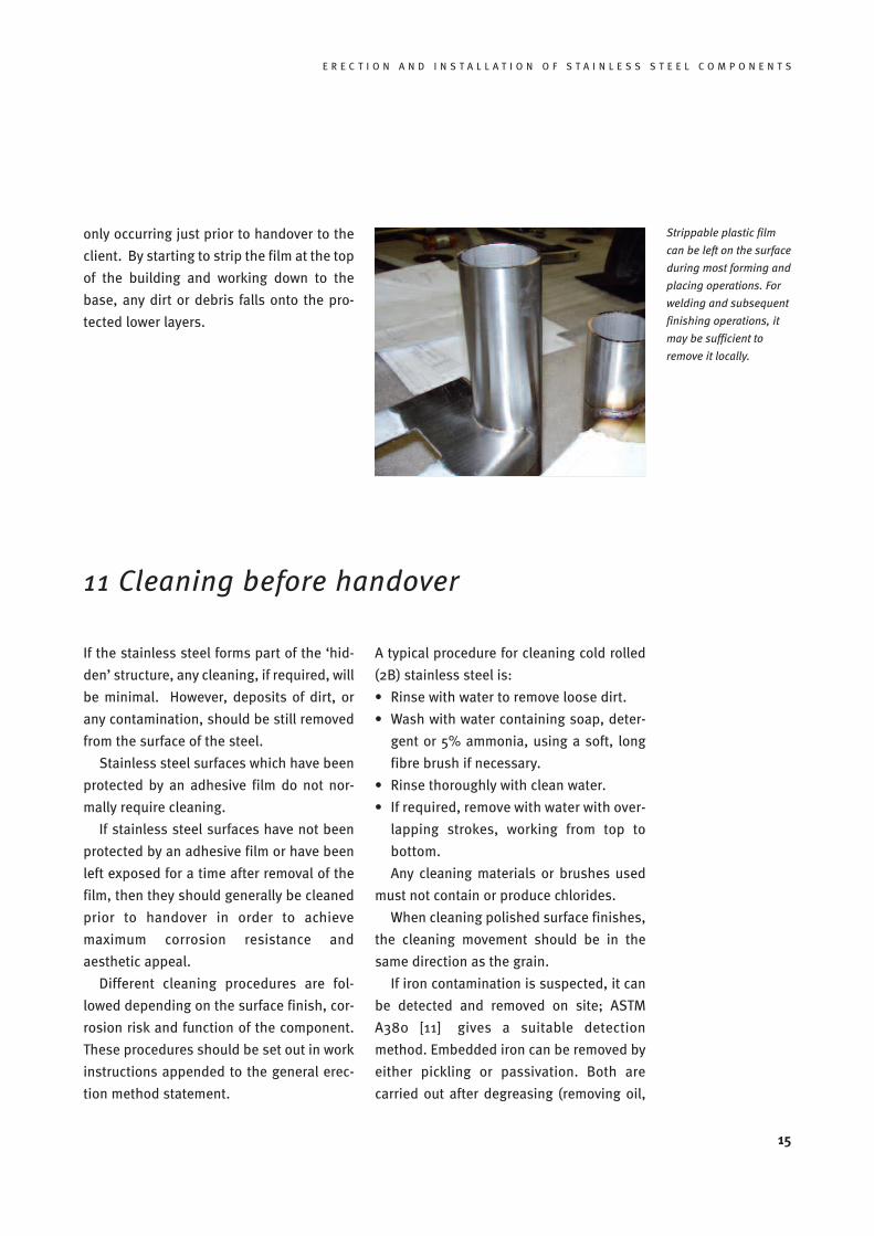
Strippable plastic film
can be left on the surface
during most forming and
placing operations. For
welding and subsequent
finishing operations, it
may be sufficient to
remove it locally.
only occurring just prior to handover to the
client. By starting to strip the film at the top
of the building and working down to the
base, any dirt or debris falls onto the pro-
tected lower layers.
15
If the stainless steel forms part of the ‘hid-
den’ structure, any cleaning, if required, will
be minimal. However, deposits of dirt, or
any contamination, should be still removed
from the surface of the steel.
Stainless steel surfaces which have been
protected by an adhesive film do not nor-
mally require cleaning.
If stainless steel surfaces have not been
protected by an adhesive film or have been
left exposed for a time after removal of the
film, then they should generally be cleaned
prior to handover in order to achieve
maximum corrosion resistance and
aesthetic appeal.
Different cleaning procedures are fol-
lowed depending on the surface finish, cor-
rosion risk and function of the component.
These procedures should be set out in work
instructions appended to the general erec-
tion method statement.
A typical procedure for cleaning cold rolled
(2B) stainless steel is:
• Rinse with water to remove loose dirt.
• Wash with water containing soap, deter-
gent or 5% ammonia, using a soft, long
fibre brush if necessary.
• Rinse thoroughly with clean water.
• If required, remove with water with over-
lapping strokes, working from top to
bottom.
Any cleaning materials or brushes used
must not contain or produce chlorides.
When cleaning polished surface finishes,
the cleaning movement should be in the
same direction as the grain.
If iron contamination is suspected, it can
be detected and removed on site; ASTM
A380 [11] gives a suitable detection
method. Embedded iron can be removed by
either pickling or passivation. Both are
carried out after degreasing (removing oil,
16
E R E C T I O N A N D I N S T A L L A T I O N O F S T A I N L E S S S T E E L C O M P O N E N T S
grease and other organic contamination).
Many of the cleaning techniques used for
bare stainless steel should not be used on
chemically coloured/painted stainless
steel, as the colouring systems are more
delicate than the steel surface. Specific
advice should be sought from suppliers.
Site repair of these finishes is not usually
possible, and therefore the planning of hand-
ling and installation needs to be especially
thorough to prevent damage arising.
The strong acid (chloride-based) solutions
sometimes used to clean the masonry and
tiling of buildings should not be permitted
to come into contact with any metal, includ-
ing stainless steel. If such contamination
does happen, the acid solution must be
washed off immediately with large amounts
of water. If practical, operations should be
sequenced so that any ceramic tile fixing
and cleaning is completed before neigh-
bouring stainless steel components such as
skirting boards or kick plates are installed.
Otherwise, special measures will be needed
to control run-off from wet trades taking
place in areas adjacent to and above loca-
tions where stainless steel components are
installed. Grouting of structural compon-
ents made of stainless steel will bring
alkaline products directly into contact with
them, and the implications of this will need
to be addressed.
Care must be taken to ensure that any
cleaning materials or rinsing agents used
do not adversely affect surrounding mater-
ials e.g. blockwork, other metals, insulation
or caulking compounds [12, 13].
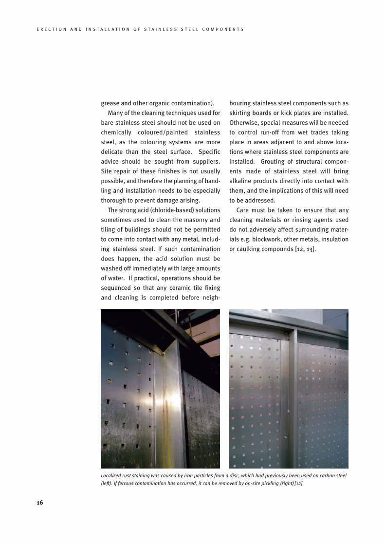
Localized rust staining was caused by iron particles from a disc, which had previously been used on carbon steel
(left). If ferrous contamination has occurred, it can be removed by on-site pickling (right) [12]
E R E C T I O N A N D I N S T A L L A T I O N O F S T A I N L E S S S T E E L C O M P O N E N T S
12 Dissimilar metal contact
If dissimilar metals are in contact with mois-
ture present, then there is a risk of bimetal-
lic corrosion. To avoid this risk, direct con-
tact between stainless steels and other
metals and alloys should be avoided, if pos-
sible. If dissimilar metal contact cannot be
avoided, then it is general good practice to
provide insulation between the materials,
although this is not always necessary in
benign environments, and in some cases is
impractical. As an alternative, it may be
possible to circumvent the risk of corrosion
by preventing the ingress of water that
might otherwise act as the electrolyte.
The method adopted to avoid electrolytic
contact or prevent ingress of water will
depend on the detail in question and
should be agreed with the stainless steel
supplier. However, these methods can be
difficult to install reliably and require care-
ful attention to detail. The figure overleaf
shows an isolation detail at a bolted con-
nection, accompanied by installation notes.
It is essential to use stainless steel fas-
teners for connecting stainless steel com-
ponents (cf. box overleaf).
If stainless steel is to be welded to car-
bon steel, the corrosion protection applied
to the carbon steel component or structure
must continue over the cleaned weld zone
and extend at least 20 mm onto the stain-
less steel, with the layers of a coated appli-
cation suitably lapped over.
17
Bimetallic corrosionIf dissimilar metals are in a common elec-
trolyte, then an electric current may flow
from the less noble metal (the ‘anode’) to
the more noble metal (the ‘cathode’), and
the less noble one will corrode away at a
faster rate than would have occurred if the
metals were not in contact. This is called
bimetallic (galvanic) corrosion. Stainless
steels generally form the cathode in a
bimetallic couple and therefore it is usually
the other metal in the couple which may suf-
fer additional corrosion.
Typical electrolytes encountered in con-
struction are rain or condensation. The rate
of corrosion depends on the relative area of
the metals in contact, the temperature and
the composition of the electrolyte. The gen-
eral behaviour of metals in bimetallic con-
tact in rural, urban, industrial and coastal
environments is documented e.g. in BS PD
6484 Commentary on corrosion at bimetallic
contacts and its alleviation [14].
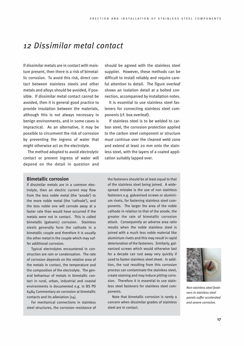
For mechanical connections in stainless
steel structures, the corrosion resistance of
the fasteners should be at least equal to that
of the stainless steel being joined. A wide-
spread mistake is the use of non stainless
fasteners e.g. galvanised screws or alumini-
um rivets, for fastening stainless steel com-
ponents. The larger the area of the noble
cathode in relation to that of the anode, the
greater the rate of bimetallic corrosion
attack. Consequently an adverse area ratio
results when the noble stainless steel is
joined with a much less noble material like
aluminium rivets and this may result in rapid
deterioration of the fasteners. Similarly, gal-
vanized screws which would otherwise last
for a decade can rust away very quickly if
used to fasten stainless steel sheet. In addi-
tion, the rust resulting from this corrosion
process can contaminate the stainless steel,
create staining and may induce pitting corro-
sion. Therefore it is essential to use stain-
less steel fasteners for stainless steel com-
ponents.
Note that bimetallic corrosion is rarely a
concern when dissimilar grades of stainless
steel are in contact.
Non-stainless steel faste-
ners in stainless steel
panels suffer accelerated
and severe corrosion.
18
E R E C T I O N A N D I N S T A L L A T I O N O F S T A I N L E S S S T E E L C O M P O N E N T S
Installation notes:
1. During assembly it is important to install the
insulating materials as detailed and to avoid
damaging them.
2. In general, the bolt assembly will be one of
several in a connection joint. In that case the
connection should be carefully aligned first
using suitable metal drifts or podger span-
ners.
3. If the bolt assembly is used singly, the con-
nection cannot be both aligned and held in
position using a metal drift or podger span-
ner. In that case, some other means needs to
be adopted to hold the connected parts in
alignment whilst the single bolt is inserted.
It is not acceptable to force the connection
into alignment by driving home the bolt itself
as this will damage the insulating bush
around the bolt barrel.
4. Prior to bolt installation, the insulating gas-
kets at each bolt location will need to have
been positioned already. This may require
that the gaskets are secured in their pos-
itions by adhesive that will not damage the
long term integrity of the gasket material.
5. After alignment, the holes in the plates to be
attached should be checked to ensure that
they are sufficiently well aligned not to damage
the insulating bush around the barrel of each
bolt as they are inserted.
6. The detail adopted should ensure that there
is sufficient clearance between the bolt bar-
rel itself and the internal diameter of the
holes to accommodate the thickness of the
insulating bush after allowing for adverse
manufacturing tolerances and some residual
lack of perfect alignment between the holes
in the plates to be connected. This may be
checked in a trial assembly of a typical con-
nection in the works before commencement
on site
7. Immediately after each bolt assembly is com-
pleted it should not be fully tightened until
all bolts in the connection are in position.
Then the bolts should be tightened in a con-
trolled sequence starting from the centre of
the bolt group and moving outwards.
8. Care needs to be taken not to over-tighten
the bolts as this may result in the insulating
gaskets and washers being squeezed and
damaged. Control of the applied torque may
necessitate the use of a calibrated wrench,
or it may be possible to develop a careful
procedure based on practice on a trial
assembly using a suitably-sized spanner.
9. After assembly, or later after a period of use, it
is possible to check the integrity of the insula-
tion using an electrical resistance meter or
megger. However, this only provides reliable
results in truly dry conditions, and if there is no
alternative electrical conduction path through
other connected structural components.
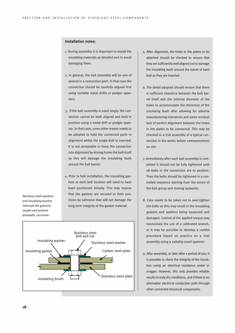
Stainless steel washers
and insulating bushes
interrupt the galvanic
couple and prevent
bimetallic corrosion
Stainless steel plateInsulating brush
Insulating gasket
Insulating washer
Stainless steelbolt and nut
Stainless steel washer
Carbon steel plate
E R E C T I O N A N D I N S T A L L A T I O N O F S T A I N L E S S S T E E L C O M P O N E N T S
19
13 Cladding installation
13.1 Surface consistency
It is particularly important to ensure appro-
priate storage and handling procedures are
followed for components made from thin
gauge material because they are more vul-
nerable to damage.
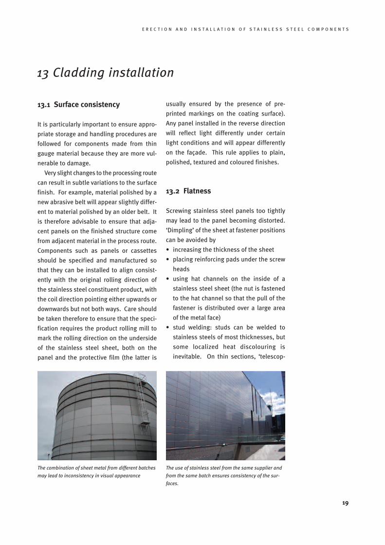
Very slight changes to the processing route
can result in subtle variations to the surface
finish. For example, material polished by a
new abrasive belt will appear slightly differ-
ent to material polished by an older belt. It
is therefore advisable to ensure that adja-
cent panels on the finished structure come
from adjacent material in the process route.
Components such as panels or cassettes
should be specified and manufactured so
that they can be installed to align consist-
ently with the original rolling direction of
the stainless steel constituent product, with
the coil direction pointing either upwards or
downwards but not both ways. Care should
be taken therefore to ensure that the speci-
fication requires the product rolling mill to
mark the rolling direction on the underside
of the stainless steel sheet, both on the
panel and the protective film (the latter is
usually ensured by the presence of pre-
printed markings on the coating surface).
Any panel installed in the reverse direction
will reflect light differently under certain
light conditions and will appear differently
on the façade. This rule applies to plain,
polished, textured and coloured finishes.
13.2 Flatness
Screwing stainless steel panels too tightly
may lead to the panel becoming distorted.
‘Dimpling’ of the sheet at fastener positions
can be avoided by
• increasing the thickness of the sheet
• placing reinforcing pads under the screw
heads
• using hat channels on the inside of a
stainless steel sheet (the nut is fastened
to the hat channel so that the pull of the
fastener is distributed over a large area
of the metal face)
• stud welding: studs can be welded to
stainless steels of most thicknesses, but
some localized heat discolouring is
inevitable. On thin sections, ‘telescop-
The combination of sheet metal from different batches
may lead to inconsistency in visual appearance
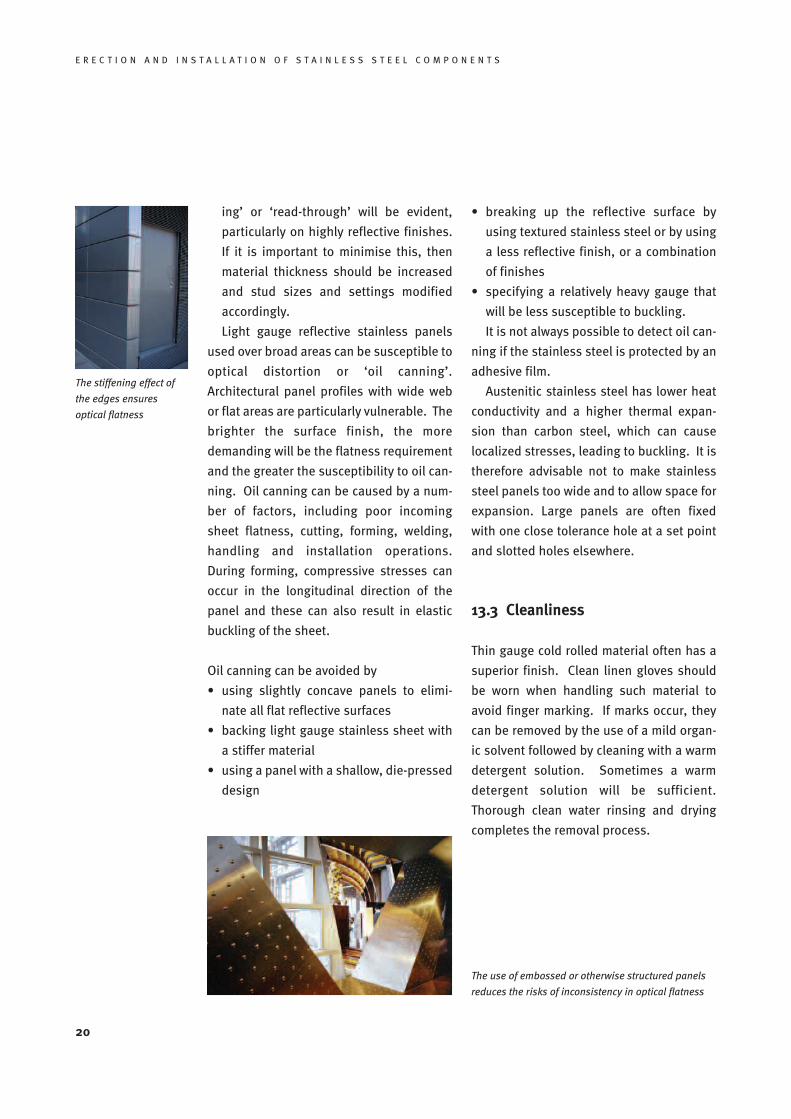
The use of stainless steel from the same supplier and
from the same batch ensures consistency of the sur-
faces.
The stiffening effect of
the edges ensures
optical flatness
ing’ or ‘read-through’ will be evident,
particularly on highly reflective finishes.
If it is important to minimise this, then
material thickness should be increased
and stud sizes and settings modified
accordingly.
Light gauge reflective stainless panels
used over broad areas can be susceptible to
optical distortion or ‘oil canning’.
Architectural panel profiles with wide web
or flat areas are particularly vulnerable. The
brighter the surface finish, the more
demanding will be the flatness requirement
and the greater the susceptibility to oil can-
ning. Oil canning can be caused by a num-
ber of factors, including poor incoming
sheet flatness, cutting, forming, welding,
handling and installation operations.
During forming, compressive stresses can
occur in the longitudinal direction of the
panel and these can also result in elastic
buckling of the sheet.
Oil canning can be avoided by
• using slightly concave panels to elimi-
nate all flat reflective surfaces
• backing light gauge stainless sheet with
a stiffer material
• using a panel with a shallow, die-pressed
design
• breaking up the reflective surface by
using textured stainless steel or by using
a less reflective finish, or a combination
of finishes
• specifying a relatively heavy gauge that
will be less susceptible to buckling.
It is not always possible to detect oil can-
ning if the stainless steel is protected by an
adhesive film.
Austenitic stainless steel has lower heat
conductivity and a higher thermal expan-
sion than carbon steel, which can cause
localized stresses, leading to buckling. It is
therefore advisable not to make stainless
steel panels too wide and to allow space for
expansion. Large panels are often fixed
with one close tolerance hole at a set point
and slotted holes elsewhere.
13.3 Cleanliness
Thin gauge cold rolled material often has a
superior finish. Clean linen gloves should
be worn when handling such material to
avoid finger marking. If marks occur, they
can be removed by the use of a mild organ-
ic solvent followed by cleaning with a warm
detergent solution. Sometimes a warm
detergent solution will be sufficient.
Thorough clean water rinsing and drying
completes the removal process.
20
E R E C T I O N A N D I N S T A L L A T I O N O F S T A I N L E S S S T E E L C O M P O N E N T S
The use of embossed or otherwise structured panels
reduces the risks of inconsistency in optical flatness
E R E C T I O N A N D I N S T A L L A T I O N O F S T A I N L E S S S T E E L C O M P O N E N T S
21
Checklist:
Successful communicationbetween designer and fabricator
To ensure that the architect or structural
engineer, on the one hand, and the
metal builder or fabricator on the other
hand share a common understanding of
the key issues, a short checklist on the
most common points of discussion has
been drawn up:
• Has the stainless steel grade been
specified clearly using the grade des-
ignations in EN 10088 part 1 [15]?
• Has the finish been described accord-
ing to the definitions in EN 10088
part 2 [16] and have samples been
agreed between the architect and the
supplier?
• Is it ensured that in critical visible
applications material from the same
batch will be used?
• Have precautions been taken that
decorative fabricated components
are aligned consistently with the
rolling direction?
• Does the design avoid recess areas,
where dirt and moisture can accumu-
late?
• Has the fabricator demonstrated his
experience in stainless steel in previ-
ous work?
• Does the fabricator separate carbon
steel and stainless steel fabrication
and does he use separate sets of
hand tools?
• Is it ensured that only stainless steel
fasteners are used in contact with
stainless steel?
• Where bimetallic contact exists (e.g.
stainless steel and carbon steel,
stainless steel and aluminium…), has
the risk of galvanic corrosion been
excluded, e.g. by avoiding any elec-
trically conductive contact between
the partner materials?
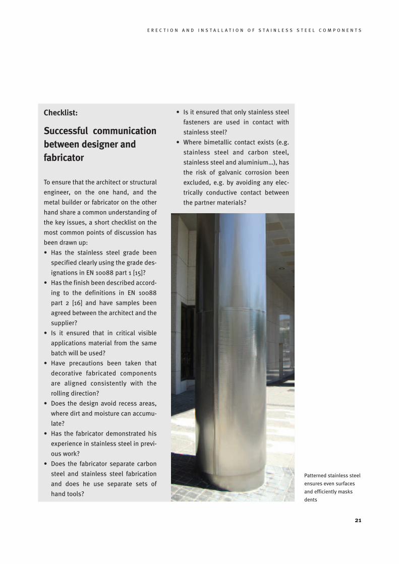
Patterned stainless steel
ensures even surfaces
and efficiently masks
dents
22
E R E C T I O N A N D I N S T A L L A T I O N O F S T A I N L E S S S T E E L C O M P O N E N T S
14 Fasteners
The proper installation of stainless steel
fasteners is critical to the performance of
the installed component. This is particular-
ly important with respect to tightening and
galling. Galling occurs when the stainless
steel oxide surface film breaks down as a
result of direct metal contact. Solid-phase
welding can then take place (when material
is transferred from one surface to another).
Galling results in surface damage, and seiz-
ing and freezing up of equipment. This may
occur when using stainless steel nuts and
bolts together, when their contact points
are subjected to high tightening torques.
Reasonable care should be exercised in
the handling of fasteners to keep threads
clean and free of dirt, especially coarse
grime, grit or sand, and also to avoid dam-
aging the threads. If threads are tightened
down with sand or grit between them, the
likelihood of galling or seizing in the fasten-
er assembly increases significantly.
Ways to reduce galling include:
Use rolled threads
Rolled threads are less susceptible to
galling than machined threads as they have
a smoother surface and the grain lines fol-
low the thread rather than cut across it, as
is the case with machined threads.
Tighten to the correct torque
Overtightening increases the likelihood of
galling; bolts should be tightened to the
correct torque using a torque wrench.
Lubrication
Some forms of lubrication applied to
threads prior to assembly can reduce the
likelihood of galling. Proprietary grease-
type lubricants, containing tenacious met-
als, oils etc are available. However, greas-
ing bolts may result in contamination by dirt
and can present problems for storage.
Stainless steel screws are available with an
additional zinc coating, which also has a
lubricating effect.
Hardness modification
Galling can also be reduced by using dis-
similar standard grades of stainless steel
which vary in composition, work hardening
rate and hardness (e.g. grade A2-C4, A4-C4
or A2-A4 bolt-nut combination from EN ISO
3506-1 and -2 [17]. In severe cases, a propri-
etary high work-hardening stainless steel
alloy may be used for one component or
hard surface coatings applied, e.g. nitriding
or hard chromium plating. Note that if dis-
similar metals or coatings are used, it is
necessary to ensure that the required corro-
sion resistance is obtained.
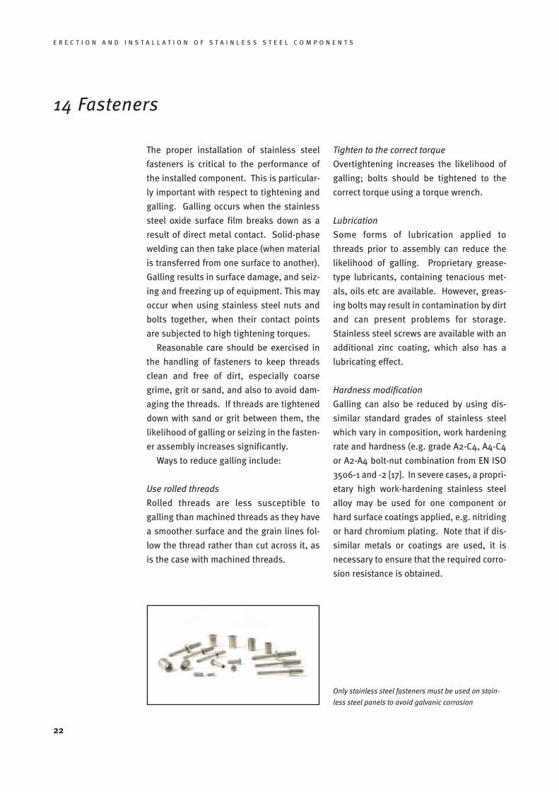
Only stainless steel fasteners must be used on stain-
less steel panels to avoid galvanic corrosion
E R E C T I O N A N D I N S T A L L A T I O N O F S T A I N L E S S S T E E L C O M P O N E N T S
23
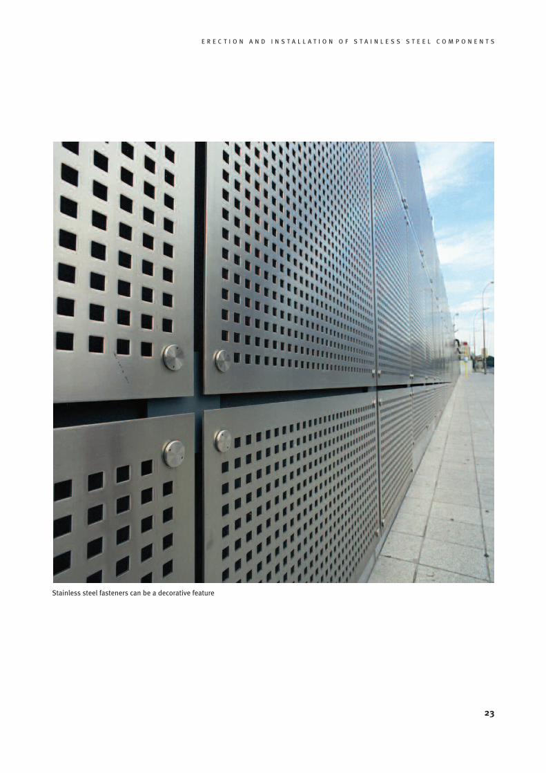
Stainless steel fasteners can be a decorative feature
24
E R E C T I O N A N D I N S T A L L A T I O N O F S T A I N L E S S S T E E L C O M P O N E N T S
15 References
[1] CUNAT, Pierre-Jean, “Stainless Steel as a Lightweight Material for the Building
Envelope”, Proceedings of the conference Stainless Steel in Structures, Brussels: Euro
Inox, 2000; also available online at www.euro-inox.org
[2] Design Manual for Structural Stainless Steel, Third Edition (Building Series, Vol. 11),
Luxembourg / London: Euro Inox and The Steel Construction Institute, 2006
[3] prEN 1090 – 1 Steel and aluminium structural components. General delivery conditi-
ons, September 2004.
[4] prEN 1090 – 2 Execution of steel structures and aluminium structures. Technical requi-
rements for the execution of steel structures, April 2005.
[5] ENV 1090 – 6, Execution of steel structures. Supplementary rules for stainless steel,
January 2000
[6] prEN 1991, Actions on Structures, Part 1-6: General Actions. Actions during execution
[7] Tables of Technical Properties (Materials and Applications Series, Volume 5),
Luxembourg: Euro Inox 2004; also available as a searchable online data base at
www.euro-inox.org
[8] A visual demonstration of good practice is shown in the video Stainless Steel against
Corrosion, available from Euro Inox on CD-ROM and DVD
[9] EN 1011-3, Welding. Recommendations for welding of metallic materials. Arc welding
of stainless steels, CEN, 2000
[10] CUNAT, Pierre-Jean, Welding Stainless Steel (Materials and Applications Series,
Volume 3), Luxembourg: Euro Inox 2000
[11] ASTM A 380, Practice for cleaning and descaling stainless steel parts, equipment and
systems, ASTM, 1994
[12] CROOKES, Roger, Pickling and Passivating Stainless Steel (Materials and Applications
Series, Volume 4), Luxembourg: Euro Inox 2004
[13] The Cleaning and Maintenance of Stainless Architectural Finishes, Luxembourg: Euro
Inox 2002
[14] BS PD 6484, Commentary on corrosion at bimetallic contacts and its alleviation,
British Standards Institute, 1980
[15] BS EN 10088-1, Stainless steels. List of stainless steels, CEN 2005
[16] BS EN 10088-2, Stainless steels. Technical delivery conditions for sheet/plate and
strip of corrosions resisting steel for general purposes, CEN 2005
[17] EN ISO 3506, Mechanical properties of corrosion-resistant stainless-steel fasteners.
Part 1: Bolts, screws and studs, Part 2: Nuts, CEN, 1998

Diamant Building • Bd. A. Reyers 80 • 1030 Brussels • Belgium • Phone +32 2 706 82-67 • Fax -69 • e-mail [email protected] • www.euro-inox.org
ISBN 2-87997-143-8