erection sequence - steel...
TRANSCRIPT

ERECTION SEQUENCE
OUTSIDE CLOSURE
After all panel runs are installed and seamed, return to first panel run at the ridge. Remove temporary fasteners from panel and install Tri-Bead tape sealer across full width of panel, covering the prepunched holes.
Rotate outside closure into position contact-
ing the female side of the panel first. Using an awl, align the first hole on the female side of the outside closure with the corresponding hole in the panel and back-up plate. Remove the awl and install Fastener #1E in this hole.
Push the other end of the outside closure
into position and align the holes with the awl. Remove the awl and install Fastener #1E in all remaining holes except for the hole at the panel seam. Do not install the panel seam fastener at this time.
Install all outside closures on both sides of the ridge.
If the last panel run was field modified, the
final outside closure on the last panel will require field modification as well. A tab should be formed on the end of the outside closure for attachment to the upturned leg of the roof panel (field formed). This tab should be attached to the panel with Fastener #1E, two required.
Install Fastener #1E in remaining hole at the
panel seam of all outside closures. The fas- tener installed in the top hole must go through the panel seam and the corresponding hole of the adjacent outside closure.
Use urethane sealant to fill any voids around
panel seam on upslope side of outside clo- sure.
42 SUBJECT TO CHANGE WITHOUT NOTICE

ERECTION SEQUENCE
RIDGE-OUTSIDE
CLOSURE/FLASHING
Apply Tri-Bead tape sealer to the top of the outside closure.
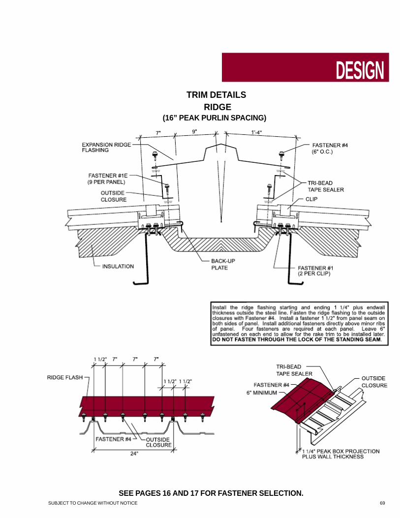
Install the ridge flashing starting and ending 11/4” plus wall thickness outside the steel line. Fasten the ridge flashing to the outside clo- sures with Fastener #4. Install a fastener 11/2” from panel seam on both sides of panel. Install additional fasteners directly above minor ribs of panel. Four fasteners are required at each panel. Leave 6” unfastened on each end to allow for the rake trim to be installed later. DO NOT FASTEN THROUGH THE LOCK OF THE STANDING SEAM.
For floating peak box installation see page 72 or 74.
SUBJECT TO CHANGE WITHOUT NOTICE 43
SPECIAL ERECTION TECHNIQUES
RECOMMENDED
ERECTION PRACTICES
CORRECTING OUT-OF-PLANE
SUBSTRUCTURE
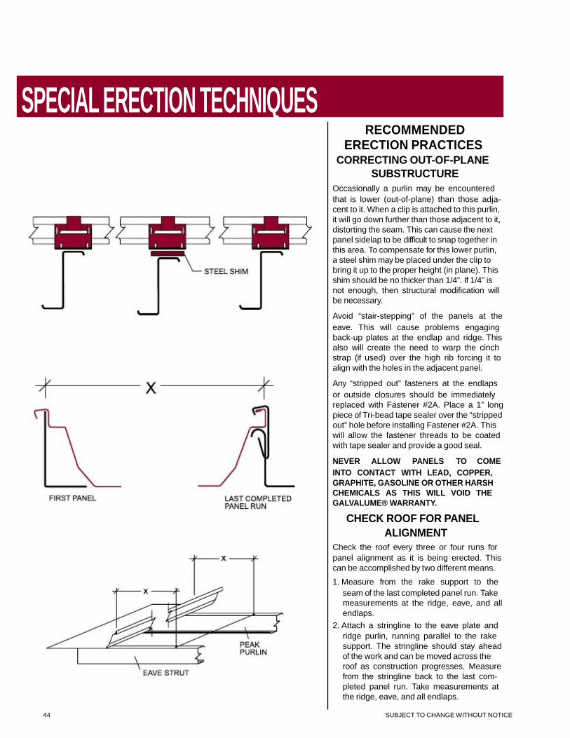
Occasionally a purlin may be encountered that is lower (out-of-plane) than those adja- cent to it. When a clip is attached to this purlin, it will go down further than those adjacent to it, distorting the seam. This can cause the next panel sidelap to be difficult to snap together in this area. To compensate for this lower purlin, a steel shim may be placed under the clip to bring it up to the proper height (in plane). This shim should be no thicker than 1/4”. If 1/4” is not enough, then structural modification will be necessary.
Avoid “stair-stepping” of the panels at the eave. This will cause problems engaging back-up plates at the endlap and ridge. This also will create the need to warp the cinch strap (if used) over the high rib forcing it to align with the holes in the adjacent panel.
Any “stripped out” fasteners at the endlaps or outside closures should be immediately replaced with Fastener #2A. Place a 1” long piece of Tri-bead tape sealer over the “stripped out” hole before installing Fastener #2A. This will allow the fastener threads to be coated with tape sealer and provide a good seal.
NEVER ALLOW PANELS TO COME INTO CONTACT WITH LEAD, COPPER, GRAPHITE, GASOLINE OR OTHER HARSH CHEMICALS AS THIS WILL VOID THE GALVALUME® WARRANTY.
CHECK ROOF FOR PANEL ALIGNMENT
Check the roof every three or four runs for panel alignment as it is being erected. This can be accomplished by two different means.
1. Measure from the rake support to the seam of the last completed panel run. Take measurements at the ridge, eave, and all endlaps.
2. Attach a stringline to the eave plate and ridge purlin, running parallel to the rake support. The stringline should stay ahead of the work and can be moved across the roof as construction progresses. Measure from the stringline back to the last com- pleted panel run. Take measurements at the ridge, eave, and all endlaps.
44 SUBJECT TO CHANGE WITHOUT NOTICE

SPECIAL ERECTION TECHNIQUES
RECOMMENDED
ERECTION PRACTICES
(CONTINUED) ADJUSTING PANEL WIDTH
NOTE
Do not adjust panel width more than 1/2” on any panel area.
ARTICULATING OR
SLIDING CLIP
To stretch panel coverage, install an articulat- ing clip at the panel endlap or ridge with the base angled away from the panel. As the fastener is installed through the base of the clip and into the purlin, the clip base will rotate down to the purlin causing the top of the clip to move outward, stretching the panel coverage. Install the remainder of the clips as usual.
To shrink panel coverage, install an articulat- ing clip at the panel endlap or ridge with the base angled toward the panel. As the fastener is installed through the base of the clip and into the purlin, the clip base will rotate down to the purlin causing the top of the clip to move inward, shrinking panel coverage. Install the remainder of the clips as usual.
FLOATING CLIP
To stretch panel coverage, bend the sides of the back-up plate out and install at endlap or ridge. Do not bend either side more than 1/4”. Install clips as usual.
To shrink panel coverage, bend the sides of the back-up plate in and install at endlap or ridge. Do not bend either side more than 1/4”. Install clips as usual.
SUBJECT TO CHANGE WITHOUT NOTICE 45

SPECIAL ERECTION TECHNIQUES
LIGHT TRANSMITTING
PANEL TRIM
INSTALLATION
(OPTIONAL) Light transmitting panel trim is available to cover the exposed insulation at the sides of the light transmitting panel opening. Two pieces of 2 1/4”x3 1/2”x10’-3” angle are required per light transmitting panel. This angle is designed to work with either the low or the high system. THE 2 1/4” LEG IS TURNED UP FOR THE LOW SYSTEM AND THE 3 1/4” LEG IS TURNED UP FOR THE HIGH SYSTEM.
INSTALLATION PROCEDURE Install panels up to light transmitting panel run. Do not install clips on this run until first light transmitting panel trim piece is installed. Cut and remove insulation where light transmitting panel is to be located. Leave enough insulation at the top and bottom of the opening to be rolled back, allowing only the backing to be exposed. Place double faced tape on top of the horizontal leg of the trim to hold the insulation. Notch trim for back-up plates and install directly under male leg of last panel installed, running from lower light transmitting panel purlin to upper light transmit- ting panel purlin. Attach to purlins with Fastener #1. Install clips. Install lower light transmitting panel run panel. Leave upper-most clip off until next trim piece is installed. Fold insulation end tab under lower panel and install light transmit- ting panel. Fold upper insulation end tab above light transmitting panel. Fold upper insulation end tab above light transmitting panel and install upper light transmitting panel. Place double faced tape on next trim piece and notch for back- up plates. Install directly under male leg of light transmitting panel and clip all panels down.
CAUTION The following are examples of conditions that may cause condensation on light transmitting panels: (A) Projects where outside winter temperatures below 40°F are anticipated and where average winter interior relative humidity of 45% or greater is expected. (B) Building usages with high humidity interiors, such as indoor swimming pools, textile manufactur- ing operations, food paper or other wet- process industrial plants. (C) Construction elements that may release moisture after the roof is installed, such as interior concrete and masonry, plaster finishes and fuel burning heaters. Manufacturer is not responsible for determining if condensation will be an issue on any particular application.
46 SUBJECT TO CHANGE WITHOUT NOTICE

SPECIAL ERECTION TECHNIQUES
RIDGE VENTILATOR
INSTALLATION
NOTE
The manufacturer does not recommend the use of a ridge ventilator on standing seam roof systems. Sidewall or endwall exhaust fans or other ventilating methods should be considered. These details are for your convenience only. Do not use ridge ven- tilators on any roof over 200’ in width or with a slope less than 1:12 or greater than 6:12.
Turn ventilator over and place gently on its top. Note that the end cap is pre-formed for a 1:12 roof pitch. The five bench mark dots represent 2:12, 3:12, 4:12, 5:12 and 6:12 roof pitches. Draw a line between indicated corners and the appropriate dot for the roof pitch. Cut and remove that portion of the end cap. On 5:12 and 6:12 roof pitches see vent manufacturer’s special instructions for the installation of the vent skirt. The end cap is now ready to receive the end skirt.
Position end skirt onto end cap. Be sure the down-turned angle of the end skirt is inside of and up against the end cap. Attach end skirt to ventilator end cap with Fastener #4 in four places.
SUBJECT TO CHANGE WITHOUT NOTICE 47
SPECIAL ERECTION TECHNIQUES
RIDGE VENTILATOR
INSTALLATION
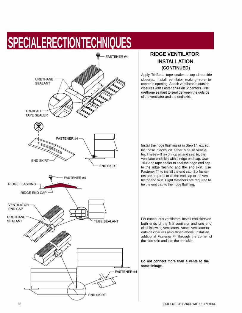
(CONTINUED) Apply Tri-Bead tape sealer to top of outside closures. Install ventilator making sure to center in opening. Attach ventilator to outside closures with Fastener #4 on 6” centers. Use urethane sealant to seal between the outside of the ventilator and the end skirt.
Install the ridge flashing as in Step 14, except for those pieces on either side of ventila- tor. These will lay on top of, and seal to, the ventilator end skirt with a ridge end cap. Use Tri-Bead tape sealer to seal the ridge end cap to the ridge flashing and the end skirt. Use Fastener #4 to install the end cap. Six fasten- ers are required to tie the end cap to the ven- tilator end skirt. Eight fasteners are required to tie the end cap to the ridge flashing.
For continuous ventilators, install end skirts on both ends of the first ventilator and one end of all following ventilators. Attach ventilator to outside closures as outlined above. Install an additional Fastener #4 through the corner of the side skirt and into the end skirt.
Do not connect more than 4 vents to the same linkage.
48 SUBJECT TO CHANGE WITHOUT NOTICE

SPECIAL ERECTION TECHNIQUES
12” X 10’-0” RIDGE VENTILATORS
SUBJECT TO CHANGE WITHOUT NOTICE 49

SPECIAL ERECTION TECHNIQUES
OUTSIDE CLOSURE LOCATION AT 12” x 10’-0” RIDGE VENT
50 SUBJECT TO CHANGE WITHOUT NOTICE

SPECIAL ERECTION TECHNIQUES
RIDGE VENTILATORS (12” X 10’-0”)
SUBJECT TO CHANGE WITHOUT NOTICE 51
SPECIAL ERECTION TECHNIQUES
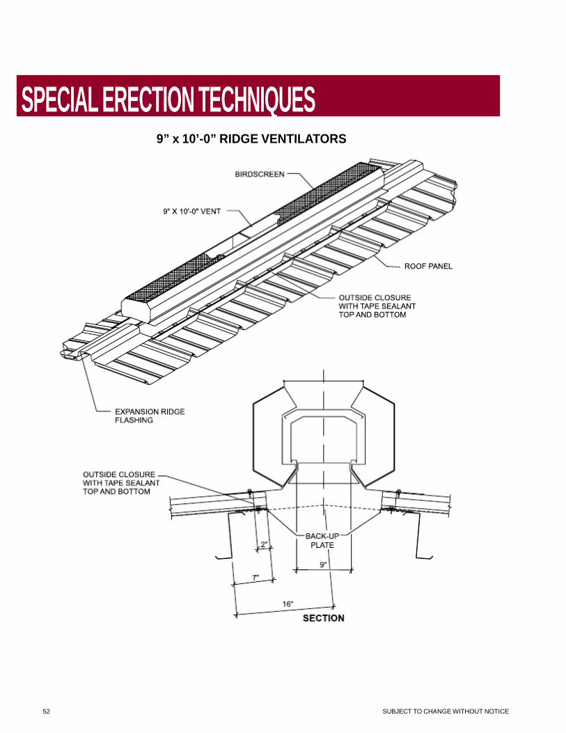
9” x 10’-0” RIDGE VENTILATORS
52 SUBJECT TO CHANGE WITHOUT NOTICE
SPECIAL ERECTION TECHNIQUES
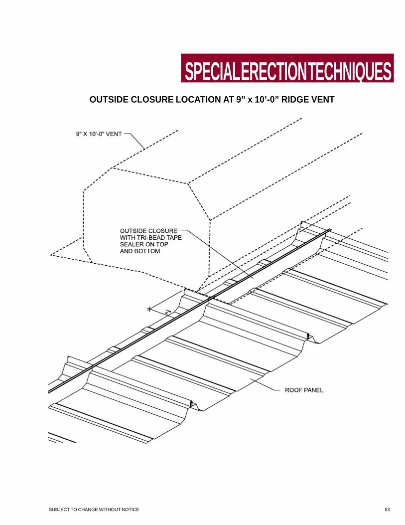
OUTSIDE CLOSURE LOCATION AT 9” x 10’-0” RIDGE VENT
SUBJECT TO CHANGE WITHOUT NOTICE 53

SPECIAL ERECTION TECHNIQUES
RIDGE VENTILATORS (9” x 10’-0”)
54 SUBJECT TO CHANGE WITHOUT NOTICE
SPECIAL ERECTION TECHNIQUES
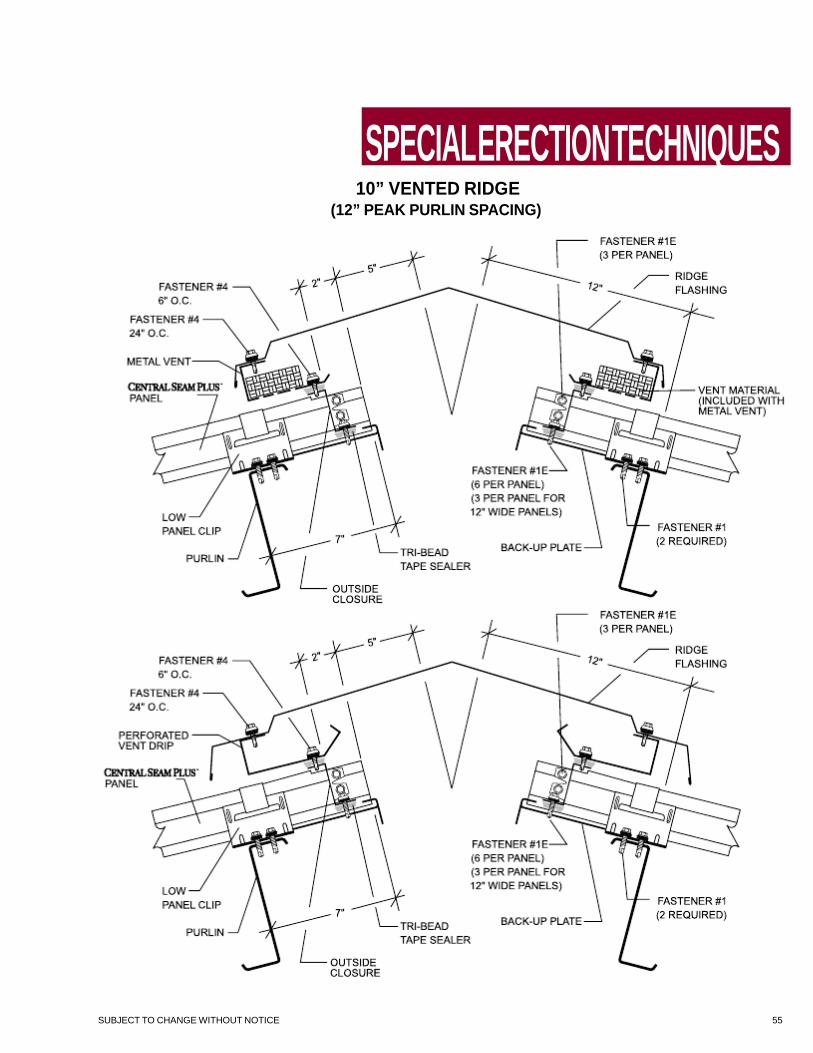
10” VENTED RIDGE
(12” PEAK PURLIN SPACING)
SUBJECT TO CHANGE WITHOUT NOTICE 55

SPECIAL ERECTION TECHNIQUES
18” VENTED RIDGE
(16” PEAK PURLIN SPACING)
56 SUBJECT TO CHANGE WITHOUT NOTICE

SPECIAL ERECTION TECHNIQUES
MID-SLOPE FIXED
CONDITION
**Profile May Vary
NOTES: 1. This special detail is for use when a panel run exceeds the thermal movement capabilities of the panel clip. Floating
clips have a maximum movement of 1” in each direction. Articulating clips have a maximum movement of 1 1/4” in each direction. Thermal calculations must be performed for each project to ensure that the thermal movement of the roof will not exceed the design of the clips and slot in the floating eave plate.
2. A positive panel attachment is made at the mid-point in the panel run allowing for thermal movement to the eave and ridge.
3. The standard floating ridge condition must be used in conjunction with this special eave detail. 4. The floating eave plate must be used to allow for panel movement at the eave.
SUBJECT TO CHANGE WITHOUT NOTICE 57

SPECIAL ERECTION TECHNIQUES
ROOF CURB
INSTALLATION
The manufacturer recommends that only one- piece aluminum curbs be used on it’s stand- ing seam roof systems. The curb flange is constructed to match the configuration of the panel. The side flange extends to the next nat- ural seam in the roof panel and conforms to the seam configuration. Cap strips, furnished by the curb manufacturer, secure the curb to the roof panels. The roof curb is installed under the roof panels on the upslope end and on top of the roof panels on the downslope end. Support framing should be installed before curb installation. Back-up plates (for the roof panels at the down slope end of the curb), a floating eave plate (for the upslope end of the curb), long-life fasten- ers and Triple Bead tape sealer must be ordered for each curb.
These curbs may be installed as the roof is being installed or after the roof has been installed. Since the curb sides are an integral part of the roof seam, the curb must align with the roof panel seams. If the curb can be shifted up to 12” to either side, the curb can be pre-ordered and be installed with the roof panels or installed after the roof is in place. If the curb placement is critical, install the curb support framing at the desired location and roof over it. Measure the panel rib locations in reference to the required curb opening and order the roof curb for each location. The curbs can then be installed in each location, ensuring an exact fit.
ATTENTION All curbs must be installed over support framing, supplied by the metal build- ing manufacturer or the curb supplier. Support framing must be properly locat- ed to provide “endlap” conditions at the upslope and downslope ends of the curb. Refer to Roof Curb Cross Section for critical dimensions.
58 SUBJECT TO CHANGE WITHOUT NOTICE
SPECIAL ERECTION TECHNIQUES
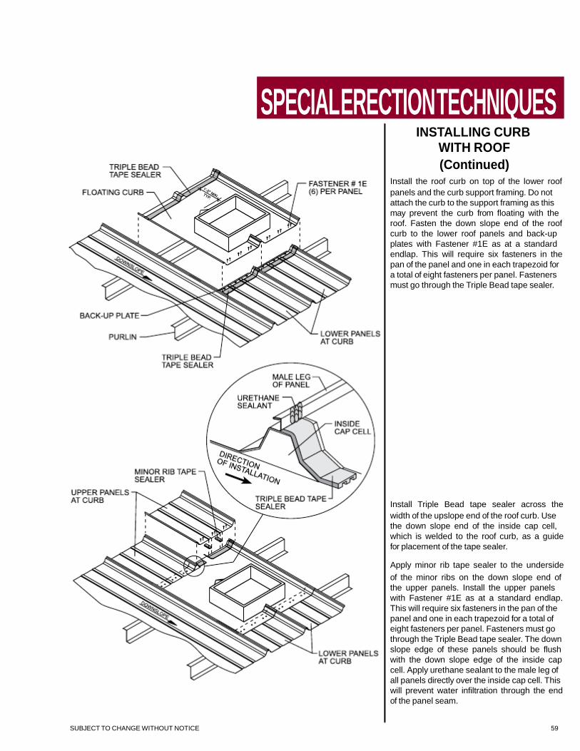
INSTALLING CURB
WITH ROOF
(Continued) Install the roof curb on top of the lower roof panels and the curb support framing. Do not attach the curb to the support framing as this may prevent the curb from floating with the roof. Fasten the down slope end of the roof curb to the lower roof panels and back-up plates with Fastener #1E as at a standard endlap. This will require six fasteners in the pan of the panel and one in each trapezoid for a total of eight fasteners per panel. Fasteners must go through the Triple Bead tape sealer.
Install Triple Bead tape sealer across the width of the upslope end of the roof curb. Use the down slope end of the inside cap cell, which is welded to the roof curb, as a guide for placement of the tape sealer.
Apply minor rib tape sealer to the underside of the minor ribs on the down slope end of the upper panels. Install the upper panels with Fastener #1E as at a standard endlap. This will require six fasteners in the pan of the panel and one in each trapezoid for a total of eight fasteners per panel. Fasteners must go through the Triple Bead tape sealer. The down slope edge of these panels should be flush with the down slope edge of the inside cap cell. Apply urethane sealant to the male leg of all panels directly over the inside cap cell. This will prevent water infiltration through the end of the panel seam.
SUBJECT TO CHANGE WITHOUT NOTICE 59

SPECIAL ERECTION TECHNIQUES
INSTALLING CURB
WITH ROOF
Install curb support framing at curb location. Install full length roof panels up to curb loca- tion. Install lower panels at downslope end of curb. If the lower panels are field cut to length, you must (1) cut the downslope end, leaving a factory cut at the curb end or (2) if the curb end of the panel is field cut, notch the male leg as it is done in the factory. Place Triple Bead tape sealer across the full width of each panel as it is installed. To determine how far down on the panel to place the tape sealer, temporarily lay the curb in place and mark the down slope edge of the curb on the first panel. This will give you a reference point as to how far down slope to place the tape sealer. It is critical that the tape sealer be installed across each panel individually so that the tape sealer can be placed over the male leg. This will provide a seal in the panel seam when the next panel is installed. Install back-up plates onto each of the lower panels.
60 SUBJECT TO CHANGE WITHOUT NOTICE

SPECIAL ERECTION TECHNIQUES
INSTALLING CURB
WITH ROOF
(Continued) Install the roof curb on top of the lower roof panels and the curb support framing. Do not attach the curb to the support framing as this may prevent the curb from floating with the roof. Fasten the down slope end of the roof curb to the lower roof panels and back-up plates with Fastener #1E as at a standard endlap. This will require six fasteners in the pan of the panel and one in each trapezoid for a total of eight fasteners per panel. Fasteners must go through the Triple Bead tape sealer.
Install Triple Bead tape sealer across the width of the upslope end of the roof curb. Use the down slope end of the inside cap cell, which is welded to the roof curb, as a guide for placement of the tape sealer.
Apply minor rib tape sealer to the underside of the minor ribs on the down slope end of the upper panels. Install the upper panels with Fastener #1E as at a standard endlap. This will require six fasteners in the pan of the panel and one in each trapezoid for a total of eight fasteners per panel. Fasteners must go through the Triple Bead tape sealer. The down slope edge of these panels should be flush with the down slope edge of the inside cap cell. Apply urethane sealant to the male leg of all panels directly over the inside cap cell. This will prevent water infiltration through the end of the panel seam.
SUBJECT TO CHANGE WITHOUT NOTICE 61
SPECIAL ERECTION TECHNIQUES
INSTALLING CURB
WITH ROOF
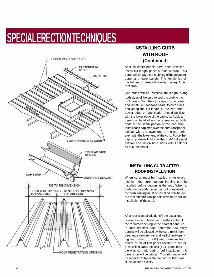
(Continued) After all upper panels have been installed, install full length panel at side of curb. This panel will engage the male leg of the adjacent upper and lower panels. The female leg of this full length panel will overlap the leg of the roof curb.
Cap strips will be installed, full length, along both sides of the curb to seal the curb to the roof panels. Turn the cap strips upside down and install Tri Bead tape sealer to both sides and along the full length of the cap strip. Lower edge of tape sealer should be flush with the lower edge of the cap strip. Apply a generous bead of urethane sealant at both ends of the seam portion of the cap strip. Install each cap strip over the curb/roof panel sidelap with the lower end of the cap strip even with the lower end of the curb. Force the cap strip down tightly to the curb/roof panel sidelap and fasten both sides with Fastener #4 at 6” on center.
INSTALLING CURB AFTER
ROOF INSTALLATION
When curbs must be installed in an exact location, the curb support framing can be installed before beginning the roof. When a curb is to be added after the roof is installed, the curb framing must be installed from below the roof after the roof panels have been cut for installation of the curb.
After roof is installed, identify the exact loca- tion for the curb. Measure from the center of the required opening to the nearest panel rib in each direction. Also, determine how many panels will be affected by the curb (minimum clearance between vertical wall of curb open- ing and panel rib is 6”) and measure from center of rib of first panel affected to center of rib of last panel affected (if 24” panel mod- ule was not held during roof installation, this dimension will be critical). This information will be required to fabricate the curb so that it will fit the location exactly.
62 SUBJECT TO CHANGE WITHOUT NOTICE

SPECIAL ERECTION TECHNIQUES
INSTALLING CURB
AFTER ROOF
(Continued) Cap strips will be installed, full length along both sides of the curb to seal the curb to the roof panels. Turn the cap strips upside down and install Tri Bead tape sealer to both sides and along the full length of the cap strip. Lower edge of tape sealer should be flush with the lower edge of the cap strip. Apply a generous bead of urethane sealant at both ends of the seam portion of the cap strip. Install each cap strip over the curb/roof panel sidelap with the lower end of the cap strip even with the lower end of the curb. Force the cap strip down tightly to the curb/roof panel sidelap and fasten both sides with Fastener #4 at 6” on center.
SUBJECT TO CHANGE WITHOUT NOTICE 63

SPECIAL ERECTION TECHNIQUES
INSTALLING CURB
AFTER ROOF
(Continued) Once curb is ready to be installed, lay curb on roof and align opening in the curb with the exact location the opening is required in the roof. At the up slope end of the roof curb, the roof panels will be cut on a line even with the beginning of the notch at the vertical leg on each side of the roof curb. Secondly, trace a line along the down slope edge of the roof curb. The roof panels will be cut on a line 4” up slope from this line.
Cut roof panels from rib of first panel affected by curb, to rib of last panel affected, along the top and bottom cut lines previously marked.
At the down slope end of the roof opening, install back-up plates onto the ends of the cut roof panels and Triple Bead tape sealer across the full width of these roof panels. The down slope edge of the tape sealer should be on the line previously traced along the downslope edge of the roof curb. The up slope edge of the tape sealer will be approximately 1 1/2” from the end of the cut panel.
Apply Triple Bead tape sealer across the full width of the up slope end of the roof curb. The down slope edge of the tape sealer will align with the down slope edge of the inside cap cells welded to the roof curb.
Install the roof curb under the roof panels at the up slope end and on top of the panels at the down slope end. This will require that you lift the roof panels up slightly at the up slope end to allow the upper flange of the roof curb to slide under the panels. Spray some soapy water on the tape sealer to prevent it from sticking to the roof panels until you have the curb completely in place.
64 SUBJECT TO CHANGE WITHOUT NOTICE

SPECIAL ERECTION TECHNIQUES
ROOF CURB
CROSS SECTION
1. Panel
2. Urethane Sealant
3. Outside Cap Cell
4. Back-up Plate
5. Fastener #1E
6. Triple Bead Tape Sealer
7. Roof Curb
8. Water Diverter
9. Inside Cap Cell
10. Floating Eave Plate
11. Fastener #5
12. Purlin Framing Member or Secondary Curb Support Framing
SUBJECT TO CHANGE WITHOUT NOTICE 65

SPECIAL ERECTION TECHNIQUES
GUIDELINES FOR
INSTALLING REPAIR CAP
ON DAMAGED
Central Seam Plus SEAMS
Repair cap must be fabricated from the same gauge material and have the same finish as roof panels and must extend a minimum of 12” above and below the damaged area.
Install a continuous run of Tri-Bead tape sealer to the inside of both legs of the repair cap. Place lower edge of tape sealer approxi- mately 1/4” up from bottom of legs. Fill seam portion of repair cap with urethane sealant. At each end of repair cap, apply a 3/8” bead of sealant across the inside cross section of the repair cap.
Push repair cap down onto panel and fasten with Fastener #4 - 4” O.C. Fasteners must go through tape sealer.
Check repair cap at each end to verify that urethane sealant has sealed across the entire cross section of the repair cap. Wipe off excess sealant.
66 SUBJECT TO CHANGE WITHOUT NOTICE

TRIM DETAILS
EAVE TO ENDLAP
DESIGN
**Profile May Vary
NOTE: THE ABOVE GUTTER IS NOT DESIGNED TO RESIST THE IMPACT LOADS OF SLIDING ICE OR SNOW. IF ICE OR SNOW IS ANTICIPATED THEN USE THE SNOW GUTTER SHOWN ON PAGE 80, 81 AND 82, OR IF THE ABOVE GUTTER IS TO BE USED, IT MUST BE PROTECTED BY THE INSTALLATION OF A SNOW RETENTION DEVICE SUCH AS: S-5™ SnoFence™, SnoRail™, OR S-5™ ColorGard™.
SEE PAGES 16 AND 17 FOR FASTENER SELECTION. SUBJECT TO CHANGE WITHOUT NOTICE 67

DESIGN
TRIM DETAILS
RIDGE
(12” PEAK PURLIN SPACING)
SEE PAGES 16 AND 17 FOR FASTENER SELECTION.
68 SUBJECT TO CHANGE WITHOUT NOTICE
DESIGN
TRIM DETAILS
RIDGE
(16” PEAK PURLIN SPACING)
SEE PAGES 16 AND 17 FOR FASTENER SELECTION. SUBJECT TO CHANGE WITHOUT NOTICE 69

DESIGN
TRIM DETAILS
EXPANSION RIDGE FLASHING LAP
70 SUBJECT TO CHANGE WITHOUT NOTICE
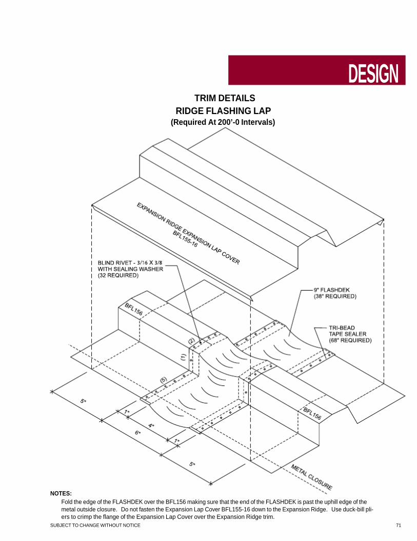
TRIM DETAILS
RIDGE FLASHING LAP
(Required At 200’-0 Intervals)
DESIGN
NOTES: Fold the edge of the FLASHDEK over the BFL156 making sure that the end of the FLASHDEK is past the uphill edge of the metal outside closure. Do not fasten the Expansion Lap Cover BFL155-16 down to the Expansion Ridge. Use duck-bill pli- ers to crimp the flange of the Expansion Lap Cover over the Expansion Ridge trim.
SUBJECT TO CHANGE WITHOUT NOTICE 71

DESIGN
TRIM DETAILS
STANDARD GUTTER EXPANSION LAP DETAIL
PROFILE MAY VARY
(Required At 200’-0 Intervals)
NOTES:
1. Install Gutter End Caps with Tube Sealant as shown. 2. Notch Gutter Lips as shown. 3. Insert Right Gutter into Left Gutter. Do Not Attach the Left and Right Gutters together.
72 SUBJECT TO CHANGE WITHOUT NOTICE
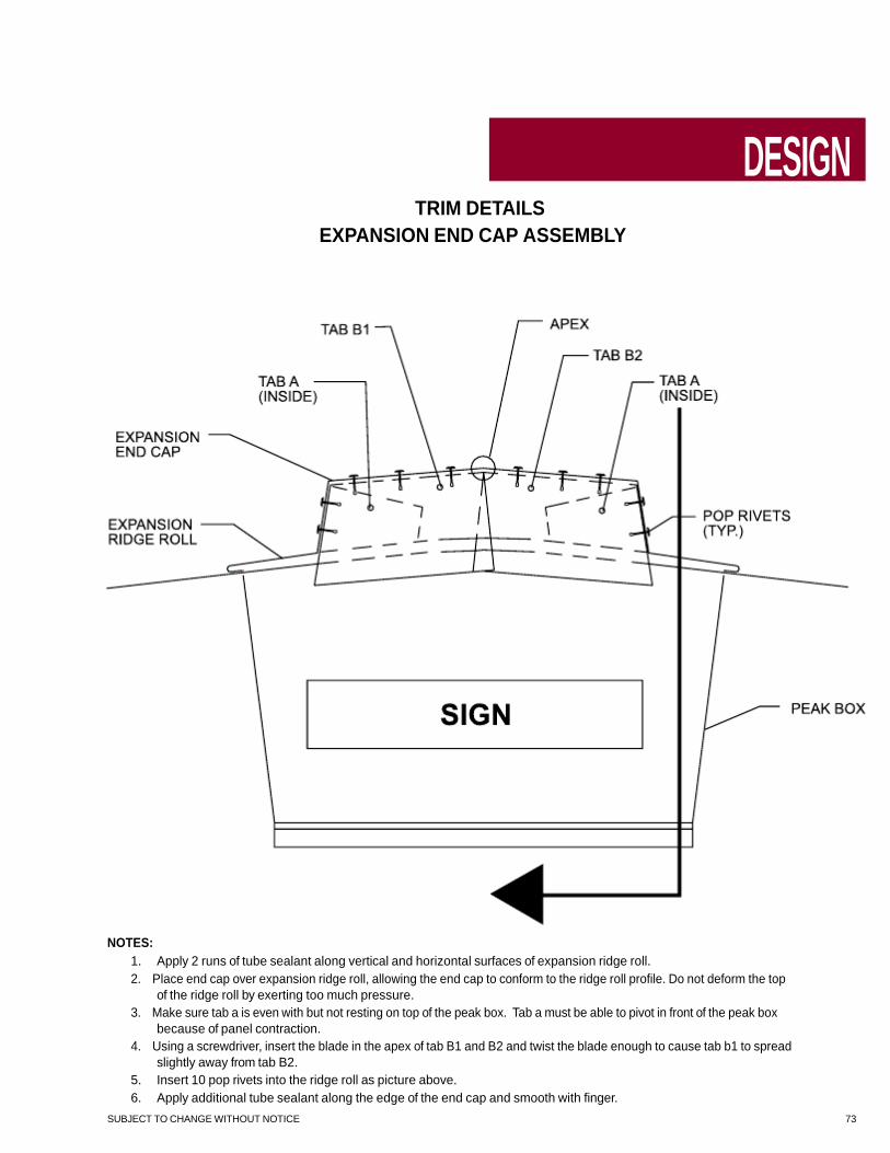
TRIM DETAILS
EXPANSION END CAP ASSEMBLY
DESIGN
NOTES: 1. Apply 2 runs of tube sealant along vertical and horizontal surfaces of expansion ridge roll. 2. Place end cap over expansion ridge roll, allowing the end cap to conform to the ridge roll profile. Do not deform the top
of the ridge roll by exerting too much pressure. 3. Make sure tab a is even with but not resting on top of the peak box. Tab a must be able to pivot in front of the peak box
because of panel contraction. 4. Using a screwdriver, insert the blade in the apex of tab B1 and B2 and twist the blade enough to cause tab b1 to spread
slightly away from tab B2. 5. Insert 10 pop rivets into the ridge roll as picture above. 6. Apply additional tube sealant along the edge of the end cap and smooth with finger.
SUBJECT TO CHANGE WITHOUT NOTICE 73
DESIGN
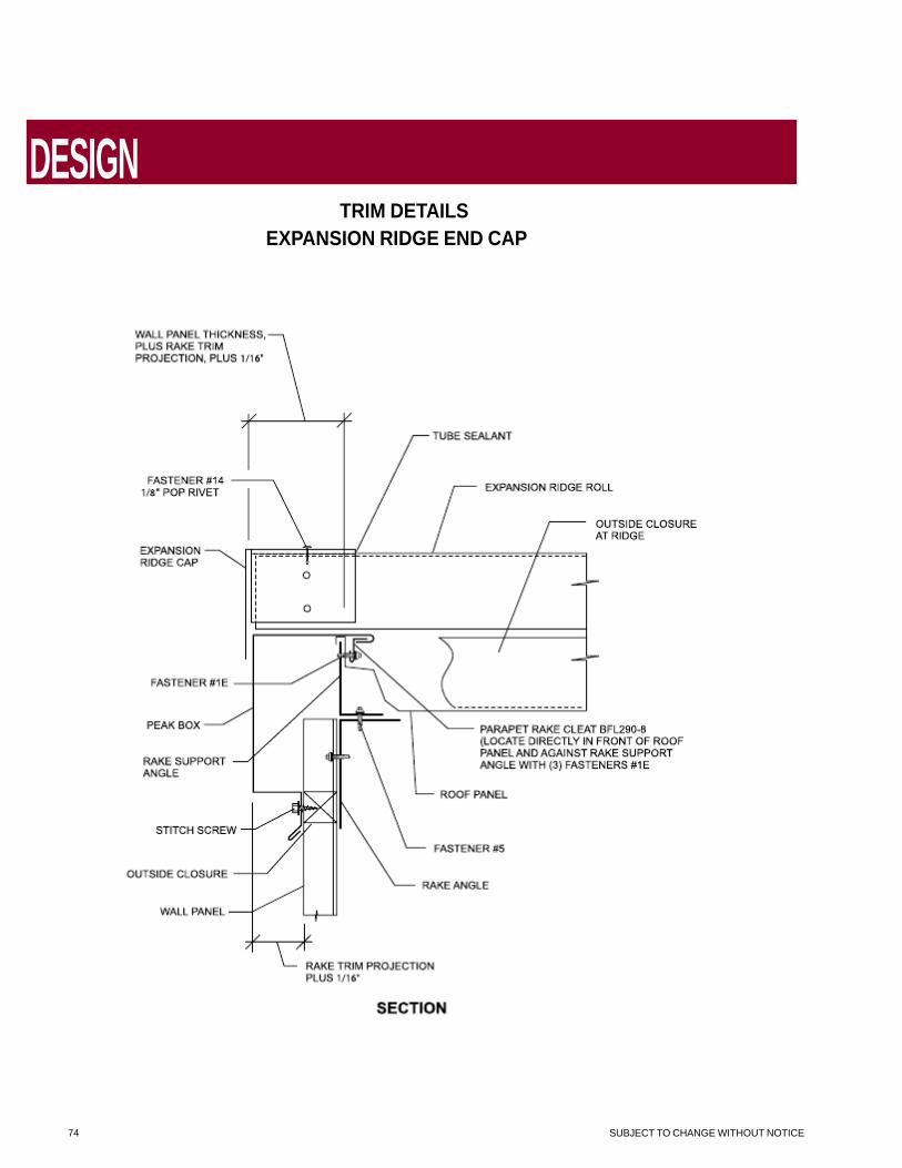
TRIM DETAILS
EXPANSION RIDGE END CAP
74 SUBJECT TO CHANGE WITHOUT NOTICE

TRIM DETAILS
FLOATING PEAK BOX
DESIGN
FLOATING PEAK BOX INSTALLATION
1. Install rake trim on each side of ridge to within 2” of centerline of building.
2. Install ridge flash so that it is on top leg of rake trim, 1” back from outside edge.
3. Temporarily set peak box in place and mark perimeter of box on rake trim and ridge flash. Remove peak box.
4. Just inside mark, install tape sealer continuously across ridge flash, then down the face of rake trim on both sides of ridge.
5. Place flexible membrane over tape sealer and hold in place with cinch angles. Cinch angles should be attached with Fastener #4. To prevent leaks, flexible membrane should be tight against ridge flash and rake trim with no wrinkles at the sealed edges.
6. Hook top of peak box over cinch angles installed on top of ridge flash and attach bottom of peak box to endwall with Fastener #4.
SUBJECT TO CHANGE WITHOUT NOTICE 75

DESIGN
TRIM DETAILS
RAKE
*Profile May Vary
SEE PAGES 16 AND 17 FOR FASTENER SELECTION. 76 SUBJECT TO CHANGE WITHOUT NOTICE
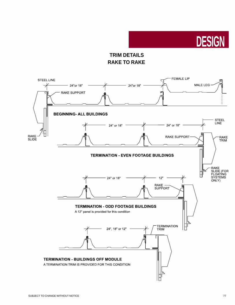
TRIM DETAILS
RAKE TO RAKE
DESIGN
SUBJECT TO CHANGE WITHOUT NOTICE 77

DESIGN
TRIM DETAILS
RAKE PARAPET
*Not by Building Manufacturer 78 SUBJECT TO CHANGE WITHOUT NOTICE

TRIM DETAILS
HIGH EAVE PARAPET
DESIGN
*Not by Building Manufacturer
NOTE: HIGH SIDE PURLIN IS 9” DOWN SLOPE
SUBJECT TO CHANGE WITHOUT NOTICE 79

DESIGN
TRIM DETAILS
EAVE
*Profile May Vary
NOTE: THIS OPTIONAL SCULPTURED EAVE TRIM IS AVAILABLE. HOWEVER, UNDER
CERTAIN CONDITIONS IT MAY INDUCE STAINING OF WALL PANELS. 80 SUBJECT TO CHANGE WITHOUT NOTICE

TRIM DETAILS
SNOW GUTTER
DESIGN
*Not by Building Manufacturer
NOTES: 1. Attach gutter to eave plate with Fastener #14A (3 fasteners per 10’ piece). 2. Install gutter straps 3’-0” O.C. 3. Apply Tri-Bead tape sealer to slope leg of gutter. 4. Use minor rib tape sealer to fill voids in panel at minor ribs as shown on page 35. 5. Install panel with Fastener #1E at prepunched holes. Panel must not overhang into gutter. 6. Front top edge of gutter must not project above the plane of the panel pan. 7. Gutter may not catch all water during heavy rains.
SUBJECT TO CHANGE WITHOUT NOTICE 81

DESIGN
TRIM DETAILS
10” DEEP GUTTER - FIXED EAVE
NOTE: Gutter may not catch all water during heavy rains.
82 SUBJECT TO CHANGE WITHOUT NOTICE

TRIM DETAILS
10” DEEP GUTTER - EXPANSION EAVE
DESIGN
NOTE: Gutter may not catch all water during heavy rains. SUBJECT TO CHANGE WITHOUT NOTICE 83
DESIGN
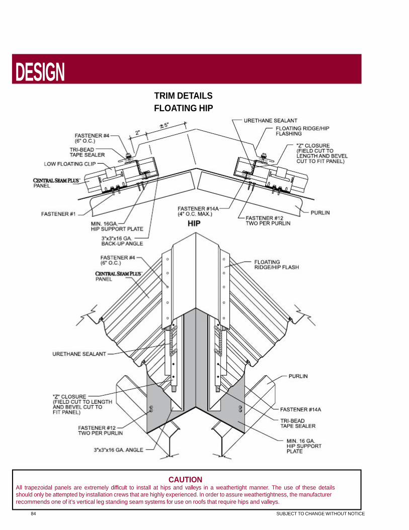
TRIM DETAILS
FLOATING HIP
CAUTION All trapezoidal panels are extremely difficult to install at hips and valleys in a weathertight manner. The use of these details should only be attempted by installation crews that are highly experienced. In order to assure weathertightness, the manufacturer recommends one of it’s vertical leg standing seam systems for use on roofs that require hips and valleys.
84 SUBJECT TO CHANGE WITHOUT NOTICE

TRIM DETAILS
VALLEY
DESIGN
CAUTION All trapezoidal panels are extremely difficult to install at hips and valleys in a weathertight manner. The use of these details should only be attempted by installation crews that are highly experienced. In order to assure weathertightness, the manufacturer recommends one of its vertical leg standing seam systems for use on roofs that require hips and valleys.
SUBJECT TO CHANGE WITHOUT NOTICE 85

GENERAL INFORMATION
PRODUCT CHECKLIST
Floating Peak Box
Sculptured Eave Trim
Specify Roof Pitch
Gutter
Note: For use with Ridge Flash.
Note: For use with Ridge Flash.
*Includes cinch angles and flexible membrane.
Rake Trim
High Side Eave Trim
Ridge Flashing
Specify Roof Pitch Specify Roof Pitch
86 SUBJECT TO CHANGE WITHOUT NOTICE
ROOF PITCH DIM. A NOTE
1/4-2 1/2:12 6 1/2” For use without ventilator
24” Peak purlin spacing 2 9/16-4:12 7 1/2”
1/4-2 1/2:12 10 1/4” For use with 9” ventilator
32” Peak purlin spacing 2 9/16-4:12 11”
ROOF PITCH DIM. A
1/4-4:12 6 5/16”
1/4-4:12 6 5/16”
4 1/4-6:12 6 15/16”
4 1/4-6:12 6 15/16”
ROOF PITCH DIM. A
1/4-1C\v:12 2”
2-4:12 3 11\16”

GENERAL INFORMATION
PRODUCT CHECKLIST
Gutter Strap
Sculptured Eave Corner Box
Mitered Sculptured Rake (Left or Right)
Mitered Sculptured High Side Eave (Left or Right)
Ridge End Cap
Rake Slide
Light Transmitting Panel Trim
Mitered Sculptured Gutter (Left or Right)
Perforated Vent Drip
Variable Termination
Flat Eave Trim
Offset Panel Cap Trim
24 Gauge Material 24 Gauge Material
SUBJECT TO CHANGE WITHOUT NOTICE 87

GENERAL INFORMATION
PRODUCT CHECKLIST
Standard Valley — Low and Utility Systems
Standard Valley — High System
Extended Valley — Low and Utility Systems
Extended Valley — High System
Parapet Rake Cleat
Counter Flash
Parapet High Side Eave Flash
Alternate Counter Flash
Parapet Rake Flash
24 Gauge Material 24 Gauge Material
88 SUBJECT TO CHANGE WITHOUT NOTICE

NOTES
