erosion and sedimentation control planfoxtownship.com/water system study hrg.pdf · section 2-...
TRANSCRIPT

200 West Kensinger Drive, Suite 400
Cranberry Township, PA 16066
(724) 779-4777
Fax (724) 779-4711
www.hrg-inc.com
SEPTEMBER 15, 2016
DRAFT
WATER SOURCE AND TREATMENT
EVALUATION STUDY
FOR
TOBY WATER SYSTEM
WATER ALLOCATION PERMIT NO. 96120
PWS ID NO. 6240008
FOX TOWNSHIP, ELK COUNTY, PENNSYLVANIA
HRG Project No. 001693.0435

WATER SOURCE AND TREATMENT EVALUATION STUDY
FOR
TOBY WATER SYSTEM
FOX TOWNSHIP
ELK COUNTY, PENNSYLVANIA
PREPARED FOR:
FOX TOWNSHIP
P.O. BOX 184
KERSEY, PENNSYLVANIA 15846
PREPARED BY:
HERBERT, ROWLAND & GRUBIC, INC.
200 WEST KENSINGER DRIVE, SUITE 400
CRANBERRY TOWNSHIP, PENNSYLVANIA 16066
(724) 779-4777
______________________________
Chad E. Hanley, P.E.

FOX TOWNSHIP, TOBY WATER SYSTEM
WATER SOURCE AND TREATMENT EVALUATION STUDY
TABLE OF CONTENTS
Subject Page
WATER SOURCE AND TREATMENT EVALUATION STUDY
INTRODUCTION ----------------------------------------------------------------------------------------------------- 1
SECTION 1- EXISTING FACILITIES OVERVIEW --------------------------------------------------------- 2
SECTION 2- DETERMINING RESERVOIR DESIGN CAPACITY -------------------------------------- 3
SECTION 3- RESERVOIR UPGRADES ------------------------------------------------------------------------ 4
SECTION 4- TREATMENT PLANT UPGRADES------------------------------------------------------------ 5
SECTION 5- INTERCONNECTION WITH ST. MARYS AWA ------------------------------------------- 5
APPENDICES
Appendix A: SYSTEM LOCATION MAP
Appendix B: DRAINAGE MAP
Appendix C: SOIL REPORT
Appendix D: RESERVOIR PRELIMINARY LAYOUT EXHIBITS
Appendix E: PRELIMINARY COST ESTIMATE AND PROJECT IMPLEMENTATION SCHEDULE
Appendix F: LAYOUT OF PRELIMINARY TREATMENT PLANT DESIGN

FOX TOWNSHIP, TOBY WATER SYSTEM
WATER SOURCE AND TREATMENT EVALUATION STUDY 1
WATER SOURCE AND TREATMENT EVALUATION STUDY
FOR
FOX TOWNSHIP
TOBY WATER SYSTEM
INTRODUCTION
Fox Township (Township) owns and operates the Toby Water System (System), which serves an estimated
population of 511 residents in Fox Township, Elk County, Pennsylvania. The water treatment plant (WTP)
was constructed in 1994 as the first Pennsylvania water treatment plant to employ membrane filtration for
drinking water treatment. The WTP’s raw water source is the Lost Run Reservoir (reservoir). Up until the
WTP ceased operation in December 2014 following a failed filter plant performance test, the system
required labor-intensive operation to maintain the aging equipment’s functionality. Since the WTP has
been shut down, the Township has been purchasing bulk water from the St. Marys Area Water Authority
under an emergency permit issued on December 17, 2014. The permit allowed for the continuous use of
and upgrade to the interconnection with the St. Marys Area Water Authority. The interconnection is still
currently in use and consists of a 2” metered connection.
A previous study prepared by Nittany Engineering & Associates, LLC examined other potential sources of
water and in general the only two feasible options to the Township are the St. Marys AWA interconnect or
an expansion to the existing Lost Run Reservoir and upgrade to the WTP. The Township has engaged
HRG, to perform a planning level study to determine the required upgrades to the existing reservoir and
WTP and provide cost estimates for those improvements.
It is also understood that the Pennsylvania Department of Environmental Protection (PADEP) is currently
drafting a Consent Order and Agreement (COA) that will likely include requirements for a study such as
this to be completed and therefore the Township is in a good position with advancing the completion of this
work. However, modifications or additions to this study may be required depending on the requirements
of the COA.

FOX TOWNSHIP, TOBY WATER SYSTEM
WATER SOURCE AND TREATMENT EVALUATION STUDY 2
SECTION 1- EXISTING FACILITIES OVERVIEW
The current operational design of the WTP is as follows: Raw water from the reservoir enters the WTP and
passes through a series of three (3) bag filters (Shelco, Model BFS-2C-2) and a sand/grit separator
(LAKOS). The pre-filtered water then enters a raw water storage tank with an approximate volume of
1,200 gallons. From the raw water tank, water is pumped through one of two membrane filtration process
trains, each containing a feed pump (60-90 psi), a 1-micron cartridge filter (Harmsco, Hurricane Model
HUR 170 HP) and spiral membrane filtration unit (GE Osmonics, Model JX4040F1052). Each membrane
unit contains seven (7) filter modules. After passing through the membrane units, the water is conveyed to
a 1,200-gallon filtered water tank where it is dosed with sodium hypochlorite for disinfection and sodium
silicate for corrosion control. The finished water is then pumped out of the filtered water tank to one of
four 20,000-galon Finished Water Storage Tanks. Locations of the reservoir, WTP and finished water
storage tanks are shown in Appendix A.
The Lost Run Reservoir is located on Sawmill Road in Fox Township. Based on an analysis of the USGS
topographic contours, the reservoir has a drainage area of approximately 475 acres (0.74 square miles) and
is predominantly fed by Tributary 50397 to Sawmill Run (Tributary), formerly known as Lost Run. See
Appendix B for a map of the drainage area. In November of 2012, Fox Township was granted a Water
Allocation Permit from the PADEP to allow a maximum withdrawal of 40,000 gallons per day (gpd) from
the reservoir. That permit does not require a conservation release from the reservoir. The reservoir was
originally built with an approximate capacity of 1.5 million gallons. Due to sediment build up, the current
storage volume is estimated at 670,000 gallons (per PADEP Filter Plant Performance Evaluation dated
November 17-19, 2014).
According to the DEP Public Drinking Water Reporting System, before the interconnection agreement with
St Marys Area Water Authority was set forth, the WTP served a population of approximately 511. Utilizing
the DEP PWS Design Manual, Part II, it can be estimated that 75 gallons of water are utilized per day per
capita. Therefore, the WTP should be able to provide, at minimum, 38,325 gpd. Based on the Nittany
Engineering report previously cited: “it is reasonable and prudent to recommend that the source of water
for the Fox Township water system be capable of providing a minimum of 39,900 gpd or 28 gpm.”. For
purposes of this study this amount will be rounded to 40,000 gpd.

FOX TOWNSHIP, TOBY WATER SYSTEM
WATER SOURCE AND TREATMENT EVALUATION STUDY 3
SECTION 2 – DETERMINATION OF RESERVOIR DESIGN CAPACITY
Conversations with PADEP personnel have indicated that if the reservoir is proposed to be put back in
service a new water allocation permit will be required. Further, it has been indicated that the new permit
will contain a conservation release requirement. Until the permit is completed, submitted and reviewed by
PADEP it can only be estimated what the rate of this conservation release requirement will be. In order to
estimate this release rate, HRG has utilized the Susquehanna River Basin Commission Policy No. 2012-01
Technical Guidance for Low Flow Protection Related to Withdrawal Approvals adopted in 2012. This
guidance document is relied upon by the PADEP to determine the release rates to protect watersheds during
low flow periods. The estimated passby flow (conservation release) requirement presented in this study was
determined in accordance with the referenced Commission Policy.
It is important to note that the tributary’s designated use according to the PADEP eMAPPA application is
High Quality-Cold Water Fishes (HQ-CWF). It is also designated as a Total Maximum Daily Load
(TMDL) stream and is considered impaired due to Atmospheric Deposition. Therefore, the DEP may
require additional passby flow protection.
The tributary meets Aquatic Resource Class (ARC) 1 because the drainage area is less than 10 square miles.
The percent exceedance flow specified for ARC 1 is 70 percent (%) of the 7-Day 10-Year Low Flow rate
(Q7-10). According to Pennsylvania StreamStats, the Q7-10 for the drainage area is 0.039 cubic feet per
second. This equates to 25,205 gallons per day (gpd). Therefore, the estimated required passby rate is
17,643 gpd when factoring in the 70% requirement.
In periods of drought, it has been observed that nearly zero water flows into the reservoir. During severe
drought years, this can occur for periods as long as sixty to ninety days. Therefore, in order to ensure that
the WTP has a source of water and that the conservation release requirement can be met, a significant
volume of water must be stored. To determine this maximum required storage volume, the following has
been assumed:
1. Required water for treatment is 40,000 gallons per day; because this is a max day usage, it has been
further assumed that this quantity is inclusive of required membrane backwash water.
2. The drought period utilized in sizing the reservoir is 90 days, to ensure that the reservoir is equipped
to provide water in the event of a 90-day drought.
3. Provide the conservation release of 18,000 gpd.
4. Provide 10% of unusable capacity so that the intake is not drawing from the bottom of the reservoir.
5. Evaporation quantity has been negated at this point in the study, however will need to be evaluated
in the preliminary design stage. Estimates of this quantity indicate this could be as much as 3
million gallons depending on the surface area of the reservoir.
6. Leakage has been negated at this point and it is assumed that an impermeable liner will be installed.
With consideration of the above assumptions, the reservoir storage capacity is estimated at 5.8 million
gallons.
Appendix D shows a draft plan and section of what a reservoir of this size would look like compared to the
existing reservoir.
This is nearly 4 times the original design capacity of 1.5 million gallons and approximately 8.5 times the
existing usable capacity of 670,000 gallons.
FOX TOWNSHIP, TOBY WATER SYSTEM
WATER SOURCE AND TREATMENT EVALUATION STUDY 4
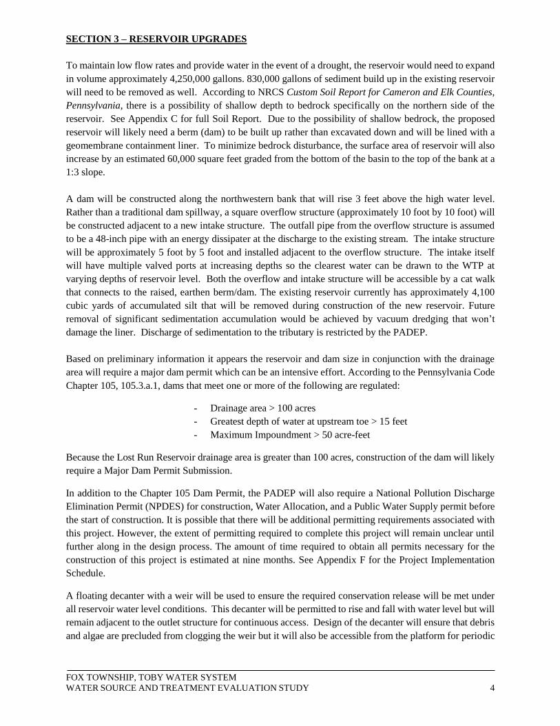
SECTION 3 – RESERVOIR UPGRADES
To maintain low flow rates and provide water in the event of a drought, the reservoir would need to expand
in volume approximately 4,250,000 gallons. 830,000 gallons of sediment build up in the existing reservoir
will need to be removed as well. According to NRCS Custom Soil Report for Cameron and Elk Counties,
Pennsylvania, there is a possibility of shallow depth to bedrock specifically on the northern side of the
reservoir. See Appendix C for full Soil Report. Due to the possibility of shallow bedrock, the proposed
reservoir will likely need a berm (dam) to be built up rather than excavated down and will be lined with a
geomembrane containment liner. To minimize bedrock disturbance, the surface area of reservoir will also
increase by an estimated 60,000 square feet graded from the bottom of the basin to the top of the bank at a
1:3 slope.
A dam will be constructed along the northwestern bank that will rise 3 feet above the high water level.
Rather than a traditional dam spillway, a square overflow structure (approximately 10 foot by 10 foot) will
be constructed adjacent to a new intake structure. The outfall pipe from the overflow structure is assumed
to be a 48-inch pipe with an energy dissipater at the discharge to the existing stream. The intake structure
will be approximately 5 foot by 5 foot and installed adjacent to the overflow structure. The intake itself
will have multiple valved ports at increasing depths so the clearest water can be drawn to the WTP at
varying depths of reservoir level. Both the overflow and intake structure will be accessible by a cat walk
that connects to the raised, earthen berm/dam. The existing reservoir currently has approximately 4,100
cubic yards of accumulated silt that will be removed during construction of the new reservoir. Future
removal of significant sedimentation accumulation would be achieved by vacuum dredging that won’t
damage the liner. Discharge of sedimentation to the tributary is restricted by the PADEP.
Based on preliminary information it appears the reservoir and dam size in conjunction with the drainage
area will require a major dam permit which can be an intensive effort. According to the Pennsylvania Code
Chapter 105, 105.3.a.1, dams that meet one or more of the following are regulated:
- Drainage area > 100 acres
- Greatest depth of water at upstream toe > 15 feet
- Maximum Impoundment > 50 acre-feet
Because the Lost Run Reservoir drainage area is greater than 100 acres, construction of the dam will likely
require a Major Dam Permit Submission.
In addition to the Chapter 105 Dam Permit, the PADEP will also require a National Pollution Discharge
Elimination Permit (NPDES) for construction, Water Allocation, and a Public Water Supply permit before
the start of construction. It is possible that there will be additional permitting requirements associated with
this project. However, the extent of permitting required to complete this project will remain unclear until
further along in the design process. The amount of time required to obtain all permits necessary for the
construction of this project is estimated at nine months. See Appendix F for the Project Implementation
Schedule.
A floating decanter with a weir will be used to ensure the required conservation release will be met under
all reservoir water level conditions. This decanter will be permitted to rise and fall with water level but will
remain adjacent to the outlet structure for continuous access. Design of the decanter will ensure that debris
and algae are precluded from clogging the weir but it will also be accessible from the platform for periodic

FOX TOWNSHIP, TOBY WATER SYSTEM
WATER SOURCE AND TREATMENT EVALUATION STUDY 5
maintenance and cleaning. The floating decanter will discharge the conservation release to the overflow
structure.
It is likely that an emergency spillway will not be necessary in the design of this reservoir because the
outfall structure will be designed to control the 100-year storm event. The proposed reservoir will not pose
a major threat to the downstream environment due to the size of the reservoir and the low height of the dam.
Estimated costs for the reservoir improvements are located in Appendix E.
SECTION 4-TREATMENT PLANT UPGRADES
The WTP upgrades are based on the 2009 Water Feasibility study completed by HRG. Adding pretreatment
to a membrane system that is 22 years old is not considered a viable option anymore. Based off the study
and the age of the existing water treatment plant the replacing the existing membrane filtration system with
a low pressure membrane system would be the best alternative.
In addition, algae growth in the reservoir in the summer months is a problem. The new reservoir would be
designed for greater depths and modifying the design of the intake to the water plant will help with algae
clogging the membranes but will not eliminate the problem. To further reduce the algae issue, the
installation of ultrasonic transducers or solar powered mixers in the reservoir will help reduce the amount
of algae blooms in the summer months. The WTP would also include a hydrogen peroxide chemical feed
system to help prevent fouling of the membranes due to iron and manganese. Pretreatment filtering and
settling will also be examined.
Treatment of the backwash water from the membranes may also be required. HRG continues to investigate
this with PADEP to determine the discharge limits that will be imposed.
The existing WTP building will be expanded and rehabilitated. An approximate 12 foot extension to the
building is proposed with a new loading dock to provide improved access to the treatment unit area and
space for chemical storage. New electrical equipment and general building rehabilitation is also anticipated.
According to a preliminary, budget proposal for the package treatment plant provided by Evoqua Water
Technologies, LLC, and Artesian of Pioneer Water Treatment Systems, the cost of the proposed treatment
system is estimated at $350,000. The proposed 2 skid system includes two 40,000 gpd units. See Appendix
F for a suggested layout with an elevation view drawing provided by Evoqua Water Technologies, LLC.
The total cost for the WTP upgrades is estimated at $1.38 million
SECTION 5- INTERCONNECTION WITH ST. MARYS AREA WATER AUTHORITY
An emergency permit was issued on December 17, 2014 for the use of an upgraded interconnection with
the Saint Marys Area Water Authority (St. Marys). This interconnection has been in use since the permit
was issued. The interconnection consists of a 2” meter, 2” piping and associated valving. The
interconnection is manually operated to fill the existing 80,000 gallon storage tanks and/or to supply water
to the Fox Township distribution system on an as-needed basis.
The Water System Feasibility Study/Report by Nittany Engineering & Associates, LLC completed in
February of 2016 analyzed the possibility of a long-term interconnection with St. Marys. The report
disregards long-term utilization of the existing interconnection due to the need to manually open and close
the valves at the interconnect to affect turnover within the 80,000 gallon storage tanks.
For the interconnection to become a permanent solution, upgrades to the existing system will need to be
made. The extent of these upgrades and associated costs are currently unknown but it can safely be
anticipated that a permanent interconnection with St. Marys will be a lower cost alternative and therefore
other factors concerning the system should be considered.
In general, if the interconnect is to be utilized long-term, there are few concerns that need to be addressed
by either St. Marys Water Authority, the Township or both:
- Study the effects of water age on the Township’s system including turnover within
the storage tanks and the effect of Disinfection By-Products (DBP).
- Constructing more robust interconnection with larger diameter pipe and automated
valves.
- In-depth study of St. Marys system and the long term capital improvements that
should be made in that system to support demand. This may include watermain
replacement or additional, expanded storage and re-chlorination facilities.
- Other issues that may arise during investigation and preparation of these studies.

APPENDIX A
SYSTEM LOCATION MAP


APPENDIX B
DRAINAGE MAP


APPENDIX C
SOIL REPORT
SOIL REPORT NOT
INCLUDED

APPENDIX D
RESERVOIR PRELIMINARY DESIGN EXHIBITS


APPENDIX E
PRELIMINARY COST ESTIMATE AND PROJECT
IMPLEMENTATION SCHEDULE

200 WEST KENSINGER DRIVE
SUITE 400
CRANBERRY TOWNSHIP, PA 16066
ITEM NO. DESCRIPTION EST QTY UNIT UNIT COST TOTAL COST
1 NEW MEMBRANE FILTRATION 1 LS 350,000.00$ 350,000.00$
2 H2O2 OXIDATION SYSTEM 1 LS 3,500.00$ 3,500.00$
3 ULTRASONIC ALGEA CONTROL 3 EA 8,500.00$ 25,500.00$
4 MISC EQUIPMENT AND CONTROLS 1 LS 75,000.00$ 75,000.00$
5 BUILDING EXTENTION 1 LS 50,000.00$ 50,000.00$
6 MISC BUILDING REHAB 2 LS 30,000.00$ 60,000.00$
7 PIPING AND ELECTRICAL 1 LS 80,000.00$ 80,000.00$
8 LOADING DOCK 1 LS 25,000.00$ 25,000.00$
9 BACKWASH TREATMENT 1 LS 80,000.00$ 80,000.00$
10 DEMO 1 LS 40,000.00$ 40,000.00$
SUBTOTAL 789,000.00$
INSTALLATION 25% 197,250.00$
SUBTOTAL 986,250.00$
CONTINGENCY 20% 197,250.00$
ESTIMATE CONSTRUCTION COST 1,183,500.00$
DESIGN 95,000.00$
PERMITTING 30,000.00$
PILOT TESTING/LABORATORY 45,000.00$
LEGAL AND ADMINISTRATION 3,000.00$
CONSTRUCTION PHASE SERVICES 10% 118,400.00$
TOTAL 1,380,000.00$
TREATMENT PLANT COST ESTIMATE
200 WEST KENSINGER DRIVE
SUITE 400
CRANBERRY TOWNSHIP, PA 16066
ITEM NO. DESCRIPTION EST QTY UNIT UNIT COST TOTAL COST
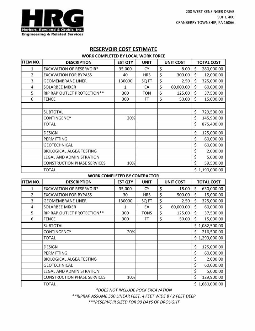
1 EXCAVATION OF RESERVOIR* 35,000 CY 8.00$ 280,000.00$
2 EXCAVATION FOR BYPASS 40 HRS 300.00$ 12,000.00$
3 GEOMEMBRANE LINER 130000 SQ FT 2.50$ 325,000.00$
4 SOLARBEE MIXER 1 EA 60,000.00$ 60,000.00$
5 RIP RAP OUTLET PROTECTION** 300 TON 125.00$ 37,500.00$
6 FENCE 300 FT 50.00$ 15,000.00$
SUBTOTAL 729,500.00$
CONTINGENCY 20% 145,900.00$
TOTAL 875,400.00$
DESIGN 125,000.00$
PERMITTING 60,000.00$
GEOTECHNICAL 60,000.00$
BIOLOGICAL ALGEA TESTING 2,000.00$
LEGAL AND ADMINISTRATION 5,000.00$
CONSTRUCTION PHASE SERVICES 10% 59,500.00$
TOTAL 1,190,000.00$
ITEM NO. DESCRIPTION EST QTY UNIT UNIT COST TOTAL COST
1 EXCAVATION OF RESERVOIR* 35,000 CY 18.00$ 630,000.00$
2 EXCAVATION FOR BYPASS 30 HRS 500.00$ 15,000.00$
3 GEOMEMBRANE LINER 130000 SQ FT 2.50$ 325,000.00$
4 SOLARBEE MIXER 1 EA 60,000.00$ 60,000.00$
5 RIP RAP OUTLET PROTECTION** 300 TONS 125.00$ 37,500.00$
6 FENCE 300 FT 50.00$ 15,000.00$
SUBTOTAL 1,082,500.00$
CONTINGENCY 20% 216,500.00$
TOTAL 1,299,000.00$
DESIGN 125,000.00$
PERMITTING 60,000.00$
BIOLOGICAL ALGEA TESTING 2,000.00$
GEOTECHNICAL 60,000.00$
LEGAL AND ADMINISTRATION 5,000.00$
CONSTRUCTION PHASE SERVICES 10% 129,900.00$
TOTAL 1,680,000.00$
***RESERVOIR SIZED FOR 90 DAYS OF DROUGHT
RESERVOIR COST ESTIMATE
**RIPRAP ASSUME 500 LINEAR FEET, 4 FEET WIDE BY 2 FEET DEEP
*DOES NOT INCLUDE ROCK EXCAVATION
WORK COMPLETED BY LOCAL WORK FORCE
WORK COMPLETED BY CONTRACTOR

200 WEST KENSINGER DRIVE
SUITE 400
CRANBERRY TOWNSHIP, PA 16066
DESCRIPTION EST QTY UNIT UNIT COST TOTAL COST
CONCRETE 65 CY 1,500.00$ 97,500.00$
48 INCH PIPE COST 100 FT 150.00$ 15,000.00$
6 INCH PIPE 200 FT 50.00$ 10,000.00$
CATWALK AND GRATING 1 LS 10,000.00$ 10,000.00$
VALVES/ MISC 1 LS 15,000.00$ 15,000.00$
FLOATING DECANTER 1 LS 75,000.00$ 75,000.00$
RIP RAP ENERGY DISSIPATER 1 LS 50,000.00$ 50,000.00$
EARTH DAM 1 LS 350,000.00$ 350,000.00$
SUB TOTAL 622,500.00$
CONTINGENCY 15 % 93,375.00$
TOTAL 715,875.00$
ENGINEERING 40,000.00$
LEGAL AND ADMINISTRATION 4,000.00$
CONSTRUCTION PHASE SERVICES 10 % 71,600.00$
TOTAL 760,000.00$
OUTFALL COST ESTIMATE

200 WEST KENSINGER DRIVE
SUITE 400
CRANBERRY TOWNSHIP, PA 16066
LOCAL FORCES CONTRACTOR
1,380,000.00$ 1,380,000.00$
1,190,000.00$ 1,680,000.00$
760,000.00$ 760,000.00$
3,330,000.00$ 3,820,000.00$
TOTAL COST COMPARISON
TREATMENT COST
RESERVOIR COST
DAM AND OUTFALL COST
TOTAL

Toby Water System Evaluation
Task Name Duration Start Date Finish Date
Design
Water Treatment Plant Design 245 Days 1-Jan-17 1-Sep-17
Reservoir Design 245 Days 1-Jan-17 1-Sep-17
Geotechnical Investigation 60 Days 1-Mar-17 29-Apr-17
Permitting
Chapter 105 Dam Permit 180 Days 1-Jun-17 7-Dec-17
NPDES Submission 60 Days 1-Aug-17 1-Oct-17
Water Quality Management Permit 180 Days 1-Jun-17 7-Dec-17
Water Allocation Permit 180 Days 1-Jun-17 7-Dec-17
Public Water Supply Permit 180 Days 1-Jun-17 7-Dec-17
Address Review Comments 30 Days 7-Dec-17 6-Jan-18
Obtain Permits 30 Days 6-Jan-18 6-Feb-18
Bidding
Advertise for Bids 30 Days 20-Mar-18 17-Apr-18
Review and Award Construction Contracts 60 Days 17-Apr-18 17-Jun-18
Construction
Construction of Treatment Plant 365 Days 16-Aug-18 16-Aug-19
Construction of Reservoir 275 Days 16-Aug-18 15-May-19
Start-up of Water Treatment Plant 30 Days 16-Aug-19 16-Sep-19Time to Fill Reservoir* 90 Days 15-May-19 13-Aug-19
Project Implementation Schedule
*Time to fill reservoir will vary depending on rainfall accumulation and frequency.

APPENDIX F
LAYOUT OF PRELIMINARY TREATMENT PLANT DESIGN

PRELIMINARYNOT FOR CONSTRUCTION
COMPRESSORSAIR RECEIVERS
STRAINERS
CIP TANK
NEUTRALIZATION TANKCHEMICAL DRUMS
CONTROL PANELS
XPsr UNIT
DATE
STATUS
DATE
DRAWN
CHECKED
SCALE:
DATE TITLE
PROJECT DRAWING SHEET
APPROVED
U.S.A. ECRDESCRIPTION DATE DWN CHKD APVD
GENERAL ARRANGEMENT
MEMCOR 1 X 12XP
MEMCOR STANDARD
OF
6/2/2011
6/2/2011
U.S.A.55 TECHNOLOGY DRIVE, SUITE 201LOWELL,MA 01851-5203
1-800-636-2674 (1-800-MEMCOR4)
U.K.OUTRAMS WHARF.LITTLE EATON,DERBY. ENGLAND, DE21 5ELTEL +44 (0) 1332 387300
ALL DIMENSIONS
IMPERIAL
DO NOT SCALE
AUSTRALIA1 MEMTEC PARKWAY,SOUTH WINDSOR.NSW 2756
TEL +61 (0) 2 4577 6800
CLIENT6/2/2011
U.K./AUS 9200770552-GANONE 1 2 A920077
SML
SJT
PRELIMINARY ISSUE6/2/11 SML SJT SJT
SJT
C:\Vault 2008\Prospects\XP Plant Layouts\1 x 12XPsr\9200770552-GA.idw
A
1
1
2
2
3
3
4
4
5
5
6
6
7
7
8
8
A A
B B
C C
D D

PRELIMINARYNOT FOR CONSTRUCTION
1'-6"
5'-2"
11'-2"
4'-2"5'-9"
3'-0"
4'-3"
2'-1
0"
10'-0
"
5'-2
"4'
-1"
9'-1
"
1'-6
"
8'-0
"
23'-0
"
1'-0
"
6'-1
"
28'-0"
3'-8
"
4'-3
"
7'-2
"
3'-2
" 5'-0
"6'-6
"7'-5
"
DATE
STATUS
DATE
DRAWN
CHECKED
SCALE:
DATE TITLE
PROJECT DRAWING SHEET
APPROVED
U.S.A. ECRDESCRIPTION DATE DWN CHKD APVD
GENERAL ARRANGEMENT
MEMCOR 1 X 12XP
MEMCOR STANDARD
OF
6/2/2011
6/2/2011
U.S.A.55 TECHNOLOGY DRIVE, SUITE 201LOWELL,
MA 01851-52031-800-636-2674 (1-800-MEMCOR4)
U.K.OUTRAMS WHARF.LITTLE EATON,DERBY. ENGLAND, DE21 5EL
TEL +44 (0) 1332 387300
ALL DIMENSIONSIMPERIAL
DO NOT SCALE
AUSTRALIA1 MEMTEC PARKWAY,SOUTH WINDSOR.
NSW 2756TEL +61 (0) 2 4577 6800
CLIENT6/2/2011
U.K./AUS 9200770552-GANONE 2 2 A920077
SML
SJT
PRELIMINARY ISSUE6/2/11 SML SJT SJT
SJT
C:\Vault 2008\Prospects\XP Plant Layouts\1 x 12XPsr\9200770552-GA.idw
A
1
1
2
2
3
3
4
4
5
5
6
6
7
7
8
8
A A
B B
C C
D D

PRELIMINARYNOT FOR CONSTRUCTION
1'-6"
5'-2"
11'-2"
4'-2"5'-9"
3'-0"
4'-3"
2'-1
0"
10'-0
"
5'-2
"9'
-1"
1'-6
"
8'-0
"
23'-0
"
1'-0
"
6'-1
"
33'-3"
DATE
STATUS
DATE
DRAWN
CHECKED
SCALE:
DATE TITLE
PROJECT DRAWING SHEET
APPROVED
U.S.A. ECRDESCRIPTION DATE DWN CHKD APVD
GENERAL ARRANGEMENT
MEMCOR 1 X 12XP
MEMCOR STANDARD
OF
6/2/2011
6/2/2011
U.S.A.55 TECHNOLOGY DRIVE, SUITE 201LOWELL,MA 01851-52031-800-636-2674 (1-800-MEMCOR4)
U.K.OUTRAMS WHARF.
LITTLE EATON,DERBY. ENGLAND, DE21 5ELTEL +44 (0) 1332 387300
ALL DIMENSIONSIMPERIAL
DO NOT SCALE
AUSTRALIA1 MEMTEC PARKWAY,SOUTH WINDSOR.NSW 2756TEL +61 (0) 2 4577 6800
CLIENT6/2/2011
U.K./AUS 9200770552-GANONE 2 2 A920077
SML
SJT
PRELIMINARY ISSUE6/2/11 SML SJT SJT
SJT
C:\Vault 2008\Prospects\XP Plant Layouts\1 x 12XPsr\9200770552-GA.idw
A
1
1
2
2
3
3
4
4
5
5
6
6
7
7
8
8
A A
B B
C C
D D
3'-0"