error correction in macro bar code symbols
TRANSCRIPT

US 20020088865A1
United States (19)
(12) Patent Application Publication (10) Pub. N0.: US 2002/0088865 A1 HE et al. (43) Pub. Date: Jul. 11, 2002
(54) ERROR CORRECTION IN MACRO BAR Related US. Application Data CODE SYMBOLS
(63) Continuation of application No. 09/014,482, ?led on (76) Inventors: DUANFENG HE, FARMINGVILLE, Jan. 28, 1998, noW patented.
NY (US); KEVIN HUNTER, EAST SETAUKET, NY (US); STEPHEN J , Publication Classi?cation SHELLHAMMER, LAKE GROVE, 7 NY (Us); SUNDEEP KUMAR, PORT (51) Int. Cl. .................................................. .. G06K 19/06 JEFFERSON, NY (Us) (52) US. Cl. ............................................................ .. 235/494
Correspondence Address: G ROGER LEE (57) ABSTRACT FISH & RICHARDSON P C 225 FRANKLIN STREET _ _ _ _
BOSTON MA 021102804 Adata encoding/decoding scherne includes a plurality of bar ’ code symbols each carrying a portion of the data in Which
( * ) Notice; This is a publication of a Continued pros- improved error correction capabilities are incorporated. ecution application (CPA) ?led under 37 According to one aspect, once data codewords have been CFR 1_53(d)_ derived to form the symbols, a ?rst set of data correction
elements are derived from a ?rst ?eld, then a second set of (21) Appl, N()_j 09/468,185 error correction elements are derived from the data elements
and the ?rst set of error correction elernents using a second, (22) Filed: Dec. 21, 1999 Wider ?eld.
LEFT ROW DATA CODE- RIGHT ROW TNDICATORS WORD AREA INDICATORS
’ 1
L0 dn-1 dn-2 4 R0
‘L1 R1
S T s A T R D T ~ P
Lm-2 d0 Ck-t Ck-E Rm-2
Lm-1 \ C1 C0 Rm-1 \ERRoR CORRECTION AREA
Patent Application Publication Jul. 11, 2002 Sheet 1 0f 12 US 2002/0088865 A1
(MODULE; 12 3 4 567891011121314151617 ll ll Illlll'lllllll
FIG. 1 <
ELEMENT WIDTH 5 1 1 1 1 1
X0 X2 X4 x6 x7
FIG. 4

Patent Application Publication Jul. 11, 2002 Sheet 2 0f 12 US 2002/0088865 A1
FIG. 2
LEFT ROW DATA CODE- RIGHT ROW ?NDICATORS WORD AREA INDICATORS
L0 dn-I dn-2 ) ‘ Ro
L1 H1
§ 5 A T R O T g P
Lm-z do (Ix-1 Ck-2 Rm-z
Lm-I \ C1 C0 Rm \ERROR CORRECTION AREA
FIG. 3
PDF417 SECURITY LEVEL
SECURITY LEVEL ERROR CORRECTION CODEWORDS
O 0 1 2
2 6 3 14
4 3O
5 62 6 126 7 254 8 510
Patent Application Publication Jul. 11, 2002 Sheet 4 0f 12 US 2002/0088865 A1
I ilJ ill ilJ n. im I al‘j? u. an I dun.‘ ,,, dl‘n I
F0). 501
go; 52
L Data Coduwocda Macro PDF Secure Macro ECC codeword! Control POF Field
Data Symbol II
Data Symbol it 2
Data Symbol if N
ECC Symbol 4| 1
ECC Symbol 0 2
ECC Symbol # M
Figure Secure Macro PDF417 Array Layout
Patent Application Publication Jul. 11, 2002 Sheet 5 0f 12 US 2002/0088865 A1
L Secure Macro POI-‘417 mm Data codewords
Data Symbol #1
om Symbol r 2
0m Symbol # 2
Dal: Symbol 6 4
Figure Sq- Varlable-Lenglh Symbols As Originally Encoded
L Secure Mm Data codewords POI-‘M7 D8!
Duh Symbol M
on- Symbol I 2
am Symbol 0 2
Data Symbol I 4
Eco Symbol r1 4‘
Ecc Symbol r2 4'
Figure 8&- Varlable-Length Symbols As Arranged for Cross-Symbol ECC
mm
mm
in ?C

Patent Application Publication Jul. 11, 2002 Sheet 6 0f 12 US 2002/0088865 A1
L Socuru Mam) Dal: codewords ECO codeword: PDF417 Data
Data Symbol 41
um Symbol 0 2
Duh Symbol I 2
Data Symbol I 4
Ecc Symbol 0 1
sec Symbol I 2
Figure 4- Variable-Length Symbol Set As Printed
Dal: codeword Am 1
dn-I do-I {
do cm ck-l
‘ ; =1 c.
\Emr Correction Nu

Patent Application Publication Jul. 11, 2002 Sheet 7 0f 12 US 2002/0088865 A1
Figure Omnidirectional 1D Scanning Pattern
PDF417 Locatcr System
no: 51811 X Om- S-qnu smmmmg X THE W Coordinate
Filter lmarpolalor Model Ust
Model to“ Fun" I PDF417 Penna
Position
v on» $09“! Smiling v’. - slop l ——-‘ Fillet lnlemolator m. °°°'°“, “m
Model Us: 1.
Figure I? Block Diagram of PDF417 Locator System
Patent Application Publication Jul. 11, 2002 Sheet 8 0f 12 US 2002/0088865 A1
XI"! A b ‘ yin]
(
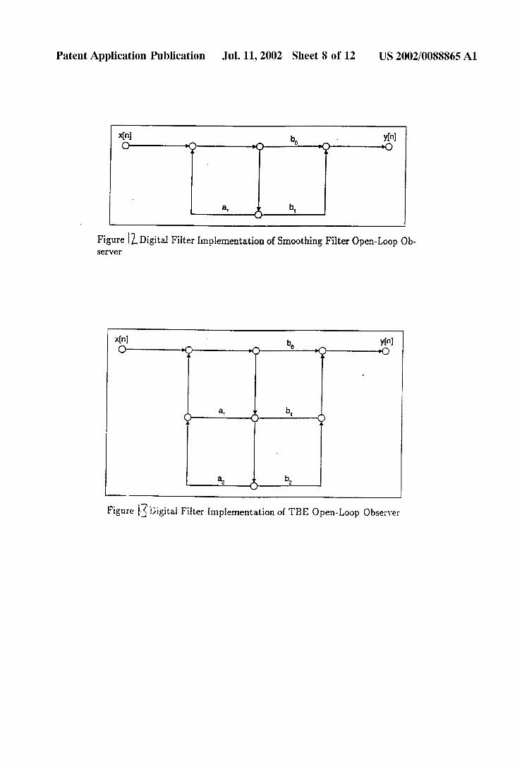
Figure llDigital Filter Implementation of Smoothing Filter Open~Loop Ob server
Xln] ' b Yin]
O a? =5) 0 ‘(1? =0
QF a’ 5p b‘ £2
a2 )K b2
Figure Digital Filter Implementation of THE Open-Loop Observer

Patent Application Publication Jul. 11, 2002 Sheet 9 0f 12 US 2002/0088865 A1
Figure (‘j-The Two Lines Along the Start and Stop Patterns of the PDF417 Label
Patent Application Publication Jul. 11, 2002 Sheet 10 0f 12 US 2002/0088865 A1
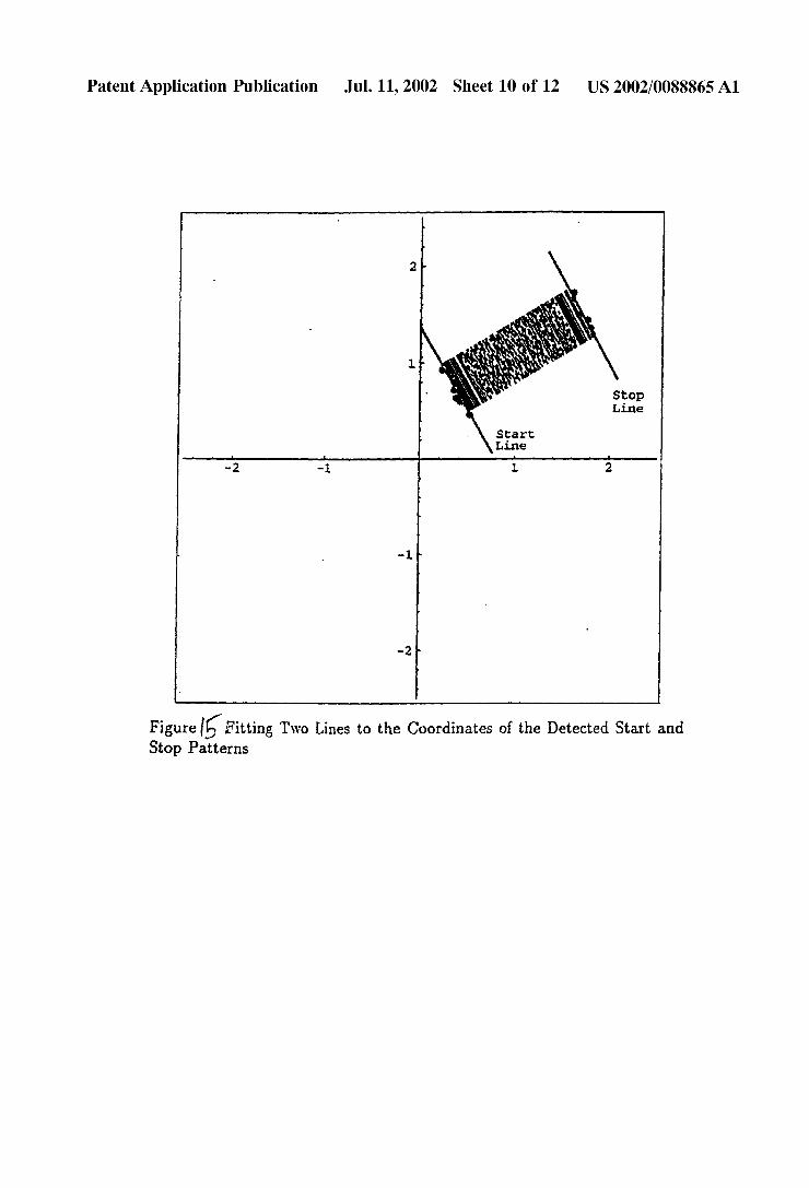
Figure Fitting Two Lines to the Coordinates of the Detected Start and Stop Patterns

Patent Application Publication Jul. 11, 2002 Sheet 11 0f 12
412
Input Information
to be encoded
Convert information into data codewords
£2
Add size codeword to data codewords
i)
Divide data codewords into N sections
Compute and add sectional error correction
codewords
£7.
Stagger data codewords
L0
Compute and add global error correction
codewords
FIG. ‘ 16
US 2002/0088865 A1

Patent Application Publication Jul. 11, 2002 Sheet 12 0f 12 US 2002/0088865 A1
Global wor uorredlon W
US 2002/0088865 A1
ERROR CORRECTION IN MACRO BAR CODE SYMBOLS
[0001] The present invention relates generally to error correction in macro bar code symbols.
[0002] This invention further relates generally to the opti cal scanning of tWo dimensional bar code symbols and in particular to the optical scanning of a randomly oriented tWo-dimensional bar code symbol by ?rst determining the orientation of the symbol With respect to the ?eld of vieW of the scanning device and then rotating the ?eld of vieW accordingly so as to be aligned substantially With the symbol for scanning and further processing and decoding as knoWn from US. Pat. No. 5,523,552 incorporated herein by refer ence. “Macro” bar code symbols alloW large documents to be encoded into multiple symbols, preferably tWo-dimen sional symbols. If one of those symbols is lost it may not be possible to recreate the document; this cannot be remedied by adding more error correction code Words into the indi vidual symbols.
[0003] The invention further addresses problems With knoWn error correction systems, in particular Where data is encoded across a plurality of symbols using a “macro” code. In knoWn systems, there can be a very high time penalty Where individual symbols are lost.
[0004] The invention further relates to decoding bar code symbols in Which the error correction capability alloWs the user to prioritise the importance of the codeWords Within a symbol.
[0005] The use of encoded data placed on certain types of records is advantageous in that a large amount of informa tion can be placed in a relatively small area.
[0006] Also, encoded information can be kept con?dential and revealed only to person having the appropriate decoding apparatus.
[0007] KnoWn records that could best utiliZe the bene?ts of having encoded data placed thereon are records Where the data does not change over the life of the record; or Where there are relatively large time gaps before the record or such encoded data become outdated. In such systems such records, Which include price tags, package identi?ers, or train car identi?ers for example, do not require frequent updating of the data. Another alternative Was to make the record large enough to accommodate additional encoded data representations for supplementing the information from time to time.
[0008] There are several types of records Where the ben e?ts of having encoded data thereon Were offset by the necessity of frequent updating of the encoded information. For example, health cards and records could bene?cially include encoded data because they required large amounts of necessary information and the need for con?dentiality. Charge cards, Where the remaining available credit could be printed on the card as each purchase is made, could bene? cially include encoded data. Admission tickets useful for multiple events could include the used or unused events as encoded data on the ticket. This Would include tickets for seminars With several Workshops, or an admission ticket to an amusement park that includes several rides and shoWs. In all of the above instances, the necessity of frequent updating of the encoded information Would either result in an over
Jul. 11, 2002
siZed cumbersome record, or the frequent replacement of the record With a neW record having updated encoded data.
[0009] One proposed solution to this set out in commonly assigned hereWith comprises a record Which contains a printed portion placed on the record and an information portion including removable information encoded in an error-correctable, machine-readable format.
[0010] A printer system for a record containing text in at least a portion thereof, comprises input means for receiving information to be placed onto the record; encoding means, coupled to the input means, for encoding the received information in an error-correctable, machine-readable for mat; and output means, coupled to the coding means, including means for removing any encoded information other than the received information from a record, and means for removably placing the encoded information on the record.
[0011] A reader system for a record having an information area containing removable information encoded in an error correctable format and text, comprises reading means for extracting the information from the information area; cor rection means, coupled to the reading means, for performing error correction on the removable information to correct any errors in the extracted information and output.
[0012] According to another aspect, bar codes have become broadly accepted as a means for automatically identifying objects. Abar code symbol is a pattern of parallel bars and spaces of various Widths that represent data ele ments or characters. The bars represent strings of binary ones and the spaces represent strings of binary Zeros. Gen erally, the bars and spaces can be no smaller than a speci?ed minimum Width Which is called a “module” or “unit”. The bars and spaces are multiples of this module siZe or mini mum Width.
[0013] The conventional bar code symbol is “one-dimen sional” in that the bars and spaces extend only in a single direction. There has been an increasing need, hoWever, for machine-readable symbols that contain more information than conventional bar code symbols. One approach for increasing the information in machine-readable symbols is to reduce the height of the bar codes and stack the bar codes one on top of each other to create a “stacked” or “tWo dimensional” bar code. One such tWo-dimensional bar code is PDF417, Which Was developed by Symbol Technologies, Inc. The PDF417 symbology utiliZes a variable number of codeWords Which are discrete representations of data. A complete description of the PDF417 code is contained in US. Pat. No. 5,304,786, Which is assigned to the same assignee as the present invention and Which is incorporated by reference herein. Other tWo dimensional bar code sym bologies include Code 1 and Maxicode, Which are referred to as matrix codes.
[0014] Both one-dimensional and tWo-dimensional bar code symbols are typically read by optical scanning tech niques, such as scanning laser beams, and the resulting electrical signals are then decoded to recover the date encoded in the symbol. In particular, tWo-dimensional bar codes symbols such as those in the PDF417 symbology are advantageously scanned by a tWo-dimensional mastering laser pattern, Which is comprised of a series of horiZontal scans repeatedly sWept in a vertical direction, as described
US 2002/0088865 A1
in US. Pat. Nos. 4,816,661 and 5,235,167, Which patents are assigned to the assignee of the present application and are incorporated by reference herein. When scanning and decoding a tWo-dimensional bar code symbol, hoWever, the horizontal scan lines of the laser raster must be aligned substantially With the horiZontal roWs of the symbol, usually Within :30. The laser scan lines form a ?eld of vieW and are parallel With the horiZontally located roWs of a PDF417 symbol, Which Will alloW successful decoding.
[0015] HoWever, the symbol tilted With respect to the scan lines in the ?eld of vieW such that the symbol cannot be successfully decoded. Although a tWo-dimensional bar code such as PDF417 alloWs some deviation, the orientation of the ?eld of vieW must still be less than some maximum angle relative to the roWs of the symbol.
[0016] When using a hand-held laser rastering scanner, it is fairly simple for the operator to physically align the raster pattern in the ?eld of vieW With the tWo-dimensional symbol by rotating the reader and/or the object bearing the symbol until the requisite alignment of the ?eld of vieW is obtained visually and the symbol is successfully read and decoded. There are many applications, hoWever, in Which it is desir able to be able to read and decode a tWo-dimensional bar code symbol that may be randomly oriented Without having to manually move the reader such that the ?eld of vieW is aligned With roWs of the symbol. For example, in an industrial environment, the symbol may be located on an object moving along a conveyor belt Where the reader vieWs the symbol from above. Thus, the symbol may be in any orientation relative to the ?eld of vieW of the reader. In addition, in a retail point-of-sale environment, the symbol may be located on an item presented to a cashier for purchase. The cashier typically puts the item bearing the symbol under a presentation scan lamp, Which provides the appropriate laser scanning pattern. It is thus desirable in this situation to alloW the cashier to quickly present the item under the scan lamp Without having to al-an the symbol With the raster pattern.
[0017] Bar code symbol reading devices are also knoWn in the art Which are based upon charge coupled device (CCD) imaging technology. For example, a tWo dimensional CCD array comprised of 512x512 elements may be used to capture an image for the entire target bar code symbol simultaneously, and the electric charge stored in each ele ment as a function of the amount of light sensed by an area covered by each element is shifted out serially to form electric signals for further processing, digitiZing and decod ing. Image processing techniques alloW such a CCD array to be used to read misoriented bar code symbols. For example, US. Pat. No. 5,319,181 issued to the assignee of the present invention, describes a technique to implement a CCD cam era to capture a PDF417 symbol, store the image data in memory, and perform virtual scanning of the image data to determine the proper orientation of the symbol and enable successful decoding. These techniques, While satisfactory in many applications, do not alloW high speed racing since the image memory must be repeatedly accessed in a random access manner. There is thus a need in the art for CCD based bar code symbol reading devices to be able to perform high speed reading of misoriented tWo dimensional bar code symbols. [0018] One proposed solution set out in US. Pat. No. 5,523,552 identi?ed above is to provide a method and
Jul. 11, 2002
apparatus for automatically aligning a ?eld of vieW of a tWo-dimensional bar code symbol reading device With a randomly oriented tWo-dimensional bar code symbol, Wherein the symbol comprises a unique locatable pattern located along at least one side thereof, the method compris ing the steps of scanning the symbol With a scan line extending through the pattern, detecting the pattern, mea suring the length of the pattern detected by the scan line, and rotating by a predetermined amount the scan line about a point central in the ?eld of vieW. These scanning, detecting, measuring, and rotating steps are repeated for a predeter mined number of times. The rotation angle at Which the pattern length is smallest is determined as a function of the measured pattern lengths, and the ?eld of vieW of the symbol reading device is rotated to the determined skeW angle so as to be aligned With the symbol for subsequent scanning and decoding.
SUMMARY OF THE INVENTION
[0019] It is an object of the invention to overcome or mitigate problems encountered With knoWn arrangements.
[0020] It is a particular object to provide a “macro” bar code system capable of recovering the entire code even is Where an individual symbol is lost.
[0021] It is a further object of the invention to provide an error correction scheme Which is quicker than knoWn schemes.
[0022] It is a further object of the invention to provide for the select-on of an appropriate security level for a symbol and to provide an adjustable security level, and to alloW decoding of a portion of a symbol even When the symbol cannot be completely decoded.
[0023] Additional objects and advantages of this invention Will be set forth in part of the description Which folloWs, and in part Will be obvious from that description, or may be learned by practice of this invention. The advantages of this invention may be realiZed and attained by means of the instrumentalities and combinations particularly pointed out in the appended claims.
[0024] The accompanying draWings, Which are incorpo rated in and constitute a part of the speci?cation, illustrate embodiments of the invention and, together With the general description, serve to explain the principles of the invention.
BRIEF DESCRIPTION OF THE DRAWINGS
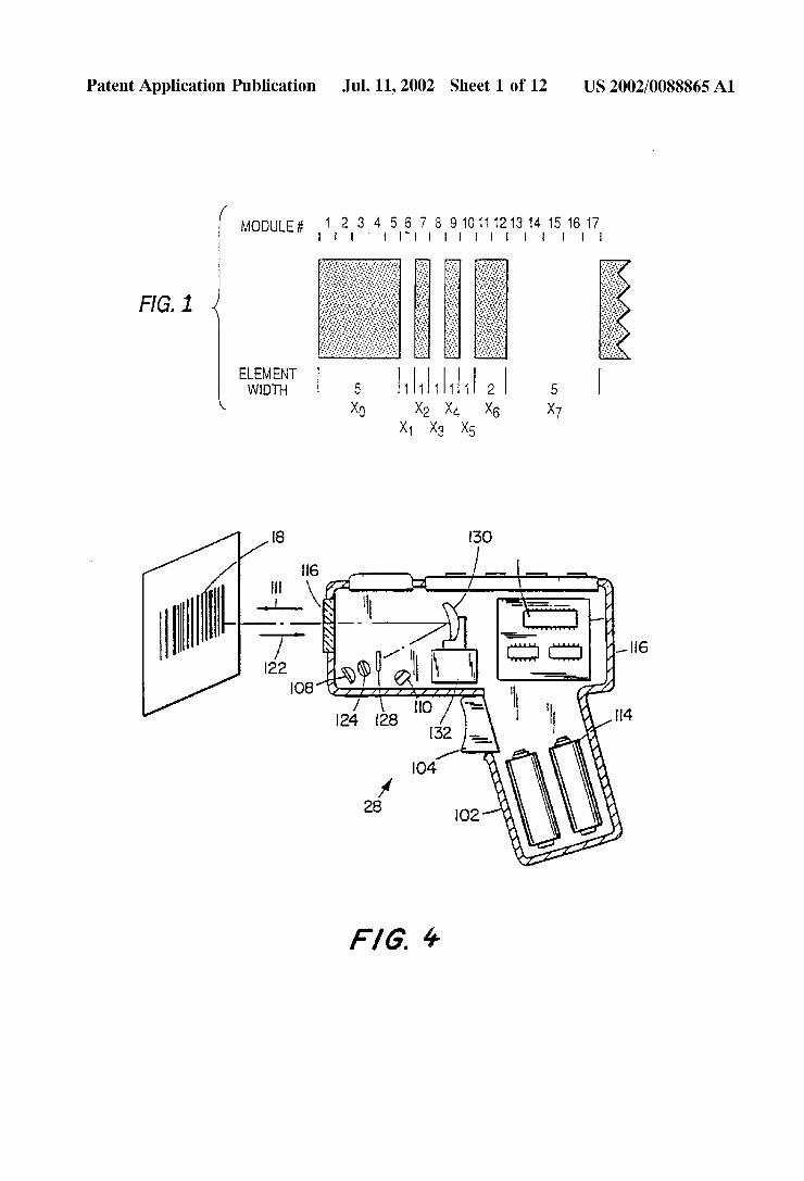
[0025] FIG. 1 is a diagram illustrating one example of a codeWord in PDF417;
[0026] FIG. 2 is a diagram illustrating the overall struc ture of a PDF417 symbol;
[0027] FIG. 3 is a table listing the number of error correction codeWords for a given security level in PDF417;
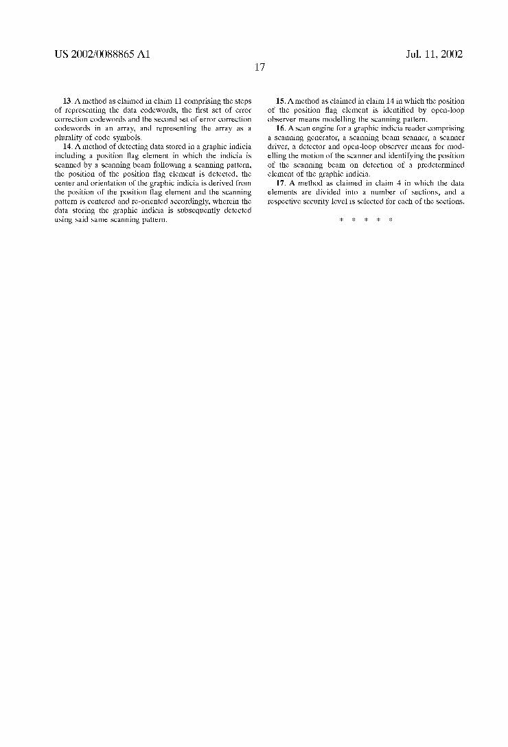
[0028] FIG. 4 illustrates a bar code reader implemented as a gun shaped device for reading the records of the present invention;
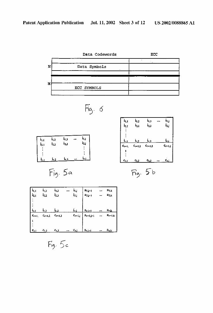
[0029] code; [0030] FIG. 5B shoWs an array of information cells and correction cells in a code;
FIG. 5A shoWs an array of information cells in a

US 2002/0088865 A1
[0031] FIG. 5C shows an array of information, correction and additional information cells;
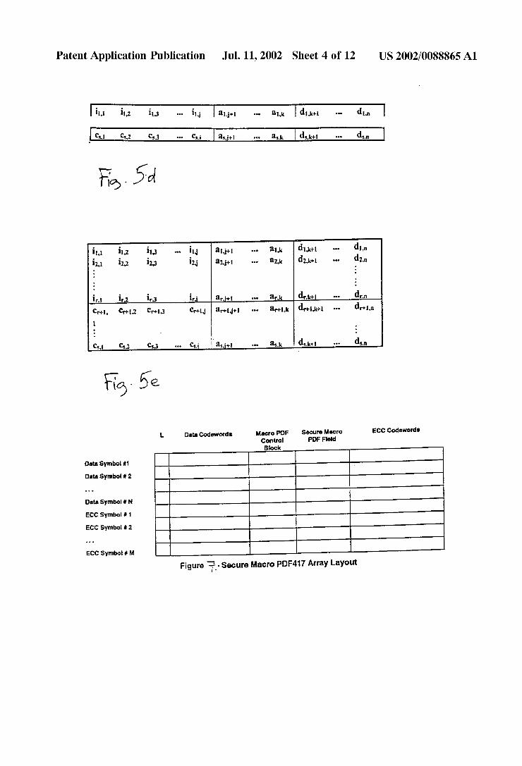
[0032] FIG. 5D shows an array of information, correction, additional information and projection cells in a code;
[0033] FIG. 5E shows the array of FIGS. 5A-D in the form of a two-dimensional symbol;
[0034] [0035] FIG. 7 shows a “secure macro” array layout;
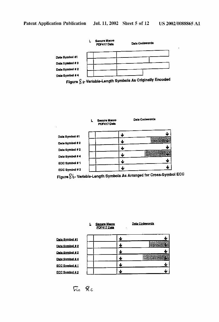
[0036] FIG. 8A shows a “secure macro” array including variable length symbols;
[0037] FIG. 8B shows a variation of FIG. 8A;
FIG. 6 shows one type of error correction scheme;
[0038] FIG. 8C shows a variation of FIG. 8B;
[0039] FIG. 8D shows a variable length symbol set as printed;
[0040] [0041] FIG. 10 shows an omni-directional one-dimen sional scanning pattern;
[0042] FIG. 11 shows a block diagram of a locator system;
[0043] FIG. 12 is a diagram representing digital ?lter implementation of smoothing ?lter open loop observer sys tems;
[0044] FIG. 13 is a diagram representing digital ?lter implementation of taut band element open loop observer system;
FIG. 9 shows a revised code symbol format;
[0045] FIG. 14 shows the orientation of a start and stop line along the start and stop patterns of a two-dimensional bar code symbol;
[0046] FIG. 15 shows the ?tting of a start and stop line to the coordinates of the detected start and stop patterns;
[0047] FIG. 16 is a ?owchart illustrating a data encoding process; and
[0048] FIG. 17 is a ?owchart illustrating a further data encoding process.
DESCRIPTION OF THE PREFERRED EMBODIMENTS
[0049] Reference will now be made in detail to presently preferred embodiments of the invention, eXamples of which are illustrated in the accompanying drawings.
Code PDF417
[0050] Before discussing the method and apparatus for encoding and decoding data in machine readable graphic form, such as the two-dimensional bar code PDF417, it is important to understand the structure of the two-dimensional bar code symbol itself.
[0051] Each PDF417 symbol is composed of a stack of rows of bar-coded information. Each row in the symbol consists of a start pattern, several symbol characters called “codewords”, and a stop pattern. A codeword is the basic unit for encoding a value representing, or associated with, certain numbers, letters, or other symbols. Collectively, the codewords in each row form data columns.
Jul. 11, 2002
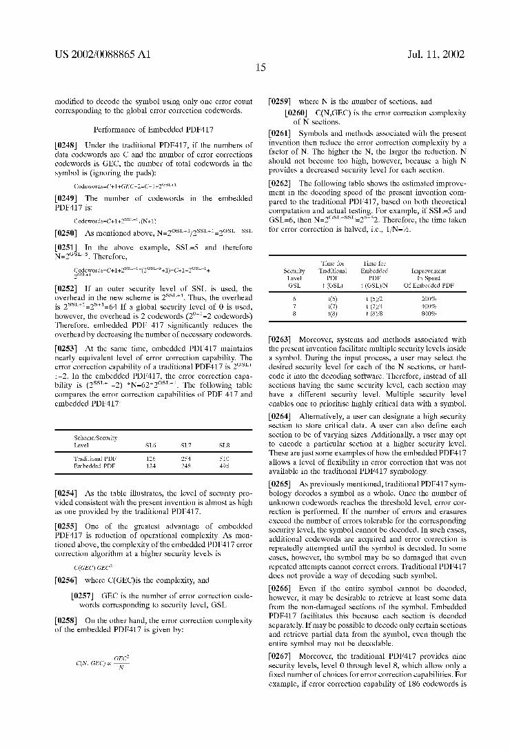
[0052] Both the number of rows and the number of data columns of the PDF417 symbol are variable. The symbol must have at least three rows and may have up to ninety rows. Likewise, within each row, the number of codewords or data columns can vary from three to thirty. Each PDF417 codeword consists of seventeen modules or units. There are four bars and four spaces in each codeword. Individual bars or spaces can vary in width from one to siX modules, but the combined total per codeword can be de?ned by an eight digit sequence, which represents the four sets of alternating bar and space widths within the codeword. This is called the “X-sequence” of the codeword and may be represented by the sequence X0, X1, . . . X7. For eXample, for an X-sequence of “51111125”, the ?rst element is ?ve modules wide, followed by ?ve elements one module wide, one element two modules wide, and the last element ?ve modules wide. This eXample is illustrated in FIG. 1.
[0053] The set of possible codewords is further partitioned into three mutually exclusive subsets called “clusters”. In the PDF417 symbol, each row uses only one of the three clusters to encode data, and each cluster repeats sequentially every third row. Because any two adjacent rows use different clusters, the decoder is able to discriminate between code words from different rows within the same scan line.
[0054] The cluster number of a codeword may be deter mined from its X-sequence using the following formula:
cluster number=X0—X2+X4—X6) mod 9
[0055] where “mod 9” is the remainder after division by nine. Referring to the codeword in FIG. 1, the cluster number is calculated as follows:
cluster number=5—1+1—2) mod 9=3
[0056] To minimiZe error probabilities, PDF417 uses only three clusters, even though nine are mathematically possible. Thus, each row uses only one of the three clusters 0, 3, or 6, to encode data, with the same cluster repeating sequen tially every third row. Row 0 codewords, for example, use cluster 0, row 1 uses cluster 3, and row 2 uses cluster 6, etc. In general, the cluster number may be determined from the row number as follows:
cluster number=((row number) mod 3)*3
[0057] There are 929 codeword values de?ned in PDF417. These values are 0 through 928. Each cluster presents the 929 available values with distinct bar-space patterns so that one cluster cannot be confused with another.
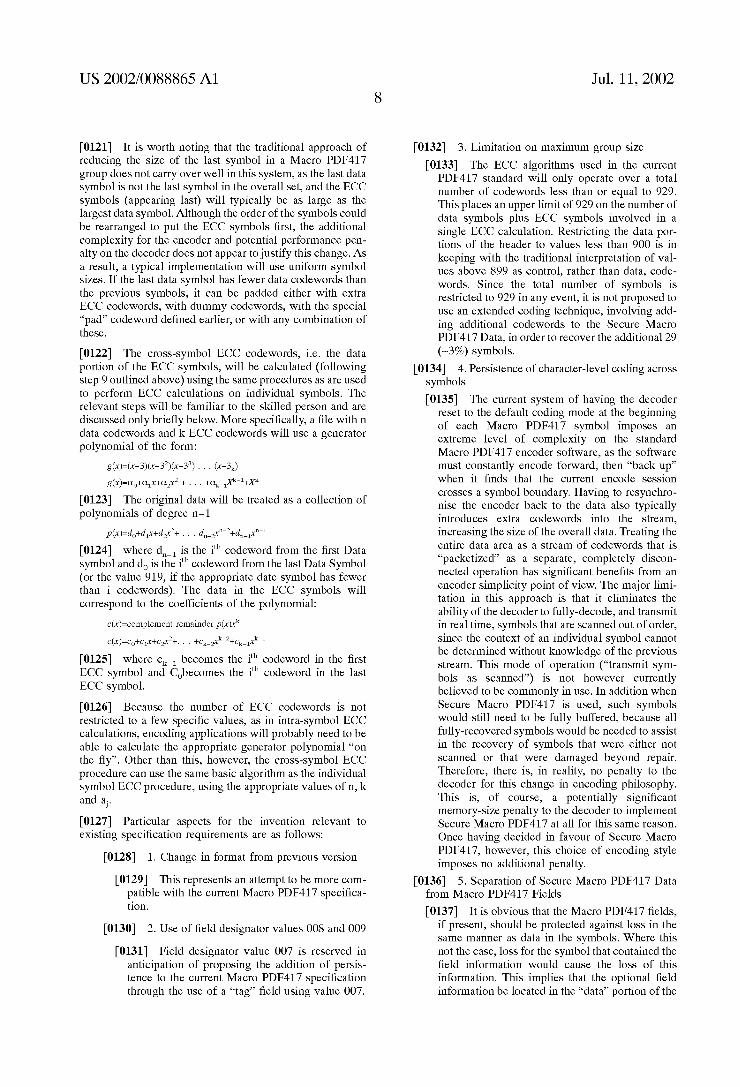
[0058] FIG. 2 is a block diagram showing the overall structure of a PDF417 symbol. Each row of the symbol consists of a start pattern, a left row indicator codeword L1, data codewords d1, or error detection/correction codewords Ci, a right new indicator codeword R1, and a stop pattern. The minimum number of codewords in a row is three, including the left row indicator codeword, at least one data codeword, and the right row indicator codeword. The right and left row indicator codewords, which are discussed further below, help synchroniZe the structure of the symbol.
[0059] The start and stop patterns identify where each row of the symbol begins and ends. PDF417 uses unique start and stop patterns. The start pattern, or left side of each row, has the unique pattern, or X-sequence, of “81111113”. The stop pattern, or right side of each row, has the unique X-sequence of “711311121”.

US 2002/0088865 A1
[0060] Every symbol contains one codeword (the ?rst data codeword in roW 0) indicating the total number of code Words Within the symbol, and at least tWo error-detection codeWords CO and C1. These tWo error-detection codeWords together form a checksum Which is tWo codeWords long.
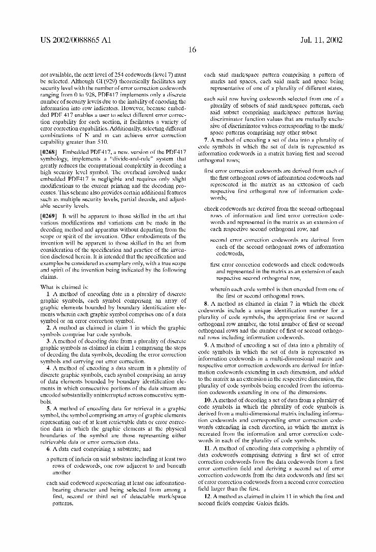
[0061] A PDF417 symbol can also encode data With error correction capability. The level of error correction capabil ity, called the “security level”, is selected by the user and ranges from 0 to 8. This means, for example, that at level 6, a total of 126 codeWords can be either missing or destroyed and the entire symbol can be read and decoded. FIG. 3 is a table shoWing the relationship betWeen the security level of the PDF417 symbol and the number of error correction codeWords Ci.
[0062] In addition to correcting for missing or destroyed data (knoWn as “erasures”), PDF417 can also recover from misdecodes of codeWords. Since it requires tWo codeWords to recover from a misdecode, one to detect the error and one to correct it, a given security level can support half the number of misdecodes that it can of undecoded codeWords.
[0063] This error correction feature is particularly useful When information in PDF417 format overlays partially erased coded Words. This partial erasure creates the possi bility that the unerased code portions Will distort portions of the encoded information. If that happens, errors can be corrected With the PDF417 tWo-dimensional bar code.
[0064] The roW indicator codeWords in a PDF417 symbol contain several key components: roW number, number of roWs, number of data columns, and security level. Not every roW indicator contains every component, hoWever. The information is spread over several roWs, and the pattern repeats itself every three roWs. The pattern for encoding the information in the roW indicator can be illustrated as fol loWs:
ROW 0: LD (roW #, # of roWs) RoW 1: L1 (roW #, security level) RoW 2: L2 (roW #, # of columns) RoW 3: L3 etc (roW #, # of roWs)
RU (roW #, # of columns) R1 (roW #, # of roWs) R2 (roW #, security level) R3 (roW #, # of columns)
[0065] In other Words, the left roW indicator codeWord Lo for the ?rst roW 0 contains the roW number (0) and the total number of roWs in the symbol. The right roW indicator codeWord R0 for roW 0 contains the roW number (0) and the number of data columns in the symbol, and so on.
[0066] Encoding data into a PDF417 symbol is typically a tWo-step process. First, data is converted into codeWord values of 0 to 928, Which represent the data. This is knoWn as “high-level encoding”. The values are then physically represented by particular bar-space patterns, Which is knoWn as “loW-level encoding”.
[0067] Encoders and decoders are discussed more com pletely in applications U.S. Ser. No. 07/851,505 and incor porated by reference herein.
[0068] The system is particularly relevant to bar code readers such as those disclosed and described in US. patent application Ser. Nos. 317,433 and 317,533, and incorporated herein by reference. The readers disclosed in the above patent applications are open system devices designed to read
Jul. 11, 2002
an optically encoded tWo-dimensional bar code and to convert the light re?ected from the pattern into electrical signals representative of the graphic indicia.
[0069] Referring to FIG. 4, a typical exemplary embodi ment of a bar code reader of converting means 28 is implemented as a gun shaped device 100, having a pistol grip type of handle 102. A movable manually actuated trigger sWitch 104 is employed to alloW the user to activate the light beam 117 and detector circuitry, typically after the time When the user has positioned the device to point at the symbol to be read. A light-Weight plastic housing 106 contains a laser light source 108, the detector 110, the optics and signal processing circuitry and the CPU 112, as Well as a poWer source or battery 114. A light-transmissive WindoW 116 in the front end of the housing 118 alloWs the outgoing light beam 120 to exit and the incoming re?ected light 122 to enter. The reader 100 is designed to be aimed at a bar code symbol by the user from a position in Which the reader 100 is spaced from the symbol, i.e., not touching the symbol or moving across the symbol. Typically, this type of hand-held bar code reader is speci?ed to operate in the range of perhaps several inches or even further.
[0070] The reader 100 may also function as a portable computer terminal, and in such embodiments include a keyboard and a display, such as described in the previously noted US. Pat. No. 4,409,470.
[0071] As further depicted in FIG. 4, a suitable lens 124 (or multiple lens system) may be used to focus the scanned beam into a scanning spot at an appropriate reference plane. Light source 108 such as a semiconductor laser diode is positioned to introduce a light beam into the axis of the lens 124, and the beam passes through a partially-silvered mirror 128 and other lenses or beam-shaping structure as needed. The beam is re?ected from an oscillating mirror 130 Which is coupled to a scanning motor 132 Which is energiZed When the trigger 104 is pulled. If the light produced by the source 146 is marginally visible, an aiming light may be included in the optical system. The aiming light if needed, produces a visible-light spot Which may be ?xed, or scanned just like the laser beam; the user employs this visible light to aim the reader unit at the symbol before pulling the trigger.
[0072] The system maximiZes the use of available space for encrypting data. The density of the encoded data is such that for a tWo-dimensional bar code symbol, a minimum of about 1600 characters can be encoded into a space of approximately 5“><1/z. In addition to being compact, the system provides for high security in the transmission of information.
[0073] A loW-level decoder may be embodied in a com puter program operating on a microcomputer separate from the host computer. The loW-level decoder Would be prefer ably connected to the host computer by a standard interface, such as an RS-232 interface, for transmitting the codeWord values after they are decoded. Alternatively, the loW-level decoder could be embodied entirely in hardWare, or a combination of a hardWare and softWare, Which is physically located in either the scanner itself or the host computer.
[0074] The matrix of codeWord values from loW-level decoder is decoded into usable data by a high-level decoder, Which may be embodied as a separate computer program operating on the host computer. For example, PDF417 has

US 2002/0088865 A1
three prede?ned modes and nine reserved modes. The pre de?ned modes are Binary, EXC, and Numeric. In the Binary mode, each codeWord can encode 1.2 bytes. In the EXC mode, the alphanumeric data can be encoded in double density (i.e., tWo characters per code Word), and in Numeric mode, the numeric data can be packed in almost triple density. Therefore, the high-level decoder in the host com puter Will further decode the codeWord values (0-928) from the loW-level decoder, depending on the mode, to obtain the actual data embodied in the symbol. The decoded data from the high-level decoder may then be used by a user applica tion program also operating on the host computer 112.
[0075] According to an aspect of the invention it is desired to enhance the information carrying capability by using “macro-PDF” technology according to Which the informa tion is stored in a plurality of symbols rather than in an individual symbol. The information can then be vieWed as a datastream continuing across symbols. Macro-PDF alloWs large documents to be encoded into multiple PDF-417 symbols. But if any one of these symbols is lost it may be impossible to recreate the document, and this cannot be remedied simply by adding more error correction codeWords into each of the individual PDF symbols.
[0076] Referring to the arrays in FIGS. 5a to 56, the invention is described in more detail.
[0077] Referring ?rstly to FIG. 5a, the array is made up of a plurality of cells arranged in tWo dimensions and having R roWs and J columns. Each cell is referenced iL1 . . . inj. Each cell represents a codeWord comprising a value betWeen Zero and a predetermined integer number and is represented by a predetermined pattern in a symbology. The information cells (i-cells) thus represent the information encoded. If the number of i-cells is not suf?cient to ?ll the array, the empty cells are ?lled With a predetermined value, for example and preferably Zero.
[0078] Referring noW to FIG. 5b error control or correc tion cells, c-cells, are calculated using an appropriate error control mechanism and arranged in columns beloW the i-cells in a column-Wise calculation. Accordingly, for the ?rst column, the values of the c-cells are calculated Wherein the values of the i-cells in the same column. The process is repeated for each column. The c-cells are arranged in additional roWs number r+1 to s.
[0079] As shoWn in FIG. 5c, a-cells are added in addi tional columns referenced j+1 to k. The a-cells record various information, in particular a unique ?le identi?cation number representing a sequence number of the macro-2-d code, the current roW number, the total number of roWs (s) and the number of information roWs It Will be appreci ated that the only information that Will change betWeen roWs is the roW number, the other information Will be identical for all roWs of the same matrix. A further set of columns referenced k+1 to n are added incorporating d-cells. The d-cells are calculated using an error-control algorithm, one roW at a time. The d-cells protect the i-cells (or c-cells) and a-cells in the same roW. Each of these roWs is recorded as an individual 2D symbol and the collection of 2D symbols form the macro 2D symbol Which is shoWn in the s><n array of FIG. 56. For decoding, the encoding procedure is reversed. Each symbol (corresponding to one roW) is decoded ?rst, correcting errors and ?lling erasures. The decoded i-cells and c-cells are put in a matrix similar to that shoWn in FIG.
Jul. 11, 2002
17b. If some of the roWs are missing, or more unlikely decoded in error, the error control code in the columns is used to correct them. Thus the data is fully recovered even When some individual symbols of the macro-symbol are lost.
[0080] Yet further improvements are shoWn in relation to FIG. 6. The basic approach involves the use of M error correcting symbols Which can alloW up to M macro PDF symbols to be lost. The advantage of this scheme is that it alloWs the use of the current encoding techniques available for PDF417 and does not require the de?nition of a neW Galois ?eld (of the type Well knoWn in PDF technology and relating to the number of codeWord values available).
[0081] The disadvantage of this scheme is that it is very time intensive. Let us assume that We have a total of M+N symbols and each symbol has about 200 codeWords at security level (slev) 5 (62x2 error correcting and detecting codeWords). The total number of data codeWords Will be N* (200-64) and the total overhead Will be M*200+N* 64 (total codeWords=(M+N) 200). Even if one of the symbols is lost the number of extra error correction attempts that have to be made to reconstruct the Macro PDF message Will be 200 62+M (200-62 along the columns and M along the roWs). The total extra time required for this effort Will be (138+M) T (slev 5). Assuming Security level 5 error correction time to be 500 ms and the total alloWable symbols to be lost to be (M=5, also N assumed to be about 20) the total time for this effort Will be 143.5 sec or 71.5 seconds.
[0082] In the neW proposed scheme according to another aspect of the invention a different and larger Galois ?eld is proposed. For example, let us assume that We choose a Galois ?eld GF(8192). The data symbols are ?rst encoded and printed as normal PDF symbols (N symbols using Galois Field GF (929) at security level 5). Then all the codeWords (data and error correction) are encoded using GF(8192) (The error correcting codeWords Will have values ranging from 0 to 8191). If We alloW up to 5 symbols to be lost this implies that We should have an error correction capability of about 1000. Since each character can have 4 digits the total number of numeric characters Will be 4000. As We have a packing ef?ciency (characters per codeWord) say of 2.93 this implies that the number of codeWords required Will be about 1333. AlloWing (200-64) codeWords per symbol this implies that the number of symbols required Would be 1333/146~9. Each of these symbols is also encoded at security level 5.
[0083] The total overhead noW Will be 9*200+20*64 as opposed to 5 *200+20*64. But the total number of erasures to be corrected Will be only about 1333 Which has the time complexity of about 4 times the time complexity of a security level 8 symbol. As the time complexity of a security level 8 symbol (on the same scale as the 500 ms time for slev 5) is about a second, the total decode time Will be about 4*1+9*.5 (9 sec level 5 decodes) ~8.5 seconds plus some additional high level decode time to convert codeWords back to the Galois ?eld GF (8192). This scheme can be repeatedly applied on sets of 20 symbols.
[0084] The basic scheme alloWs the advantages of the same Galois Field—no neW primitive poWer tables are required—and less space; an overhead for above example 2280 codeWords. On the other hand it has the disadvantages of a long time to decode in, for example 71.5 seconds.
US 2002/0088865 A1
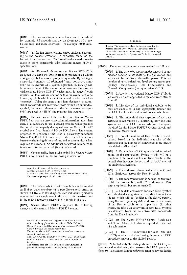
[0085] The proposed improvement has a time to decode of for example 8.5 seconds and the disadvantages of a neW Galois ?eld and more overhead—for example 3080 code Words.
[0086] Yet further improvements can be envisaged accord ing to the present invention, in particular rendering the format of the “secure macro” information discussed above to make it more compatible With existing macro PDF417 speci?cations.
[0087] As discussed above secure Macro PDF417 is designed to extend the error correction process used Within a single symbol across a group of symbols. By adding a user-de?ned number of additional “error correction sym bols” to the overall set of symbols printed, the neW system becomes tolerant of the loss of entire symbols. Because, as With standard Macro PDF417, each symbol is “tagged” With information to alloW its location Within the overall set to be knoWn, symbols Which are not recovered can be treated as “erasures”. Using the same algorithms designed to recon struct codeWords not recovered from Within an individual symbol, the extra codeWords in the “error correction sym bols” are used to “?ll in” the missing data symbols.
[0088] Because some of the symbols in a Secure Macro PDF417 set contain error correction information rather than data, it is necessary to use a coding scheme Which permits the decoder to uniquely distinguish Secure Macro PDF417 symbol sets from Standard Macro PD417 sets. The system proposed to guarantee this uses a previously-unde?ned Macro PDF417 ?eld to indicate that the data in this set has been encoded using this technique, and to communicate data required to decode it. An additional codeWord, number 920, is reserved for use as a pad (?ller) codeWord.
[0089] Conceptually, then, each symbol in a Secure Macro PDF417 set consists of the folloWing information:
A portion of the overall data being encoded A standard Macro PDF417 control block A Macro PDF417 ?eld containing Secure Macro PDF417 data The standard per-symbol ECC data.
[0090] The codeWords in a set of symbols can be treated as if they Were members of a tWo-dimensional array, as shoWn in FIG. 7. In this diagram, each individual symbol is represented by a single roW in the matrix. Successive roWs in the matrix represent successive symbols in the set.
[0091] Secure Macro PDF417 imposes the folloWing changes to the standard Macro PDF417 system:
Optional ?eld information is appended to the data stream, rather than being placed after the Macro PDF417 Control Block. The only ?eld that appears after the Macro PDF417 Control Block is the Secure Macro ?eld. The Secure Macro ?eld information is mandatory, and must appear in each symbol. The Macro PDF417 Terminator codeword (922) is no longer required at the end of the stream, but may optionally be included. The decoder does not reset its state to Text Compression (low-level coding) mode at the beginning of the second
Jul. 11, 2002
-continued
through N’th symbols. Rather, the internal state for the decoder persists across symbols. This means that the codewords in the data symbols may be treated as a single continuous stream that is “packetized” into the individual symbols.
[0092] The encoding process is summariZed as folloWs:
[0093] 1. The date to be represented is encoded in any manner deemed appropriate to the application and Which Will be familiar to the skilled person. This can involve either standard loW-level coding techniques (Binary Compression), Text Compression and Numeric Compression) or appropriate GLI’S.
[0094] 2. Any desired optional Macro PDF417 ?elds are calculated and appended to the codeWord stream from #1.
[0095] 3. The siZe of the individual symbols to be used are calculated in any appropriate manner and the ECC level for the individual codeWords chosen.
[0096] 4. The individual data capacity of the data symbols is determined by subtracting from the total symbol siZe the ECC codeWords and the space required for the Macro PDF417 Control Block and the Secure Macro ?eld.
[0097] 5. The total number of Data Symbols is cal culated based on the individual capacity of the symbols and the number of codeWords in the stream calculated in #1 and #2.
[0098] 6. The number of ECC symbols is determined based on the application. Typically, this Will be a function of the total number of Data Symbols, the overall data integrity desired and the ECC level of the individual symbols.
[0099] 7. The codeWord stream calculated in #1 and #2 is distributed across the Data Symbols.
[0100] 8. The codeWord stream is padded, as required to ?ll the last symbol, With 920 codeWords. (This step is optional, but recommended)
[0101] 9. The data codeWords for each ECC Symbol are calculated using standard Reed-Solomon tech niques Which Will be familiar to the skilled person, using the corresponding data codeWords from each of the Data symbols as the input data. (In other Words, the ?fth data codeWord in each ECC Symbol is calculated from the collective ?fth codeWords from the Data Symbols)
[0102] 10. The Macro PDF417 Control Block data and Secure Macro ?eld data is appended to the end of each symbol.
[0103] 11. The ECC codeWords for each Data and ECC Symbol are calculated using the standard ECC procedure knoWn to the skilled person.
[0104] Note that only the data portions of the ECC sym bols are calculated using the cross-symbol ECC procedure (step 9). The symbol length codeWord (?rst codeWord in the

US 2002/0088865 A1
symbol), Macro PDF417 control block and Secure Macro ?eld are generated using normal (non-ECC) procedure (step 10), and the ECC codewords in the ECC symbols are generated using the same intra-symbol ECC procedures as for the data symbols (step 11).
[0105] This encoding system eliminates the restriction that the decoder reinitialiZe to the Text Compression (loW level coding) Mode at the beginning of each neW symbol. This greatly simpli?es the encoding process, as it permits the encoder to process the entire input set in the most ef?cient manner possible, Without having to concern itself With the effects of Symbol boundaries.
[0106] When decoding the data, the decoder is to treat the entire data codeWord set as a continuous stream, also With out regard for symbol boundaries. This implies that the encoder is free, should it so desire, to “break up” codeWord sequences normally considered indivisible (e.g. GLI invo cations, groups of 5 Binary-Compression-Mode-encoded codeWords, etc.) across symbol boundaries.
[0107] If the application desires to include any of the Macro PDF417 optional ?elds, this information may be appended to the end of the data stream. Each such ?eld is encoded as standard (see the AIM speci?cation) (923+Field ID +value). Note that the data in the Secure Macro ?eld largely eliminates the need for the “Segment Count” optional ?eld.
[0108] For applications in Which the total number of symbols (data +ECC) does not exceed 900, the Secure Macro PDF417 ?eld has the folloWing format:
[0109] CodeWord
Index Values Meaning
0 923 Field tag 1 008 Field designator — Secure Macro
PDF417 2 1-899 Number of data symbols in this set
(“DCOUNT”) 3 1-899 Number of ECC symbols in this set
(“ECOUNT”)
[0110] The position of a symbol Within a set is determined by the Segment Index portion of the Control Block. The data symbols Will have Segment Index values ranging from 0 through DCOUNT-1, inclusive. ECC symbols Will have Segment Index values betWeen DCOUNT and DCOUNT +ECOUNT-1, inclusive.
[0111] For applications in Which the total number of symbols (data+ECC) is greater than 900, the data must be broken up into Secure Macro PDF417 groups. Each Secure Macro PDF417 group must have a total number of symbols (Data+ECC) less than or equal to 900. There may be up to 900 such groups in a ?le, hoWever the total number of symbols in the entire set may not exceed 99,999.
[0112] In this situation, the Secure Macro PDF417 ?eld has the folloWing format:
Jul. 11, 2002
[0113] CodeWord
Index Values Meaning
0 923 Field tag 1 008 Field designator — Secure Macro
PDF417, Long form 2 1-899 Total number of groups minus one
(total number of groups is one more than the value of this
codeword) 3 0-899 Index number of this group 4 1-899 Number of data symbols in this group
(“DCOUNT”) 5 1-899 Number of ECC symbols in this group
(“ECOUNT”) 6-7 Segment Index value of the
?rst symbol in this group
[0114] The ECC symbols in each group correct the data symbols in that same group.
[0115] The position of a symbol Within a set is again determined by the Segment Index portion for the Control Block. The data symbols in a group Will have Segment Index values ranging from FIRSTSYM through FIRSTSYM+ DCOUNT-1, inclusive. ECC symbols Will have Segment Index values betWeen FIRSTSYM+DCOUNT and FIRSTSYM+DCOUNT+ECOUNT—1, inclusive.
[0116] Under normal circumstances, each of the symbols in a Secure Macro PDF417 set Will have the same number
of data and ECC codeWords. There is no reason, hoWever, Why an application could not choose different values for different symbols, subject to the folloWing mandatory restriction: The number of data codeWords in each of the ECC Symbols must be at least as large as the maximum number of data codeWords in any of the Data Symbols. This restriction is necessary to ensure that the cross-symbol ECC calculations can be carried out properly (step 9 above). In applications Where some Data Symbols do have feWer data codeWords than others, the “missing” data codeWords Will be treated as being a special pad value (920) for purposes of the cross-symbol ECC calculations.
[0117] FIGS. 8a and 8b shoW a hypothetical set of four data symbols and tWo ECC symbols. The second and fourth data symbols have a smaller number of codeWords than the ?rst and third.
[0118] FIG. 8c shoWs the same set after the cross-symbol ECC calculations. The shaded portions of the second and fourth symbol indicate the area padded With 920 codeWords for the purposes of the ECC calculation.
[0119] printed.
[0120] Although the number of data codeWords in an ECC symbol must meet the restriction mentioned above, there is no corresponding restriction on the number of ECC code Words in any symbol in the set. In a typical application, the entire Secure Macro PDF417 set Will be encoded at a ?xed ECC level. There is no reason, hoWever, that prevents ECC symbols or data symbols from using varying ECC levels. The ECC level of an individual symbol is indicated in the roW indicator codeWords as With standard Macro PDF417 and non-macro PDF417.
FIG. 8a' shoWs the ?nal symbol set as it might be