error-proofing techniques (poka-yoke) concept · eprefer.ppt - 09 2/13/00 error-proofing techniques...
TRANSCRIPT
EPREFER.PPT - 012/13/00
ERROR-PROOFING TECHNIQUES(Poka-Yoke) CONCEPT
SENSOR INFORMATION:BASIC TYPES OF SENSORS• Discrete sensors• Analog sensors
TYPES OF PRESENCE SENSORS• Physical contact• No physical contact
TYPES OF NON-CONTACT SENSORS• Reed relays• Inductive• Capacitive• Photoelectric sensors
ADVANTAGES OF THE VARIOUS TYPES• Functionality• Costs• Areas of application
EPREFER.PPT - 022/13/00
ERROR-PROOFING TECHNIQUES(Poka-Yoke) CONCEPT
BASIC TYPES OF SENSORS:ANALOG SENSORS• Answer the question: “Where is the part?”
or• “To what level have we filled the container?”
DISCRETE SENSORS• The part is present or is not present.• Most frequently asked question in a manufacturing
operation.
EPREFER.PPT - 032/13/00
ERROR-PROOFING TECHNIQUES(Poka-Yoke) CONCEPT
TYPES OF PRESENCE SENSORS:PHYSICAL CONTACT• e.g. Limit switches• Advantages - Can carry more current
- Gap between terminals
NO PHYSICAL CONTACT• Advantages - No physical contact
- Better for counting sensitive surfaces,e.g. painted or polished surfaces
- No moving parts- Faster
EPREFER.PPT - 042/13/00
ERROR-PROOFING TECHNIQUES(Poka-Yoke) CONCEPT
TYPES OF NON-CONTACT SENSORS:REED RELAYS• Target is magnetic• Will not respond to non-magnetic targets
with reliability.
INDUCTIVE• Based on metal targets; will not respond
to non-metallic targets with high reliability.
CAPACITIVE• Cannot distinguish between the real target
and something else in the target region. Must control what comes close to the target.
PHOTOELECTRIC• Can be fooled by a non-target.
EPREFER.PPT - 052/13/00
ERROR-PROOFING TECHNIQUES(Poka-Yoke) CONCEPT
TYPES OF NON-CONTACT SENSORS:REED RELAYSTypical range: Up to 1.5 in. (approx. 4 cm)• Two hermetically sealed metal foil reeds which make contact
with each other to close the circuit, when in the vicinity of amagnet (permanent or electro-magnet).
• The differential is determined by differencing the point of firstcontact from the point of last contact.
• Magnet approach must be in a direction parallel to the directionof the line connecting the tow reeds.
Best applications for magnetically actuated switches in general:• Security and safety
• to avoid false tripping• security door interlock for heavy machinery; end of travel
for elevators, cranes, and the like.• Sensing through walls (non-ferrous, e.g. Aluminum and
Magnesium).• Pallet identification in synchronous automated assembly lines.• Relative dirty environments (e.g. dust, dirt, sand, oil, or coolant
fluids).• Whenever high response speeds are required.
Disadvantages - poor long-term reliability (moving parts)
EPREFER.PPT - 062/13/00
ERROR-PROOFING TECHNIQUES(Poka-Yoke) CONCEPT
TYPES OF NON-CONTACT SENSORS:INDUCTIVE SENSORS• Principle of Operation:
• Eddy currents are induced in the target (metallic)by the electromagnetic.
• The target reacts with the Eddy currents as afunction of the distance from the field.
• Inside the field, the target attenuates the magnitudeof the Eddy currents.
• Outside the field, the target does not impede theEddy currents.
• This type of oscillator is referred to as a ECKO(Eddy Current Killed Oscillator).
EPREFER.PPT - 072/13/00
ERROR-PROOFING TECHNIQUES(Poka-Yoke) CONCEPT
TYPES OF NON-CONTACT SENSORS:CAPACITIVE SENSORS• Principle of Operation:
• Senses all materials• Contain a high frequency oscillator with one of its
capacitor plates built into the sensor.
• Method of Application:• All materials are sensed through a change on the
dielectric characteristics.• Ideal applications include bulk materials and liquids
in containers of glass and plastic.
• Characteristics:• Poor choice for metal targets.• Is very sensitive to environmental factors.• Sensing range depends greatly on the material being
sensed.• Can be misled and therefore it is important to control
the material which is presented to the sensor.
EPREFER.PPT - 082/13/00
ERROR-PROOFING TECHNIQUES(Poka-Yoke) CONCEPT
TYPES OF NON-CONTACT SENSORS:PHOTOELECTRIC SENSORSPhotoelectric controls need no physical contact and are ideal where sensedobjects must remain untouched. Photoelectric controls respond rapidly toparts moving quickly and in varying positions along a conveyor, yet operatedependably if actuated only infrequently. There are controls for indoor oroutdoor use, for varying ambient light conditions, for high vibration, for areasrestrictive in space, and even for explosive locations.
Typical applications include:• Counting• Labeling• Conveyor control• Bin level control• Parts inspection• Feed and/or fill control• Package handling• Thread break detection
• Edge guide• Web break detection• Regristration control• Food processing• Parts monitoring and sorting• Batch counting• Robotics• Parts handling
EPREFER.PPT - 092/13/00
ERROR-PROOFING TECHNIQUES(Poka-Yoke) CONCEPT
TYPES OF NON-CONTACT SENSORS:PHOTOELECTRIC SENSORSConveyor ControlThis application involves sorting brown cardboard boxes which are coded with up to four black marks per box. The application is to sense the number of marks on each box.
Package HandlingA diffuse scan photoelectric control is used to detect the light reflected from the object in this application. The control detects the light reflected off the box, turning ON and OFF the gluing machine.
LabelingThis application is designed to detect the leading edge of a black bar code on a read and write label. The labels are edge to edge on a spool. When the bar code is detected the sensor output triggers a laser bar code reader which reads the bar code.
Food ProcessingThis application monitors the level of an accumulator in a meat processing facility. A photoelectric control detects a fill level of hot-dogs in the accumulator then turns on the conveyor for a preset time period. Side walls of the accumulator are polished stainless steel. The equipment is subject to daily washdown.
Fill Level ControlThis application inspects the fill level of various jars of food products. The photoelectric system produces an output when either an under or over fill condition is detected.
Parts HandlingFiber optics are ideal for areas too small for a standard photoelectric control. The fiber optic cables direct the light from the base to where the sensing is needed.
EPREFER.PPT - 0102/13/00
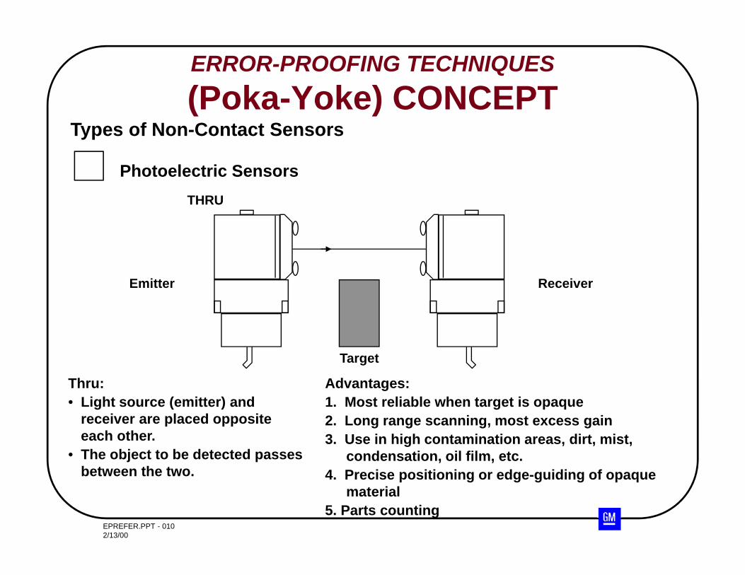
Target
Thru:• Light source (emitter) and
receiver are placed opposite each other.
• The object to be detected passes between the two.
Advantages:1. Most reliable when target is opaque2. Long range scanning, most excess gain3. Use in high contamination areas, dirt, mist,
condensation, oil film, etc.4. Precise positioning or edge-guiding of opaque
material5. Parts counting
Types of Non-Contact Sensors
Photoelectric Sensors
Emitter Receiver
THRU
ERROR-PROOFING TECHNIQUES(Poka-Yoke) CONCEPT
EPREFER.PPT - 0112/13/00
ERROR-PROOFING TECHNIQUES(Poka-Yoke) CONCEPT
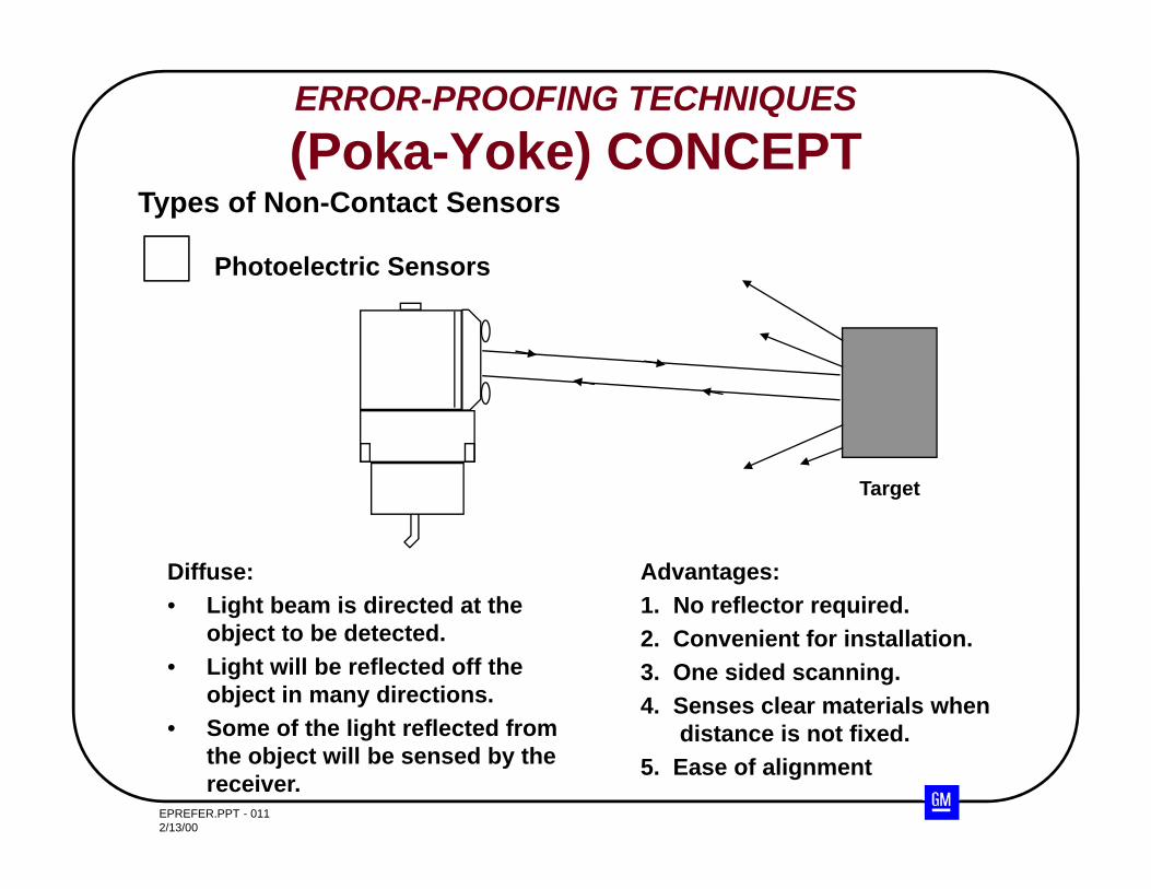
Diffuse:• Light beam is directed at the
object to be detected.• Light will be reflected off the
object in many directions.• Some of the light reflected from
the object will be sensed by the receiver.
Advantages:1. No reflector required.2. Convenient for installation.3. One sided scanning.4. Senses clear materials when
distance is not fixed.5. Ease of alignment
Types of Non-Contact Sensors
Photoelectric Sensors
Target
EPREFER.PPT - 0122/13/00
ERROR-PROOFING TECHNIQUES(Poka-Yoke) CONCEPT
TYPES OF NON-CONTACT SENSORS:PHOTOELECTRIC SENSORS
Proximity (diffuse) Background Suppression
Background suppression utilizes 2 receivers behind the receiving lens. They areaimed at a precise point in front of the unit and sense the presence of a targetwhen the output of both receives are equal.
Applications:
• Material handling - conveying systems• Collision detection for AGV’s (Automatic Guided Vehicles)• Car / truck wash• Level sensing
EPREFER.PPT - 0132/13/00
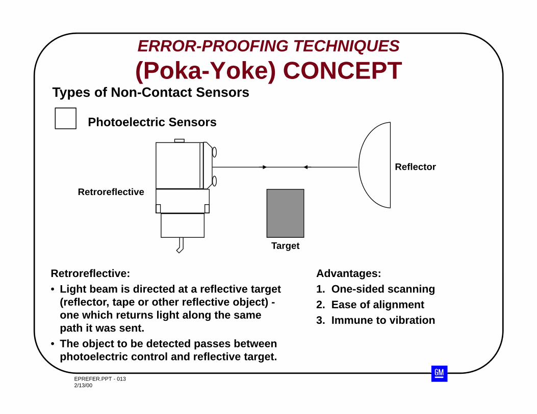
Retroreflective:• Light beam is directed at a reflective target
(reflector, tape or other reflective object) -one which returns light along the same path it was sent.
• The object to be detected passes between photoelectric control and reflective target.
Advantages:1. One-sided scanning2. Ease of alignment3. Immune to vibration
Types of Non-Contact Sensors
Photoelectric Sensors
Target
Retroreflective
Reflector
ERROR-PROOFING TECHNIQUES(Poka-Yoke) CONCEPT
EPREFER.PPT - 0142/13/00
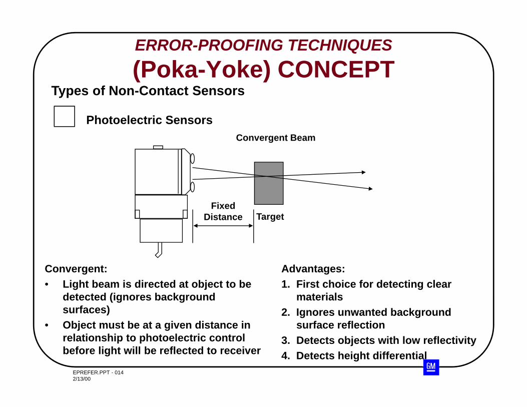
Convergent:• Light beam is directed at object to be
detected (ignores background surfaces)
• Object must be at a given distance in relationship to photoelectric control before light will be reflected to receiver
Advantages:1. First choice for detecting clear
materials2. Ignores unwanted background
surface reflection3. Detects objects with low reflectivity4. Detects height differential
Types of Non-Contact Sensors
Photoelectric Sensors
Target
Convergent Beam
FixedDistance
ERROR-PROOFING TECHNIQUES(Poka-Yoke) CONCEPT
EPREFER.PPT - 0152/13/00
ERROR-PROOFING TECHNIQUES(Poka-Yoke) CONCEPT
TYPES OF NON-CONTACT SENSORS:PHOTOELECTRIC SENSORSFiber Optic Sensors
What do you do when the physical constraints of the application don’t allow forinstalling regular, self-contained sensors? Maybe the target is in a high temperatureor chemically aggressive environment. Perhaps the target is small or very fast-moving.Fiber-optics, applied to photoelectric scanning, solves these problems.
Fiber Optics and SensingAll fiber optic sensing mode are implemented using one type of amplifier which containsboth emitter and receiver in one housing.
Fiber Optic Thru-beam ScanningUsing two opposed, individual fiber optic cables, the object to be detected breaks thebeam. The target must be at least the same dimension as the effective beam, which inthis case, is the bundle diameter. Because the beam is very small, the detection can bevery precise. A typical application might be edge detection for a web printing press.Needle tips reduce the beam dimension for use with extremely small targets, typical forapplication in semiconductors and pharmaceutical industries.
Typical application:• Small parts detection• Edge detection• High temperature environment (600 degrees F+)
EPREFER.PPT - 0162/13/00
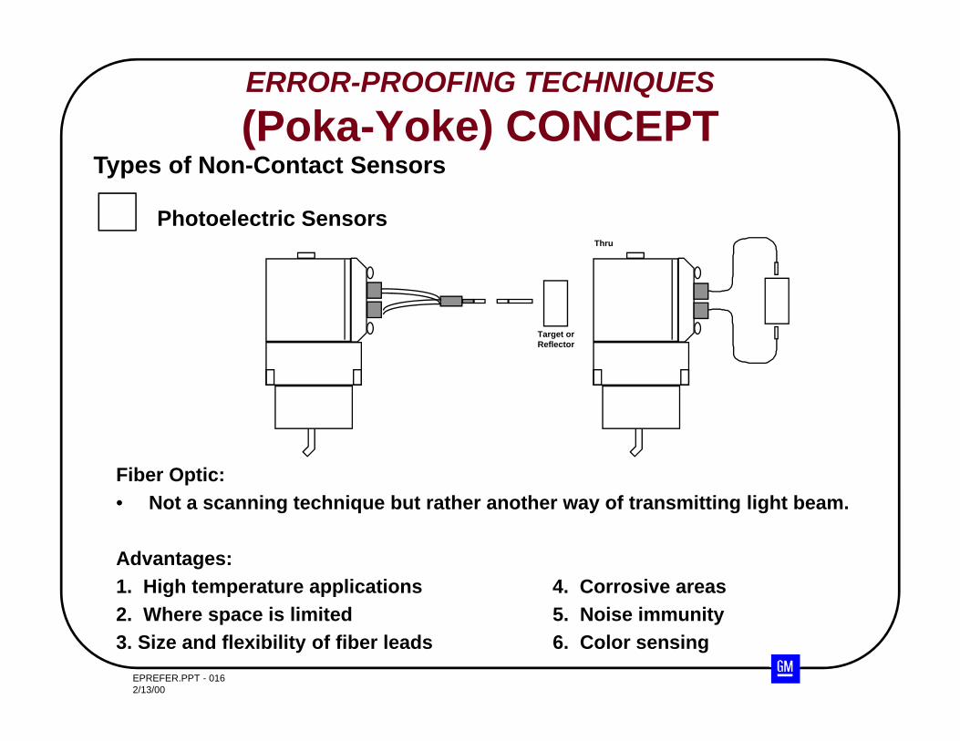
Fiber Optic:• Not a scanning technique but rather another way of transmitting light beam.
Advantages:1. High temperature applications 4. Corrosive areas2. Where space is limited 5. Noise immunity3. Size and flexibility of fiber leads 6. Color sensing
Types of Non-Contact Sensors
Photoelectric Sensors
Target orReflector
Thru
ERROR-PROOFING TECHNIQUES(Poka-Yoke) CONCEPT
EPREFER.PPT - 0172/13/00
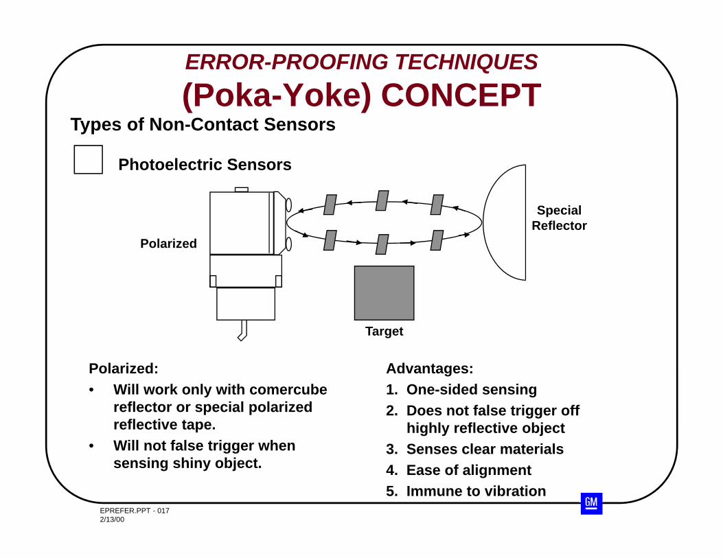
Polarized:• Will work only with comercube
reflector or special polarized reflective tape.
• Will not false trigger when sensing shiny object.
Advantages:1. One-sided sensing2. Does not false trigger off
highly reflective object3. Senses clear materials4. Ease of alignment5. Immune to vibration
Types of Non-Contact Sensors
Photoelectric Sensors
Target
Polarized
SpecialReflector
ERROR-PROOFING TECHNIQUES(Poka-Yoke) CONCEPT
EPREFER.PPT - 0182/13/00
ERROR-PROOFING TECHNIQUES(Poka-Yoke) CONCEPT
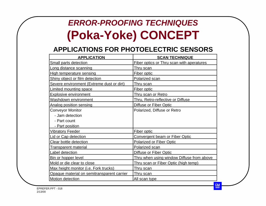
APPLICATION SCAN TECHNIQUESmall parts detection Fiber optics or Thru scan with aperaturesLong distance scanning Thru scanHigh temperature sensing Fiber opticShiny object or film detection Polarized scanSevere environment (Extreme dust or dirt) Thru scanLimited mounting space Fiber opticExplosive environment Thru scan or RetroWashdown environment Thru, Retro-reflective or DiffuseAnalog position sensing Diffuse or Fiber OpticConveyor Monitor - Jam detection - Part count - Part position
Polarized, Diffuse or Retro
Vibratory Feeder Fiber opticLid or Cap detection Convergent beam or Fiber OpticClear bottle detection Polarized or Fiber OpticTransparent material Polarized scanLabel detection Diffuse or Fiber OpticBin or hopper level Thru when using window Diffuse from aboveMold or die clear to close Thru scan or Fiber Optic (high temp)Max height monitor (i.e. Fork trucks) Thru scanOpaque material on semitransparent carrier Thru scanMotion detection All scan type
APPLICATIONS FOR PHOTOELECTRIC SENSORS
EPREFER.PPT - 0192/13/00
ERROR-PROOFING TECHNIQUES(Poka-Yoke) CONCEPT
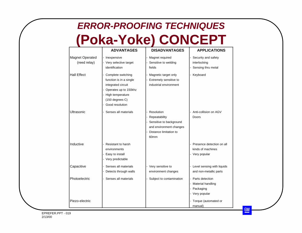
ADVANTAGES DISADVANTAGES APPLICATIONS
Magnet Operated - Inexpensive - Magnet required - Security and safety(reed relay) - Very selective target - Sensitive to welding interlocking
identification fields - Sensing thru metal
Hall Effect - Complete switching - Magnetic target only - Keyboard function is in a single - Extremely sensitive to integrated circuit industrial environment- Operates up to 150khz- High temperature (150 degrees C)- Good resolution
Ultrasonic - Senses all materials - Resolution - Anti-collision on AGV- Repeatability Doors- Sensitive to background and environment changes- Distance limitation to 60mm
Inductive - Resistant to harsh - Presence detection on all environments kinds of machines- Easy to install - Very popular- Very predictable
Capacitive - Senses all materials - Very sensitive to - Level sensing with liquids- Detects through walls environment changes and non-metallic parts
Photoelectric - Senses all materials - Subject to contamination - Parts detection- Material handling- Packaging- Very popular
Piezo-electric - Torque (automated or manual)
EPREFER.PPT - 0202/13/00
ERROR-PROOFING TECHNIQUES(Poka-Yoke) CONCEPT
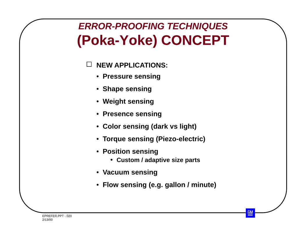
NEW APPLICATIONS:• Pressure sensing
• Shape sensing
• Weight sensing
• Presence sensing
• Color sensing (dark vs light)
• Torque sensing (Piezo-electric)
• Position sensing• Custom / adaptive size parts
• Vacuum sensing
• Flow sensing (e.g. gallon / minute)
EPREFER.PPT - 0212/13/00
ERROR-PROOFING TECHNIQUES(Poka-Yoke) CONCEPT
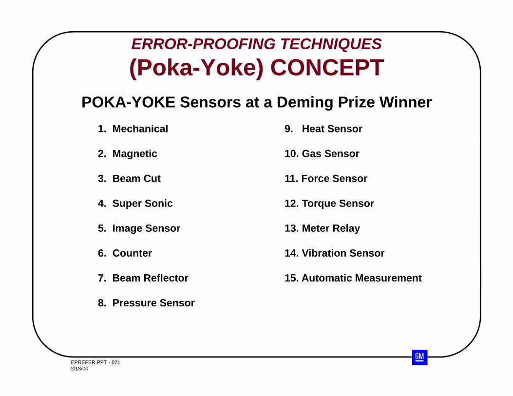
POKA-YOKE Sensors at a Deming Prize Winner1. Mechanical 9. Heat Sensor
2. Magnetic 10. Gas Sensor
3. Beam Cut 11. Force Sensor
4. Super Sonic 12. Torque Sensor
5. Image Sensor 13. Meter Relay
6. Counter 14. Vibration Sensor
7. Beam Reflector 15. Automatic Measurement
8. Pressure Sensor
EPREFER.PPT - 0222/13/00
ERROR-PROOFING TECHNIQUES(Poka-Yoke) CONCEPT
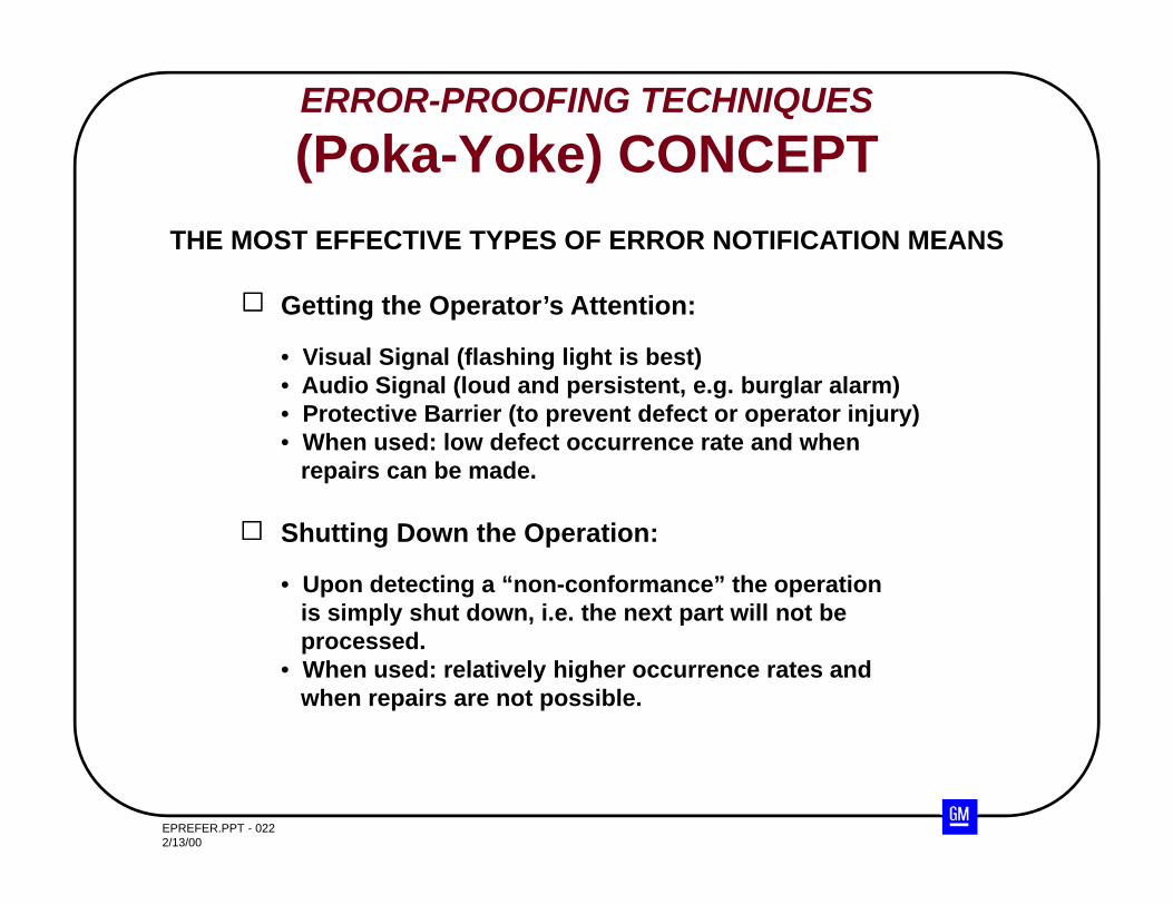
THE MOST EFFECTIVE TYPES OF ERROR NOTIFICATION MEANS
Getting the Operator’s Attention:
• Visual Signal (flashing light is best)• Audio Signal (loud and persistent, e.g. burglar alarm)• Protective Barrier (to prevent defect or operator injury)• When used: low defect occurrence rate and when
repairs can be made.
Shutting Down the Operation:
• Upon detecting a “non-conformance” the operationis simply shut down, i.e. the next part will not beprocessed.
• When used: relatively higher occurrence rates andwhen repairs are not possible.
EPREFER.PPT - 0232/13/00
ERROR-PROOFING TECHNIQUES(Poka-Yoke) CONCEPT
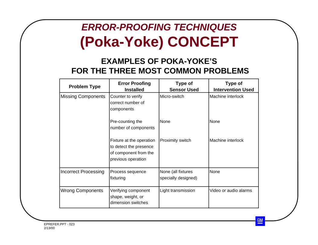
Problem Type Error ProofingInstalled
Type ofSensor Used
Type ofIntervention Used
Missing Components Counter to verify Micro-switch Machine interlockcorrect number ofcomponents
Pre-counting the None Nonenumber of components
Fixture at the operation Proximity switch Machine interlockto detect the presenceof component from theprevious operation
Incorrect Processing Process sequence None (all fixtures Nonefixturing specially designed)
Wrong Components Verifying component Light transmission Video or audio alarmsshape, weight, ordimension switches
EXAMPLES OF POKA-YOKE’SFOR THE THREE MOST COMMON PROBLEMS
EPREFER.PPT - 0242/13/00
ERROR-PROOFING TECHNIQUES(Poka-Yoke) CONCEPT
What is the best method for sensing fluid levelsfor a machine?
What is the best method for sensing magnets forelectric motors?
What are three possible methods for sensing burson a cylinder bore?
What is the best method for detecting the presenceof an O-ring?
BEST SENSING IDEAS
EPREFER.PPT - 0252/13/00
Four Categories of Errors - Questions to Ask????
Missing Parts Is there a model mix such that some models require a part
while others require nothing at all in that location?
Is the part assembled as a small part after some main activity?
Is the part difficult to see after being assembled?
EPREFER.PPT - 0262/13/00
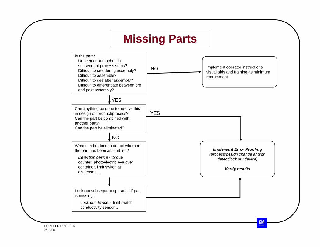
Missing PartsIs the part :
Unseen or untouched in subsequent process steps?Difficult to see during assembly?Difficult to assemble?Difficult to see after assembly?Difficult to differentiate between pre and post assembly?
Can anything be done to resolve this in design of product/process?Can the part be combined with another part?Can the part be eliminated?
What can be done to detect whether the part has been assembled?
Detection device - torque counter, photoelectric eye over container, limit switch at dispenser,....
Lock out subsequent operation if part is missing.
Lock out device - limit switch, conductivity sensor...
Implement operator instructions, visual aids and training as minimum requirement
YES
NO
NO
Implement Error Proofing(process/design change and/or
detect/lock out device)
Verify results
YES
EPREFER.PPT - 0272/13/00
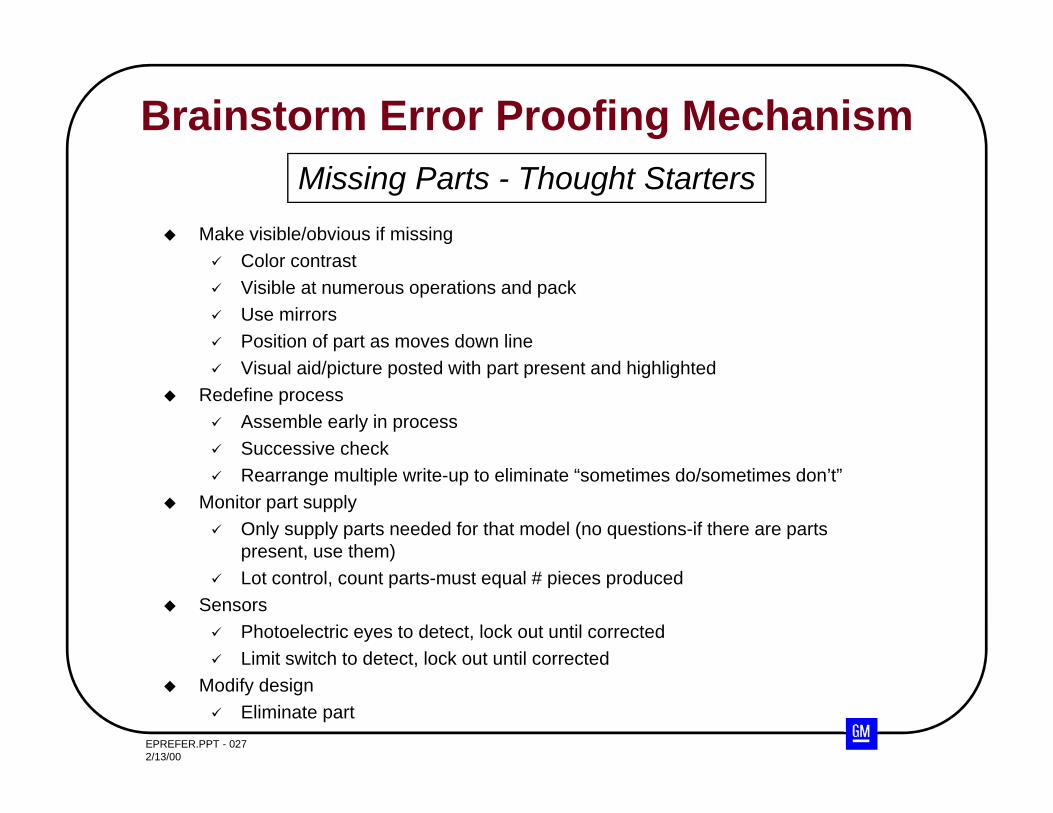
Brainstorm Error Proofing Mechanism
Make visible/obvious if missing Color contrast Visible at numerous operations and pack Use mirrors Position of part as moves down line Visual aid/picture posted with part present and highlighted
Redefine process Assemble early in process Successive check Rearrange multiple write-up to eliminate “sometimes do/sometimes don’t”
Monitor part supply Only supply parts needed for that model (no questions-if there are parts
present, use them) Lot control, count parts-must equal # pieces produced
Sensors Photoelectric eyes to detect, lock out until corrected Limit switch to detect, lock out until corrected
Modify design Eliminate part
Missing Parts - Thought Starters
EPREFER.PPT - 0282/13/00
Misassembled Parts Is the operation difficult for the operator to see as they
perform the job?
Is there an assembly or positioning operation that can be completed incorrectly?
Four Categories of Errors-Questions to Ask????
EPREFER.PPT - 0292/13/00
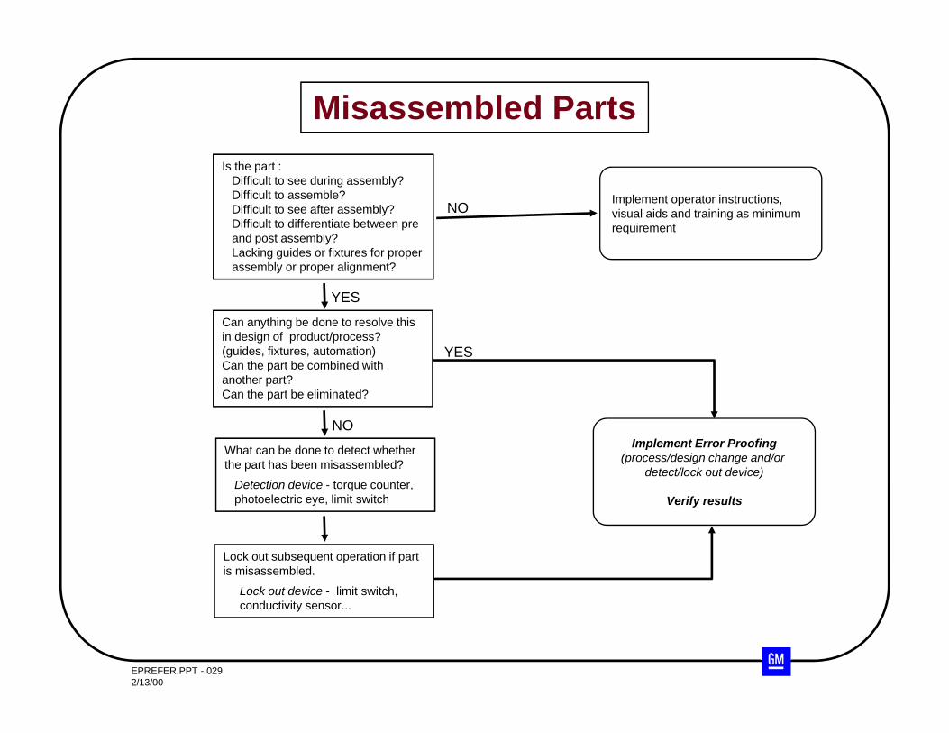
Misassembled PartsIs the part :
Difficult to see during assembly?Difficult to assemble?Difficult to see after assembly?Difficult to differentiate between pre and post assembly?Lacking guides or fixtures for proper assembly or proper alignment?
Can anything be done to resolve this in design of product/process?(guides, fixtures, automation)Can the part be combined with another part?Can the part be eliminated?
What can be done to detect whether the part has been misassembled?
Detection device - torque counter, photoelectric eye, limit switch
Lock out subsequent operation if part is misassembled.
Lock out device - limit switch, conductivity sensor...
Implement operator instructions, visual aids and training as minimum requirement
YES
NO
NOImplement Error Proofing
(process/design change and/or detect/lock out device)
Verify results
YES
EPREFER.PPT - 0302/13/00
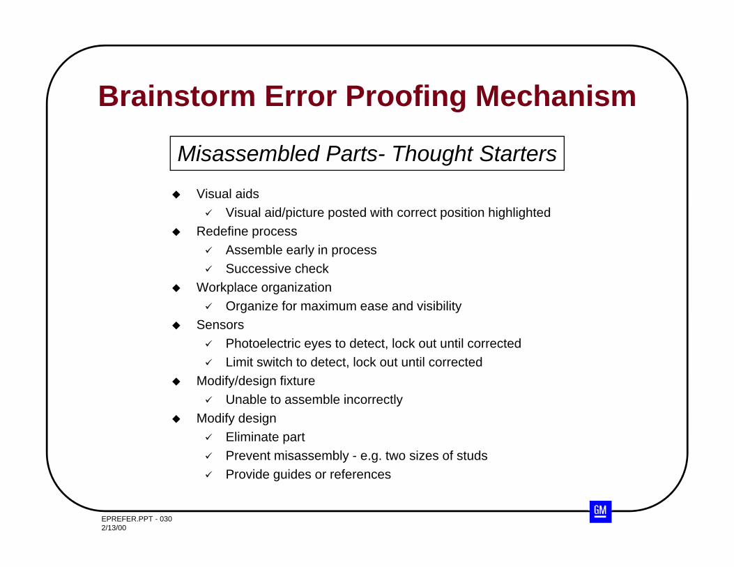
Brainstorm Error Proofing Mechanism
Visual aids Visual aid/picture posted with correct position highlighted
Redefine process Assemble early in process Successive check
Workplace organization Organize for maximum ease and visibility
Sensors Photoelectric eyes to detect, lock out until corrected Limit switch to detect, lock out until corrected
Modify/design fixture Unable to assemble incorrectly
Modify design Eliminate part Prevent misassembly - e.g. two sizes of studs Provide guides or references
Misassembled Parts- Thought Starters
EPREFER.PPT - 0312/13/00
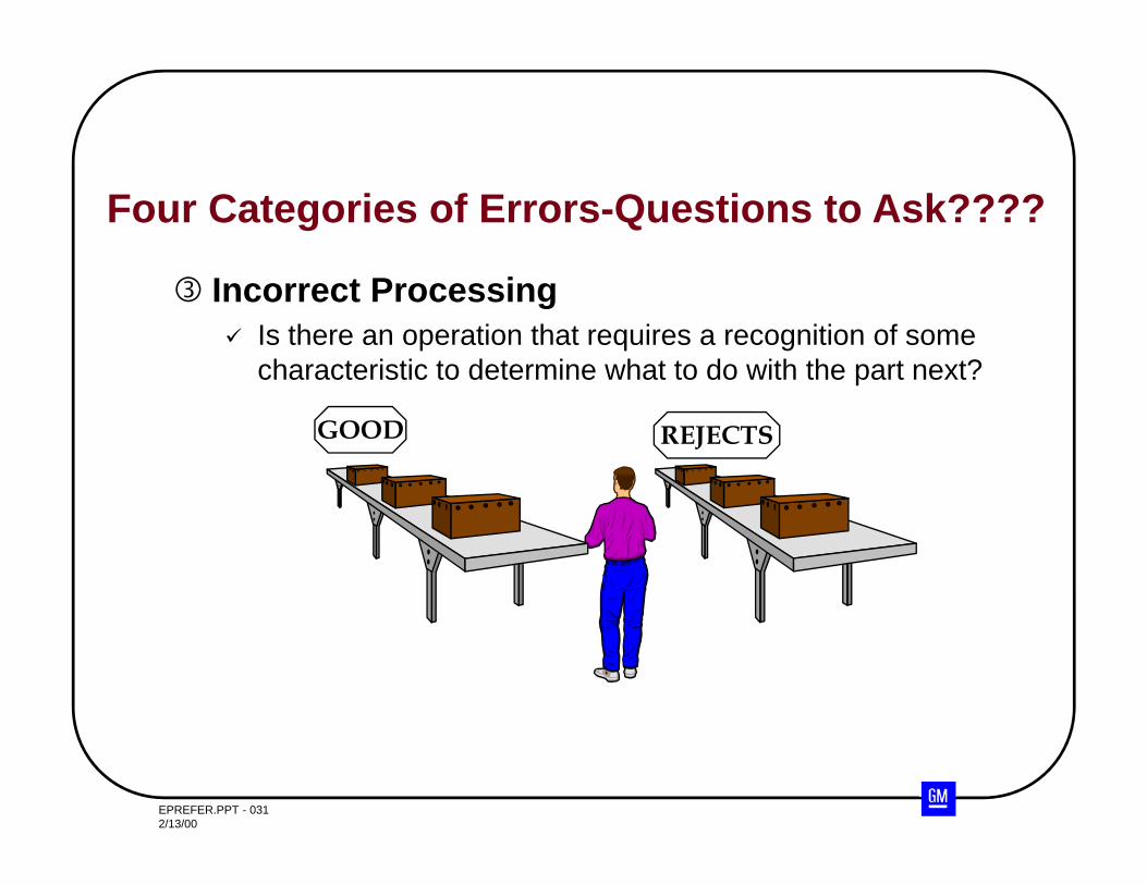
Incorrect Processing Is there an operation that requires a recognition of some
characteristic to determine what to do with the part next?
REJECTSGOOD
Four Categories of Errors-Questions to Ask????
EPREFER.PPT - 0322/13/00
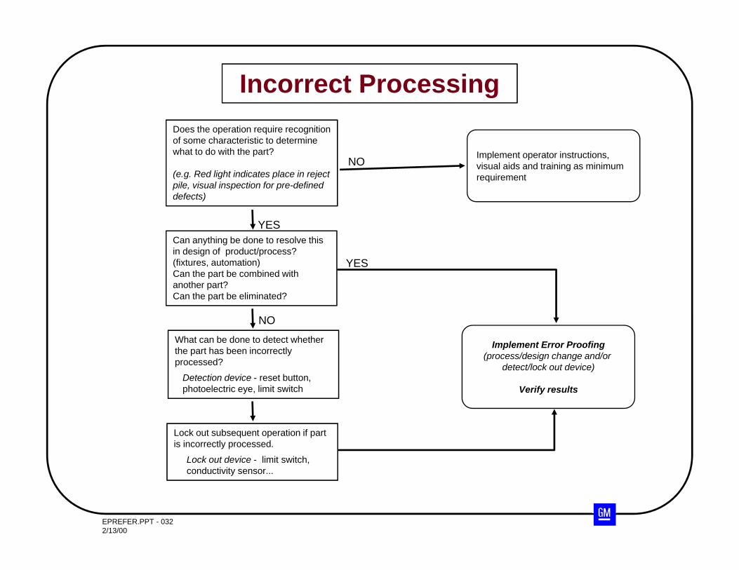
Incorrect ProcessingDoes the operation require recognition of some characteristic to determine what to do with the part?
(e.g. Red light indicates place in reject pile, visual inspection for pre-defined defects)
Can anything be done to resolve this in design of product/process?(fixtures, automation)Can the part be combined with another part?Can the part be eliminated?
What can be done to detect whether the part has been incorrectly processed?
Detection device - reset button,photoelectric eye, limit switch
Lock out subsequent operation if part is incorrectly processed.
Lock out device - limit switch, conductivity sensor...
Implement operator instructions, visual aids and training as minimum requirement
YES
NO
NO
Implement Error Proofing(process/design change and/or
detect/lock out device)
Verify results
YES
EPREFER.PPT - 0332/13/00
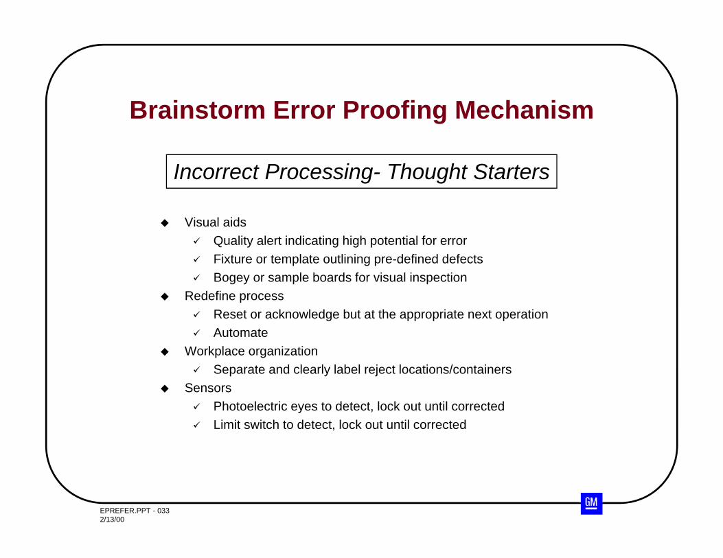
Brainstorm Error Proofing Mechanism
Visual aids Quality alert indicating high potential for error Fixture or template outlining pre-defined defects Bogey or sample boards for visual inspection
Redefine process Reset or acknowledge but at the appropriate next operation Automate
Workplace organization Separate and clearly label reject locations/containers
Sensors Photoelectric eyes to detect, lock out until corrected Limit switch to detect, lock out until corrected
Incorrect Processing- Thought Starters
EPREFER.PPT - 0342/13/00
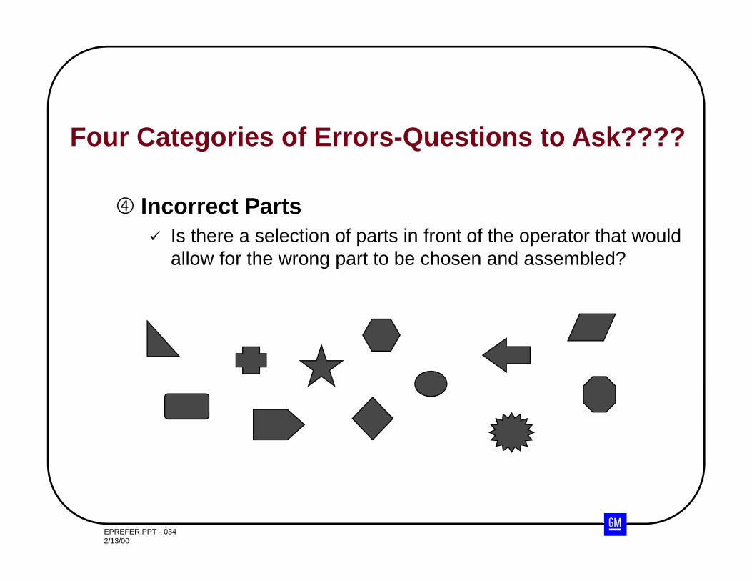
Incorrect Parts Is there a selection of parts in front of the operator that would
allow for the wrong part to be chosen and assembled?
Four Categories of Errors-Questions to Ask????
EPREFER.PPT - 0352/13/00
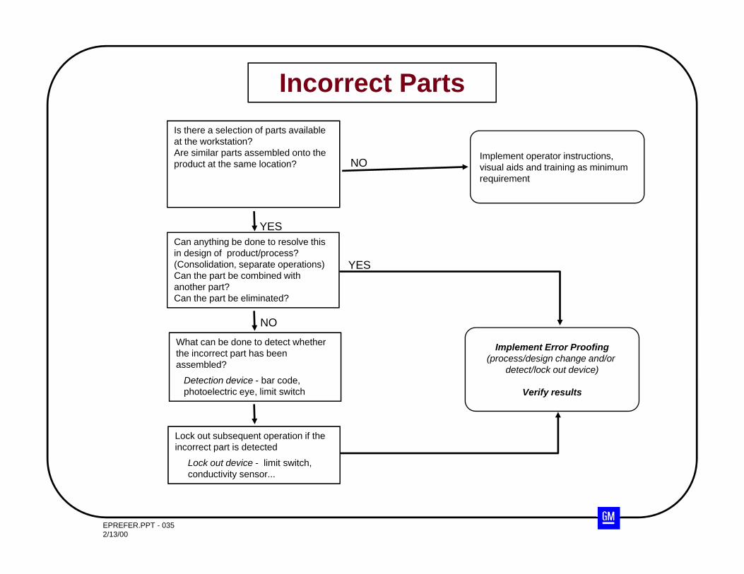
Incorrect PartsIs there a selection of parts available at the workstation?Are similar parts assembled onto the product at the same location?
Can anything be done to resolve this in design of product/process?(Consolidation, separate operations)Can the part be combined with another part?Can the part be eliminated?
What can be done to detect whether the incorrect part has been assembled?
Detection device - bar code,photoelectric eye, limit switch
Lock out subsequent operation if the incorrect part is detected
Lock out device - limit switch, conductivity sensor...
Implement operator instructions, visual aids and training as minimum requirement
YES
NO
NO
Implement Error Proofing(process/design change and/or
detect/lock out device)
Verify results
YES
EPREFER.PPT - 0362/13/00
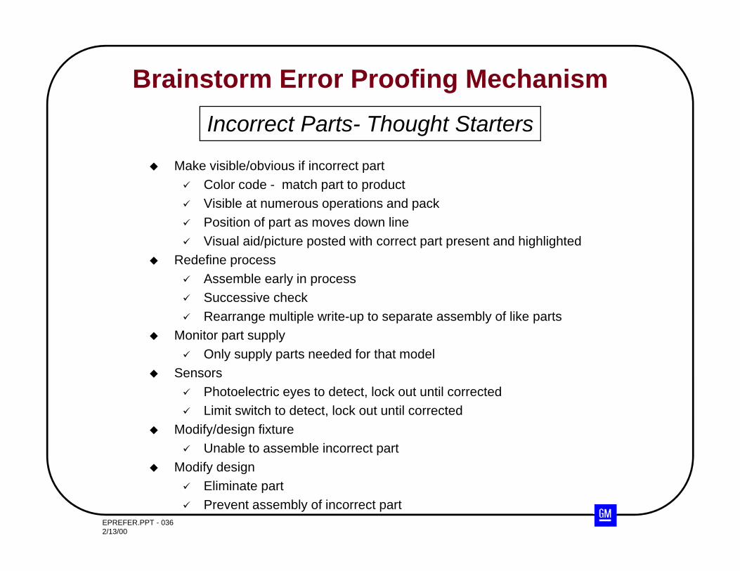
Brainstorm Error Proofing Mechanism
Make visible/obvious if incorrect part Color code - match part to product Visible at numerous operations and pack Position of part as moves down line Visual aid/picture posted with correct part present and highlighted
Redefine process Assemble early in process Successive check Rearrange multiple write-up to separate assembly of like parts
Monitor part supply Only supply parts needed for that model
Sensors Photoelectric eyes to detect, lock out until corrected Limit switch to detect, lock out until corrected
Modify/design fixture Unable to assemble incorrect part
Modify design Eliminate part Prevent assembly of incorrect part
Incorrect Parts- Thought Starters
EPREFER.PPT - 0372/13/00
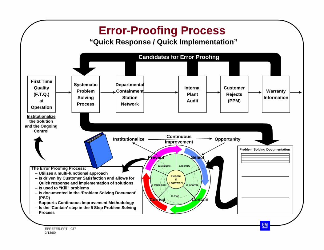
The Error Proofing Process:– Utilizes a multi-functional approach– Is driven by Customer Satisfaction and allows for
Quick response and implementation of solutions– Is used to “Kill” problems– Is documented in the ‘Problem Solving Document’
(PSD)– Supports Continuous Improvement Methodology– Is the ‘Contain’ step in the 5 Step Problem Solving
Process
People&
Teamwork
5. Evaluate 1. Identify
2. Analyze
3. Plan
4. Implement
Prevent Select
ContainCorrect
Error-Proofing Process“Quick Response / Quick Implementation”
Institutionalizethe Solution
and the OngoingControl
Institutionalize ContinuousImprovement Opportunity
Problem Solving Documentation
First TimeQuality(F.T.Q.)
atOperation
DepartmentalContainment
StationNetwork
InternalPlantAudit
CustomerRejects(PPM)
SystematicProblemSolvingProcess
Candidates for Error Proofing
WarrantyInformation
EPREFER.PPT - 0382/13/00
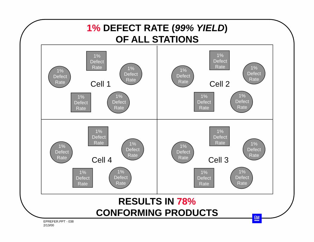
1% DEFECT RATE (99% YIELD)OF ALL STATIONS
RESULTS IN 78%CONFORMING PRODUCTS
Cell 1
Cell 3
Cell 2
Cell 4
1%DefectRate
1%DefectRate
1%DefectRate
1%DefectRate
1%DefectRate
1%DefectRate
1%DefectRate
1%DefectRate
1%DefectRate
1%DefectRate
1%DefectRate
1%DefectRate
1%DefectRate
1%DefectRate
1%DefectRate
1%DefectRate
1%DefectRate
1%DefectRate
1%DefectRate
1%DefectRate
EPREFER.PPT - 0392/13/00
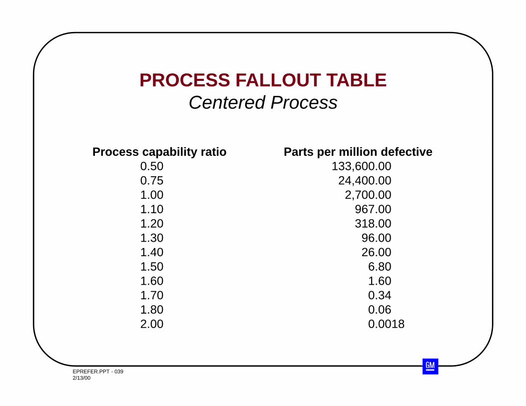
PROCESS FALLOUT TABLECentered Process
Process capability ratio Parts per million defective0.50 133,600.000.75 24,400.001.00 2,700.001.10 967.001.20 318.001.30 96.001.40 26.001.50 6.801.60 1.601.70 0.341.80 0.062.00 0.0018
EPREFER.PPT - 0402/13/00
DIDN’T WASHHANDS
EPREFER.PPT - 0412/13/00
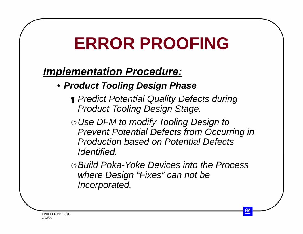
Implementation Procedure:• Product Tooling Design Phase
¶ Predict Potential Quality Defects during Product Tooling Design Stage.
Use DFM to modify Tooling Design to Prevent Potential Defects from Occurring in Production based on Potential Defects Identified.
Build Poka-Yoke Devices into the Process where Design “Fixes” can not be Incorporated.
ERROR PROOFING
EPREFER.PPT - 0422/13/00
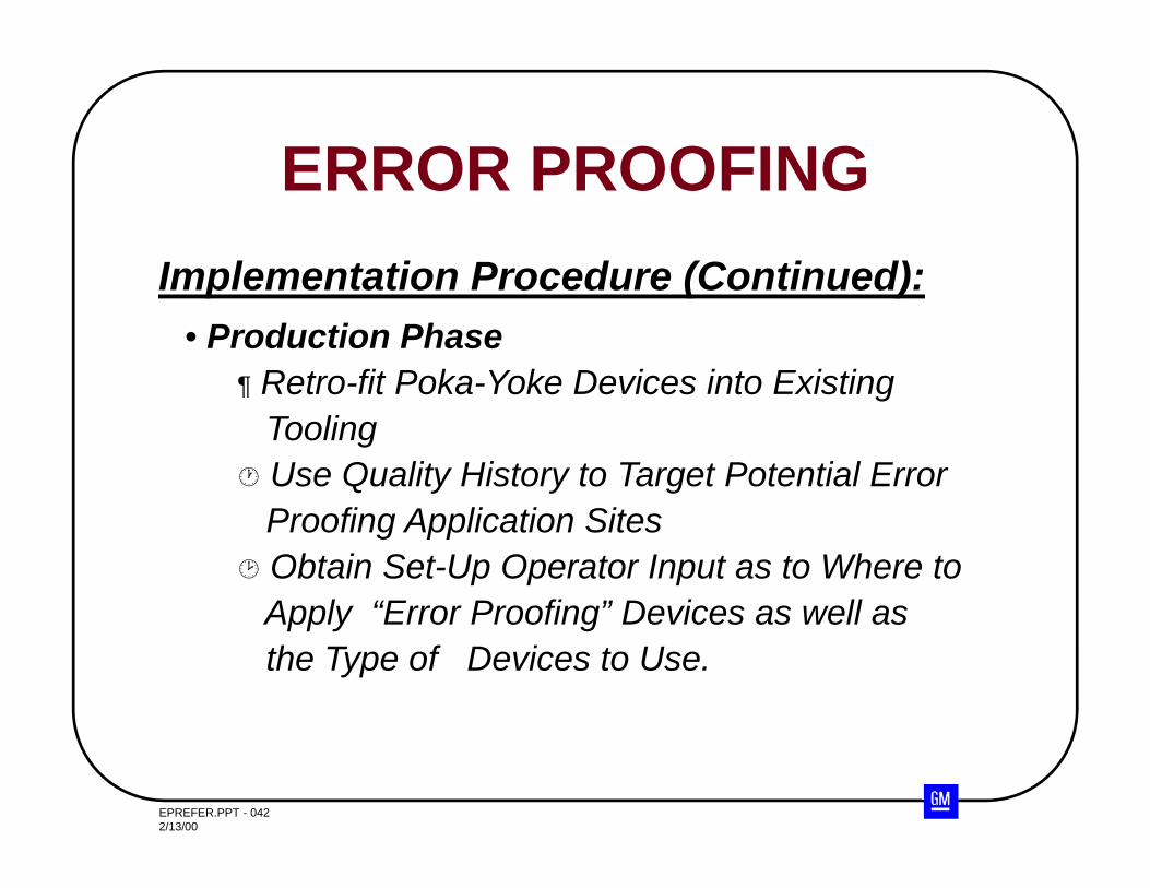
• Production Phase¶ Retro-fit Poka-Yoke Devices into Existing
Tooling Use Quality History to Target Potential Error
Proofing Application Sites Obtain Set-Up Operator Input as to Where to
Apply “Error Proofing” Devices as well asthe Type of Devices to Use.
Implementation Procedure (Continued):
ERROR PROOFING
EPREFER.PPT - 0432/13/00
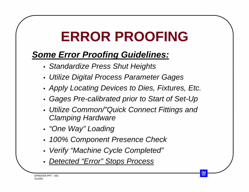
Some Error Proofing Guidelines:• Standardize Press Shut Heights• Utilize Digital Process Parameter Gages• Apply Locating Devices to Dies, Fixtures, Etc.• Gages Pre-calibrated prior to Start of Set-Up• Utilize Common/”Quick Connect Fittings and
Clamping Hardware• “One Way” Loading• 100% Component Presence Check• Verify “Machine Cycle Completed”• Detected “Error” Stops Process
ERROR PROOFING
EPREFER.PPT - 0442/13/00
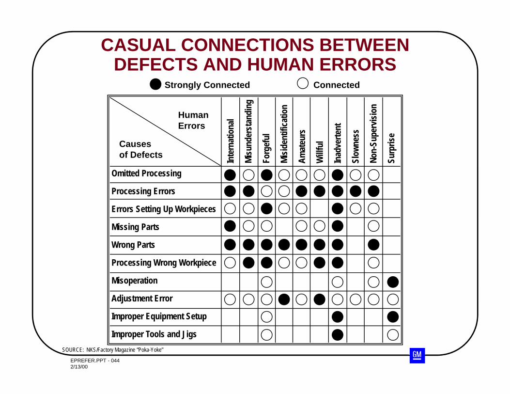
CASUAL CONNECTIONS BETWEEN DEFECTS AND HUMAN ERRORS
Causesof Defects
Omitted Processing
Processing Errors
Errors Setting Up Workpieces
Missing Parts
Wrong Parts
Processing Wrong Workpiece
Misoperation
Adjustment Error
Improper Equipment Setup
Improper Tools and Jigs
HumanErrors
Inte
rnat
iona
l
Mis
unde
rsta
ndin
g
Forg
eful
Mis
iden
tific
atio
n
Am
ateu
rs
Will
ful
Inad
vert
ent
Slow
ness
Non
-Sup
ervi
sion
Surp
rise
Strongly Connected Connected
SOURCE: NKS/Factory Magazine “Poka-Yoke”