es074 1030 3us - argo-hytos.com · description characteristics application to be installed in the...
TRANSCRIPT
10.30-4us
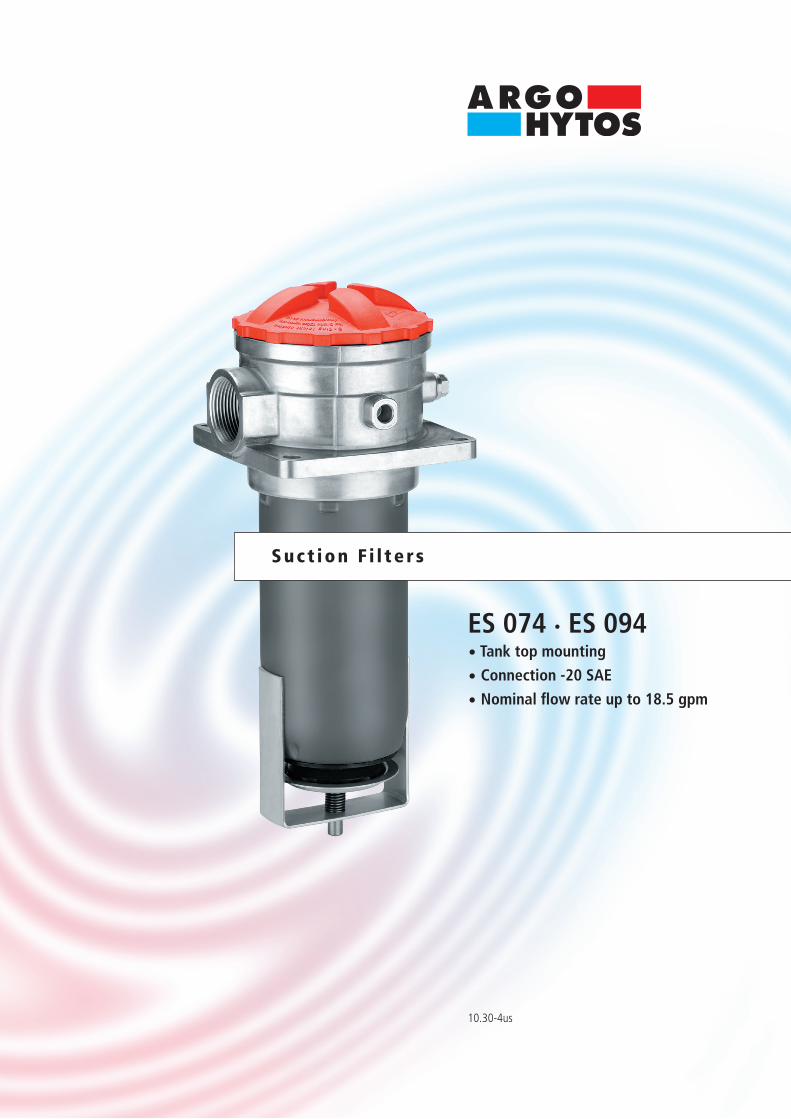
ES 074 · ES 094· Tank top mounting
· Connection -20 SAE
· Nominal fl ow rate up to 18.5 gpm
Suct ion F i l te rs

Descr i p t ion
Ch arac ter i s t i c s
ApplicationTo be installed in the suction line of the pumps of hydraulic systems or upstream of the charge pumps of hydrostatic drives.
Performance featuresProtection against wear: By means of filter elements that, in full-flow filtration, meet even the highest demands regarding cleanliness classes.Protection againstmalfunction: By means of full-flow filtration in the system return, the pumps above all are protected from dirt particles remaining in the system after assembly, repairs, or which are generated by wear or enter the system from outside.
Special featuresBy-pass valve: The location close to the suction inlet prevents dirt particles retained by the filter element from entering into the clean oil side.Filter element locking valve: Ensures that dirt accumulated in the filter element is removed together with the element and cannot return to the tank.Foot valve: When the screw-on cap is removed for maintenance, the foot valve closes automatically. This makes it possible to service the filter even if it is submerged below the oil level in a full tank.
Filter elementsFlow direction from center to outside. The star-shaped pleating of the filter material results in:• large filter surfaces• low pressure drop• high dirt-holding capacities• long service lifeIn filters with a magnetic system, the ferromagnetic particles in the fluid pass first through a strong magnetic field and are separated.
Filter maintenanceBy using a clogging indicator the correct moment for maintenance is stated and guarantees the optimum utilization of the filter life.
MaterialsScrew-on cap: Polyester, GF reinforcedFilter head: Aluminum alloyFilter bowl: SteelSeals: NBR (FKM on request) EXAPOR®MAX 2 - inorganic microfibre webFilter media: Paper – cellulose web, impregnated with resin Stainless steel wire mesh (1.4301) AccessoriesElectrical and optical clogging indicators are available on request. Dimensions and technical data see catalog sheet 60.20.
Nominal flow rateUp to 18.5 gpm (see Selection Chart, column 2)The nominal flow rates indicated by ARGO-HYTOS are based on the following features:• closed by-pass valve at ν ≤ 930 SUS• element service life > 1,000 operating hours at an average fluid contamination of 0.27 g per gpm flow volume• flow velocity in the connection lines ≤ 4.9 ft/s If units not equipped with a bypass valve are used in hydrostatic drives, the recommendations regarding their technical application given on catalog sheet 10.310 should be observed. Connection Threaded ports according to SAE standard J514. Sizes see Selection Chart, column 6 (other port threads on request) Filter fineness 16 µm(c) ... 30 µm(c)β-values according ISO 16889(see Selection Chart, column 4 and diagram Dx)
Dirt-holding capacityValues in g test dust ISO MTD according to ISO 16889 (see Selection Chart, column 5)
Hydraulic fluids Mineral oil and biodegradable fluids (HEES and HETG, see info-sheet 00.20).
Temperature range - 22 °F ... + 212 °F (temporary - 40 °F ... + 248 °F)
Viscosity at nominal flow rate • at operating temperature: ν < 280 SUS• start-up viscosity: determine ν
max observing the permissible pressure at the pump inlet according to diagram D; determine ∆p as a function of the viscosity (take pressure loss in connection lines into account!) • at initial operation of units equipped with a bypass valve: The recommended starting viscosity can be read from the diagram D (pressure drop as a function of the kinematic viscosity) as follows: Find the 70 % ∆p of the cracking pressure of the by-pass valve on the vertical axis. Draw a horizontal line so that it inter- sects the ∆p curve at a point. Read this point on the horizontal axis for the viscosity.
Mounting position Vertical mounting to be preferred, suction opening pointing downwards, versions equipped with foot valve for horizontal mounting also.

D2
D1∆p
[psi]
∆p [p
si]
∆p [p
si]
∆p [p
si]
ν [SUS]Q [gpm]
Q [gpm] ν [SUS]
Dx
0.7
5.3 10.6 15.8 21.1 26.4
1.5
2.2
1.5
930 1860 2790 3720 4650
2.9
4.4
5.8
7.3
0.7
5.3 10.6 15.8 21.1 26.4
1.5
2.2
1.5
930 1860 2790 3720 4650
2.9
4.4
5.8
7.3
D i agrams
∆p-curves for complete filters in Selection Chart, column 3
Filter fineness curves in Selection Chart, column 4
Filtration ratio β as a function of particle size x obtained by the Multi-Pass-Test according to ISO 16889
Particle size x [µm] (for particles larger than the given particle size x)
Filtr
atio
n ra
tio β
for p
artic
les
> x
µm
Effic
ienc
y [%
]
Pressure drop as a function of the flow volumeat ν = 162 SUS (0 = casing empty)
Pressure drop as a function of the kinematic viscosityat nominal flow
Pressure drop as a function of the flow volumeat ν = 162 SUS (0 = casing empty)
Pressure drop as a function of the kinematic viscosity at nominal flow
The abbreviations represent the following β-values resp. finenesses:
For EXAPOR®MAX 2 and Paper elements: 16EX2 = β16 (c) = 200 EXAPOR®MAX 2 30P = β30 (c) = 200 Paper 50P = β50 (c) = 200 PaperBased on the structure of the filter media of the 30P and 50P paper elements, deviations from the printed curves are quite probable.
For screen elements: 40S = screen material with mesh size 40 µm 60S = screen material with mesh size 60 µm 100S = screen material with mesh size 100 µmTolerances for mesh size according to DIN 4189.
For special applications, finenesses differing from these curves are also available by using special composed filter material.

All filters are delivered with a plugged clogging indicator connection G¼. As clogging indicators either manometers or vacuum switches can be used.
For the appropriate clogging indicator see catalog sheet 60.20.
Remarks:• The start of the red area respectively the actuating pressure of the vacuum switch has always to be higher than the cracking pressure of the by-pass valve (see Selection Chart, column 7).• Clogging indicators are optional and always delivered detached from the filter. • The filters listed in this chart are standard filters. Other designs available on request.
Se l ec t ion Char t
Part No.
Remarks
Nominal flow rate
Connection B
Dirt-holding ca
pacity
Fi
lter su
rface in ( )
Pressure d
rop see
diagram D/cu
rve no.
Symbol
Foot valve
Cracking pres
sure of by-p
ass
Replacement filter
element
Pa
rt No.
Weight
Filter fi
neness se
e diagr. D
x
ES 074-68017 10.61 D1/1 16EX2 26 -202 - • 2 V2.0923-07 5.3 - ES 074-6151 11.91 D1/2 30P 23 -202 - • 2 P2.0923-01 5.3 -
ES 094-68017 15.91 D2/1 16EX2 40 -202 - • 2 V2.0933-08 7.1 -
ES 094-61117 18.51 D2/2 30P 34 -202 - • 2 P2.0933-01 7.1 -
1 Those values apply when used in hydrostatic drives and instructions in catalogue sheet 10.310 have to be observed 2 corresponds to 15/8 -12 UN-2B
1 2 3 4 5 6 7 8 9 10 11 12
gpm g psi lbsSAE
1 2 3 4 5 6
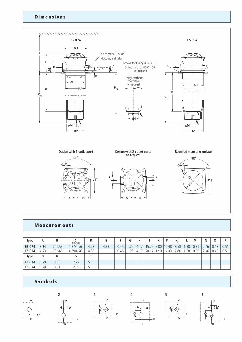
D i m en s ions
Design with 1 outlet port Design with 2 outlet portson request
Required mounting surface
Design without foot valve on request
ES 074 ES 094
Connection G¼ forclogging indicator
Groove for O-ring 4.96 x 0.16O-ring part no. N007.1264
on request
M easu rements
Type A B C D E F G H I K K1 K2 L M N O P
ES 074 3.94 -20 SAE 4.37/4.76 4.98 4.33 0.45 1.26 4.17 15.75 7.80 10.08 8.58 1.38 0.39 2.46 0.43 0.51 ES 094 4.53 -20 SAE 4.69/4.76 4.98 - 0.45 1.26 4.17 20.67 12.0 14.33 12.80 1.38 0.39 2.46 0.43 0.51 Type Q R S T
ES 074 6.50 3.25 2.99 5.55 ES 094 6.50 3.01 2.99 5.55
Sy mbol s
min./max.

7
6
5
4
2
1 3a 3b
Spare Par t s
The functions of the complete filters as well as the outstanding features of the filter elements assured by ARGO-HYTOS can only be guaranteed if original ARGO-HYTOS spare parts are used.
Pos. Designation Part No. 1 Screw-on cap with Pos. 2 ES 074.1212 2 O-ring 3.94 x 0.16 N007.1004 3a Screw-on cap with Pos. 2 for ES 074 (without by-pass) ES 074.1213 for ES 094 (without by-pass) ES 094.1212 for ES 094 (with by-pass) ES 094.1213 3b Screw-on cap with Pos. 2 including magnetic system for ES 074 (with by-pass) ES 074.1205 4 Filter element see Chart / col. 10 5 Valve cone ES 074.0202 6 O-ring 4.96 x 0.16 * N007.1264 7 Rubber ring N042.7401
* not included in basic equipment
Quality management according to DIN EN ISO 9001
To ensure constant quality in production and operation, ARGO-HYTOSfilter elements undergo strict controls and tests according to the following ISO standards:
ISO 2941 Verification of collapse/burst pressure ratingISO 2942 Verification of fabrication integrity (Bubble Point Test)ISO 2943 Verification of material compatibility with fluids
ISO 3968 Evaluation of pressure drop versus flow characteristicsISO 16889 Multi-Pass-Test (evaluation of filter fineness and dirt-holding capacity) ISO 23181 Determination of resistance to flow fatigue using high viscosity fluid
Various quality controls during the production process guarantee the leakfree function and solidity of our filters.
Q u a l i ty Assurance
Our engineers will be glad to advise you in questions concerning filter application, selection as well as the cleanliness class of the filtered medium attainable under practical operating conditions.
Illustrations may sometimes differ from the original. ARGO-HYTOS is not responsible for any unintentional mistake in this specification sheet.
Subject to change10.30-4us · 0714
We produce fluid power solutionsARGO-HYTOS Inc. · P.O. Box 28 · Bowling Green, OH 43402 · USAPhone: +1-419-353-6070 · Fax: +1-419-354-3496 · [email protected] · www.argo-hytos.com