escalade - server im online-shop konfigurieren und online kaufen
TRANSCRIPT

Escalade®
ATA RAID ControllerSupports the 7000 and 8000 Seriesand Release 7.7.x of the 3ware Software
PN 900-0041-00December, 2003
User
Gu
ide

Copyright ©2003 3ware, Inc. All rights reserved. No part of this publication may be reproduced, stored in a retrieval system, or transmitted in any form by any means, electronic, mechanical, photocopying, recording or otherwise, without the proper written consent of 3ware, Inc., 455 West Maude Ave., Sunnyvale, CA 94085.
Trademarks3ware, Escalade, and 3DM are all registered trademarks of 3ware, Inc. The 3ware logo, StorSwitch, TwinStor, and R5 Fusion are all trademarks of 3ware, Inc. All other trademarks herein are property of their respective owners.
Disclaimer3ware, Inc. assumes no responsibility for errors or omissions in this docu-ment, nor does 3ware, Inc. make any commitment to update the information contained herein.

www.3ware.com i
List of Figures . . . . . . . . . . . . . . . . . . . . . . . . . . . . . . . . . . . . . . . . . . . . . v
Before You Begin . . . . . . . . . . . . . . . . . . . . . . . . . . . . . . . . . . . . . . . . . . . 1Features . . . . . . . . . . . . . . . . . . . . . . . . . . . . . . . . . . . . . . . . . . . . . . . . . . . . . . . . . 1
Escalade 7000 Parallel ATA Family . . . . . . . . . . . . . . . . . . . . . . . . . . . . . . . . . . 1Escalade 8000 Serial ATA Family . . . . . . . . . . . . . . . . . . . . . . . . . . . . . . . . . . . . 2
Package Contents . . . . . . . . . . . . . . . . . . . . . . . . . . . . . . . . . . . . . . . . . . . . . . . . . 3Escalade 7000 series Parallel ATA RAID Controller . . . . . . . . . . . . . . . . . . . . . . 3Escalade 8000 series Serial ATA RAID Controller . . . . . . . . . . . . . . . . . . . . . . . 3
Tools Required . . . . . . . . . . . . . . . . . . . . . . . . . . . . . . . . . . . . . . . . . . . . . . . . . . . . 4System Requirements . . . . . . . . . . . . . . . . . . . . . . . . . . . . . . . . . . . . . . . . . . . . . . 4Personal Safety . . . . . . . . . . . . . . . . . . . . . . . . . . . . . . . . . . . . . . . . . . . . . . . . . . . 4Protecting Equipment and Data . . . . . . . . . . . . . . . . . . . . . . . . . . . . . . . . . . . . . . . 4ESD Precautions . . . . . . . . . . . . . . . . . . . . . . . . . . . . . . . . . . . . . . . . . . . . . . . . . . 5Mechanical Concerns . . . . . . . . . . . . . . . . . . . . . . . . . . . . . . . . . . . . . . . . . . . . . . . 5
Introduction . . . . . . . . . . . . . . . . . . . . . . . . . . . . . . . . . . . . . . . . . . . . . . . 7Unmatched reliability and performance . . . . . . . . . . . . . . . . . . . . . . . . . . . . . . . 7Escalade Serial ATA Controller . . . . . . . . . . . . . . . . . . . . . . . . . . . . . . . . . . . . . . 8RAID increases performance and adds redundancy . . . . . . . . . . . . . . . . . . . . . 8RAID 0 arrays maximize performance and capacity . . . . . . . . . . . . . . . . . . . . . . 8RAID 1 arrays offer fault tolerance . . . . . . . . . . . . . . . . . . . . . . . . . . . . . . . . . . . 9TwinStorTM Technology adds performance to 3ware’s mirrored disk arrays . . . 9RAID 10 arrays maximize performance and fault
tolerance . . . . . . . . . . . . . . . . . . . . . . . . . . . . . . . . . . . . . . . . . . . . . . . . . . . . 9RAID 5 arrays optimize performance, fault tolerance, high capacity and storage
efficiency . . . . . . . . . . . . . . . . . . . . . . . . . . . . . . . . . . . . . . . . . . . . . . . . . . . 10R5 FusionTM Technology significantly improves RAID 5 write performance . . 11Configure and manage your disk arrays . . . . . . . . . . . . . . . . . . . . . . . . . . . . . . 11Background media scan and dynamic sector repair enhance data integrity . . . 12
Quick Installation Guide . . . . . . . . . . . . . . . . . . . . . . . . . . . . . . . . . . . . 14
3ware Hardware Installation . . . . . . . . . . . . . . . . . . . . . . . . . . . . . . . . . 17To remove an existing Escalade ATA RAID Controller . . . . . . . . . . . . . . . . . . . 17
Installing a Parallel ATA RAID Controller . . . . . . . . . . . . . . . . . . . . . . . . . . . . . . . 18Connect the interface cables to the Escalade ATA RAID Controller . . . . . . . . . 18Install the Escalade ATA RAID Controller in the computer . . . . . . . . . . . . . . . . 19Connect the drives to the interface cables . . . . . . . . . . . . . . . . . . . . . . . . . . . . 20
Installing a Serial ATA RAID Controller . . . . . . . . . . . . . . . . . . . . . . . . . . . . . . . . 21Connect the interface cables to the Escalade Serial ATA RAID Controller . . . . 21Connect the drives to the interface cables . . . . . . . . . . . . . . . . . . . . . . . . . . . . 22
Installing a Serial ATA RAID Controller with Multi-lane Internal Connectors . . . . 24Install the Controller with Multi-lane Internal Connectors in Your System . . . . 25Connect the Interface Cables . . . . . . . . . . . . . . . . . . . . . . . . . . . . . . . . . . . . . . 25
Table of Contents

ii 3ware Escalade ATA RAID Controller User Guide
Install the Drives . . . . . . . . . . . . . . . . . . . . . . . . . . . . . . . . . . . . . . . . . . . . . . . . 26Check your installation and close the case . . . . . . . . . . . . . . . . . . . . . . . . . . . . . 26Check motherboard boot sequence . . . . . . . . . . . . . . . . . . . . . . . . . . . . . . . . . . . 26
3ware Disk Array Configuration Utility . . . . . . . . . . . . . . . . . . . . . . . . 27Hot spare and hot swap . . . . . . . . . . . . . . . . . . . . . . . . . . . . . . . . . . . . . . . . . . . . 27
BIOS Screen . . . . . . . . . . . . . . . . . . . . . . . . . . . . . . . . . . . . . . . . . . . . . . . . . . . 28Invoking the 3ware BIOS tool . . . . . . . . . . . . . . . . . . . . . . . . . . . . . . . . . . . . . . . . 28Exiting the 3ware BIOS tool . . . . . . . . . . . . . . . . . . . . . . . . . . . . . . . . . . . . . . . . . 29Determining your configuration . . . . . . . . . . . . . . . . . . . . . . . . . . . . . . . . . . . . . . 29Displaying advanced details . . . . . . . . . . . . . . . . . . . . . . . . . . . . . . . . . . . . . . . . . 30Creating a disk array . . . . . . . . . . . . . . . . . . . . . . . . . . . . . . . . . . . . . . . . . . . . . . 31Determining your configuration . . . . . . . . . . . . . . . . . . . . . . . . . . . . . . . . . . . . . . 32Specifying a Hot Spare . . . . . . . . . . . . . . . . . . . . . . . . . . . . . . . . . . . . . . . . . . . . . 36Changing an existing configuration . . . . . . . . . . . . . . . . . . . . . . . . . . . . . . . . . . . 36Modifying a disk array . . . . . . . . . . . . . . . . . . . . . . . . . . . . . . . . . . . . . . . . . . . . . 36Deleting a disk array . . . . . . . . . . . . . . . . . . . . . . . . . . . . . . . . . . . . . . . . . . . . . . . 36How to maintain or verify a disk array . . . . . . . . . . . . . . . . . . . . . . . . . . . . . . . . . 37Rebuilding a mirrored disk array . . . . . . . . . . . . . . . . . . . . . . . . . . . . . . . . . . . . . 38Rebuilding a RAID 5 disk array . . . . . . . . . . . . . . . . . . . . . . . . . . . . . . . . . . . . . . 40
Windows Installation . . . . . . . . . . . . . . . . . . . . . . . . . . . . . . . . . . . . . . . 45Installing a drive to an existing ATA RAID controller . . . . . . . . . . . . . . . . . . . . . . 46
Boot the machine . . . . . . . . . . . . . . . . . . . . . . . . . . . . . . . . . . . . . . . . . . . . . . . 46Installing the ATA RAID controller while installing Windows 2000/XP/2003 . . . . . . . . . . . . . . . . . . . . . . . . . . . . . . . . . . . . 47
Create disk arrays . . . . . . . . . . . . . . . . . . . . . . . . . . . . . . . . . . . . . . . . . . . . . . . 47Installing with the initial operating system build . . . . . . . . . . . . . . . . . . . . . . . . 47Continue with Windows installation . . . . . . . . . . . . . . . . . . . . . . . . . . . . . . . . . . 47Reboot the machine . . . . . . . . . . . . . . . . . . . . . . . . . . . . . . . . . . . . . . . . . . . . . 48RAID array initialization . . . . . . . . . . . . . . . . . . . . . . . . . . . . . . . . . . . . . . . . . . 48Install the 3DM disk management utility . . . . . . . . . . . . . . . . . . . . . . . . . . . . . . 49
Installing the ATA RAID controller on systems that boot from a different device . 49Create disk arrays . . . . . . . . . . . . . . . . . . . . . . . . . . . . . . . . . . . . . . . . . . . . . . . 49Install the 3ware driver . . . . . . . . . . . . . . . . . . . . . . . . . . . . . . . . . . . . . . . . . . . 49Reboot the machine . . . . . . . . . . . . . . . . . . . . . . . . . . . . . . . . . . . . . . . . . . . . . 50RAID array initialization . . . . . . . . . . . . . . . . . . . . . . . . . . . . . . . . . . . . . . . . . . 50Install the 3DM disk management utility . . . . . . . . . . . . . . . . . . . . . . . . . . . . . . 51
Replacing an existing ATA RAID controller with a new version of the controller . 52Updating the 3ware driver . . . . . . . . . . . . . . . . . . . . . . . . . . . . . . . . . . . . . . . . . 52Installing/Upgrading the 3ware driver . . . . . . . . . . . . . . . . . . . . . . . . . . . . . . . . 54Remove the existing Escalade ATA RAID Controller
and install the new Escalade ATA RAID Controller . . . . . . . . . . . . . . . . . . . 59Reboot the machine . . . . . . . . . . . . . . . . . . . . . . . . . . . . . . . . . . . . . . . . . . . . . 59Install the 3DM disk management utility . . . . . . . . . . . . . . . . . . . . . . . . . . . . . . 59
Linux Installation . . . . . . . . . . . . . . . . . . . . . . . . . . . . . . . . . . . . . . . . . . 61Red Hat Linux Installation . . . . . . . . . . . . . . . . . . . . . . . . . . . . . . . . . . . . . . . . . . . 62
Installing the ATA RAID controller while installing Red Hat Linux . . . . . . . . . . . 62Installing the ATA RAID controller on systems that boot from a different device 64
SuSE Linux Installation . . . . . . . . . . . . . . . . . . . . . . . . . . . . . . . . . . . . . . . . . . . . . 68Installing the ATA RAID controller while installing SuSE Linux with YaST2 . . . 68Installing the ATA RAID controller on systems that boot from a different device 70
FreeBSD Installation . . . . . . . . . . . . . . . . . . . . . . . . . . . . . . . . . . . . . . . 73Installing the ATA RAID controller while installing FreeBSD . . . . . . . . . . . . . . . 74Installing the ATA RAID controller on systems that boot from a different device 75

www.3ware.com iii
Compiling the Driver (For experts only) . . . . . . . . . . . . . . . . . . . . . . . . . . . . . . 77
3DM Disk Management Utility . . . . . . . . . . . . . . . . . . . . . . . . . . . . . . . . . . . . . . . . . . . . . . . . . . . . 79Windows Installation . . . . . . . . . . . . . . . . . . . . . . . . . . . . . . . . . . . . . . . . . . . . . . . 80
Installing 3DM for Windows 2000/XP/2003 . . . . . . . . . . . . . . . . . . . . . . . . . . . . 80Linux Installation . . . . . . . . . . . . . . . . . . . . . . . . . . . . . . . . . . . . . . . . . . . . . . . . . . 81
Uninstalling 3DM . . . . . . . . . . . . . . . . . . . . . . . . . . . . . . . . . . . . . . . . . . . . . . . . 83Checking Array Status . . . . . . . . . . . . . . . . . . . . . . . . . . . . . . . . . . . . . . . . . . . . . 84
View status using your standard browser . . . . . . . . . . . . . . . . . . . . . . . . . . . . . 84Password setup . . . . . . . . . . . . . . . . . . . . . . . . . . . . . . . . . . . . . . . . . . . . . . . . 89Enable/disable password protection . . . . . . . . . . . . . . . . . . . . . . . . . . . . . . . . . 91Selecting background task rate . . . . . . . . . . . . . . . . . . . . . . . . . . . . . . . . . . . . . 91Selecting remote access . . . . . . . . . . . . . . . . . . . . . . . . . . . . . . . . . . . . . . . . . . 91Selecting cache options . . . . . . . . . . . . . . . . . . . . . . . . . . . . . . . . . . . . . . . . . . 91Event notification via e-mail . . . . . . . . . . . . . . . . . . . . . . . . . . . . . . . . . . . . . . . 92
Configuration and Array Maintenance Settings . . . . . . . . . . . . . . . . . . . . . . . . . . . . . . . . . . . . . . . . . . . . . . . . . . . . . . . . 92
Specifying a hot spare . . . . . . . . . . . . . . . . . . . . . . . . . . . . . . . . . . . . . . . . . . . 93Rebuilding a redundant array with a hot swap drive . . . . . . . . . . . . . . . . . . . . . 93Scheduling background tasks . . . . . . . . . . . . . . . . . . . . . . . . . . . . . . . . . . . . . . 94
Troubleshooting: Problems and Solutions . . . . . . . . . . . . . . . . . . . . . 97Hardware installation . . . . . . . . . . . . . . . . . . . . . . . . . . . . . . . . . . . . . . . . . . . . . . 97Software installation . . . . . . . . . . . . . . . . . . . . . . . . . . . . . . . . . . . . . . . . . . . . . . . 98Screen display messages . . . . . . . . . . . . . . . . . . . . . . . . . . . . . . . . . . . . . . . . . . 99
AEN Messages . . . . . . . . . . . . . . . . . . . . . . . . . . . . . . . . . . . . . . . . . . . . . . . . 100
Appendix A. Compliance and Conformity Statements . . . . . . . . . . 109Federal Communications Commission Radio Frequency Interference Statement 109Microsoft Windows Hardware Quality Lab (WHQL) . . . . . . . . . . . . . . . . . . . . . . 110European Community Conformity Statement . . . . . . . . . . . . . . . . . . . . . . . . . . . 110
Appendix B. Warranty, Technical Support and Service . . . . . . . . . . 111Limited Warranty . . . . . . . . . . . . . . . . . . . . . . . . . . . . . . . . . . . . . . . . . . . . . . . . . 111Exclusions . . . . . . . . . . . . . . . . . . . . . . . . . . . . . . . . . . . . . . . . . . . . . . . . . . . . . . 111State Law Provisions . . . . . . . . . . . . . . . . . . . . . . . . . . . . . . . . . . . . . . . . . . . . . 112Obtaining Warranty Protection . . . . . . . . . . . . . . . . . . . . . . . . . . . . . . . . . . . . . . 1123ware Technical Support and Services . . . . . . . . . . . . . . . . . . . . . . . . . . . . . . . 112Sales and ordering information . . . . . . . . . . . . . . . . . . . . . . . . . . . . . . . . . . . . . 113Feedback on this manual . . . . . . . . . . . . . . . . . . . . . . . . . . . . . . . . . . . . . . . . . . 113
Index . . . . . . . . . . . . . . . . . . . . . . . . . . . . . . . . . . . . . . . . . . . . . . . . . . . 115

iv 3ware Escalade ATA RAID Controller User Guide

www.3ware.com v
Figure 1. RAID 0 Configuration Example . . . . . . . . . . . . . . . . . . . . . . . . . 9Figure 2. RAID 1 Configuration Example . . . . . . . . . . . . . . . . . . . . . . . . . 9Figure 3. RAID 10 Configuration Example . . . . . . . . . . . . . . . . . . . . . . . 10Figure 4. RAID 5 Configuration Example . . . . . . . . . . . . . . . . . . . . . . . . 11Figure 5. 8-Port Escalade 750x-8 ATA RAID Controller Layout. . . . . . . 18Figure 6. 12-Port Escalade 850x-12 Serial ATA RAID Controller . . . . . 21Figure 7. 12-Port Escalade 8506-12MI Serial ATA RAID Controller . . . 24Figure 8. Multi-lane Cable (InfiniBand 4x, SFF-8470) . . . . . . . . . . . . . . 24Figure 9. 3ware BIOS Tool . . . . . . . . . . . . . . . . . . . . . . . . . . . . . . . . . . . 29Figure 10. Disk Array Configuration Main Display, RAID 1 Example . . . . 30Figure 11. Disk Array Advance Details Screen . . . . . . . . . . . . . . . . . . . . 31Figure 12. Selecting Drives for a Mirrored Array . . . . . . . . . . . . . . . . . . . 32Figure 13. Create Disk Array Display, RAID 0 Example. . . . . . . . . . . . . . 33Figure 14. Create Disk Array Display, RAID 5 Example. . . . . . . . . . . . . . 33Figure 15. BIOS Initialization Screen for RAID 5. . . . . . . . . . . . . . . . . . . 34Figure 16. Delete Disk Array Display . . . . . . . . . . . . . . . . . . . . . . . . . . . . 37Figure 17. Maintain Disk Array Display . . . . . . . . . . . . . . . . . . . . . . . . . . 38Figure 18. Degraded RAID 1 Array Drive When Not in Use. . . . . . . . . . . 39Figure 19. Degraded RAID 10 Array Drive When Not in Use. . . . . . . . . . 39Figure 20. Degraded RAID 5 Array Drive When Not in Use. . . . . . . . . . . 40Figure 21. Continue on Source Error Example. . . . . . . . . . . . . . . . . . . . . 41Figure 22. Select Available Drive to Replace Faulted Drive,
RAID 1 Example . . . . . . . . . . . . . . . . . . . . . . . . . . . . . . . . . . . 42Figure 23. Rebuild Array Status Display, RAID 1 Example . . . . . . . . . . . 42Figure 24. Found New Hardware Wizard . . . . . . . . . . . . . . . . . . . . . . . . . 49Figure 25. 3ware ATA RAID Controller Properties Display . . . . . . . . . . . 53Figure 26. Upgrade Driver Welcome Screen . . . . . . . . . . . . . . . . . . . . . . 54Figure 27. Upgrade/Install Device Driver . . . . . . . . . . . . . . . . . . . . . . . . . 54Figure 28. Select a Device Driver. . . . . . . . . . . . . . . . . . . . . . . . . . . . . . . 55Figure 29. Install From Disk . . . . . . . . . . . . . . . . . . . . . . . . . . . . . . . . . . . 56Figure 30. Select a Device Driver. . . . . . . . . . . . . . . . . . . . . . . . . . . . . . . 56Figure 31. Start Device Driver Installation . . . . . . . . . . . . . . . . . . . . . . . . 57Figure 32. Digital Signature Not Found . . . . . . . . . . . . . . . . . . . . . . . . . . 57Figure 33. Final driver installation screen. . . . . . . . . . . . . . . . . . . . . . . . . 58Figure 34. 3DM Remote Monitoring and Security Configuration Display . 80Figure 35. 3DM E-mail Notification Preferences . . . . . . . . . . . . . . . . . . . 81Figure 36. 3DM Home Display . . . . . . . . . . . . . . . . . . . . . . . . . . . . . . . . . 85Figure 37. 3DM Details Display . . . . . . . . . . . . . . . . . . . . . . . . . . . . . . . . 86Figure 38. 3DM Monitor Display . . . . . . . . . . . . . . . . . . . . . . . . . . . . . . . . 87Figure 39. 3DM Alarms Display . . . . . . . . . . . . . . . . . . . . . . . . . . . . . . . . 88
List of Figures

List of Figures
vi 3ware Escalade ATA RAID Controller User Guide
Figure 40. 3DM Settings Display . . . . . . . . . . . . . . . . . . . . . . . . . . . . . . . 89Figure 41. 3DM Administrator Login Display . . . . . . . . . . . . . . . . . . . . . . 90Figure 42. 3DM User Login Display . . . . . . . . . . . . . . . . . . . . . . . . . . . . . 91Figure 43. 3DM Configure Display . . . . . . . . . . . . . . . . . . . . . . . . . . . . . . 92Figure 44. 3DM Help Display . . . . . . . . . . . . . . . . . . . . . . . . . . . . . . . . . . 95Figure 45. Installation or Removal Dialog Box . . . . . . . . . . . . . . . . . . . . . 99Figure 46. A Warning for All Software Removal Requests. . . . . . . . . . . . 99Figure 47. Confirmation of Successful Software Removal . . . . . . . . . . . . 99Figure 48. Administrator Privileges Required Warning. . . . . . . . . . . . . . . 99Figure 49. Firmware Upgrade Requirement Warning. . . . . . . . . . . . . . . 100Figure 50. System Reboot Request . . . . . . . . . . . . . . . . . . . . . . . . . . . . 100

www.3ware.com 1
Before You Begin
Congratulations on selecting the Escalade ATA RAID Controller as your RAID data storage and management system. This user guide gives simple, step-by-step instructions for installing and configuring your Escalade ATA RAID Controller. To ensure your personal safety and protect your equipment and data, carefully read the information that follows the Features list before you begin installing.
Features
Escalade 7000 Parallel ATA Family The Escalade 7000 Parallel ATA family includes 7000-2, 7500-4, 7500-4LP, 7500-8, 7500-12, 7006-2, 7506-4LP, 7506-8, and 7506-12.
The information in this manual also supports the following legacy products: 7410, 7810, 7450 (now 7500-4), 7850 (now 7500-8), and 7210
■ True Hardware RAID. Low CPU Utilization
■ RAID Support. RAID 0, 1, 5, 10 and JBOD (700x-2 does not support RAID 5 or RAID 10)
■ Drive Support. Parallel UltraDMA 133, 100
■ Bus Types. ■ 7000-2 is PCI 32 bit / 33 MHz■ 7006-2 is PCI 32-bit / 66 MHz■ 7500-4, 7500-4LP, 7500-8, 7500-12, are all PCI 64-bit / 33MHz■ 7506-4LP, 7506-8, 7506-12, are all PCI 64-bit / 66MHz.
■ Management. 3DM® Disk Management Utility or 3ware Command Line Interface

Before You Begin
2 3ware Escalade ATA RAID Controller User Guide
■ BIOS. PC99, PnP, BBS Compliant
■ Windows Support. Windows 2000 with SP3 or newer, Windows XP with SP1 or newer, and Windows Server 2003
■ Linux Support. Redhat, SuSE. (Drivers available in Open Source.)
■ FreeBSD. Version 4.8
■ Performance. Twinstor, Command Queuing, Elevator Seeking, R5Fusion (R5 Fusion is not available on 700x-2)
■ Field Upgrades. Field Upgradeable Firmware, BIOS, 3DM and Drivers
■ Data Integrity. ATA Command Readback, S.M.A.R.T. Monitoring, Dynamic Sector Repair, Rebuild Pacing, Rebuild Scheduling, Background Media Scan, Hot Swap, Hot Spare, Hardware Health Monitoring, Scheduled Verify
Escalade 8000 Serial ATA Family The Escalade 8000 Serial ATA family includes 8006-2LP, 8500-4, 8500-8, 8500-12, 8506-4LP, 8506-8, 8506-12, 8506-8MI, and 8506-12MI.
■ True Hardware RAID. Low CPU utilization
■ RAID Support. RAID 0, 1, 5, 10 and JBOD (8006-2LP does not support RAID 5 or RAID 10)
■ Drive Support. Serial ATA 150 (SATA I) drives. Parallel UltraDMA 133 and UltraDMA 100 drives are also supported when using a parallel-to-serial converter.
■ Bus Types. ■ 8006-2LP is 64-bit, 66MHz PCI 2.2 compliant■ 8500-4, 8500-8 and 8500-12 are all PCI 64-bit / 33MHz.■ 8506-4LP, 8506-8, 8506-12, 8506-8MI, and 8506-12MI are all PCI
64-bit / 66MHz.
■ Management. 3DM Disk Management Utility or 3ware Command Line Interface
■ BIOS. PC99, PnP, BBS Compliant
■ Windows Support. Windows 2000 with SP3 or newer, Windows XP with SP1 or newer, and Windows Server 2003
■ Linux Support. Redhat, SuSE. (Drivers available in Open Source.)
■ FreeBSD. Version 4.8
■ Performance. Twinstor, Command Queuing, Elevator Seeking, R5Fusion
■ Field Upgrades. Field Upgradeable Firmware, BIOS, 3DM and Drivers

Package Contents
www.3ware.com 3
■ Data Integrity. CRC protection for command and data transfers, S.M.A.R.T. Monitoring, Dynamic Sector Repair, Rebuild Pacing, Rebuild Scheduling, Background Media Scan, Hot Swap, Hot Spare, Hardware Health Monitoring, Background Verify
Note: The Escalade Serial ATA controller can be used with either serial or parallel drives. If using the controller with parallel drives a parallel-to-serial converter must be used in conjunction. The advantage of using the Escalade Serial ATA Controller with parallel drives is the simpler, longer cable and increased airflow.
Package ContentsIf your retail package is missing any of the items listed below, contact 3ware before proceeding with installation (disk drives and disk mounting brackets are not included):
Escalade 7000 series Parallel ATA RAID Controller■ Escalade Parallel ATA RAID Controller in an ESD-protective bag
■ ATA interface cables (one per port)
■ 3ware installation media with the following: 3DM, Drivers and Escalade User Guide (.pdf format)
■ 3ware Release Notes
■ 3ware Installation Guide
Escalade 8000 series Serial ATA RAID Controller■ Escalade Serial ATA RAID Controller in an ESD-protective bag
■ Serial ATA interface cables (one per port)
Exception: Cables are not included with models 8506-8MI and 8506-12MI, which have multi-lane internal controllers and require different cables. You will need to purchase cables separately. See the 3ware web-site (http://www.3ware.com) or contact [email protected] for assis-tance.
■ 3ware installation media with the following: 3DM, Drivers and 3ware Escalade User Guide (.pdf format)
■ 3ware Release Notes
■ 3ware Installation Guide

Before You Begin
4 3ware Escalade ATA RAID Controller User Guide
Tools Required■ An ESD grounding strap or mat
■ Standard hand tools to open your system’s case and install the Escalade ATA RAID Controller into an available PCI expansion slot.
System RequirementsThe Escalade ATA RAID Controller requires a workstation-class or server-class CPU whose bus complies with PCI 2.2 standards, and a PCI slot that meets the Plug and Play and PC99 specifications. The controllers can also be used in 66 MHz, 100 MHz, or 133 MHz PCI-X slots. The ATA RAID Con-troller may be connected to up to two, four, eight, or twelve IDE/ATA drives by the supplied interface cables.
Note: For all Escalade 750x and 850x models, and for 7006-2 and 8006-2, install the card in a 64-bit PCI slot for best performance. For the Escalade 7506 and 8506, install the card in a 66MHz PCI slot. For the 750x-12, a full-length PCI slot is required. PCI-X slots can also be used.
Drives must meet UltraATA-133 or UltraATA-100 standards, but may be of any capacity or physical form factor. Length of unshielded interface cables may not exceed 36” (91.4 cm) for parallel ATA controllers and 1M (39”) for serial ATA controllers.
Personal Safety
Warning! High voltages may be found inside computer equipment. Before installing any of the hardware in this package or removing the pro-tective covers of any computer equipment, turn off power switches and disconnect power cords. Do not reconnect the power cords until you have replaced the covers.
Protecting Equipment and Data
Back up your data! Creating or deleting disk arrays destroys existing files on the mem-ber drives. If your drives contain valuable data, back them up and save data elsewhere before changing your array configuration.

ESD Precautions
www.3ware.com 5
ESD PrecautionsStandard electrostatic discharge (ESD) precautions must be followed to avoid damaging computer components and accessories when installing or removing the Escalade ATA RAID Controller.
■ When the case of your computer is open and its internal parts are exposed, don’t touch any internal part unnecessarily.
■ Always wear a grounded strap or work on an ESD-protective mat.
■ Don’t remove the ATA RAID Controller from its protective bag until you are properly grounded.
■ Handle the ATA RAID Controller by its edges or by the black rail and metal bracket at its two ends.
■ Don’t touch any pin, contact, lead or component on the ATA RAID Controller.
Mechanical ConcernsBe careful when installing the Escalade ATA RAID Controller into your sys-tem. Excessive force can damage the board, the cables, your drives or your system.
■ Be sure the board is aligned with its slot on the motherboard before installing. Do not flex the board excessively.
■ Interface cable connectors must be mated carefully without bending any pins. The connectors provided are keyed to prevent you from inserting them upside-down.
■ Interface cables are fragile and must not be crimped or pinched. Ensure that they do not impede the flow of cooling air from fans or heat sinks in the system case.

Before You Begin
6 3ware Escalade ATA RAID Controller User Guide

www.3ware.com 7
Introduction
Unmatched reliability and performanceThe Escalade 7000 and 8000 series of ATA RAID Controllers bring new levels of reliability to ATA RAID through a patented switched architecture that exceeds the reliability of SCSI shared-bus storage systems. The shared bus architecture of SCSI has inherent performance limitations due to arbitration latency and only one drive may use the bus at any given time. Further, a single drive failure can bring the entire storage system down. In this scenario, SCSI RAID features fail to make the data available.
The Escalade 7000 and 8000 series uses a non-blocking switched architecture to isolate the drives from one another. Any drive failure makes that drive unavailable and the rest of the storage system remains undisturbed. In addition, 3ware has implemented Advanced Data Protection (ADP) features that further protect data from loss. In ADP Level-1, all drive commands are checked to ensure that no command corruption has taken place over the entire data path, guaranteeing that the command and data reach the drive correctly. 3ware’s 3DM™, a web-based storage management utility, sends notification of drive failures via email and audible alerts, providing the system administrator with local and remote asynchronous event reporting of array activities. Some of the Escalade features and benefits include:
■ Non-blocking switch technology with RAID 5 parity
■ On-board processor minimizes host CPU overhead
■ SCSI device driver for O/S compatibility and easy installation
■ Browser-based 3ware Disk Manager (3DM) utility with password secu-rity for network management of 3ware storage arrays
■ Command line interface (CLI) for Windows and Linux (available from the 3ware website at http://www.3ware.com/support/download.asp, and described in 3ware Escalade Command Line Interface User Guide)

Introduction
8 3ware Escalade ATA RAID Controller User Guide
■ SMTP support for email/pager notification of events
■ Easy-to-configure arrays from BIOS or CLI
■ BIOS supports booting from the array
■ Multiple logical volumes and RAID levels can exist on one card
■ Multiple card support within a system for very large storage requirements
■ Hot swap and hot spare support for data availability
■ Dynamic sector repair for robust data protection
■ S.M.A.R.T. disk drive monitoring for reliability
■ R5 Fusion technology for accelerated RAID 5 writes (only available on 7500, 7506, 8500 and 8506 models)
Escalade Serial ATA ControllerThe Escalade 8000 series of Serial ATA RAID cards are the most advanced controllers available, supporting from 2 to 12 Serial ATA drives. These cards provide the highest level of RAID 5 performance and scalability, traditionally seen only with a SCSI array. Based on 3ware's 4th generation network switched architecture, the 8000 series are the only Serial ATA controllers that unleash the point-to-point performance benefits of Serial ATA.
Teamed with a mature suite of software and firmware management tools, the Escalade 8000 series of RAID controllers provide a powerful, affordable alternative to SCSI.
RAID increases performance and adds redundancyEscalade ATA RAID Controllers use a Redundant Array of Inexpensive Disks (RAID) to increase your storage system’s performance and provide fault tolerance. The ATA RAID Controllers offer RAID 0 variable striped arrays for performance; RAID 1 mirrored arrays for fault tolerance; variable striped mirrored RAID 10 arrays for fault tolerance and performance; and RAID 5 arrays for fault tolerance, high capacity and storage efficiency.
RAID 0 arrays maximize performance and capacityWhen drives are configured in a striped disk array (see Figure 1), the Escalade ATA RAID Controller distributes large files across the multiple disks using RAID 0 techniques. Striped disk arrays achieve high transfer rates because they can read or write data on more than one drive simultaneously. Striped disk arrays give exceptional performance, particularly for data intensive applications such as video editing, computer aided design and geographical information systems. Striping your disk array concatenates each drive’s capacity into one large volume. The stripe size is user configurable at 64K, 128K, 256K, 512K or 1M.

www.3ware.com 9
Unlike other RAID levels, RAID 0 is not redundant, so loss of any disk drive results in loss of all user data.
Figure 1. RAID 0 Configuration Example
RAID 1 arrays offer fault toleranceMirrored disk arrays write data to two drives using RAID 1 algorithms (see Figure 2). This gives your system fault tolerance by preserving the data on one drive if the other drive fails. Fault tolerance is a basic requirement for mission critical systems like web and database servers.
Figure 2. RAID 1 Configuration Example
TwinStorTM Technology adds performance to 3ware’s mirrored disk arrays
Traditional mirroring techniques do little to improve performance. The adaptive algorithms found in 3ware’s TwinStor technology boost performance by distinguishing between random and sequential read requests. For the sequential requests generated when accessing large files, both drives are used, with the heads simultaneously reading alternating sections of the file. For the smaller random transactions, the data is read from a single optimal drive head.
RAID 10 arrays maximize performance and fault tolerance
When drives are configured as a striped mirrored array, the disks are configured using both RAID 0 and RAID 1 techniques, thus the name RAID 10 (see Figure 3). A minimum of four drives are required to use this technique. The first two drives are mirrored as a fault tolerant array using RAID 1. The third and fourth drives are mirrored as a second fault tolerant

Introduction
10 3ware Escalade ATA RAID Controller User Guide
array using RAID 1. The two mirrored arrays are then grouped as a striped RAID 0 array using a two tier structure. Higher data transfer rates are achieved by leveraging TwinStor and striping (64K, 128K, 256K, 512K or 1M) the arrays. RAID 10 is available on the four, eight, and twelve port Escalade ATA RAID Controllers
Figure 3. RAID 10 Configuration Example
RAID 5 arrays optimize performance, fault tolerance, high capacity and storage efficiency
The RAID 5 configuration features the data striping of RAID 0 combined with the parity of RAID 4. Using a simple parity (exclusive OR) function, RAID 5 can tolerate the loss of one drive. Parity information is distributed across all drives rather than being concentrated on a single disk (see Figure 4). This avoids throughput loss due to contention for the parity drive. You can use hot spares to rebuild a failed drive “on-the-fly”.
RAID 5 capacity = size of smallest drive × (number of drives - 1). In addition, the array’s storage efficiency increases with the number of disks; from 66.7% for 3 drives to 87.5% for 8 drives: storage efficiency = (number of drives -1) ÷ (number of drives).
Unlike all other RAID configurations that offer data striping, except for RAID 1, RAID 5 stripe size is limited to 64k.
Note: BIOS will reject the creation of a RAID 5 array having less than 3 drives.

www.3ware.com 11
Figure 4. RAID 5 Configuration Example
R5 FusionTM Technology significantly improves RAID 5 write performance
3ware’s R5 Fusion significantly improves RAID 5 write performance for both large sequential and small random transactions. This advanced block caching firmware technology is combined with StorSwitch to deliver extremely high performance for RAID 5 write operations. This performance improvement is applicable to only the first RAID 5 array on the RAID controller. Additional RAID 5 arrays on the RAID controller will not benefit from the R5 Fusion technology.
Note: R5 Fusion is available only with Escalade 750x and 8508 ATA RAID Controllers.
Configure and manage your disk arraysThe 3ware Disk Array Configuration Utility is a BIOS level tool for creating, deleting, maintaining disk arrays and rebuilding mirrored arrays. From the 3DM Disk Array Configuration Utility, you can also specify hot spares from available drives to be dynamically substituted for a failed drive in a mirrored array. Refer to the 3ware Disk Array Configuration Utility chapter.
S.M.A.R.T. Monitoring (Self-Monitoring, Analysis and Reporting Technology) adds monitoring and troubleshooting functionality by automatically checking a disk drive's health and reporting potential problems. It allows you to take proactive steps to prevent impending disk crashes. SMART data is checked on all disk drives (array members, JBOD and Hot Spares). Three SMART commands are issued: SMART RETURN STATUS (B0h with a Feature register value of DAh), SMART READ LOG (B0h with the content of the Features register equal to D5h), and SMART READ DATA (B0h with the content of the Features register equal to D0h).
■ SMART RETURN STATUS - This command is issued 24 hours after the Escalade controller is powered up. This 24 hour wait period is timed
RAID 5
A Blocks
0 parity
A4
A3
A2
A1 1 parity
B4
B3
B2 2 parity
C4
C3
C1
3 parity
D4
D2
D1
4 parity
E3
E2
E1B0 C0 D0 E0
B Blocks C Blocks D Blocks E Blocks

Introduction
12 3ware Escalade ATA RAID Controller User Guide
internally in the 3ware firmware, and is not affected by changes to the system clock. Every 24 hours, the SMART RETURN STATUS is issued to attached disk drives. If none of the disk drives have detected a “thresh-old exceeded” condition, then nothing is logged to the 3DM Alarms page. If any of the disk drives have detected a “threshold exceeded” condition, then an AEN is logged to the 3DM Alarms page. This is repeated every 24 hours that the Escalade controller is powered up.
■ SMART READ LOG and SMART READ DATA - These commands are issued independent of the SMART RETURN STATUS command. These commands are only issued when the 'Download Error Log' button on the 3DM Alarms page is pressed (See page 155). The SMART data is returned at the bottom of the Error Log, starting after “#SMARTError-LogStart.”
Staggered Spin Up allows drives to be powered-up into the Standby power management state to minimize inrush current at power-up and to allow the controller to sequence the spin-up of drives. The standby power management state is persistent after power-down and power-up. This feature is automatically utilized on drives that support this power management state. The disk drive must support staggered spin up and must be configured for spin up in order to take advantage of it. The Escalade supports the ATA/6 implementation of staggered spinup.
3DM Disk Management Utility runs in the background on the Escalade ATA RAID Controller’s host and allows you to monitor the controller and maintain the ATA RAID arrays and drives locally or remotely via a standard web browser. To remotely access 3DM, you are not required to install any software on your system but you must have access to the network with the Escalade ATA RAID Controller. 3DM supports hot spare and hot swap for redundant arrays. Hot swap allows users to replace a failed drive in a redundant array while the system remains up. Refer to the 3DM Disk Management Utility chapter for more details and additional features. (3DM does not work under FreeBSD.)
To create and delete arrays, you must use the 3ware Disk Array Configuration Utility. To check array configuration or status, disable write cache, select a hot spare or rebuild a mirrored array, you can use the 3ware Disk Array Configuration Utility at BIOS time or 3DM Disk Management Utility in real time. Hot swap is only available through the 3DM Disk Management Utility.
Background media scan and dynamic sector repair enhance data integrity
Background Media Scan checks for media errors on any disk drive connected to the 3ware controller. If the disk drive is part of a redundant array, error locations that are found and are deemed repairable are rewritten with the redundant data. This forces the drive firmware to reallocate the error sectors

www.3ware.com 13
accordingly. Background Media Scan is also designed to be minimally intrusive to the normal controller performance.
Background Media Scan can provide early warning of a disk drive problem or failure. For example, if the media scan encounters many error locations, this may be an indication of excessive grown defects on the drive. For redundant arrays, grown defects can be fixed early to maintain optimal redundancy for the array.
Many sectors on a drive may not be used or checked for long periods of time. Bad sectors may not be known until actual user data is written and then read from these locations. By periodic scanning of the media, the disk drive firmware is allowed to do corrective actions on problem areas on the disk and can minimize the occurrence of uncorrectable read errors.
Background Media Scan is scheduled through 3DM. When the media scan is activated, the controller firmware either starts the scan at the first drive with the lowest port number or scans from when it was last deactivated. While scanning, the controller issues normal read commands to the drive in a sequential manner. When the controller is idle with no host commands, the rate of the media scan is as fast as the drive can transfer data. When an error from the drive is encountered, the controller typically will retry the command. If there are cable CRC errors, there may be multiple retries including downgrade of the UDMA mode. If the error persists and is repairable (e.g., ECC errors), an error notification is issued to indicate the problem. (See “AEN 026h AEN_DRIVE_ECC_ERROR” on page 105.) If the disk drive is part of a redundant array that is in a redundant state (not DEGRADED, REBUILDING), then Dynamic Sector Repair automatically rewrites the redundant data to the error location to force the drive to reallocate the error location. A notification of repair is posted. The result is a restoration of drive and data integrity; the primary and redundant data are again both valid.
After repairs, Background Media Scan continues on the same disk drive until reaching the maximum logical block address on the drive. It then proceeds onto the next disk drive available for scanning. When it reaches the last drive (i.e., drive with the highest port number), it stops until the next scheduled scan. It will then start from the first drive.

Quick Installation Guide
14 3ware Escalade ATA RAID Controller User Guide
Quick Installation Guide

www.3ware.com 15
Step 1. Install the Escalade ATA RAID ControllerInstall the two, four, eight, or twelve port Escalade ATA RAID Controller in an available PCI slot. Slots closest to the Accelerated Graphics Port give the best performance.
Step 2. Create arraysVerify your boot device precedes the Escalade ATA RAID Controller in the boot sequence, then press Alt-3 to activate the 3ware Disk Array Configura-tion Utility at boot time. Specify RAID arrays and hot spares.
Step 3. Install system driversThe Escalade ATA RAID Controller drivers must be installed according to the type of installation and the operating system. Installations include:■ Installing the ATA RAID Controller while installing the operating system.■ Installing the ATA RAID Controller on systems that boot from a different
device.■ Replacing an existing ATA RAID Controller with a new version of the
controller.
Operating systems supporting the Escalade ATA RAID Controller include:
■ Windows 2000 (SP3 or newer), XP (SP1 or newer), or 2003
■ Red Hat and SuSE Linux
■ FreeBSD
Step 4. Install 3DMInstall 3DM for Windows or Linux from the 3DM installation CD-ROM.
Windows
d(or letter of CD-Rom drive):\3DMsetup from Run... in the Start menu.
Linuxmount /dev/cdrom /mntcd /mnt/linux/3dm./install.3dm
Answer questions concerning e-mail notification and the port number for WEB monitoring.
cd /umount /mnt
Note: When specifying multiple e-mail addresses for notification, separate e-mail addresses using a comma.

Quick Installation Guide
16 3ware Escalade ATA RAID Controller User Guide

www.3ware.com 17
3ware Hardware Installation
Warning: Before proceeding with hardware installation, read the Before You Begin section that completely describes personal and system pre-cautions. Failing to do so may result in personal injury or damage to your computer or the Escalade ATA RAID Controller.
To remove an existing Escalade ATA RAID Controller1 If the computer is running, shut it down.
2 Turn off power to the computer and disconnect the power cord from the outlet.
3 Open the computer case according to the manufacturer’s instructions.
4 Disconnect the disks from the existing Escalade ATA RAID Controller installed in your system.
Tip: If your boot disk is connected to the ATA RAID Control-ler and you intend to retain it as your boot device, note or mark which physical disk is connected to port 0 on the controller. This disk should be reconnected to port 0 on the new ATA RAID Controller. Preserving the port order of how the other drives are connected is unimportant, even if the disks are part of a disk array. However, it is recommended that a plug-to-plug replacement is followed.
5 Remove the screw in the metal bracket at the end of the old ATA RAID Controller and set it aside. (Save the screw for installing the new control-ler.)

3ware Hardware Installation
18 3ware Escalade ATA RAID Controller User Guide
6 Gently remove the ATA RAID Controller from the PCI slot.
7 Remove the cables from the ATA RAID Controller and discard.
Reusing interface cables is not recommended.
Installing a Parallel ATA RAID Controller
Note: If you are not installing a Parallel ATA RAID Controller, continue to page 21 “Installing a Serial ATA RAID Controller”.
Figure 5. 8-Port Escalade 750x-8 ATA RAID Controller Layout
Note: The LED drive status connector, if used, will flash for any I/O activity on any port.
Connect the interface cables to the Escalade ATA RAID Controller
1 Connect the interface cables supplied with the product to the ATA RAID Controller. See Figure 5.
Serial Number(on plate)
0
2
46
JP2 LED drive status connectorNote: Pin 1 and 4 are 3.3V and pin 2 and 3 are groundPlug cable to either pins 1 and 2or pins 3 and 4.
Ports:7
5
013

Installing a Parallel ATA RAID Controller
www.3ware.com 19
Note: UltraATA-100 and UltraATA-133 drives require 40-pin, 80-conductor ribbon cables. These cables have color coded ends. For optimum performance, the blue end must be connected to the ATA RAID Controller and the black end must be connected to the hard drive.
2 One edge of each interface cable should have a colored (usually red) line denoting the conductor to Pin 1. For 8 and 12 port controllers, align the ATA RAID Controller so that the colored line is toward the top edge of the controller. For 2 and 4 port controllers, align the ATA RAID Control-ler cable so that the colored line is toward the front edge (near the bracket) of the controller card. Mate the connectors carefully without bending any pins.
3 Install the other connectors in the same manner.
Install the Escalade ATA RAID Controller in the computer
1 If the computer is running, shut it down. Turn off power to the computer and disconnect the power cord from the outlet.
2 Open the computer case according to the manufacturer’s instructions.
3 Find the PCI or PCI-X slot you want to use for the ATA RAID Controller.
Hint: Cable routing may be easier if you install the ATA RAID Controller next to an open slot.
4 Remove the metal filler bracket for the slot. Save this screw; it will be used to secure the ATA RAID Controller after you have seated it in the slot.
Hint: While the ATA RAID Controller runs properly in any PCI slot, not all slots give equal performance due to the archi-tecture of the PCI bus. In our laboratories, we have noticed that the slots closest to the Accelerated Graphics Port (AGP) or in the 64-bit PCI slot typically give the best performance. Our card should fit in both 32-bit and 64-bit PCI slots with 5V as well as with 3.3V.
5 Line the ATA RAID Controller up so that all pins make proper contact with the PCI slot pins when pushed into place. The black end rail opposite the metal bracket may be removed if needed to fit the ATA RAID Con-

3ware Hardware Installation
20 3ware Escalade ATA RAID Controller User Guide
troller inside the chassis. The short 4-port or 8-port Escalade ATA RAID Controller is keyed to ensure proper installation in a full-sized PCI slot.
6 Ensure that the contacts will mate with the grooves in the slot. Press down gently on the edge of the ATA RAID Controller directly above the slot until it is fully seated.
7 Check that the ATA RAID Controller’s metal bracket covers the hole in the case and secure the bracket with the screw that was used to secure the filler bracket in step 4.
Connect the drives to the interface cables1 Be sure to use the supplied cables. With the higher speeds of UltraATA-
133 and UltraATA-100, using quality cables is important.
2 Before connecting your drives, check your drives’ jumper setting. The range of settings provided vary by manufacturer as do the method for adjusting them. Refer to information provided with your drives for the method required to set them. To operate properly, the Escalade Parallel ATA RAID Controller requires that drives be set as Single (if available on your drive) or Master.
3 If your drives are not already installed in the computer chassis, do so now. Be sure that the drives are connected to the power supply.
4 For each drive, select the black end of an interface cable not connected to the ATA RAID Controller and plug it into the drive or drive carrier. The cable’s colored edge denotes Pin 1 and should be adjacent to the 4-pin power plug.
Note: Continue to page 26 “Check your installation and close the case”.

Installing a Serial ATA RAID Controller
www.3ware.com 21
Installing a Serial ATA RAID Controller
Figure 6. 12-Port Escalade 850x-12 Serial ATA RAID Controller
Note: The LED drive status connector, if used, will flash for any I/O activity on any port. In most cases, for SATA this will be the only visual indication of disk drive activity, as SATA disk drives and RAID cages/carriers do not usually support LED disk drive activity indicators on a per port basis.
Note: If your serial controller is either a model 8506-8MI or 8506-12MI, turn to page 24 and follow the instructions in that section.
Connect the interface cables to the Escalade Serial ATA RAID Controller
1 Connect the interface cables supplied with the product to the Serial ATA RAID Controller. See Figure 6.
2 One edge of each interface cable connector is keyed to ensure proper ori-entation and installation. Carefully mate the connectors without bending any pins.
3 Install the other connectors in the same manner.
Serial Number(on plate)
0 and 1
2 and 3
4 and 5
Ports: 6 and 7Ports 10 and 11
Ports not shown:
JP2 LED drive status connector
1, 3, 5, and 7, located on the
9 and 11, located on the
Note: Pin 1 and 4 are 3.3V and pin 2 and 3 are groundPlug cable to either pins 1 and 2or pins 3 and 4. under side of ports 0 through 6
under side of ports 8 and 10
Ports 8 and 9

3ware Hardware Installation
22 3ware Escalade ATA RAID Controller User Guide
Note: The connectors on the end of the controller are suscepti-ble to damage from excessive bending.
4 If the computer is running, shut it down. Turn off power to the computer and disconnect the power cord from the outlet.
5 Open the computer case according to the manufacturer’s instructions.
6 Find the PCI slot you want to use for the serial ATA RAID Controller.
Hint: Cable routing may be easier if you install the ATA RAID Controller next to an open slot.
7 Remove the metal filler bracket for the slot. Save this screw; it will be used to secure the serial ATA RAID Controller after you have seated it in the slot.
Hint: While the ATA RAID Controller runs properly in any PCI or PCI-X slot, not all slots give equal performance due to the architecture of the PCI bus. In our laboratories, we have noticed that the slots closest to the Accelerated Graphics Port (AGP) or in the 64-bit PCI slot typically give the best perfor-mance. Our card should fit in both 32-bit and 64-bit PCI slots with 5V as well as with 3.3V.
8 Line up the ATA RAID Controller so that all pins make proper contact with the PCI slot pins when pushed into place. The Escalade ATA RAID Controller is keyed to ensure proper installation into a full-sized PCI slot.
9 Ensure that the contacts will mate with the grooves in the slot. Press down gently on the edge of the ATA RAID Controller directly above the slot until it is fully seated.
10 Check that the ATA RAID Controller’s metal bracket covers the hole in the case and secure the bracket with the screw that was used to secure the filler bracket in step 4.
Connect the drives to the interface cables
Using native serial ATA drives
1 If your drives are not already installed in the computer chassis, install them now. Be sure that the drives are connected to the power supply.

Installing a Serial ATA RAID Controller
www.3ware.com 23
2 For each drive, select the end of an interface cable not connected to the ATA RAID Controller and plug it into the drive or drive carrier. One edge of each interface cable connector is keyed to ensure proper installation.
Using parallel ATA-133 or ATA-100 drives with a converter kit
Notes: UltraATA-66 and UltraATA-33 drives are not supported.
3ware has not tested all available converters. To determine whether a particular converter works with your 3ware controller, check with the manufacturer of the converter.
1 Before connecting your drives, check each drive’s jumper setting. The range of settings vary by manufacturer as do the method for adjusting them. Refer to information provided with your drives for the method required to set them. To operate properly, the Escalade ATA RAID Con-troller requires that drives be set as Single (if available on your drive) or Master.
2 Connect a Power Converter Adapter to each converter.
3 When you have completed step 2 for each converter, install a Converter onto the back of each parallel ATA drive. Make sure that each converter is properly aligned and securely pushed in. The converter board’s power connector must be adjacent to the drive’s power connector.
Note: The Serial ATA Converter has sharp points. Please use caution when pushing the converter onto the back of the drive.
4 Connect the Power Adapter to the power receptacle on the drive.
5 If your drives are not already installed in the computer chassis, install them now. Be sure that the drives are connected to the power supply.
6 Connect each power adapter to the power supply.
7 For each drive, select the end of an interface cable not connected to the ATA RAID Controller and plug it into the converter.

3ware Hardware Installation
24 3ware Escalade ATA RAID Controller User Guide
Installing a Serial ATA RAID Controller with Multi-lane Internal Connectors
Figure 7. 12-Port Escalade 8506-12MI Serial ATA RAID Controller
Models 8506-8MI and 8506-12MI have multi-lane internal connectors, each of which can handle up to four drives. These controllers can be installed in an enclosure with a backplane. The type of cable you need will depend on the type of enclosure you have:
■ For use with a backplane that has the InfiniBand 4x connectors (SFF-8470), use the InfiniBand 4x cable, which has multi-lane connectors on each end, as shown in Figure 8.
■ For use with a backplane that has individual SATA connectors, use the breakout cable, which has a multi-lane connector on one end, and four individual SATA connectors on the other end.
Figure 8. Multi-lane Cable (InfiniBand 4x, SFF-8470)
JP2 LED drive status connector
Note: Pin 1 and 4 are 3.3V and pin 2 and 3 are groundPlug cable to either pins 1 and 2or pins 3 and 4.
Multi-lane connectors
Serial number (on plate)
Ports 0 to 3
4 to 7
Ports 8 to 11
each contain 4 ports
Ports

Installing a Serial ATA RAID Controller with Multi-lane Internal Connectors
www.3ware.com 25
Install the Controller with Multi-lane Internal Connectors in Your System
1 If the computer is running, shut it down. Turn off power to the computer and disconnect the power cord from the outlet.
2 Open the computer case according to the manufacturer’s instructions.
3 Find the PCI slot you want to use for the serial RAID controller.
4 Remove the metal filler bracket for the slot. Save this screw; it will be used to secure the serial ATA RAID Controller after you have seated it in the slot.
Hint: While the ATA RAID Controller runs properly in any PCI slot, not all slots give equal performance due to the archi-tecture of the PCI bus. In our laboratories, we have noticed that the slots closest to the Accelerated Graphics Port (AGP) or in the 64-bit PCI slot typically give the best performance. Our card should fit in both 32-bit and 64-bit PCI slots with 5V as well as with 3.3V.
Line up the Controller so that all pins make proper contact with the PCI slot pins when pushed into place. The Escalade Con-troller is keyed to ensure proper installation into a full-sized PCI slot.
5 Ensure that the contacts will mate with the grooves in the slot. Press down gently on the edge of the ATA RAID Controller directly above the slot until it is fully seated.
6 Check that the ATA RAID Controller’s metal bracket covers the hole in the case and secure the bracket with the screw that was used to secure the filler bracket in step 4.
Connect the Interface CablesDepending on the model of the controller and the number of drives you will be connecting, you will connect two or three multi-lane cables. Each cable supports up to four ports.
1 Connect each interface cable to a multi-lane connector on the controller. See Figure 7.
When the cable is inserted correctly, you will feel it click into place.
2 If your enclosure has a backplane, connect the other end of each interface cable to the backplane.

3ware Hardware Installation
26 3ware Escalade ATA RAID Controller User Guide
If you are using a standard enclosure, connect each of the individual SATA connectors to a drive.
Install the Drives1 If your drives are not already installed, install them now, either by attach-
ing them to the backplane, or by installing them in the computer chassis.
2 Be sure that the power supply is connected to either the backplane or the individual drives.
Check your installation and close the case
1 After all of the drives are connected to the ATA RAID Controller and it is installed in its slot, verify that the cables do not interfere with the opera-tion of any other components in the case or block the flow of cooling air.
2 Close the case and reconnect the power cables.
Check motherboard boot sequenceUsing your computer’s Setup utility, ensure that your boot device precedes the Escalade ATA RAID Controller in the boot sequence. If you have other disks installed on the motherboard, the ATA RAID Controller precedes them in boot order.

www.3ware.com 27
3ware Disk Array Configuration Utility
The 3ware Disk Array Configuration Utility allows you to create disk arrays by combining disks, deleting disks or breaking disk arrays back into their member disks. You can also specify an available drive as a hot spare. If an array becomes degraded, the hot spare will automatically be substituted for the faulted drive.
Note: The BIOS will not be installed if no drives are attached to the Escalade ATA RAID Controller. The ATA RAID Controller shares one IRQ on the PCI bus.
Hot spare and hot swapHot Spare is the label given to a drive that is available, active and designated as a spare. This designated drive is applied automatically when a drive degrades and the array is rebuilt. Hot Swap is the term applied to the process of swapping out a drive without having to shut down the system. This is use-ful when you need to swap out a defective drive, manually or automatically, with a pre-assigned spare.
There are three methods for adding a drive as a spare. You may designate a drive as a Hot Spare during the BIOS page display, you may designate a drive as a Hot Spare through the 3DM Configure page, or you may designate a drive as a Hot Spare through the CLI (Command Line Interface). The first two methods are discussed below. The CLI is available from the 3ware website at http://www.3ware.com/support/download.asp. The manual that accompanies the CLI describes how to work with it.

3ware Disk Array Configuration Utility
28 3ware Escalade ATA RAID Controller User Guide
BIOS ScreenWhen designating a spare in the BIOS screen, it is assumed that as you are creating your array, you are “setting aside” drive(s) as Hot Spares. This is done by using the S key on the selected drive. Leaving a drive undesignated results in it becoming a JBOD drive. JBOD drives become available to the operating system as distinct volumes, and, consequently, they cannot be des-ignated as spares and cannot be used to rebuild degraded arrays at a later time. If a spare is designated in the BIOS screen, the designation and configuration is in effect from this point on. The spare drive will be displayed as a Hot Spare in the 3DM Configuration page.
3DM Configure PageIn order to designate an available drive as a spare from the 3DM Configure page, you select a drive that is not a JBOD drive or part of an existing array. To designate a drive as a Hot Spare from this page, you must use one of the two following methods:
Replacing a Defective Drive with a SpareReplace the drive at the operating system level while the system is powered. This should only be done with an approved and recognized hot swap drive-carrier. If you do not use an approved and recognized hot swap drive-carrier, connecting interface cables and power cables can/will crash the system from bus or power supply issues. Select the checkbox next to the drive to be removed and click Remove Drive. Select the same checkbox and then click Add Spare.
Adding a Spare Drive to an Available PortTo add a new spare, follow the same steps except you will not be required to remove a drive.
Invoking the 3ware BIOS toolPower up or reboot your system. Before the boot phase, wait until you see a screen similar to Figure 9.

Exiting the 3ware BIOS tool
www.3ware.com 29
Figure 9. 3ware BIOS Tool
Press Alt-3 immediately to bring up the 3ware Disk Array Configuration display.
Note: If drives are attached and you do not want to install the 3ware BIOS, press Alt-b to bypass the BIOS installation. This is useful when booting temporarily from another device.
Exiting the 3ware BIOS toolTo save your configuration modifications press the F8 key. After you have pressed the F8 key to commit your changes, a list of affected drives will be displayed and you will be asked to confirm your configuration. The booting process will resume.
To exit the 3ware Disk Array Configuration Utility without saving your changes press Esc.
Determining your configuration
Caution:Configuring a disk array or hot spare writes format-type data onto its member disks and overwrites all the files on those disks. Be sure to back up data that requires retention.
■ All supported RAID levels (0,1,5,10) can be created based on the number of drives that the ATA RAID Controller supports.
■ Multiple arrays of supported RAID levels can be implemented on a single controller based on the number of drives that the ATA RAID Controller supports.

3ware Disk Array Configuration Utility
30 3ware Escalade ATA RAID Controller User Guide
The 3ware Disk Array Configuration main display shows the current disk drive configuration.
■ Available Drives reports independent drives (JBOD) not associated with an array and hot spares.
■ Disk Arrays lists any existing arrays along with their member disks.
Figure 10. Disk Array Configuration Main Display, RAID 1 Example
Throughout the utility (see Figure 10) use the Up and Down arrow keys to navigate, Enter to select the disks or buttons and F1 for context sensitive help. Toggle Hot Spare verbiage is black when the cursor is over a drive that can be specified as a hot spare and gray when hot spare cannot be specified. If you’ve made mistakes and want to start over, pressing F6 will return your starting values. Pressing Escape will exit the configuration utility as well as abandon your changes. Pressing F8 will save your changes and exit the utility.
Displaying advanced detailsSelecting Shift-F5 will show the software versions (BIOS, Firmware, moni-tor), slot #, and model # of the 3ware card (see Figure 11). Press Escape to return to the main 3ware Disk Array Configuration screen.

Creating a disk array
www.3ware.com 31
Figure 11. Disk Array Advance Details Screen
Creating a disk arrayTo create an array, first select the drives to be included by navigating the cur-sor over each drive and pressing Enter (see Figure 12). An asterisk in the left most column indicates the drive is selected. You may include from two to twelve drives in the array by selecting drives from the Available Drives sec-tion. To include drives that are part of an existing disk array you must first delete the array.
Note: Accelerate keys. Anywhere in the BIOS configuration screen, if a user hits the corresponding accelerate keys, it immedi-ately highlights the appropriate button:Alt-C for “Create Array”Alt-D for “Delete Array”Alt-M for “Maintain Array”Alt-R for “Rebuild Array”

3ware Disk Array Configuration Utility
32 3ware Escalade ATA RAID Controller User Guide
Figure 12. Selecting Drives for a Mirrored Array
Determining your configuration
Hint: The capacity of each drive is limited to the capacity of the smallest drive in the array. The total array capacity is defined as follows:
RAID 0: (the number of drives) X (the capacity of the smallest drive)RAID 1: the capacity of the smallest driveRAID 5: (the number of drives - 1) X (capacity of the smallest drive)RAID10: (the number of drives / 2) X (capacity of smallest drive)
Navigate to the Create Array button after selecting all the drives for the array. Press Enter to bring up the Create Disk Array display (see Figure 13 and Figure 14 for examples). Check that the proper drives are listed.

Determining your configuration
www.3ware.com 33
Figure 13. Create Disk Array Display, RAID 0 Example
Figure 14. Create Disk Array Display, RAID 5 Example
Select RAID configurationThe Escalade ATA RAID Controller gives you a choice of four RAID config-urations. Select one.
■ Stripe (RAID 0): maximizes performance and capacity through a process called striping. High performance arrays write portions of a single file across multiple drives. There is no fault tolerance.
■ Mirror (RAID 1): duplicates or “mirrors” the data on both drives. No data will be lost if one of the drives fails. Note that a RAID 1 cannot be used to make a backup copy of an existing drive. Creating a RAID 1 erases all data on both disks.
Create Disk Array
HelpAlt-F1 Change ValueEnterPrevious/Next
Note: Creating an array will overwrite existing data on its drives.
Create a disk array from these drives:
Port 0 - QUANTUM FIREBALLP LM30 30.0GB Port 1 - QUANTUM FIREBALLP LM30 30.0GB
Select RAID Configuration:
Array's Write Cache State:
Stripe (RAID 0)
enable
CancelOK
CancelEsc
Stripe Size: 64 KB128KB256KB512KB1mb
Create Disk Array
HelpAlt-F1 Change ValueEnterPrevious/Next
Note: Creating an array will overwrite existing data on its drives.
Create a disk array from these drives:
Port 1 - IBM-DTLA-387815 512 M Port 2 - IBM-DTLA-387815 512 M Port 3 - IBM-DTLA-387815 512 M
Select RAID Configuration:
Array's Write Cache State: enable
CancelOK
CancelEsc
Stripe Size: 64 KB
RAID 5

3ware Disk Array Configuration Utility
34 3ware Escalade ATA RAID Controller User Guide
■ RAID 10: combines mirroring and striping, providing both fault tolerance and high performance. RAID 10 arrays require a minimum of four drives. Configurations consist of 4, 6, 8, 10 or 12 drives.
■ RAID 5: combines parity data and striping, providing fault tolerance, high capacity and high storage efficiency. The parity data is distributed across all drives, rather than being concentrated on a single disk. RAID 5 arrays require a minimum of three drives. Configurations consist of at least 3 drives and up to 12 drives.
Figure 15. BIOS Initialization Screen for RAID 5
Select striping sizeFor a RAID 0 or RAID 10 configuration select the striping size. Sizes of 64K, 128K, 256K, 512K or 1M are selected using the Stripe Size box shown in Figure 13. RAID 5 only allows a 64K stripe size. RAID 1 does not allow the user to select the striping size.
The default stripe size of 64KB will give the best performance with applica-tions that have many sequential reads and writes. A larger stripe size will give better performance with applications that have a lot of random reads and writes. In general, the smaller the stripe size, the better the sequential I/O and the worse the random I/O. The larger the stripe size, the worse the sequential I/O and the better the random I/O.
Select write cache propertiesThe Escalade ATA RAID Controller gives you a choice of disabling the write cache for your disk arrays. Write cache is used to store data locally on the drive before it is written to the disk, allowing the computer to continue with its next task. Enabling the write cache results in the most efficient access times for your computer system. There may be instances when you always
Restore Initial ValuesPrevious/Next Toggle Hot Spare
Cancel Select/DeselectDone
Alt-F1F6
EnterF8
$Esc
Help
3ware Disk Array Configuration
Create Array Delete Array Maintain Array Rebuild Array
Available Drives:Port 0 - QUANTUM FIREBALLP KX27.3 512 M
Disk Arrays:Array Unit 1 - 3 drive 64K RAID 5 1.0GB Port 1 - IBM-DTLA-387815 512 M Port 2 - IBM-DTLA-387815 512 M Port 3 - IBM-DTLA-387815 512 M
Init RAID5 Array Unit 1
Percentage done : 25%

Determining your configuration
www.3ware.com 35
want the computer to wait for the drive to write all the data to disk before going on to its next task. For this case, you must disable the write cache. To disable the write cache, select disable from the array’s Write Cache State selection. The default for Write Cache State is enable.
Confirm array configurationSelect the OK button to confirm creating the array or Cancel to reject it. The array is not actually created and no data will be overwritten until you have fin-ished making all your changes and select the F8 key.
Note: The current limitation is 2 TB for any physical or logical unit. If you attempt to create an array over 2 TB the BIOS will dis-play the following message:“The amount of disk space available exceeds the maximum allow-able capacity. The array capacity will be limited to 2 TB.”
For RAID 5 Arrays Because of the Read-Modify-Write operations, zeros are first written to all drives in the array before the array is functional. The screen shown in Figure 15 appears after selecting OK to confirm array creation.
If desired, the write-zeros operation can be aborted by rebooting the system. Once booted to the operating system, the array goes into initialization mode after a delay of up to ten minutes. The advantage of doing this is that the RAID 5 can be used immediately, although it will not be fault tolerant until the initialization is complete. The disadvantage of doing this is that it will take longer for the array to be fully redundant, as it takes longer to initialize an array than it takes to write zeros to the array.
Caution: When running in initializing mode the array is not redundant. You cannot remove any drive.
For RAID 1 or 10 ArraysRAID 1 and 10 arrays are not profiled when created, or initialized after boot-ing into the OS. When the firmware receives the first verify request, given that the array was never initialized, the initialization will then begin. Any sub-sequent verify operations will then perform the verification of the array (check data consistency). An AEN will inform the user that the first verify will be preceded by an initialization.

3ware Disk Array Configuration Utility
36 3ware Escalade ATA RAID Controller User Guide
Specifying a Hot SpareThe Escalade ATA RAID Controller gives you the option to specify a hot spare from one of your Available Drives. If a valid hot spare (that is, a spare that is the same size or lager than members of the redundant array) is specified and the array degrades, an event notification will be generated. The hot spare will dynamically replace the failed drive in an array without user intervention. Select a hot spare by navigating to an Available Drive. The Toggle Hot Spare verbiage at the bottom of the screen will be black if the drive can be used as a hot spare. Enter s to select the hot spare or to disable the hot spare if it is already enabled.
Note: Hot spare drives need to have the same or larger storage capacity than the RAID 1, RAID 5 or RAID 10 drives.
Changing an existing configuration1 Back up any disk arrays that contain data that you want to retain before
the configuration change.
2 Create new disk arrays following the instructions in the Determining your configuration, Creating a disk array and Deleting a disk array sections. You may need to delete existing arrays to free up disks first.
3 Boot, partition and format any new disk arrays or free disks.
4 When you are finished configuring, restore from backup any data saved from previous disk arrays
Modifying a disk arrayTo modify an existing array you must first delete it then recreate it with the new drives. As with all disk array operations, there is no way to modify an existing array without overwriting data on the drives involved.
The 7000/8000 series Escalades do not support the feature of OCE (Online Capacity Expansion).
Deleting a disk arrayTo delete an array (see Figure 16) first select the array by navigating to it and hitting Enter. An asterisk in the left most column indicates the array is selected.

How to maintain or verify a disk array
www.3ware.com 37
Figure 16. Delete Disk Array Display
Navigate to the Delete Array button and press Enter to bring up the Delete Disk Array display. Check that the correct drives are listed.
Select the OK key to confirm deleting the array or Cancel to reject it. Recall that the array is not actually deleted and no data will be overwritten until you have finished making all your changes and selected the F8 key.
How to maintain or verify a disk arrayThe Maintain Disk Array (see Figure 17) shows the current disk array con-figuration that you have selected. The array’s Write Cache State can be changed. Refer to Select write cache properties paragraph in the Creating a disk array section. Verify Array can be specified as no or yes. The default is no. Yes launches a foreground process that checks the data integrity of a fault tolerant array. If the verify array process determines that the mirrored drives are not identical or the parity is not correct, initialization of the array is launched.
Restore Initial ValuesPrevious/Next Toggle Hot Spare
Cancel Select/DeselectDone
Alt-F1F6
EnterF8
$Esc
Help
3ware Disk Array Configuration
Create Array Delete Array Maintain Array Rebuild Array
Available Drives:
Disk Arrays:*Array Unit 0 - 4 drive 64K RAID 0 120.0GB Port 0 - QUANTUM FIREBALLP LM30 30.0GB Port 1 - QUANTUM FIREBALLP LM30 30.0GB Port 2 - QUANTUM FIREBALLP LM30 30.0GB Port 3 - QUANTUM FIREBALLP LM30 30.0GB

3ware Disk Array Configuration Utility
38 3ware Escalade ATA RAID Controller User Guide
Figure 17. Maintain Disk Array Display
Note: Fault tolerant arrays can not be verified until after they are initialized. For RAID 1 and 10 arrays the initial verify can be done in the BIOS, in 3DM, or through the CLI.
Rebuilding a mirrored disk arrayEscalade ATA RAID Controllers allow you to create fault tolerant disk arrays by selecting a mirrored RAID 1 or RAID 10 array. These disk arrays store identical data on two or more drives to protect against drive failure. If one or more of the drives of a mirrored array is removed, unplugged or fails on read or write requests, the array is marked as DEGRADED and the drive is marked as Not In Use or is not displayed if no longer available. (see Figure 18 and Figure 19).
You can still read and write data from a degraded disk array, but the array will not be fault tolerant until it is rebuilt using the Rebuild feature, described in the 3ware Disk Array Configuration Utility or 3DM Disk Management Utility chapters, or until it is automatically rebuilt using a previously created hot spare.
Maintain Disk Array
enabled
no
CancelOK
The array listed below can have its write cache state changed.Verify checks the data integrity of a fault tolerant array.
Array Unit 2 - 2 drive Mirror 30.0GB Port 2 - QUANTUM FIREBALLP LM30 30.0GB Port 3 - QUANTUM FIREBALLP LM30 30.0GB
Array's Write Cache State:
Verify Array:
HelpAlt-F1 Change ValueEnterPrevious/Next CancelEsc

Rebuilding a mirrored disk array
www.3ware.com 39
Figure 18. Degraded RAID 1 Array Drive When Not in Use
Figure 19. Degraded RAID 10 Array Drive When Not in Use
Note: A RAID 10 array can be configured with either four, six, eight, ten or twelve drives. In a 4-drive configuration, up to two drives can be rebuilt. In a 6-drive configuration, up to three drives can be rebuilt. In an 8-drive configuration, up to four drives can be rebuilt. In a 12-drive configuration, up to six drives can be rebuilt.
Restore Initial ValuesPrevious/Next Toggle Hot Spare
Cancel Select/DeselectDone
Alt-F1F6
EnterF8
$Esc
Help
3ware Disk Array Configuration
Create Array Delete Array Maintain Array Rebuild Array
Available Drives:Port 2 - QUANTUM FIREBALLP LM30 30.0GBPort 3 - QUANTUM FIREBALLP LM30 30.0GB
Disk Arrays:Array Unit 0 - 2 drive Mirror 30.0GB DEGRADED Port 0 - QUANTUM FIREBALLP LM30 30.0GB Not in Use Port 1 - QUANTUM FIREBALLP LM30 30.0GB
3ware Disk Array Configuration
Create Array
Restore Initial ValuesPrevious/Next Toggle Hot Spare
Cancel Select/DeselectDone
Alt-F1F6
EnterF8
$Esc
Delete Array Maintain Array Rebuild Array
Available Drives:
Disk Arrays:Array Unit 0 - 4 drive 64K RAID 10 60.0GB DEGRADED Port 0 - QUANTUM FIREBALLP LM30 30.0GB Not in Use Port 1 - QUANTUM FIREBALLP LM30 30.0GB Port 2 - QUANTUM FIREBALLP LM30 30.0GB Port 3 - QUANTUM FIREBALLP LM30 30.0GB
Help

3ware Disk Array Configuration Utility
40 3ware Escalade ATA RAID Controller User Guide
Rebuilding a RAID 5 disk array Escalade ATA RAID Controllers allow you to create fault tolerant RAID 5 disk arrays. These disk arrays achieve fault tolerance by using a simple (exclusive OR) function to generate the parity data that is distributed on all drives. If one of the drives is removed, unplugged or fails on read or write requests, the array is marked as DEGRADED and the drive is marked as Not In Use or is not displayed if no longer available (see Figure 20). When run-ning in Degraded mode, the missing data is reconstructed from all non-degraded drives.
Figure 20. Degraded RAID 5 Array Drive When Not in Use
As in the case of RAID 1 and 10 arrays RAID 5 arrays allow you to read and write data from a degraded disk array, but the array will not be fault tolerant until it is rebuilt using the Rebuild feature. (Refer to the 3ware Disk Array Configuration Utility or 3DM Disk Management Utility chapters for more information.)
Rebuilding a mirrored or RAID 5 array with no hot spare
1 Reboot the system and enter the Disk Array Configuration Utility.
2 If your mirrored or RAID 5 array has a Not in Use member drive, the drive may still be usable. Try rebuilding with the Not in Use drive intact. Simply select the array and then the Rebuild button.
The Rebuild Disk Array screen appears, showing the “Continue on source error” field. This field lets you specify whether or not you want rebuilding to continue if it encounters a source error. The default is “disable.”
Restore Initial ValuesPrevious/Next Toggle Hot Spare
Cancel Select/DeselectDone
Alt-F1F6
EnterF8
$Esc
Help
3ware Disk Array Configuration
Create Array Delete Array Maintain Array Rebuild Array
Available Drives:Port 0 - QUANTUM FIREBALLP KX27.3 512 M
Disk Arrays:Array Unit 1 - 3 drive 64K RAID 5 1.0GB DEGRADED Port 1 - IBM-DTLA-387815 512 M Port 2 - IBM-DTLA-387815 512 M Not in Use Port 3 - IBM-DTLA-387815 512 M

Rebuilding a RAID 5 disk array
www.3ware.com 41
Figure 21. Continue on Source Error Example
3 (Optional) Enable “Continue on source error” if desired.You may want to enable this option if an initial rebuild failed because of an ECC error on the source disk. Enabling this option prior to rebuilding the array ensures the rebuild is not terminated if ECC errors are detected on the source disk. Uncorrectable blocks will be rewritten, but the data may be incorrect. It is recommended that you perform a file system check after the rebuild completes.
4 Confirm that you selected the correct array by hitting OK in the Rebuild confirmation display.
5 Select F8 to exit the Disk Array Configuration Utility. The array will begin rebuilding after completion of the operating system load.
6 If the rebuild fails and you have no Available Drives, you must power down the system and replace the failed or Not In Use drive. Power on the system and enter the Disk Array Configuration Utility.
7 Select an available drive to replace the faulted drive in the array by navi-gating the cursor over the available drive and pressing Enter (see Figure 22). An asterisk in the left most column indicates the drive is selected.
8 Navigate to the degraded array and press Enter to select it.

3ware Disk Array Configuration Utility
42 3ware Escalade ATA RAID Controller User Guide
Figure 22. Select Available Drive to Replace Faulted Drive, RAID 1 Example
9 Navigate to the Rebuild Array button and press Enter.
10 Navigate to and select the OK button to continue.
A status screen will display, with your requested array and member drives.
Figure 23. Rebuild Array Status Display, RAID 1 Example
11 Press F8 to save your configuration and reboot the system.
The rebuild will start within a few minutes of the 3ware driver loading, once the operating system has booted.
Restore Initial ValuesPrevious/Next Toggle Hot Spare
Cancel Select/DeselectDone
Alt-F1F6
EnterF8
$Esc
Help
3ware Disk Array Configuration
Create Array Delete Array Maintain Array Rebuild Array
Available Drives: Port 2 - QUANTUM FIREBALLP LM30 30.0GB *Port 3 - QUANTUM FIREBALLP LM30 30.0GB
Disk Arrays:*Array Unit 1 - 2 drive Mirror 30.0GB DEGRADED Port 1 - QUANTUM FIREBALLP LM30 30.0GB
Restore Initial ValuesPrevious/Next Toggle Hot Spare
Cancel Select/DeselectDone
Alt-F1F6
EnterF8
$Esc
Help
3ware Disk Array Configuration
Create Array Delete Array Maintain Array Rebuild Array
Available Drives:Port 2 - QUANTUM FIREBALLP LM30 30.0GB
Disk Arrays:Array Unit 1 - 2 drive Mirror 30.0GB REBUILDING (after F8) Port 1 - QUANTUM FIREBALLP LM30 30.0GB Port 3 - QUANTUM FIREBALLP LM30 30.0GB
Rebuilding a RAID 5 disk array
www.3ware.com 43
Auto rebuild of a mirrored or RAID 5 arrayIf a hot spare is specified and the mirrored or RAID 5 array degrades, an event notification is generated and the hot spare dynamically replaces the failed drive in the array without user intervention. Rebuild will automatically be launched as a background process and an event notification will notify the user when the rebuild process is complete.
Auto initialization on power failureA power failure will cause the secondary drive of a mirrored unit (RAID 1 or 10) to degrade. To make sure that the information on both drives is accurate, initialization of the unit starts automatically in the background. When the initialization is complete, the two halves of the mirror are redundant again.
3ware’s auto-init feature determines if this is required. During driver startup, a flag is set that indicates that the driver loaded. Upon an orderly shutdown, the flag is rewritten, indicating that there was a clean shutdown. During the next system power cycle the firmware queries the flag. If there was a power failure, the flag will indicate that there was not a clean shutdown. This means that the data on the drives may not be correct
For a RAID 5 configuration, if the process encounters the flag setting that indicates a power failure, the firmware automatically starts the background initialization process to calculate and write the parity information.
Cancelling and restarting a rebuild with a new driveCurrently, a rebuild can be paused using the scheduling feature in 3DM, but cannot be cancelled using the 3DM software. However, a rebuild can be aborted by physically removing the disk used to replace the degraded drive. Abort a rebuild by following the applicable procedure below.
If your system has hot swap carriers:
1 Remove the disk while the system is powered. The rebuild will be imme-diately aborted.
2 Go to the Configure screen in 3DM and click the box in front of the disk drive that was removed. Click on Remove Drive.
3 Add another drive and click on the box in front of this port. Click on Add Drive. The drive is called “RAID Disk”.
4 Click the boxes in front of the RAID Disk and the degraded array. Select Rebuild. The rebuild starts with the new disk drive.
If your system does not have hot swap carriers:
1 Power down the system and remove the disk drive that caused the array to become degraded.

3ware Disk Array Configuration Utility
44 3ware Escalade ATA RAID Controller User Guide
2 Add a different disk drive to rebuild the array.
3 Press Alt + 3 at Boot time to enter 3ware BIOS.
4 Select the degraded array and the newly added drive.
5 If you want the rebuild to continue even if ECC errors occur on the source disks, then indicate this in the 'Force continue on source errors' option.
6 Select Rebuild.
7 Press F8 to start a rebuild with this drive.
Rebuild starts about 10 minutes after the driver loads in the operating system.
Note: If the rebuild is not started in the 3ware BIOS, the new drive cannot be used to rebuild the degraded array unless it is made into a hot spare. Booting with the drive attached when not defined as a hot spare will make the drive appear as a single disk (JBOD) to the operating system.
You can use the CLI to remove a JBOD unit and add it back as a hot spare. For more information, see the 3ware CLI User’s Guide.

www.3ware.com 45
Windows Installation
Note: If you haven’t yet installed the hardware, return to the Hardware Installation section. The hardware must be installed before you can configure the Escalade ATA RAID Controller.
As a Plug and Play device, the Escalade ATA RAID Controller may be con-figured to be your system’s boot device. Or, you can use another device as your boot device, such as a disk attached to the motherboard. Use your sys-tem’s Setup utility to set the boot order according to how you install your operating system.
If you are installing an additional drive to a Windows 2000/XP/2003 system with an existing Escalade ATA RAID Controller, follow the instructions in:
Installing a drive to an existing ATA RAID controller (page 46).
If you have a new drive configuration without an operating system and want to install Windows on a drive managed by the Escalade ATA RAID Controller, follow the instructions in:
Installing the ATA RAID controller while installing Windows 2000/XP/2003 (page 47).
If you are installing the Escalade ATA RAID Controller on a system that already has the operating system installed on a unit connected to another ATA RAID controller, follow the instructions in:
Installing the ATA RAID controller on systems that boot from another device (page 49).
If you are replacing an installed Escalade ATA RAID Controller with a newer version, follow the instructions in:
Replacing an existing Escalade ATA RAID controller with a new version of the controller (page 52).

Windows Installation
46 3ware Escalade ATA RAID Controller User Guide
Note: 3ware supports released versions of Windows 2000, XP, and 2003 only. We recommend that the user upgrade to the latest service packs available for Windows 2000 and Windows XP. The driver or the operating system cannot be installed unless you have administrator privileges for your system.
Note: Throughout this chapter, the screenshots show Windows 2000. If your system has Windows XP or Windows Server 2003, the screens may be somewhat different.
Installing a drive to an existing ATA RAID controller
To add the new drive to an existing disk array, refer to the 3ware Hardware Installation and 3ware Disk Array Configuration Utility chapters.
Boot the machineContinue with the following steps to make the new disk array or independent disk accessible to Windows 2000/XP/2003:
1 Boot the system and log in as a system administrator.
2 Partition and format the new arrays or disks using the Administrative Tools from the Start menu:a Choose Computer Management from the Administrative Tools
menu.b Select Storage.c Select Disk Management.
4 Follow the steps the appear on-screen to write a signature to the drive.
5 Right click on the drive and select Create Volume.
6 Follow the steps that appear on-screen to create a volume and to assign a drive letter.

Installing the ATA RAID controller while installing Windows 2000/XP/2003
www.3ware.com 47
Installing the ATA RAID controller while installing Windows 2000/XP/2003
Materials required:■ Microsoft Windows 2000/XP/2003 installation CD-ROM
■ 3ware CD-ROM(You will be required to create a 3ware Windows Driver Installation Dis-kette from the files located on the 3ware CD-ROM. Please refer to the “Readme.txt” file on the 3ware CD-ROM for directions.)
Create disk arraysRefer to the 3ware Hardware Installation and 3ware Disk Array Configura-tion Utility chapters.
Installing with the initial operating system build1 Boot from the Windows 2000/XP/2003 CD and press F6 when the mes-
sage: “Press F6 if you need to install a 3rd party SCSI or RAID driver” appears at the bottom of the display.
2 When you get the message: “Setup could not determine the type of one or more mass storage devices or you have chosen to manually specify and adapter…” press S to specify that you have an additional disk ATA RAID controller.
3 Insert the 3ware driver diskette and press Enter.
4 A box with 3ware ATA RAID Controller is displayed. Press Enter to select it.
5 Press S if you have additional devices to add. Otherwise, press Enter.
Continue with Windows installationContinue with the normal Windows 2000/ XP/2003 installation at this point.There are no instructions after installing the driver that are specific to 3ware. Refer to the Windows 2000/XP/2003 documentation supplied by Microsoft if you need additional instructions.
Make sure that the Windows operating system is at the appropriate Service Pack level. Windows 2000 must be at SP3 or newer; Windows XP must be at SP1 or newer. You can get service packs for Windows at the Microsoft website.

Windows Installation
48 3ware Escalade ATA RAID Controller User Guide
Reboot the machineWhen you reboot the system, log in as system administrator.
Continue with the following steps to make any new disk arrays or independent disks accessible to Windows 2000/XP/2003.
1 Remove the driver diskette, then select Yes to restart the system. The sys-tem may not boot if you don’t remove the diskette.
2 Partition and format the new arrays or disks using Disk Administrator:a Choose Administrative Tools from the Start menu.b Choose Computer Management from the Administrative Tools
menu.c Select Storage.d Select Disk Management.
5 Follow the steps the appear on-screen to write a signature to the drive.
6 Right click on the drive and select Create Volume.
7 Follow the steps the appear on-screen to create a volume and to assign a drive letter.
RAID array initializationRAID 0 arrays do not need to be initialized and are immediately available for use with full performance when created.
RAID 1 and 10 arrays are not initialized when created and are immediately available for use with full performance when created. The first time the array is verified (via the BIOS or 3ware 3DM), the array is initialized. Initialization results in data from one disk (the disk on the lower channel number) being copied to the other drive. In RAID 10 arrays, data from one half of the array is copied to the other half. After the initial verification, subsequent verifies to a RAID 1 or 10 array result in the data from one drive (or set of drives) being compared to the other drive (or set of drives).
RAID 5 arrays are immediately initialized after being created in the BIOS by writing zeroes to all array members. The user can reboot the system before this is complete in order to use the RAID 5 array immediately. Once booted to the operating system, if the RAID 5 array was not fully initialized in the BIOS, it goes into initialization mode after a delay of up to ten minutes. The advantage of this procedure is that the RAID 5 array can be used immediately, but it will not be fault tolerant until the initialization is complete. The disadvantage of this is that it takes longer for the array to become fully redundant, because it takes longer to initialize an array than it does to write zeroes to the array.

Installing the ATA RAID controller on systems that boot from a different device
www.3ware.com 49
Install the 3DM disk management utilityRefer to the 3DM Disk Management Utility chapter.
Installing the ATA RAID controller on systems that boot from a different device
Materials required:■ 3ware CD-ROM
Create disk arraysRefer to the 3ware Hardware Installation and 3ware Disk Array Configura-tion Utility chapters.
Install the 3ware driverAs a Plug and Play device, Windows 2000/XP/2003 recognizes the Escalade ATA RAID Controller and brings up the Found New Hardware Wizard which guides you in installing the 3ware driver (see Figure 24). Continue to the Install/Upgrade 3ware driver section.
Figure 24. Found New Hardware Wizard

Windows Installation
50 3ware Escalade ATA RAID Controller User Guide
When prompted to Select a Device Driver, click the Have Disk... button, insert your 3ware driver diskette, and enter the path to the driver in the Install From Disk dialog box.
Reboot the machineLog in as system administrator when you reboot the system. You should see a brief splash screen, followed immediately by an “Installation Complete” notification. Continue with the following steps to make any new disk arrays or independent disks accessible to Windows 2000/XP/2003.
1 Remove the driver diskette, then select Yes to restart the system. The sys-tem may not boot if you don’t remove the diskette.
2 Partition and format the new arrays or disks using Disk Administrator:a Choose Administrative Tools from the Start menu.b Choose Computer Management from the Administrative Tools
menu.c Select Storage.d Select Disk Management.
4 Follow the steps the appear on-screen to write a signature to the drive.
5 Right click on the drive and select Create Volume.
6 Follow the steps the appear on-screen to create a volume and to assign a drive letter.
RAID array initializationRAID 0 arrays do not need to be initialized and are immediately available for use with full performance when created.
RAID 1 and 10 arrays are not initialized when created and are immediately available for use with full performance when created. The first time the array is verified (via the BIOS or 3ware 3DM), the array is initialized. Initialization results in data from one disk (the disk on the lower channel number) being copied to the other drive. In RAID 10 arrays, data from one half of the array is copied to the other half. After the initial verification, subsequent verifies to a RAID 1 or 10 array result in the data from one drive (or set of drives) being compared to the other drive (or set of drives).RAID 5 arrays are immediately initialized after being created in the BIOS by writing zeroes to all array members. The user can reboot the system before this is complete in order to use the RAID 5 array immediately. Once booted to the operating system, the RAID 5 array goes into initialization mode after a delay of up to ten minutes. The advantage of this procedure is that the RAID 5 array can be used immediately, but it will not be fault tolerant until the initial-ization is complete. The disadvantage of this is that it takes longer for the

Installing the ATA RAID controller on systems that boot from a different device
www.3ware.com 51
array to become fully redundant, because it takes longer to initialize an array than it does to write zeroes to the array.
Install the 3DM disk management utilityRefer to the 3DM Disk Management Utility chapter.

Windows Installation
52 3ware Escalade ATA RAID Controller User Guide
Replacing an existing ATA RAID controller with a new version of the controller
Caution: Install the correct driver (Escalade 7000/8000 ATA RAID Controller) for the new version Escalade ATA RAID Controller before installing the controller. Your system may not boot with the new version of the ATA RAID controller unless the new version of the driver has been installed first.
Note: Upgrading to a new version of the Escalade ATA RAID Controller does not require reconfiguring the drives connected to your controller and will not affect data stored in your disk arrays for this and previous versions.
Materials required: ■ 3ware CD-ROM
Updating the 3ware driver1 Backup any critical data prior to updating the 3ware driver.
2 Log in to your system as system administrator.
3 Go to the Start menu, click on Settings and open the Control Panel win-dow.
4 From the Control Panel window, click on the System icon.
5 Click on the Hardware tab and then click on the Device Manager tab.
6 Open the SCSI and RAID Controllers selection.
7 Locate and double-click on 3ware ATA RAID Controller. The 3ware ATA RAID Controller Properties pop-up menu appears.
8 Click on the Driver tab (see Figure 25).

Replacing an existing ATA RAID controller with a new version of the controller
www.3ware.com 53
Figure 25. 3ware ATA RAID Controller Properties Display
9 Click on the Update Driver… button.
10 Click Next on the Upgrade Device Driver Wizard (see Figure 26).

Windows Installation
54 3ware Escalade ATA RAID Controller User Guide
Figure 26. Upgrade Driver Welcome Screen
Installing/Upgrading the 3ware driver1 When you reach the Upgrade Device Driver screen shown in Figure 27,
make sure to select “Display a list of known drivers for this device, so that I can choose a specific driver.” Then click Next and follow the instruc-tions.
Figure 27. Upgrade/Install Device Driver

Replacing an existing ATA RAID controller with a new version of the controller
www.3ware.com 55
2 When the Select a Device Driver dialog appears (see Figure 28), click on the Have Disk… button.
Figure 28. Select a Device Driver
3 When the Install from Disk (Figure 29) dialog appears, insert the 3ware driver installation diskette or the 3ware CD-ROM and type the correct path name in Copy manufacturer’s files from: near the bottom of the box.
If you are using a driver diskette and your diskette drive is drive A, the correct path name is A:\.
If you are using the 3ware CD, the path will be to the folder on the CD that has the name of the version of Windows you have. For example, if your CD drive is drive D and you are using Windows 2000, the path will be:
D:\win2k.

Windows Installation
56 3ware Escalade ATA RAID Controller User Guide
Figure 29. Install From Disk
4 The Select a Device Driver dialog box appears (see Figure 30). Click on the appropriate driver name (i.e., Escalade 7000 ATA RAID Controller) listed in the dialog box to highlight it. Then click on Next. Be sure to select the correct driver name, otherwise the driver upgrade will not be successful. The Start Device Driver Installation screen appears (see Figure 31).
Figure 30. Select a Device Driver

Replacing an existing ATA RAID controller with a new version of the controller
www.3ware.com 57
Figure 31. Start Device Driver Installation
5 Depending on the driver that was packaged with your ATA RAID control-ler the Digital Signature Not Found screen may appear (see Figure 32). If this screen appears, click on Yes to continue and follow the instructions to complete the driver installation.
Figure 32. Digital Signature Not Found
6 The final upgrade driver screen should appear (Figure 33), followed by a progress bar which appears briefly, then by a System Settings Change dialog.
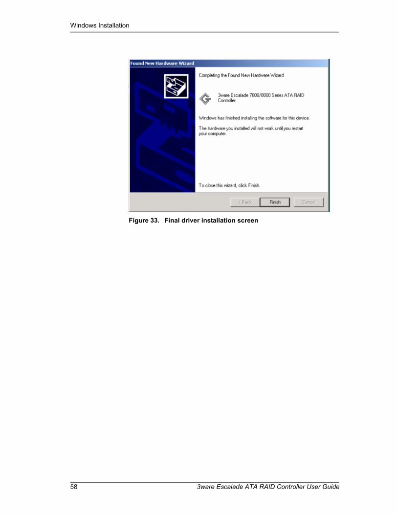
Windows Installation
58 3ware Escalade ATA RAID Controller User Guide
Figure 33. Final driver installation screen
Replacing an existing ATA RAID controller with a new version of the controller
www.3ware.com 59
Remove the existing Escalade ATA RAID Controllerand install the new Escalade ATA RAID Controller
Refer to the Hardware Installation chapter.
Reboot the machine1 Remove the driver diskette from your PC, then install the new ATA RAID
controller. Afterwards, turn your system on.
2 If you choose to reconfigure your disk arrays press Alt-3 to bring up the Disk Array Configuration Utility.
3 Log in as system administrator. When the system has rebooted you should see a brief splash screen, followed immediately by an “Installation Com-plete” notification.
4 Partition and format any new disk arrays or independent disks using Disk Management from Administrative Tools.a Choose Administrative Tools from the Start menu.b Choose Computer Management from the Administrative Tools
menu.c Select Storage.d Select Disk Management.
5 Follow the steps the appear on-screen to write a signature to the drive.
6 Right click on the drive and select Create Volume.
7 Follow the steps the appear on-screen to create a volume and to assign a drive letter.
Install the 3DM disk management utilityRefer to the 3DM Disk Management Utility chapter.

Windows Installation
60 3ware Escalade ATA RAID Controller User Guide

www.3ware.com 61
Linux Installation
Note: If you haven’t yet installed the hardware, return to the 3ware Hardware Installation chapter. The hardware must be installed before you can configure the Escalade ATA RAID Controller.
Red Hat Linux Installation . . . . . . . . . . . . . . . . . . . page 62SuSE Linux Installation . . . . . . . . . . . . . . . . . . . . . page 68
Note: Check 3ware’s web site (www.3ware.com) for the latest release notes and for instructions on how to upgrade your driver and firmware to the latest release. 1. 3ware ships compiled and tested drivers for Red Hat and SuSE Linux. Please refer to our website for the latest compiled drivers. The latest driver source is also bundled with the latest compiled driver on the website, and is in a subdirectory.2. Red Hat and SuSE include 3ware drivers in their distributions. These drivers are often older than what is available on the 3ware website.3. 3ware also releases drivers to open source at www.kernel.org. These drivers are the most recent version, however, these drivers are part of an ongoing evolution of the source code and may not be tested by 3ware for compatibility. If you are using a Linux distribution for which there is not a compiled driver available from 3ware, you can download the source and compile a new driver.
Note: Check your current 3ware driver version number by typing the following command: cat /proc/scsi/3w-xxxx/0*
* Represents controller number(You can also get the driver version from 3DM.)

Linux Installation
62 3ware Escalade ATA RAID Controller User Guide
Red Hat Linux Installation
Note: Release 7.7 of the 3ware code set (including firmware, driver, and 3DM) supports Red Hat versions 8.0 and 9.0
As a Plug and Play device, the Escalade ATA RAID Controller may be con-figured to be your system’s boot device. Or, you can use another device as your boot device, such as a disk attached to the motherboard. Use your sys-tem’s Setup utility to set the boot order according to how you install your operating system.
If you have a new drive configuration without an operating system and want to install Linux on a drive managed by 3ware’s ATA RAID controller, follow the instructions in:
Installing the ATA RAID controller while installing Red Hat Linux (page 62).
If you are installing the ATA RAID controller on a system that already has the operating system installed on a unit connected to another controller, follow the instructions in:
Installing the ATA RAID controller on systems that boot from a different device (page 64).
Note: If you wish to upgrade to a newer 3ware Escalade Linux driver, please refer to the latest Release Notes published on our website at http://www.3ware.com.
Installing the ATA RAID controller while installing Red Hat Linux
Materials required:
■ 3ware CD-ROM (You will be required to create a 3ware Linux Driver Installation Diskette from the files located on the 3ware CD-ROM. Please refer to the “Readme.txt” file on the 3ware CD-ROM for directions.)
■ Red Hat Linux installation CD-ROM and boot disk
Note: We have tested systems where an IDE drive connected to the motherboard interfered with using the Escalade ATA RAID Con-troller as a boot device. Disconnecting the IDE drive while install-ing Linux will eliminate this problem. After Linux is installed, the drive can be reconnected.

Red Hat Linux Installation
www.3ware.com 63
Create disk arraysRefer to the 3ware Hardware Installation and 3ware Disk Array Configuration Utility chapters.
Note: If you want to boot to an array that is larger than 1 TByte, you must use the LILO boot loader in Red Hat versions 8 and 9. The default boot loader (GRUB) will cause the system to hang if you attempt to boot to an array larger than 1 TByte. Earlier ver-sions of Red Hat could not boot to arrays larger than 1 TByte.
Boot with the Red Hat CD-ROM or diskette
Note: The boot diskette is optional since most computers can boot directly from the Red Hat CD-ROM disk.
1 Insert the Red Hat boot diskette into the floppy drive of the computer. If your BIOS supports it you may boot directly from the Red Hat installation CD-ROM instead.
2 When the Welcome to Red Hat display appears type expert at the boot prompt.boot: expert
Install the driver
1 After loading a number of files, you will be asked to insert your driver disk. Insert the 3ware driver installation diskette for Red Hat and press OK. The system automatically reports: Loading 3w-xxxx driver
2 Select the proper language and keyboard types for your locality.
3 If asked for what type of media, select Local CD-ROM since you are installing from CD-ROM.
RAID array initializationRAID 0 arrays do not need to be initialized and are immediately available for use with full performance when created.
RAID 1 and 10 arrays are not initialized when created and are immediately available for use with full performance when created. The first time the array is verified (via the BIOS or 3ware 3DM), the array is initialized. Initialization results in data from one disk (the disk on the lower channel number) being copied to the other drive. In RAID 10 arrays, data from one half of the array is copied to the other half. After the initial verification, subsequent verifies to a

Linux Installation
64 3ware Escalade ATA RAID Controller User Guide
RAID 1 or 10 array result in the data from one drive (or set of drives) being compared to the other drive (or set of drives).
RAID 5 arrays are immediately initialized after being created in the BIOS by writing zeroes to all array members. The user can reboot the system before this is complete in order to use the RAID 5 array immediately. Once booted to the operating system, the RAID 5 array goes into initialization mode after a delay of up to ten minutes. The advantage of this procedure is that the RAID 5 array can be used immediately, but it will not be fault tolerant until the initial-ization is complete. The disadvantage of this is that it takes longer for the array to become fully redundant, because it takes longer to initialize an array than it does to write zeroes to the array.
Install and run 3DM disk management utilityRefer to the 3DM Disk Management Utility chapter. If you are using the 3ware Command Line Interface, refer to the 3ware CLI User Guide.
Installing the ATA RAID controller on systems that boot from a different device
Materials required:■ 3ware CD-ROM
(You will be required to create a 3ware Linux Driver Installation Diskette from the files located on the 3ware CD-ROM. Please refer to the “Readme.txt” file on the 3ware CD-ROM for directions.)
Create disk arraysRefer to the 3ware Hardware Installation and 3ware Disk Array Configuration Utility chapters.
Install the 3ware driver
Note: In the instructions below, <kernel string> refers to the kernel version (i.e., 2.4.2-2 smp) Check 3ware’s website for supported versions.
When you need to type the kernel string, you can press the Tab key to populate the kernel string version (if there is only one), or to list the kernel versions (if there are multiple kernels).
1 Type: mount –t msdos /dev/fd0 /mnt/floppy

Red Hat Linux Installation
www.3ware.com 65
2 For Red Hat 2.4 kernels, type: cp <source> <destination>
For example:cp /mnt/rh80/3w-xxxx.* /lib/modules/<put the kernel string here>/
kernel/drivers/scsi/3w-xxxx.o
When prompted to overwrite, type y.
If you are using Red Hat 9.0, replace rh80 with rh90 in the previous example.
Use the appropriate module name. In the example above, the name of the module you will copy (3w-xxxx.*) varies, depending on the kernel; however you will always copy it to a file named 3w-xxxx.o. The available module files are:
For UP kernels: 3w-xxxx.o
For SMP kernels: 3w-xxxx.smp
For Enterprise kernels: 3w-xxxx.ent
For Bigmem kernels: 3w-xxxx.big
Use the appropriate kernel string. The kernel string will have differ-ent endings, depending on the kernel you are using.
For an SMP kernel (multi-processor), the kernel string will end in smp. For example: 2.4.18-14smp.
For an Enterprise kernel, the kernel string will end in enterprise. For example: 2.4.18-14enterprise
For a Bigmem kernel, the kernel string will end in bigmem. For example: 2.4.18-14bigmem
3 For Red Hat 7.2 and newer, add the following line to /etc/modules.conf, if it isn’t already there: alias scsi_hostadapter 3w-xxxx
4 Run mkinitrd by entering the following:
/sbin/mkinitrd -v -f /boot/initrd-<kernel string1.img> <kernel string1>
Note: The first argument <kernel string1.img> for initrd is the kernel version string. The second argument (<kernel string1>) for initrd is the /lib/modules directory to copy the 3w-xxxx driver from.
5 If you are using the GRUB boot loader, skip to Step 6.

Linux Installation
66 3ware Escalade ATA RAID Controller User Guide
If you are using the LILO boot loader, run LILO to update the boot record on disk by typing the following:/sbin/lilo
The output should be similar to: Added linux *
6 Afterwards, halt the system, add the ATA RAID controller and reboot. During reboot, the new ATA RAID controller should be recognized. Afterwards, the Hardware Discover utility should pop up.
7 Press return to enter the Hardware Discover utility.
8 Select the Configure Device option. The system boot completes and drives are now available.
Compiling the Driver (For experts only)If you wish to compile the driver yourself (for a different kernel version that you are running), then perform the following steps.
Notes: You must have a full Linux kernel source tree in /usr/src/<kernel version> in order to do the compile.
In addition, you must boot to the UP kernel to use the make targets. Otherwise errors will result that will cause the driver build to fail.
1 Download the 3ware driver source from 3ware’s website. (The latest 3ware driver source is bundled with the latest compiled driver and is in the /src sub-directory.)
2 Copy the driver source from the floppy or CD-ROM into a working directory on the Linux system.
3 Untar the driver source with the command, tar zxf 3w-xxxx.tgz.
4 For Red Hat 7.2 and later versions, including Red Hat 8 and 9:
Red Hat 7.2 and later support multiple build targets from makefile.
Note: Boot to UP version of kernel to build all modules except SMP. For SMP, boot to smpkernel.
To build UP module, type:make -f Makefile.rh
The file created is 3w-xxxx.o
To build SMP module, type:

Red Hat Linux Installation
www.3ware.com 67
make smp -f Makefile.rh
The file created is 3w-xxxx.smp
To build Enterprise module, type:make ent -f Makefile.rh
The file created is 3w-xxxx.ent
To build Bigmem module, type:
(This is for when you have more than 4 GBytes of system RAM and you are using the BigMem kernel.)make big -f Makefile.rh
The file created is 3w-xxxx.big
To build Boot module
(this is used when creating a driver for the boot diskette), type: make bot -f Makefile.rh
The file created is 3w-xxxx.bot
5 Copy the module as follows:
For 2.4 kernels, copy module to:
/lib/modules/<kernel string>/kernel/drivers/scsi/3w-xxxx.o
RAID array initializationRAID 0 arrays do not need to be initialized and are immediately available for use with full performance when created.
RAID 1 and 10 arrays are not initialized when created and are immediately available for use with full performance when created. The first time the array is verified (via the BIOS or 3ware 3DM), the array is initialized. Initialization results in data from one disk (the disk on the lower channel number) being copied to the other drive. In RAID 10 arrays, data from one half of the array is copied to the other half. After the initial verification, subsequent verifies to a RAID 1 or 10 array result in the data from one drive (or set of drives) being compared to the other drive (or set of drives).
RAID 5 arrays are immediately initialized after being created in the BIOS by writing zeroes to all array members. The user can reboot the system before this is complete in order to use the RAID 5 array immediately. Once booted to the operating system, the RAID 5 array goes into initialization mode after a delay of up to ten minutes. The advantage of this procedure is that the RAID 5 array can be used immediately, but it will not be fault tolerant until the initial-ization is complete. The disadvantage of this is that it takes longer for the array to become fully redundant, because it takes longer to initialize an array than it does to write zeroes to the array.

Linux Installation
68 3ware Escalade ATA RAID Controller User Guide
Install and run 3DM disk management utilityRefer to the 3DM Disk Management Utility chapter. If you are using the 3ware Command Line Interface, refer to the 3ware CLI User Guide.
SuSE Linux Installation
Note: Release 7.7 of the 3ware code set (including firmware, driver, and 3DM) supports SuSE versions 8.1 and 8.2
As a Plug and Play device, the Escalade ATA RAID Controller may be configured to be your system’s boot device or you can use another device, such as a disk attached to the motherboard as your boot device. Use your system’s Setup utility to set the boot order according to how you install your operating system.
If you have a new drive configuration without an operating system and want to install Linux on a drive managed by 3ware’s ATA RAID controller, follow the instructions in:
Installing the ATA RAID controller while installing SuSE Linux with YaST2 (page 68).
If you are installing the ATA RAID controller on a system that already has the operating system installed on a unit connected to another controller, follow the instructions in:
Installing the ATA RAID controller on systems that boot from a different device (page 70).
Note: If you wish to upgrade to a newer 3ware Escalade Linux driver, please refer to the latest Release Notes published on our website at http://www.3ware.com.
Installing the ATA RAID controller while installing SuSE Linux with YaST2
Materials required■ 3ware CD-ROM
(You will be required to create a 3ware Linux Driver Installation Diskette from the files located on the 3ware CD-ROM. Please refer to the “Readme.txt” file on the 3ware CD-ROM for directions.)
SuSE Linux Installation
www.3ware.com 69
■ SuSE Linux Installation CD-ROM/DVD
Note: We have tested systems where an IDE drive connected to the motherboard interfered with using the Escalade ATA RAID Con-troller as a boot device. Disconnecting the IDE drive while install-ing Linux will eliminate this problem. After Linux is installed, the drive can be reconnected.
Create disk arraysRefer to the 3ware Hardware Installation and 3ware Disk Array Configuration Utility chapters.
Boot with the SuSE CD/DVD
1 Boot directly from the SuSE installation CD #1 or DVD.
2 When installing SuSE 8.1, depress the Alt key when the main installation menu is displayed. You will then be prompted to insert the driver disk.
When installing SuSE 8.2, depress the F3 key when the main instal-lation menu is displayed. You will then be prompted to insert the driver disk.
3 Insert the 3ware Linux driver installation diskette.
4 Click OK and finish the installation.
Note: If you receive a message about the controller timing out and resetting while installing on an SMP system, you will need to per-form the installation using the Installation - Safe Mode option.
RAID array initializationRAID 0 arrays do not need to be initialized and are immediately available for use with full performance when created.
RAID 1 and 10 arrays are not initialized when created and are immediately available for use with full performance when created. The first time the array is verified (via the BIOS or 3ware 3DM), the array is initialized. Initialization results in data from one disk (the disk on the lower channel number) being copied to the other drive. In RAID 10 arrays, data from one half of the array is copied to the other half. After the initial verification, subsequent verifies to a RAID 1 or 10 array result in the data from one drive (or set of drives) being compared to the other drive (or set of drives).
RAID 5 arrays are immediately initialized after being created in the BIOS by writing zeroes to all array members. The user can reboot the system before

Linux Installation
70 3ware Escalade ATA RAID Controller User Guide
this is complete in order to use the RAID 5 array immediately. Once booted to the operating system, the RAID 5 array goes into initialization mode after a delay of up to ten minutes. The advantage of this procedure is that the RAID 5 array can be used immediately, but it will not be fault tolerant until the initial-ization is complete. The disadvantage of this is that it takes longer for the array to become fully redundant, because it takes longer to initialize an array than it does to write zeroes to the array.
Install and run 3DM disk management utilityRefer to the 3DM Disk Management Utility chapter. If you are using the 3ware Command Line Interface, refer to the 3ware CLI User Guide.
Installing the ATA RAID controller on systems that boot from a different device
Materials required:■ 3ware CD-ROM
(You will be required to create a 3ware Linux Driver Installation Diskette from the files located on the 3ware CD-ROM. Please refer to the “Readme.txt” file on the 3ware CD-ROM for directions.)
Create disk arraysRefer to the 3ware Hardware Installation and 3ware Disk Array Configuration Utility chapters.
Install the 3ware driver
Notes: In the instructions below:<kernel string> refers to the kernel version (i.e. 2.4.18-4GB, etc.) Check 3ware’s website for supported versions.
1 Edit /etc/sysconfig/kernel and make sure the file contains the following line: INITRD_MODULES=”3w-xxxx”

SuSE Linux Installation
www.3ware.com 71
Note: Other modules may be listed before or after 3w-xxxx, depending on the installation. You may see entries like reiserfs, ext3 or scsi_mod. If present, leave them, since the system needs them to boot properly.
2 Mount the floppy drive and copy the driver into a working directory.mount –t msdos /dev/fd0 /floppycp /mnt/linux/suse/i386-<kernel string>/modules/3w-xxxx.o to /
lib/modules/<kernel string>/kernel/drivers/scsi/3w-xxxx.o
/sbin/insmod /lib/modules/<kernel string>/kernel/drivers/scsi/3w-xxxx.o
umount /floppy
3 mk_initrd
4 If you are using the GRUB boot loader, you are finished.
If you are using the LILO boot loader, run LILO to update the boot record on disk by typing the following:/sbin/lilo
The output should be similar to: Added linux *
Compiling the Driver (For experts only)If you wish to compile the driver yourself (for a different kernel version that you are running), then perform the following steps.
1 Copy the driver source from the floppy into a working directory.
2 Untar the driver source with the command, tar zxfp 3w-xxxx.tgz.
3 You must have a full Linux kernel source tree in /usr/src/linux in order to do the compile.
4 To build UP module boot to desired UP kernel, type:make -f makefile.oth
The created file is 3w-xxxx.o
5 To build SMP module boot to desired SMP kernel, type:make smp -f makefile.oth
The created file is 3w-xxxx.smp
6 Copy the module to the scsi directory.
For 2.4 kernels, copy module to:/lib/modules/<kernel string>/kernel/drivers/scsi/3w-xxxx.o

Linux Installation
72 3ware Escalade ATA RAID Controller User Guide
Install and run 3DM disk management utilityRefer to the 3DM Disk Management Utility chapter. If you are using the 3ware Command Line Interface, refer to the 3ware CLI User Guide.

www.3ware.com 73
FreeBSD Installation
Note: Installing FreeBSD on a system with an old driver can cause a system to become unstable. For additional information, see the Release Notes on the 3ware website, and the Knowledgebase in the Support section of the 3ware website at http://www.3ware.com.
Note: The instructions in this chapter assume that you have already installed the 3ware Escalade controller and configured your disk arrays. If you have not yet done so, follow the instructions in the 3ware Hardware Installation chapter and the 3ware Disk Array Configuration Utility chapter.
A drive or array managed by the 3ware Escalade controller may be configured to be your system’s boot device. Or, you can use another device as your boot device, such as a disk attached to the motherboard.
This chapter provides step-by-step instructions for both situations:
■ Installing the 3ware driver and FreeBSD on a new drive or array (page 74).
■ Installing the 3ware driver on a system that boots FreeBSD from a different device (page 75).
You will also find instructions for compiling the 3ware driver from the source files.
Note: 3DM does not work under FreeBSD, however you can use the 3ware CLI (Command Line Interface), available from the 3ware website at http://www.3ware.com/support/download.asp.

FreeBSD Installation
74 3ware Escalade ATA RAID Controller User Guide
Installing the ATA RAID controller while installing FreeBSD
Materials required:■ 3ware Escalade driver. Check your 3ware CD-ROM for the FreeBSD
folder freebsd/drivers/src and locate the file twe.tgz. You can also down-load the FreeBSD driver from the 3ware web site (http://www.3ware.com).
■ FreeBSD installation CD-ROM or diskette.
Create disk arraysRefer to the 3ware Hardware Installation and 3ware Disk Array Configuration Utility chapters.
Note: Some versions of FreeBSD cannot boot to arrays larger than 1 TByte. If you want to create an array larger than 1 TByte, check to make sure that the version of FreeBSD you have supports it.
Boot with the FreeBSD CD-ROM or diskette
Note: The boot diskette is optional since most computers can boot directly from the FreeBSD CD-ROM disk.
For FreeBSD Version 4.8:
The FreeBSD 4.8 GENERIC kernel already has a statically-built old 3ware driver. This driver needs to be replaced. The steps below describe this process. After you install FreeBSD, you will replace the old 3ware driver source files with the current ones and then rebuild the kernel.
1 Run the FreeBSD installation and reboot.
For instructions on how to install FreeBSD, see the FreeBSD website, at http://www.freebsd.org/
2 Copy the 3ware driver source file archive (twe.tgz) to an accessible location.
3 Unpack the 3ware driver source files.
4 Backup the files in these directories:/sys/dev/twe /sys/modules/twe
5 Copy all the source files (*.c *.h) to /sys/dev/twe.

www.3ware.com 75
6 Copy the Makefile to /sys/modules/twe.
7 Rebuild the kernel. (Refer to the FreeBSD documentation for how to rebuild the kernel.)
8 Install the new kernel
9 Reboot with the new kernel.
RAID array initializationRAID 0 arrays do not need to be initialized and are immediately available for use with full performance when created.
RAID 1 and 10 arrays are not initialized when created and are immediately available for use with full performance when created. The first time the array is verified (via the BIOS or 3ware 3DM), the array is initialized. Initialization results in data from one disk (the disk on the lower channel number) being copied to the other drive. In RAID 10 arrays, data from one half of the array is copied to the other half. After the initial verification, subsequent verifies to a RAID 1 or 10 array result in the data from one drive (or set of drives) being compared to the other drive (or set of drives).
RAID 5 arrays are immediately initialized after being created in the BIOS by writing zeroes to all array members. The user can reboot the system before this is complete in order to use the RAID 5 array immediately. Once booted to the operating system, the RAID 5 array goes into initialization mode after a delay of up to ten minutes. The advantage of this procedure is that the RAID 5 array can be used immediately, but it will not be fault tolerant until the initial-ization is complete. The disadvantage of this is that it takes longer for the array to become fully redundant, because it takes longer to initialize an array than it does to write zeroes to the array.
Installing the ATA RAID controller on systems that boot from a different device
Materials required:■ 3ware Escalade driver. Check your 3ware CD-ROM for a FreeBSD
folder. If you do not find one, download the FreeBSD driver from the 3ware web site (http://www.3ware.com).
The driver file is named twe.ko.

FreeBSD Installation
76 3ware Escalade ATA RAID Controller User Guide
To install the 3ware driver
For FreeBSD Version 4.8:
The FreeBSD kernel already has an old 3ware driver embedded. You cannot load the new driver on top of the existing driver, so you must first remove it.
1 Make sure the FreeBSD driver is in an accessible location.
2 Remove the old 3ware driver which is part of the kernel.
Change to this directory:/usr/src/sys/i386/conf
Copy the configuration file to a custom file. For example, if the configuration file is GENERIC, type:cp GENERIC CUSTOM
Edit the custom filevi CUSTOM
Comment out the line under RAID controllers that says#device twe # 3ware Escalade
(move to that line and type #)
Save the file.
Follow FreeBSD instructions to rebuild the kernel and install the new kernel.
3 Reboot with the rebuilt kernel.
4 Back up /modules/twe.ko
5 Copy the driver file (twe.ko) to /modulescp twe.ko /modules
6 Load the driverkldload twe.ko
If units are present, you should see unit information in the system log (usually, /var/log/messages).
To make the driver part of the kernel
1 Copy the 3ware driver source file archive (twe.tgz) to an accessible location.
2 Unpack the 3ware driver source files.
3 Back up the original source files under /sys/dev/twe and /sys/modules/twe
4 Copy the new source files (*.c *.h) to /sys/dev/twe

www.3ware.com 77
5 Copy the new Makefile to /sys/modules/twe
6 Rebuild the kernel and install the new kernel.
7 Reboot with the rebuilt kernel.
If you are using the 3ware Command Line Interface, refer to the CLI documentation.
Compiling the Driver (For experts only)If you wish to build the driver yourself (for a different kernel version that you are running), then perform the following steps.
1 Copy the 3ware driver source file archive (twe.tgz) to an accessible location.
2 Unpack the 3ware driver source files.
3 Back up the original source files under /sys/dev/twe and /sys/modules/twe
4 Copy the Makefile to /sys/modules/twe
5 Change the directory to /sys/modules/twe
6 Build the drivermake cleanmake
7 Back up /modules/twe.ko
8 Copy the driver to the /modules directory.cp twe.ko /modules/twe.ko
9 Unload the existing driver, if anykldunload twe.ko
10 Load the new driver.kldload twe.ko

FreeBSD Installation
78 3ware Escalade ATA RAID Controller User Guide

www.3ware.com 79
3DM Disk Management Utility
The 3DM disk management utility, allows you to view status and version information about your Escalade ATA RAID Controller. 3DM alerts you when a disk array needs maintenance and you can maintain your disk arrays from 3DM. You can add or remove drives, specify an available drive as a hot spare or launch the rebuild process. Array status can be viewed or arrays can be maintained remotely via a standard web browser provided you have access to the network containing the Escalade ATA RAID Controller.
Event notification occurs from 3DM when the ATA RAID controller requires attention, such as when a disk array becomes degraded and is no longer fault tolerant. Event notification will only occur while 3DM is running, so we rec-ommend that 3DM be left running as a background utility on the ATA RAID controller’s machine. Event notification’s e-mail feature can send an e-mail to a specified recipient when there is a problem with the array. The e-mail that the recipient receives will include most of the information that is provided in the Logs on the Alarms page.
Note: 3DM does not work under FreeBSD. If you are using FreeBSD, use the 3ware CLI (command line interface) available from the 3ware website at http://www.3ware.com/support/download.asp.
Refer to the following sections for more information:Windows Installation . . . . . . . . . . . . . . . . . . . . . . . page 80Linux Installation . . . . . . . . . . . . . . . . . . . . . . . . . . page 81Checking Array Status . . . . . . . . . . . . . . . . . . . . . . page 84Password Setup . . . . . . . . . . . . . . . . . . . . . . . . . . . page 89Selecting I/O and Rebuild Speed. . . . . . . . . . . . . . page 91Mirrored Array Maintenance . . . . . . . . . . . . . . . . . page 92

3DM Disk Management Utility
80 3ware Escalade ATA RAID Controller User Guide
Windows Installation
Installing 3DM for Windows 2000/XP/20031 Insert the 3DM installation media into the CD-ROM.
2 Run the 3DMsetup.exe program found on the installation disk. You may do this using Windows Explorer by double-clicking on the Setup file found on the installation disk or by executing run d:\windows\3dm\3dmsetup.exe from the Run... in the Start menu.
3 The 3DM Setup Standard install window will guide you through the installation process.
4 At the Remote Monitoring and Security Configuration window (see Figure 34), check the first checkbox to change the HTTP port that you would like 3DM to use. If you do not know what port to use, leave the box unchecked and use the default port. If choose to change the HTTP port and enter port 0, the web interface will be disabled (not recommended). If the second checkbox is checked, only localhost connections are allowed (Internet and Intranet connections are not allowed). Uncheck the second checkbox if Internet and Intranet connections are desired.
Figure 34. 3DM Remote Monitoring and Security Configuration Display
5 At the E-mail Notification Preferences window (see Figure 35) enter the e-mail address of the user who will be receiving the 3DM e-mail status messages. You may enter multiple e-mail addresses, separating each entry with a comma (,). If you do not know your server name, ask your system

Linux Installation
www.3ware.com 81
administrator or check the e-mail preferences or setup options on your e-mail client.
Figure 35. 3DM E-mail Notification Preferences
6 Continue with the installation as prompted. 3DM gives you the option of starting the application and opening the browser window when you complete the installation (recommended). You can run 3DM later by selecting 3DM from the Start menu. To view 3DM remotely via a standard web browser, enter the URL of the system containing the Escalade ATA RAID Controller in the address line of your browser. The default URL is http://localhost:1080/.
Linux Installation
Installing 3DM for Red Hat Linux or SuSE Linux 1 Insert the 3ware software installation CD-ROM for Linux into the CD-
ROM drive.
2 Mount the CD-ROM disk:mount /dev/cdrom
Note: For older Red Hat systems, type:mount -t iso9660 /dev/cdrom /mnt/cdromFor older SuSE systems, type:mount -t iso9660 /dev/cdrom /cdrom

3DM Disk Management Utility
82 3ware Escalade ATA RAID Controller User Guide
3 Change the directory and run the install script:
For Red Hat Linux:cd /mnt/cdrom/linux/3dm./install.3dm
For SuSE Linux:cd /cdrom/linux/3dm./install.3dm
You will be prompted with the a series of questions to complete the installation.
4 The first question asks if RPM was used to install the Escalade driver and/or 3DM. The default answer is no.
5 The second question asks for the location of the help documentation:Please enter the location of the help documentation (default is /usr/local/doc/3dm)
6 The next question asks if you would like to receive an e-mail message when an event occurs. The default to this question is “yes”. If you enable e-mail notification you will be asked to provide the name of the mail server, the user name for the person who will send the E-mail notification (typically the local host name) and the user name for the person who will receive the e-mail notification (typically the system administrator). To enter multiple e-mail addresses, each address must be separated by a comma:Would you like to have e-mail notification enabled (Y/N)?Please enter the name of your mail server: (default is local host name)Please enter the name of the user you want sending e-mail notification: (default is root)Please enter the name of the user you want receiving e-mail notification: (default is 3ware_admin)
7 The next question asks for the HTTP port that you would like 3DM to use. If you do not know what port to use, select the default:Please enter the port number you would like to use for web monitoring (default is 1080)
8 The next question asks if you want to limit 3DM connections to the local machine:Would you like 3DM connection security to limit connections to localhost only? (default is yes)
9 Change the directory and then eject the CD-ROM disk when finished:cd /homeeject cdrom

Linux Installation
www.3ware.com 83
Starting 3DM3DM should start automatically after installation and upon bootup. If you need to start 3DM manually, follow these steps:
1 Login as root.
2 Afterwards, type:
For Red Hat Linux:/etc/rc.d/init.d/3dm start
For SuSE Linux:/etc/rc.d/3dm start
Uninstalling 3DMTo uninstall 3DM for Linux, follow these steps:
1 Insert the 3ware software installation CD-ROM for Linux into the CD-ROM drive.
2 Mount the CD-ROM disk:mount /dev/cdrom
Note: For older Red Hat systems, type:mount -f iso9660 /dev/cdrom /mnt/cdromFor older SuSE systems, type:mount -f iso9660 /dev/cdrom /cdrom
3 Change the directory and run the uninstall script:cd /mnt/cdrom/linux/3dm or /cdrom/linux/3dm./install.3dm --u
4 Eject the CD-ROM disk when finished:cd /homeeject cdrom
Note: If 3DM Linux is reinstalled or restarted, close any open web browsers before starting 3DM again to close the server socket.

3DM Disk Management Utility
84 3ware Escalade ATA RAID Controller User Guide
Checking Array StatusArray status can be viewed using a web browser. Event notification occurs when the ATA RAID controller requires attention, such as when a disk array becomes degraded and is no longer fault tolerant. Event notification will only occur while 3DM is running. Therefore, 3ware recommends that 3DM be left running as background utility on the ATA RAID controller’s machine. Event notification’s e-mail feature can send an e-mail to a specified recipient when there is a problem with the array.
Note: The format and style of the 3DM browser windows illus-trated in this chapter are examples only. The actual “look” of the windows will depend on the browser, 3DM version and operating system in use.
View status using your standard browserOpen the 3DM browser window (see Figure 36) by starting your standard web browser and entering the URL of the system where 3DM is running in the address bar of your browser. The default URL is http://localhost:1080/ or http://127.0.0.1:1080/.
Note: For security reasons, Mozilla does not allow connections to certain ports including port-1080. To override this on a per-port basis, the Mozilla release notes recommend to add a comma-sepa-rated list of ports to default/all.js (in your Mozilla installation directory). For example, to unblock port 1080, use the following line:pref(“network.security.ports.banned.override”, “1080”)
This file is located at: /usr/lib/mozilla/defaults/pref/all.js
Disk arrays and independent disks are listed on the 3DM Home display. Disks that are members of an array are indented and listed below their parent array. The type and size of the disks or arrays are listed as well as status of each array, as shown in Figure 36. For arrays undergoing rebuilds, the rebuild sta-tus for each drive and port is displayed.

Checking Array Status
www.3ware.com 85
Figure 36. 3DM Home Display
The Details display (see Figure 37) gives ATA RAID controller version and status information in text format, which is helpful when contacting 3ware Customer Support with questions or for troubleshooting. Its text format allows you to select the text in the window with your mouse and use the sys-tem clipboard to cut and paste it into e-mail or documentation.
The Details display (see Figure 37) gives the following detailed information on the 3ware disk I/O subsystem:
■ The hostname is displayed. This is the name that is typed into the web browser, along with the specified port, to bring up 3ware 3DM (e.g. http://<hostname>:1080)
■ The number of 3ware ATA RAID controllers in the system is also dis-played, as well as the current version of the operating system including service level and any service packs that are installed.
■ Detailed information for each controller is displayed, such as its model number, serial number, firmware and BIOS versions, unit count (total number of disk arrays on the controller), and version numbers of the chips on the 3ware card.
■ Information is displayed on each unit (a unit is a disk array or JBOD). The array status, capacity, write cache status, RAID type, and subunits in the array are displayed.
■ Information is displayed on each subunit (a subunit is a drive used in a particular array). The individual drive status for each drive is displayed.

3DM Disk Management Utility
86 3ware Escalade ATA RAID Controller User Guide
■ Under drive count is displayed. Detailed information on the individual disk drives, such as disk drive status, disk drive capacity, model number, and serial number.
Figure 37. 3DM Details Display
Before sending an e-mail or calling 3ware Customer Service, it is a good idea to take a snapshot of the Details display so that you can respond to questions about your system configuration to the Customer Support representative.
The Monitor display (see Figure 38) is useful for overall visual status of your disk arrays. The Monitor display opens with either a green (all OK), yellow (during array initialization or rebuild), or red (error alarm) banner. A monitor window may be opened for each system if you have multiple systems to mon-itor. Status for all systems can be checked at a glance by minimizing each Monitor display, leaving the status color indication visible.

Checking Array Status
www.3ware.com 87
Figure 38. 3DM Monitor Display
The Alarms display (see Figure 39) keeps a log of all alarms, also called Automatic Event Notifications (AENs), that have occurred on the disk arrays. An alarm occurs when the ATA RAID controller requires attention, such as when a disk array becomes degraded and is no longer fault tolerant. SMART notifications appear in this display. Alarm messages are categorized by the following levels of severity:
■ Errors, shown next to a red box
■ Warnings, shown next to a yellow box
■ Information, shown next to a blue box
The Download Error Log button allows you to save the alarm messages and SMART data to disk. If necessary, the saved file can be shipped to 3ware Cus-tomer Support for troubleshooting assistance. A button is also provided to erase the logged data. The SMART data is displayed in hex format and may appear to be garbled if displayed on an ASCII text editor. To read the SMART data, use a program that can display hex data.
The Extended Error Log is a text file that records AEN information along with the AEN’s severity. If the severity of the AEN is of “Error” level, a cap-ture of the Download Error Log is also provided in the Extended Error Log. The location of the Extended Error Log text file is listed at the bottom of the Alarms page.

3DM Disk Management Utility
88 3ware Escalade ATA RAID Controller User Guide
Note: The controller number is automatically assigned by Win-dows. Controllers 0 and 1 are typically the on-board motherboard ATA controllers. If the next controller in the system is a 3ware con-troller, it would be assigned to controller 2. Subsequent controllers would be 3, 4, etc. A SCSI card from another manufacturer would also be assigned a controller number.
Note: The time displayed for each event on the Alarms page may differ slightly from the times listed on the Alarms pop-up notifica-tion.
Figure 39. 3DM Alarms Display
The Settings display (see Figure 40) allows you to configure 3DM’s email notification, password, background task rate and cache settings.

Checking Array Status
www.3ware.com 89
Figure 40. 3DM Settings Display
Password setup3DM now provides different access levels for users and administrators. If password protection is enabled, a password must be entered into the login dis-play shown in Figure 41 and Figure 42. The Administrator access level allows the user to fully configure 3DM. The User access level allows the user to view pages within 3DM. These passwords work independently of each other.
If the Administrator password is enabled, 3DM prompts the user for a pass-word if a change in the configuration is attempted on either the settings, alarm, or the configuration pages. If the User password is enabled, 3DM only prompts the user for a password when the browser session is started. The default password for both the User and Administrator is “3ware”.
Passwords are case sensitive. The password setup procedure is as follows:
Note: Do not select the Enable box in the 3DM Settings display before performing these steps.

3DM Disk Management Utility
90 3ware Escalade ATA RAID Controller User Guide
1 Enter the current password in the current password box of the 3DM Set-tings display (see Figure 40).
Note: If password protection is being configured for the first time, enter the factory-set default password “3ware” in the box.
2 Enter the new password in the new password box and again in the confirm box.
3 Press the Change Password button to enable password protection. To enable password protection, refer to “Enable/disable password protection” on page 91
Figure 41. 3DM Administrator Login Display
Note: If you forget your password, you can reset the password to 3ware by uninstalling 3DM and then reinstalling it.

Checking Array Status
www.3ware.com 91
Figure 42. 3DM User Login Display
Enable/disable password protectionWith the 3DM password utility enabled, using 3DM will require entering the password into the login display shown in Figure 41. To enable password pro-tection, be sure to perform the setup procedure on page 89, then select the Enabled option in the Password Setup portion of the 3DM Settings display (see Figure 40). To disable the utility, you must log in as an Administrator before you are permitted to select the Disabled option in the Settings win-dow. If both Administrator and User Passwords are enabled, you are prompted for both the User and Administrator passwords.
Selecting background task rateBackground Task Rate allows a user to set the relative performance of nor-mal IO and background tasks.
Selecting remote accessRemote Access, if enabled, allows a remote machine to connect to 3DM. If this option is disabled and a user attempts to connect to 3DM remotely an error message will be displayed. This setting defaults to “Disabled”.
Selecting cache optionsThe 3DM Settings display provides a selection for enabling or disabling the drive’s write cache. See “Select write cache properties” on page 34 for more information.

3DM Disk Management Utility
92 3ware Escalade ATA RAID Controller User Guide
Event notification via e-mailIf an event occurs, an event notification will be e-mailed to the recipient iden-tified in the e-mail setting specified at 3DM installation. The e-mail will con-tain the same information found on the Alarm display.
Configuration and Array Maintenance Settings
From the 3DM Configure Display (see Figure 43), you can designate an available drive as a hot spare, schedule rebuilds and media scans, or remove and add a drive as part of a hot swap procedure.
Figure 43. 3DM Configure Display

Configuration and Array Maintenance Settings
www.3ware.com 93
Specifying a hot spareEscalade ATA RAID Controllers give you the option to specify a hot spare from one of your available ports (currently shown as offline). Hot spares should be selected after mirror or RAID 5 creation. Refer to Creating a disk array in the 3ware Disk Array Configuration Utility chapter. To specify a hot spare after the system is booted, physically add the spare drive and click on the check box next to the available offline port; then click on the Add Spare button.
Note: Hot spare drives must be equal to or larger than the drives used for the redundant array.
Auto rebuild of a redundant arrayIf a hot spare is specified and the array degrades, an event notification is gen-erated and the hot spare dynamically replaces the failed drive in a redundant array without user intervention. Rebuild will automatically be launched as background process and an event notification will notify the user when the rebuild process is complete (if 3DM is running and e-mail notification is setup).
Rebuilding a redundant array with a hot swap driveHot swap allows a user to replace a failed drive in a redundant array while the system remains up. Hot swap can be used when 24x7 system operation is a consideration. If multiple drives are faulted in a RAID 10 configuration, the drives are rebuilt sequentially starting with the lowest port number.
1 Click on the check box of the failed drive.
2 Click the Remove Drive button.
3 Physically remove the failed drive and replace it with a new drive.
4 Click on the check box of the new drive.
5 Click the Add Drive button.
6 Click on the check boxes of at least two members of the array to be rebuilt. This should include the new drive added in step 3.
7 Click the Rebuild Array button. The rebuild process will run in the background and an event notification will be sent when it is completed.
Selecting Force Continue on Source ErrorsSelecting the Force Continue on Source Errors check box prior to rebuild-ing the array ensures rebuilds are not terminated if ECC errors are detected on

3DM Disk Management Utility
94 3ware Escalade ATA RAID Controller User Guide
the source disk. Uncorrectable blocks will be rewritten, but the data may be incorrect. It is recommended that a file system check is executed when the rebuild completes. By default, this function is disabled. Select this option only if the initial rebuild has failed because of an ECC error on the source disk. The reason that a rebuild failed is posted in the Alarms page of 3DM.
Scheduling background tasksThe 3DM Configuration display allows routine maintenance of storage media by scheduling array rebuilds, initialization, array verifications and media scans. The background tasks selected are only performed during the scheduled time. Depending on the schedule and system workload, back-ground tasks may require more than one scheduled duration to complete. The day of the week (or daily) time and duration to perform the selected back-ground tasks can be specified using the pull-down menus. When finished, be sure to click on the Save Schedule button to confirm the entries.
Background Task FeaturesSelecting the Rebuild/Initialize feature forces rebuilds and initialization to be performed only during the time specified by the schedule. If this feature is not selected, rebuilds and initialization can operate anytime they are required. This feature affects only redundant arrays (RAID 1, 5 and 10).
The Verify feature verifies the redundancy of all RAID 1, 5 and 10 arrays.
The Media Scan feature continuously scans all drives (including hot-spares) for media errors.
Note: Rebuild/Initialize operations preempt Verify and Media Scan operations. If a rebuild or initialization is required, it will be per-formed before Verify and Media Scan during the scheduled win-dow. Tasks cannot be performed in time increments of less than one hour. For example, if both Verify and Media Scan are selected and the scheduled window is five hours, the verify operation is per-formed during the first three hours and the media scan follows dur-ing the remaining two hours.
Examples of Background Task PrioritiesThe following examples assume the scheduled duration is four hours.
■ Only Verify is selected: The verification operation is performed during the scheduled window. If the operation completes with time remaining in the window, the operation begins again on the same array (if there is only one array) or continues on to additional redundant arrays. The verify opera-tion stops when the duration in the scheduled window completes.

Configuration and Array Maintenance Settings
www.3ware.com 95
■ Only Media Scan is selected: The media scan operation scans each drive starting at the lowest port. If all the drives have been scanned and there is time remaining, the operation begins scanning the lowest port again and continues until the scheduled time completes.
■ Verify and Media Scan are selected: Both tasks run sequentially within the scheduled window. If the scheduled duration is four hours, the verifica-tion operation is run during the first two hours and the media scan opera-tion follows during the remaining two hours. If the duration is only one hour, only the verification operation is performed.
■ Rebuild/Initialize, Verify, and Media Scan are selected: If all three opera-tions are selected and a rebuild/initialize operation is required, the rebuild/initialize operation is performed first. If this operation completes within the first two hours of the window, a verification operation starts. If the rebuild/initialize operation completes in the last two hours of the win-dow, the media scan operation starts.
The Help display (see Figure 44) provides direct links to 3ware’s website and online help documents.
Figure 44. 3DM Help Display

3DM Disk Management Utility
96 3ware Escalade ATA RAID Controller User Guide

Troubleshooting: Problems and Solutions
Note: For more assistance troubleshooting problems, see the FAQ and knowledgebase areas of 3ware’s website:
http://www.3ware.com/support.http://www.3ware.com/NewFaq/3ware.htm.http://www.3ware.comKB/kb.asp
Hardware installationQ1: The rail on the ATA RAID controller doesn't fit in the case.
Use a screwdriver to remove the black end rail. It aligns and secures the ATA RAID controller in the computer chassis but is not critical for oper-ation.
Q2: The system doesn’t begin booting (no BIOS runs) when the ATA RAID controller is installed but boots OK when the con-troller is removed.Check the cabling between the drives and the ATA RAID controller. A cable plugged in upside down can prevent your system from running its BIOS.
Q3: The 3ware BIOS screen never appears.The ATA RAID controller is not installed properly. Reinstall the hard-ware and reboot. There may also be a problem with the motherboard. Please check the Motherboard Compatibility List on the 3ware website at http://www.3ware.com/products/compatibility.asp to see if you moth-erboard has been tested by 3ware.
www.3ware.com 97

Troubleshooting: Problems and Solutions
Q4: Some of the drives do not appear in the Disk Array Configu-ration Utility’s main display.Your drives are not connected properly to the ATA RAID controller. Check that both the power and ATA cables are connected properly and that the drives are all properly jumpered. To operate properly the ATA RAID controller requires that drives be set as Single (if available on your drive) or Master.
Q5: I am using a Dell Dimension system that locks-up when booting after a 3ware card is installed. What is going on?This symptom is caused by a Dell BIOS bug. Basically, this bug sees the system boot drive as two primary master drives. That causes the system to hang. Enter the Dell BIOS setup and reload the BIOS defaults.
Software installationQ6: The ATA RAID controller was configured without problems,
but the system does not boot.The problem could be one or more of the following:■ The operating system is installed on a device that is not in your sys-
tem’s boot order. Use your system’s Setup utility to include the Stor-Switch controller in the boot order.
■ If your operating system was installed before you configured your disk arrays, you may have overwritten your operating system. Remember that creating or deleting a disk array overwrites any exist-ing data on the member drives. Reinstall your operating system.
■ If you installed your operating system when you installed the ATA RAID controller, you may have made a mistake in installing the oper-ating system. Reinstall your operating system.
Q7: An array shows up as incomplete in the Disk Array Configu-ration Utility’s main display similar to the following:
Array Unit 1 - Incomplete 6.5 GB Port 1 - FUJITSU MPC3065AH 6.5 GB
The array has some but not all of its members available. The array will be unusable. If this array is your boot device, your machine will not boot. You must either find the missing disk and replace it to complete the array, or release the member disks by deleting the incomplete array(s) listed in the display. Remember that deleting a disk array over-writes any existing data on the member drives.
Q8: The use of Red Hat’s Disk Druid partitioning utility with Red Hat 6.2 or 7.0 is limited to 112 GB. Use fdisk if more storage capacity is required.
98 3ware Escalade ATA RAID Controller User Guide

Screen display messages
Q9: My driver fails to boot.There is most likely a compatibility problem between the motherboard system BIOS and the 3ware BIOS. Check the 3ware website to see if your motherboard is compatible with the 3ware BIOS, and check with your motherboard manufacturer for potential BIOS updates.
Screen display messagesFigure 45 through Figure 50 are screen messages that might appear during installation. The AEN (asynchronous error notification) messages shown in Table 1 on page 100 appear when a hardware or software related problem has been detected after the ATA RAID controller has been installed and made operational. Descriptions of each AEN are provided after the table.
Figure 45. Installation or Removal Dialog Box
Figure 46. A Warning for All Software Removal Requests
Figure 47. Confirmation of Successful Software Removal
Figure 48. Administrator Privileges Required Warning
www.3ware.com 99

Troubleshooting: Problems and Solutions
Figure 49. Firmware Upgrade Requirement Warning
Figure 50. System Reboot Request
AEN MessagesThe AEN messages issued by the ATA RAID controller when an error is detected are summarized in the table below. Descriptions of each are provided at the end of the table.
Table 1: AEN Error Messages
Message Value
AEN_SOFT_RESET 001h
AEN_DEGRADED_UNIT 002h
AEN_CONTROLLER_ERROR 003h
AEN_REBUILD_FAIL 004h
AEN_REBUILD_DONE 005h
AEN_INCOMP_UNIT 006h
AEN_INIT_DONE 007h
AEN_UNCLEAN_SHUTDOWN 008h
AEN_APORT_TIMEOUT 009h
AEN_DRIVE_ERROR 00Ah
AEN_REBUILD_STARTED 00Bh
AEN_INIT_STARTED 00Ch
AEN_SMART_FAIL 00Fh
AEN_REPLACE_DRIVE_TOO_SMALL 02Eh
100 3ware Escalade ATA RAID Controller User Guide
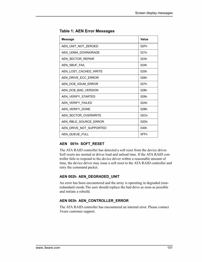
Screen display messages
AEN 001h SOFT_RESETThe ATA RAID controller has detected a soft reset from the device driver. Soft resets are normal at driver load and unload time. If the ATA RAID con-troller fails to respond to the device driver within a reasonable amount of time, the device driver may issue a soft reset to the ATA RAID controller and retry the command packet.
AEN 002h AEN_DEGRADED_UNITAn error has been encountered and the array is operating in degraded (non-redundant) mode.The user should replace the bad drive as soon as possible and initiate a rebuild.
AEN 003h AEN_CONTROLLER_ERRORThe ATA RAID controller has encountered an internal error. Please contact 3ware customer support.
AEN_UNIT_NOT_ZEROED 02Fh
AEN_UDMA_DOWNGRADE 021h
AEN_SECTOR_REPAIR 023h
AEN_SBUF_FAIL 024h
AEN_LOST_CACHED_WRITE 025h
AEN_DRIVE_ECC_ERROR 026h
AEN_DCB_XSUM_ERROR 027h
AEN_DCB_BAD_VERSION 028h
AEN_VERIFY_STARTED 029h
AEN_VERIFY_FAILED 02Ah
AEN_VERIFY_DONE 02Bh
AEN_SECTOR_OVERWRITE 02Ch
AEN_RBLD_SOURCE_ERROR 02Dh
AEN_DRIVE_NOT_SUPPORTED 030h
AEN_QUEUE_FULL 0FFh
Table 1: AEN Error Messages
Message Value
www.3ware.com 101

Troubleshooting: Problems and Solutions
AEN 004h AEN_REBUILD_FAIL
The ATA RAID controller was unable to complete a rebuild operation. This error can be caused by drive errors on either the source or the des-tination of the rebuild. However, due to ATA drives ability to reallocate sectors on write errors, the rebuild failure is most likely caused by the source drive of the rebuild detecting some sort of read error. The default operation of the ATA RAID controller is to abort a rebuild if an error is encountered. If it is desired to continue on error, the Ignore errors on rebuild radio button can be checked prior to initiating a rebuild.
AEN 005h AEN_REBUILD_DONEThe ATA RAID controller has successfully completed a rebuild. The comple-tion of the rebuild changes the state of the array from rebuilding to OK. The data is now redundant.
AEN 006h AEN_INCOMP_UNITAt power on initialization time, the ATA RAID controller performs a “roll-call” of all drives attached to the card. After detection of the drives, the ATA RAID controller then uses an internal algorithm to logically connect drives that belong to the same array. If after rollcall a member of an array is not found, the INCOMPLETE UNIT AEN is sent. Examples of incomplete units are as follows:
■ 4 drive RAID 5 with 1 drive missing.
■ 2 drive RAID 1 with 1 drive missing.
Replacing the missing or dead drive and initiating a rebuild will change the state of the array from an incomplete unit to OK.
AEN 007h AEN_INIT_DONEThe ATA RAID controller has completed the initialization sequence and per-forms the initialization step at array creation time of RAID levels 1, 10 and 5. For RAID 5, the data on the array is read and the resultant parity is written to the parity area on the array. For RAID 1 and 10, one half of the mirror is cop-ied to the other half (mirrors are synchronized).
AEN 008h AEN_UNCLEAN_SHUTDOWNThe ATA RAID controller has the ability to detect if the system has been shut-down via the standard shutdown mechanism of the operating system (clean shutdown). If the system loses power or is reset without going through the normal shutdown procedure, it is possible that the data on a redundant array may be out of synchronization. The unclean shutdown detection will detect
102 3ware Escalade ATA RAID Controller User Guide

Screen display messages
this case and force the array to enter the rebuilding state. This has the effect of synchronizing the array back to a fully redundant state.
To prevent unclean shutdowns, the user should always go through the normal shutdown procedure for the operating system in use and use an uninterruptible power supply (UPS) to prevent unclean shutdowns due to sudden power loss.
AEN 009h AEN_APORT_TIMEOUTThe ATA RAID controller has a sophisticated recovery mechanism to handle various types of failures of a disk drive. One such possible failure of a disk drive is a failure of a command that is pending from the ATA RAID controller to complete within a reasonable amount of time. If the ATA RAID controller detects this condition, it notifies the user, prior to entering the recovery phase, by displaying this AEN.
Possible causes of APORT time-outs include a bad or intermittent disk drive, power cable or ATA interface cable.
AEN 00Ah AEN_DRIVE_ERRORAs part of the recovery mechanism of the ATA RAID controller, various drive failures can be detected and if possible corrected. One such drive failure is when the drive indicates back to the ATA RAID controller that it was unable to complete a command. If the drive returns an error to the ATA RAID con-troller, the user is notified by this AEN.
AEN 00Bh AEN_REBUILD_STARTEDThe ATA RAID controller notifies the user whenever it starts a rebuild. The rebuild start may be user initiated (by selecting the rebuild button in the 3DM Disk Management Utility) or it may be auto initiated by a hot spare failover. In either case, the user is notified of the event by this AEN.
AEN 00Ch AEN_INIT_STARTEDThe ATA RAID controller notifies the user by this AEN whenever it starts an Initialization. Initialization occurs at array creation time.
AEN 00Fh AEN_SMART_FAILThe ATA RAID controller supports S.M.A.R.T. Monitoring. whereby the individual drives automatically monitor certain parametric information such as error rates and retry counts. By monitoring this data, SMART may be able to predict a drive failure before it happens, allowing a user to schedule service of the array before it becomes degraded. The SMART status of each drive attached to the ATA RAID controller is monitored daily. If a failure of any drive is determined to be likely, the user is notified by this AEN.
www.3ware.com 103

Troubleshooting: Problems and Solutions
AEN 02Eh AEN_REPLACE_DRIVE_TOO_SMALLThe ATA RAID controller notifies the user by this AEN when the replacement drive capacity is smaller than required. The replacement drive must be equal to or greater capacity than the drive it's replacing. For more information refer to the Hint on page 32.
AEN 02Fh AEN_UNIT_NOT_ZEROEDThe ATA RAID controller notifies the user by this AEN when verification fails because the array has not been initialized. This is normal for the first ver-ification that occurs on a RAID 1 or RAID 10 array.
AEN 021h AEN_UDMA_DOWNGRADEThe ATA RAID controller communicates to the ATA disk drives through the Ultra DMA (UDMA) protocol. This protocol ensures data integrity across the ATA cable by appending a Cyclical Redundancy Check (CRC) for all ATA data that is transferred. If the data becomes corrupted between the drive and the ATA RAID controller (e.g., an intermittent cable connection) the ATA RAID controller detects this as a UDMA CRC or cable error. The ATA RAID controller then retries the failed command three times at the current UDMA transfer rate. If the error persists, it lowers the UDMA transfer rate (e.g., from UDMA 100 to UDMA 66) and retries another three times. This AEN is sent to the user when the ATA RAID controller lowers the UDMA transfer rate.
Possible causes of UDMA CRC errors are intermittent or bad ATA interface cables or cable routing problems through electrically noisy environments (e.g., cables are too close to the power supply).
AEN 023h AEN_SECTOR_REPAIRThe ATA RAID controller supports a feature called dynamic sector repair to allow the unit to recover from certain drive errors that would normally result in a degraded array situation. For redundant arrays such as RAID 1, 10 and 5, the ATA RAID controller essentially has two copies of the users data avail-able. If a read command to a sector on a disk drive results in an error, it reverts to the redundant copy in order to satisfy the host’s request. At this point, the ATA RAID controller has a good copy of the requested data in its cache mem-ory. It will then use this data to force the failing drive to reallocate the bad sec-tor, which essentially repairs the sector. When a sector repair occurs, the user is notified by this AEN.
The fact that a sector repair AEN has been sent to the user is an indication of the presence of grown defects on a particular drive. While typical modern disk drives are designed to allow several hundred grown defects, special attention should be paid to any drive in an array that begins to indicate sector repair messages. This may be an indication of a drive that is beginning to fail. The user may wish to replace the drive, especially if the number of sector repair errors exceeds 3 per month.
104 3ware Escalade ATA RAID Controller User Guide

Screen display messages
AEN 024h AEN_SBUF_FAILThe ATA RAID controller, as part of its data integrity features, performs diag-nostics on its internal RAM devices. Once a day, a non-destructive test is per-formed on the cache memory. Failure of the test indicates a failure of a hardware component on the ATA RAID controller. This AEN is sent to notify the user of the problem.
AEN 025h AEN_LOST_CACHED_WRITETo improve performance, this ATA RAID controller features caching layer firmware. For write commands this means that it acknowledges it has com-pleted a write operation before the data is committed to disk. If the ATA RAID controller can not commit the data to the media after it has acknowl-edged to the host, this AEN is posted to the user.
Typically, the LOST CACHED WRITE notification would be an indication of a catastrophic failure of the drives in the array, such as loss of power to multi-ple drives in an array.
AEN 026h AEN_DRIVE_ECC_ERRORThis AEN may be sent when a drive returns the ECC error response to a ATA RAID controller command. The AEN may or may not be associated with a host command. Internal operations such as Background Media Scan post this AEN whenever drive ECC errors are detected.
Drive ECC errors are an indication of a problem with grown defects on a par-ticular drive. For redundant arrays, this typically means that dynamic sector repair would be invoked (see AEN 023h). For non-redundant arrays (JBOD, RAID 0 and degraded arrays), drive ECC errors result in the ATA RAID con-troller returning failed status to the associated host command.
AEN 027h AEN_DCB_XSUM_ERRORThe ATA RAID controller stores certain configuration parameters on a reserved area of each disk drive called the Drive Configuration Block (DCB). As part of power-on initialization, the ATA RAID controller performs a checksum of the DCB area to ensure consistency. If an error occurs, please contact 3ware technical support. The drive’s DCB has been corrupted.
AEN 028h AEN_DCB_BAD_VERSIONDuring the evolution of the Escalade product line, the format of the DCB has been changed to accommodate new features. The DCB format expected by the ATA RAID controller and the DCB that is written on the drive must be compatible. If an array that was created on a very old Escalade product is con-nected to a newer Escalade ATA RAID controller, this AEN is posted and the ATA RAID controller rejects the drive. Please contact 3ware technical support if this event occurs.
www.3ware.com 105

Troubleshooting: Problems and Solutions
AEN 029h AEN_VERIFY_STARTEDThe ATA RAID controller allows the user to verify data integrity on an array.The verification functions for different RAID levels are as follows:
■ JBOD. Verify = Media Scan
■ RAID 0. Verify = Media Scan
■ RAID 1. Verify = Compare of Mirror Sides
■ RAID 10. Verify = Compare of Mirror Sides
■ RAID 5. Verify = Parity Data = User Data
When the verification starts, this AEN is posted to the user.
AEN 02Ah AEN_VERIFY_FAILEDThis AEN indicates that the data integrity verification function (see AEN 029h) has terminated with an error. For each RAID level being verified, this may mean:
■ JBOD. A single drive returned an error, possibly because of a media defect.
■ RAID 0. A single drive returned an error, possibly because of a media defect.
■ RAID 1. One side of the mirror does not equal the other side.
■ RAID 10. One side of the mirror does not equal the other side.
■ RAID 5. The parity data does not equal the user data.
For JBOD and RAID 0, the most likely cause of the error is a grown defect in the drive. For out-of-synchronization mirrors, the error could be caused by improper shutdown of the array. This possibility applies to RAID 1, 10 and 5. A rebuild will re-synchronize the array.
AEN 02Bh AEN_VERIFY_DONEThis AEN indicates the data integrity verification function (see AEN 029h) was completed successfully. No errors were encountered.
AEN 02Ch AEN_SECTOR_OVERWRITEIf a read error is encountered during a rebuild and the user chooses to ignore the error, the sector in error is reallocated. The user is notified of the event by this AEN.
106 3ware Escalade ATA RAID Controller User Guide

Screen display messages
AEN 02Dh AEN_RBLD_SOURCE_ERRORIf an error is encountered during a rebuild operation, this AEN is generated if the error was on a source drive of the rebuild. Knowing if the error occurred on the source or the destination of the rebuild is useful for troubleshooting.
AEN 030h AEN_DRIVE_NOT_SUPPORTEDEscalade 8000 series Serial ATA Controller only support UltraUDMA-100/133 drives. This AEN indicates that an unsupported drive was detected during rollcall or a hot add. This AEN also could indicate that the Serial to Parallel converter was jumpered in the wrong place. The converter must be correctly jumpered to correspond to UDMA 100 or 133 drives.
AEN 0FFh AEN_QUEUE_FULLThis is an internal error. Please contact 3ware technical support.
www.3ware.com 107

Troubleshooting: Problems and Solutions
108 3ware Escalade ATA RAID Controller User Guide

www.3ware.com 109
Appendix A. Compliance and Conformity Statements
Federal Communications Commission Radio Frequency Interference Statement
This equipment has been tested and found to comply with the limits for a Class B digital device, pursuant to Part 15 of the FCC Rules. These limits are designed to provide reasonable protection against harmful interference in a residential installation. This equipment generates, uses and can radiate radio frequency energy and, if not installed and used in accordance with the instruc-tions, may cause harmful interference to radio communications. However, there is no guarantee that interference will not occur in a particular installa-tion. If this equipment does cause harmful interference to radio or television reception, which can be determined by turning the equipment off and on, the user is encouraged to try to correct the interference by one or more of the fol-lowing measures:
■ Reorient or relocate the receiving antenna.
■ Increase the separation between the equipment and receiver.
■ Connect the equipment into an outlet on a circuit different from that to which the receiver is connected.
■ Consult the dealer or an experienced radio/TV technician for help.
To maintain compliance with FCC radio frequency emission limits, use shielded cables and connectors between all parts of the computer system.

Appendix A. Compliance and Conformity Statements
110 3ware Escalade ATA RAID Controller User Guide
Microsoft Windows Hardware Quality Lab (WHQL)
3ware, Inc. is committed to Microsoft Windows Hardware Quality Labs (WHQL) certification for all its products. However, a product’s software driv-ers are typically submitted for certification at nearly the same time as their release to market. Since the certification process may lag behind the release of the drivers, please refer to our WEB site at www.3ware.com for current certi-fication information.
European Community Conformity State-ment
The StorSwitch Controller Card Model StorSwitch 4D is in conformity with the following Common Technical Regulations and/or normative documents:EN 55022 Limits and methods of measurements of radio interference characteris-
tics of information technology equipmentEN 61000-4-2 Electromagnetic compatibility (EMC) Part 4: Testing and measure-
ment techniques Section 2: Electrostatic discharge immunity testEN 61000-4-3 Electromagnetic compatibility (EMC) Part 4: Testing and measure-
ment techniques Section 3: Radiated, Radio-Frequency, Electromag-netic Field Immunity Test
EN 61000-4-4 Electromagnetic compatibility (EMC) Part 4: Testing and measure-ment techniques Section 4: Electrical fast transient/burst immunity test
EN 60950 Safety of information technology equipment, including electrical busi-ness equipment following the provisions of the Electromagnetic Com-patibility Directive 89/23/EEC Low Voltage Directive
.

Limited Warranty
www.3ware.com 111
Appendix B. Warranty, Technical Support and Service
Limited Warranty3-Year Hardware Warranty: 3WARE, INC. warrants this product against defects in material and workmanship for a period of thirty-six (36) months from the date of original purchase. 3ware, at no charge and at its option, will repair or replace any part of this product which proves defective by reason of improper workmanship or materials. Repair parts or replacement products will be provided by 3ware on an exchange basis and will be either new or refurbished to be functionally equivalent to new. Products or parts replaced under this provision shall become the property of 3ware.Software Warranty: 3WARE, INC. will replace a defective media purchased with this product for a period of up to 30 days from the date of purchase. For detailed terms and conditions, please see the Limited Hardware Warranty and Software License Agreement at our website:http://www.3ware.com/support/rma_form.asp3ware warranty service is provided by returning the defective product to 3ware.
ExclusionsThis warranty does not cover any damage to this product which results from accident, abuse, misuse, natural or personal disaster, or any unauthorized dis-assembly, repair or modification. 3ware shall not be liable for any incidental or consequential damages, including but not limited to loss of profits, other loss, damage or expense directly or indirectly arising from the customer's mis-use of or inability to use the product, either separately or in combination with other equipment, regardless of whether 3ware has been advised of the possi-bility of such damages. 3ware is not liable for and does not cover under war-ranty, any costs associated with servicing and/or the installation of 3ware products. This warranty sets for the entire liability and obligations of 3ware with respect to breach of warranty and the warranties set forth or limited herein are the sole warranties and are in lieu of all other warranties, expressed or implied, including warranties or fitness for particular purpose and mer-chantability.
Appendix B. Warranty, Technical Support and Service
112 3ware Escalade ATA RAID Controller User Guide
State Law ProvisionsThis warranty gives you specific legal rights and you may have other rights which vary from state to state. Some states do not allow the exclusion of inci-dental or consequential damages or allow limitation of implied warranties or their duration, so that the above exclusions or limitations may not apply.
Obtaining Warranty ProtectionTo obtain warranty service during the warranty period call 3ware toll free at (800)-945-7273 or (408) 523-1145 (direct) as soon as you have identified a problem with your Escalade ATA RAID Controller unit. You will be issued a return material authorization (RMA) number. 3ware will send a replacement within two business days after receipt of the defective unit.
Advanced replacement is available with a credit card number with authoriza-tion in the amount equaling the then current list price of the Escalade ATA RAID Controller, including shipping costs. As soon as practicable thereafter, 3ware will ship the advanced replacement to you at the address of your choos-ing. Upon receipt of the advanced replacement, we ask that you immediately ship the defective Escalade ATA RAID Controller to 3ware at 455 West Maude Avenue, Sunnyvale, CA 94085. If 3ware receives the defective Escalade ATA RAID Controller from you within thirty (30) days of the date of shipment of the advanced replacement, 3ware will destroy your credit card authorization and you will not be charged for the advanced replacement.
Please use the original packing material contents of the box when exchanging or returning a product.
3ware Technical Support and ServicesProduct information, Frequently Asked Questions, software upgrades, driver files and other support are available through the 3ware World Wide Web site at http://www.3ware.com. 3ware’s software library is accessible at:http://www.3ware.com/support/download.asp
Web-based software downloads feature upgrading multiple switches simulta-neously.
For specific answers to questions or to give feedback about the product, visit our Web site at http://www.3ware.com/support and use our convenient e-mail form. 3ware also offers toll-free (800) 945-7273 and (408) 523-1145 direct phone support during normal business hours.

Sales and ordering information
www.3ware.com 113
Sales and ordering informationFor sales information, send an electronic mail message to [email protected].
Feedback on this manualYour feedback is welcome. If anything in the guide seems unclear please let us know by sending e-mail to [email protected].

Appendix B. Warranty, Technical Support and Service
114 3ware Escalade ATA RAID Controller User Guide

www.3ware.com 115
Numerics3DM 79
installing for Windows 80starting 83uninstalling 83
3DM Disk Management Utility 793DM password 893DM, installing for Linux
3DM for Linux 81
AAccelerated Graphics Port (AGP) 19, 22, 25array
creating 12, 15, 31deleting 36maintaining 37modifying 36verifying 37
Array Configuration Utility 27Array status, checking 84ATA cables 98ATA/100 19, 20ATA/133 19, 20ATA/33 23ATA/66 23auto initialize on power failure 43Auto rebuild of a redundant array 93auto rebuild of mirrored or RAID 5 array 43Available Drives, listed in BIOS 30
BBackground Media Scan 12Background Task Rate 91backplane, using with multi-lane connectors 24BIOS 11, 29, 97BIOS tool 28
Ccancelling rebuild 43changing existing configuration 36CLI (Command Line Interface) 27
compiling the driver for FreeBSD 77Compliance and Conformity 109
Ddefective drive, replacing with spare 28Deleting a disk array 36deleting a disk array 36Determining your configuration 29disk array
deleting 36maintaining 37modifying 36verifying 37
Disk Array Configuration Utility 98Disk Arrays, listed in BIOS 30Disk Druid partitioning utility 98Download Error Log 87drive
adding a new one to a controller 46Drive Configuration Block (DCB) 105drive status connector 18, 21Drive types 4drivers
installing under Linux 63installing under Windows 49updating under Windows 52upgrading 54
Dynamic Sector Repair 13, 104
EEscalade 7European Community Conformity 110Extended Error Log 87
FFCC 109Force Continue on Rebuild 93FreeBSD Installation 73
HHardware Installation 17hot spare 27, 36
Index

Index
116 3ware Escalade ATA RAID Controller User Guide
designating 28designating in 3DM 28
hot spare, specifying 93Hot swap 12hot swap 27
Iinitialization
RAID 1 or 10 35RAID 5 35
initialize (auto) 43installation
under Linux 61under Windows 45
installing3DM for Windows 80parallel ATA RAID controller 18serial ATA RAID controller 21serial ATA RAID controller with multi-lane
internal connectors 24installing controller
on FreeBSD that boots from a different device 75
when Windows boots from different device 49while installing FreeBSD 74while installing Red Hat Linux 62while installing SuSE Linux 68while installing Windows 47
LLED drive status connector 18, 21Linux 15Linux, installation 61
Mmaintaining a disk array 37mirrored array
rebuilding 38modifying disk array 36motherboard boot sequence 26multi-lane internal connectors 24
OOperating systems 15
PPassword 89, 91password for 3DM 89PCI slot 19, 22, 25Personal safety 4
power failure causes auto initialize 43
RR5 Fusion 11RAID 8, 33RAID 0 8, 33RAID 1 8, 9, 33, 34, 38RAID 1 or 10 initialization 35RAID 10 8, 9, 34RAID 5 8, 10, 34, 40RAID 5 initialization 35RAID array initialization 48, 63rebuild
cancelling 43Rebuild Array 42rebuild process 93rebuilding
mirrored disk array 38Rebuilding a mirrored array with no hot spare 40Rebuilding a mirrored disk array 40Rebuilding RAID 5 40Rebuilding with Hot Spare 40rebuilding with hot spare 43Red Hat Linux installation 62Remote Access 91removing an existing Escalade controller 17
SSerial ATA 8serial ATA RAID controller with multi-lane
internal connectors 24SMART 11, 87, 103Staggered Spin Up 12status connector for drive (LED) 18, 21stripe size, selecting 34System requirements 4
TTechnical Support 111Tools required 4Troubleshooting 97TwinStor 11
UUltra DMA protocol 104uninstalling 3DM 83upgrading the 3ware driver 54

www.3ware.com 117
Vverify array 37
WWarranty 111WHQL 110Windows Installation 45Windows XP, Windows 2000, Windows Server
2003 15write cache properties, selecting 34
YYaST2 68

Index
118 3ware Escalade ATA RAID Controller User Guide