esi communications servers programming manual · esi communications servers programming manual...
TRANSCRIPT

ESI Communications Servers ESI-1000 • ESI-600 • ESI-200 • ESI-100
Programming Manual
0450-1050 Rev. B
Copyright © 2007 ESI (Estech Systems, Inc.). IVX is a registered trademark of Estech Systems, Inc. Ethernet is a registered trademark of Xerox Corporation. Motorola and ColdFire are registered trademarks of Motorola, Inc. Rayovac is a registered trademark of Rayovac Corporation. Act! is a registered trademark of Symantec Corporation. Goldmine is a trademark of Goldmine Software Corporation. Microsoft, Windows, NT and Outlook are registered trademarks of Microsoft Corporation. Panasonic and DBS are registered trademarks of Matsushita Electric Corporation of America. Novell and Netware are registered trademarks of Novell, Inc. Smart Jack is a trademark of Westell Technologies, Inc. Information contained herein is subject to change without notice. Certain features described herein may not be available at initial release. ESI products are protected by various U.S. Patents, granted and pending. ESI is an ISO 9001:2000-certified company. Visit ESI on the Web at www.esicomservers.com.

Contents
General description ..............................................................A.1 Flexible numbering................................................................. A.3
System capacities .................................................................B.1
Remote maintenance with ESI System Programmer ...C.1
System programming: An introduction...........................D.1
Function 1: System parameters.........................................E.1 Function 11: Initialize ............................................................. E.1 Functions 12 and 13: Installer and Administrator passwords..... E.1 Function 14: System clock ..................................................... E.1 Function 15: System timing parameters................................. E.3 Function 16: System feature parameters ............................... E.4 Function 17: System speed-dial........................................... E.11 Function 18: Maintenance/SMDR serial port........................ E.12
Function 2: CO lines .............................................................F.1 Function 21: CO line programming .........................................F.1 Function 22: Translation table programming.........................F.15 Function 23: CO line parameters ..........................................F.23 Function 24: Caller ID ...........................................................F.25
Function 3: Extension programming............................... G.1 Function 30: Station move .....................................................G.1 Function 31: Extension definition and routing.........................G.2 Function 32: Extension feature authorization .......................G.15 Function 33: Department programming................................G.18 Function 34: Flexible number assignment............................G.25 Function 35: Extension button mapping ...............................G.26 Function 37: RFID programming..........................................G.30
Function 4: Auto attendant programming.......................H.1 Function 41: Auto attendant branch programming .................H.1 Function 42: Announce extension number.............................H.6 Function 43: Automatic day/night mode table.........................H.7
Function 5: Voice mail programming ................................ I.1 Function 51: Maximum message/recording length .................. I.1 Function 52: Message purge control ....................................... I.1 Function 53: Guest/info mailboxes .......................................... I.2 Function 54: Group mailboxes and the broadcast mailbox ...... I.3 Function 55: Message notification ........................................... I.3 Function 56: Cascade notification mailboxes........................... I.5 Function 57: Q & A mailboxes ................................................. I.6 Function 58: Message move and delete.................................. I.6
Function 6: Recording..........................................................J.1 Function 61: Re-record system and branch prompts .............. J.1 Function 62: Record directory names..................................... J.2 Function 63: Message-on-hold (MOH) programming.............. J.3
Function 7: Reports.............................................................. K.1 Report printing........................................................................K.1 Reporting functions ................................................................K.1
Feature description: SMDR .................................................L.1 Tabular SMDR format ............................................................ L.1 CSV SMDR format................................................................. L.2 Reporting conventions and rules ............................................ L.3 SMDR format when using account codes............................... L.4
Function 8: IP PBX programming.....................................M.1 Function 81: Display licenses ................................................ M.1 Function 82: Local IP PBX programming............................... M.2 Function 83: Esi-Link programming....................................... M.8
Index
Important: For information concerning the hardware installation for an ESI Communications Server (the ESI-1000,
ESI-600, ESI-200, or ESI-100), see the ESI Communications Servers Hardware Installation Manual (ESI document #0450-1049).

ESI Communications Servers Programming Manual General description
A.1
General description
ESI Communications Servers — the ESI-1000, ESI-600, ESI-200, and ESI-100 — are versatile, scalable telecommunications systems for sophisticated enterprise applications. Each represents the latest generation of ESI’s advanced telecommunications systems, and provides much more than standard phone service. Standard
features include voice mail, automated attendant, automated call distribution (ACD), external paging interface, and extensive call coverage features (such as off-premises “reach-me”). Optional features include computer/telephony integration and advanced voice over IP (VoIP) communications, allowing your customers to transition smoothly from traditional circuit-switched telephony to cost-efficient IP network-based telephony.
You or an Administrator can program the system locally or remotely, through either a phone or ESI’s Windows®-
based ESI System Programmer application. Each application runs on a Windows®-compatible computer which is
connected to the system locally via serial port, remotely via the system’s built-in modem, or over Ethernet® via
the system’s built-in Network Services Processor (NSP).
Notes: Throughout this document, except where noted, we refer to each ESI port card by its functional descriptor (usually a number), WITHOUT any “E2” or “CS” modifiers. An “E2” card and a “CS” card with the same functional descriptor — e.g., an E2-684 and a CS-684 — are functionally identical. The difference is
that the ESI-100 accepts only “E2” port cards, while other ESI Communications Servers accepts both “E2” and “CS” port cards.
1
Except where noted, the remainder of this “General description” chapter describes only features, rather than
any system capacities. For system-specific capacity specifications — e.g., CO lines, ports, message storage, etc. — see “System capacities” (page B.1).
Telephone system features
• Impressive expansion capability — Each system accepts one or more Expansion Cabinets to maximize its potential call-handling.
• T1 and PRI support — Can connect to higher-bandwidth lines, which more and more offices use.
• ESI Feature Phones — Compact and stylish, yet rugged, each ESI Feature Phone includes a high-quality speakerphone, large and informative multi-functional display and a specially designed key layout with several dedicated keys to minimize or eliminate the need to memorize codes. ESI’s 48-Key Feature Phone comes in a variety of formats: digital, digital with TAPI, and IP. Each 48-Key Feature Phone model includes an integrated headset jack. Also available: 24-Key Feature Phone, 12-Key Feature Phone, and Cordless Handsets.
2
Note: The 12-Key Feature Phone has the same stylish, rugged ESI Feature Phone design and offers the most basic phone functions. It is intended for use in areas such as lobbies, cashier stations, warehouses and
employee lunchrooms, where only minimal phone system features are needed.
• Extensive help — ESI’s Verbal User Guide™ uses spoken and displayed help prompts to help everyone from the Installer through the Administrator down to the least experienced end user. Easily accessible with one press of either the HELP key on the 48-Key Feature Phone or the PROG/HELP combo key on the 24-Key Feature Phone. One can also visit www.esiusers.com for comprehensive help.
• Enhanced Caller ID — Allows one-touch automatic message return.3 An ESI Communications Server
passes Caller ID data to both digital and analog ports.
• Live call recording — Can record any conversation or personal memo, with moving or copying of any recording to another user’s voice mailbox (see “Voice mail features,” below).
• Call waiting — Includes helpful display, showing both calls’ Caller ID information, and easy one-key toggling between calls.
• Conference calling — Includes up to 64 dynamic conference ports; a single conference may contain up to 16 members.
4 Conference bridges are dynamic, so possible conference sizes include: 21 three-member; 16
four-member; 10 six-party; and various combinations in-between. Analog phones on the system also may originate conferences.
1 In the ESI-1000, ESI-600, and ESI-200, use of an “E2” port card also requires a “Hot Swap” Port Card Adapter (ESI part #5000-0385).
2 See also the ESI Communications Servers Hardware Installation Manual (ESI document #0450-1049).
3 This and all other references to Caller ID service within this manual assume the end-user organization subscribes to Caller ID service from its
telephone service provider. 4 See “System capacities” (page B.1).
ESI Communications Servers Programming Manual General description
A.2
• Esi-Dex™ speed-dialing — Calls any number using four separate lists (personal, station, system and — when Esi-Link is in use — location); uses Caller ID information or direct keypad entries.
• Dedicated overhead paging interface — Allows for external paging through overhead speakers or multi-zone paging units (amplification required) and separate, vendor-supplied zone page adapters.
• Intelligent Call Forwarding™ — Lets users of compatible PRI-equipped ESI systems view the original Caller ID data of a call forwarded to an off-premises phone.
• 911 alert — Provides immediate line access if any station1 dials 9 1 1 to report an emergency; sends a
message via the serial port indicating the start date, time, station number and end-time of the 911; also sounds an audible warning at the operator station and displays, for example:
911 CALL FROM X102 JOHN JAMES
Important: Remember to advise your customers not to make 911 calls using a remote IP phone.2 Because such a
phone isn't connected directly to the local telephone network, it’s necessary instead to use a regular phone connected locally, not the remote IP phone, to make 911 or other emergency calls. (For more information, see the documentation included with the remote IP phone.)
• Shared-office tenanting — Tenant service allows multiple business entities to share a telephone system while maintaining separation of various facilities and features. For more details, see “Shared-office tenanting,” page A.3.
• Support for these options:
– Esi-Link — Allows a multi-site enterprise to network any combination of dozens of compatible ESI phone
systems across an IP-based network. For details, see the Esi-Link Product Overview (ESI document # 0450-0214).
– VIP™
— Provides a value-added interface to an ESI Communications Server. Delivers call control and
unified messaging to Microsoft® Outlook
® 2000/2002/2003/2007. For details, see the VIP Product
Overview (ESI document # 0450-0608) and VIP ACD Product Overview (ESI document # 0450-0988).
– ESI Presence Management — Provides integrated building entry control, access control, status
indication, personal call routing, and (optionally) time and attendance management. For details, see the ESI Presence Management Product Overview (ESI document # 0450-0794).
Voice mail features
• Built-in voice mail ports — These are in addition to the call-processing ports; thus, you may build the system to its maximum for call-handling without having to balance voice mail needs versus call-handling needs. For specific voice storage capacities on a system-by-system basis, see “System capacities” (page B.1).
• Highest-grade voice quality (64-kilobit/second sampling) for voice mail and other storage of voice messages.
• Message-on-hold (MOH) recordings — Among these are three prerecorded tracks; also supports live entry. With tenant service enabled (see “Tenant service features,” page A.3), each tenant has its own MOH source.
• Off-premises message delivery — Automatically delivers voice messages to designated phone number, such as a cell phone, when one is out of the office.
• Urgent messages — Can deliver higher-priority messages first.
• Several different mailbox types, including group, broadcast, informational, cascade notification and Q & A.
• Message Recycle Bin (undelete) — Remembers, and can restore, each mailbox’s 10 most recently deleted messages.
• Quick Groups™
— Makes it easy to leave voice mail messages for several users.
• Quick Move™
— Records a conversation into another user’s mailbox.
• Virtual Mailbox Key™
allows easy monitoring of a second mailbox.
1 An ESI Remote IP Cordless Handset sends 911 calls via the local analog CO line attached to the Cordless Handset’s base station. The 911 alert
information isn’t available at the operator station or via serial port. 2 A remotely installed IP Feature Phone II, a Remote IP Cordless Handset, or a remote installation of VIP Softphone.

ESI Communications Servers Programming Manual General description
A.3
Auto attendant features
• Six levels, 100 branches — Allow you and your customer to set up a more caller-friendly answering environment, including a company directory.
• Virtually unlimited call routing — Includes off-premises transfer, pager notification, more.
ACD features
• Routes calls within designated departments for quickest possible call answering.
• Uses three-line Digital Feature Phone display to provide up-to-the-second information on queues, wait times, delay announcement, priority queueing, and overflow routing.
• Optional VIP ACD Supervisor and VIP ACD Agent enhance ACD usage; VIP ACD Supervisor offers highly useful reports and also gives ability to customize reports.
1
Shared-office tenanting
• Can be configured to support up to eight tenants.2
• CO lines — CO line groups and corresponding access codes can be used to separate each tenant’s CO lines if required. “Pooled” or shared lines can be assigned to a line group to which all stations are allowed access. CO lines are assigned to tenants for the purpose of following each tenant’s day/night mode.
• Stations and departments — Each station and department can be assigned to one tenant.
• Automatic day/night mode — If this is enabled, each tenant will follow day/night mode changes assigned in its unique table.
• Day/night key — A day/night key may be assigned to select day or night mode manually for each tenant.
• Auto attendant day/night greeting — Each tenant may use a dedicated day/night branch ID3 to route to a
destination. Day/night routing will be controlled either automatically by each individual tenant’s day/night tables or manually by use of a day/night key for each tenant.
• Message-on-hold (MOH) — Each tenant will have a unique customer-recorded MOH source.
• Central answering — Central answering makes it possible for one extension (or department) to answer incoming calls to different tenants.
• Operator (dial-“0”) routing — Unique operator call routing may be assigned to each tenant.
Flexible numbering
Flexible numbering provides the means to assign extension, voice mailbox, and department numbers based on specific customer requirements. ESI’s flexible numbering is separated into three parts:
1. Selection of a starting numbering plan template.
2. Reassignment of ranges of extensions and (if needed) guest mailboxes.
3. Reassignment of individual extensions and (if needed) guest mailboxes and department numbers.
Selectable numbering plans (Function 169)
The selectable numbering plan template is the basis for flexible numbering assignment. When a numbering template is selected, all extensions, mailboxes, departments, and other system features are automatically assigned with the numbering plan of that template. Choosing the template that is closest to the customer’s existing configuration greatly simplifies, or even eliminates the need for, number reassignment. (See “Selectable numbering plan,” page D.2.)
Note: Full system capacity can be achieved only through use of a four-digit selectable numbering plan (see
page D.2).
1 Report customization requires either Crystal Reports Standard Edition or Crystal Reports Professional Edition (not available from ESI).
2 See “System capacities” (page B.1).
3 See “Function 41: Auto attendant branch programming,” pp. H.1–H.6.

ESI Communications Servers Programming Manual General description
A.4
Range reassignment (Function 34 extended; ESI System Programmer only)
Included in ESI System Programmer, flexible number range assignment is used to change the numbers of
a block, or range, of extensions or guest mailboxes.1 Range reassignment can be used either at time of
installation or after the system is installed.
Number reassignment (Function 34)
Number reassignment lets you assign new, or reassign existing, individual extensions, departments, and guest mailbox numbers.
Station move (Function 30)
Station move is used by the Installer or System Administrator to move, or exchange, extension numbers and other station information between extensions of the same station type.
2 Programmable feature keys, personal
greetings, voice mail messages, and other system information are automatically and instantly exchanged between the two stations when this is done.
Esi-Link and flexible numbering: Limitations
The following table lists the Esi-Link compatibility of various ESI products with an ESI Communications Server using flexible numbering.
REMOTE site’s ESI system REMOTE site’s
system software version
LOCAL system’s
numbering plan template
Resulting Esi-Link
compatibility
ESI-1000, ESI-200, or ESI-100 [All] Any Complete
Feature Set II (16.1.0 or higher) Any Complete ESI-600
Feature Set I (15.2.x or lower) Any Limited
Any three-digit Limited 10.6.0 or higher
Any four-digit None
Dial plan template 100 Limited IVX X-Class
10.5.x or lower Any other dial plan None
Any three-digit Limited 2.5.2 or higher
Any four-digit None
Dial plan template 100 Limited IVX E-Class Generation II
2.5.1 or lower Any other dial plan None
In this chart, limited compatibility means that, when you use Function 34 (number reassignment), you must keep the extension and mailbox ranges within their original numbering plan template ranges.
Example: Let’s say your local system is an ESI-600 using numbering plan 100. If you swap extension 100 with
mailbox 300 — i.e., so that station 100 is now extension 300, and mailbox 300 is now mailbox 100 — an IVX X-Class system that dials station 300 over Esi-Link won’t be able to process the call correctly,
because that station is no longer within the numbering template. However, if you merely swap extensions 100 and 120 on that same ESI-600, an Esi-Linked IVX X-Class will be able to process a call to extension 120 (because the changed extension is still within the numbering template).
For proper operation, two or more Esi-Linked ESI Communications Servers of the same model should all be running the same system software version. However, an ESI system without flexible numbering-compatible system software will still be compatible with an ESI Communications Server with flexible numbering-compatible system software; yet, the ESI Communications Server with flexible numbering will remain subject to the same Function 34-related limitations described above.
1 Range assignment of department numbers and special-purpose mailboxes is not supported at initial release of this system software. However,
Function 34 can be used to reassign department numbers. 2 Such stations must be like types — e.g., Digital Feature Phone to Digital Feature Phone, IP Feature Phone to IP Feature Phone, or analog
extension to analog extension.

ESI Communications Servers Programming Manual System capacities
B.1
System capacities
Important: Each ESI Presence Management RFID Reader uses one digital station.
Stations and trunks
The specifications shown below reflect maximum capacities and configurations. Not all of the station and trunk maximums can be reached simultaneously.
Example: The ESI-100 can’t achieve 72 IP stations and 48 digital stations and 28 analog stations and 42 trunks and 24 Esi-Link stations at the same time, because the system’s four-port-card limit makes such a
configuration impossible. The maximum configuration for this system is 108 ports, which could be achieved by one DLC12 card (24 T1 trunks, 12 digital stations), two IVC 24Rs (48 IP stations), and one IVC EL24 (24 Esi-Link channels).
ESI-1000 ESI-600 ESI-200 ESI-100
Dialing plans (-digits) Four Three Four Three Four Three Four Three
Max. port cards 42 14 28 14 14 14 4 4
Max. port configuration1 1,128 276 624 276 300 276 108 108
– Max. stations 816 168 408 168 192 168 84 84
– Max. IP stations 816 168 408 168 192 168 72 72
– Max. digital stations 504 168 336 168 168 168 48 48
– Max. analog stations 384 56 188 56 56 56 28 28
Max. CO lines 240 84 168 84 84 84 42 42
Max. DLCs (T1/PRI) 10 3 6 3 3 3 1 1
Max. IVCs 34 7 17 7 8 7 3 3
Max. Esi-Link port cards (up to 24 Esi-Link channels
2 per card)
4 4 2 2 1 1 1 1
Dedicated ports ESI-1000 ESI-600 ESI-200 ESI-100
Dialing plans (-digits) Four Three Four Three Four Three Four Three
Voice mail/auto attendant ports3 128 128 32 32 16 or 24 16 or 24 8 8
Conference ports (max. of 16 members per conference)
64 64 64 64 24 24 16 16
NSP4 1 1 1 1 1 1 1 1
Overhead paging ports5 1 1 1 1 1 1 1 1
Serial/SMDR ports 1 1 1 1 1 1 1 1
Voice mail capacities ESI-1000 ESI-600 ESI-200 ESI-100
Dialing plans (-digits) Four Three Four Three Four Three Four Three
Voice mail storage (hours) 1,200 1,200 1,200 1,200 140 or 600 140 or 600 140 140
Broadcast mailbox (one to all extensions)
Yes Yes Yes Yes Yes Yes Yes Yes
Cascade notification mailboxes 40 10 20 10 10 10 10 10
Group mailboxes/max. members 64/200 32/200 32/64 32/64 16/48 16/48 16/32 16/32
Guest/info mailboxes 1,000 190 1,000 190 1,000 190 1,000 190
Maximum station mailboxes 816 168 408 168 192 168 84 84
Q & A mailboxes 20 10 20 10 10 10 10 10
1 Includes Esi-Link channels.
2 Esi-Link channels are allocated to “reserved” ports; i.e. Esi-Link channels do not reduce CO or station capacity.
3 On the ESI-200: 16 ports for 140-hr. model, 24 ports for 280-hr. and 600-hr. models.
4 Network Services Processor; see the ESI Communications Server Hardware Installation Manual (ESI # 0450-1049).
5 On the ESI-200: A non-IVC card must be installed in slot 1 or 2. On the ESI-100: An IVC can’t be installed in slot 1.

ESI Communications Servers Programming Manual System capacities
B.2
Departments ESI-1000 ESI-600 ESI-200 ESI-100
Dialing plans (-digits) Four Three Four Three Four Three Four Three
Max. departments 128 20 64 20 20 20 10 10
Department types: Ring-all, ACD, UCD, in-order, pick-up, attendant
Yes Yes Yes Yes Yes Yes Yes Yes
Max. members, non-ring-all depts. 64 64 64 64 48 48 32 32
Max members, ring-all depts. 48 48 48 48 48 48 32 32
Shared-office tenanting ESI-1000 ESI-600 ESI-200 ESI-100
Dialing plans (-digits) Four Three Four Three Four Three Four Three
Tenants 8 8 8 8 4 4 2 2
CO line groups ESI-1000 ESI-600 ESI-200 ESI-100
Dialing plans (-digits) Four Three Four Three Four Three Four Three
Line groups 9, 8, 71–76 Yes Yes Yes Yes Yes Yes Yes Yes
Max. members, CO ring assignment list
48 48 48 48 48 48 32 32
Translation tables ESI-1000 ESI-600 ESI-200 ESI-100
Dialing plans (-digits) Four Three Four Three Four Three Four Three
PRI pilot numbers 80 80 40 40 20 20 10 10
Max. DID entries 1,200 1,200 600 600 300 300 300 300
System speed-dial numbers ESI-1000 ESI-600 ESI-200 ESI-100
Dialing plans (-digits) Four Three Four Three Four Three Four Three
System speed-dial numbers 1,000 100 1,000 100 1,000 100 1,000 100
Maximum installations of VIP applications ESI-1000 ESI-600 ESI-200 ESI-100
Dialing plans (-digits) Four Three Four Three Four Three Four Three
Installations, VIP PC Attendant Console
16 16 8 8 4 4 2 2
Installations, VIP auto-recording
32 32 16 16 8 8 4 4
Installations, VIP ACD Supervisor
16 16 8 8 4 4 2 2
ESI Presence Management features ESI-1000 ESI-600 ESI-200 ESI-100
Dialing plans (-digits) Four Three Four Three Four Three Four Three
RFID Reader access door records
50,000 50,000 10,000 10,000 10,000 10,000 10,000 10,000
RFID Reader entries in Function 372
1
64 64 32 32 32 32 16 16
Max. RFID tags (“electronic keys”)
2,000 2,000 500 500 500 500 500 500
1 See the ESI Presence Management Installation Manual (ESI document #0450-0792).

ESI Communications Servers Programming Manual Remote maintenance with ESI System Programmer
C.1
Remote maintenance with ESI System Programmer
ESI System Programmer gives the Installer the capability to program all phone system features, including IP addresses for Remote Phones and Esi-Link. ESI System Programmer can be used from a PC or laptop connected directly to the system on-site; it can also connect to the system remotely via TCP/IP or dialup.
ESI System Programmer can be used remotely by the Installer to make adjustments to a site’s ESI Communications Server. This section will cover how to use ESI System Programmer in conjunction with the system’s Network Services Processor (NSP) for remote maintenance.
Required equipment and information:
• A programmed and connected NSP in the site’s ESI Communications Server. (The NSP itself is standard.)
• You will also need to know the site’s NSP IP address: _____________________.
• The PC or laptop must have an Ethernet interface and have a broadband connection to the LAN, WAN, or Internet (depending upon the type of remote connection involved).
• TCP/IP port number 59002 for the site’s router.
ESI System Programmer setup
1. Contact the site to port-forward TCP/IP port 59002 from the router to the NSP’s IP address. Verify that the port prefix of 59 hasn’t changed (if it changed to 56, for example, the port number would be 56002 rather
than 59002). If the customers are unaware how to port-forward, have them refer to the router’s User’s Guide.
Important: For an explanation of how the port forwarding works, see “Configuring the remote office NAT router” in the NSP/VIP Advanced Options Guide (ESI part #0450-0667).
2. After port forwarding is complete, install ESI System Programmer on your PC. ESI System Programmer
can be found on the software page of the Resellers’ Web site: www.esiresellers.com/software.
3. Follow directions in the ESI System Programmer User’s Guide (# 0450-1046) for setting up a site.
Connecting to the site
Important: ESI strongly recommends connecting to the ESI
Communications Server via the NSP, for a faster and more stable connection.
Once the site is created and the network settings are entered,
connect to the site using network communications:
1. Highlight the site and right-click. In the resulting drop-down menu, click Connect, then Network/NSP.
2. Once the dialog box shows you’re connected, click Close and then begin programming
Once you are connected to the site, you can program features as if you were actually there.

ESI Communications Servers Programming Manual System programming: An introduction
D.1
System programming: An introduction
You can program an ESI Communications Server either (a.) from a 24-Key or 48-Key Feature Phone1 in the
system or (b.) with the Windows®-based ESI System Programmer package. Both methods follow the same
programming steps. This manual focuses on programming from a Feature Phone; the respective documentation
for ESI System Programmer details the differences in programming from that environment.
Read the User’s Guide first. Programming features require a clear understanding of user interface and application.
Once you’ve accessed programming mode on a 24-Key or 48-Key Digital Feature Phone, the system will prompt for — and confirm — each keystroke action via voice commands and the display. You program both configuration data and recordings in the same manner.
Important: During programming, the 24-Key Feature Phone’s two-line display shares the same content as the top two
lines of the 48-Key Feature Phone’s three-line display. As a result, to save space, the sample displays shown herein will show only two lines.
If installing ESI Presence Management on this system, refer to the ESI Presence Management Installation
Manual (ESI # 0450-0792) for important information before you program the system.
Programming keys
During programming, the first line of the display will show the current item being programmed, and the second line will be the entry line. You can enter values as directed by the combination of the voice prompts and display. To enter multiple values, such as a list of extension numbers, separate each value by # (to exit the list, enter # #).
To... Press ... What this does
Enter # Confirms new or existing entry and advances to next
programming step.
Back up (i.e., reverse direction) Backs up to previous prompt without changing its value.
Delete HOLD Deletes data or recording.
Exit [Hang up] Exits programming mode and removes extension from DND.
Help HELP Provides more detailed instructions during programming.
(left-side scroll key) • During entry of a value, backs up.
• If a list is present (“>” is displayed), scrolls to left.
Select/scroll
(right-side scroll key)
• Selects from options presented.
• If a list is present (“>” is displayed), scrolls to right.
• Inserts a space during entry of a name.
Notes: Either < or > in the display indicates that additional choices or values are available by pressing a
corresponding scroll key ( or ).
Only one person at a time can be performing Installer or Administrator programming.
1 ESI doesn’t recommend programming the system using a 12-Key Feature Phone, and you cannot do so using an ESI Cordless Handset.

ESI Communications Servers Programming Manual System programming: An introduction
D.2
Entering alphanumeric characters
You enter names for extensions, departments, branch IDs, CO lines, guest mailboxes and DIDs by pressing the dial pad key that corresponds to the character to be entered. The key’s possible entries will change each time the key is pressed, and the display will show this. When the desired character appears on the display, press # to confirm; the cursor will move to the next character position. You may move the cursor left (to correct
an entry) by pressing the left scroll key ( ) or move right (to add a space) by pressing the right scroll key ( ).
Key Options Key Options
0 0, - (hyphen), _ (underline) 7 P, R, S, 7
1 Q, Z, 1, “_” (space) 8 T, U, V, 8
2 A, B, C, 2 9 W, X,Y, 9
3 D, E, F, 3 (left scroll key) Backs up and erases
4 G, H, I, 4 (right scroll key) Adds a space
5 J, K, L, 5 # [Enter]
6 M, N, O, 6 # # Ends the name
Example: To enter a B, press 2 twice (the possible options to scroll through are A, B, C and 2). When B is displayed,
press # to confirm; the cursor will move to the next character to be entered. To complete the name, press # #.
Note: On an incoming call, the name you assigned to the call’s CO line or DID — rather than the Caller ID data —
will appear until the call is answered.
Selectable numbering plan
The ESI Communications Server’s selectable numbering plan offers up to nine pre-configured ranges — three three-digit plans and six four-digit plans. When an extension range is selected, department numbers and guest mailbox numbers are also changed. However, regardless of which extension range is selected, feature key codes, and CO line group access numbers will stay the same. The dial plan range is selected through Installer programming Function 169 (see page E.10 for more information).
Notes: The ESI Presence Management RFID Reader1 uses one digital extension, regardless of dial plan.
The IP Feature Phone II, the IP Cordless Handset (Local or Remote), VIP Softphone, and a SIP phone each use one IP port, regardless of dial plan.
Important: Full capacity on the ESI-1000, ESI-600, or ESI-200 can be achieved only by using a four-digit plan.
(See “System capacities,” page B.1.)
1 For more information, see the ESI Presence Management Installation Manual (ESI # 0450-0792).

ESI Communications Servers Programming Manual System programming: An introduction
D.3
Three-digit numbering plan selections (all ESI Communications Servers)
Selection 100 (default) Selection 200 Selection 300
From To Used for From To Used for From To Used for
100 267 Extensions 200 367 Extensions 300 467 Extensions
280 299 Departments 380 399 Departments 470 489 Departments
300 489 Guest/info mboxes 100 199 Guest/info mboxes 100 289 Guest/info mboxes
400 489 Guest/info mboxes
Common to all three-digit numbering plan selections (all models)
From To Used for From To Used for
0 — Operator 700 709 Esi-Link1 locations
490 499 Q & A mailboxes 770 799 Esi-Link locations
500 — Broadcast mailbox 71 76 Esi-Link/CO line grps.
501 532 Group mboxes 8 — CO line grp.
533 542 Cascade notif. mboxes 9 — CO line grp./ARS
600 699 System speed-dial — Call pickup
# — Paging
Four-digit numbering plan selections (ESI-1000 only)
Selection 1000 Selection 2000 Selection 3000
From To Used for From To Used for From To Used for
1000 1815 Extensions 2000 2815 Extensions 3000 3815 Extensions
1872 1999 Departments 2872 2999 Departments 3872 3999 Departments
3000 3999 Guest/info mboxes 3000 3999 Guest/info mboxes 2000 2999 Guest/info mboxes
4000 — Broadcast mailbox 4000 — Broadcast mailbox 4000 — Broadcast mailbox
4001 4064 Group mboxes 4001 4064 Group mboxes 4001 4064 Group mboxes
4065 4084 Q & A mboxes 4065 4084 Q & A mboxes 4065 4084 Q & A mboxes
4085 4124 Cascade notif. mboxes 4085 4124 Cascade notif. mboxes 4085 4124 Cascade notif. mboxes
6000 6999 System speed-dial 6000 6999 System speed-dial 6000 6999 System speed-dial
Selection 4000 Selection 5000 Selection 6000
From To Used for From To Used for From To Used for
4000 4815 Extensions 5000 5815 Extensions 6000 6815 Extensions
4872 4999 Departments 5872 5999 Departments 6872 6999 Departments
3000 3999 Guest/info mboxes 3000 3999 Guest/info mboxes 3000 3999 Guest/info mboxes
2000 — Broadcast mailbox 4000 — Broadcast mailbox 4000 — Broadcast mailbox
2001 2064 Group mboxes 4001 4064 Group mboxes 4001 4064 Group mboxes
2065 2084 Q & A mboxes 4065 4084 Q & A mboxes 4065 4084 Q & A mboxes
2085 2124 Cascade notif. mboxes 4085 4124 Cascade notif. mboxes 4085 4124 Cascade notif. mboxes
6000 6999 System speed-dial 6000 6999 System speed-dial 2000 2999 System speed-dial
Common to all four-digit numbering plan selections for the ESI-1000
From To Used for From To Used for
0 — Operator 8 — CO line grp.
71 76 CO line grps. or Esi-Link loc. prefixes
9 — CO line grp./ARS
700 709 Esi-Link locations — Call pickup
770 799 Esi-Link locations # — Paging
1 See “Function 8: IP PBX programming,” beginning on page M.1.

ESI Communications Servers Programming Manual System programming: An introduction
D.4
Four-digit numbering plan selections (ESI-600, ESI-200, and ESI-100)
Note: The “From” number is the same on all systems. The “To” number is dependent on the system type
because of the specific capacities of each system. See “System capacities” (page B.1).
Selection 1000 Selection 2000 Selection 3000
From To Used for From To Used for From To Used for
1000 1407 Extensions 2000 2407 Extensions 3000 3407 Extensions
1408 1471 Departments 2408 2471 Departments 3408 3471 Departments
3000 3999 Guest/info mboxes 3000 3999 Guest/info mboxes 2000 2999 Guest/info mboxes
4000 — Broadcast mailbox 4000 — Broadcast mailbox 4000 — Broadcast mailbox
4001 4032 Group mboxes 4001 4032 Group mboxes 4001 4032 Group mboxes
4040 4059 Q & A mboxes 4040 4059 Q & A mboxes 4040 4059 Q & A mboxes
4060 4079 Cascade notif. mboxes 4060 4079 Cascade notif. mboxes 4060 4079 Cascade notif. mboxes
6000 6999 System speed-dial 6000 6999 System speed-dial 6000 6999 System speed-dial
Selection 4000 Selection 5000 Selection 6000
From To Used for From To Used for From To Used for
4000 4407 Extensions 5000 5407 Extensions 6000 6407 Extensions
4408 4471 Departments 5408 5471 Departments 6408 6471 Departments
3000 3999 Guest/info mboxes 3000 3999 Guest/info mboxes 3000 3999 Guest/info mboxes
2000 — Broadcast mailbox 4000 — Broadcast mailbox 4000 — Broadcast mailbox
2001 2032 Group mboxes 4001 4032 Group mboxes 4001 4032 Group mboxes
2040 2059 Q & A mboxes 4040 4059 Q & A mboxes 4040 4059 Q & A mboxes
2060 2079 Cascade notif. mboxes 4060 4079 Cascade notif. mboxes 4060 4079 Cascade notif. mboxes
6000 6999 System speed-dial 6000 6999 System speed-dial 2000 2999 System speed-dial
Common to all four-digit numbering plan selections for these models
From To Used for From To Used for
0 — Operator 8 — CO line grp.
71 76 CO line grps. or Esi-Link loc. prefixes
9 — CO line grp./ARS
700 709 Esi-Link locations — Call pickup
770 799 Esi-Link locations # — Paging

ESI Communications Servers Programming Manual System programming: An introduction
D.5
Line groups
The numbers 9, 8, and 71–76 are designated as line groups. A line group is, as the name implies, a specific group of lines in a key system that are used for making outgoing calls. In an ESI Communications Server, line groups give phones access to outside lines without taking up any programmable keys on each phone.
Note: Line groups 71–76 may conflict with Esi-Link locations 710–769 (if they’re needed); refer to Function 164
(see page E.5).
System programming overview 1 System parameters
11 Initialize 12 Installer password 13 Administrator password 14 System clock
141 Set time/date 142 Automatic time setting 143 Clock adjustment
15 System timing parameters 151 Flash duration 152 Transfer forward timer 153 Recall timers 154 ACD exit timer 155 ACD wrap timer 156 Cell phone delay 157 Device timers 158 VIP Attendant exit timer
16 System feature parameters 161 Recording alert tone 162 Connect tone 163 Station feature set activation 164 Esi-Link location no./line group access selection 165 Auto attendant parameters 166 CO line parameters 167 Voice mail parameters 169 Feature set activation
17 System speed-dial 18 Maintenance/SMDR serial port
2 CO line programming
21 Line programming 211 Analog CO line programming 212 T1 programming
2121 CO line programming 2122 T1 frame format and line coding 2123 Line build-out 2124 CSU emulation
213 PRI programming 2131 CO line programming 2132 Line build-out 2133 CSU emulation 2134 Switch protocol 2135 DID
22 Translation table programming 221 Centrex/PBX access code 222 Toll restriction exception tables 223 ARS (Automatic Route Selection) 224 DID and DNIS/ANI translation table 225 PRI pilot number translation table
23 Line parameters 231 Line receive volume 232 Analog line disconnect 233 T1 line receive volume 234 PRI line receive volume
24 Caller ID programming
3 Extension programming
31 Extension definition and routing 32 Extension feature authorization 33 Department programming
331 Department definition and routing 332 VIP ACD parameters
34 Flexible number assignment 35 Extension button mapping 37 RFID programming
371 Access schedules 372 RFID tag programming 373 View RFID tag numbers 374 ESI Presence Management parameters 375 ESI Presence Management Reader parameters
30 Station move1
4 Auto attendant programming
41 Auto attendant branch programming 42 Announce extension number 43 Automatic day/night mode table
5 Voice mail programming
51 Maximum message/recording length 52 Message purge control 53 Guest/info mailboxes 54 Group mailboxes 55 Message notification options
551 Station delivery options 552 Delivery/paging parameters
56 Cascade notification mailboxes 57 Q & A mailboxes 58 Move and delete messages
6 Recording
61 Record system prompts 62 Record directory names 63 MOH programming
631 MOH source 632 Record MOH 633 MOH volume
7 Reports
71 System program report 72 ESI Presence Management access door report 73 ACD department detail report 74 Voice mail statistics report 75 System speed-dial list
8 IP programming
81 Display licenses 82 Local programming
821 IP PBX programming 822 Local phone starting address 824 Network Services Processor
83 Esi-Link programming 831 Local location number 832 Esi-Link location programming 833 Delete Esi-Link location 834 Esi-Link publish list programming
1 Shown in the same order as it appears in the programming menu on an ESI desktop Feature Phone.

ESI Communications Servers Programming Manual System programming: An introduction
D.6
Entering programming mode
You may program from any 24-Key or 48-Key Digital Feature Phone1 in the system:
1. Press PROGRAM at any digital station. The normal station programming menu prompts will begin to play.
2. Press HOLD. The “enter password” prompt will play.
3. Enter the Installer password (default is 7 8 9).2 Then, to confirm the password, either press # or wait two
seconds. You are now in programming mode. The extension will be automatically placed in DND, and its display will show:
INSTALLER
CMD:
4. The system will play the system programming menu. Follow it to program as you wish.
5. When finished, hang up.
Warning: Always FINISH programming in ANY function BEFORE exiting programming mode (as needed, press # to accept current entries for function parameters you’re not changing).
Note: The system will automatically exit programming mode after 10 minutes of inactivity.
Example: If your Installer password is 864, enter programming mode by pressing PROGRAM HOLD 8 6 4 #.
(To exit programming mode, hang up.)
1 Although a 12-Key Feature Phone allows you to enter Installer and Administrator programming, we don’t recommend that you use a 12-Key
Feature Phone for programming because of its one-line display and small number of programmable feature keys. 2 If you prefer to enter Administrator programming mode, use the Administrator password, instead (the default is 4 5 6).

ESI Communications Servers Programming Manual Function 1: System parameters
E.1
Function 1: System parameters
Function 11: Initialize
This function will return all components and software to their initial state. Initialization will erase all data and custom recordings — but not the time, date, or dial plan
1 (see Important notes, below).
Important: Always initialize the system before initial programming for a new installation.
You must confirm the command to initialize, when prompted, by entering the Installer password (and then pressing # to finish confirmation).
Be sure to set the time and date (Function 14) before initializing.
System initialization will take several minutes to complete. When completed, the phone’s display will return to the idle state. You must then re-access Programming Mode by following the steps described earlier (see page D.6).
Functions 12 and 13: Installer and Administrator passwords
These functions will display the existing password and prompt for entry of a new password. The passwords can be 2–8 digits long, followed by #. The Installer can change either the Installer or Administrator Password.
Only those functions listed in the Administrator Manual can be programmed via the Administrator Password. The default passwords are:
Installer Password (Function 12) = 7 8 9 Administrator Password (Function 13) = 4 5 6
Note: Be sure to write down the new passwords, store them in a safe place, and give the new Administrator’s
Password to the Administrator.
Accessing user station programming
Should a user forget his password or if an employee leaves the organization, this feature allows the Installer
or Administrator to enter a user's station programming and operate within it as if he were the user. From the user’s station, enter the Installer or Administrator password when the system prompts for the user password.
Example: From station 105, entering 7 8 9 # or 4 5 6 # instead of the user password (1 0 5 #) will enter the station’s user programming. (Default passwords shown for this example).
Function 14: System clock
Function 141: Set time/date
1. Enter a new time in a twelve-hour format.
Example: Enter 1 2 3 3 for 12:33, or 3 1 5 for 3:15 (note that you need no leading zero for the time).
2. Select AM or PM by pressing a scroll key (either or ).
3. Enter a new date in an eight-digit format, including leading zeroes.
Example: Enter 0 7 0 4 2 0 0 7 for July 4, 2007 (note that leading zeroes are required here, unlike in Step 1).
4. Press # to finish the entry.
Note: A built-in battery maintains the correct time and date, even in the event of a power loss.
1 Dial plan is set in Function 169 (see page E.10).

ESI Communications Servers Programming Manual Function 1: System parameters
E.2
Function 142: Automatic time setting
1: Synchronize with Caller ID1
This function, when enabled, synchronizes the real-time clock with Caller ID (CID) messaging: call processing compares the time of a CID message to the system real-time clock and, if the difference is more than two minutes, resets the real-time clock to match the time (minutes) of the CID message. The
system will analyze each such message (or — if it receives more than four calls with CID information within a one-minute period — as is needed). Select ENABLE or DISABLE by pressing a scroll key (either
or ). Choosing ENABLE will allow the CID data to update the time and date. Default: Disabled.
Esi-Link-related notes (see also “Function 83: Esi-Link programming,” pages M.8–M.9):
If “synchronize with Caller ID” is enabled, Esi-Link time synchronization (from location 700) will be disabled.
If “synchronize with Caller ID” is disabled, Esi-Link time synchronization will be allowed (minutes only). When Esi-Link is used, all cabinets’ time will be synchronized by cabinet 700, unless “synchronize
with Caller ID” is enabled in Function 142.
2: Adjust for Daylight Saving Time
This function, when enabled, causes the real-time clock to adjust itself automatically for Daylight Saving Time (DST). Select AUTO or DISABLE for DST by pressing a scroll key (either or ). Choosing DISABLE is best for those areas that don’t observe DST. Default: Disabled.
Note: If this function is enabled and it causes an automatic time change, the system won’t update the real-
time clock from either Caller ID messages (Function 1421, above) or Esi-Link time synchronization for 25 hours before and 25 hours after the time change is due to be effective (i.e., 2:00 AM Sunday).
Function 143: Clock adjustment
This function lets the Installer or Administrator have the system automatically compensate for a clock that’s running too fast or too slow. The clock adjustment speeds up or slows down the clock over a 30-day period by the amount selected. If the system clock is running slow, select a positive value. If the clock is running fast, select a negative value.
Range: -2 to +5.5 minutes. Default: 0.
Example: If the clock is running two minutes fast over a month, select -2 (minus two minutes).
1 Does not work with PRI.

ESI Communications Servers Programming Manual Function 1: System parameters
E.3
Function 15: System timing parameters
Function 151: Flash hook duration
This sets the time (in seconds) that a flash hook will be sent on the current line to the Telco from a digital phone set. The default setting of 1.5 will cause disconnect and fresh dial tone from the CO. Range: 0.2–2.0. Default: 1.5.
Function 152: Transfer forward timer
This sets the number of times a transferred or DID1 call will ring before following the day/night routing for the
extension or department. Range: 1–9 rings. Default: 3.
Function 153: Recall timers
Function 1531: Exclusive hold recall timer
This is the amount of time, in seconds, that a call will remain on exclusive hold before recalling to the extension that initiated the exclusive hold. Range: 5–960 seconds. Default: 60.
Function 1532: Hold recall timer
This is the amount of time, in seconds, that a call will remain on hold before recalling to the extension that initiated the hold. Range: 5–960 seconds. Default: 60.
Function 1533: Hold recall timeout timer
This is the number of times a station will recall-ring before being re-routed. Range: 2–40 rings. Default: 6.
Function 154: ACD exit timer
Function 1541: ACD exit timer
This is the amount of time, in seconds, that a call will remain in ACD department queues before following the department reroute (see Function 33, page G.18). Range: 5–600 seconds (or 0 for no limit). Default: 180.
Function 1542: ACD wrap timer
This is the maximum amount of time, in seconds, that an agent can remain in wrap mode. If this function is turned off, agents cannot place their stations in Wrap Mode (see the “ACD agent operation” chapter in the User’s Guide).
Range: 5–600 seconds (0 for no limit). Default: 0 (no limit).
Function 1543: ACD hold recall timer
This is the amount of time, in seconds, that a call will remain on hold by a logged-in ACD agent before recall. (A logged-out user will follow the Function 1532 timer when placing someone on hold.) Range: 5–960 seconds. Default: 60.
1 Direct Inward Dialing.

ESI Communications Servers Programming Manual Function 1: System parameters
E.4
Function 156: Cell phone delay
When one uses a cellular phone or cordless phone to pick up messages, this usually requires the user to
move the phone away from the ear frequently in order to press command keys, making the user miss some portion of the next prompt. This function adds additional delay before the playback of system prompts during remote message pickup or message pickup from an analog station (this does not affect ESI Feature Phone message pickup). The value is in seconds. Range: 0.0–5.0. Default: 1.0.
Function 157: Device timers
Field 1: Door unlock timer
Used only with ESI Presence Management. This is the number of seconds that a door-unlock relay will
remain open after one has pressed a remote door-unlock key. Range: 2–60 seconds. Default: 4.
Field 2: Fax dial delay
This is the amount of time the system will pause before sending the DID digits to a fax server after the call
has been answered. Range: 5–100. Default: 50 (500 ms).
Function 158: VIP Attendant exit timer
This is the amount of time it takes an Attend department call (see “Department hunting methods,” page G.18) to enter and exit the Attendant queue.
Range: 5–900 seconds. Default: 180.
Function 16: System feature parameters
Function 161: Recording alert tone
This sets whether the system plays a short beep tone every 15 seconds during a call recording, indicating to both parties that a recording is in progress.
Default: Disabled (the beep doesn’t play).
Important: IN MOST JURISDICTIONS, IT IS PERMISSIBLE TO RECORD A CONVERSATION IF ONE OF THE TWO PARTIES IS AWARE THAT IT IS BEING RECORDED. HOWEVER, ESI TAKES NO RESPONSIBILITY AS TO ITS LEGALITY IN ALL JURISDICTIONS. IT IS THE RESPONSIBILITY OF
THE INSTALLING COMPANY AND THE END USER TO DETERMINE AND FOLLOW THE APPLICABLE STATE AND LOCAL LAWS REGARDING RECORDING OF CONVERSATIONS.
Function 162: Connect tone
This sets whether the system plays a system connect tone (two short beeps a user hears when a station answers). Default: Enabled (the beeps play).

ESI Communications Servers Programming Manual Function 1: System parameters
E.5
Function 163: Station feature set activation
Field 1: Group listen enable/disable
With this feature disabled: if a station user presses SPEAKER while on a call, the Feature Phone immediately turns off the handset and switches to hands-free mode. If enabled, the group listen feature is available system-wide. If disabled, it is no longer available.
Default: Disabled.
Field 2: Privacy release enable/disable
With this feature enabled: if a station user presses a CO line key that is in use (lit red), the user will be
immediately conferenced with the call in progress on that line. With this feature disabled: pressing an in-use CO line key has no effect. Default: Disabled.
Warning: Adjusting this parameter while calls are in progress may result in temporary loss of audio.
Field 3: Headset microphone gain adjust
Adjusts the gain of headset microphones connected either directly to a 48-Key Feature Phone’s headset jack or a headset box connected to a 24-Key Feature Phone. If the headset microphone gain is too high (“hot”), the user may perceive an annoyingly loud sidetone or hissing when on a station-to-CO call. The default level should provide a comfortable sidetone level and adequate transmit volume when used with
recommended headsets. Range: 0–5. Default: 2. (See table, below.)
Entry Value Entry Value
5 +9dB 2 0dB (default)
4 +6dB 1 -3dB
3 +3dB 0 -6dB
Warning: Changing the headset microphone gain will drop all calls in progress. Before making any changes to
this parameter, make sure that all stations are idle.
Field 4: VIP text-messaging enable/disable
With this enabled, users of VIP Professional-compatible applications1 can use VIP to text-message.
Default: Enabled.
Function 164: Esi-Link location number/line group access selection
Without Esi-Link installed, line group access codes 71–76 aren’t reserved for a particular purpose.
2 But, with Esi-Link
installed, these codes are automatically reserved for Esi-Link location access, as shown in the chart at right.
However, even if Esi-Link is installed, the Installer can manually change codes 71–76 using Function 164. Once these codes are manually changed, the Esi-Link location numbers beginning with the same two digits can no
longer be used (e.g., if line access code 71 is changed for non-Esi-Link use, Esi-Link location numbers 710–719 are no longer available).
1 VIP Professional, VIP ACD Agent, VIP ACD Supervisor, VIP PC Attendant Console, and VIP Softphone.
2 I.e., as are line access numbers 9 and 8.
Numbering of locations or line groups
Esi-Link location
number range (default)
Line group access
(if selected)
710–719 71
720–729 72
730–739 73
740–749 74
750–759 75
760–769 76

ESI Communications Servers Programming Manual Function 1: System parameters
E.6
Function 165: Auto attendant parameters
Field 1: Auto attendant inter-digit timer
Make this setting higher if callers complain that they don’t have enough time to dial before either the system sends them to the wrong destination or they hear “Your entry was not valid”; make it lower if they say it pauses too long after they dial digits. This sets the time after the first digits has been entered and
before the entered number is accepted as being complete (time between each digit dialed). Expressed in 1/100s of seconds. Range: 40–1000 (i.e., 400 ms to 10 seconds). Default: 200 (i.e., 2 seconds)
Field 2: Auto attendant no-response timer
Adjust if the time after the playing of the auto attendant greeting is too long (or too short) before the system follows the no-response (call-forward) destination of a menu or directory. Sets auto attendant’s no-response timeout time. This is how long the auto attendant waits until after the menu plays all options. Expressed in 1/100s of seconds. Range: 50–6000 (i.e., 500 ms to 1 minute). Default: 300 (i.e., 3 seconds).
Field 3: ACD beep
Enables or disables the ACD beep tone (same as the “new message” beep) given to agents logged into an ACD department when they’re in a busy condition and a call goes into queue. Range: 0 (enabled) or 1 (disabled). Default: 0 (enabled).
Field 4: Fax energy level (CNG tone)
Adjust this level if fax calls aren’t routing properly when the auto attendant answers. Increasing (or decreasing) this field causes the system to look for more (or less) CNG tone to detect whether it’s a valid tone. This is a threshold level, so setting it too low may cause the system
to route all calls to the fax port. The energy level of a fax signal must exceed this setting for more than 200 ms. Range: 1–32767. Default: 70.
Field 5: Name key digits
(Number of digits used for the auto attendant directory branch name key
1) This is the number of digits corresponding to the number of letters the system will
prompt an outside caller to enter when in an auto attendant directory branch. Range: 1–3. Default: 3.
1 See “Function 62: Record directory names,” p. J.2.

ESI Communications Servers Programming Manual Function 1: System parameters
E.7
Function 166: CO parameters
Field 1: CO-to-CO conference gain
Adjusts the volume level on CO lines when in a conference call. Increasing this level to a high setting can cause excessive noise or feedback on conference calls. This is
a threshold gain level. Doubling or halving the current setting is in 6dB increments. Range: 100–32767. Default: 2048.
Warning: Adjusting field 1 while calls are in progress may result in temporary loss of audio.
Field 2: ARS inter-digit timer
Adjust this timer if the system disconnects the call before all digits are sent or there is an excessively long delay before the number is dialed. Sets the time after the first digit has been entered and before the entered number is accepted as being complete. This is when ARS (see “Function 223: Automatic route selection [ARS],” page F.18) is enabled and an outgoing call is made. Also controls the amount of time
available for dialing when PRI lines are accessed. Expressed in 1/100s of seconds. Range: 40–1000 (i.e., 400 ms to 10 seconds). Default: 500 (i.e., 5 seconds).
Field 3: CO playback gain
Adjusts the volume level the system uses to play back recordings, prompts or messages to a CO line. If this value is set too low, callers into the system may not be able to hear the greeting of a mailbox or the auto attendant when either answers the call. 6 = 0dB; going up or down from there is in 3dB increments. Range: 1–12. Default: 6.
Field 4: Trunk-to-trunk CO gain
Adjust this if callers in a trunk-to-trunk connection — either through the “reach-me” feature, manual connection or auto attendant — are unable to hear or have excessive noise or feedback. 10 = 0 dB; going up or down from there is in 3dB increments. Range: 1–12. Default: 11.
Warning: Adjusting field 4 while calls are in progress may result in temporary loss of audio.
Field 5: Delay before connection “beep-beep”
Adjust this if connection tones are played either too soon or too late after the system answers a CO or
intercom call. Sets the amount of time before the connection “beep-beep” is started. Expressed in 1/100s of seconds. Range: 10–100 (i.e., 100 ms to 1 second). Default: 20 (i.e., 200 ms).
Field 6: Caller ID gain
Adjust this level if Caller ID information isn’t being displayed. Setting this field tells the system how much CID signal it needs to determine whether the signal is valid CID. This is a value set in the DSP and is similar to the fax energy level (see Function 165, field 4, page E.6). Range: 1–32767. Default: 20000.
Warning: Adjusting field 6 while calls are in progress may result in temporary loss of audio.
(Continued)

ESI Communications Servers Programming Manual Function 1: System parameters
E.8
Field 7: PRI local number digit length
Tells the system whether there is seven- or 10-digit local dialing in the system’s area. If the local calling area uses only seven-digit dialing, set this value to 7 (this tells the system not to wait for additional digits when a local seven-digit number is dialed). Range: 7 or 10. Default: 10 (supports both 10- and seven-digit dialing).
Field 8: Dialing off-hold
Enables or disables outside callers’ ability to dial off-hold only when MOH 590 (external source) is selected. When this is enabled, CO callers will be able to dial extension, department, and mailbox numbers while on hold. When this is disabled, the system will ignore digits dialed by CO callers. To enable or disable outside callers’ ability to dial off-hold, press a scroll key to make the desired selection and then press # to confirm. Default: Enabled.
Field 9: Re-sending of Caller ID in Intelligent Call Forwarding
This parameter “turns off” the repeat Caller ID (re-sending) component of Intelligent Call Forwarding. Some service providers — local exchange carriers or inter-exchange carriers — don’t allow repeating the
caller’s CID data when making an outgoing call. If re-sending of Caller ID is disabled, the respective PRI pilot number will be sent instead. Call forwarding off-premises and call forwarding no-answer/off-premises will be unaffected by changes to this parameter. CO calls that are forwarded to an off-premises number over a PRI channel will send the original caller’s CID data to the called person. To enable or disable this parameter, press a scroll key to make the desired selection and then press # to confirm. Default: Enabled.

ESI Communications Servers Programming Manual Function 1: System parameters
E.9
Function 167: Voice mail parameters
Field 1: Energy threshold
Adjust this downward if (a.) callers in a mailbox, on a conference call or in the auto attendant are being disconnected and/or (b.) messages in a
mailbox are incomplete. Adjust this upward if mailboxes are storing messages with long periods of silence. This sets the value used to detect energy received by the system on any port. Lowering this value means less energy will be required to stay connected. Energy below this level is treated as silence. Range: 0–65535. Default: 500.
Field 2: Recording silence value
This sets how much consecutive silence can be recorded in a mailbox before it stops and plays the “end of recording” prompt (537). Expressed in 1/100s of seconds. Range: 200–3000 (2 to 30 seconds). Default: 350 (3.5 seconds).
Field 3: Maximum message length
Sets the maximum message length (same as in Function 51, page I.1). Expressed in minutes. Range: 1–30. Default: 3.
Field 4: Page glare detection
Enables or disables the ignoring of page glare when using pager notification. When this is set to 1, the system will go off-hook and send phone or pager strings regardless of dialtone detection. Enable this field if one or both of the following occur:
• CO lines are not releasing immediately after a pager notification.
• “Phantom” incoming calls (no caller and no Caller ID) are occurring.
Range: 0 (disabled) or 1 (enabled). Default: 0 (disabled).
Field 5: Maximum messages in Recycle Bin
Sets the maximum number of messages in the Message Recycle Bin. This is a system-wide setting. Range: 2–40. Default: 10.
Field 6: Unified messaging playback timeout
Sets the maximum duration in seconds to keep the Feature Phone connected to voice mail (i.e., wait for additional user entries) after a message stops playing via VIP. Range: 0–20 (seconds). Default: 4.

ESI Communications Servers Programming Manual Function 1: System parameters
E.10
Function 169: Feature set activation
Field 1: Tenant service
Enables/disables tenant service. When tenant service is enabled, stations and departments must be assigned to one of eight tenants in Functions 21, 31, or 33. Tenant service affects:
• Function 21 (CO line assignment, page F.1)
• Function 225 (pilot number translation table, page F.21)
• Function 31 (extension definition and routing, page G.2)
• Function 33 (department programming, page G.18)
• Function 4 (auto attendant programming, page H.1)
• Function 63 (MOH programming, page J.3)
Default: Disabled.
Field 2: Selectable numbering plan template
Warning: Changes to this parameter will result in system initialization, which will erase all programming, voice
messages, greetings, and recordings. System programming backups that are of a different numbering plan range than the one selected cannot be restored.
Note: If a three-digit dial plan is used, the ESI Communications Server’s full capacity cannot be attained
(see page “Selectable numbering plan,” page D.2).
This parameter allows the installer to select one of nine pre-defined ranges of extension numbers (see “Selectable numbering plan,” page D.2). However, regardless of which extension numbering range is
selected, feature codes, and CO line groups access numbers will stay the same. Press a scroll key to select a new numbering plan, or press # to continue. If you select a new numbering plan, you will be prompted to initialize the system by entering the Installer password.
Note: Initialization will take several minutes to complete.
Ranges: (See page D.3.) Default: 100.
Field 3: In/out DSS lamp
When a station is in off-premises mode1 or the station is set to DND, any other station with a programmable
feature key set as a DSS key for that station will light the key amber. This parameter controls how the key appears amber:
Key’s amber lighting if phone is in this mode. . .
Setting DND Off-premises
Both solid Solid Solid
DND wink Slow blink Solid
Out office wink Solid Slow blink
Use the scroll keys to select and press # to confirm. Default: Both solid.
1 For more information, see the ESI Presence Management Installation Manual (ESI # 0450-0792).

ESI Communications Servers Programming Manual Function 1: System parameters
E.11
Function 17: System speed-dial
Up to 1,0001 system speed-dial names and associated numbers can be stored for access by any station.
A user can initiate a system speed-dial by dialing the speed-dial location number or by accessing the name through the Esi-Dex feature. In Function 32, access to system speed-dial can be denied to individual stations (see page G.15).
Note: System speed-dialing overrides extension toll restrictions (Function 32, page G.15).
1. Enter the three-digit or four-digit speed-dial number to program. (For acceptable system speed-dial numbers, see “Selectable numbering plan,” page D.2.)
2. Enter a name up to 10 characters in length (see “Entering alphanumeric characters,” page D.2).
3. Enter the number to be dialed (including the line groups 9, 8, or 71–76). Press the left scroll key ( ) to
delete any character or digit entered in error.
Important: When using PRI, don’t enter a pause (“P”) after the line group number. If you do, the system will send all digits after the pause as DTMF digits, and the call won’t be completed.
Here’s an example:
1. 2. 3.
Speed-dial number Name Number
601 AUTO RENTL 915552221212
The number dialed in Step 3 can be up to 30 digits long including special characters:
Code What it produces
# # DTMF tone
DTMF tone
F Flash hook
P 2-second pause
Use the scroll key to enter special characters; use the scroll key to backspace. Press # to confirm the inserted character and continue. Press # # to complete the entry.
Example: To create a system speed-dial number that dials 9, then 214-555-5644, then pauses for four seconds and
finally dials #104, enter the following dial string:
Deleting a speed-dial number
To delete an entire speed-dial number and name, delete the location number by pressing HOLD or the left scroll key ( ) during Step 1 in the speed-dialing procedure described above.
1 Up to 100 if three-digit dial plan is used.
ESI Communications Servers Programming Manual Function 1: System parameters
E.12
Function 18: Maintenance/SMDR serial port
As its name implies, the Maintenance/SMDR serial port provides not only SMDR data but also access to system maintenance.
Note: The system will buffer up to 1,000 SMDR records in non-volatile memory when the Maintenance/ SMDR
serial port is in use for programming or uploading (such as during use of ESI System Programmer). If the buffer becomes full, the system will discard the oldest records.
SMDR
Real-time SMDR call records are continuously output to the SMDR port.
1. Select the output device by pressing the scroll keys ( and ):
• NONE (Making this selection ends the process at this step.)
• SERIAL (if connecting a printer or call accounting system).
• ETHERNET (if connecting to a LAN through an NSP board) — Skip to Step 3.
2. The system will then prompt you for the serial port baud rate. You can change this rate by pressing the scroll keys ( and ). Options: 300, 1200, 2400, 4800, 9600, 19200, 38400, 57600, or 115200 bps. Default: 38400.
3. Select the SMDR format, STANDARD or CSV, by pressing the scroll keys ( and ). Default: STANDARD.
Maintenance
A laptop PC can be connected to this port for on-line programming and diagnostics. Reports (see “SMDR,” pp. L.1–L.3) are also output to this port.
Maintenance mode begins for this port when you connect a PC to it and tap the PC’s Enter key.
Baud rate for maintenance is the same as for SMDR (see “SMDR,” above).
Capturing SMDR data over Ethernet
The NSP can be used to output SMDR data over an IP network; and a Telnet connection can be made to the NSP, using port xx003 (default is 59003), to capture this data. For more information, see NSP Installation
Made Simple (ESI # 0450-0669).

ESI Communications Servers Programming Manual Function 2: CO lines
F.1
Function 2: CO lines
An ESI Communications Server can operate either on a station-by-station basis as a PBX or as a combined key/PBX using standard loop-start lines. If a station has line keys programmed, the user accesses the lines by pressing one of these keys or by dialing the line group number 9 (or 8 or 71–76). If a station does not have line
keys programmed, the user always accesses CO lines by dialing 9 (or 8 or 71–76). Since the system handles call transfer and auto attendant functions efficiently, operating in the PBX mode provides more programmable feature keys for other uses and the opportunity for glare is greatly reduced.
Notes: When a port card is added to or removed from the system — i.e., thus changing the number and configuration of cards in the system — you must reprogram the CO lines. However, if a port card is
replaced by the same type of port card (e.g., when you replace a faulty 684 card with a new 684 card1), you
don’t have to reprogram the CO lines.
As a visual indication of CO line usage, the phone’s display will show on/off-hook line status.
All phone programmable keys default to being unprogrammed (except on extension 100, where the first key defaults as a day/night key). Use extension button mapping (Function 35; see page G.26) to assign line keys system-wide. An individual station’s keys can be reassigned using either PROGRAM 2 or “radio-key
programming” at that station.
Important: Where any gray shading (■) appears in an example, it represents values either unavailable to the function
or unused in the particular example.
Function 21: CO line programming
This function lets you program analog COs (enter 1), T1 COs (enter 2) or PRI COs (enter 3).
CO PROGRAMMING
1=ALG 2=T1 3=PRI
Important: When you modify the system configuration by changing cards, you must reprogram the CO lines.
Answer ring assignments
Each CO line can have up to four programmable answer ring assignment lists. The first list, “Ring 1,” is used to send incoming calls on the first ring (or second ring if Caller ID is enabled) to an answer destination. The “Ring 3” list is invoked on the third ring, and so on.
Each list can be directed to be answered at up to 482 home location extensions, or a department, a mailbox,
or an auto attendant branch ID3; these can be selected with the scroll keys. Destinations at a single remote
destination (see numbered Notes, page F.3) can also be set as ring assignments in each list.
Ring assignments can be set to add or drop extensions, or add a department, a mailbox, or ID branch is ringing continues due to no-answer. Once a department, mailbox, or ID branch in either a home (local) location destination or remote location destination is encountered in any of the lists, no other ring assignments will be followed.
1 It doesn’t matter whether both cards are “E2” or “CS” so long as the functional descriptor (in this example, the “684”) is identical between them.
2 Except on the ESI-100, where the limit is 32.
3 For more information about ID branches, see “Function 41: Auto attendant branch programming,” pp. H.1–H.6.

ESI Communications Servers Programming Manual Function 2: CO lines
F.2
CO ring assignments can include the following Esi-Link1 remote location destinations:
• Location ID (7xx) + department
• Location ID (7xx) + extension
• Location ID (7xx) + mailbox
Default answer ring assignment for CO lines: ID1.
• The lines installed via TI can be loop, ground, E & M, or DID.
• All CO lines are programmed to route callers during the day mode and then can be programmed to route callers differently during the night mode. The display will indicate D (for day) or N (for night) to show which mode is currently being programmed. Lines that are to be programmed alike can be grouped to simplify programming.
Programming examples
Here are two examples of how to implement this programming; each shows a completed programming worksheet. Example 1 is simplified, to serve as an illustration for those installations not using Esi-Link; while Example 2 depicts an Esi-Link-enabled configuration. In each case, the step numbers correspond to the explanation in “Function 211: Analog CO line programming,” pp. F.5–F.7.
Example 1 (Simplified; non-Esi-Link)
Incoming calls on Line 1 (default name used, here) ring live to extension 100, but are finally answered by the main greeting after nine rings.
1.
CO
2.
Name
3.
Tenant
4.
Out
5.
Ring tone
6.
Ring 1
Ring 3
Ring 5
Ring 9
1 LINE 1 9 X100 X100 X100 ID 1
(Continued)
1 For more about Esi-Link, see “Function 83: Esi-Link programming,” pp. M.8–M.9.
ESI Communications Servers Programming Manual Function 2: CO lines
F.3
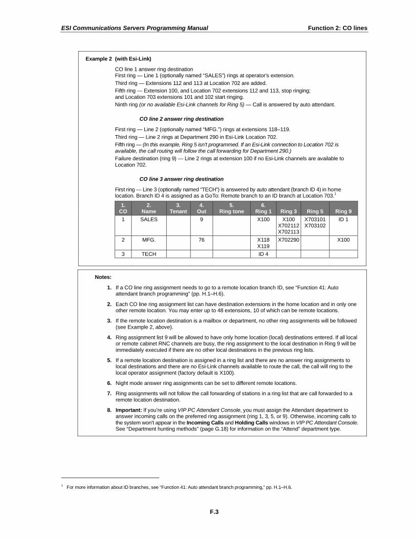
Example 2 (with Esi-Link)
CO line 1 answer ring destination First ring — Line 1 (optionally named “SALES”) rings at operator’s extension.
Third ring — Extensions 112 and 113 at Location 702 are added.
Fifth ring — Extension 100, and Location 702 extensions 112 and 113, stop ringing;
and Location 703 extensions 101 and 102 start ringing.
Ninth ring (or no available Esi-Link channels for Ring 5) — Call is answered by auto attendant.
CO line 2 answer ring destination
First ring — Line 2 (optionally named “MFG.”) rings at extensions 118–119.
Third ring — Line 2 rings at Department 290 in Esi-Link Location 702.
Fifth ring — (In this example, Ring 5 isn’t programmed. If an Esi-Link connection to Location 702 is
available, the call routing will follow the call forwarding for Department 290.)
Failure destination (ring 9) — Line 2 rings at extension 100 if no Esi-Link channels are available to
Location 702.
CO line 3 answer ring destination
First ring — Line 3 (optionally named “TECH”) is answered by auto attendant (branch ID 4) in home location. Branch ID 4 is assigned as a GoTo: Remote branch to an ID branch at Location 703.
1
1. CO
2. Name
3. Tenant
4. Out
5. Ring tone
6. Ring 1
Ring 3
Ring 5
Ring 9
1 SALES 9 X100 X100 X702112 X702113
X703101 X703102
ID 1
2 MFG. 76 X118
X119
X702290 X100
3 TECH ID 4
Notes:
1. If a CO line ring assignment needs to go to a remote location branch ID, see “Function 41: Auto attendant branch programming” (pp. H.1–H.6).
2. Each CO line ring assignment list can have destination extensions in the home location and in only one other remote location. You may enter up to 48 extensions, 10 of which can be remote locations.
3. If the remote location destination is a mailbox or department, no other ring assignments will be followed
(see Example 2, above).
4. Ring assignment list 9 will be allowed to have only home location (local) destinations entered. If all local or remote cabinet RNC channels are busy, the ring assignment to the local destination in Ring 9 will be
immediately executed if there are no other local destinations in the previous ring lists.
5. If a remote location destination is assigned in a ring list and there are no answer ring assignments to local destinations and there are no Esi-Link channels available to route the call, the call will ring to the
local operator assignment (factory default is X100).
6. Night mode answer ring assignments can be set to different remote locations.
7. Ring assignments will not follow the call forwarding of stations in a ring list that are call forwarded to a
remote location destination.
8. Important: If you’re using VIP PC Attendant Console, you must assign the Attendant department to answer incoming calls on the preferred ring assignment (ring 1, 3, 5, or 9). Otherwise, incoming calls to
the system won’t appear in the Incoming Calls and Holding Calls windows in VIP PC Attendant Console. See “Department hunting methods” (page G.18) for information on the “Attend” department type.
1 For more information about ID branches, see “Function 41: Auto attendant branch programming,” pp. H.1–H.6.

ESI Communications Servers Programming Manual Function 2: CO lines
F.4
The steps for programming CO lines throughout Function 21 are:
1. Choose the CO lines to program.
2. Name the CO lines. This is optional; to retain the default values — “Line 1,” “Line 2,” and so on — press #.
Optional naming of the CO lines
During this step, you optionally can name the CO lines you’re programming. Each name can contain up to 10 alphanumeric characters. If you press # while performing this step, the default
names (e.g., “Line 1,” “Line 2,” etc.) will be retained.
If you select multiple CO lines to program, the name field will be left blank; at this point, you can either press # to keep all of the lines’ default names or, by entering a name, assign the same
name to all selected CO lines.
To change an already programmed name to the default value, press HOLD to delete the name and then press # while the field is blank. This restores the default values for all selected lines.
If used in conjunction with Caller ID, this feature causes the Caller ID name to appear on the first line, and the line name to appear on the second line, until the call is answered; then the phone number will appear for five seconds. After that, a call timer appears on the display. If Caller ID isn’t
enabled, the CO name will appear on the top line of the display. In either case, the third line of a 48-Key Feature Phone’s display shows line usage.
Default: Line numbers.
3. Follow the remaining steps (as described herein) that are specific to the function you’re programming — Function 211 (analog CO line programming), Function 2121 (T1 CO line programming) or Function 2131 (PRI CO line programming).

ESI Communications Servers Programming Manual Function 2: CO lines
F.5
Function 211: Analog CO line programming
This function allows you to program the analog COs for both day and night mode. You can select the trunk
groups and ring assignments for a group of COs or individual lines. The steps are:
1. Choose CO lines to program.
2. Name the CO lines (optional).
3. Assign the CO lines’ tenant1.
4. Assign outbound CO line groups.
5. Assign distinctive CO ring tone.
6. Assign answer rings.
1. Choose CO lines to program
During this step, you use the programmable keys to represent CO lines. Select lines to be programmed by pressing one or more of the programmable keys. Press the scroll keys ( or ) to “page” in increments appropriate for the port card configuration.
2 The display will indicate which CO lines the programmable
keys currently represent.
Software will identify the port card type installed in each slot. The display will show the following information: the first line will show the port card number, the type of card, the COs available to program and a D or N for day or night mode. The second line will show the CO currently selected and the circuit that is being programmed. The appropriate programmable feature key lights will light red to indicate the lines available to program.
If the port card in the first slot is a 612, the display will be:
PC1 612 1-6 D
CO1 CIRCUIT 1 >
If the port card in the third slot is a 684, the display will be:
PC3 684 13-18 N
CO16 CIRCUIT 4 >
In both examples, the first six DSS LEDs glow red. Select the COs to program alike (you can scroll to select the next port card and continue to select COs to be programmed alike) and press the # key to confirm. The LEDs will now glow green.
2. Name the CO lines
This is optional; to retain the default values — “Line 1,” “Line 2,” and so on — press #. (See “Optional naming of the CO lines,” pg. F.4, for more details.)
Note: Naming the CO lines will replace the Caller ID number (if supplied by the provider) on an
incoming call. However, the number will appear after the call is answered.
1 If tenant service is enabled in Function 169 (see page E.10).
2 If all cards support only analog lines, the lines will appear in six-line increments: 1–6, 7–12, 13–18, etc. If at least one DLC is installed, the
numbering plan will be different.

ESI Communications Servers Programming Manual Function 2: CO lines
F.6
3. Assign each CO line’s tenant
The tenant parameter1 is used here to have each CO line follow the day/night mode of the tenant to which it’s
assigned. The day/night mode can be changed either by the day/night programmable feature key on a station in the same tenant as the CO or by the day/night table assigned for that tenant in Function 43 (see page H.7).
4. Assign outbound CO line groups
CO lines can be grouped for outbound, pooled access into one of eight line groups: 9, 8, 71, 72, 73, 74, 75 or 76.
Note: A line can only be in one line group or designated as a private line.
Select the line group and press the # key to confirm. Outgoing calls will be assigned from the highest CO to the lowest available. Or, to delete the line group number (whereupon the line can only receive inbound CO line calls), press HOLD. Default: 9 (i.e., all CO lines in Group 9).
Note: To assign a CO line for incoming traffic only, don’t enter a CO line group here.
Private line
You can designate a line as a private line by entering an extension number, instead of a line group number, in this step. The line is then programmed as outlined in the following explanation, giving the private line great flexibility for handling call routing.
Notes: Private lines don’t follow ARS.2
A private line can be assigned only to an ESI phone (desktop model or Cordless Handset). A line key must be programmed on the phone to access the line for outgoing calls. If the line key is programmed on another phone, it can be used ONLY for incoming access (it may also serve just
as a purely visual indicator).
5. Assign a distinctive CO ring tone
A distinctive CO ring tone overrides the station ring tone for incoming calls. Select one of the six available tones to enable the feature, or select NORMAL to disable the feature. Range: 1–6 and normal (disabled). Default: Normal (disabled).
1 To view and change the tenant number, you must first have enabled tenant service in Function 169 (see page E.10).
2 Automatic route selection.

ESI Communications Servers Programming Manual Function 2: CO lines
F.7
6. Assign answer rings
Lines can be directed to be answered at up to 481 extensions, a department, a mailbox or an auto
attendant branch ID (see “Auto attendant programming,” page H.1). The destination can be set to add or drop extensions, departments, mailboxes or ID branches if ringing continues due to no answer.
Example: First ring — Line 1 will ring at the operator's extension. Third ring — Extensions 112 and 113 are added.
Fifth ring — The operator's station is dropped from ringing. Ninth ring — The call will be answered by the auto attendant.
CO Name Tenant Out Ring
tone
Ring 1 Ring 3 Ring 5 Ring 9
1 9 100
100
112 113
112
113
ID1
Once you have programmed all desired CO lines for day mode, repeat the programming steps for all desired CO lines for night mode. Default: Answer on ring 1 with ID1 (main greeting) in both day and night modes.
Example: To have after hours calls directed to a general delivery mailbox, program the system as follows. During night mode, Line 1 (and other lines to be programmed alike) will be answered immediately
by MB 301 (a guest mailbox set up for general delivery). The personal greeting for MB 301 might be:
“Hello, thank you for calling ABC Company. Our offices are closed. Our normal business hours are 8 to 5 Monday through Friday. Please leave a message at the tone and your call will be returned when we resume normal business hours.”
A Virtual Mailbox Key programmed at the operator’s phone will allow easy pick-up of calls left during the night.
Night mode
CO Name Tenant Out Ring tone
Ring 1 Ring 3 Ring 5 Ring 9
1 MB301
Note: The CO line groups, tenant, and ring tone parameters aren’t programmable from night mode.
1 Except on the ESI-100, where the limit is 32.

ESI Communications Servers Programming Manual Function 2: CO lines
F.8
Using the DLC and DLC12 for T1 and PRI: An overview (Functions 212 through 2135)
The DLC and DLC12 port cards are plug-in designs that can be installed in any of the available card slots on the system highway. Each card provides either a T1 interface supporting 24 DS0 channels and 12 digital stations or an ISDN PRI interface supporting 23 B (bearer) channels, one D (datalink) channel and 12 digital stations. A jumper (labeled J3) on the DLC or DLC12 must be plugged horizontally onto pins 7 and 8 of J3 to enable ISDN PRI functions. For more information, refer to the DLC12 Configuration Instructions (ESI part
#0450-0791).
Notes: If jumper J3 is removed from or added to an already installed DLC or DLC12, all CO line programming will return to system defaults, and all of the systems’ stations will revert to default settings for station options (hands-free answer, call waiting, background announce, monitor mode, outside dialtone
preference, headset operation, etc.).
Mailbox 598 is a special-purpose mailbox for monitoring T1/PRI alarms. Whenever the system detects a severe T1 or PRI alarm, it will store a message in this mailbox. You also can program outdial notification
(in mailbox settings) to alert someone when the system detects such an alarm.
Function 212: DLC and DLC12 programming for T1
This function allows you to program the trunks and line parameters for the DLC or DLC12. The system will identify the number of DLCs and DLC12s installed (one to six) and allow you to scroll through the 24 channels on each port card.
T1 PROGRAMMING
Function 2121: CO line programming
Note: Set trunk type emulation, as explained below, before proceeding to name any line.
The first line of the display will show the port card number, the type of card, the COs available to program and a D or N for day or night mode. The second line will show the CO currently selected and the circuit that is being programmed. If multiple COs are selected, then the last CO selected is displayed. All DSS LEDs will glow red until selected for programming.
1. Choose CO lines to program
You can select from the first set of 24 COs on the first card. Scrolling again will allow you to select the 24 COs on a second card if one is installed. If there is only one DLC or DLC12 installed, then scrolling will return you to the first 24 COs.
Note: A 24-Key Feature Phone will display only the card’s first 12 COs; scroll to view the next 12 on the
same card. Scroll again to see the first 12 COs on the second card (if installed).
Select the COs to program alike and press # to confirm. The LED will glow green and then, after a CO is programmed, the LED will glow amber. The programming of the first CO should default forward for the remaining COs selected. After the selected COs are programmed, the LED will glow amber.
For example: if the port card in the third slot is an DLC12 card, the display will be:
PC3 DLC12 13-36D
CO22 CIRCUIT 10>
(Continued)

ESI Communications Servers Programming Manual Function 2: CO lines
F.9
2. Select trunk type emulation
Use the scroll keys to select the trunk type emulation: either E&M DNIS/DID, E&M, LOOP START or GROUND START. Press # to confirm. (Default is E&M DNIS/DID.)
TRUNK EMULATION
E&M DNIS/DID >
If you select LOOP START or GROUND START, continue with the outbound CO line groups and answer ring assignment. If you select E&M DNIS/DID, the lines are routed to the DNIS/DID table.
1 After the E&M programming is
complete, name the CO lines and then select the outbound CO line groups. If you select E&M, the lines are routed to the answer ring assignment. After the E&M programming is
complete, name the CO lines and then select the outbound CO line groups and the answer ring assignment.
To complete the programming of the E&M trunks selected:
1. Use the scroll keys to select the outgoing signal type — WINK START, IMMEDIATE START or DIAL TONE START. Press # to confirm. Default: WINK START.
OUTGOING SIGNAL
DIAL TONE START>
2. Use the scroll keys to select the incoming signal type — either WINK START or IMMEDIATE START. Press # to confirm. Default: WINK START.
INCOMING SIGNAL
IMMEDIATE START>
3. Use the scroll keys to select the trunk mode — 2-WAY TRAFFIC, INBOUND ONLY or OUTBOUND ONLY. Press # to confirm. Default: 2-WAY TRAFFIC.
TRUNK MODE
2-WAY TRAFFIC >
4. Use the scroll keys to set dial tone transmit to either OFF or ON. Press # to confirm.
Default: OFF.
DIAL TONE TRANS.
OFF >
5. Use the scroll keys to set ringback transmission to either OFF or ON. Press # to confirm.
Default: OFF.
RINGBACK TRANS.
OFF >
3. Name the CO lines
This is optional; to retain the default values, press #. (See “Optional naming of the CO lines,” pg. F.4, for more details.)
(Continued)
1 Also if E&M DNIS/DID is selected: Caller ID over T1 is not supported.

ESI Communications Servers Programming Manual Function 2: CO lines
F.10
4. Assign outbound CO line groups
Select the line group — 9, 8, 71, 72, 73, 74, 75, or 76 — and press # to confirm. Outgoing calls will be assigned from the highest CO to the lowest available. Default is 9. (You can designate a private line by entering an extension number instead of a line group in this step.)
Note: To assign a CO line for incoming traffic only, don’t enter a CO line group here.
5. Assign distinctive CO ring tone
A distinctive CO ring tone overrides the station ring tone for incoming calls. Select one of the six available tones to enable the feature, or select NORMAL to disable the feature. Range: 1–6 and normal (disabled). Default: Normal (disabled).
6. Make answer ring assignments
Note: Ring assignments don’t apply to E&M DID. See Function 224 (pages F.19–F.20) for translation table.
Lines can be programmed with four different ring assignments — Ring 1, Ring 3, Ring 5 and Ring 9.
Each ring count can be programmed for up to 481 extensions, a department, a mailbox or an auto
attendant branch ID. E&M lines must be answered by the auto attendant under Ring 1.
After all lines are programmed for day mode, the steps are repeated for night mode.
Function 2122: T1 frame format and line coding
Use the scroll keys to select the frame format and line coding — either ESF/B8ZS, SF/AMI, ESF/AMI or SF/B8ZS. Press # to confirm. Default is ESF/B8ZS.
P-CARD 3 DLC12
FF/LC ESF/B8ZS >
If a second DLC or DLC12 is installed, the system will alternate to the next port card. Use the scroll keys to select the frame format and line coding. Press # to confirm.
Function 2123: Line build-out
Line compensation (or line build-out) is provided, as necessary, between the CSU and SmartJack and the ESI Communications Server. This function allows you to adjust the line build-out of the card. The level programmed depends on the application (CSU or DSX-1) indicated in the following table:
Level CSU line build-out DSX-1 line build-out
1 0 dB 0 to 133 feet
2 N/A 133 to 266 feet
3 N/A 266 to 399 feet
4 N/A 399 to 533 feet
5 N/A 533 to 655 feet
6 -7.5 dB N/A
7 -15 dB N/A
8 -22.5 dB N/A
Use the scroll keys to select the line build-out and press # to confirm. Default is 1.
If a second card is installed, the system will alternate to the next port card. Select the line build-out with the scroll key. Press # to confirm.
1 Except on the ESI-100, where the limit is 32.

ESI Communications Servers Programming Manual Function 2: CO lines
F.11
Function 2124: CSU emulation
Use the scroll keys to toggle between enabled and disabled. Default: Off. If there is no external CSU, the CSU emulation setting should be set to On but the remaining options should be left at the default setting of Off. When CSU emulation is enabled, the following test options will be available and should be used only at the request of the carrier.
Test option* Description Options Default
ATT PRF Loopback test per AT&T spec 62411 for performance assessments, sent to the carrier on ESF trunks only.
On/Off Off
ANSI PRM Loopback test per ANSI spec T1.403 for performance assessments,
sent to the carrier on ESF trunks only.
On/Off Off
PLB (Payload loopback.) Accepts signal from the carrier at the chip level, puts it through the framer (de-frames and re-frames signal with data
staying the same) and sends it back to the carrier. Used to determine whether the chip itself is functioning correctly.
On/Off Off
LLB (Line loopback.) Sends the signal back right at the point it enters the
chip before it enters the framer. Helps determine whether the line itself is good.
On/Off Off
NET LLB (Network loopback.) Lets the carrier put the DLC’s CSU into any of the loopback modes.
On/Off Off
* Test options available only when CSU emulation is set to On.
Warning: The default setting is Off for those systems using an external CSU. If there is no external CSU, the CSU Emulation setting should be set to On but the remaining options should be left at the default of Off. Use these other settings ONLY at the request of your carrier or the phone system
manufacturer for testing purposes.
Function 213: DLC and DLC12 (PRI) programming
The options under Function 213 are used to configure the DLC or DLC12 for an ISDN PRI line with 23 B channels and one data channel (24). The first line of the display will indicate the card number and the type of card. The frame format and line coding will default to the ISDN standard of ESF/B8ZS.
One of the main features of PRI is dynamic channel allocation, meaning all telephone numbers on the PRI span can come in over any of the 23 channels. This eliminates the need to forecast call volume for the main published number, because as few as one channel or as many as 23 channels can be occupied at any time by
callers to the main published number. For example, channels 1–20 can be occupied by callers to the main published number while channels 21–23 are open or occupied with DID callers; later, channels 1–15 can be occupied by DID callers while channels 16–23 are open or occupied by callers to the main number.
The components required for programming are CO line programming (Function 2131) and Switch protocol (Function 2134). In addition to the required fields, there are also fields for line build-out (Function 2132), CSU emulation (Function 2133) and DID enable/disable (Function 2135) that typically are left off at default.
Note: Mailbox 598 is a special-purpose mailbox for monitoring T1/PRI alarms. Whenever the system
detects a severe T1 or PRI alarm, it will store a message in this mailbox. You also can program outdial notification (in mailbox settings) to alert someone when the system detects such an alarm.
Function 2131: PRI CO line programming
The 23 voice channels support both inbound and outbound traffic. Answer ring assignments must be assigned for daytime and night routing. This routing will be followed only if DID is disabled. Because of the dynamic channel allocation on PRI, there is no control over the channel any given number rings in on. For
this reason it is recommended that all channels be routed the same. For maximum flexibility, we allow each channel to be selected individually. For example: in some cases, the outbound line group needs to be different or possibly have the first five channels be live-answer, then send the overflow to ID 1.
When performing the CO line programming, remember that there are only 23 channels; the 24th channel is used for signaling, so it does not take up a port and it needs no programming. If the PRI card is in the first slot, the COs will be 1–23 and the next card will start with CO 24.

ESI Communications Servers Programming Manual Function 2: CO lines
F.12
1. Choose CO lines to program
Using the programmable feature keys, select the line keys to be programmed.1 Press # to confirm.
2. Select Dialtone transmit on or off.
Default: Off.
3. Select Ringback transmit on or off.
Default: On.
4. Name the CO lines
This is optional; to retain the default values, press #. (See “Optional naming of the CO lines,” pg. F.4, for more details.)
5. Assign each CO line’s tenant
The tenant parameter2 is used here to have each CO line follow the day/night mode of the tenant to
which it’s assigned. The day/night mode can be changed either by the day/night programmable feature key on a station in the same tenant as the CO or by the day/night table assigned for that tenant in
Function 43 (see page H.7).
6. Assign outbound CO line groups
Enter the CO line group (9, 8, or 71–76).
7. Make answer ring assignments
Lines can be programmed with four different ring assignments — Ring 1, Ring 3, Ring 5 and Ring 9. Each ring count can be programmed for up to 48
3 extensions, a department, a mailbox or an auto
attendant branch ID.
Notes: Ring assignments don’t apply if DID is enabled in Function 2135.
After you program a ring assignment for a department, mailbox or ID branch, no remaining ring
assignments will be required because, upon reaching any of these, the call is considered answered.
Example: Ring 1 Ring 3 Ring 5 Ring 9
X100 X100, X101, X102 ID1 Not used (system won’t
prompt you to program)
8. Repeat if needed for night programming
Repeat steps 1–7 for night programming.
1 If using a 24-Key Feature Phone to program, use the scroll keys to select lines 13–23.
2 To view and change the tenant number, you must first have enabled tenant service in Function 169 (see page E.10).
3 Except on the ESI-100, where the limit is 32.

ESI Communications Servers Programming Manual Function 2: CO lines
F.13
Function 2132: Line build-out
Use the arrow keys to select a value of 1–8 (you can make one selection per installed DLC). Press # to confirm. The level programmed depends on the application (CSU or DSX-1) indicated in this table:
Level CSU line build-out DSX-1 line build-out
1 0 dB 0 to 133 feet
2 N/A 133 to 266 feet
3 N/A 266 to 399 feet
4 N/A 399 to 533 feet
5 N/A 533 to 655 feet
6 -7.5 dB N/A
7 -15 dB N/A
8 -22.5 dB N/A
Default: 1.
Function 2133: CSU Emulation
Use the arrow key to toggle between On and Off. Default: Off.
If there is no external CSU, the CSU Emulation setting should be set to On but the remaining options should be left at the default setting of Off. When CSU emulation is enabled, the following test options will be available and should be used only at the request of the carrier:
• ATT PRF — Loopback test per AT&T spec 62411 for performance assessments, sent to the carrier on ESF trunks only.
• ANSI PRM — Loopback test per ANSI spec T1.403 for performance assessments, sent to the carrier on ESF trunks only.
• PLB (payload loopback) — Accepts signal from the carrier at the chip level, puts it through the framer (de-frames and re-frames signal with data staying the same) and sends it back to the carrier. Used to determine if the chip itself is functioning correctly.
• LLB (line loopback) — Sends the signal back right at the point it enters the chip before it hits the framer. This helps determine if the line itself is good.
• NET LLB (network loopback) lets the carrier put the CSU of the DLC or DLC12 into any of the loopback modes.

ESI Communications Servers Programming Manual Function 2: CO lines
F.14
Function 2134: Switch protocol selection
Use the scroll keys to select from the four switch options for your carrier.
• Nortel — DMS100
• AT&T/Lucent — 5ESS
• National — NI2 – Default
• Siemens — EWSD
Note: Most switches can emulate the various protocols. Please be sure to base your selection on the
protocol being used rather than the actual switch manufacturer. For example, your central office could have a Nortel DMS 100 switch but have the span configured as NI2; in this instance, you would select the option for National/NI2.
Warning: After changing the switch protocol, be sure to finish programming all other remaining options before
exiting programming mode (as needed, press # to accept current entries for function parameters you’re not changing). Then, wait at least four full minutes and power-cycle the system.
Function 2135: DID
With DID enabled, call processing will check first the pilot number table and then the DID table, and route the call accordingly. Any number not found in the pilot number or DID tables (programmed in Functions 224
and 225) will be routed to the DID exception routing. With DID disabled, all calls will follow the routing as programmed in PRI CO line programming (Function 2131).
Default: Disabled.

ESI Communications Servers Programming Manual Function 2: CO lines
F.15
Function 22: Translation table programming
Function 221: Centrex/PBX access code
If the system is to be used behind Centrex or another PBX, you must list the dial access code used to gain access to a CO line from Centrex or the PBX, so that toll restriction can ignore the access code digit(s). Users must dial the access code after accessing a line by either: (a.) Dialing 9, 8, 71, 72, 73, 74, 75 or 76. or (b.) Pressing a line key (if programmed). The access code can be one or two digits — e. g., 9, 81, etc. — and must be programmed for each line group. Default: 0.
Note: You must set the flash duration in Function 151 (page E.3) for the requirements of the host switch.
Function 222: Toll restriction exception tables
The system’s toll restriction is based on outbound calls being defined as either toll calls (i.e., calls in the deny table) or non-toll calls (calls in the allow table). Four tables exist for this purpose:
1. Allow exception table (programmable). Up to 100 entries; no entry can exceed 26 digits. Default: No entries.
2. Deny exception table (programmable). Up to 100 entries; no entry can exceed 26 digits. Default: No entries.
A number listed in the allow exception table — e.g., a branch office or vendor’s location — will be allowed to all stations, regardless of how they’re set in Function 32 (see page G.15). Conversely, a number listed in the
deny exception table (e.g., a “1-900” number) will be denied to all stations.
3. Fixed allow table (not programmable). Default: 1800, 1888, 1877, 1866, 1855, 1844, 1833 and 1822.
4. Fixed deny table (not programmable). Default: 976, 1976, 1xxx976, 900, 1900, 1xxx900, 555, 1555, 1xxx555, 0, 10, 411, 1411 and 11+-digit restriction.
In extension feature authorization (Function 321; see page G.15), each extension is set to be toll-restricted one of two ways: TOLL CALLS = Y (yes) or TOLL CALLS = N (no).
Note: System speed-dial numbers (Function 17; see page E.11) are not affected by toll restriction.
(Continued)

ESI Communications Servers Programming Manual Function 2: CO lines
F.16
If TOLL CALLS = Y (yes) in Function 321 (page G.15), the system checks the number dialed against the Deny Exception table. If the number matches an entry in this table, the call is restricted. Otherwise, it’s allowed.
If TOLL CALLS = N (no) in Function 321 (page G.15):
1. First, the system checks the number dialed against the Allow Exception table. If the number matches an entry in this table, the call is allowed.
Otherwise . . .
2. The number is checked against the Deny Exception table. If the number matches an entry in this table, the call is restricted. Otherwise . . .
3. The number is checked against the Fixed Allow table. If the number matches an entry in this table, the call is allowed. Otherwise . . .
4. The number is checked against the Fixed Deny table.
If the number matches an entry in this table, the call is denied. Otherwise . . .
5. The call is allowed.
How toll restriction works
As a number is dialed (or a speed-dial key is pressed), the system compares the number dialed, starting with the first digit, until a match is found in one of the toll-restriction tables, in the order described above under “If TOLL CALLS = N (no).” If no match is found, the default is to allow the call.
Example: Extension 101 is set with TOLL CALLS = N in Function 321. The user dials 1 5 5 5 1 2 1 2. The system finds the first digits in the number dialed match the entry 1 5 5 5 in the Fixed Deny table.
Since extension 101 isn’t allowed toll calls, the call will be restricted (blocked).
(Continued)

ESI Communications Servers Programming Manual Function 2: CO lines
F.17
How to program the allow and deny exception tables
1. Select the table to which you’ll be adding or changing entries, Allow or Deny.
2. Enter each number pattern that will be allowed or denied, pressing # after each pattern. To delete an entry, use the scroll keys to select the number and press HOLD to delete.
Example: For “1-900,” enter 1 9 0 0 #.
Notes: Press MUTE/DND to insert a “wild card” digit. A “wild card” digit is needed only when
followed by more numbers; e.g., to allow/deny 1-555, enter just 1 5 5 5 # — however, to allow/deny all “1+” area codes and 555, enter 1 X X X 5 5 5 # (where X indicates a pressing of MUTE/DND).
If a number that’s already entered in one table is entered in the other table, this will automatically delete the number from the first table. For example: • If 8 9 0 is an entry in the Deny Exception table . . .
• . . . and, later, 8 9 0 is entered in the Allow Exception table . . . • . . . then 8 9 0 will be automatically deleted from the Deny Exception table.
Warning:Do not include system line access codes (9, 8, or 71–76) in any of the toll restriction entries.
3. After the last number, enter # # to end the list. The system will apply the numbers you enter to their most significant digit.
Example: Entering 1 5 0 5 into the deny exception table tells the system to deny all “1+” calls to
area code 505. But entering 1 5 0 5 5 5 5 8 7 8 7 into the table tells the system to deny “1+” calls specifically to (505) 555-8787 while allowing other “1+505” calls.
To allow information calls, enter into the allow table: 411, 1411, 5551212, 1XXX5551212 (where X is a wild card digit, entered by using MUTE/DND).
Default: None.

ESI Communications Servers Programming Manual Function 2: CO lines
F.18
Function 223: Automatic route selection (ARS)1
Within an ESI Communications Server, route selection is normally accomplished by assigning lines to line
groups (9, 8, or 71–76). The user then manually selects the line group for the type of call to be made. Typically, the same carrier handles both local and long distance calls so the user will only have to select an alternate group (71–76) for rare occasions.
If DLCs or DLC12s are used, different line groups may be required to allow the user to access the local loops (via regular loop lines or T1) and long distance trunks (via T1). ARS is designed to eliminate the need for the user to manually select a line group when calling in this situation (such as 9 for local and 8 for LD).
If ARS has been enabled in Function 223, the system will not connect to a line immediately when the user dials 9 (or goes off-hook with outside dial tone preference enable). Instead, the system will “play” outside dial
tone to the user, store the digits dialed, and check the toll restriction tables and if allowed, then determine the ARS call type: Local (9), LD (8), or other (line groups assigned in tables 3–10).
If the call is determined to be “Local,” it will then be dialed on a line in line group 9. If the call is determined to be an “LD” call, it will be placed on a line programmed in line group 8. Therefore, if ARS is to be used, local lines must have been programmed in line group 9 and lines for long distance calls must have been programmed in line group 8 in CO line programming (Function 21).
In addition, a list of area codes or numbers can be created that will be dialed on the programmed line group and Other Common Carrier code
2.
Here’s an example:
Table Line group(s) OCC Definition
1 9 7 or 10 digits, information
2 8 1+, 0+, 01+, 011+, or 101XXXX
[3–10] 9, 8, 71–76 101XXX 1+XXX, 1+YYY, etc.
(Continued)
1 A digital line card (DLC or DLC12) is not necessary for ARS.
2 A code (e.g., 1010) to be dialed before the actual number, often to connect with a specific long-distance provider.
Fixed

ESI Communications Servers Programming Manual Function 2: CO lines
F.19
Programming Function 223 ARS
1. Enable/disable ARS (default is DISABLED).
2. Select the ARS table to program (3–10).
3. Use the scroll key to select the line group.
4. Enter Other Common Carrier numbers.
5. Enter up to 100 numbers for the table, separating each number by #.
Example: For “1-976,” enter 1 9 7 6 #.
Note: Press MUTE/DND to insert a “wild card” digit. The Hold key will delete an entry.
Warning: Do not include the system’s line access codes (9, 8, or 71–76) in this table.
The system will apply the numbers you enter to their most significant digit.
Examples: Entering 1 5 0 5 into the table tells the system to place all “1+” calls to area code 505 to the line
group and Other Common Carrier listed.
Entering 1 5 0 5 5 5 5 8 7 8 7 into the table tells the system to place “1+” calls specifically to (505)
555-8787 to the line group and Other Common Carrier listed while other “1+505” calls will follow regular LD routing to line group 8.
After the last number, enter # # to end the list. Enter another list or press # to exit.
Note: Toll restriction, as set in Functions 222 and 32, will be applied to calls before released.
Function 224: DID and DNIS translation table
A translation table is programmed to translate DID or DNIS routing numbers to the corresponding ID (ID), mailbox (MB) extension (EXT) or department with both day and night destinations. An ESI Communications Server supports up to four-digit DID and DNIS/ANI. Each model has a maximum number of entries that can be programmed into the table (multiple numbers programmed to the same destinations); see “Translation tables” in “System capacities” (page B.1). An entry for exceptions is provided and can be programmed for an ID (ID), mailbox (MB) or extension or department (X). Default: First extension in the system.
DID/DNIS TABLE
DID/DNIS #:3352>
DID/DNIS TABLE
EXCEPTION: >
(Continued)

ESI Communications Servers Programming Manual Function 2: CO lines
F.20
To program the DID and DNIS translation table:
1. Either enter the DNIS or DID number or use the scroll keys to select a previously programmed number or exception.
Notes: Pressing the right scroll key will start with a blank number field for entry and continue through all
previously programmed numbers, ending with the exception entry (continuing to scroll will start over the blank entry). Pressing the left scroll key will start with the exception entry, continue in reverse order with previously programmed numbers and end with the blank number entry (continuing to
scroll will start over with the exception entry). Pressing HOLD will delete an entry.
2. Press the # key. The system will prompt you to enter a name for this DID; the name will appear on the bottom line of the display of a station using the line.
3. Enter the desired name (see “Entering alphanumeric characters,” page D.2).
Note: If a name is entered for a DID and there is an inbound CO call, the DID name (instead of the
Caller ID number) will be displayed until the call is answered.
4. Press the # key. The system will prompt you for the day mode call routing.
5. Use the scroll keys to select whether you’re routing to a branch (ID), mailbox (MB), or extension or department (EXT); then enter the number. Here are two examples, based on the example table below:
DID/DNIS #: 3352
DAY ID: 12 >
EXCEPTION:
DAY EXT: 100 >
6. Press the # key. The system will prompt you for the night mode call routing.
7. Use the scroll keys to select whether you’re routing to a branch (ID), mailbox (MB), or extension or
department (EXT); then enter the number. Here are two examples, based on the example table below:
DID/DNIS #: 3352
NIGHT MB: 400 >
EXCEPTION:
NIGHT EXT: 100 >
8. Press the # key to finish.
Note: The HOLD key will delete an entry.
Here’s an example:
DID or DNIS Name Day translation Night translation
3578 X105 X105
3624 X290 MB410
3352 ID12 MB400
Exceptions Operator (X100) Operator (X100)

ESI Communications Servers Programming Manual Function 2: CO lines
F.21
Function 225: Pilot number translation table
Note: This feature is accessible only if Function 2135 (page F.14) is enabled.
Every call on a PRI span is sent with the called number in the setup message. This means you can determine whether to use a number as a pilot number or as a DID number. Pilot numbers are a means of routing a company’s primary published phone number differently from a DID. Each ESI Communications Server has a different capacity for pilot entries, each with its own answer ring assignment; see “Translation tables” in “System capacities” (page B.1). This is important, because the dynamic channel allocation prevents you from
routing based on channel.
Pilot numbers can be routed to an ID branch, department, extension or mailbox. This varies from DIDs in that, when a DID number is routed to an extension, it is considered answered and follows the busy/ no-answer routing of the extension; but, with pilot numbers, the call will be routed to the extensions for live answer for the designated number of rings, then can be routed to an ID branch in the event of busy/no-answer. If the PRI span is used for outgoing calls, pilot table entry 1 is used for outgoing Caller ID, as well. Because of this, pilot number entry 1 should always be programmed with 10 digits.
Note: An extension’s Caller ID number setting (see “Function 31: Extension definition and routing,” beginning
on page G.2) overrides the pilot number’s Caller ID information set here.
Max Channels value
Max Channels is the maximum number of channels that can be used simultaneously for incoming calls to a particular pilot number. Incoming calls to that pilot number are rejected (CO plays busy signal) when the Max Channels value is exceeded for the pilot number. Max Channels is applicable only to incoming calls.
Notes: This setting works only if the digits in the pilot number entry exactly match the digits that the PRI
carrier sends in its messaging.
The sum of maximum channels of any PRI pilot number must not exceed 23.
To program the pilot number translation table:
1. Use the scroll keys to select the entry number.
2. Enter the pilot number, two to 10 digits in length.1
3. Enter the name for the pilot number.
4. Enter the maximum channels allowed for this pilot number. Range: 1–23. Default: 23.
5. Enter the distinctive CO ring tone for this pilot number. Range: 1–6 or normal (disabled). Default: Normal (disabled).
6. Set answer ring assignments for both day and night modes.
Note: For programming information, see step 7 in Function 2131 (page F.12).
7. Repeat steps 1–6 for the remaining pilot numbers.
Example: Day Night
Entry no.
Pilot no. Name Max chs.
Ring tone
Ring 1
Ring 3
Ring 5
Ring 9
Ring 1
Ring 3
Ring 5
Ring 9
1 2145551452 ABC Co. 16 X100 X100, X101
X101 ID1 MB100 MB100 MB100 MB100
2 1245 Private line 1 X106 X106 MB106 MB106 MB106 MB106
3
4
5
1 If the carrier sends a pilot number with fewer than 10 digits, the system will use only the rightmost digits of the called number.

ESI Communications Servers Programming Manual Function 2: CO lines
F.22
Tenant service and pilot numbers
If tenant service is enabled, the first pilot number (i.e., entry 1) is used for tenant 1’s outgoing Caller ID, and so on through entry 8 for tenant 8’s outgoing Caller ID. When a station (or the station’s voice mailbox) originates an outgoing call via a PRI channel, the pilot number of the station’s tenant will be used for that call’s outgoing Caller ID. Also: any auto attendant outdial branches that originate from branch ID 1 will use Caller ID for tenant 1, and so on through branch ID 8 for tenant 8.
If more than one PRI circuits (port cards) are installed
Example A: Pilot number to either PRI port card
Where there are multiple PRI port cards installed, a pilot number can have calls directed to it from one or more of the cards. The Max Channels value entered sets the maximum number of channels the pilot number will use for each PRI port card. Therefore, the Max Channels value can’t exceed 23 for each pilot number, even if there are three PRI port cards installed.
A customer has two PRI port cards (46 channels). Both PRI port cards handle calls to the main pilot
number (972 555-3200) and Customer Service department (972 555-3300). Up to 32 channels can be used for calls to the main number, and up to 10 channels can be used for Customer Service calls. Since there are two PRIs, the Max Channels value to assign is half of the actual number of channels for each pilot number.
In Function 225, pilot number 972 555-3200 will be assigned a Max Channels value of 16, and pilot number 972 555-3300 will be assigned a Max Channels value of 5. This is because 16 Max Channels x 2 PRIs = 32 actual
maximum channels for pilot number 972 555-3200. Similarly, pilot number 972 555-3300 will have 10 actual maximum channels.
Example B: Pilot number to one PRI
There can be instances wherein one pilot number takes incoming calls from one PRI and another pilot number is used to take calls from the second PRI. In this case, don’t divide the maximum channels by the number of PRIs installed.
A customer has two PRI port cards (46 channels). The first PRI has a toll-free pilot number (800 555-4141) that directs incoming calls to the Customer Service department, and can use all 23 channels of that PRI. The second PRI uses a pilot number to direct calls to the main business number (214 555-5678); up to 12 channels can be used for that pilot number.
Each of the pilot numbers are assigned to individual PRIs; so, in Function 225, pilot number 800 555-4141 will be assigned a Max Channels value of 23, and pilot number 214 555-5678 will be assigned a Max Channels value of 12.
Entry number
Pilot number
Max Channels
1 9725553200 16
2 9725553300 5
Entry number
Pilot number
Max Channels
1 8005554141 23
2 2145555678 12
ESI Communications Servers Programming Manual Function 2: CO lines
F.23
Function 23: CO line parameters
Function 231: System CO line receive volume
Many variables can affect the volume of the CO lines. Weak lines can reduce the ESI Communications Server’s ability to properly detect DTMF dialed by an outside caller. Conversely, “hot” lines can cause DTMF distortion and/or increase the opportunity for message talk-off (i. e., messages being cut off before completion). Ideally, a message recorded from an outside call has the same playback volume as the system prompts. This function can be used to adjust the gain of the receive volume of the CO lines system-wide. Range: 0–14 (lowest to highest gain, respectively). Default: 10.
Function 232: Line disconnect
You can set the lines to detect the open loop interval (if available from the CO) and disconnect more quickly. This will also allow the system to:
• Drop abandoned calls from hold.
• Reduce the opportunity for abandoned calls to be transferred by the auto attendant
• Reduce the possibility that abandoned calls could create messages that are either silent or contain CO-generated tones.
Since open loop intervals generated by the CO may vary in duration, use this function to program the system to less than or equal to the CO open loop interval. If this programmed value is set unnecessarily low, the system may falsely interpret static or a momentary loop break as an open loop and disconnect a caller on
hold or in the process of leaving a message. If this value is set too high, the system may not detect a valid open loop signal for fastest call processing. Range: 1–255 (10–2,550 ms) (or 0 to turn off open loop detect). Default: 6 (60ms).
Function 233: T1 line receive volume
Many variables can affect the volume of the T1 lines. Different volume levels may be required when
connecting a DLC or DLC12, depending on the signal level of the T1. The volume level can be adjusted by increasing or decreasing the digital pad setting. By default, the digital pad setting is –2 db. Changes to the setting are in 2-db increments.
Example: If calls received at the extension have low volume levels, the pad level for that T1 circuit can be adjusted to increase the volume. Select the circuit to adjust by pressing the appropriate programmable feature key
and press # to confirm. Use the scroll keys to select the appropriate db level and press # to confirm.
(Continued)

ESI Communications Servers Programming Manual Function 2: CO lines
F.24
Programming a circuit
To program a circuit, select the appropriate programmable feature key and press # to confirm. You can select one or all of the 24 T1 channels.
1 If multiple DLCs or DLC12s are installed, use the scroll keys to
select channels from the additional cards.
PC3 DLC12 13-36
CO22 CIRCUIT 10>
After selecting the COs to program, use the scroll keys to select the new level of gain or loss in db. Press # to confirm. Select additional circuits to adjust and program as above.
RECEIVE VOLUME
LINE COMP -28DB>
Range: -28 db to 6 db (lowest to highest gain, respectively). Default: -6 db.
Function 234: PRI receive volume
Many variables can affect the volume of PRI lines. Different volume levels may be required when connecting a DLC or DLC12, depending on the signal level of the PRI line. The volume level can be adjusted by increasing or decreasing the setting in this function. By default, the setting is –6 dB; changes to the setting are in 2-dB increments.
Example: If calls received at the extension have low volume levels, you can adjust that PRI circuit’s pad level to increase the volume. Select the circuit to adjust by pressing the appropriate programmable feature key
and press # to confirm. Use the scroll keys to select the appropriate dB level and press # to confirm.
Programming a circuit
To program a circuit, select the appropriate programmable feature key and press the # key to confirm. You can select the 23 CO lines
1 on the first DLC or DLC12. Scrolling again will allow you to select the 23 COs
on a second DLC or DLC12 if it’s installed.
PC3 PRI 13-36
CO22 CIRCUIT 10>
After selecting the COs to program, use the scroll keys to select the new level of gain or loss in dB. Press # to confirm. Select additional circuits to adjust and program as above.
RECEIVE VOLUME
LINE COMP -28DB>
Range: -28 dB to 6 dB (lowest to highest gain, respectively). Default: -6 dB.
1 This is the case if you’re using a 48-Key Feature Phone to program. If you’re using a 24-Key Feature Phone to program, only the first 12 channels
will appear initially. Use the scroll keys to program channels 13–24 (T1) or 13–23 (PRI).

ESI Communications Servers Programming Manual Function 2: CO lines
F.25
Function 24: Caller ID
This function activates the Caller ID capability in an ESI Communications Server — if the customer has ordered Caller ID service from the Telco. The system will display the caller’s name (or “out-of-area,” etc.) for incoming calls or messages (or show the Caller ID number if the CO only provides a number). Default: Disabled.
Esi-Dex and auto callback — This is accomplished by pressing REDIAL or ESI-DEX either during message playback or after an Esi-Dex search. Caller ID numbers received from the CO are 10 digits long (and include the area codes for local calls). In auto callback, the system assumes all calls are to be long distance and will automatically add a “1” prefix to the 10 digits to be dialed.
A table of local area codes can be programmed to indicate that calls to those area codes that are to be dialed as local calls. Select one of the following two types of local dialing for each area code entered:
• Local 7 — Local calls that can be dialed only as seven-digit numbers (the system strips the area code before dialing and will not add a “1” prefix).
• Local 10 — Local calls that can be dialed only as 10-digit numbers (the system will not add a “1” prefix).
Maximum area code entries: 16.
For an area code that can be called as a long distance number (with a “1” prefix) and as a local number (10 digits without a prefix), decide which case is the more prevalent and then add to or exclude from the area codes
exception list accordingly. Thus, some of these calls must be made manually.
Notes: Since the Caller ID information is transmitted from the CO during the silence between the first and second rings, enabling this feature will delay the answer of inbound calls until the second ring.
ESI Caller ID works with the standard ring cycle — two seconds on, four seconds off.
Analog stations cannot use the auto-callback feature.

ESI Communications Servers Programming Manual Function 3: Extension programming
G.1
Function 3: Extension programming
This section provides programming for extensions and department groups.
Important: Where any gray shading (■) appears in an example, it represents values either unavailable to the function
or unused in the particular example.
Function 30: Station move
This feature allows the Installer or Administrator to exchange the extension numbers of two extensions. It is used only for exchanging extensions — not guest mailboxes or departments.
Important: Before you use this function on two extensions, make sure they’re both idle at the time.
Along with the extension numbers, this function also will exchange the following parameters (depending on station type):
• Extension name and other assignments (including of the Operator to extension 0 from Functions 31 and 32).
• Mailbox information (personal greeting, notification, schedules).
• Programmable feature keys.
• Personal Dex.
Function 30 has the following limitations:
• Mailboxes cannot be exchanged. Instead, use Function 34 (flexible number assignment; see page G.25).
• Both extensions must be of the same “type” — i.e.., analog to analog, digital to digital, IP to IP — as shown in the following table:
From . . . To . . . Function 30 allowed?
Digital phone Digital phone Yes
Analog extension Analog extension Yes
IP Phone (local or remote) IP Phone (local or remote) Yes
Digital phone Analog extension No1
IP Phone (local or remote) Analog extension No
IP Phone (local or remote) Digital phone No
Fax, modem, door, ringer, server,
RFID Reader, SIP station, VIP Softphone
Any type of phone No
To use this feature:
1. Enter Installer programming through a Digital or IP Feature Phone and go to Function 30.
2. Enter the first extension and press #.
STATION MOVE
1ST EXT: 1044
3. Enter the second extension and then press #.
X1044 J SMITH
2ND EXT: 1056
(Continued)
1 You must use Function 34 (see page G.25) to change the numbers of these types of extensions.
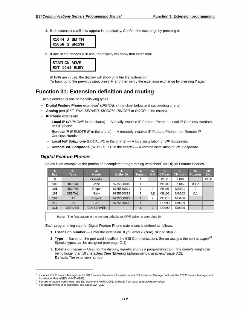
ESI Communications Servers Programming Manual Function 3: Extension programming
G.2
4. Both extensions will now appear in the display. Confirm the exchange by pressing #.
X1044 J SMITH
X1056 S BROWN
5. If one of the phones is in use, the display will show that extension:
STATION MOVE
EXT 1044 BUSY
(If both are in use, the display will show only the first extension.) To back up to the previous step, press and then re-try the extension exchange by pressing # again.
Function 31: Extension definition and routing
Each extension is one of the following types.
• Digital Feature Phone extension1 (DIGITAL in the chart below and succeeding charts).
• Analog port (EXT, FAX, SERVER, MODEM, RINGER or DOOR in the charts).
• IP Phone extension:
– Local IP (IP PHONE in the charts) — A locally installed IP Feature Phone II, Local IP Cordless Handset, or SIP phone.
– Remote IP (REMOTE IP in the charts) — A remotely installed IP Feature Phone II, or Remote IP Cordless Handset.
– Local VIP Softphone (LOCAL PC in the charts) — A local installation of VIP Softphone.
– Remote VIP Softphone (REMOTE PC in the charts) — A remote installation of VIP Softphone.
Digital Feature Phones
Below is an example of the portion of a completed programming worksheet2 for Digital Feature Phones.
1. Ext.
2. Type
3. Name
4. Caller ID
5. Tenant
6. CO
7. CF day
8. CF night
9. Pg zone
10. Ext.
0 Operator 1 X100 X100 X100
100 DIGITAL Jane 9725550010 1 9 MB100 X105 0,1,2
101 DIGITAL Roger 9725550011 1 9 MB101 MB101 0
102 DIGITAL Sally 9725550012 1 9,8 MB102 MB102 0,1
109 EXT Roger2 9725550019 1 9 MB110 MB106
110 FAX FAX 9725550020 1 ID9999 ID9999
111 SERVER FAX SERVER 1 9 ID9999 ID9999
Note: The first station in the system defaults as OPR (when a user dials 0).
Each programming step for Digital Feature Phone extensions is defined as follows:
1. Extension number — Enter the extension. If you enter 0 (zero), skip to step 7.
2. Type — Based on the port card installed, the ESI Communications Server assigns the port as digital.3
Special types can be assigned (see page G.4).
3. Extension name — Used for the display, reports, and as a programming aid. The name’s length can be no longer than 10 characters (See “Entering alphanumeric characters,” page D.2). Default: The extension number.
1 Includes ESI Presence Management RFID Readers. For more information about ESI Presence Management, see the ESI Presence Management
Installation Manual (ESI # 0450-0792). 2 For pre-formatted worksheets, see ESI document #0450-1051, available from www.esiresellers.com/docs.
3 For programming of analog ports, see pages G.4–G.5.

ESI Communications Servers Programming Manual Function 3: Extension programming
G.3
4. Caller ID — Used for outgoing calls to identify the extension and for callback to the specific extension or another extension nearby. Each entry must be valid and 10 digits in length.
Notes: For Personal Caller ID, you must have PRI service.
If there is no entry here, the PRI pilot number will display as Caller ID.
5. Tenant — Assign the extension to a tenant. This is used to direct-dial operator (0) calls to the tenant’s
operator destination; it’s also used to play the tenant’s MOH source when calls are placed on hold.
Note: To view and assign a tenant, tenant service must be enabled in Function 169.
Default: 1.
6. CO line group — Assigns the extension’s ability to access one or more CO line groups (9, 8, and 71–76). Default: 9.
7. Call forward busy/no answer for day mode — The extension can be set to call forward busy/no answer to another extension (or department), a mailbox or a branch ID for day mode. Default: The extension’s mailbox.
8. Call forward busy/no answer for night mode — Same as previous item, except night mode. Default: The extension’s mailbox.
9. Extension page zone assignment — List the page zones (1–6, 8–9) that are to include this extension. (All stations are in all-page, and this cannot be edited.) Default: 0 (all-page). The overhead paging port (599) can be paged along with other extensions in a zone by including the
desired page zone(s) for 599. All digital phone extensions are included in (and cannot be removed from) the all-page zone. Analog extensions cannot be included in page zones.
10. Operator translation — Extension 0 (Operator) programming requires:
• Programming call forwarding for day and night mode (steps 5 and 6).
• Entering the extension, department, mailbox, or branch ID number to which calls are to be directed when someone dials 0.
Default: First extension in the system.
Notes: If you want more than one extension to ring when someone dials 0, you must build a department in Function 33 (see page G.18) and enter the department in column 10 on page G.2. If operator translation is directed to a department or branch ID, and a call to the operator is not
answered, operator call forwarding takes precedence.
Using VIP PC Attendant Console
If you’re using VIP PC Attendant Console, you must first establish an Attendant department in Function 33 (page G.18). Here in Function 31, set extension 0 to ring the Attendant department. This will let calls appear in VIP PC Attendant Console’s Incoming Calls and Holding Calls views.
Example: One attendant (extension 0) is assigned to Department 291 (Tenant 1). Department 292 is also assigned to extension 0, but for Tenant 2.
Ext. Type Name Tenant CO Pg. zones CF day CF night [Ext.]
0 Attendant 1 ID 1 MB100 X291
0 DIGITAL Attendant 2 ID 2 MB102 X292
100 DIGITAL Attendant A 1 9 0, 1 MB290 MB100 X291
101 DIGITAL Attendant A 1 9 0, 1 MB290 MB100 X291
102 DIGITAL Attendant B 2 8 2, 3 MB291 MB102 X292
103 DIGITAL Attendant B 2 8 2, 3 MB291 MB103 X292
Note: For more information on installing and using the optional VIP PC Attendant Console application, see the
VIP Setup and User’s Guide (ESI # 0450-0513).

ESI Communications Servers Programming Manual Function 3: Extension programming
G.4
Analog ports
The last four station ports on a 684 port card, and all 12 ports on an A12 port card, are analog ports and can
be programmed only as follows:
1. Ext.
2. Type
3. Name
4. Caller ID
5. Tenant
6. CO
7. CF day
8. CF night
[Ext.]
0 Operator 1 X100 X100 X100
100 DIGITAL Jane 9725550010 1 9 MB100 X105
101 DIGITAL Roger 9725550011 1 9 MB101 MB101
102 DIGITAL Sally 9725550012 1 9,8 MB102 MB102
109 EXT Roger2 9725550019 1 9 MB110 MB106
110 FAX/MODEM/
RINGER/DOOR FAX/MODEM/
RINGER/DOOR 9725550020 1 9 ID9999 ID9999
111 SERVER FAX SERVER 1 9 ID9999 ID9999
Note: All analog ports will send Caller ID of station calls and (where CID service is available) of CO line calls.
Here are the steps for programming analog ports:
1. Extension number — Enter the extension number.
2. Type — If ANALOG PORT is selected, then the ports can further be defined as follows; the words in
parentheses (EXAMPLE) indicate what the display will show in each case.
Note: If DTMF digits are to be received by a device connected to an analog station port (i.e., IVR, zone paging, etc.), the analog port type must be assigned as EXT, DOOR, or SERVER (below).
• Phone (EXT) — Designed to provide for standard phones. See the User’s Guide for complete description of the capabilities.
• Common ringer (RINGER)1 — Connected via a tip and ring pair; will apply ring voltage whenever a
line rings in night mode or when a call is directed to it (transfer, call forwarding, CO ring, etc.). No other programming follows when you select this type.
• Fax (FAX) — If the Auto Attendant detects a fax tone, it will automatically forward the tone to the analog port programmed as FAX.
• Fax server (SERVER) — Original incoming DNIS/DID digits transmitted to a device using DTMF tones.
• Modem (MODEM) — Incoming calls for a modem can be manually transferred to the modem
extension; also, the modem can automatically generate outbound calls. Maximum connect speed through the PBX is 9600 bps.
• Door phone (DOOR) — A telephone connected to this port will automatically dial the programmed ring-down extension number whenever the set is taken off-hook.
3. Extension name — This is used for the display, reports, and as a programming aid. The maximum length is 10 characters (See “Entering alphanumeric characters,” page D.2). Default: The type selected.
Note: The name for the ringer and door can be changed in Function 32.
4. Caller ID — Used for outgoing calls to identify the extension and for callback to the specific extension or another nearby extension. Each entry must be valid and 10 digits in length.
5. Tenant — Assign the extension to a tenant. This is used to direct-dial operator (0) calls to the tenant’s operator destination; it’s also used to play the tenant’s MOH source when calls are placed on hold.
Note: To view and assign an tenant, tenant service must be enabled in Function 169.
Default: 1.
1 No dial tone is presented for common ringer.

ESI Communications Servers Programming Manual Function 3: Extension programming
G.5
6. CO line/ring down — For fax, modem, or phone, select the desired line group — 9, 8, or 71–76. Default: 9.
If door phone is selected, an extension number is entered as a ring-down destination. Default: First extension number in the selected dial plan.
7. and 8. Call forward busy/no answer for day and night modes — The ports can be set to call forward
busy/no answer to an extension, department, mailbox or a branch ID for day mode and differently for night mode. Default: ID9999 (automatic disconnect).
The default settings for each analog port type are shown below:
1. Ext.
2. Type
3. Name
4. Caller ID
5. Tenant
6. CO
7. CF day
8. CF night
111 EXT Phone 1 9 MB106 MB106
RINGER Ringer*
FAX Fax 1 9 ID9999 ID9999
SERVER Server 1 9 ID9999 ID9999
DOOR Door* 1 X100 ID9999 ID9999
MODEM Modem 1 9 ID9999 ID9999
* Name can be changed in Function 32 (see page G.15).

ESI Communications Servers Programming Manual Function 3: Extension programming
G.6
IP phones
Important: BEFORE assigning IP stations here, complete programming Function 821 (and, if necessary, Function
822); see “Function 8: IP PBX,” page M.1.
The ESI Communications Server supports the 48-Key IP Feature Phone II, ESI IP Cordless Handsets, VIP Softphone, and SIP phones. (See “System capacities,” page B.1, for the maximum number of IP phones that
your specific ESI Communications Server will support.)
When two or more Intelligent VoIP Cards (IVCs) and the necessary licensing are installed in an ESI Communications Server, the first IVC (lowest-numbered slot) will be designated as the primary IVC, which acts as a “go-between” to associate a station to its IVC. To each IVC, the system automatically allocates 24 sequential extension numbers, as defined in the dial plan selected in Function 169.
1 Therefore, the primary IVC
must be connected to the same network as all of the other IVC station cards.
If an IVC supports 12 IP stations, only the first 12 extension numbers can be assigned to IP stations.
Programming IP stations is similar to programming digital stations, except that additional, IP networking
parameters are required for the former.
There are three ways IP networking parameters can be assigned to IP stations in an ESI Communications Server:
• Via Function 31, as described in the following pages.
• Using ESI System Programmer.
• Via “setup mode” at an ESI IP Feature Phone II.
Important: If you choose “setup mode,” you must have at least one ESI IP Feature Phone II in the system to
perform this assignment of network parameters to IP stations.
Assigning an ESI IP phone using setup mode
ESI IP phones can easily have their IP networking parameters assigned at the same time they’re being installed at the customer site. However, for this to occur, the following must be completed:
• Function 821 (system IP parameters; see page M.2) must already be assigned in the system.
• All of the IVCs must be connected to the site’s LAN.2
After completing these, you can plug the ESI IP phone into the LAN, power it up3, and assign its extension
right from the phone by following these steps:
1. When the phone comes on-line, it’ll try to contact the system. If it can, it will display ENTER PASSWORD, whereupon you can proceed to step 2. If this message doesn’t appear within two minutes, refer to “Troubleshooting IP Phone setup mode
programming” (page G.13).
2. Enter the Installer password and press #. The phone will display ENTER EXTENSION.
3. Enter the phone’s extension number — which must be a valid extension number associated to an IVC installed in the system. The phone will display the date and time. This indicates that it is now assigned.
Notes: Later, you’ll have to use Function 31 to assign the extension’s name and other parameters.
If the date and time don’t appear, refer to “Troubleshooting IP Phone setup mode programming” (page G.13).
1 Esi-Link IVCs are excluded from this operation.
2 Each IVC must be plugged into its own port on a 100Base-TX Ethernet switch. Don’t use a hub.
3 The base unit for an IP Cordless Handset must be plugged into a Power over Ethernet (PoE) switch or mid-span repeater.

ESI Communications Servers Programming Manual Function 3: Extension programming
G.7
Assigning an IP phone using Function 31
Programming an ESI IP phone for local operation
Note: For SIP phone programming, see page G.11.
ESI IP phones that can be used locally are IP Feature Phones II, Local IP Cordless Handsets, and local installations of VIP Softphone.
Notes: If the phone displays LICENSE EXCEEDED, there are no available licenses for this extension.
Contact your ESI sales representative at 800 374-0422 to obtain more licenses or use Function 31 to “free up” licenses by deleting the MAC addresses of any unused IP extensions.
Before enabling VIP Softphone in Function 322 (page G.17), you must first complete Function 31
programming for the local PC phone.
Here is a completed sample programming worksheet for locally connected ESI IP phones:
1.
Ext
2.
Type
3.
MAC
4.
Name
5.
CID
6.
Tenant
7.
CO
8.
CF
day
9.
CF night
10.
Pg zone
11.
Ext
112 Local IP 00304D13579A Jane 9725550010 1 9 MB112 MB112 0,1,2
113 Local IP 00304D135664 Roger 9725550010 1 9 MB113 MB113 0, 2
114 Local IP 00304D1357FF Sally 9725550011 1 9,8 MB114 MB114 0, 2
115 Local IP 00304D144F5B Dean 9725550012 1 9,8 MB115 MB115 0, 2
116 Local IP 00304D144F5C Sam 9725550019 1 9,8 MB116 MB116 0,1,2
117 Local PC 00304D144FSE George 9725550020 1 9,8 MB117 MB117 0,2
Before you program extension definition for an IP phone, install the phone on the ESI Communications Server’s network and power-up the phone.
1. Extension number — Extension numbers for IP phones, whether remote or local, will in be in a contiguous range of 24 extension numbers with a starting point dependent on the position of the
IVC24 within the system.
STATION PROG
EXT:_
2. Type — If the extension entered is for an IP extension, use the scroll keys to choose whether it is to be a local IP phone (LOCAL IP) or local VIP Softphone (LOCAL PC).
X123 TYPE
LOCAL IP
Note: To remove a phone and its MAC address, when prompted for type press HOLD.
3. MAC address — Enter the MAC1 address for the IP phone to be used at this extension. If the IP
station was programmed in setup mode, is powered on, and is connected to the system’s network, the MAC address of that station will be displayed. On the MAC address is a 12-character alphanumeric address, of which the first six digits will always match (00 30 4D). Enter the
complete 12-character alphanumeric address. If programming using an IP Feature Phone II, use the first six programmable feature keys to enter the letters A, B, C, D, E or F, respectively.
Notes: On an ESI IP Cordless Handset, the MAC address appears on the base station.
For VIP Softphone, use the computer’s MAC address, located on the network interface
card (NIC).
1 Media Access Control.

ESI Communications Servers Programming Manual Function 3: Extension programming
G.8
4. Extension name — This is used for the display, reports, and as a programming aid. The name’s length can be no longer than 10 characters (see “Entering alphanumeric characters,” page D.2). Default: The extension number.
5. Caller ID — Used for outgoing calls to identify the extension and for callback to the specific extension or another nearby extension. Each entry must be valid and 10 digits in length.
6. Tenant — Assign the extension to a tenant. This is used to direct-dial operator (0) calls to the tenant’s operator destination; it’s also used to play the tenant’s MOH source when calls are placed on hold. Default: 1.
Note: To view and assign a tenant, tenant service must be enabled in Function 169.
7. CO line group — Assigns the extension’s ability to access one or more CO line groups (9, 8, and 71–76). Default: 9.
8. and 9. Call forward busy/no answer — The extension can be set to call forward busy/ no answer to another extension (or department), a mailbox, or a branch ID for day mode, and differently for night mode. Default: The extension’s mailbox.
10. Extension page zone assignment — List the page zones (0–6; 8–9) that are to include this
extension. All stations are in All Page and cannot be edited. Default: 0 (All page).
11. Operator translation — Extension 0 (Operator) programming requires:
• Programming call forwarding for day and night mode (steps 5 and 6).
• Entering the extension number to which calls are to be directed when someone dials 0.
Default: First extension number in the selected dial plan.
The local IP phone will become active when the extension definition programming is completed for the assigned extension.

ESI Communications Servers Programming Manual Function 3: Extension programming
G.9
Programming an ESI IP phone for remote operation
IP phones that can be used remotely are IP Feature Phones II, Remote IP Cordless Handsets, and remote installations of VIP Softphone. (An ESI Communications Server doesn’t support remote operation of SIP phones.)
When an IP phone is programmed for remote operation, this will automatically enable the phone for DHCP
1 configuration. If the phone will be connected to a network that has a DHCP server, it will
automatically obtain the following parameters from that server:
• IP address
• IP subnet mask
• Gateway address
These parameters correspond to items 4, 5, and 6 in the following steps. If a DHCP server isn’t available at the phone’s location, the parameters entered here will be used.
Note: If the phone displays LICENSE EXCEEDED, there are no available licenses for this extension.
Contact your ESI sales representative at 800 374-0422 to obtain more licenses or use Function 31 to “free up” licenses by deleting the MAC addresses of any unused IP extensions.
Important: If remote (off-site) operation of an IP phone is required, the phone should be connected to the
system’s network at the time of extension definition programming; if the phone wasn’t connected, the remote IP addressing parameters won’t have been programmed into the phone. To correct this situation, do either of the following:
— Connect the phone to the network and repeat Function 31 extension programming for this extension, pressing # at the appropriate times to confirm previously entered values. (Performing this step again causes the system to send the remote IP addressing information to the phone.)
— Use Esi-Address2 to enter the critical addressing parameters (not for use with VIP Softphone).
The remote (off-site) network can’t have another ESI Communications Server connected to it.
Below is an example of the portion of a completed programming worksheet for remote IP phones.
1. Ext
2. Type
3. MAC
4. IP
address
5. Subnet mask
6. Gateway
IP
7. UDP port
8. Rem.-acc. IP addr.
9. Name
10. CID
11. Tenant
12. CO
13. CF day
14. CF
night
15. Pg.
zone
118 Rem. IP
00304D135661 192.168.1.3 255.255.255.252 192.168.1.1 59118 221.46.197.104 Roger 9725550504 1 9 MB 118
MB 118
119 Rem. PC
00304D135F2F 192.168.210.5 255.255.255.252 192.168.210.1 59119 221.46.197.104 Sally 9725550985 1 9,8 MB 119
MB 119
1. Extension number — Enter an extension number.
2. Type — Use the scroll keys to select REMOTE IP or REMOTE PC, and press #.
Note: To remove a phone and its MAC address, when prompted for type press HOLD.
3. MAC address — Enter the MAC3 address of the remote IP phone. The MAC address of the phone
appears on the second line of the display when the phone is powered up. The MAC address is a 12-character alphanumeric address, of which the first six digits will always match (00 30 4D). Enter the complete 12-character alphanumeric address. If programming using an IP Feature Phone II,
use the first six programmable feature keys to enter the letters A, B, C, D, E or F, respectively.
Notes: On an ESI IP Cordless Handset, the MAC address appears on the base station.
For VIP Softphone, use the computer’s MAC address, located on the network interface card (NIC).
(Continued)
1 Dynamic Host Configuration Protocol.
2 Which is available via ESI System Programmer.
3 Media Access Control.

ESI Communications Servers Programming Manual Function 3: Extension programming
G.10
4. IP address — Enter the IP address that the phone will be using at its remote site.
Note: This information will have to be obtained in advance of programming the phone.
Enter this address in dotted-quad notation (for example, 192.168.1.3) using the # key as the period between octets. The remote IP phone must be on the same subnet as the LAN interface of the gateway device (cable modem, router, etc). For instance, if the LAN interface’s IP address is 192.168.210.1, and its subnet mask is 255.255.255.0, the first three octets of the phone’s address must be 192.168.210, and its last octet between 2 and 254.
5. Subnet mask — Enter the valid subnet mask of the gateway device to which the remote IP phone will be connected. Range: 128.0.0.0 through 255.255.255.252. Default: 255.255.0.0.
6. Gateway address — Enter the IP address of the remote IP phone’s default gateway — that is, the LAN interface of the gateway device at the remote site. The phone must be on the same subnet as the LAN interface of the remote gateway.
7. UDP port — Enter the remote IP phone’s UDP port. The UDP port for the remote IP phone doesn’t have to be the same as for the IP PBX (as programmed in Function 81). The UDP port for the phone must be one that the remote WAN gateway can program as “open” and must not be already assigned to another device at the remote site. The remote gateway will then have to be programmed to recognize that traffic destined for that UDP port should be allowed to pass
through its security system.
If the remote gateway can’t open the UDP port, or if that port is already open but designated for another device, the Installer can choose any other UDP number, 10000–65000, inclusive.
8. Remote-access IP address — Enter the IP address that will be used for remote access to the ESI Communications Server. The display will default to the IP address entered in Function 82 (see page M.2). If a remote IP phone will use this address to connect to the system, press # to confirm; if a remote IP phone will use an alternate IP address to connect to the system, enter that address and press # to confirm. “SAVE PARAMETERS?” will appear on the display. If you
have correctly entered the IP addressing parameters (items 1–7), press # to program the parameters for any remote IP phone; to abort programming, press to restore the system parameters to their previously set values.
9. Extension name — Used for the display, reports, and as a programming aid. The name’s length can be no longer than 10 characters (See “Entering alphanumeric characters,” page D.2). Default: The extension number.
10. Caller ID — Used for outgoing calls to identify the extension and for callback to the specific extension or another nearby extension. Each entry must be valid and 10 digits in length.
Default: Blank.
11. Tenant — Assign the extension to a tenant. This is used to direct-dial operator (0) calls to the tenant’s operator destination; it’s also used to play the tenant’s MOH source when calls are placed on hold.
Note: To view and assign tenant, tenant service must be enabled in Function 169.
Default: 1.
12. CO line group — Assigns the extension’s ability to access one or more CO line groups
(9, 8, and 71–76). Default: 9.
(Continued)

ESI Communications Servers Programming Manual Function 3: Extension programming
G.11
13. and 14. Call forward busy/no answer — The extension can be set to call forward busy/no answer to another extension (or department), a mailbox or a branch ID for day mode and differently for night mode. Default: The extension’s mailbox.
15. Extension page zone assignment.
Note: You also can use Esi-Address1 to program address parameters into a remotely installed ESI IP
Feature Phone II or an ESI Remote IP Cordless Handset (but not VIP Softphone).
Programming a SIP phone (local operation only)
The implementation of SIP2 in an ESI Communications Server emulates a SIP gateway — i.e., the
system is considered the “gateway” to other services (stations, CO lines, and voice mail) for the SIP
endpoint (SIP phone). It also means calls to and from a SIP phone always are connected through an IVC
3 in the ESI Communications Server.
Important: An ESI Communications Server will NOT auto-configure SIP endpoints.
An ESI Communications Server supports only local (and not remote, off-site) SIP endpoint
connections.
Below is an example of the portion of a completed programming worksheet for a SIP phone.
1. Ext.
2. Type
3. MAC
4. IP
address
5. Subnet mask
6. SIP UDP
port 7.
Name 8.
Caller ID 9.
Tenant 10. CO
11. CF day
12. CF
night
118 SIP stn. 00304D135661 192.168.1.3 255.255.255.252 5060 Austin 9725550504 1 9 MB 118
MB 118
1. Extension number — Enter an extension number.
2. Type — Use the scroll keys to select SIP STATION and press #.
Note: To remove a phone and its MAC address, when prompted for type press HOLD.
3. MAC address — Enter the MAC4 address of the SIP phone. The MAC address is a 12-character
alphanumeric address. Enter the complete 12-character alphanumeric address. If programming using an IP Feature Phone II, use the first six programmable feature keys to enter the letters A, B, C, D, E or F, respectively.
Notes: Consult the SIP phone’s documentation for how to determine and set its MAC address.
4. IP address — Enter the IP address that the SIP phone will be using.
Note: This information will have to be obtained in advance of programming the phone.
Enter this address in dotted-quad notation (for example, 192.168.1.3) — if programming using an IP Feature Phone II, use the # key as the period between octets. The SIP phone must be on the
same subnet as the LAN interface of the gateway device (cable modem, router, etc). For instance, if the LAN interface’s IP address is 192.168.210.1, and its subnet mask is 255.255.255.0, the first three octets of the phone’s address must be 192.168.210, and its last octet between 2 and 254.
5. Subnet mask — Enter the valid subnet mask of the gateway device to which the SIP phone will be connected. Range: 128.0.0.0 through 255.255.255.252. Default: 255.255.0.0.
1 Which is available via ESI System Programmer.
2 Session Initiation Protocol.
3 Only the IVC 24R (CS-IVC 24R) supports SIP phones.
4 Media Access Control.

ESI Communications Servers Programming Manual Function 3: Extension programming
G.12
6. SIP UDP port — Enter the UDP port number for SIP communications. ESI strongly recommends using the default. Range: 1001–65535. Default: 5060.
Note: The RTP port will be 1,000 less than the SIP UDP port and the RTCP port will be the
next port up from the RTP port. For example, if the SIP port is 5060, the RTP port will be 4060 and the RTCP port will be 4061.
7. Extension name — Used for the display, reports, and as a programming aid. The name’s length can be no longer than 10 characters (See “Entering alphanumeric characters,” page D.2). Default: The extension number.
8. Caller ID — Used for outgoing calls to identify the extension and for callback to the specific extension or another nearby extension. Each entry must be valid and 10 digits in length. Default: Blank.
9. Tenant — Assign the extension to a tenant. This is used to direct-dial operator (0) calls to the tenant’s operator destination; it’s also used to play the tenant’s MOH source when calls are placed on hold.
Note: To view and assign tenant, tenant service must be enabled in Function 169.
Default: 1.
10. CO line group — Assigns the extension’s ability to access one or more CO line groups (9, 8, and 71–76). Default: 9.
11. and 12. Call forward busy/no answer — The extension can be set to call forward busy/no answer to another extension (or department), a mailbox or a branch ID for day mode and differently for night mode. Default: The extension’s mailbox.

ESI Communications Servers Programming Manual Function 3: Extension programming
G.13
Troubleshooting IP phone setup mode programming
Note: The displays shown appear on ESI’s IP Feature Phone II and VIP Softphone.
What’s displayed on the IP phone What it means • Possible remedies
ALREADY ASSIGNED
RE-ENTER TO REPLACE
The extension number you entered is already assigned.
Enter a different extension number or press RELEASE to exit setup mode.
COM LINK LOST...
RECONNECTING
The phone is attempting to reconnect to the system (IVC).
If this message doesn’t clear within 10–15 seconds, check programming,
cable connections, and network equipment.
ESI IP FP2 V1.9
MAC:00304D000000
EP CRC:7458
The phone is powered-up but can’t reach the system.
Check programming, cable connections, and network equipment;
confirm that all IVCs are connected and on-line.
ENTER PASSWORD
PASSWORD WAS INVALID
You entered an invalid Installer password.
Enter the correct Installer password.
ENTER EXTENSION
EXTENSION WAS INVALID
You entered an extension number that either isn’t on an IVC or isn’t within
the extension number range selected in Function 169.
Enter a correct extension number.
ENTER EXTENSION
NO LICENSE WAS AVAILABLE
There are no available licenses for this extension.
You can obtain additional IP station licenses (local or remote) by
contacting your ESI sales representative at 800 374-0422 or use Function 31 to delete the MAC addresses of any unused IP extensions.

ESI Communications Servers Programming Manual Function 3: Extension programming
G.14
Overhead paging interface
You can connect a dry-contact overhead paging device to the system through the overhead paging port on
the main board. This port’s access is fixed as 599 for programming purposes. The user can access it by programming 599 as a programmable key and/or including 599 in one or more page zones.
Note: DTMF can be transmitted to the overhead paging port after access, allowing for zone overhead paging, if the paging unit supports zone paging.
1. 2.
Ext. Type Name CO CF day Cf night Pg zn
0 Operator X100 X100
100 FP Jane 9 MB100 X105 1,2
599 0
Each programming step for overhead paging is defined as follows:
1. Extension number — Enter 5 9 9 during extension programming.
2. Extension page zone assignment — List the page zones (1–6; 8–9) that are to include the overhead paging port. (All-page.) Like extensions, the overhead paging port is in the all-page zone and cannot be removed.
Example: Here is a portion of a completed Programming Worksheet for extensions.
The paging port, feature code 599, has been added to page zone 1. The user then can access only the overhead pager by pressing a key programmed for 5 9 9 or can page through both the overhead pager and all phones listed in page zone 1 by pressing PAGE (#) and 1 on his/her phone.
1. 2.
Ext. Type Name CO Pg zn
100 DIGITAL JANE 9 1,2
599 1
Dry contact control
The manner in which the dry contact pair is connected sets the pair as either normally open (sending a page
to the port will close the contacts) or normally closed (sending a page to the port will open the contacts). For more details, see the ESI Communications Servers Hardware Installation Manual (ESI #0450-1049).
Note: The port doesn’t support talk-back paging (which requires a CO port), nor does it support CO ring through the port.

ESI Communications Servers Programming Manual Function 3: Extension programming
G.15
Function 32: Extension feature authorization
Function 321: Standard feature authorization
The Installer or Administrator can allow or deny many extension features on an extension-by-extension basis. A User, however, can only program and use allowed features (by using a combination of voice and display prompts) from his/her phone. Below is an example of a completed Function 321 programming worksheet.
1. Ext.
2. Name
3. Call wait
4.
DND
5. AA
block
6.
Rec.
7. Svc. obs.
8. Toll
allow
9. Sys.
spd. dial
10. Auto- Page
11. Ext.
fwdg.
12. Fwdg. to toll nos.
13. Trk-to- trk xfer
14. Assoc.
ext.
XXX Default Y Y N Y N Y Y Y Y N Y
100 Jane Y Y N Y N Y Y Y N N N
101 Roger Y Y N Y N Y Y N N N N X206†
102 Sally Y Y N N N Y Y Y N N N
110* Bill Y Y Y N N N N
Here are the programming steps.
1. Extension number — Enter the extension number to program.
2. Extension name — Name the extension (if not previously named in Function 31 [see page G.2]).
For each of the following features, press a scroll key ( or ) to select YES or NO.
3. Call waiting — Allows the user to turn call waiting on or off for his station.1
4. Do not disturb — Allows the user to activate DND from his station.
5. Auto attendant block — Blocks calls from being transferred to the station from the auto attendant; follows the extension’s call forward day/night as programmed in Function 31 (see page G.2).
6. Live recording feature — If enabled, will allow the user to record conversations.
7. Service observing — Allows the user to monitor the conversations of those stations listed in the service observing list for his/her station. If this is enabled, you must enter a list of allowed extensions.
Note: A Department number can be entered as an extension in the Service Observing list and will then
automatically include all members of the Department even if the members of the Department are later changed.
8. Toll restriction — “YES” allows the user to place toll calls. If you select “NO,” the user can make only
either non-toll calls2 or calls to numbers listed in the allow exception table.
9. System speed-dial — “YES” allows the user to access and place system speed-dial calls.
10. AutoPage — Lets the user turn AutoPage (defined below) on or off at his/her station.
Note: This feature is used in conjunction with the directory names recorded in Function 62. If a name
isn’t recorded in Function 62, the station default name (“Extension [xxx]”) is paged.
If the station user has his/her mailbox set to answer with personal greeting 3 and a caller presses 3 to page that user, this feature automatically pages the station user in the page zones entered in Function 31. If no page zone is entered, all ESI Digital Feature Phones and locally installed ESI 48-Key IP Feature Phones II on the system are paged.
3
Default: Enabled.
Note: When AutoPage is enabled, the system will use the last installed idle digital port to perform the page. Therefore, if a phone is on the last installed port (e.g., X111 on a system with only a 612 card), the phone’s user may experience a brief delay in telephone operation if he/she picks up the
handset (or presses SPEAKER) during the AutoPage.
† An example of a digital Cordless Handset.
* An example of an analog phone. 1 Analog stations programmed as FAX or MODEM can’t have call waiting.
2 See the fixed allow table (Function 222, pages F.15–F.17).
3 ESI Cordless Handsets don’t receive pages.

ESI Communications Servers Programming Manual Function 3: Extension programming
G.16
11. External forwarding — Allows the station user to use the call forwarding/off-premises and off-premises “reach-me” features. See the User’s Guide for more information about these features. Default: Enabled.
Note: After the system dials the external forwarding number, it will play a prompt saying, “You are
receiving a forwarded call. Press any key to accept.” This prompt will play continuously for 30 seconds. If the forwarded call is answered and the called person dials a digit, the forwarded call will be connected to that person. If no digit is dialed, the caller is automatically forwarded to
voice mail. While the two lines (trunks) are connected, the system constantly monitors the line for open loop conditions (hang-up). If an open loop is detected on either line, the call is disconnected. The system also monitors for voice activity on the connected lines; if voice is no longer detected,
the call is disconnected. Finally, if both lines are connected for more than 60 minutes,1 the call will
be disconnected.
12. Forwarding to toll numbers — This feature is used in conjunction with external forwarding (see previous item). When enabled, this feature lets the user program a long-distance number for external forwarding. Default: Disabled.
13. Trunk-to-trunk transfer — When enabled, this lets the station user initiate a trunk-to-trunk transfer. The user, while connected to a CO line, can press TRANSFER, dial an off-site number and then complete the trunk-to-trunk transfer by simply hanging up. Both outside parties are then connected.
A station user also can set up a conference call and then drop out of the conference, leaving the other members conferenced. This feature MUST be enabled in order for external call forwarding and/or off-premises “reach-me” to succeed. Default: Enabled.
Important: USE OF FEATURES, SUCH AS TRUNK-TO-TRUNK TRANSFER, THAT REQUIRE TRUNK-TO-TRUNK CONNECTIONS WILL INCREASE THE RISK OF TOLL FRAUD. IN NO EVENT SHALL ESI (ESTECH SYSTEMS, INC.) BE LIABLE FOR ANY DIRECT, INDIRECT, INCIDENTAL OR CONSEQUENTIAL DAMAGES WHATSOEVER INCLUDING, BUT NOT LIMITED TO, FRAUDULENT TOLL CHARGES, LOSS OF BUSINESS PROFITS, BUSINESS INTERRUPTIONS OR ANY OTHER COSTS OR DAMAGES RELATED THERETO ARISING FROM THE USE OF THESE FEATURES.
14. Associated extension — Enter the desired ESI Cordless Handset extension or VIP Softphone extension. This creates a relationship that allows use of the Quick Switch key. For information about the Quick Switch key, consult the User’s Guide (ESI # 0450-1047). This field is not available for an
extension using a 12-Key Feature Phone or ESI Cordless Handset.
Example: Here is a portion of a completed programming worksheet for extension feature authorization. Note that:
• Extension 100 cannot record calls but can make toll calls (except those listed in the deny table) and can access the system speed-dial numbers.
• By comparison, extension 102 cannot make general toll calls but also can call any system speed-dial number, even if it’s a toll call, even those listed in the allow table.
• Extension 102 is associated with an ESI Digital Cordless Handset at extension 113; and extension 115 is associated with a VIP Softphone installation at extension 119.
• (Extension 112 doesn’t have DND, AA block, recording, or service observing capability because it’s an analog port.)
1.
Ext.
2. Name
3. Call wait
4.
DND
5. AA blk.
6.
Rec.
7. Svc. obsv.
8. Toll
allow
9. Sys.
spd. dial
10. Auto-Page
11. Ext.
fwdg.
12. Fwdg. to toll nos.
13. Trk.-to-trk. xfer
14. Assoc.
ext.
100 Jane Y Y N N N Y Y N N N N
102 Sally Y Y N Y N N Y Y N N N X113
112* Bill Y Y Y N N N N
113 (Sally’s Cordless)
Y Y N Y N N Y Y N N N X102
115 Tom Y Y N Y N Y Y Y N N N X119
119 (Tom’s VIP Softphone)
Y Y N Y N N Y Y N N N X115
1 Default timer setting. To adjust this, contact ESI Technical Support.
* An example of an analog phone.

ESI Communications Servers Programming Manual Function 3: Extension programming
G.17
Paired ESI Feature Phone/analog phone operation
For someone wishing to have an ESI Feature Phone (Digital or IP) in his office and an existing analog cordless phone for roaming the building, program as follows:
1. Create a call-forward key on the ESI Feature Phone to forward to the analog cordless phone.
2. Assign the analog cordless phone’s call forward busy/no answer to the ESI Feature Phone’s mailbox.
The user will then have all of his messages in one location (but can retrieve them from either phone).
Function 322: Advanced extension feature authorization
This function allows authorization of some other ESI features, particularly those involving licensing.
Below is an example of a completed Function 322 programming worksheet.
1. Ext.
2. Name
3. VIP
4. Type
5. Auto-record
6. Record threshold
7. VIP ACD Supervisor dept(s).
XXX Default N
100 Jane Y Attendant N
101 Roger Y Pro Y 30
102 Sally Y VIP
103 John Y Agent Y
104 Dave Y Supervisor Y 290, 291
110* Bill N
Here are the programming steps.
1. Ext. — Enter the extension number to program.
2. Name — Enter the name of the extension.
Note: For more information on the VIP family of software applications mentioned in steps 3–6, refer to the
VIP Setup and User’s Guide (ESI # 0450-0513) and the VIP ACD Supervisor Setup and User’s Guide (ESI # 0450-0986).
3. VIP — Scroll to enable (YES) or disable (NO) the extension to use VIP or a VIP Professional-
compatible application.1
Notes: Before enabling VIP Softphone in Function 322, you must first complete Function 31 programming for the PC phone (see Function 31 information, beginning on page G.2).
If you select NO in this step, the remaining steps are non-applicable and won’t appear.
4. Type — Scroll to select which type of VIP application the extension can use. Choices: VIP (regular VIP), PRO (VIP Professional), ATTEND (VIP PC Attendant Console), SPVR (VIP ACD Supervisor), AGNT (VIP ACD Agent), and SOFT (VIP Softphone).
Notes: If you select VIP Softphone and the extension hasn’t previously been programmed in Function 31
as a Local or Remote PC Phone, an error message will play.
If you select VIP in this step, the remaining steps are non-applicable and won’t appear.
5. Auto-record — Scroll to enable (YES) or disable (NO) the extension for auto-record. This feature requires appropriate licensing
2 and is available only for users of VIP Professional-compatible applications.
1
Note: If you select NO in this step, the next step is non-applicable and won’t appear.
* An example of an analog phone. 1 VIP Professional, VIP PC Attendant Console, VIP ACD Supervisor, VIP ACD Agent, or VIP Softphone.
2 For limits on VIP licensing, see “System capacities,” page B.1.

ESI Communications Servers Programming Manual Function 3: Extension programming
G.18
6. Record threshold — Enter the number of auto-recordings that an authorized extension can make before all recording functionality is disabled. For information on auto-recording, consult the VIP Setup and User’s Guide (ESI # 0450-0513). Range: 5–50 (ESI-1000 or ESI-600), 5–40 (ESI-200), or 5–30 (ESI-100). Default: 40 (ESI-1000 or ESI-600), 30 (ESI-200), or 20 (ESI-100).
7. VIP ACD Supervisor departments (this step appears only if you selected SPVR in step 3) — Enter the ACD department numbers for which this extension is a supervisor. Maximum: 4.
Function 33: Department programming
Departments can be used to direct inbound calls for more extensive call coverage. Each ESI Communications Server has a maximum number of departments, and members per department (for details, see “System capacities,” page B.1). You also can assign an extension to more than one department.
Function 331: Department definition and routing
Department hunting methods
You can designate a department to be rung in one of the following methods:
• In Order — Calls will ring each phone in the order listed. If all are busy or none answer, the call will call-forward as programmed here.
• All — Calls will ring all listed phones at the same time. If no extension answers, the call will call-forward
as programmed here. If call waiting for the department is enabled and all extensions are busy when a new call arrives, active extensions will receive a call waiting tone and Caller ID display. If extensions become available prior to the call-forward, these phones also will ring. If no extension answers the new call, the call will call-forward as programmed here. If additional new calls arrive before the first new call is answered, these additional calls will call-forward as programmed here.
• Attend — This special ring-all department is used exclusively for VIP PC Attendant Console. The users of this software must be assigned to an Attend department in order for VIP PC Attendant Console’s functions to be fully operable. If tenants are used, you can assign which tenants’ calls go to which VIP PC Attendant Console user (that person will “see” only those calls). Here’s an example:
Ext. Name Tenant Type CF day CF night Ext.
290 Attendant A 1 Attend X0 MB100 100, 101
291 Attendant B 2 Attend X0 MB102 102
292 Attendant C 3 Attend X0 MB103 103
293 Attendant D 4 Attend X0 MB104 104, 105
Notes: Line keys can’t be used to answer calls that are ringing Attend departments set in the live-ring list
(in Functions 211, 2121, and 2131).
All VIP products require a PC running Outlook 2000, 2002, 2003, or 2007.
• UCD — Calls will be rotated evenly throughout the listed extensions. If none answer or all are busy, the call will call-forward as programmed here. Counters are cleared at midnight.
• Pick-up-only — Additionally, you can designate a department as a pick-up group. Calls cannot be directed to a pick-up-only department. Instead, one must use a programmable feature key on phones that are to use this feature. An extension can be in only one pick-up group.
Example: A call is transferred to extension 102; it has been placed into Department 291, which is set as pick-up-only. If extension 102 rings, the user can pick up the call by pressing and a programmable feature key programmed for Department 291.
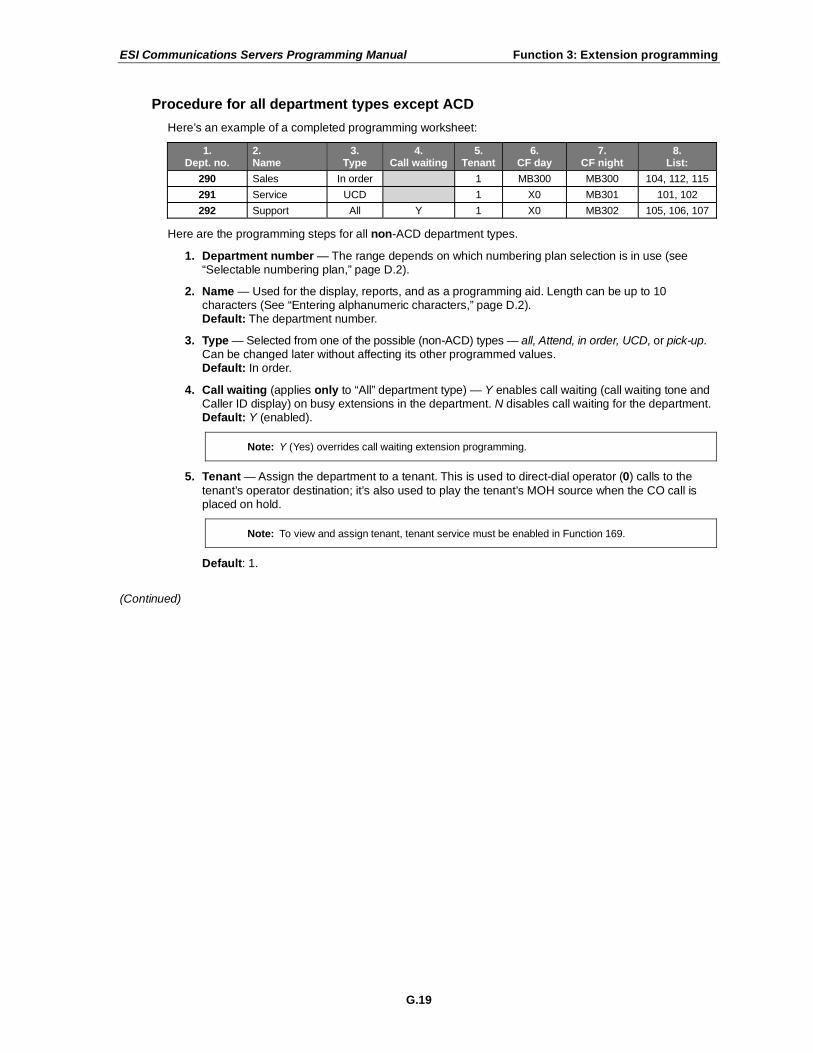
ESI Communications Servers Programming Manual Function 3: Extension programming
G.19
Procedure for all department types except ACD
Here’s an example of a completed programming worksheet:
1. Dept. no.
2. Name
3. Type
4. Call waiting
5. Tenant
6. CF day
7. CF night
8. List:
290 Sales In order 1 MB300 MB300 104, 112, 115
291 Service UCD 1 X0 MB301 101, 102
292 Support All Y 1 X0 MB302 105, 106, 107
Here are the programming steps for all non-ACD department types.
1. Department number — The range depends on which numbering plan selection is in use (see “Selectable numbering plan,” page D.2).
2. Name — Used for the display, reports, and as a programming aid. Length can be up to 10 characters (See “Entering alphanumeric characters,” page D.2). Default: The department number.
3. Type — Selected from one of the possible (non-ACD) types — all, Attend, in order, UCD, or pick-up. Can be changed later without affecting its other programmed values. Default: In order.
4. Call waiting (applies only to “All” department type) — Y enables call waiting (call waiting tone and Caller ID display) on busy extensions in the department. N disables call waiting for the department. Default: Y (enabled).
Note: Y (Yes) overrides call waiting extension programming.
5. Tenant — Assign the department to a tenant. This is used to direct-dial operator (0) calls to the
tenant’s operator destination; it’s also used to play the tenant’s MOH source when the CO call is placed on hold.
Note: To view and assign tenant, tenant service must be enabled in Function 169.
Default: 1.
(Continued)

ESI Communications Servers Programming Manual Function 3: Extension programming
G.20
6. and 7. Call forward busy/no answer — The department can be set to call forward busy/no answer to an extension, another department, a mailbox or a branch ID for day mode and differently for night mode. The department can have its own mailbox for pickup by members knowing the password or forwarded to any mailbox type including guest, cascade, etc. Calls routed to an extension via a department will follow the department’s call forwarding. While calls
transferred to the extension will follow the extension’s call forwarding as programmed in Function 31 (see page G.2). Please note that the order that the extension numbers are entered will dictate the order called when the department selected is “in order.”
Important: Don’t call-forward a department to itself. This can cause line lock-up problems.
Default: First extension in the system.
8. Department list — Enter the extension numbers that are assigned to this department. To delete an extension number from a list, press HOLD. As mentioned above, the order that the extension numbers are entered will dictate the order called when the department selected is “in order.”
Example: Here is a portion of a completed Programming Worksheet for Department programming. Department 290 was created to have calls directed to it to first ring 104, then, if busy/no answer,
111, and then 112. If all are busy or do not answer, the call will forward to the operator if in day mode — or, if in night mode, to guest mailbox 300 for retrieval in the morning. Department 291 rotates calls between
the two extensions listed; if both are busy/no answer, calls go to the service manager (X105) — or, if in night mode, to Guest Mailbox 301, which has been set to page the tech on-call.
1.
Ext.
2.
Name
3.
Type
4.
Call wtg.
5.
Tenant
6.
CF day
7.
CF night
8.
List:
290 SALES IN ORDER 1 X0 MB300 104, 111, 112
291 SERVICE UCD 1 X105 MB301 101, 102

ESI Communications Servers Programming Manual Function 3: Extension programming
G.21
ACD
ACD department programming
ACD departments can be programmed to route calls based on several optional parameters. Each ACD station can be logged onto as many as two ACD departments at the same time. Also, each ACD station can be a member of up to 20 ACD departments (i.e., up to 20 log-on keys may be assigned to each ACD station.)
Each ACD agent must have a Digital Feature Phone1, IP Feature Phone II, Digital Cordless Handset, or
VIP Softphone. Agent log-on keys will be automatically assigned to the lower left programmable feature keys for the stations listed in ACD departments (with wrap keys automatically assigned above them; see “Feature keys,” page G.27).
Note: Line keys can’t be used to answer calls ringing Attend departments set in the live-ring list (in Functions 211, 2121, and 2131).
ACD overflow
Incoming calls that are holding (queued) for an available agent can be automatically forwarded to a new destination if ACD overflow is assigned. ACD overflow can be initiated by exceeding a maximum number of queued calls or by an individual exit timer set for each ACD department. If ACD overflow parameters aren’t assigned, the default action will be to overflow calls based on the system default ACD exit timer only. ACD overflow parameters are:
• Queue exit threshold — If the number of calls in queue matches a predetermined queue exit threshold, all subsequent calls to that ACD department will immediately follow that department’s call-forward destination.
• ACD exit timer — When a call has been held in queue for a predetermined duration specified for that ACD department, the call will follow the department call-forward destination. If the department’s ACD exit timer isn’t assigned, the system-wide default (for the current operation) will be used.
ACD agent priority
ACD agents who are simultaneously logged into two departments can have calls to one department take precedence over the other department’s calls. When the ACD station is assigned to each ACD department, the “baseline” priority is set for calls that are directed to that station from that department.
ACD call escalation (priority override)
An incoming call that has been in an ACD department queue the longest can be forced to ring at the next available agent, regardless of the priority setting of that agent’s station department log-in. A timer that’s set in ACD department programming (see page G.22) triggers this ACD escalation.
Note: Usually a caller will be forwarded to a department by the auto attendant. However, a user, too, can transfer a caller to the department number. The transferred call will be processed according to the above description, as if transferred by the auto attendant. If no agents are logged-on to an ACD
department, incoming calls will immediately follow the department’s call-forwarding setting.
1 Except 12-Key Digital Feature Phone.

ESI Communications Servers Programming Manual Function 3: Extension programming
G.22
Procedure (ACD)
Here’s an example of a completed programming worksheet for an ACD department:
1.
Dept. no.
2. Name
3.
Type
4.
Tenant
5.
CF day
6.
CF night
7. ACD
call esc. timer
8. Queue
exit threshold
9. ACD exit
timer
10. ACD
queue annct.
11. ACD
queue 2nd annct.
12.
List
13.
Agent priority
290 Sales ACD 1 MB300 MB300 0 0 0 538 539 104, 112, 115 1
291 Service ACD 1 X0 MB301 0 0 0 548 549 101, 102 1
292 Support ACD 1 X0 MB302 0 0 0 558 559 105, 106, 107 2
Here are the programming steps for ACD departments.
1. Department number — The range depends on which numbering plan selection is in use (see “Selectable numbering plan,” page D.2).
2. Name — Used for the display, reports, and as a programming aid. Length can be up to 10 characters (See “Entering alphanumeric characters,” page D.2). Default: The department number.
3. Type — Select ACD, for an ACD department. Default: In order.
4. Tenant — Assign the department to a tenant. This is used to direct-dial operator (0) calls to the tenant’s operator destination; it’s also used to play the tenant’s MOH source when the CO call is placed on hold.
Note: To view and assign a tenant, tenant service must be enabled in Function 169.
Default: 1.
5. and 6. Call forward busy/no answer — The department can be set to call forward busy/no answer to an extension, another department, a mailbox or a branch ID for day mode and differently for night mode. The department can have its own mailbox for pickup by members knowing the password or forwarded to any mailbox type including guest, cascade, etc. Calls routed to an extension via a department will follow the department’s call forwarding. While calls transferred to the extension will follow the extension’s call forwarding as programmed in Function 31 (see page G.2).
Important: Don’t call-forward a department to itself. This can cause line lock-up problems.
Default: X100.
7. ACD call escalation timer — If an ACD call is in queue longer than the setting of the ACD call escalation timer and has been in queue the longest, it will be sent to the next available agent, regardless of the ACD agent priority setting of that agent’s station. Setting this value to zero disables the timer. Range: 5–900 (seconds). Default: 0 (disabled).
8. Queue exit threshold — If the number of calls in queue to an ACD department matches the ACD queue exit threshold, a new call to that department will immediately follow the department’s call-forwarding destination. Setting this value to zero disables this setting. Range: 5–20 (calls in queue). Default: 0 (no threshold).
(Continued)
ESI Communications Servers Programming Manual Function 3: Extension programming
G.23
9. ACD exit timer — This is a department-specific timer for routing ACD calls that have been in queue too long. When a call has been held in queue for the duration specified by the ACD exit timer, the call will follow the department’s call-forwarding destination. Setting this value to zero causes the department to use the default ACD exit timer setting (Function 154
1).
Range: 5–900 (seconds). Default: 0 (use system setting in Function 154).
10. ACD announcement — This is the number of the recorded announcement played to a caller when all extensions in an ACD department are busy. Use the scroll keys or enter the announcement number.
2
11. ACD second announcement — This is played periodically to callers on hold in an ACD department when all extensions are busy. Use the scroll keys or enter the announcement number.
2
12. Department list — Enter the extension numbers that are assigned to this department. To delete an extension number from a list, press HOLD. Each station entered will automatically be assigned an agent log-on key, starting with the lower-left programmable feature key.
13. Agent priority — ACD extensions entered in the previous steps are selected using the scroll keys. The agent priority for each extension is entered using the keypad. Pressing # accepts the priority. (Pressing # without changing the priority will exit the function.) ACD agent priority can also be assigned at the ACD extension when programming an ACD log-on key (see Notes, below). Stations that are logged into more than one ACD department can have incoming ACD calls prioritized by department. ACD priority designates which department’s queued calls will be answered first when an ACD station is logged onto two departments. When both departments have
calls in queue, the calls queued to the department with the highest priority will be answered first, regardless of how long they’ve been in queue. If the departments’ ACD priority settings are equal, then the call held in queue the longest will be answered first. Use the scroll keys to select the station and use the keypad to enter the priority. To confirm, press #. Range: 1–4 (with 1 being highest priority). Default: 1.
Example: Extension 102 is a member of ACD departments 291 and 292. The log-on key for
department 291 is priority 1; the log-on key for department 292 is priority 2. Extension 102 logs onto both departments, and takes a call. A new call rings into department 292 and is queued. Several seconds later, a new call rings into department 291 and is queued.
Extension 102 releases the current call. The new call queued to department 291 rings on extension 102, even though the call queued to department 292 was in queue longer.
Notes: If a user has deleted an ACD log-on key, the station will be automatically logged out of the
ACD department; however, it will remain assigned to the department. If an ACD log-on key is being assigned at the station, the user may enter a new priority for
the department to which the log-on key is associated. Pressing # without entering a new priority will set the priority to what is assigned here.
A station can’t have a log-on key programmed for a department of which it is not a member.
Limitations
• ACD extensions can’t set call forwarding (5 6 5 or 5 6 7) if logged-onto an ACD department.
• The longest time available remains the criterion for delivery of the next ACD call to an agent station.
Example: Agent station 123 is logged into departments 290 and 291, and a call is presented to department 290.
Station 123 answers the call, assists the caller, and hangs up. A call is presented to department 291; the call will be sent to an agent station that was idle longer than station 123 was.
1 Function 154: ACD exit timer — The amount of time (in seconds) that a call will remain in ACD department queues before following the
department re-route. 2 For information about recording announcements, see “Function 61: Re-record system and branch prompts,” page J.1.

ESI Communications Servers Programming Manual Function 3: Extension programming
G.24
Function 332: VIP ACD parameters
This function establishes settings to be used for VIP ACD. It covers programming for the database owner,
the real-time display clearing, and the service level.
Note: See also the VIP ACD Supervisor Setup and User’s Guide (ESI # 0450-0986).
Function 3321: Assign database owner
Enter the extension that will be the VIP ACD database owner (the VIP ACD Supervisor extension that collects and stores ACD events in the ACD event database). Only one extension is needed, regardless of the number of ACD departments in the system.
Important: This extension must keep its VIP ACD Supervisor application running at all times, in order to collect
event records that will be stored in the ACD event database.
Function 3322: Manual real-time display clearing
Enter the number of the department whose real-time statistics are to be cleared.
Clearing the real-time statistics resets the counters in the VIP ACD Supervisor Department Details (real-time statistics) display to zero, so new statistics can be calculated until the display is manually or automatically cleared again.
Function 3323: Automatic real-time display clearing
At a programmed time, this function clears the real-time statistics, which automatically resets the counters in the VIP ACD Supervisor Department Details (real-time statistics) display to zero. Only one clearing time can be set per department.
1. Enter the department number.
2. Select ENABLED or DISABLED. Default: DISABLED.
3. Enter the time (in 24-hour format) when the department’s real-time statistics are to be cleared. Range: 00:00–23:59. Default: 00:00.
Function 3324: Service level
This function sets the threshold time, in minutes and seconds, by which service level is determined for the VIP ACD Supervisor Department Details display. The service level is calculated by dividing the number of calls answered within the threshold by the last 30 calls presented to the queue. (The number of calls used to make this calculation — 30 — is rolling and can’t be adjusted.)
Example: The threshold time is set to 02:00 (two minutes, zero seconds; that’s the default). Thus, each call
must be answered within two minutes from the time it goes to the department. If 30 calls are presented and the department agents answer 20 of them within each call’s two-minute threshold time, the service level is 67% (20 ÷ 30 = 0.6667). This percentage will appear in the supervisor’s
Department Details display.
Range: 00:00–16:00 (zero to 16 minutes). Default: 02:00.

ESI Communications Servers Programming Manual Function 3: Extension programming
G.25
Function 34: Flexible number assignment
This function lets the Installer reassign numbers outside of the numbering template. Extensions, guest mailboxes, and departments can have their numbers exchanged with each other, in any combination (e.g., you can exchange extension 1000 with guest mailbox 3000, or swap the number of department 1450 with that of guest mailbox 3000).
Important: Mailbox greetings, feature keys, and Personal Dex entries won’t be changed (i.e., the programming won’t move with a number’s extension/mailbox).
To complete this operation, the system must be idle.
1. Enter Installer programming, and then enter Function 34.
2. Enter the number you wish to reassign, and press #.
FLEX NUMB ASSIGN
1ST EXT: 1044
3. Enter the second number. (the first number now appears in the top line), and press #.
X1044 J SMITH
NUM: 3001
4. Both extensions now appear in the display. Confirm the reassignment by pressing #.
X1044 J SMITH
X3001 M JONES
Dial plan range reassignment
Note: This part of Function 34 is available only through ESI System Programmer.
After a dial plan has been selected in Function 169 (page E.10), the Installer can reassign one or more ranges of numbers of extensions and guest mailboxes by using Function 34 in ESI System Programmer. This function can be used either at system installation or thereafter. Before applying any changes, you must make sure the
system is completely idle. This function can be used to change the numbers of all extensions or guest mailboxes, or a subset of them. However, both ranges — the numbers to be changed and the new numbers — must be contiguous.
Example: The Installer selects three-digit dial plan 200, which includes extensions in the default range 200–367. The customer wants extensions 240–310 to have new numbers: 160–199 and 400–430. Since the
requested new numbers are two different ranges, the Installer must use this function twice . . .
1. Numbers to change: 240–279. • New numbers: 160–199.
2. Numbers to change: 280–310. • New numbers: 400–430.
Only the extension/mailbox number will be changed with this function. The following parameters also will be changed if the extensions or mailboxes being changed are assigned in these functions:
• Ring assignments and private line (Function 21)
• Extension call-forward busy/no answer (Function 31)
• Extension features (Function 32)
• Department features (Function 33)
• Programmable feature keys on other station (Function 35 and user programming function 2)
• Auto attendant GoTo extension/mailbox branches (Function 41)
• Guest mailbox features (Function 53)
• Group mailbox members (Function 54)
• Recorded directory names (Function 62)
• Esi-Link published list (Function 834)
Warning: This function can take up to 30 minutes to complete, depending on the number of stations reassigned.

ESI Communications Servers Programming Manual Function 3: Extension programming
G.26
Function 35: Extension button mapping
By default, the programmable feature keys’ initial state is “not programmed” (except in the case of the first system extension, on which the upper-left key is a day/night key
1). Use this function to change the
programmable feature keys system-wide. Users can later change the programmable feature key positions for their stations as part of station programming.
Important: Future, system-wide changes made later here by the Installer will overwrite any station user programming.
When prompted, press the desired programmable feature key location, then enter the appropriate digits on the dialpad and confirm by again pressing the same programmable feature key.
To determine how a programmable feature key is currently programmed: press and hold the key; note how it is programmed; and press the key again.
The keys can be programmed as follows:
CO line key
With three-digit dial plans: If the dialed digits are 1–99, the key will serve as a CO line key. With four-digit dial plans: If the dialed digits are 1–240, the key will serve as a CO line key.
Note: Removing the line key appearances will set the station(s) to operate as a PBX with line access by dialing
9 (or 8 or 71–76).
Station key
If the digits entered constitute an extension number (or department, guest mailbox, etc.), the key will become a station key providing the appropriate lamp information (see also “Selectable numbering plan,” page D.2).
Department numbers programmed here will appear on all phones; however, agent log-on keys will appear only at the phones of assigned agents in the corresponding ACD department.
Guest/info mailboxes and group mailboxes can be assigned here to appear on all phones.2 However,
messages being left in these will not cause lamp appearances. (For more on the different kinds of mailboxes, see “Voice mail programming,” beginning on page I.1.)
Speed-dial key
If one enters 9 (or 8 or 71–76) plus a phone number, the key will become a speed-dial key for outside calls. Alternatively, the user may enter the system speed-dial bin.
Location Key
To facilitate dialing into a remote Esi-Link location, you may assign (700–799) a programmable feature key as a Location Key. When you press a Location Key, you’ll hear dial tone; you can then dial any extension, department, mailbox, or outside line group access code
3 in the remote location.
Feature Phone overlays
Each Feature Phone comes with one overlay for the programmable feature keys. To order additional overlays, visit the DESI
™ Web site, www.desi.com. While there, you may also want to download the free
Windows-based software, DESI Lite, which allows you to print on the overlays. For assistance with DESI products, contact DESI (the DESI Web site contains contact information).
Tip: Remember that ESI System Programmer software, available from www.esiresellers.com, also lets you
print on the overlays as well as perform many other programming tasks.
1 Stations programmed as ACD agents will have an log-on key automatically assigned to the bottom-left programmable feature key (see the
“Department list” step on page G.23). 2 However, it isn’t possible to assign either Q & A mailboxes or cascade notification mailboxes to station keys.
3 Depending on the assignment of Function 164.

ESI Communications Servers Programming Manual Function 3: Extension programming
G.27
Feature keys
Feature keys, as listed here, cannot be programmed system-wide but must be programmed for each
individual station. Refer to “Feature key chart” (page G.29) for specific availability by ESI phone model.
• Manual day/night mode (Code 560) — Allows manual setting of the system’s mode — day, night, day2, night2, holiday or auto (in auto mode, the system follows the day/night mode tables you have programmed).
1
Note: You or the Administrator can also change the mode and/or re-record the holiday greeting remotely to
handle unexpected closings, such as for inclement weather.
• Service observing (Code 561) — Allows authorized users to monitor others’ calls silently (e.g., in order to aid in quality assurance of call activity).
Note: You or the Administrator must authorize service observing for a station, and you must program the list of allowed extensions in Function 32 (page G.15).
• ACD agent log-on/off key (Code 5DDD) — Logs an agent on or off the ACD. The DDD represents the department number (for example, a key programmed with the code 5 2 9 0 would log an agent on/off Department 290). Automatically assigned to the lower-left programmable feature key when the station is listed as an ACD department member (see the “Department list” step on page G.23), it can be moved to any other available programmable key.
• ACD agent wrap key (Code 562) — Toggles “wrap mode”; i.e., keeps a logged-in ACD agent from receiving the next assigned call. For use in performing “wrap-up” activities, such as completing paperwork, following the agent’s most recent call.
• ACD administrator key (Code 563) — Allows a user to view the call activity of an ACD group. Set a
programmable feature key with 5 6 3 and the ACD department number (for example, 5 6 3 2 9 0), and then press the key. It will glow green and the bottom line of an ACD group's display will appear until you press the key again. The number of ACD administrator keys that can be programmed per department varies by ESI Communications Server model:
Model ACD administrator keys per department
ESI-1000 8
ESI-600 8
ESI-200 4
ESI-100 2
•
• Headset key (Code 564) — Provides for easy connecting to/disconnecting from calls when the user is operating in headset mode. The user presses the key to receive dial tone or to answer a ringing call; he/she then presses the key again (or RELEASE) to disconnect from the call.
• Call forward key (Code 565 or 565XXX) — Toggles call forwarding on and off. If the user always forwards to the same extension, you (or the user) can program a key with both 5 6 5 and the extension number.
• Redial key2 (Code 566) — Redials the most recently dialed number, as would pressing the REDIAL
fixed-feature key.
• Call forward/no-answer key (Code 567) — Sets or cancels call forwarding/no-answer. This overrides the call forward busy/no-answer assignment in Function 31.
• Message monitor key (Code 568) — Toggles message monitor mode. (Functionally is same as pressing PROGRAM 3 6 and following the prompts.)
• Background announce key (Code 569) — During call waiting, pressing (and holding down) this key lets the user make a brief, private background announcement to the station's earpiece (if the user has enabled the background announce feature).
• Conference (Code 570)2 — Serves the same function as the CONF fixed-feature key.
1 If tenant service (Function 169) is enabled, using this key will set the mode of only the tenant to which the station is assigned.
2 Programmable on only the 12-Key Feature Phone.

ESI Communications Servers Programming Manual Function 3: Extension programming
G.28
• Personal greeting keys (Codes 571–573) — These provide for easy activation of one or more of the user’s personal greetings. Each key's LED will be green for the associated personal greeting that is active. These keys can be used in place of, or in conjunction with, manual activation of the greetings in programming mode.
• Caller ID (Code 574) — Allows the user to view the 25 calls presented most recently to his station. Caller ID records are stored only for those phones which have a Caller ID key assigned.
• Virtual Answer Keys (Codes 575 and 576)1 — Pressing a Virtual Answer Key when the extension
receives a call-waiting alert causes the system to play a greeting to a caller and then route the caller to a desired destination. (For more details on this feature, see the User’s Guide.)
• QuickPage (Code 577) — Normally used by an operator, this key lets the user quickly put on hold, and page, a station user. While on a CO line call, the user can press a QuickPage key and then enter a station number (or press a programmable feature key programmed for an extension), and the system will automatically page the person
2, then forward the call to the person’s voice mailbox if he/she doesn’t answer.
• Mute/DND (Code 578)3 — Serves the same function as the MUTE/DND fixed-feature key.
• Voice mail (Code 579)3 — Serves the same function on a 12-Key Feature Phone as pressing
VOICE MAIL on a 24-Key or 48-Key Feature Phone.
• Override ring key (Code 580) — Allows a user to place an outside call (CO, extension, Esi-Link or Remote Phone) while another call is ringing in on the same station.
• Door control (Code 581) — For ESI Presence Management only. For more information, see the ESI Presence Management Installation Manual (ESI # 0450-0792).
• Record (Code 582) — For ESI Cordless Handsets only. Pressing this key performs the same as does the fixed RECORD key on ESI desktop Feature Phones.
• Quick Switch (Code 583) — When programmed, pressing this key lets the user transfer active calls between a desktop ESI Feature Phone and either an ESI Cordless Handset or VIP Softphone. It also allows the user to set specific ring options when simultaneously using a desktop ESI Feature Phone and either an ESI Cordless Handset or VIP Softphone.
• Account codes (Code 584) — When programmed, pressing this key lets the user send account codes during a call.
• LCL (Code 585) — Used only on Remote IP Cordless Handset. When programmed, this key accesses a local analog CO line.
• Overhead page (Code 599) — Allows the user to access the overhead paging system.
Note: To delete a programmable feature key, press HOLD instead of programming a value.
1 Not available on an ESI Cordless Handset.
2 The system will access the paging zone for the extension and play the user’s name as recorded in the directory (if no name is recorded, it will page
by extension number) followed by the phrase “you have a call on hold” and the line on which the caller is held — e.g., “John Doe, you have a call on line 21.”
3 Programmable on only the 12-Key Feature Phone.

ESI Communications Servers Programming Manual Function 3: Extension programming
G.29
Feature key chart
Note: These codes are not applicable to SIP phones.
Code1 Feature key
12-Key Phone
ESI Cordless Handset
24/48-Key Phones
560 Manual day/night mode key Y Y
561 Service observing key Y Y
5DDD ACD agent log on/off key Y Y
562 ACD agent wrap key Y Y
563DDD ACD Administrator key Y Y
564 Headset key Y
565 Call forward key Y Y Y
565XXX Forward to a destination Y Y Y
566 Redial Y
567 Call forward/no-answer key Y
568 Message monitor key Y Y
569 Background announce key Y Y
570* Conference Y
571 Personal Greeting 1 Y Y Y
572 Personal Greeting 2 Y Y Y
573 Personal Greeting 3 Y Y Y
574 Caller ID key Y
575 and 576 Virtual answer keys Y
577 QuickPage Y Y
578 Mute/DND Y (DND only)
579 Voice mail Y
580 Override ring key Y Y
581 Door control Y Y
582 Record Y
583 Quick Switch Y
584 Account codes Y Y Y
585 LCL (local analog CO line) key Y2
599 Overhead page Y Y Y
Virtual Mailbox Key
If the entered digits are an extension number for a guest, department mailbox, cascade mailbox, etc., the key will provide for direct transfer to that mailbox, as described above. However if you program VOICE MAIL and an extension or mailbox number, it will become a Virtual Mailbox Key, which will indicate message status for the mailbox (the LED will blink red if new messages exist) and provide direct pick-up of the messages.
To create a Virtual Mailbox Key of a user extension’s mailbox, press VOICE MAIL and then enter the
applicable extension or mailbox number.
Private line key
If a private line has been established in CO line programming (see “Private line,” page F.6), that CO line key
must appear on that station’s phone to allow outbound access to the line.
1 DDD = ACD department number. XXX = Forwarded-to extension.
2 Only on Remote IP Cordless Handset.

ESI Communications Servers Programming Manual Function 3: Extension programming
G.30
Function 37: RFID programming
Choices are:
• 1 — Access control schedule programming.
• 2 — RFID tag assignment.
• 3 — View RFID tag number.
• 4 — ESI Presence Management parameters.
Note: For more information about ESI Presence Management, consult its Installation Manual (ESI # 0450-0792).
Function 371: Access schedule programming
Access schedules are used to allow or deny door access with electronic keys (“RFID tags” on the system display) at certain times of the day. Up to seven access schedules can be programmed. Each schedule has an allow access time and a deny access time for each day of the week. By default, all access schedules allow access 24 hours a day, seven days a week.
Note: Access schedules don’t take effect until the current time has passed the next schedule time. For example:
if you program a schedule time to deny access Wednesdays at 5:30 PM but it’s already 5:45 PM on Wednesday when this programming occurs, the change won’t take effect until the following Wednesday.
1. Using the scroll keys, select the access schedule to be programmed. Press # to confirm. Range: 1–7.
Note: Schedule 0 (default of full-time access) isn’t selectable.
ACCESS SCHEDULES
1-ACC SCHED1 >
2. Enter the name of the schedule (up to 10 characters in length). Press # to confirm. Default: ACC SCHED[x], where [x] represents the access schedule selected in step 1.
ACC SCHED1
NAME:
3. Use the scroll keys to select the day of the week to program for the selected access schedule. Press # to confirm.
ACC SCHED1
DAY: MONDAY >
If you haven’t yet assigned an allow time (see next step) for this schedule, the display will show something like:
ACC SCHED1 MON
NO ALLOW TIME
(Continued)

ESI Communications Servers Programming Manual Function 3: Extension programming
G.31
4. Enter the allow time — the time when an electronic key user can begin controlling door locks — in 12-hour format. (To delete an entry, press HOLD.) Press # to confirm when done.
ACC SCHED1 MON
ALLOW: 900
5. Select AM or PM by pressing a scroll key. Press # to confirm.
ACC SCHED1 MON
ALLOW: 900 AM
If you haven’t yet assigned a deny time (next step) for this schedule, the display will show something like:
ACC SCHED1 MON
NO DENY TIME
6. Now, enter the deny time — the time when an electronic key user begins to be denied door lock control — in 12-hour format. (To delete an entry, press HOLD.) Press # to confirm when done.
ACC SCHED1 MON
DENY: 700 >
7. Select AM or PM by pressing a scroll key. Press # to confirm.
ACC SCHED1 MON
DENY: 700 PM
8. Press # again to exit the function, or select another day of the week by using the scroll keys and then go back to step 4.

ESI Communications Servers Programming Manual Function 3: Extension programming
G.32
Function 372: RFID tag number programming
As described earlier in this document, each electronic key has an embedded unique RFID tag number. This
function is used to associate each RFID tag number to an extension or mailbox for Personal Call Routing and presence indication (except mailboxes). If Personal Call Routing or presence indication is not desired but access control is required, enter 0 instead of an extension or mailbox number.
1. Enter an RFID tag number, or use the scroll keys to select from the list of tag numbers.
Note: If using any RFID features — i.e., if using ESI Presence Management for anything more than its
doorphone capabilities — you should save time by first scanning the electronic keys at any RFID Reader connected to the system. The system will store the electronic keys’ tag numbers automatically, and you can use the scroll keys to select the tag numbers to be assigned.
To delete a tag number, press HOLD. Press # to confirm.
TAG ID: 2
9012345678 >
The tag ID is the list index of the RFID tag number.
Note: If a tag number is entered manually but the tag limit has been exceeded, LICENSE EXCEEDED will appear on the display. Therefore, you must delete one or more unassigned tag numbers. To view the system’s total number of RFID licenses, use Function 81 (see page M.1).
2. Enter the extension or mailbox number to which you wish to assign the tag number. If no extension or mailbox is to be assigned this tag number, press 0. (To delete an entry, press HOLD.) Press # to confirm.
RFID TAG PROG
EXT OR MB:
3. Enter the extension numbers of up to the system limit1 of ESI Presence Management RFID Readers for
which this tag is allowed to control door access. To give the tag access to all doors, press FLASH. (To delete an entry, press HOLD.) Press # after each entry and then press # again to confirm (in other words: after the last entry, you’ll press # twice).
Note: If all ESI Presence Management RFID Readers are allowed, “ALL” will appear on the second line.
DOOR ACCESS:
123 124 138 >
4. Use the scroll keys to select an access schedule. Access schedules are used to allow or deny door access with an electronic key at certain times of the day. Each day of the week can have a start time to allow access and a stop time to deny access. To allow constant (“full”) door access, select 0 - FULL. Otherwise, select a schedule to restrict access. The schedule name will appear. Range: 1–7. Default: 0 (full)
Note: You assign access schedules in Function 371 (see page G.30). If not using access schedules, select 0 – FULL.
ACCESS SCHEDULE:
0 - FULL >
1 For details on the maximum number of RFID Readers that can be entered for your system, see “ESI Presence Management features” in “System
capacities” (page B.1).

ESI Communications Servers Programming Manual Function 3: Extension programming
G.33
Function 373: View RFID tag number
This is used to display tag numbers that are associated to extensions or mailboxes. You can only view tag
numbers with this function. You cannot change any tag numbers or assignments.
Enter the station or mailbox number to display, and then press #. If there’s an RFID tag number assigned to that extension or mailbox, it will appear.
RFID TAG DISPLAY
EXT:
Tip: You can use ESI System Programmer to print out a list of assigned tag numbers.
Function 374: ESI Presence Management parameters
Playing prompts
This determines whether the system plays a prompt — and, if so, which one — when the ESI Presence
Management RFID Reader reads an electronic key. Select YES to enable playing of the prompt or NO to disable playing of the prompt. Default: YES (a prompt will play).
EPM RFID READER
PROMPTS: YES >
When this function is set to NO, no prompts will play through the ESI Presence Management RFID Reader. When “EPM RFID Reader prompts” is set to YES, prompts will play as shown below. (These prompts can’t be customized.)
When the RFID Reader displays: It plays this prompt:
WELCOME “Welcome”
GOODBYE “Goodbye”
ACCESS DENIED “Invalid entry”
LICENSE EXCEEDED “Error”
ERROR
READER FULL
“Error”
Enable/disable sending time and attendance records
Notes: The NSP must be programmed and connected to a local area network for time and attendance record collection.
Only ESI Presence Management RFID Readers programmed as type ENTRANCE/EXIT (Function 31) generate time and attendance records.
This parameter is used when the optional ESI TimeLine time and attendance management software application is used in conjunction with the ESI Presence Management RFID Reader. Use the scroll keys to enable or disable time and attendance records, and press # to confirm. Default: Disabled.

ESI Communications Servers Programming Manual Function 3: Extension programming
G.34
Function 375: RFID Reader parameters
This function is used to adjust the doorphone speaker volume of each ESI Presence Management
RFID Reader.
1. Enter the extension number of the RFID Reader.
EPM READER SET
EXT:
2. Select the volume level by using the scroll keys.
X211 FRONT DOOR
VOLUME: 6 >
Range: 1–8, with 8 as the highest. Default: 4.

ESI Communications Servers Programming Manual Function 4: Auto attendant programming
H.1
Function 4: Auto attendant programming
You can program the auto attendant, in line programming (Function 2; see page F.1), to answer calls immediately, on a delayed-answer basis or not at all (i.e., for live answer at all times). If required, you also can program different main greetings and routing schemes for different combinations of lines. Day/night mode will
change the main greeting announcement and affect rerouting of calls during call processing.
Function 41: Auto attendant branch programming
An ESI Communications Server’s auto attendant follows a branch concept: the caller is routed through a series of branches, ultimately to the extension he wishes to reach. The caller moves from branch to branch by selecting a number or name presented in a branch prompt.
Each system supports four types of branches — menu, GoTo, directory, and remote — and up to 100 branches, total. Use them to create virtually limitless routing possibilities. Each branch has one greeting — with the exception of branches ID 1 through ID 8, each of which has four greetings (day1, day2, night1, and night2; see
also “Function 43: Automatic day/night mode table,” pp. H.7–H.8).
Note: If tenant service is enabled in Function 169 (see page E.10), branch ID 1 will associated with tenant 1, and so on through branch ID 8 and tenant 8. Day/night routing for each tenant will be controlled
either automatically by the day/night table for each tenant or manually with a day/night key on a station assigned to that tenant. Dialing 0 from a call to each of these ID branches will route the call to that tenant’s respective “dial-0” destination.
Branch ID
Tenant
ESI-1000 ESI-600 ESI-200 ESI-100
1 ID 1 ID 1 ID 1 ID 1
2 ID 2 ID 2 ID 2 ID 2
3 ID 3 ID 3 ID 3
4 ID 4 ID 4 ID 4
5 ID 5 ID 5
6 ID 6 ID 6
7 ID 7 ID 7
8 ID 8 ID 8
Menu branch
A menu branch includes a prompt that instructs the caller to make a selection from the choices presented such as “For Sales, press 1; for Service, press 2; or, for Administration, press 3.” Whenever you create a
menu branch, you must also create a corresponding number of sub-branches to match the number of choices given the caller in the prompt.
When a caller makes a single-digit selection in the menu branch, he/she will then advance to one of its sub-branches — which could be another menu branch (if there are more choices to make), or a GoTo branch (routes the caller to a destination; see below) or directory branch (for choosing from a list of names; see page H.3).
Notes: IDs 1–8 are always menu branches and can’t be changed.
If a caller makes no selection during the prompt in a menu branch, he will be transferred according to the no-response programming for that branch (see page H.6).

ESI Communications Servers Programming Manual Function 4: Auto attendant programming
H.2
GoTo branch
A GoTo branch transfers the caller to an extension, department, mailbox, branch ID, or an outside number:
• GoTo dial — The GoTo: dial branch automatically blind-transfers the caller to the extension or department number programmed as its destination. If the number listed is a department, the system will follow the programming as set in Function 33 (see page G.18). If the destination extension or department dialed is busy or does not answer, the call will follow call forwarding for the extension as programmed in Function 31 (see page G.2) or the department as programmed in Function 33 (see page G.18).
• GoTo mailbox — Routes a caller to that mailbox’s personal greeting. The mailbox can be a user, a guest/information mailbox, a group mailbox, cascade notification mailbox, or Q & A mailbox.
• GoTo branch — Can also be used to jump to any other branch in the auto attendant. It is a good idea to provide a jump as a sub-branch of each menu branch, giving the caller the option either to repeat the menu or exit without making a selection.
Example: “For widget sales, press 1. For gadget sales, press 2. Or, to return to the main menu, press 3.” In this case, the third sub-branch would be a GoTo branch with ID1 (the main greeting) as its
programmed destination.
• GoTo outdial — The GoTo branch can be used to transfer to an off-premises location, either in conjunction with Centrex lines or trunk-to-trunk. When you select GoTo, the system will prompt you for one of those two options. The branch’s dial string can be programmed to include pauses, flash hooks, etc. Use the scroll key to
enter special characters; use the scroll key to backspace. Press # to confirm the inserted character and continue. Press # # to complete the entry. The codes are:
Code Produces . . .
# # DTMF tone DTMF tone
F Flash hook
P Two-second delay
E The most recently attempted extension number
Example: To create an outdial string for Centrex that...
• Sends a flash hook • Dials a two-second delay
• Dials 9 (Centrex access code) • Dials another two-second delay • Dials 555-903-5642 (a local 10-digit call, in this example)
• Goes on-hook
... enter the following dial string:
[the system will display F 9 5 5 5 9 0 3 5 6 4 2 ]
If you selected Centrex: The system will dial the string as programmed and then release the call to Centrex to complete the connection.
1
If you selected trunk-to-trunk: The system will access another CO line to call the outdial number.
Note: Two CO lines will be utilized, one for the inbound call and one to call the outdial number.
(Continued)
1 Be sure the flash hook duration (Function 151, page E.3) is set for the correct timing recognized by the local telco provider.

ESI Communications Servers Programming Manual Function 4: Auto attendant programming
H.3
1. Enter the outdial number (including the access code and any special characters1). The system will prompt
you to indicate whether DTMF detection at the remote end is required before completing the connection. If DTMF detection is not required, the system will complete the trunk-to-trunk connection after dialing the final digit of the outdial number (blind transfer), so you may ignore step 2. However, if DTMF detection is required, proceed to step 2.
Example: To create an outdial string for trunk-to-trunk transfer that...
• Dials 9 (line group number) • Pauses for dial tone
• Dials 555 903-5642 (a local 10-digit call, in this example) • Goes on-hook
... enter the following dial string:
[Exception: Don’t enter the P if using PRI, which doesn’t require this after the trunk group access code.]
2. For the outdial number, set the day call-forwarding and then the night call forwarding.
After the final digit of the outdial number, the system will begin to play to the called person the following: “You are receiving a forwarded call. Press any key to accept.” This will play continuously for 30 seconds.
What happens now depends upon whether the system detects DTMF from the called party:
• If it does, the system completes the trunk-to-trunk connection.
• If it doesn’t, the system forwards the call to the programmed call forwarding for this outdial branch (the next step for which you’re prompted if DTMF detection is required).
Notes: You’ll be prompted to enter a call forwarding destination for an outdial branch only if (a.) the branch uses
trunk-to-trunk and (b.) DTMF detection is required. Enter an extension, branch ID or mailbox number for the day/night call forwarding of this GoTo Outdial branch.
While both COs are connected, the system constantly monitors the lines for open loops. If it detects an open loop on either line, it terminates both CO connections. Additionally, the system periodically will monitor for voice on the connected COs. If it detects no voice traffic, it terminates both CO connections.
Finally, if both COs are connected for 60 minutes, the system will terminate the connection, regardless of the presence or absence of activity.
Directory branch
A directory branch lets the caller connect by selecting a name from one of two types of directories:
• All-names — The caller selects the person he wishes to reach from the playback of all recorded names (use this if there are about 10 or fewer names in the directory). The system plays the names in alphabetical order according to the extension names programmed in Function 31 (see page G.2).
• Alpha — The auto attendant prompts the caller to enter up to three letters of the individual's first or last name
2 and then plays the matched names in alphabetical order according to the extension names
programmed in Function 31 (see page G.2). A second prompt then instructs the caller to press # when he/she hears the name of the individual.
Note: The actual recording of the names and alpha “key” entry (if the directory type is alpha) will come later in Function 62 (see page J.2). The directory branch(es) will not be enabled until at least one name has been recorded. To re-record the directory prompt, “Enter the first three letters of the person’s first
name that you wish to reach,” you must enter Function 61 and then record the prompt for the ID number of the directory branch.
1 Special characters — such as P for pause or F for flash — can also be entered in the dial string.
2 See “Field 5: Name key digits” under Function 165, page E.6

ESI Communications Servers Programming Manual Function 4: Auto attendant programming
H.4
Remote branch (Esi-Linked systems only)
The remote branch type1 can route calls to remote location destinations. For example:
• Location + branch ID — Routes caller to a menu branch at a remote location.
Note: Only branch IDs 8700 through 8798 at the remote location are supported.
• Location + department — Routes caller directly to a department at a remote location.
• Location + extension — Routes caller directly to an extension at a remote site.
• Location + mailbox — Routes caller directly to a voice or information mailbox at a remote site.
When you assign a remote branch to send a call to a branch ID at a remote Esi-Link location, that branch ID
(i.e., the destination branch ID) must be within the range of ID 8700 through ID 8798. This is to insure the correct setup of an Esi-Link auto attendant for incoming calls from remote locations.
Each remote branch can have a forward/no-response (NR) destination programmed to which the branch will send a caller if any of the following should occur:
• All Esi-Link channels are busy;
• The Esi-Link connection to the remote location is either off-line or unavailable;
• The caller is returned to the original location via branch ID 8799.
The forward/no-response destination can be one of the following destinations:
• Local branch ID
• Local station or department number
• Local voice mailbox (user, guest, or information)
In the event all Esi-Link channels are busy or unavailable, the caller will be directed to the forward/no-
response destination after hearing the prompt, “Destination unreachable.” If a forward/no-response destination isn’t assigned, the caller will be sent to the Operator at the originating location. Typically, the forward/no-response destination would be a GoTo branch to the menu branch to which the caller was last connected, such as branch ID 1.
At the remote location, when branch IDs 8700 through 8798 are assigned as GoTo branches, the branch destination will be limited to the return branch (ID 8799; see “Return branch,” below) and internal destinations at that location (i.e., local ID branches, departments, extensions, mailboxes, and COs only).
Return branch
Branch ID 8799 is a special, pre-programmed branch that’s used to send a caller back over the Esi-Link network to the no-response forward of the originating location ID branch that routed the call. To use this
branch, assign (at the remote location) a GoTo branch to ID 8799. When the caller is sent to this GoTo branch, he/she automatically will be sent back to the no-response destination of the originating location branch ID.
1 For more information about Esi-Link, see “Function 83: Esi-Link programming,” pages M.8–M.9.

ESI Communications Servers Programming Manual Function 4: Auto attendant programming
H.5
Auto attendant programming example
(The branch IDs and branch titles shown are for programming purposes only. The caller needs only to press 1, 2, etc., to move through the choices.)

ESI Communications Servers Programming Manual Function 4: Auto attendant programming
H.6
Programming sequence
1. Branch ID — A numerical designator which indicates its location and relationship to the other
branches. There can be up to six levels of branches — the first level being a single digit, the second level being two digits, and so on. The Main Greeting is ID 1 (or, additionally, 2 through 8 if a different greeting for each different line is desired); each of its sub-branches will have that number, plus an additional digit of its own (corresponding to choices given to the caller, shown here in bold): 11, 12, 13, etc. Menu Branch 123 would have sub-branches 1231, 1232, etc.
2. Type — Use a scroll key to select a menu, GoTo, directory, or (if Esi-Link is in use) remote branch. Press # to continue.
3. Name — Enter the name to help identify the branch for later programming changes; this also is the
source for reports and display information at users’ phones. Press # to continue.
4. Destination — Each branch type has different possible destinations as indicated:
Branch type Destination(s)
Menu Sub-branches (created later)
GoTo Extension, mailbox, branch ID, or outside number
Directory List of names (entered in Function 62)
Remote (Esi-Link only) Extension, mailbox, branch ID, or department
Use a scroll key to select the desired branch type and press #. Then, enter the destination — either an extension or department (EXT), mailbox (MB), or branch ID (ID) — and its number. Press #.
Additional programming notes
• Automatic disconnect — If ID 9999 is programmed as a destination, the call will be automatically disconnected.
• Call-forward busy/no answer — Can be programmed (and will be prompted for) only if a trunk-to-trunk outdial number is the destination of a GoTo branch.
• Call-forward no-response — Programmed (and will be prompted for) only for a menu, directory, or remote branch.
Deleting a branch
To delete a previously created branch, enter the branch ID, press HOLD, and confirm by pressing a scroll key
(either or ) and then #.
Function 42: Announce extension number
If a caller selects a name from a Directory Branch, the system can be set to announce the extension number prior to transferring the call. This provides the caller with the extension number for future direct dialing from a Menu Branch such as the Main Greeting. This feature should not be used where individual privacy is desired. Default: Enabled.

ESI Communications Servers Programming Manual Function 4: Auto attendant programming
H.7
Function 43: Automatic day/night mode table
You program the day/night mode table by selecting the day of the week, then entering the start time, and then selecting the mode — day, night, day2 or night2.
1 At the time you’ve programmed, the appropriate greeting for
that mode will play and the system will follow the appropriate day or night forwarding. Day forwarding is the same for both day mode and day2 mode; night forwarding is the same for both night mode and night2 mode. Enter the
times in military time (0000–2359). Each day can have up to six different times.
1. Enter the tenant number.
2. Select the day of the week by pressing a scroll key (either or ).
3. Press # to confirm.
4. Enter the day’s start time in 24-hour format.
5. Press # to confirm.
6. Select the mode — DAY, NIGHT, DAY2 or NIGHT2 — by pressing a scroll key (either or ).
7. Press # to confirm.
8. Repeat steps 4–7 for the day’s next setting or press # again to program another day.
9. When finished, press # again to exit.
Note: To delete an entry, press HOLD.
Day/night mode worksheet example
In the example below, the company or tenant has:
• Day mode programmed for: 8 AM to 12 noon Monday, Tuesday, Thursday, and Friday; 8 AM to 2 PM Wednesday and Saturday; and 1 PM to 5 PM Monday, Tuesday, Thursday, and Friday.
• Night mode programmed for after 5 PM Monday, Tuesday, Thursday, and Friday.
• Night2 mode for Wednesday and Saturday after 2 PM and all day Sunday.
• Day2 mode for lunchtime Monday, Tuesday, Thursday and Friday.
Tenant 1
MON TUE WED THU FRI SAT SUN
Start time
Mode
Start time
Mode
Start time
Mode
Start time
Mode
Start time
Mode
Start time
Mode
Start time
Mode
1 0800 D 0800 D 0800 D 0800 D 0800 D 0800 D
2 1200 D2 1200 D2 1400 N2 1200 D2 1200 D2 1400 N2
3 1300 D 1300 D 1300 D 1300 D
4 1700 N 1700 N 1700 N 1700 N
5
6
Note: For the schedule to take effect, the system must be placed in the “auto” mode.
1 Available only on branches ID1–ID8.

ESI Communications Servers Programming Manual Function 4: Auto attendant programming
H.8
Remote setting of day, night, holiday and auto modes
Normally, the system’s day/night mode operation will be manually controlled at an ESI Feature Phone and/or
set to follow the day/night mode tables (programmed by the Installer) automatically. In addition, the Administrator can remotely change the mode and/or re-record the holiday greeting to handle unexpected closings such as for inclement weather.
Remotely logging into the system with either the Installer password or the Administrator password lets the caller do the following for branch IDs 1–8:
• Re-record the greetings (day, night, day2 and night2).
• Re-record the holiday greeting.
• Change the mode to day/night/holiday/day2/night2 (or auto).
1. At the main greeting, enter 7 8 9 # or 4 5 6 # — or the new password — to enter remote programming mode.
2. You’ll hear prompts that will allow you to change the answer mode (day, night, day2, night2, holiday or auto) and/or to re-record the holiday greeting and the main greeting (ID 1). Follow the prompts to perform the desired operation.
Note: To access these options for branch IDs 1–8, you must call in on the phone number of the tenant
that uses those branches.
3. Exit by pressing and hanging up.
Prompts for remote settings: an outline
1 Set answer mode
1 Day mode 2 Night mode 3 Holiday mode 4 Use day/night table* 5 Day2 mode 6 Night2 mode
2 Record holiday main greeting
3 Record daytime main greeting
4 Record nighttime main greeting
5 Record day2 main greeting
6 Record night2 main greeting
Note: If the system is answered live and call is then routed to a mailbox, the Administrator can press 8 to return
to the main greeting and then follow the steps for making remote settings.
* This is used if the Installer has programmed an automatic calendar.

ESI Communications Servers Programming Manual Function 5: Voice mail programming
I.1
Function 5: Voice mail programming
To simplify initial installation, all programmed extensions will automatically have the generic personal greeting, “You have reached the mailbox for extension [xxx].” The mailbox user should replace this with a personalized greeting. Each guest/info, group, cascade notification, or Q & A mailbox must have a greeting recorded for the
system to consider the mailbox active.
Important: A mailbox will not receive broadcast messages until a greeting has been recorded for it. Additionally: If the greeting is deleted, the mailbox will be considered inactive. On the 12-Key Feature Phone, it is necessary to assign the code 5 7 9 (voice mail) to a programmable
feature key for the mailbox to become active.
If a programmable feature key is programmed as a Virtual Mailbox Key with any mailbox number, the key’s LED will blink, to indicate that new messages exist.
1 To retrieve messages from a station, either (a.) press the Virtual
Mailbox Key or (b.) press VOICE MAIL and then enter the mailbox number. To record a greeting, press
PROGRAM and enter the mailbox number; then press # to confirm, and follow the prompts. The default password is the mailbox number. To retrieve messages from the outside, press and enter the mailbox number during the main greeting. To enter mailbox programming from any ESI phone on the system, press PROGRAM and enter the mailbox number.
Function 51: Maximum message/recording length
Although the system will store only the actual message as left by the caller, the time set here is the maximum time to allow for a message. The range is 1–60 minutes for messages, and 1–120 minutes for recordings and greetings. (The maximum number of new messages and recordings in a mailbox, regardless of length, is 128.)
Default: 3 (minutes) for messages, 10 (minutes) for recordings.
Function 52: Message purge control
To avoid having unneeded messages filling up the system’s memory, values entered here will establish how messages are to be automatically erased by the system if its Memory Module’s free space gets too low. The system’s purge routine will begin only when the system's Memory Module is 95% full and will remove messages, down to 90% full, according to the following programmed values:
Value Meaning
New New messages older than the number of days programmed.
Old Old messages older than the number of days programmed.
Group Group mailbox messages older than the number of days programmed.
Rec Recordings that are older than the days indicated.
Del Message Recycle Bin messages older than the number of days programmed.
The range for each item is 0–365 days. A “0” indicates that a type of message is not to be removed unless deleted by the user.
Example: To set the system to erase old messages more than 3 days old and group messages more than 5 days older and not to erase any newly deleted messages or recordings (if the system’s Memory Module becomes
full), enter 0, 3, 5, 0 and 0 as prompted.
Note: If the Memory Module becomes full but no message or recording can be purged according to the settings,
callers will hear a “voice-mail-full” prompt until free space becomes available on the Memory Module.
Default: 0, 0, 0, 0, 0.
1 Otherwise, the key is a station key that allows for single-key transfer of a call with no message indication.

ESI Communications Servers Programming Manual Function 5: Voice mail programming
I.2
Function 53: Guest/info mailboxes
Any guest mailbox can be programmed as either a guest or info mailbox.1 Enter the mailbox number and select
Guest or Info by pressing a scroll ( or ) key.
Guest mailboxes
Guest mailboxes are designed to be used by personnel, such as in outside sales or manufacturing, who don’t have an extension assigned to them. A guest mailbox requires no programming other than the assigning of a name. The maximum recording length is controlled by Function 51; the default is 10 minutes.
Notes: A guest mailbox can be handled like a regular extension (i.e., listed in the directory, assigned a station
key, etc.), and is password-protected by default.
Guest mailboxes do not support AutoPage (but do support off-premises “reach-me”).
Info mailboxes
Info mailboxes can be used to give callers information on a variety of different subjects by “publishing” these mailbox numbers. Info Mailboxes are identical to Guest Mailboxes except that the caller will not be given a record tone after the personal greeting (the information to be played). Instead, the caller will be forwarded as programmed in this function (default is the caller will be disconnected after the information is played).
Guest/info mailboxes are created or deleted here, but are turned “on” only when a personal greeting (the information to be played) has been recorded. Deleting the personal greetings will turn “off” the mailbox.
To record a greeting, press PROGRAM and the mailbox number; then press # to confirm, and follow the prompts. The default password is the mailbox number. The maximum length of the recording time is 14 minutes.
Below is an example of a completed Programming Worksheet, showing the sequence of programming:
1. MB
2. Name
3. Type
4. Ext. fwd.
5. Line grp.
6. CF day
7. CF night
400 Dana Guest Y 9
402 Literature Info MB 302 MB 302
Each programming step is defined as follows:
1. Mailbox number — Enter a guest mailbox number.
2. Name — The mailbox name is used for the display, reports, and as a programming aid. The name length can be no longer than 10 characters (see “Entering alphanumeric characters,” page D.2). Default: The Mailbox number.
3. Type — Select a mailbox type: Guest or Info. Default: Guest.
4. External forward (guest mailbox only) — A guest mailbox can be set to allow off-premises “reach-me.” Default: No.
5. Line group (guest mailbox only) — Used for off-premises “reach-me.” Default: 9.
6. and 7. Call forward (info mailbox only) — An info mailbox can be set to call forward after the personal greeting has played to an extension, department, a mailbox or a branch ID for day mode and differently for night mode. Default: ID9999 (automatic disconnect).
1 Guest and info mailboxes’ range depends on dial plan selected (see “Selectable numbering plan,” page D.2).

ESI Communications Servers Programming Manual Function 5: Voice mail programming
I.3
Function 54: Group mailboxes and the broadcast mailbox
Broadcast mailbox
The broadcast mailbox1 is a special group mailbox which can be used to leave messages for all of the
system’s station users who have recorded a personal greeting. The broadcast mailbox’s user list cannot be edited. Guest mailboxes are not included in the broadcast group.
Group mailboxes
Group mailboxes can be used for quickly leaving the same message simultaneously in many individual
users’ mailboxes. Anyone who knows the password can leave messages for all users listed as members of that group and who have recorded a personal greeting. (If no member has a personal greeting recorded, the group mailbox won’t save any messages.) The Installer, Administrator or group mailbox “owner(s)” may set or change the list of group mailbox members. To record a greeting, press PROGRAM and the mailbox number; then press # to confirm, and follow the prompts. The default password is the mailbox number. The maximum recording length is controlled by Function 51; the default is 10 minutes. For system-by-system number of group mailboxes and users per group mailbox, see “System capacities,” page B.1.
Important: A group mailbox is turned “on” (able to record and playback messages) only when its “owner” has
recorded a greeting for it, such as “This is the group mailbox for East Coast Regional Sales.” Similarly, deleting the group mailbox greeting will turn “off” the group mailbox; any outstanding messages will remain in its members’ mailboxes until erased by each member.
Notes: Programming 0 (zero) as the password lets anyone leave group messages or program the group mailbox.
If a user saves a group message, it will be saved as a new message.
Broadcast and group mailboxes can have a maximum of 32 messages per mailbox.
When a message is deleted from the group mailbox, this deletes all copies from its member mailboxes. Conversely, when the last user to delete his/her copy of the message does so, this deletes the message from the group mailbox.
Here is the programming sequence:
1. Enter the group mailbox number.1
2. Enter group member mailboxes’ numbers — Separate each by #; enter # # to end the list. Range: Depends on dial plan selected (see “Selectable numbering plan,” page D.2).
Function 55: Message notification
On a mailbox-by-mailbox basis for user or guest mailboxes, the system can be programmed to call an off-premises number or another extension to deliver messages and/or dial to an external commercial paging network to activate a user's pager. The system will call and/or page when the first new message is left in a mailbox, and will repeat (at the interval of minutes programmed in this function) until the new message(s) have been deleted, saved, or moved. The user can program the numbers and delay and can also select delivery of only messages marked as urgent.
The Installer and Administrator can set, on an individual-station basis:
• The number to be called
• A delay period
• The number of attempts (maximum of 99)
• The interval between attempts
• A “quiet period" to suspend phone delivery — e.g., late at night (the quiet period is an on-and-off time that applies to all days of the week)
1 Mailbox numbering depends on the selected dial plan; see page D.2.
1.
MB
2.
Group member mailboxes’ numbers
501 102 104 106 107 122 303 314

ESI Communications Servers Programming Manual Function 5: Voice mail programming
I.4
Function 551: Station delivery options
Programming of the station options, as shown below, can be performed by the Installer or Administrator.
In addition, the user can change his phone number and pager number (but not phone or pager delay time). The phone number’s maximum length is 24 digits.
1.
Number
2.
Delay
3.
Attempts
4.
Interval
5.
Quiet on
6.
Quiet off
1. Phone 2145556789 30 6 60 10:30PM 7:15AM
2. Pager 2145551234 0 10 30
To program, enter the extension number to program and select phone or pager to program. Then, enter:
1. Phone/pager number — The number to be dialed (without the CO line Group).
Note: Use the scroll key to enter special characters; use the scroll key to backspace. Press # to
confirm the inserted character and continue. Press # # to complete the entry. To change the number, delete and then re-enter it.
2. Delay — How many minutes the system is to wait before dialing the phone or pager number. This allows the user to pick up a message if he is in the office. Range: 0–500. Default: 0.
3. Attempts — How many times that the system will call/page. Range: 0–99. (0 turns off delivery.) Default: 3.
4. Interval — How many minutes should elapse between attempts. Range: 10–1440. Default: 30.
5. Quiet period on — When the quiet period should begin.
Default: (None.)
6. Quiet period off — When the quiet period should end. Default: (None.)
Function 552: Delivery/paging parameters
The sequence of programming is as follows:
1. CO line access — Enter the CO line group (9, 8, or 71–76) to be accessed for delivery.
Default: 9.
2. Maximum lines — Enter the maximum number of lines (in the selected CO line group) that the system can access simultaneously. Make enough lines available to accommodate high notification traffic (but be careful: if you make available all lines in the selected line group and high notification traffic occurs, the system could tie up all lines). Range: 1–19. Default: 1.
3. Pager dialing pause — When paging, the ESI Communications Server will send the mailbox number to be shown in the pager’s display. To allow time for the paging service to answer, enter the pause,
in seconds, to occur between when the system dials the pager number and when it then dials the mailbox number. Range: 0–20. Default: 6.

ESI Communications Servers Programming Manual Function 5: Voice mail programming
I.5
Function 56: Cascade notification mailboxes
In addition to individual mailbox paging, the ESI Communications Server supports cascade notification mailboxes. These can be assigned to anyone who requires escalating levels of notification beyond the single level available in all user mailboxes. In this function, you program the notification numbers and number of times each is to be notified before the next notification number is dialed; additionally, the mailbox owner can program
these settings. To record a greeting, press PROGRAM and the mailbox number; then press # to confirm, and follow the prompts. The default password is the mailbox number. The maximum recording length is controlled by Function 51; the default is 10 minutes. For information on the number of cascade notification mailboxes supported by your system and its numbering plan, see “System capacities,” page B.1.
Cascade mailbox options
The user can program up to three external numbers, of up to 24 digits each, to be called or paged whenever the mailbox takes a new or urgent message. The system will dial the first number (for the number of times listed), then dial the second paging number (for the number of times listed), and finally dial the third number, continuing in this sequence to call all three numbers until the message has been retrieved.
1. MB
2. 1st Number
3. Type
4. Attempts
5. 2nd Number
6. Type
7. Attempts
8. 3rd Number
9. Type
520 2145553232 PHONE 2 2145554254 PHONE 3 2145555452 PAGER
To program this, enter:
1. The mailbox number — Range: Depends on dial plan selected (see “Selectable numbering plan,” page D.2). [Then press 1 to enter number programming, and proceed to Step 2.]
2. First number — The number to be dialed (without the CO line group).
3. Type — PHONE or PAGER. Use scroll keys to select.
4. Attempts — How many times the system will call before adding the second number. Range: 0–99 (0 immediately pages all numbers). Default: 1.
5. Second number — The number to be dialed (without the CO line group).
6. Type — PHONE or PAGER. Use scroll keys to select.
7. Attempts — How many times the system will call before adding the third number.
Range: 0–99. Default: 1.
8. Third number — The number to be dialed (without the CO line group).
9. Type — PHONE or PAGER. Use scroll keys to select.
Notes: Use the scroll key to enter special characters; use the scroll key to backspace. Press # to confirm the inserted character and continue. Press # # to complete the entry.
To change the number, delete and then re-enter it.
Cascade notification parameters
The cascade notification mailboxes will use the same CO line group and pager dialing pause as programmed in Function 552 (see page I.4).
Notification interval
To program the notification interval parameter for a cascade notification mailbox:
1. Enter the mailbox number.1
2. Press 2 to set parameters for the mailbox.
3. Enter the number of minutes for the interval between attempts. Range: 1–1440. Default: 30.
1 Mailbox numbering depends on the selected numbering plan; see page D.2.

ESI Communications Servers Programming Manual Function 5: Voice mail programming
I.6
Function 57: Q & A mailboxes
You can create question and answer (Q & A) mailboxes.1 Each Q & A mailbox owner can record up to 10
questions. The questions are recorded in the same manner as recording users’ multiple personal greetings (see the User’s Guide). The individual answer segments recorded by the caller are stored as a single message, with the answer segments separated by short beep tones. Each answer segment's maximum length will be as
programmed in Function 51 (see page I.1). Normal message handling capability — delete, save, etc. — applies to the entire message (all segments). For information on the number of Q & A mailboxes supported by your system and its numbering plan, see “System capacities,” page B.1.
The caller, when recording each answer, can be instructed to conclude by pressing 1 or to pause for the next question (the system advances when it detects either a 3-second period of silence or the pressing of 1) — e.g., "Record your name at the tone and press 1 when finished”… “Record your address at the tone and press 1 when finished." If the caller fails to respond to two questions in a row, the system disconnects the call.
Important: This programming creates or deletes Q & A mailboxes, but these mailboxes are turned “on” only when the
mailbox owner has recorded questions. Similarly, deleting all questions turns “off” the mailbox.
To record questions, press PROGRAM and the mailbox number; then press # to confirm, and follow the prompts. The default password is the mailbox number. The maximum recording length is controlled by Function 51; the default is 10 minutes.
Here is an example of a completed programming worksheet (numbers correspond to steps on next page):
1.
MB
2.
Name
3.
CF day
4.
CF night
490 Employment ID 9999 ID 9999
491 Survey ID 9999 ID 9999
Each programming step is defined as follows:
1. Mailbox number — Enter a Q & A mailbox number.1
2. Name — The mailbox name is used for the display, reports, and as a programming aid. The name length can be no longer than 10 characters (see “Entering alphanumeric characters,” page D.2). Default: The mailbox number.
3. & 4. Call forward — A Q & A mailbox can be set to call forward, after the last question has been answered, to an extension, department, a mailbox or a branch ID for day mode and differently for night mode. Default: ID9999 (automatic disconnect).
Tip: If you need a Q & A mailbox with more than 10 questions, set the call-forwarding to another Q & A mailbox.
Function 58: Message move and delete
When enabled, this prompts the mailbox user, when moving a message, to do one of the following:
• Move the message and save a copy in his/her mailbox.
• Move the message and delete it from his/her mailbox.
Default: Disabled.
1 Mailbox numbering depends on the selected dial plan; see page D.2.

ESI Communications Servers Programming Manual Function 6: Recording
J.1
Function 6: Recording
Function 61: Re-record system and branch prompts
An ESI Communications Server plays the system prompts to an outside caller at different points in the call routing or mailbox functions. These system prompts have been pre-recorded at the factory but you may re-record them,
if preferred — e.g., in a different voice or with different instructions.
The auto attendant branch prompts (such as the main greeting or sub-menus) are also recorded here — enter the branch ID number as the prompt number.
For both system prompts and branch prompts, the maximum recording length is five minutes per prompt.
Recording a prompt
1. Practice the prompt by recording and re-recording (start and stop by pressing 1).
2. When satisfied with its quality, press # to confirm.
Note: Deleting a system prompt by pressing HOLD (instead of #) restores to the default recording.
System prompts
• Busy Prompt: 530 — Plays to the outside caller if an extension is busy. Default: "That extension is busy.”
• No Answer Prompt: 531 — Plays to the caller if an extension does not answer. Default: "That extension does not answer.”
• Hold Prompt: 532 — Plays to the caller who makes a menu selection or enters an extension number. Default: "One moment, please.”
• Q/Z Prompt: 534 — Plays to a caller who has selected an alphabetic directory; instructs the caller to press 1 for the letters Q or Z since these two letters do not appear on the phone keypad; plays at the end of the first directory prompt (but only if a name in the directory starts with a Q or Z). Default: "For the letters Q or Z, use key number 1.”
• No Names Matched Prompt: 535 — Played to the caller if, in a directory branch, the first letter he/she selected does not have any names associated with it, or if he/she has listened to all of the names played and has not made a selection. After playing the prompt, the system forwards the call to the extension, branch or mailbox as programmed in call forward no response. Default: "No names matched; one moment please.”
• End of Message Prompt: 537 — Plays after a caller leaving a message presses 1 to stop recording; the prompt then tells the caller his/her options. Default: “To continue this recording, press 1; to return to the main menu, press 8; or, if finished, press and hang up.”
• ACD Queue Announcements: 538, 548, 558, 568, 578, 588 — The first prompt played to a caller when all extensions are busy in an ACD department. Default: “All agents are currently assisting other customers. Please hold; your call will be answered in the order received.”
• ACD Second Announcements: 539, 549, 559, 569, 579, 589 — Periodically played to callers on hold in an ACD department when all extensions are busy. See Function 33 (page G.18) for information about
assigning the ACD Second Announcement. Default: “All agents are still busy assisting other customers. Please hold; your call will be answered in the order received.”
(Continued)

ESI Communications Servers Programming Manual Function 6: Recording
J.2
• Holiday Main Greeting Prompt: 540 — Plays to callers when the system has been manually placed in holiday mode. Default: "Thank you for calling. Our office is closed in observance of the holiday. You may dial your party’s extension, at any time, or please call back during regular business hours.”
Note: While in holiday mode, the system follows night mode programming for call routing. The day/night mode setting and holiday greeting can be activated remotely (see “Remote setting of day, night and
holiday modes," page H.8).
• VIP PC Attendant Console Queue Prompts: 648, 649, 650, 651, 652, 653, 654, 655 — Played to callers automatically or manually placed in the Attendant Queue in VIP PC Attendant Console. Default: “All attendants are currently busy. One moment, please.”
Function 62: Record directory names
This function is accessible only if a directory branch has been created as part of auto attendant programming.
Enter the extension number and record the name. If this is a by-alpha branch, the system will automatically set the name key using the name assigned in Functions 31, 33, or 53; if necessary, enter a different name key.
Important: Make photocopies of the blank worksheet for preparing directories and making future changes. As names change, the Administrator can enter this function and change any field via the Administrator password.
1. Ext.
2. Recorded name
3. Key
102 John Jones 5 6 4
113 Janet Smith 5 2 6
Each programming step is defined as follows:
1. Extension number — Enter the extension number for the directory name.
2. Record name — Press 1 to begin recording and press 1 again when finished.
3. Name key — (Necessary if the directory type is alpha [see “Directory branch,” page H.3].)
Enter the numeric equivalent to the letters appearing on a phone keypad (for Q or Z, use 1). Up to three numbers may be entered. See Function 165 (page E.6) for more information.
A by-alpha directory branch allows the caller to be connected to a system user by selecting his/her name from a directory. The alpha directory has two prompts: the first instructs the caller to enter the first three letters of the individual’s first or last name; the second instructs the caller to press # when he/she hears the desired individual’s name. The system then plays the matched names to the caller, in alphabetical order according to the extension names programmed in Function 31 (see page G.2).
With the name key set to three digits, when a caller selects a directory branch and dials only one or two digits to
select a name, the system will wait three seconds for the entry of another digit. If the system receives no other digit within that time, the auto attendant will begin to play, in alphabetical order, the subset of directory names bounded by the digits dialed.
Examples: Caller dials 5 and waits three seconds. The system plays names beginning with J, K, and L.
Caller dials 3 2 and waits three seconds. The system plays names beginning with DA through FC.
Caller dials 7 7 2. The system plays names beginning with PPA through SSC.
If a user dials more than three digits, the system ignores the additional digits (except for the # key, which signals the directory to connect the caller to the extension or department associated with the directory entry that’s playing).
Note: To re-record the prompt that says, “Enter the first three letters of the person’s last name,” you must enter
Function 61 and then enter the ID number of the directory branch.

ESI Communications Servers Programming Manual Function 6: Recording
J.3
Function 63: Message-on-hold (MOH) programming
MOH can be:
• A live feed from an external music source connected to the MOH connector located on the side of the cabinet (see the ESI Communications Servers Hardware Installation Manual).
• One of three default, generic MOHs pre-recorded by the factory.
• One of up to nine custom MOHs loaded into the system by using a CD player or similar device connected to the MOH connector.
Note: If ACD is used, we recommend that you use prompt 590, prompt 591, or a custom prompt without
periodic “voice-overs,” since the ACD hold prompt also will be played while a caller is on hold.
Function 631: MOH source
This selects the source for the system (or only tenant 1, if tenant service is enabled) that will be played to callers on hold.
Code Without tenant service enabled With tenant service enabled
590 Live external source* [same]
591 Pre-recorded music [same]
592 Pre-recorded with “please continue to hold” [same]
593 Pre-recorded with “dial 0 or extension from hold” [same]
594 Customer-recorded message on hold Customer-recorded message on hold
595 Customer-recorded message on hold Customer-recorded message on hold
596 Customer-recorded message on hold Tenant 2 customer-recorded message on hold [fixed]
597 Customer-recorded message on hold Tenant 3 customer-recorded message on hold [fixed]
598 Customer-recorded message on hold Tenant 4 customer-recorded message on hold [fixed]
599 Customer-recorded message on hold Tenant 5 customer-recorded message on hold [fixed]
600 Customer-recorded message on hold Tenant 6 customer-recorded message on hold [fixed]
601 Customer-recorded message on hold Tenant 7 customer-recorded message on hold [fixed]
602 Customer-recorded message on hold Tenant 8 customer-recorded message on hold [fixed]
* If desired, dialing off-hold can be disabled using Function 166, field 8 (see page E.8).
Default: 592 (generic message-on-hold).
Notes: While any of the MOH sources can be assigned for tenant 1, MOH source isn’t selectable for
tenants 2–8; if tenant service is enabled, each of these tenants has a fixed MOH source as indicated in the table above.
For each tenant, if there is no customer-recorded message, the default, generic MOH source (592) will be played, instead.

ESI Communications Servers Programming Manual Function 6: Recording
J.4
Function 632: MOH recording
1. Connect the message/music source to the MOH port on the side of the cabinet.
Note: The connector is monophonic-only — if you use a stereo source, you must either set it to output mono, if possible, or use a stereo-to-mono conversion cable (or adapter).
2. Enter the prompt number to be recorded.
3. Press 1 to begin recording. To aid you in queuing, the source will be played through the phone’s speaker.
Note: The recorded material should not have a “beginning” or “end” — so that playback can loop continuously. The maximum record length is controlled by the amount of space available on the
Memory Module.
4. Press 1 when finished. The recording will play back so you can review it.
5. Press # to accept the recording. (To delete it, press HOLD.)
Function 633: MOH volume
If a custom MOH is recorded, the output volume can be adjusted in this function. Range: 1 (faint)–12 (loudest). Default: 6.
Notes: If an external audio source such as a radio is used for MOH, adjust the volume at the source.
To turn live MOH volume completely off, turn off volume at the source. To turn recorded MOH volume completely off, select (in Function 631) one of the prompts in the range
of 594–598, but make sure it’s blank. These prompts are blank by default; if you have recorded some audio on all of them, just select one and record a few seconds of silence.

ESI Communications Servers Programming Manual Function 7: Reports
K.1
Function 7: Reports
Important: You may wish to read “Feature description: SMDR” (beginning on page L.1) before using this function.
Report printing
The system’s built-in reports can be output to a printer or a PC via the Maintenance/SMDR port.
When printing captured reports from the PC to a laser printer, use a fixed monoproportional font (such as Andale Mono, Courier New or Letter Gothic), 9 points or smaller.
From either the Installer or Administrator programming menu, select the desired report as shown in Functions 72, 73, 74 and 75 (starting below). The reports can be printed with either: (1) the data saved for inclusion in future reports, or (2) the data and totals cleared. (You can’t clear data in either the system program report or the
system speed-dial report.)
Reporting functions
• Function 71: System program report — Provides a hard copy of the system’s current programming. Compare this vs. the programmer’s worksheet to verify the accuracy of the programmed data.
• Function 72: ESI Presence Management access door report — Provides historical data on access door entry.
• Function 73: ACD department detail report — (See K.3.)
• Function 74: Voice mail statistics report — Provides statistics indicating the message activity in each mailbox since the data was last cleared.
• Function 75: System speed-dial list — Lists the current system speed-dial numbers. Distribute a copy to those who are authorized to use them.

ESI Communications Servers Programming Manual Function 7: Reports
K.2
Function 72: ESI Presence Management access door report
The ESI Presence Management access door report is available to the Installer and System Administrator, and is based on historical data for the desired access door RFID Reader.
1
The report contains records of extensions/mailboxes, names, RFID tag numbers, and the date and time from the 10,000 most recent records for access-only door (not entrance/exit) RFID Readers in the system. Once the limit
of 10,000 is reached, older records are discarded as newer records are stored. Initializing the system deletes all stored records.
1. Enter the extension number of the desired access door RFID Reader, and press #.
EPM READER
EXT: 123
2. Enter the start time in 12-hour, HHMM format, and press #.
ENTER START TIME
3. Use the scroll keys to select AM or PM for the start time, and press #.
ENTER AM OR PM
4. The eight-digit start date for this report is composed of two digits for the month, two digits for the day, and four digits for the year. The start date should be today’s date or earlier. Enter the start date in MMDDYYYY format, and press #.
ENTER START DATE
5. Enter the end time in 12-hour, HHMM format, and press #.
ENTER END TIME
6. Use the scroll keys to select AM or PM for the end time, and press #.
ENTER AM OR PM
(Continued)
1 For reference, if necessary, consult the ESI Presence Management Installation Manual (ESI #0450-0792).

ESI Communications Servers Programming Manual Function 7: Reports
K.3
7. The eight-digit end date for this report is composed of two digits for the month, two digits for the day, and four digits for the year. The end date should be no earlier than the start date. Enter the end date in MMDDYYYY format, and press #.
ENTER END DATE
8. To print the report, press 1 and then #.
PRESS 1 TO PRINT
REPORT
Here’s an example of an access door report for an RFID Reader:
Notes: Extensions and mailboxes are reported as four digits each, regardless of your numbering plan selection.
Each RFID tag that hasn’t been assigned an extension or mailbox is reported as 0000.
Function 73: ACD department detail report
The ACD department detail report provides extension usage by ACD department. This report includes the following “fixed” information:
• All ACD departments will be included.
• The current report’s start date and time will be the previous report’s end date and time.
• The current report’s end date and time will be the current date and time.
Function 73 offers two choices:
1. Current report (“Press 1 to print the current ACD report”) — Outputs the current ACD department report. All information is automatically copied to the previous report (see next choice) and cleared from the current report.
2. Previous report (“Press 2 to repeat the previous ACD report”) — Re-sends the last report printed.
Notes: After the current report is requested, it will be stored indefinitely (as the “previous” report) until the next “current” report is selected.
The optional VIP ACD Supervisor provides greatly enhanced ACD reporting capabilities. See the VIP ACD Product Overview (ESI # 0450-0988).

ESI Communications Servers Programming Manual Function 7: Reports
K.4
Sample Function 73 report
Function 73 report description
The ACD department detail report is divided into four major sections: the report header, the incoming ACD call statistics, the PBX call statistics, and the report footer.
Report header
The report header includes the report name (“ACD Report by Department, Current” or “ACD Report by Department, Previous”), ACD department name and number, report start date and time, and ending date and time:
• Start — Beginning date and time of the reporting period. This will match the ending date and time of the previous report.
• End — Ending date and time of the reporting period.
Incoming ACD call statistics
The incoming ACD call statistics section shows ACD calls offered to each ACD agent position. These are calls that are transferred to, or ring into, the department number and then are distributed to the
agent positions (extensions).
Column name Description
Ext ACD extension
Name Extension name
Answer Number of ACD incoming calls answered at that extension (includes Esi-Link calls to the ACD department)
Duration Total time connected to ACD calls
Recovered1
Number of ACD calls unanswered at that extension and returned to the ACD queue.
(Continued)
1 Each time a call is recovered, that ACD extension will be automatically logged-out of the ACD department. For more information, see the User’s Guide.

ESI Communications Servers Programming Manual Function 7: Reports
K.5
PBX call statistics
The PBX call statistics section shows non-ACD calls for each extension — i.e., all calls that weren’t delivered directly through the ACD department number.
Column name Description
Answer Number
Duration Total time connected to incoming PBX calls
Out Number of PBX calls originated at that extension
Duration Total time connected to outgoing PBX calls
Report footer
The report footer includes totals of the incoming ACD call statistics and PBX call statistics; it also includes the average and maximum queue times, as well as total abandoned calls and rerouted calls, for each ACD department:
• Average CO queue time — The average length of time, in minutes and seconds, that callers were holding (‘queued”) for an available agent over the reporting period.
• Max CO queue time — The maximum length of time, in minutes and seconds, that one or more callers had been queued for an available agent over the reporting period.
• Abandoned calls — Total ACD calls that disconnected (hung up) while held in queue or listening to the ACD queue or hold prompt (announcement).
• Rerouted calls — Total ACD calls that followed the ACD department call forwarding assigned in Function 33 after expiration of the ACD exit timer (assigned in Function 154).
Notes:
1. A CO call transferred to an ACD department or ACD extension will be counted as a new call each time
it’s successfully transferred.
2. An ACD call transferred to the same, or another, ACD department will be counted as a new ACD call for that department.
3. An ACD call transferred to an ACD extension will be counted as a PBX incoming call for that extension.
4. A PBX call (outgoing or incoming) transferred to an ACD department will be counted as an ACD call.
5. A call retrieved from hold will be counted as an incoming PBX call.
6. PBX calls that forward to voice mail or other forwarding destinations are not included in the ACD department report.
7. An incoming ACD call that disconnects (hangs up) while ringing at an ACD extension won’t be counted
as an abandoned call.

ESI Communications Servers Programming Manual Feature description: SMDR
L.1
Feature description:
SMDR
SMDR (station message detail reporting) call records are output in real time via an ESI Communications Server’s Maintenance/SMDR serial port. Connect a standard serial printer or call accounting system to the serial
port. SMDR data will be stored temporarily if a laptop is connected for programming (five minutes after you exit programming mode, the buffered SMDR will resume output to the serial port).
The output from the serial port is: 8 data bits, 1 stop bit, and no parity [the baud rate is selected under Function 18 (see page E.12)].
SMDR may be output in one of two formats, selected in system programming: tabular or CSV. The tabular format is the default.
Tabular SMDR format
ESI’s tabular SMDR output format, which is compatible with the standard Panasonic® DBS
® format except for
the last two (ESI-exclusive) items, is as shown below:
Under four-digit dial plan
1 2 3 4 5 6 7 8 12345678901234567890123456789012345678901234567890123456789012345678901234567890 T MM/DD HH:MM:SS HH:MM:SS NNNN XXXXXXXXXXXXXXXXXXXXXXXXXXX AAAAAAAAAA EE RR LLL
Under three-digit dial plan
1 2 3 4 5 6 7 8 12345678901234567890123456789012345678901234567890123456789012345678901234567890 T MM/DD HH:MM:SS HH:MM:SS NNN XXXXXXXXXXXXXXXXXXXXXXXXXXX AAAAAAAAAA EE RR LL
Regardless of numbering plan, the columns are:
• Call type — Outbound (“O”), inbound (“I”) or transferred (“T”) at column 1.
• Date (“MM/DD”) — Begins at column 3.
• Start time (“HH:MM:SS”) — Begins at column 9.
• Duration (“HH:MM:SS”) — Begins at column 18.
• Extension number (“NNNN” under the four-digit dial plan, “NNN” under the three-digit dial plan) — Begins at column 27.
• Digits dialed (right-justified)/Caller ID (left-justified) — Begins at column 32 under the four-digit dial plan or column 31 under the three-digit dial plan (28 characters).
• Account code (“AAAA”) — Begins at column 60. (See also “SMDR format when using account codes,” page L.4.)
• Esi-Link home location number (“EE”)1 — Begins at column 71.
• Esi-Link remote location number (“RR”)1 — Begins at column 74.
• CO line number (“LLL” under the four-digit dial plan, “LL” under the three-digit dial plan) — Begins at column 77.
Each record is terminated with a line feed and carriage return character.
1 Used only when Esi-Link is enabled and programmed. Esi-Link SMDR records are generated at only the home location.

ESI Communications Servers Programming Manual Feature description: SMDR
L.2
CSV SMDR format
The comma-separated value (CSV) format is readable from within Microsoft Excel® and other spreadsheet
applications.
Note: The CSV format does not support account codes (see page L.4).
A CSV record is output for each completed call, and represented as follows (word-wrapped):
Format:
"T","MMDDYYYY","HHMMSS","HHMMSS","NNN","XXXXXXXXXX. . .XXX","CCCCCCCCCC. . .CCC","EE","RR","LL"
Example A (with Esi-Link):
"I","07042002","000852","000059","101","2144229700","ESTECH SYS INC. ","01","04","54"
Example B (no Esi-Link):
"O","10312003","221502","020512","190","12125551212",""," "," ","11"
The fields are:
• Call type (“T”) — Outbound (“O”), inbound (“I”) or transferred (“T”).
• Start date (“MMDDYYYY”) — Eight characters, zero-filled.
• Start time (“HHMMSS”) — Six characters, zero-filled; 24 hour clock.
• Duration (“HHMMSS”) — Six characters, zero-filled.
• Extension number (“NNN”) — Four characters, space-filled, right-justified.
• Digits dialed/Caller ID (“XXXXXXXX . . . XXX”) — Up to 28 characters, null-filled.
• Caller ID name (“CCCCCCCCC . . . CCC”) — Up to 24 characters, null-filled.
• Esi-Link home location number (“EE”)1 — Two characters (two-digit suffix).
• Esi-Link remote location number (“RR”)1 — Two characters, null-filled (two-digit suffix).
• Line number (“LL”) — Three characters, null-filled, right-justified.
Each field is delimited with double quote marks and separated with a single comma. Null fields are still included as place holders (see Example B, above). Each record is terminated with a line feed and carriage return character.
1 Used only when Esi-Link is enabled and programmed. Esi-Link SMDR records are generated at only the home location.

ESI Communications Servers Programming Manual Feature description: SMDR
L.3
Reporting conventions and rules
• Inbound and outbound call records are generated only for calls between a station and a CO line. ESI systems provide SMDR records only for calls answered by, or originated from, a system extension. ESI systems don’t provide SMDR records for the following types of calls:
– Incoming calls . . .
• To the auto attendant that don’t leave the auto attendant.
• Directly to a mailbox.
• Call-forwarded off-premises (using Intelligent Call Forwarding or ESI Presence Management).
– Outgoing calls . . .
• Call-forwarded off-premises (using Intelligent Call Forwarding or ESI Presence Management).
• Sent to the auto attendant and forwarded out using go-to outdial branches.
• Generated using message delivery notification.
• The duration of each call record represents the period of time that that station controlled its portion of a call. A record is generated each time a station does any of the following:
– Disconnects.
– Places a call on hold.
– Transfers a call.
• A single CO call could be included in multiple records if it is transferred from station to station.
• Periods when calls are placed on hold or attempts at supervised transfers are unsuccessful are included in the station's record.
• Periods when calls are on hold, in the auto attendant, leaving/retrieving voice mail or in an ACD queue are not included in call records.
• A new record begins when a station answers an incoming call, a transferred call, or a hold recall.
• Records will be generated independently for all stations in a conference. If more than one CO line is involved in a conference, each call record generated by that conference will be associated with only the last line disconnected.
• Dialed digits don’t include the line group or location number.
• Outbound calls begin a call record 10 seconds after the call has cleared toll restriction.
PC interface
Use an RS-232C cable to connect a PC’s serial port to the system’s Maintenance/SMDR port.1
Note: SMDR data will be stored temporarily if a laptop is connected for programming (five to 15 minutes after
you exit programming mode, the buffered SMDR data will resume output to the serial port).
1 If necessary, consult the ESI Communications Servers Hardware Installation Manual (ESI #0450-1049).

ESI Communications Servers Programming Manual Feature description: SMDR
L.4
SMDR format when using account codes
The account code will be output in the SMDR record in character positions 60 through 69, inclusive (compliant with Panasonic DBS SMDR format). A new line will be generated each time someone enters an account code (indicated below by “A”).
1 2 3 4 5 6 7 8 12345678901234567890123456789012345678901234567890123456789012345678901234567890 T MM/DD HH:MM:SS HH:MM:SS NNN XXXXXXXXXXXXXXXXXXXXXXXXXXX AAAAAAAAAA EE RR LL
Examples: One account code entered during an incoming call: 12345678901234567890123456789012345678901234567890123456789012345678901234567890 I 11/23 09:22:45 00:10:15 104 2145559700 DOE AND CO. 1234500001 EE RR 07
Three different account codes entered during the same incoming call:
12345678901234567890123456789012345678901234567890123456789012345678901234567890 I 11/23 09:22:45 00:10:15 104 2145552324 AAA FINANCIAL 1234500001 EE RR 07 I 11/23 09:33:00 00:27:00 104 2145552324 AAA FINANCIAL 1234500010 EE RR 07 I 11/23 10:00:00 00:56:22 104 2145552324 AAA FINANCIAL 1234500050 EE RR 07
A user should be able to tell from this SMDR report that the following charges should apply:
• Account 1234500001, for a 10-minute, 15-second call (between 9:22:45 and 9:33:00). • Account 1234500010, for a 27-minute call (between 9:33:00 and 10:00:00). • Account 1234500050, for a 56-minute, 22-second call (between 10:00:00 and 10:56:22).
There’s no indication in the SMDR record if an incorrect account number was used.
Note: The Es and Rs starting at position 70 will be the only digits used for Esi-Link, which will display the last two digits of the cabinet numbers. For example, an Esi-Link intercom call between Cabinet 701 in Dallas and Cabinet 702 in Chicago would appear as: 01 02.
Capturing SMDR data over Ethernet
The NSP1 can be used to output SMDR data over an IP network; and a Telnet connection can be made to the
NSP, using port xx003 (default is 59003), to capture this data. For more information, see NSP Installation Made Simple (ESI # 0450-0669).
1 Network Services Processor (see also “Function 824: Network Services Processor,” page M.7).

ESI Communications Servers Programming Manual Function 8: IP PBX programming
M.1
Function 8: IP PBX programming
This function lets the Installer perform the programming steps that allow the hardware components — IP PBXs and IP Feature Phones — to communicate with each other.
Note: After making any IP PBX configuration changes, wait at least five minutes before you power down
the system.
When entering F8, the first screen will appear as follows. Press 1 to view licensing, 2 to program the local IP PBX, or 3 to program Esi-Link (multi-site) capabilities.
IP PROGRAMMING
CMD:_
Function 81: Display licenses
Function 81 is used to view the license information for VIP, IP stations (local and remote), and remote network channels for Esi-Link. This function cannot change license information (if you need any such changes, contact an ESI representative).
Parameters include:
• Max — The total number of licenses (users) that can have the feature enabled.
• Used — The total number of licenses in use. For VIP, this is the total number of extensions that have unified messaging enabled.
LICENSE VIP
MAX:0 USED:0
Use the scroll keys to view the different license types:
• VIP
• VIP PC Attendant (VIP PC Attendant Console)
• VIP Professional
• VIP auto-record
• VIP ACD Supervisor
• VIP ACD Agent
• VIP Softphone
• Remote channels
• Esi-Link (enabled/disabled)
• RFID tags (for ESI Presence Management)
• Local IP Phones
• Remote IP Phones

ESI Communications Servers Programming Manual Function 8: IP PBX programming
M.2
Function 82: Local IP PBX programming
Function 82 is an Installer-level function used to program the system’s IP PBX parameters for its use with Intelligent VoIP Cards (IVCs), IP stations, and the Network Services Processor (NSP).
A note about automatic IP address assignment
When you first assign an IP station in Function 31 (extension assignment) using EHCP1, the system will
automatically set an IP address to that station based on the IP address assigned in Function 821. You may override that IP address with another (for example, if assigning a remotely connected IP Feature Phone II). If this occurs, the “automatic” IP address will be unused, and can be used when assigning another IP station.
If needed, you can use Function 822 to assign networking parameters manually to individual IVCs.
Function 821: System IP parameters
This function is used to assign system-wide (global) IP parameters. It automatically assigns IP addresses to all IP devices on the system when you enter a single starting IP address. Therefore, use Function 821 only when initially programming the system — because it will override any changes made in Function 31 to IP stations as well as changes made in Function 822 to individual IVCs.
Important: Changing parameters in this function will cause each IVC and IP Feature Phone to reset the next time it
becomes idle.
Here’s how Function 821 automatically assigns the IP addresses:
• The first 38 IP addresses are assigned to IVCs in order — i.e., the first IVC gets the first IP address, the second IVC gets the second IP address, etc. If there are fewer than 38 IVCs installed in the system, the remaining IP addresses in this range are unused.
• The next 62 IP addresses are unused.2
• The remaining IP addresses are automatically assigned to IP stations assigned in Function 31. IP addresses will be incremented based on the subnet as defined in RFC 796.
3
Note: If DHCP is enabled in Function 822 (assign/change IVC parameters), the IP addresses for those IP
stations will be unused.
Example: • A system has 12 IVC24s installed and 288 IP stations (extensions 1000–1287).
• In Function 821, the first IP address entered is 10.0.1.1; the subnet mask is 255.255.0.0.
The IP addresses will be automatically assigned as follows:
IP address(es) Device(s) Description
10.0.1.1 First IVC —
10.0.1.2 Second IVC —
10.0.1.3 Third IVC —
10.0.1.4 through 10.0.1.12 Fourth through 12th IVCs —
10.0.1.13 through 10.0.1.17 Not used Reserved for future IVCs
10.0.1.18 through 10.0.1.99 — (Future use)
10.0.1.100 Extension 1000 —
10.0.1.101 through 10.0.1.254 Extensions 1001 through 1154 —
10.0.2.1 through 10.0.2.133 Extensions 1155 through 1287 —
(Continued)
1 ESI Host Configuration Protocol.
2 Future use.
3 See ftp://ftp.rfc-editor.org/in-notes/rfc796.txt.

ESI Communications Servers Programming Manual Function 8: IP PBX programming
M.3
Important: If the starting IP address and/or subnet limits the number of IP addresses that can be automatically assigned to fewer than the total number of IVCs and IP stations, then those stations that exceed that number won’t be automatically assigned an IP address (for each such device, the IP address
will be 0.0.0.0). For example: • A system has six IVC24s installed and 136 IP stations (extensions 1000–1135).
• In Function 821, the first IP address entered is 192.168.1.100; the subnet mask is 255.255.255.0.
The IP addresses will be automatically assigned as follows:
IP address(es) Device(s) 192.168.1.100 First IVC 192.168.1.101 Second IVC 192.168.1.102 Third IVC 192.168.1.103 through 192.168.1.105 Fourth, fifth, and sixth IVCs 192.168.1.106 through 192.168.1.119 Reserved for future IVCs 192.168.1.120 through 192.168.1.199 (Future use) 192.168.1.200 Extension 1000 192.168.1.201 through 192.168.1.254 Extensions 1001 through 1054 Extensions 1055 through 1135 wouldn’t be assigned IP addresses, because all of the IP addresses
in the range would’ve been used up. To prevent this from happening, either (a.) start with a lower IP address (such as 192.168.1.1) or (b.) change the subnet to a Class B (255.255.0.0) mask.
About port forwarding
A firewall keeps unwanted Internet traffic away from a LAN’s PCs. A router that’s using NAT (network address translation) creates a simple firewall between the internal LAN and the Internet. The site’s Network Administrator can configure the router so that some traffic on specific IP ports can be directed to a single computer or
other device on the LAN. This is port forwarding — also known as PAT (port address translation).
Each IVC has a unique IP port number, which can be viewed or changed in Function 822. If the customer will be using remote IP stations or Esi-Link, the customer’s Internet router will have to be configured to forward these specific IP ports to the appropriate IVCs.
1
Note: For each IP address in the following steps, enter the address in a dotted-decimal format consisting of four numbers separated by dots. Valid numbers are 0 through 255. Use # to enter the dots between numbers.
1. Enter the starting IP address for IVCs and IP Phones. Press # to confirm.
Range: 0.0.0.0 through 255.255.255.255. Default: 172.18.0.1.
STARTING IP ADDR
172.18.0.1
Note: When this parameter is changed, all IVCs will be reset on the next idle.
2. Enter the IP subnet mask of the LAN to which the IVC is connected. Press # to confirm. The subnet mask is used to define the network to which the IVC is connected. Range: 128.0.0.0 through 255.255.255.252. Default: 255.255.0.0.
SUBNET MASK
255.255.0.0
Note: When this parameter is changed, all IVCs will be reset on the next idle.
1 You may wish to refer to “Configuring the remote office NAT router” in the NSP/VIP Advanced Options Guide (ESI # 0450-0667).

ESI Communications Servers Programming Manual Function 8: IP PBX programming
M.4
3. Enter the starting UDP port prefix. Press # to confirm. Choose a UDP port range 1000–65000, inclusive; but enter only the first one or two digits of the selected range. For example, you’d enter the range 1,000–1999 as 1; or, for the range 56000–56999, enter 56. The default is 59. The first installed IVC will be assigned an offset of 100 from the first port number in
the selected range (therefore, the default would be 59100). Remaining IVCs will be assigned sequential IP UDP port numbers from that number. Range: 1–65. Default: 59.
BASE UDP PORT
??000: 59
Note: Typically, the default UDP port range will be suitable, and won’t need to be changed. Be sure to advise the site’s Network Administrator of the UDP port range being used.
4. Enter the default gateway address. Press # to confirm. This is needed only for Esi-Link or remote IP phones. Although it can use a public IP address, the IP PBX normally will use private addressing and sit behind some sort of address-translation device, such as a NAT2-enabled router. The gateway is whichever device provides a public IP address to the network on which the IP PBX resides. This device’s address is often called the default gateway address. Range: Any valid IP address. Default: 0.0.0.0.
Example: A company’s Dallas office uses DSL as its broadband connection, and the DSL line is terminated at
a DSL router that sits on the LAN. That router will have two interfaces: the WAN (or Internet) side, which must have a public IP address; and the LAN side, which normally has a private IP address.
The private IP address on the LAN interface is the address used in this programming step.
Note: The addresses of IVCs used for remotely installed IP stations or Esi-Link must be on the same
subnet as the gateway address (for details, see Function 822, page M.5).
DEFAULT GATEWAY:
0.0.0.0
5. Enter the default public IP address for remote access to the IP PBX. Press # to confirm.
This is needed only for Esi-Link or remote IP phones.
PUBLIC IP:
0.0.0.0
6. Use the scroll keys to select whether the system has an external DHCP server for the local IP Phones.
Important: If this parameter is enabled, the external DHCP server must have enough IP addresses to assign them to all IP phones and any other IP devices (such as PCs) on the network. If there aren’t enough addresses, some PCs might be unable to connect to the network. For this reason, ESI
strongly recommends that you use a separate DHCP server or address range for IP phones.
Choices: YES or NO. Default: NO.
EXTERNAL DHCP
NO >
Note: If this setting is NO, IP addresses for phones will start at +100 from the starting IP address assigned in Function 821 (see the table on page M.3).

ESI Communications Servers Programming Manual Function 8: IP PBX programming
M.5
Function 822: Assign/change IVC parameters
You need to use this function only if any parameters must be changed for an individual IVC, or if VLAN
(Layer 2 Quality of Service, or QoS) will be implemented.
Function 822 first prompts you to select the individual IVC to program. Many of the parameters in this function are populated with programming assignments from Function 821, but Function 822 allows changing any of these parameters as needed.
Note: For each IP address in the following steps, enter the address in a dotted-decimal format consisting of four
numbers separated by dots. Valid numbers are 0 through 255. Use # to enter the dots between numbers.
1. Using the scroll keys, select an active IVC to program. Press # or NEXT to continue. In the display example here, the IVC is in port card slot 11 (PC11), which utilizes station ports 241–264.
SELECT IVC
PC11 IVC 241-264 BACK NEXT
2. You’ll now see the IVC’s MAC address. If this is an Esi-Link IVC, write down this address; it’s needed for programming Esi-Link access to this IP PBX from other locations. When ready, press # or NEXT to continue — or or BACK to return to the previous step. Default: (assigned in Function 821 for the first IVC and incremented for subsequent IVCs).
Note: All ESI MAC addresses begin with 00304D followed by six alphanumeric characters.
IVC MAC
00304DF00000 BACK NEXT
3. Enter (or view) the IVC’s IP address. Press # or NEXT to continue — or or BACK to return to the previous step. Range: 0.0.0.0 through 255.255.255.255. Default: (assigned in Function 821 for the first IVC and incremented for subsequent IVCs).
1
PC11 IVC IP ADDR
172.18.0.1 BACK NEXT
4. Enter (or view) the IVC’s subnet mask. Press # or NEXT to continue — or or BACK to return to the previous step.
Range: 128.0.0.0 through 255.255.255.252. Default: (assigned in Function 821).
PC11 IVC IP MASK
255.255.0.0 BACK NEXT
5. Enter (or view) the base UDP port. Press # or NEXT to continue — or or BACK to return to the
previous step. Range: 1–65035. Default: 59100.
PC11 IVC UDP
59100 BACK NEXT
1 Class B private.

ESI Communications Servers Programming Manual Function 8: IP PBX programming
M.6
6. Enter the IVC’s gateway address. This is required for Esi-Link operation or remotely installed IP Feature Phones II. Typically, the gateway address will be the one assigned in Function 821 and doesn’t need to be changed. Press # or NEXT to continue — or or BACK for the previous step. Range: 0.0.0.0 through 255.255.255.255. Default: (assigned in Function 821).
PC11 IVC GATEWAY
0.0.0.0 BACK NEXT
7. Enter the public IP address — the IP address for remote access to the IP PBX. This is required for
Esi-Link operation or remotely installed IP Feature Phones II. Press # or NEXT to continue — or or BACK for the previous step. Range: 0.0.0.0 through 255.255.255.255. Default: (assigned in Function 821).
PC11 IVC PUB IP
0.0.0.0 BACK NEXT
8. Choose to enable or disable VLAN1 operation.
Important: DON’T enable VLAN operation until the site’s Network Administrator has confirmed that the site network has VLANs implemented. If it doesn’t, and this parameter has been enabled, IP phones
and Esi-Link won’t work. VLAN implementations are also known as Layer 2 802.1Q Class of Service (CoS).
Press # or NEXT to continue — or or BACK for the previous step. Choices: ENABLE or DISABLE. Default: DISABLE.
PC11 IVC VLAN
DISABLED BACK NEXT
Note: If this setting is DISABLE, the next step is skipped and the 802.1Q Ethernet header extension
is removed.
9. (This step is available only if the VLAN CoS is enabled in the previous step.) Enter the numerical VLAN identifier for this IVC and the IP Phones it supports.
Important: The site’s Network Administrator should already have assigned this VLAN identifier number to the site’s Ethernet switches’ network ports to which the IVC and IP Phones are connected. If the Ethernet switches don’t have this VLAN identifier number assigned, IP phones and Esi-Link
won’t work.
Press # or NEXT to finish — or or BACK for the previous step. Range: 1 through 4094. Default: 1.
PC11 IVC VLAN
NUM: 1 BACK NEXT
1 Virtual local area network.

ESI Communications Servers Programming Manual Function 8: IP PBX programming
M.7
Function 824: Network Services Processor
The optional Network Services Processor (NSP) is a component that provides an IP network connection for
maintenance and other features, such as VIP unified messaging.
About port forwarding
A firewall keeps unwanted Internet traffic away from a LAN’s PCs. A router that’s using NAT
(network address translation) creates a simple firewall between the internal LAN and the Internet. The site’s Network Administrator can configure the router so that some traffic on specific IP ports can be directed to a single computer or other device on the LAN. This is port forwarding — also known as PAT (port address translation).
If you or your customer will be connecting to the NSP remotely using ESI System Programmer or VIP, the customer’s Internet router must be configured to forward ports 59002 through 59008 to the NSP’s IP address.
1
Parameters
You enter each of the following parameters in one operation.
• NSP private IP address — View or enter the IP address for the NSP. Range: 1.0.0.1 through 254.254.254.254.
• NSP subnet mask — Enter the IP subnet mask of the network to which the NSP is connected. Range: 0.0.0.0 through 255.255.255.252.
• NSP gateway — Enter the default gateway IP address of the NSP if it differs from that for the IP PBX. Default value is the PBX gateway IP address assigned in Function 821. Range: 1.0.0.1 through 254.254.254.254.
• NSP public address — Enter the public WAN address that routes to the NSP if it differs from that for the IP PBX. Default value is the PBX remote-access IP address assigned in Function 821. Range: 1.0.0.1 through 254.254.254.254.
The following parameters will display only if VIP unified messaging has been installed on
the system:
• NSP remote messaging e-mail server — Enter the IP address of the customer’s e-mail server. Range: 1.0.0.1 through 254.254.254.254.
• VIP remote messaging e-mail address — Enter the e-mail address assigned by the e-mail System Administrator. To enter a period (“dot”), press 1. To enter the @ (“at”) symbol, press # #.
1 You may wish to refer to “Configuring the remote office NAT router” in the NSP/VIP Advanced Options Guide (ESI # 0450-0667).

ESI Communications Servers Programming Manual Function 8: IP PBX programming
M.8
Function 83: Esi-Link programming
Function 83 is used to program the information required for Esi-Link operation between multiple IP PBXs at different locations. It is critical that programming is consistent and correct at all locations to be connected with Esi-Link. Location numbers, names, abbreviations, and addressing parameters should be planned out in detail prior to performing Function 83 programming.
ESI-LINK MENU
Function 831: Local location number
Before programming Esi-Link parameters for other locations in Function 832, you must program the location
number of the local IP PBX. Each IP PBX in an Esi-Link network must have a unique location number. Valid location numbers are in the range of 700–799.
1 This location number will be used for dialing between sites.
Press # to confirm.
LOCAL LOC NUMBER
7_
Note: When Esi-Link is used, all cabinets’ time (minutes only) will be synchronized by cabinet 700, unless “synchronize with Caller ID” is enabled in Function 142 (see page E.2).
Function 832: Adding an Esi-Link location
This function is used to add, modify or view the programming for an Esi-Link location.
1. Add the location for the site to be added or modified. The valid range is 700–799.1 This number must
be unique for each site. Press # to confirm.
ESI-LINK LOC
NUMBER? _
2. Enter the location name, which can be up to 10 characters in length. Press # to confirm.
701 LOC NAME
_
3. Enter the three-character location abbreviation. Press # to confirm.
701 LOC ABBRV
_
4. Enter the MAC address of the location’s IP PBX. (This can be displayed in Function 821 programming on the IP PBX at that location. ) This MAC address is different than the one displayed in Function 821 on the local IP PBX. Use the first six programmable feature keys to enter the letters A, B, C, D, E or F, respectively, in the MAC address. Press # to confirm.
701 HOU MAC
00304DFFF123
Note:All ESI MAC addresses begin with 00304D followed by six alphanumeric characters.
1 Esi-Link location numbers 710–769 may not be available, due to the setting of Function 164 (Esi-Link location number/line group access selection;
see page E.5).

ESI Communications Servers Programming Manual Function 8: IP PBX programming
M.9
5. Enter the remote-access IP address for the location’s IP PBX. This is the public IP address or private WAN address used for remote access to the location’s IP PBX. Enter the address in dotted-quad notation, using the # key as the dot between the octets. Press # again when finished.
701 HOU RMT IP
_
6. Enter the UDP port number assigned to the location’s IP PBX. Press # to confirm.
701 HOU PBX UDP
7. Use the scroll keys to select the local IVC Esi-Link card that will service this location.
Notes: Only IVC Esi-Link cards will be listed.
If using more than one IVC Esi-Link card, you should evenly distribute remote location assignments between the two IVC Esi-Link cards.
8. Press # to confirm (and complete the Function 832 entries).
SELECT IVC
PC23 ELC24
Function 833: Deleting an Esi-Link location
This function is used to delete previously entered information about Esi-Link sites. Enter the location number to be deleted and press # to confirm.
ESI-LINK LOC
NUMBER? _
When prompted to confirm deletion, press 1. (To cancel deletion, press any other key.)
1 TO DEL LOC
701 HOUSTON
Function 834: Programming Esi-Link publish
Each Esi-Link-enabled IP PBX can publish (or transmit) lamp appearance updates to the other Esi-Link locations. A combination
1 of local extensions, departments, and/or virtual mailboxes can be programmed to
be published. When programmed on a programmable feature key at another Esi-Link location, lamp appearance for numbers on the Esi-Link publish list will automatically update.
Use the up and down arrow keys to scroll through the list. An entry can be programmed by entering an extension number or department group number. A mailbox can be entered by pressing VOICE MAIL followed by the mailbox number. Press # to confirm the entry.
To remove an entry from the list, use the up and down arrow keys to scroll to that entry and press HOLD to delete, or enter a new number or mailbox.
1 Up to 90 on the ESI-1000; up to 30 on other ESI Communications Servers. (See “System capacities,” page B.1.)
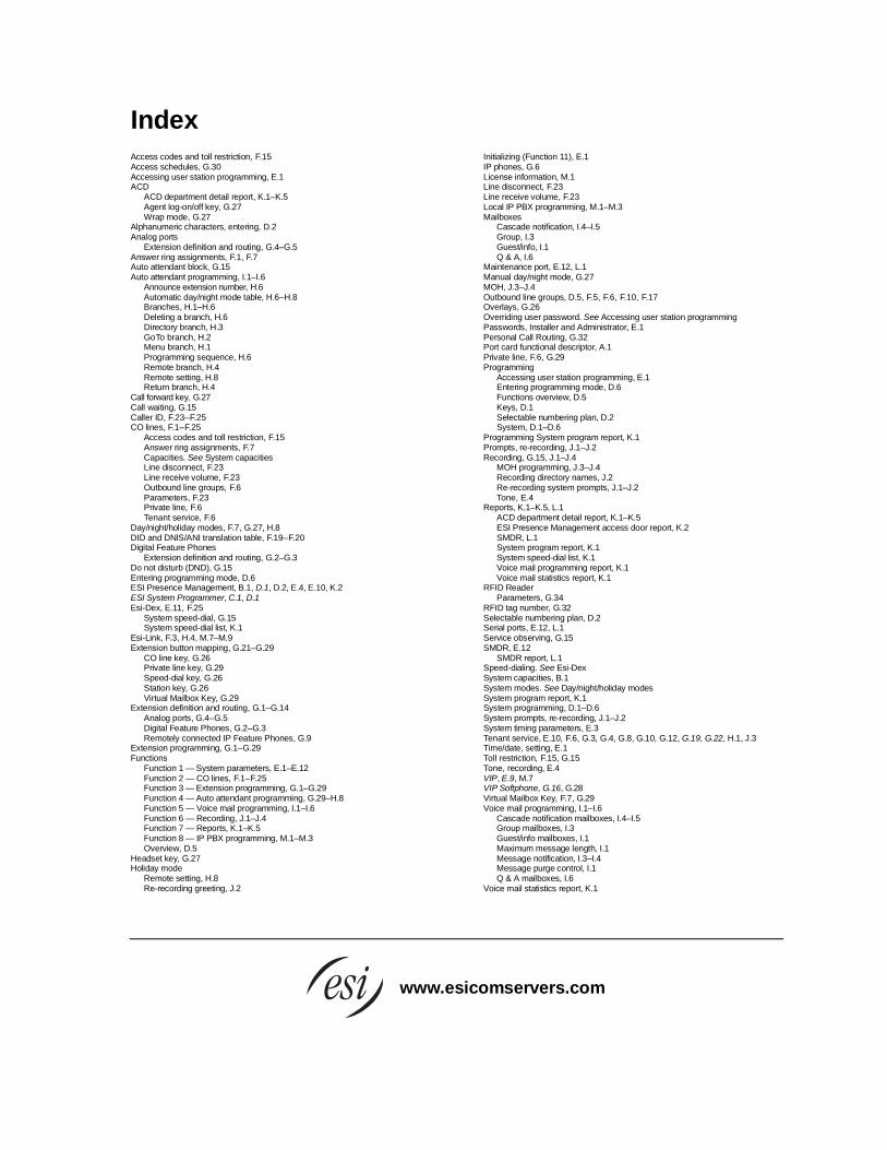
Index
Access codes and toll restriction, F.15 Access schedules, G.30 Accessing user station programming, E.1 ACD
ACD department detail report, K.1–K.5 Agent log-on/off key, G.27 Wrap mode, G.27
Alphanumeric characters, entering, D.2 Analog ports
Extension definition and routing, G.4–G.5 Answer ring assignments, F.1, F.7 Auto attendant block, G.15 Auto attendant programming, I.1–I.6
Announce extension number, H.6 Automatic day/night mode table, H.6–H.8 Branches, H.1–H.6 Deleting a branch, H.6 Directory branch, H.3 GoTo branch, H.2 Menu branch, H.1 Programming sequence, H.6 Remote branch, H.4 Remote setting, H.8 Return branch, H.4
Call forward key, G.27 Call waiting, G.15 Caller ID, F.23–F.25 CO lines, F.1–F.25
Access codes and toll restriction, F.15 Answer ring assignments, F.7 Capacities. See System capacities Line disconnect, F.23 Line receive volume, F.23 Outbound line groups, F.6 Parameters, F.23 Private line, F.6 Tenant service, F.6
Day/night/holiday modes, F.7, G.27, H.8 DID and DNIS/ANI translation table, F.19–F.20 Digital Feature Phones
Extension definition and routing, G.2–G.3 Do not disturb (DND), G.15 Entering programming mode, D.6 ESI Presence Management, B.1, D.1, D.2, E.4, E.10, K.2 ESI System Programmer, C.1, D.1 Esi-Dex, E.11, F.25
System speed-dial, G.15 System speed-dial list, K.1
Esi-Link, F.3, H.4, M.7–M.9 Extension button mapping, G.21–G.29
CO line key, G.26 Private line key, G.29 Speed-dial key, G.26 Station key, G.26 Virtual Mailbox Key, G.29
Extension definition and routing, G.1–G.14 Analog ports, G.4–G.5 Digital Feature Phones, G.2–G.3 Remotely connected IP Feature Phones, G.9
Extension programming, G.1–G.29 Functions
Function 1 — System parameters, E.1–E.12 Function 2 — CO lines, F.1–F.25 Function 3 — Extension programming, G.1–G.29 Function 4 — Auto attendant programming, G.29–H.8 Function 5 — Voice mail programming, I.1–I.6 Function 6 — Recording, J.1–J.4 Function 7 — Reports, K.1–K.5 Function 8 — IP PBX programming, M.1–M.3 Overview, D.5
Headset key, G.27 Holiday mode
Remote setting, H.8 Re-recording greeting, J.2
Initializing (Function 11), E.1 IP phones, G.6 License information, M.1 Line disconnect, F.23 Line receive volume, F.23 Local IP PBX programming, M.1–M.3 Mailboxes
Cascade notification, I.4–I.5 Group, I.3 Guest/info, I.1 Q & A, I.6
Maintenance port, E.12, L.1 Manual day/night mode, G.27 MOH, J.3–J.4 Outbound line groups, D.5, F.5, F.6, F.10, F.17 Overlays, G.26 Overriding user password. See Accessing user station programming Passwords, Installer and Administrator, E.1 Personal Call Routing, G.32 Port card functional descriptor, A.1 Private line, F.6, G.29 Programming
Accessing user station programming, E.1 Entering programming mode, D.6 Functions overview, D.5 Keys, D.1 Selectable numbering plan, D.2 System, D.1–D.6
Programming System program report, K.1 Prompts, re-recording, J.1–J.2 Recording, G.15, J.1–J.4
MOH programming, J.3–J.4 Recording directory names, J.2 Re-recording system prompts, J.1–J.2 Tone, E.4
Reports, K.1–K.5, L.1 ACD department detail report, K.1–K.5 ESI Presence Management access door report, K.2 SMDR, L.1 System program report, K.1 System speed-dial list, K.1 Voice mail programming report, K.1 Voice mail statistics report, K.1
RFID Reader Parameters, G.34
RFID tag number, G.32 Selectable numbering plan, D.2 Serial ports, E.12, L.1 Service observing, G.15 SMDR, E.12
SMDR report, L.1 Speed-dialing. See Esi-Dex System capacities, B.1 System modes. See Day/night/holiday modes System program report, K.1 System programming, D.1–D.6 System prompts, re-recording, J.1–J.2 System timing parameters, E.3 Tenant service, E.10, F.6, G.3, G.4, G.8, G.10, G.12, G.19, G.22, H.1, J.3 Time/date, setting, E.1 Toll restriction, F.15, G.15 Tone, recording, E.4 VIP, E.9, M.7 VIP Softphone, G.16, G.28 Virtual Mailbox Key, F.7, G.29 Voice mail programming, I.1–I.6
Cascade notification mailboxes, I.4–I.5 Group mailboxes, I.3 Guest/info mailboxes, I.1 Maximum message length, I.1 Message notification, I.3–I.4 Message purge control, I.1 Q & A mailboxes, I.6
Voice mail statistics report, K.1
www.esicomservers.com