esr 0620 - overhaul of gmg 158 exciter auxiliary generator · pdf filerailcorp engineering...
TRANSCRIPT
Engi
neer
ing
Stan
dard
Engineering Standard Rolling Stock
ESR 0620
OVERHAUL OF GMG 158 EXCITER AUXILIARY GENERATOR SET
Version 1.0
Issued June 2010
Owner: Chief Engineer Rolling Stock Approved by:
Stephen White,
Disclaimer This document was prepared for use on the RailCorp Network only. RailCorp makes no warranties, express or implied, that compliance with the contents of this document shall be sufficient to ensure safe systems or work or operation. It is the document user’s sole responsibility to ensure that the copy of the document it is viewing is the current version of the document as in use by RailCorp. RailCorp accepts no liability whatsoever in relation to the use of this document by any party, and RailCorp excludes any liability which arises in any manner by the use of this document. Copyright The information in this document is protected by Copyright and no part of this document may be reproduced, altered, stored or transmitted by any person without the prior consent of RailCorp.
Technical Specialist Rolling Stock Performance Standards,
Authorised by:
Michael Uhlig, Manager, Rolling Stock Access Integrity
Rolling Stock Access Integrity
UNCONTROLLED WHEN PRINTED Page 1 of 22
RailCorp Engineering Standard — Rolling Stock Overhaul of GMG 158 exciter auxiliary generator set ESR 0620
© Rail Corporation Page 2 of 22 Issued June 2010 UNCONTROLLED WHEN PRINTED Version 1.0
Document control
Revision Date Summary of change (RSS 0620) 1.0 August 2007 Based on TRS 1442 (ESR 0620) 1.0 June 2010 Reformatted and renumbered ESR 0620
Summary of changes from previous version
Summary of change Section NOTE – If the final document is small enough for the ‘Contents’ and ‘Document control’ to fit on one page remove the page break between the existing pages 2 and 3. HOWEVER if the ‘Document control’ page carries over to a second page separate pages must be used for ‘Contents’ and ‘Document control’
RailCorp Engineering Standard — Rolling Stock Overhaul of GMG 158 exciter auxiliary generator set ESR 0620
© Rail Corporation Page 3 of 22 Issued June 2010 UNCONTROLLED WHEN PRINTED Version 1.0
Contents
1 Scope..................................................................................................................................................5 2 General ...............................................................................................................................................5 3 Torque settings .................................................................................................................................5 4 Pre service/overhaul inspection ......................................................................................................6
4.1 Pre cleaning activity ..................................................................................................................6 4.2 Post cleaning activity.................................................................................................................6
5 Service procedures ...........................................................................................................................6 5.1 Armature and commutators.......................................................................................................6 5.2 Brushgear..................................................................................................................................7 5.3 Machine frame ..........................................................................................................................7 5.4 Bearings ....................................................................................................................................7 5.5 Fan ............................................................................................................................................7 5.6 Motor painting ...........................................................................................................................8
6 Post service test................................................................................................................................8 6.1 General......................................................................................................................................8
6.1.1 Continuous rating .........................................................................................................8 6.1.2 Rated voltage ...............................................................................................................8 6.1.3 Rated speed .................................................................................................................8 6.1.4 Maximum speed of the generator ................................................................................8 6.1.5 Direction of rotation ......................................................................................................8 6.1.6 Eccentricity of commutator ...........................................................................................9
6.2 Summary of tests to be performed on the generator ................................................................9 6.2.1 Resistance measurement ............................................................................................9 6.2.2 Insulation resistance test 1...........................................................................................9 6.2.3 Direction of rotation test ...............................................................................................9 6.2.4 Temperature rise and vibration test .............................................................................9 6.2.5 Overspeed test .............................................................................................................9 6.2.6 Insulation resistance test 2.........................................................................................10 6.2.7 Commutator roundness..............................................................................................10 6.2.8 Brush pressure ...........................................................................................................10
6.3 Instrumentation .......................................................................................................................10 6.4 Documentation ........................................................................................................................10
7 Overhaul/rewind procedure............................................................................................................10 7.1 General....................................................................................................................................10 7.2 Armature overhaul...................................................................................................................11 7.3 Brushgear................................................................................................................................11 7.4 Machine frame ........................................................................................................................12 7.5 Fan ..........................................................................................................................................12 7.6 Machine painting .....................................................................................................................12
8 Post overhaul/rewind test...............................................................................................................13 8.1 General....................................................................................................................................13
8.1.1 Continuous rating .......................................................................................................13
RailCorp Engineering Standard — Rolling Stock Overhaul of GMG 158 exciter auxiliary generator set ESR 0620
© Rail Corporation Page 4 of 22 Issued June 2010 UNCONTROLLED WHEN PRINTED Version 1.0
8.1.2 Rated voltage .............................................................................................................13 8.1.3 Rated speed ...............................................................................................................13 8.1.4 Maximum speed of the exciter-auxiliary generator ....................................................13 8.1.5 Direction of rotation ....................................................................................................13 8.1.6 Eccentricity of commutator .........................................................................................13
8.2 Summary of tests on the exciter-auxiliary generator ..............................................................13 8.2.1 Resistance measurement ..........................................................................................13 8.2.2 Insulation resistance test 1.........................................................................................14 8.2.3 Direction of rotation test .............................................................................................14 8.2.4 Temperature rise and vibration test ...........................................................................14 8.2.5 Overspeed test ...........................................................................................................14 8.2.6 Commutator roundness..............................................................................................14 8.2.7 Brush pressure ...........................................................................................................14
8.3 Instrumentation .......................................................................................................................14 8.4 Documentation ........................................................................................................................14
9 48 class locomotive GMG 158 exciter-auxiliary generator .........................................................15 9.1 Pre service/overhaul inspection specification .........................................................................15
9.1.1 Armature.....................................................................................................................15 9.1.2 Fields and interpoles ..................................................................................................15
9.2 Service/rewind specification....................................................................................................15 9.2.1 Armature and commutator .........................................................................................15 9.2.2 Brushgear...................................................................................................................15 9.2.3 Bearings (approved)...................................................................................................15
9.3 Post service testing specification ............................................................................................16 9.3.1 Resistance measurement ..........................................................................................16 9.3.2 Insulation resistance 10 M Ohms @ 90°C (min.).......................................................16 9.3.3 Temperature rise and vibration test ...........................................................................16
10 Reference standards.......................................................................................................................16 10.1 RailCorp standards .................................................................................................................16 10.2 Alco standards ........................................................................................................................16 10.3 Australian and British standards .............................................................................................16 10.4 Drawings .................................................................................................................................17 10.5 Other standards ......................................................................................................................17
Appendix A Drawing 004-653, auxiliary electrical machines flow chart..................................18 Appendix B - Torque charts ................................................................................................................21
RailCorp Engineering Standard — Rolling Stock Overhaul of GMG 158 exciter auxiliary generator set ESR 0620
1 Scope This standard sets minimum technical requirements for the inspection, overhaul and testing of exciter-auxiliary generators used in 48 class diesel electric locomotives.
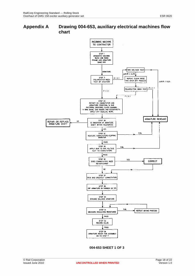
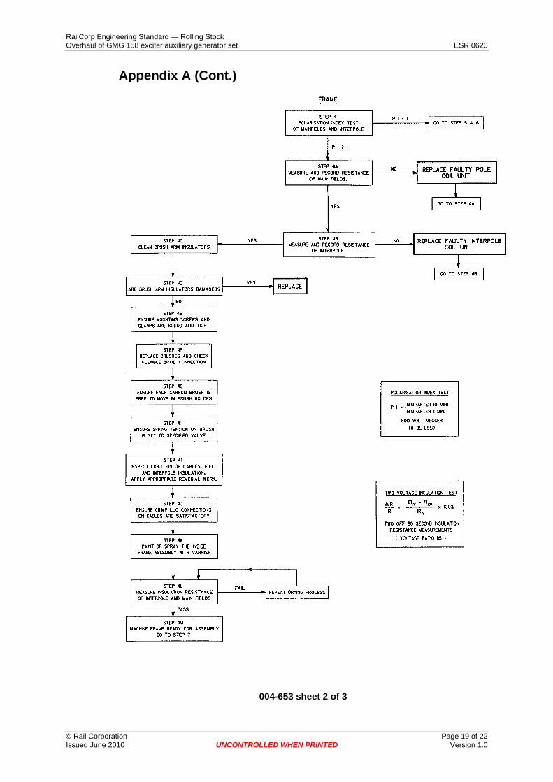
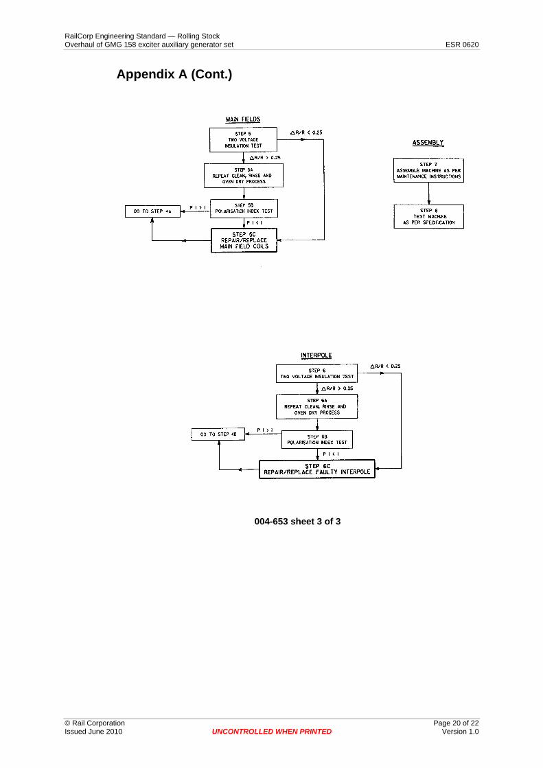
2 General It is to be used in conjunction with the Manufacturer's Maintenance Instructions, drawings and technical information, referenced herein, and with drawing 004-653, Auxiliary Electrical Machines Service Flow Chart. See Appendix A.
The goal of this specification is to provide overhauled and tested exciter-auxiliary generators which will operate at the specified performance levels for a period of not less than eight (8) years. However with new insulation, commutators and bearings they should operate at specified performance levels for a period of not less than twelve (12) years, supported only by scheduled maintenance programs
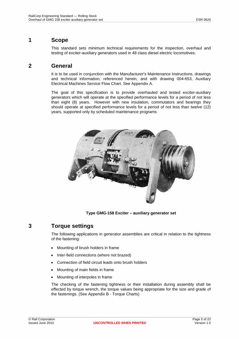
Type GMG-158 Exciter – auxiliary generator set
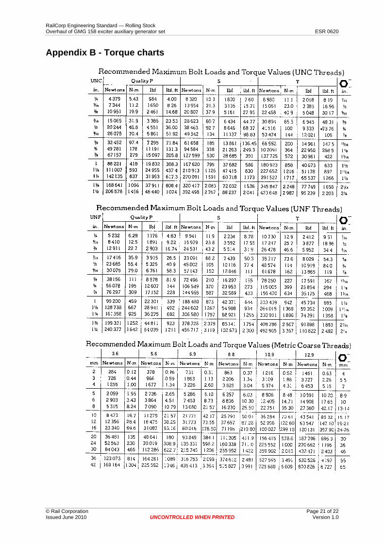
3 Torque settings The following applications in generator assemblies are critical in relation to the tightness of the fastening:
• Mounting of brush holders in frame
• Inter-field connections (where not brazed)
• Connection of field circuit leads onto brush holders
• Mounting of main fields in frame
• Mounting of interpoles in frame
The checking of the fastening tightness or their installation during assembly shall be effected by torque wrench, the torque values being appropriate for the size and grade of the fastenings. (See Appendix B - Torque Charts)
© Rail Corporation Page 5 of 22 Issued June 2010 UNCONTROLLED WHEN PRINTED Version 1.0
RailCorp Engineering Standard — Rolling Stock Overhaul of GMG 158 exciter auxiliary generator set ESR 0620
© Rail Corporation Page 6 of 22 Issued June 2010 UNCONTROLLED WHEN PRINTED Version 1.0
4 Pre service/overhaul inspection If it is not visually obvious that a rewind is required the following checks shall be carried out and the results recorded. Any non-conformance with the specification shall be reported to the Engineer to determine further action.
4.1 Pre cleaning activity The following inspection is to be carried out prior to the exciter-auxiliary generator being dismantled, cleaned of all dirt and grease.
Measure the position of the brush holders relative to the commutator riser bars and face.
4.2 Post cleaning activity The following inspections are to be carried out after the exciter-auxiliary generator has been dismantled, cleaned of all dirt and grease, immersion rinsed (only if required to achieve two volt and PI test standards) and oven dried.
• Visually check commutators for any bar pattern, grooving, high bars, high mica or physical damage.
• Examine the armature insulation for charring, cracking and physical damage.
• Examine glass or wire banding for physical damage.
• Measure diameter of commutators to ensure they are above condemning size.
• Measure commutators for eccentricity.
• Measure armature winding resistances.
• Measure the resistance of the generator fields.
• Measure resistance of the interpole coils.
• Measure insulation resistances as per Auxiliary Electrical Machines Service Flow Chart, SRA Drawing 004-653. See Appendix A.
• Apply surge test and bar-to-bar comparison test to commutators to check for open or short circuited coils.
• Check armature shaft for straightness, size (including 4 points on the bearing seat for ovality or taper, length of shaft overall, and critical sections) and surface integrity
• Examine the armature for any physical damage.
5 Service procedures Service work shall generally be in accordance with Manufacturer's Maintenance Manual and SRA drawing 004-653 with particular attention being given to the following:
5.1 Armature and commutators • Inspect for indication of high or loose bars and take corrective action as necessary.
• Inspect V-ring bands and riser bars for any flashover damage and correct.
• Resurface the commutators (where needed) with the minimum cut to ensure surface integrity and roundness.
• Undercut the micas to width 0.75 mm and depth 1.2 mm, both commutators.
• Chamfer the commutators bar edges (45°, 0.2 - 0.4mm across face).
RailCorp Engineering Standard — Rolling Stock Overhaul of GMG 158 exciter auxiliary generator set ESR 0620
© Rail Corporation Page 7 of 22 Issued June 2010 UNCONTROLLED WHEN PRINTED Version 1.0
• Dip armature in varnish or VPI (compatible with existing insulation) where generators have been recovered by rinsing or there has been visible damage to the insulation.
• Dynamically balance armature. Balance quality grade 2.5 (AS 3709; ISO 1940/1).
• Apply red air drying insulating varnish to armature (shaft and commutators to be suitably masked before applying varnish).
5.2 Brushgear • Remove brush holders and check insulators for any visible damage (cracks, chips or
tracking).Replace any damaged insulators.
• Inspect for any flashover deposits on brush holders and correct.
• Ensure brush holders are not deformed.
• Sand blast brush holders. Brushways and insulators to be suitably masked.
• Set brush spring pressure (1.35 ± 0.1 Kg), both ends.
• Ensure mounting screws and clamps are sound and correctly torqued (see clause 3).
• Ensure brushgear alignment is parallel to commutator centre line.
• Ensure spacing of brush holders is correct.
• Fit new brushes and ensure free movement. Refer Drawing 407-350.
• Inspect braiding of brushes and ensure tightness of brush terminal connections. (Braiding must be positioned to allow free movement of hammers).
5.3 Machine frame • Ensure connections are sound and correctly torqued (see clause 3).
• Ensure all mounting bolts and nuts are correctly torqued (see clause 3).
• Ensure main field and interpole insulation is in good condition. Apply red air drying insulation varnish to inside assembly.
• Inspect cables, crimp lugs and markers for any signs of mechanical or electrical damage and replace any defective parts.
• Internal field leads must be securely bound to the bracing staples. Replace any loose or defective binding. (Cable ties are not permitted for this purpose.)
• Inspect bearing housing and seals for excess wear as indicated in relevant data and restore where necessary.
• Inspect condition of cable cleats. Replace if damaged.
• Ensure inspection cover components including locating lugs, latching mechanisms, springs, bolts and sealing strips will provide correct securing of covers and sealing for cooling air.
5.4 Bearings • New bearings shall be provided and fitted by the Contractor. Acceptable bearings are
listed in the specification.
5.5 Fan • Inspect fan for evidence of physical damage. Correct or replace as required.
RailCorp Engineering Standard — Rolling Stock Overhaul of GMG 158 exciter auxiliary generator set ESR 0620
© Rail Corporation Page 8 of 22 Issued June 2010 UNCONTROLLED WHEN PRINTED Version 1.0
• Inspect mounting holes for deformation or physical damage. Correct or replace as required.
• Inspect fan blades for physical damage and/or wear. Correct or replace as required.
• Balance fan as per specification.
5.6 Motor painting After stripping off old paint work all exciter-auxiliary generators shall be painted with 1 coat of suitable primer and 1 coat of enamel paint - which shall be approved under GPC-E-24. The colour will be nominated by the Engineer and shall comply with AS2700.
Note: Areas to be masked shall include:
• Manufacturer's data plate
• Leads
• Commutator inspection hatches.
• Shafts.
• Fan exhaust.
• Terminal box.
6 Post service test
6.1 General This procedure covers the performance testing of exciter-auxiliary generators used on 48 class diesel electric locomotives.
The definitions applicable to this standard are:
6.1.1 Continuous rating The rating that corresponds to a load that the exciter-auxiliary generator can withstand on the test for an unlimited period, without exceeding the limits of temperature rise as given in BS173, Clause 31. The test being started with the machine cold (see BS 173, Clause 34).
6.1.2 Rated voltage The specified value of the voltage at the terminals of the machine.
6.1.3 Rated speed The speed corresponding to the manufacturer's guarantee.
6.1.4 Maximum speed of the generator The maximum rotational speed of the exciter-auxiliary generator corresponding to the maximum service supply voltage.
6.1.5 Direction of rotation The direction of rotation of the armature when facing the pulley end of the generator.
RailCorp Engineering Standard — Rolling Stock Overhaul of GMG 158 exciter auxiliary generator set ESR 0620
© Rail Corporation Page 9 of 22 Issued June 2010 UNCONTROLLED WHEN PRINTED Version 1.0
6.1.6 Eccentricity of commutator Out of round measured over the full circumference of the commutators.
6.2 Summary of tests to be performed on the generator The test program shall, in principle, be carried out in accordance with the requirements of BS173.1980.
6.2.1 Resistance measurement Measure the resistance value of all windings in the main field, the interpoles and the armature windings.
If the ammeter and voltmeter method is used for the measurement of resistance, the current used shall be of a value such as to obtain a suitable accuracy of measurement, whilst being low enough to neither cause the armature to start through the effect of residual flux nor influence the temperature rise.
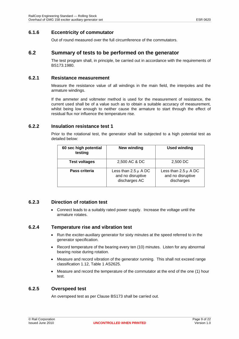
6.2.2 Insulation resistance test 1 Prior to the rotational test, the generator shall be subjected to a high potential test as detailed below:
60 sec high potential testing
New winding Used winding
Test voltages 2,500 AC & DC 2,500 DC
Pass criteria Less than 2.5 μ A DC and no disruptive discharges AC
Less than 2.5 μ A DC and no disruptive
discharges
6.2.3 Direction of rotation test • Connect leads to a suitably rated power supply. Increase the voltage until the
armature rotates.
6.2.4 Temperature rise and vibration test • Run the exciter-auxiliary generator for sixty minutes at the speed referred to in the
generator specification.
• Record temperature of the bearing every ten (10) minutes. Listen for any abnormal bearing noise during rotation.
• Measure and record vibration of the generator running. This shall not exceed range classification 1.12, Table 1 AS2625.
• Measure and record the temperature of the commutator at the end of the one (1) hour test.
6.2.5 Overspeed test An overspeed test as per Clause BS173 shall be carried out.
RailCorp Engineering Standard — Rolling Stock Overhaul of GMG 158 exciter auxiliary generator set ESR 0620
© Rail Corporation Page 10 of 22 Issued June 2010 UNCONTROLLED WHEN PRINTED Version 1.0
6.2.6 Insulation resistance test 2 After the rotational test, the generator shall be subjected to a high potential test as follows:
Error! Objects cannot be created from editing field codes.
Compare results with Insulation resistance test 1 (6.2.2).
6.2.7 Commutator roundness Position dial gauge to touch the commutator surface. Rotate armature slowly by hand and measure the commutator eccentricity. Record values on test sheet.
6.2.8 Brush pressure Use a suitable instrument to test the pressure of all brush springs (1.35 kg ± 0.1 kg).
6.3 Instrumentation The serial numbers of all instruments and meters used to perform the tests outlined in section 6.2 shall be recorded, together with the date of their most recent calibration check.
6.4 Documentation The recorded measurements shall be entered in dated test report sheets and returned with the machine.
7 Overhaul/rewind procedure
7.1 General This part of the Specification covers the rewind/overhaul of the exciter-auxiliary generator. The work shall incorporate rewinding the armature, correcting generator frame and fields and installation of the following new components:
• Commutator (new or rebuilt)
• Armature bearing
• Brushes
The following shall be inspected for suitability for further duty and restored to service specifications. If beyond repair they shall be replaced with new components:
• Brush holders
• Commutator inspection covers
• Leads and cleats
• Fan
The commutators, fields and bearings removed from generators and replaced shall be returned to the Purchaser.
RailCorp Engineering Standard — Rolling Stock Overhaul of GMG 158 exciter auxiliary generator set ESR 0620
© Rail Corporation Page 11 of 22 Issued June 2010 UNCONTROLLED WHEN PRINTED Version 1.0
7.2 Armature overhaul • Remove bearings and commutators.
• Strip the armature of coils and insulation.
• Shafts suitable for resizing may be repaired by Gas Metal Arc Welding - GMAW and machined to specified dimensions. The welding procedure shall be strictly in accordance with AS1554.1, the electrodes shall be type ESD2 to AS 2717.1 and the gas shall be Argoshield 51. This procedure may be utilised for restoration requiring weld deposits to 6 mm. Repairs exceeding 6 mm deposit shall be referred to the Engineer. All welding shall comply with Australian Standards.
• Flux test the core to ensure no shorts or damage exist in the laminations. Defective cores are to be referred to the Engineer.
• Fit new or rebuilt fully seasoned commutators.
• Rewind armature with new main coils insulated to Classification 180 of AS 2768.
• TIG weld/resistance braze coil ends to riser bars.
• VPI the armature with Isonel 772 varnish.
• Oven dry.
• Ensure commutator nuts are secure after drying.
• Resurface the commutators with minimum cut to ensure surface integrity and roundness.
• Undercut commutator micas to width 0.75mm and depth 1.2mm, both commutators.
• Chamfer commutator bar edges (45°, 0.2 to 0.4 mm across face).
• Dynamically balance the armature to the specified limit. Balance quality grade 2.5 (AS 3709; ISO 1940/1)
• Apply red air drying insulation varnish to armature (shaft and commutators to be suitably masked before applying varnish).
• Cleaning, drying, rewinding, testing and banding throughout the process shall be in accordance with the Manufacturer's Maintenance Manuals for original equipment or previously approved replacement, (eg. glass band).
• Fit new armature shaft bearings, as approved in the generator specification.
• Fit qualified fan.
7.3 Brushgear • Remove brush holders and check insulators for any visible damage (cracks, chips,
tracking etc). Replace any damaged insulators.
• Inspect for any flashover deposits on brush holders and correct.
• Sand blast brush holders. (Brushways and insulators to be suitably masked.)
• Replace any deformed brush holders.
• Ensure mounting screws and clamps are sound and correctly torqued (see clause 3).
• Ensure brushgear alignment is parallel to commutator centre line.
• Ensure spacing of brush holders is correct.
• Fit new brushes and ensure they move freely. Refer Drawing 407-350
• Check braiding of brushes and ensure tightness of brush terminal connections. (Braiding must be positioned to allow free movement of hammers.)
RailCorp Engineering Standard — Rolling Stock Overhaul of GMG 158 exciter auxiliary generator set ESR 0620
© Rail Corporation Page 12 of 22 Issued June 2010 UNCONTROLLED WHEN PRINTED Version 1.0
• Set brush pressure (1.35 ± 0.1 Kg), both ends.
7.4 Machine frame • Thoroughly clean the generator inside and outside, preferably by an ultrasonic
process that does not utilise a detergent. Alternatively a spray wash may be used in conjunction with a detergent incorporating a non-ionic surfactant wetting agent and such detergent shall have the Engineer's written approval. generators so cleaned shall have all traces of detergent removed by a clean water/steam rinse.
• Remove main and interpole coils and pole pieces.
• Inspect insulation quality. Where required reinsulate to ensure suitability for nominated duty requirements. Reinsulation shall be with an approved asbestos-free system incorporating B stage epoxy rich materials to classification 180 of AS2768.
• Pot the coils onto the pole pieces.
• Fit all coils into the frame and connect. Ensure all mounting and connect bolts and nuts are correctly torqued and new spring washers are used (see clause 3).
• Inspect cables, crimp lugs and markers, correct any signs of mechanical or electrical damage and replace any defective parts.
• Internal field leads must be securely bound to the bracing staples. Replace any loose or defective binding. (Cable ties are not permitted for this purpose.)
• Inspect bearing housing and seals for excess wear as indicated in exciter-auxiliary generator data and restore where necessary.
• Inspect condition of cable cleats. Replace if damaged.
• Spray the interior of the machine with red air drying insulating varnish.
• Bearings
New bearings shall be provided and fitted by the Contractor. Acceptable bearings are listed in the generator specification.
7.5 Fan • Inspect fan and blades for evidence of physical damage or excessive. Restore to
serviceable condition.
• Inspect mounting holes for deformation or physical damage.
• Dynamically balance fan as per specification
7.6 Machine painting After stripping of old paintwork all generators shall be painted with 1 coat of suitable primer and 1 coat of enamel paint - which shall be approved under GPC-E-24. The colour will be nominated by the Engineer and shall comply with AS 2700.
Note: Areas to be masked shall include:
• Manufacturer's data plate
• Leads
• Commutator inspection hatches
• Shaft
• Fan exhaust
RailCorp Engineering Standard — Rolling Stock Overhaul of GMG 158 exciter auxiliary generator set ESR 0620
© Rail Corporation Page 13 of 22 Issued June 2010 UNCONTROLLED WHEN PRINTED Version 1.0
• Terminal box
8 Post overhaul/rewind test
8.1 General This procedure covers the performance testing of direct current exciter-auxiliary generator used on 48 class diesel electric locomotives.
The definitions applicable to this standard are:
8.1.1 Continuous rating The rating that corresponds to a load that the exciter-auxiliary generator can withstand on the test for an unlimited period, without exceeding the limits of temperature rise is given in BS173, Clause 31, the test being started with the machine cold (see BS173, Clause 34).
8.1.2 Rated voltage The specified value of the voltage at the terminals of the machine.
8.1.3 Rated speed The speed corresponding to the manufacturer's guarantee.
8.1.4 Maximum speed of the exciter-auxiliary generator The maximum rotational speed of the exciter-auxiliary generator corresponding to the maximum supply voltage of the vehicle.
8.1.5 Direction of rotation The direction of rotation of the armature when facing the pulley end of the generator.
8.1.6 Eccentricity of commutator Out of round measured over the full circumference of the commutators.
8.2 Summary of tests on the exciter-auxiliary generator The test program shall, in principle, be carried out in accordance with the requirements of BS 173.1980.
8.2.1 Resistance measurement Measure the resistance value of the main fields, the interpoles and the armature windings.
If the ammeter and voltmeter method is used for the measurement of resistance, the current used shall be of a value such as to obtain a suitable accuracy of measurement, whilst being low enough to neither cause the armature to start through the effect of residual flux nor influence the temperature rise.
RailCorp Engineering Standard — Rolling Stock Overhaul of GMG 158 exciter auxiliary generator set ESR 0620
© Rail Corporation Page 14 of 22 Issued June 2010 UNCONTROLLED WHEN PRINTED Version 1.0
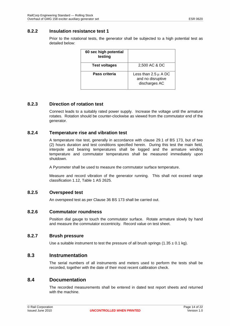
8.2.2 Insulation resistance test 1 Prior to the rotational tests, the generator shall be subjected to a high potential test as detailed below:
60 sec high potential testing
Test voltages 2,500 AC & DC
Pass criteria Less than 2.5 μ A DC and no disruptive discharges AC
8.2.3 Direction of rotation test Connect leads to a suitably rated power supply. Increase the voltage until the armature rotates. Rotation should be counter-clockwise as viewed from the commutator end of the generator.
8.2.4 Temperature rise and vibration test A temperature rise test, generally in accordance with clause 29.1 of BS 173, but of two (2) hours duration and test conditions specified herein. During this test the main field, interpole and bearing temperatures shall be logged and the armature winding temperature and commutator temperatures shall be measured immediately upon shutdown.
A Pyrometer shall be used to measure the commutator surface temperature.
Measure and record vibration of the generator running. This shall not exceed range classification 1.12, Table 1 AS 2625.
8.2.5 Overspeed test An overspeed test as per Clause 36 BS 173 shall be carried out.
8.2.6 Commutator roundness Position dial gauge to touch the commutator surface. Rotate armature slowly by hand and measure the commutator eccentricity. Record value on test sheet.
8.2.7 Brush pressure Use a suitable instrument to test the pressure of all brush springs (1.35 ± 0.1 kg).
8.3 Instrumentation The serial numbers of all instruments and meters used to perform the tests shall be recorded, together with the date of their most recent calibration check.
8.4 Documentation The recorded measurements shall be entered in dated test report sheets and returned with the machine.
RailCorp Engineering Standard — Rolling Stock Overhaul of GMG 158 exciter auxiliary generator set ESR 0620
© Rail Corporation Page 15 of 22 Issued June 2010 UNCONTROLLED WHEN PRINTED Version 1.0
9 48 class locomotive GMG 158 exciter-auxiliary generator
9.1 Pre service/overhaul inspection specification
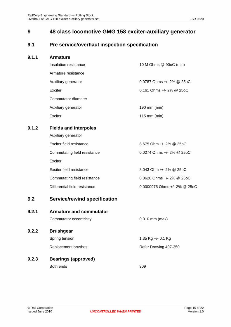
9.1.1 Armature Insulation resistance 10 M Ohms @ 90oC (min)
Armature resistance
Auxiliary generator 0.0787 Ohms +/- 2% @ 25oC
Exciter 0.161 Ohms +/- 2% @ 25oC
Commutator diameter
Auxiliary generator 190 mm (min)
Exciter 115 mm (min)
9.1.2 Fields and interpoles Auxiliary generator
Exciter field resistance 8.675 Ohm +/- 2% @ 25oC
Commutating field resistance 0.0274 Ohms +/- 2% @ 25oC
Exciter
Exciter field resistance 8.043 Ohm +/- 2% @ 25oC
Commutating field resistance 0.0620 Ohms +/- 2% @ 25oC
Differential field resistance 0.0000975 Ohms +/- 2% @ 25oC
9.2 Service/rewind specification
9.2.1 Armature and commutator Commutator eccentricity 0.010 mm (max)
9.2.2 Brushgear Spring tension 1.35 Kg +/- 0.1 Kg
Replacement brushes Refer Drawing 407-350
9.2.3 Bearings (approved) Both ends 309
RailCorp Engineering Standard — Rolling Stock Overhaul of GMG 158 exciter auxiliary generator set ESR 0620
© Rail Corporation Page 16 of 22 Issued June 2010 UNCONTROLLED WHEN PRINTED Version 1.0
9.3 Post service testing specification
9.3.1 Resistance measurement Auxiliary generator
Armature ................. Ohms
Exciter field ................. Ohms
Commutating field .................Ohms
Exiter
Armature ................. Ohms
Exciter field ................. Ohms
Commutating field .................Ohms
Differential field .................Ohms
9.3.2 Insulation resistance 10 M Ohms @ 90°C (min.)
9.3.3 Temperature rise and vibration test Speed 1950 rpm
Vibration 0.1 mm/sec (max.)
10 Reference standards
10.1 RailCorp standards RSS 0550 Overhaul of 48 class locomotive engine assembly
10.2 Alco standards MI-2006-A Exciter-auxiliary generators types 5GMG 139, 144 & 158
10.3 Australian and British standards AS 1554.1 SAA Structural steel welding code. welding of steel structures
AS 2625 Rotating & reciprocating machinery – mechanical vibration
AS 2700 Colour standards for general purpose
AS 2717.1 Welding electrodes - gas metal arc ferritic steel electrodes
AS 2768 Electrical insulating materials, evaluation and classification based on thermal endurance
AS 3709/ISO 1940 Vibration & shock – balance quality of rotating rigid bodies.
BS 173 Methods of specifying performance of rotating electrical machines for rail and road vehicles
RailCorp Engineering Standard — Rolling Stock Overhaul of GMG 158 exciter auxiliary generator set ESR 0620
© Rail Corporation Page 17 of 22 Issued June 2010 UNCONTROLLED WHEN PRINTED Version 1.0
10.4 Drawings 004-653 Auxiliary electrical generator service flow chart
407-350 43, 44 Mk1, 442Mk1 classes G.E. aux. generator brush & 442 Mk1, 48 Mk1 class G.E. exciter brush
10.5 Other standards GPC-E-24 Full gloss oil and petrol resistant enamel
RailCorp Engineering Standard — Rolling Stock Overhaul of GMG 158 exciter auxiliary generator set ESR 0620
Appendix A Drawing 004-653, auxiliary electrical machines flow chart
004-653 SHEET 1 OF 3
© Rail Corporation Page 18 of 22 Issued June 2010 UNCONTROLLED WHEN PRINTED Version 1.0
RailCorp Engineering Standard — Rolling Stock Overhaul of GMG 158 exciter auxiliary generator set ESR 0620
Appendix A (Cont.)
004-653 sheet 2 of 3
© Rail Corporation Page 19 of 22 Issued June 2010 UNCONTROLLED WHEN PRINTED Version 1.0
RailCorp Engineering Standard — Rolling Stock Overhaul of GMG 158 exciter auxiliary generator set ESR 0620
Appendix A (Cont.)
004-653 sheet 3 of 3
© Rail Corporation Page 20 of 22 Issued June 2010 UNCONTROLLED WHEN PRINTED Version 1.0
RailCorp Engineering Standard — Rolling Stock Overhaul of GMG 158 exciter auxiliary generator set ESR 0620
Appendix B - Torque charts
© Rail Corporation Page 21 of 22 Issued June 2010 UNCONTROLLED WHEN PRINTED Version 1.0
RailCorp Engineering Standard — Rolling Stock Overhaul of GMG 158 exciter auxiliary generator set ESR 0620
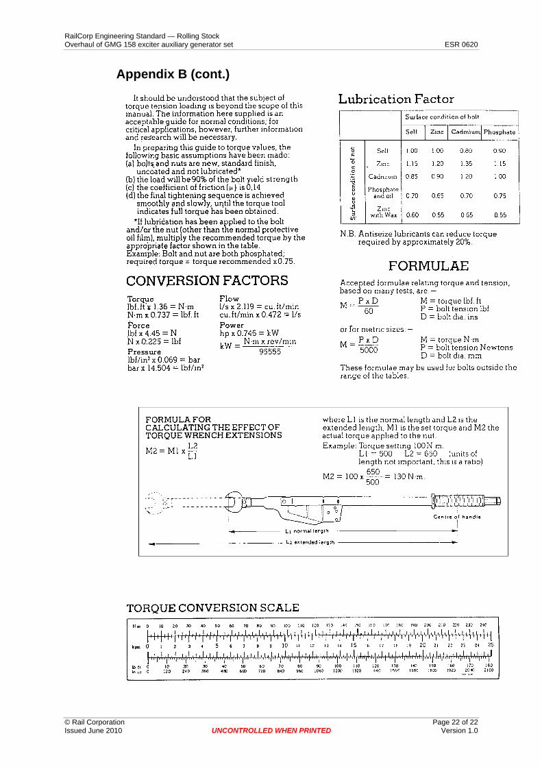
Appendix B (cont.)
© Rail Corporation Page 22 of 22 Issued June 2010 UNCONTROLLED WHEN PRINTED Version 1.0