ess cryogenic system design philipp arnold section leader cryogenics 6 th internation workshop on...
TRANSCRIPT
ESS Cryogenic System Design
Philipp ArnoldSection Leader Cryogenics
www.europeanspallationsource.se6th Internation Workshop on Cryogenic Operations
November 10-12, 2014

2
View of the Southwest in 2025
• Max IV – a national research facility, under construction, opens up in 2015
• Science City – a new part of town
Lund(113 500)
Malmö(309 000) Copenhagen
(1 200 000)
MAX IV
ESS

3
Outline
1) System Overview
2) Cryogenic Design Choices
– Plant and process arrangement– Cryomodule cooling at 2K– ACCP plant staging– LN2 pre-cooling– Helium storage– Heat recovery– Control system
3) Procurement and Tender Evaluation
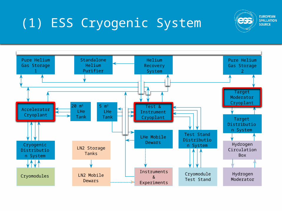
(1) ESS Cryogenic System
Pure Helium Gas Storage 1
20 m3 LHe Tank
Standalone Helium Purifier
Helium Recovery System
Pure Helium Gas Storage 2
AcceleratorCryoplant
Test & Instrument Cryoplant
5 m3 LHe Tank
Target ModeratorCryoplant
LHe Mobile Dewars
Test Stand Distribution
System
Instruments & Experiments
LN2 Storage Tanks
LN2 Mobile Dewars
Cryogenic Distribution
System
Cryomodules Cryomodule Test Stand
Target Distribution
System
Hydrogen Circulation Box
Hydrogen Moderator

5
(2.1) Plant and process arrangement
Combination of warm and cold sub-atmospheric compression for ACCP
- High flexibility for load adaption- Optimal overall efficiency
1 coldbox building, 1 compressor building,1 plant per job
- Highest space and CAPEX savings- Schedule, budgeting and technical requirements- Maintainability
Only warm sub-atmospheric compression for TICP

6
(2.2) Cryomodule cooling at 2K
Production of 2 K helium in 2 K heat exchanger and a sub-sequent Joule-Thomson valve in each of the cryomodule–valve box assemblies
- Heat load on CDS only on 4.5K, not 2K helium
- independent warm-up / maintenance / cool-down of single cryomodules while the rest of the system is maintained in cold condition
7
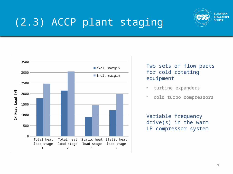
(2.3) ACCP plant staging
Total heat load stage 1
Total heat load stage 2
Static heat load stage 1
Static heat load stage 2
0
500
1000
1500
2000
2500
3000
3500
excl. margin incl. margin
2K H
eat L
oad
[W]
Two sets of flow parts for cold rotating equipment
- turbine expanders
- cold turbo compressors
Variable frequency drive(s) in the warm LP compressor system
8
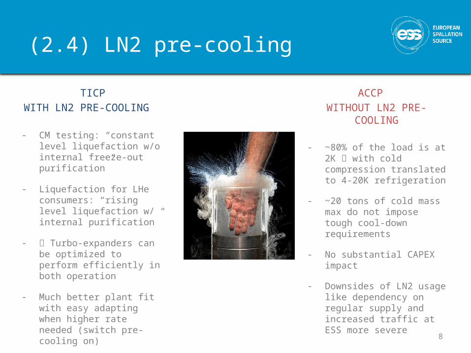
(2.4) LN2 pre-cooling
TICPWITH LN2 PRE-COOLING
- CM testing: “constant level liquefaction w/o internal freeze-out purification”
- Liquefaction for LHe consumers: “rising level liquefaction w/ internal purification”
- Turbo-expanders can be optimized to perform efficiently in both operation
- Much better plant fit with easy adapting when higher rate needed (switch pre-cooling on)
ACCP WITHOUT LN2 PRE-COOLING
- ~80% of the load is at 2K with cold compression translated to 4-20K refrigeration
- ~20 tons of cold mass max do not impose tough cool-down requirements
- No substantial CAPEX impact
- Downsides of LN2 usage like dependency on regular supply and increased traffic at ESS more severe

9
(2.5) Helium Storage
12
3
(1) Helium inventory in CMs and CDS ~ 2 tons during normal operation
(2) 20 m3 LHe tank as second fill– Speed up re-cool-down
– Facilitate helium management in transient modes
(3) 16 x 60 m3 warm tanks – Store helium when accelerator warm
– A little more required for warm parts of ACCP and higher helium inventory during 4.5K standby mode / cool-down
NO CD0
500
1000
1500
2000
2500
Helium mass in CMs & CDS w/o shield[kg]
Vapour He-lium
Liquid He-lium

10
(2.6) Heat Recovery
• No elevated oil or helium temperatures out of compressor suppliers specs
• Dedicated cooling water circuit for cryoplant (quality constraints of available cooling water in the building)
• Slow temperature control on cooling water side, fast temperature control on oil side
• Cooler design state of the art e.g. for Kaeser compressors
• Cooling function has priority over heat recovery return
Compr. motor
Middle temperature
Return
Middle temperature
Supply
Oil vessel
Helium compressor
Helium cooler
Oil cooler
He to fine oil removal
He from cold box
High temperature
Return
Middle temperature
Return
25C
25C
27C
27C
27C
39C
85C
85C90C
32C
90C
32C
83C
37C
11
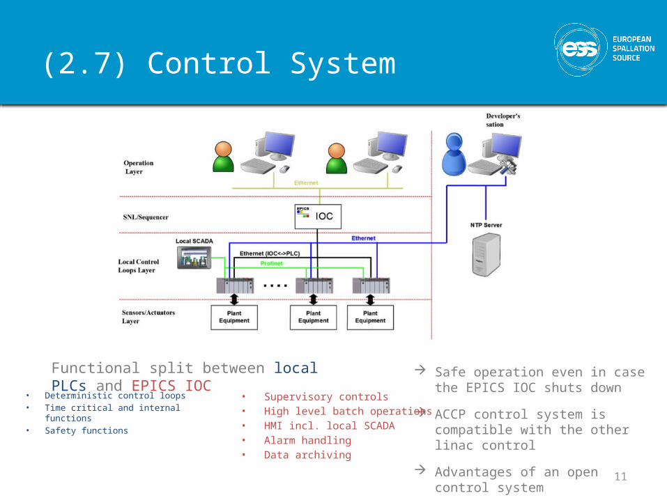
(2.7) Control System
Safe operation even in case the EPICS IOC shuts down
ACCP control system is compatible with the other linac control
Advantages of an open control system
Functional split between local PLCs and EPICS IOC
• Deterministic control loops • Time critical and internal functions• Safety functions
• Supervisory controls • High level batch operations• HMI incl. local SCADA• Alarm handling • Data archiving
12
(3) How do we get what we want?
Procurement procedures open, restricted, negotiated, competitive dialogue
Scope split clear interfaces (also during different phases of installation)
complex systems (rather one integrator) vs. simple systems
Small yet relevant qualitative part in the tender evaluation verifiable with proposal
Thorough acceptance testing Possibly incentive part for consumption
Sincere and transparent procurement process
Thank you for your attention