essentia project artica platform no frost 60 cm...
TRANSCRIPT

0
Essentia Project
Artica Platform
No Frost 60 cm Appliances
2011
EventCa’Maiano, May 2011
Presenter
Piotr Kelm
Francesco Nieli

Legend and User Interface
Legend
MID Indesit Interface(SQG_CL_29)
MID H/A Interface(SQG_CL_30)
Entry Interface (SQG_CL_28)
THR3 Interface (SQG_CL_32)

2
Functions
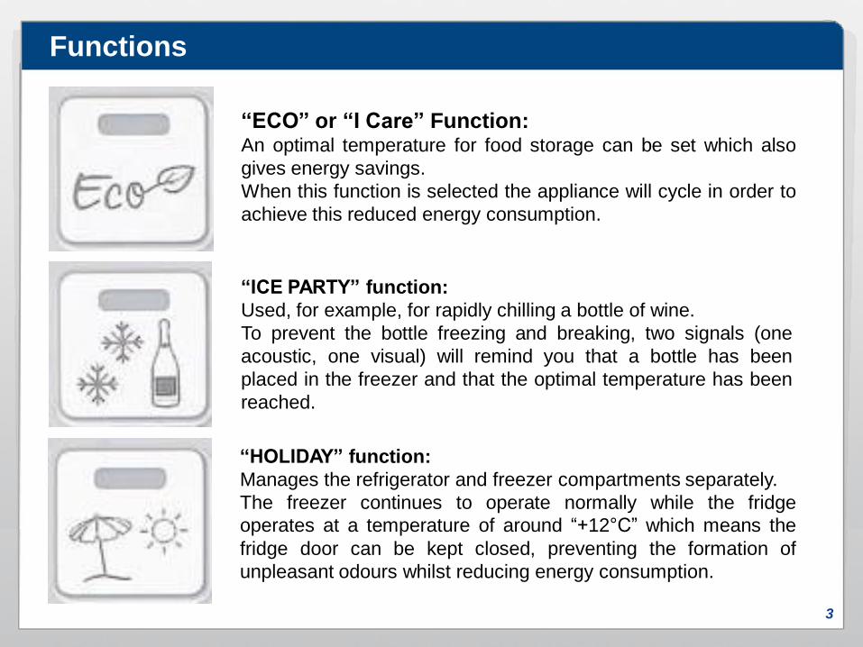
3
“ECO” or “I Care” Function:An optimal temperature for food storage can be set which also
gives energy savings.
When this function is selected the appliance will cycle in order to
achieve this reduced energy consumption.
“ICE PARTY” function:
Used, for example, for rapidly chilling a bottle of wine.
To prevent the bottle freezing and breaking, two signals (one
acoustic, one visual) will remind you that a bottle has been
placed in the freezer and that the optimal temperature has been
reached.
Functions
“HOLIDAY” function:
Manages the refrigerator and freezer compartments separately.
The freezer continues to operate normally while the fridge
operates at a temperature of around “+12°C” which means the
fridge door can be kept closed, preventing the formation of
unpleasant odours whilst reducing energy consumption.
4
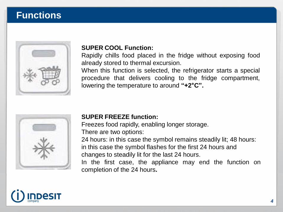
SUPER COOL Function:
Rapidly chills food placed in the fridge without exposing food
already stored to thermal excursion.
When this function is selected, the refrigerator starts a special
procedure that delivers cooling to the fridge compartment,
lowering the temperature to around “+2°C”.
SUPER FREEZE function:
Freezes food rapidly, enabling longer storage.
There are two options:
24 hours: in this case the symbol remains steadily lit; 48 hours:
in this case the symbol flashes for the first 24 hours and
changes to steadily lit for the last 24 hours.
In the first case, the appliance may end the function on
completion of the 24 hours.
Functions

5
Functioning logic
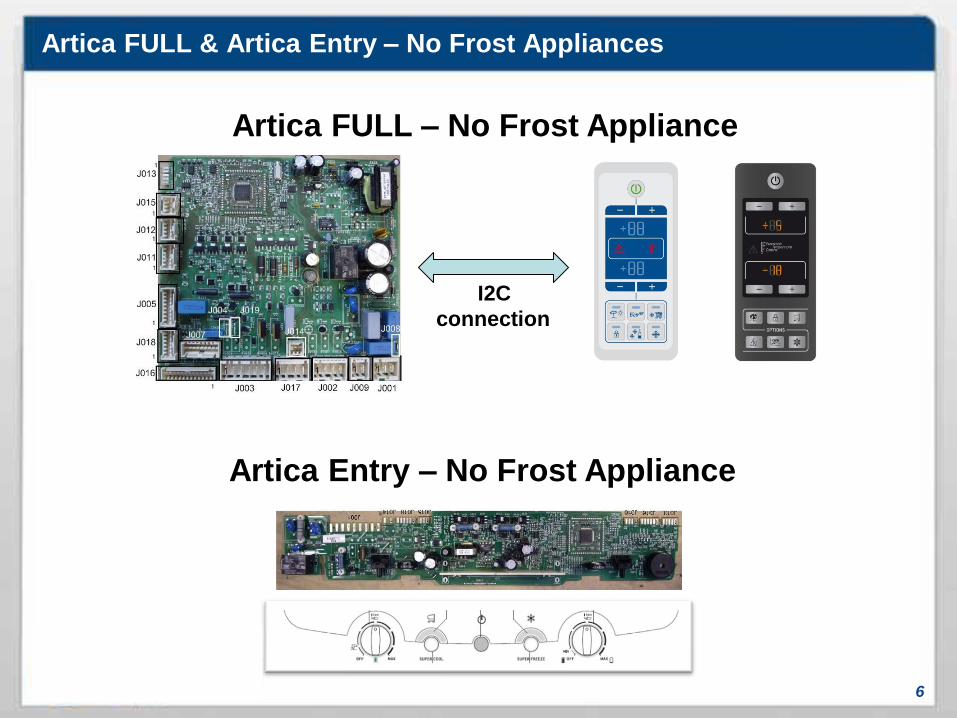
Artica FULL & Artica Entry – No Frost Appliances
6
Artica FULL – No Frost Appliance
I2C
connection
Artica Entry – No Frost Appliance

Artica FULL & Artica Entry - “Normal” Functioning
7
Description• This function is active when no other function is activated from the
user interface.
• The fridge air probe determines when to start and stop chilling the
fridge compartment, based on the temperature setting made by the
user with the user interface.
When the fridge compartment needs to be cooled, the compressor
is activated, the fan switched on and the damper opened.
• The freezer air probe determines when to start and stop chilling the
freezer compartment, based on the temperature setting made with
the control panel.
When the freezer compartment needs to be cooled, the
compressor is activated and the fan switched on. The damper
remains closed.
• When the fridge door is opened during a cooling demand from the
fridge compartment, the damper is closed and the freezer fan is
switched off if there is no cooling demand from the freezer. When
the fridge door is closed, the damper is re-opened and the fan is
switched back on again.
• In the event of a black-out, when the power supply is restored,
normal appliance functioning is also restored.
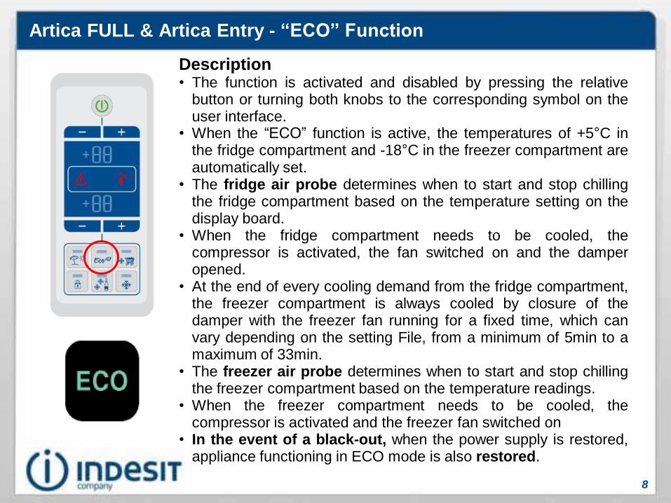
Artica FULL & Artica Entry - “ECO” Function
8
Description• The function is activated and disabled by pressing the relative
button or turning both knobs to the corresponding symbol on theuser interface.
• When the “ECO” function is active, the temperatures of +5°C inthe fridge compartment and -18°C in the freezer compartment areautomatically set.
• The fridge air probe determines when to start and stop chillingthe fridge compartment based on the temperature setting on thedisplay board.
• When the fridge compartment needs to be cooled, thecompressor is activated, the fan switched on and the damperopened.
• At the end of every cooling demand from the fridge compartment,the freezer compartment is always cooled by closure of thedamper with the freezer fan running for a fixed time, which canvary depending on the setting File, from a minimum of 5min to amaximum of 33min.
• The freezer air probe determines when to start and stop chillingthe freezer compartment based on the temperature readings.
• When the freezer compartment needs to be cooled, thecompressor is activated and the freezer fan switched on
• In the event of a black-out, when the power supply is restored,appliance functioning in ECO mode is also restored.

Artica FULL & Artica Entry - “Holiday” function
9
Description• The function is activated and disabled by pressing the
button on the user interface or turning the knob to the
corresponding symbol.
• The fridge air probe determines when to start and stop
chilling the fridge compartment at warmer temperatures
than for normal function (+12°C).
• The freezer air probe determines when to start and stop
chilling the freezer compartment with the temperature
threshold set at -18°C.
• In the event of a black-out, when the power supply is
restored, this function is also restored.
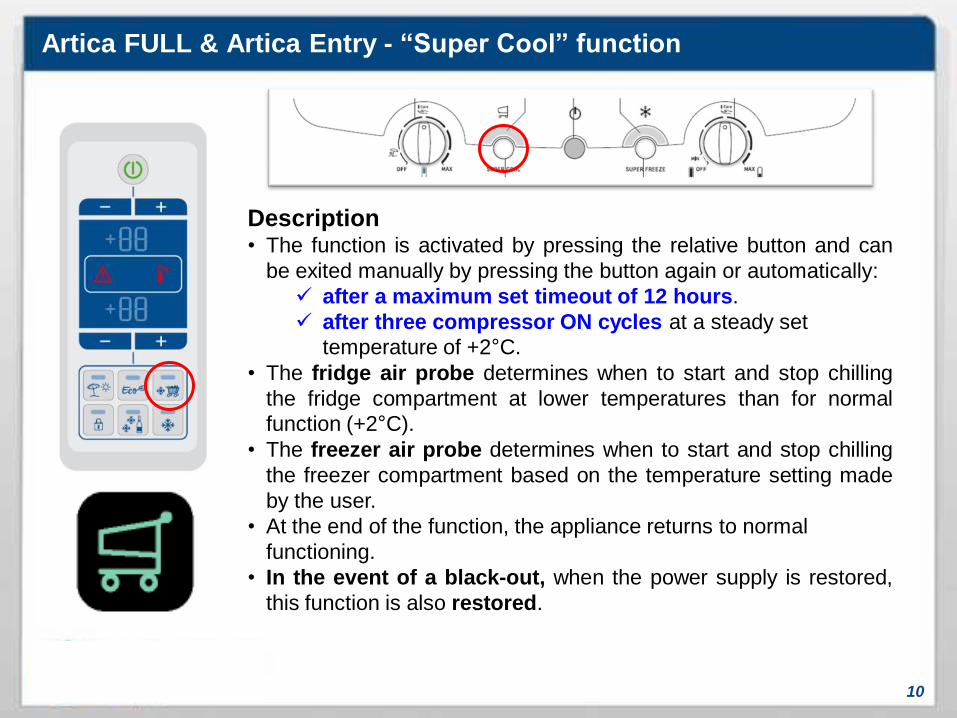
Artica FULL & Artica Entry - “Super Cool” function
10
Description• The function is activated by pressing the relative button and can
be exited manually by pressing the button again or automatically:
after a maximum set timeout of 12 hours.
after three compressor ON cycles at a steady set
temperature of +2°C.
• The fridge air probe determines when to start and stop chilling
the fridge compartment at lower temperatures than for normal
function (+2°C).
• The freezer air probe determines when to start and stop chilling
the freezer compartment based on the temperature setting made
by the user.
• At the end of the function, the appliance returns to normal
functioning.
• In the event of a black-out, when the power supply is restored,
this function is also restored.

Artica FULL & Artica Entry - “Super Freeze 24h” function
11
Description• The function is activated by pressing the relative button on the control
panel and can be disabled: manually by pressing the button again or
automatically after 24 hours max.
• When the function is activated, the appliance runs a defrost cycle
if and only if the appliance has accumulated at least 3 hours of
compressor ON since the last defrost cycle performed.
• The fridge air probe determines when to start and stop chilling the
fridge compartment, based on the temperature setting made by the
user.
• The freezer compartment is cooled continuously for 24 hours
• In the event of a black-out, when the power supply is restored, th
Super Freeze function is also restored.
Important:
Super Freeze 48 hours is not available. The appliance will complete
the function automatically based on time and NEVER due to
reaching a set temperature as was the case with previous platforms.

Artica FULL & Artica Entry - “Ice Party” function
12
Description• The function is activated by pressing the relative button
on the user interface and can be disabled manually by
pressing the button again or automatically after 30
minutes.
• The fridge air probe determines when to start and stop
chilling the fridge compartment, based on the
temperature setting made using the control panel.
• The freezer compartment chills continuously (compressor
ON) for 30 minutes, activating the compressor and the
freezer fan. After this time, an acoustic signal sounds to
remind the user to remove the bottle.
• In the event of a black-out, when the power supply is
restored, the alarm is activated, prompting removal of the
bottle.

Artica FULL & Artica Entry - “A1” alarm
13
Description• The “A1” alarm is only displayed if there is no Pre-Fault or Fault.
• The alarm is activated when the temperature measured by the freezer air probe is such
that food might be damaged. In this case, it is advisable to use food immediately or cook
it and then refreeze it.
• When an alarm condition occurs, it is indicated on the user interface with the message
“A1” or the simultaneous flashing of the “Super Cool” & “Super Freeze” LEDs, in
addition to an acoustic signal.
The buzzer can be muted by opening and closing the refrigerator door.
• The alarm can be reset by switching the appliance off using the control panel.
• Fridge compartment function remains the same as during normal functioning.
• The freezer compartment functions at temperatures that will not refreeze the food stored
inside (0°C).
• Defrost cycles are forced every 2 hours.
NB: The thresholds are the same as the Cooling 2005/2008 platform.
Always avoid unplugging the appliance: switch off using the U.I.
T1 = 2 1/2 Hours
T2 = 24 Hours
T3 = 120 Hours
A2 threshold
A1 threshold
Check threshold
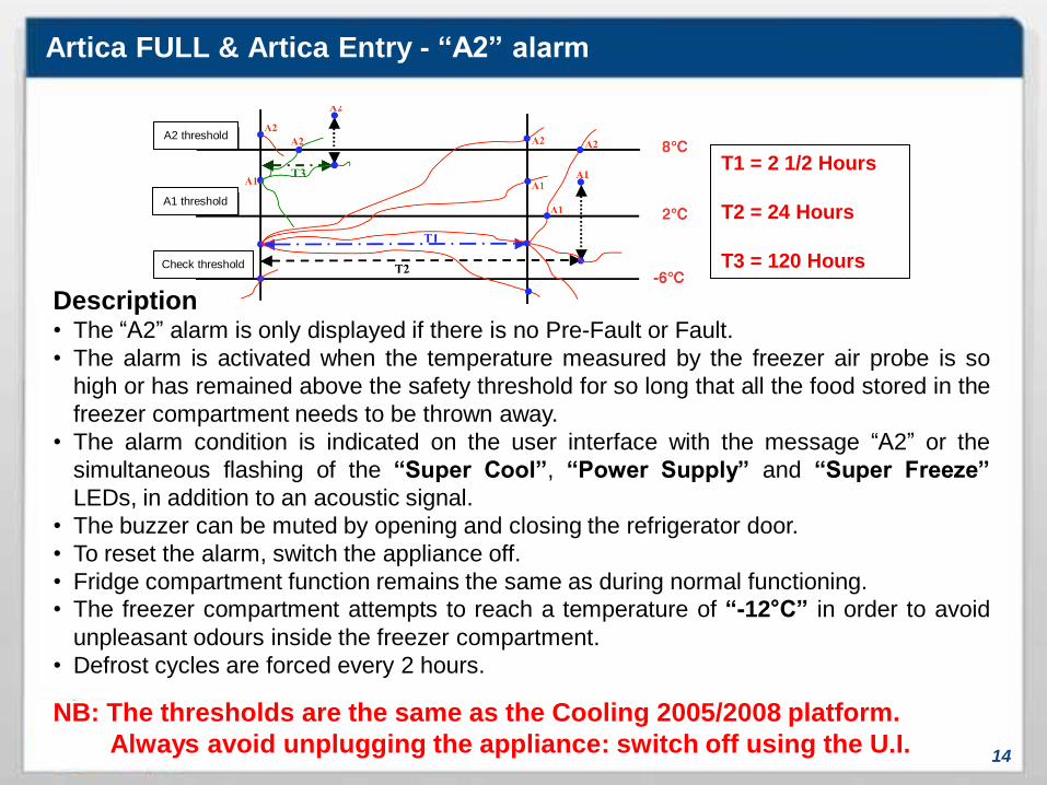
Artica FULL & Artica Entry - “A2” alarm
14
Description• The “A2” alarm is only displayed if there is no Pre-Fault or Fault.
• The alarm is activated when the temperature measured by the freezer air probe is so
high or has remained above the safety threshold for so long that all the food stored in the
freezer compartment needs to be thrown away.
• The alarm condition is indicated on the user interface with the message “A2” or the
simultaneous flashing of the “Super Cool”, “Power Supply” and “Super Freeze”
LEDs, in addition to an acoustic signal.
• The buzzer can be muted by opening and closing the refrigerator door.
• To reset the alarm, switch the appliance off.
• Fridge compartment function remains the same as during normal functioning.
• The freezer compartment attempts to reach a temperature of “12°C” in order to avoid
unpleasant odours inside the freezer compartment.
• Defrost cycles are forced every 2 hours.
NB: The thresholds are the same as the Cooling 2005/2008 platform.
Always avoid unplugging the appliance: switch off using the U.I.
T1 = 2 1/2 Hours
T2 = 24 Hours
T3 = 120 Hours
A2 threshold
A1 threshold
Check threshold
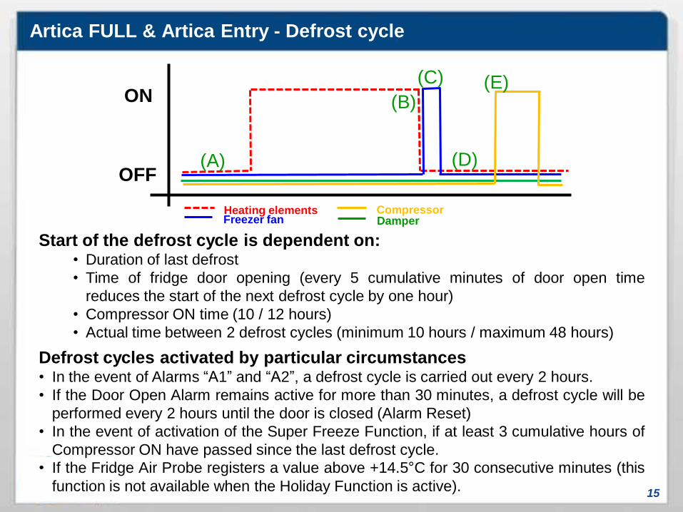
Artica FULL & Artica Entry - Defrost cycle
15
Start of the defrost cycle is dependent on:• Duration of last defrost
• Time of fridge door opening (every 5 cumulative minutes of door open time
reduces the start of the next defrost cycle by one hour)
• Compressor ON time (10 / 12 hours)
• Actual time between 2 defrost cycles (minimum 10 hours / maximum 48 hours)
Defrost cycles activated by particular circumstances• In the event of Alarms “A1” and “A2”, a defrost cycle is carried out every 2 hours.
• If the Door Open Alarm remains active for more than 30 minutes, a defrost cycle will be
performed every 2 hours until the door is closed (Alarm Reset)
• In the event of activation of the Super Freeze Function, if at least 3 cumulative hours of
Compressor ON have passed since the last defrost cycle.
• If the Fridge Air Probe registers a value above +14.5°C for 30 consecutive minutes (this
function is not available when the Holiday Function is active).
ON
OFF(A)
(B)
(C) (E)
(D)
Heating elementsFreezer fan Damper
Compressor
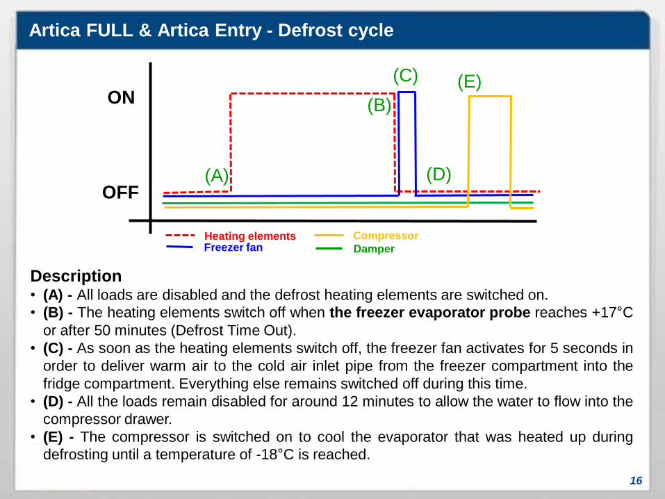
Artica FULL & Artica Entry - Defrost cycle
16
Description• (A) - All loads are disabled and the defrost heating elements are switched on.
• (B) - The heating elements switch off when the freezer evaporator probe reaches +17°C
or after 50 minutes (Defrost Time Out).
• (C) - As soon as the heating elements switch off, the freezer fan activates for 5 seconds in
order to deliver warm air to the cold air inlet pipe from the freezer compartment into the
fridge compartment. Everything else remains switched off during this time.
• (D) - All the loads remain disabled for around 12 minutes to allow the water to flow into the
compressor drawer.
• (E) - The compressor is switched on to cool the evaporator that was heated up during
defrosting until a temperature of -18°C is reached.
ON
OFF(A)
(B)
(C) (E)
(D)
Heating elementsFreezer fan Damper
Compressor
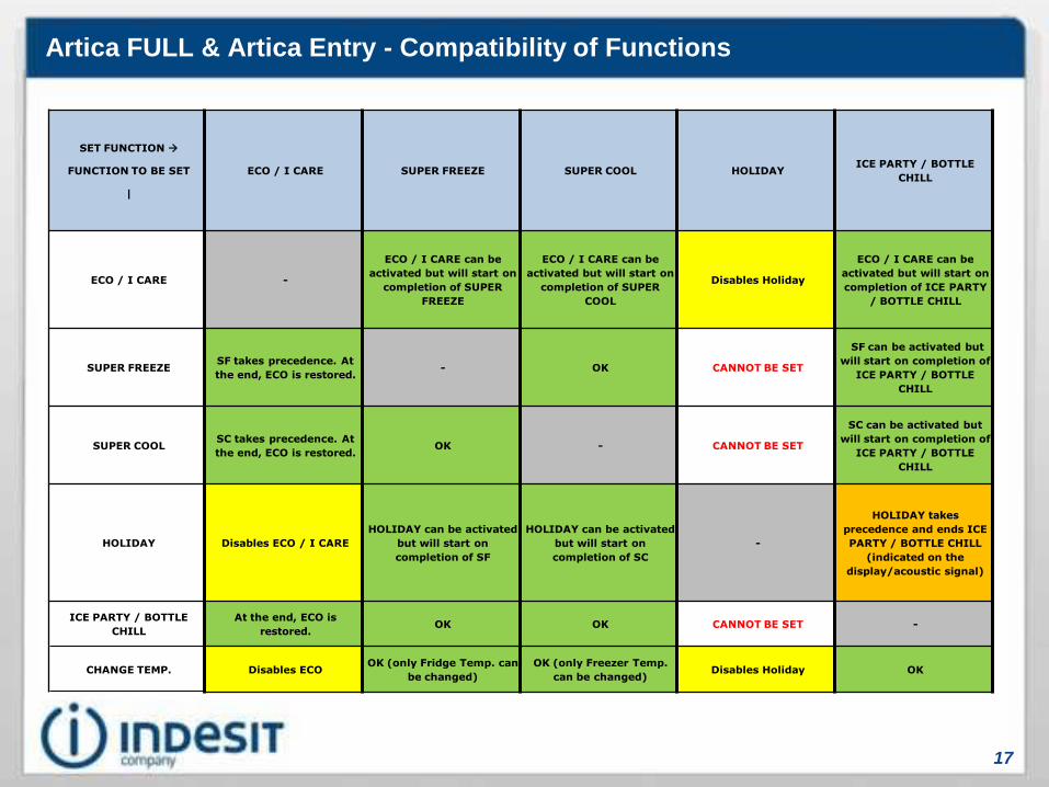
Artica FULL & Artica Entry - Compatibility of Functions
17
SET FUNCTION
FUNCTION TO BE SET
|
ECO / I CARE SUPER FREEZE SUPER COOL HOLIDAYICE PARTY / BOTTLE
CHILL
ECO / I CARE -
ECO / I CARE can be
activated but will start on
completion of SUPER
FREEZE
ECO / I CARE can be
activated but will start on
completion of SUPER
COOL
Disables Holiday
ECO / I CARE can be
activated but will start on
completion of ICE PARTY
/ BOTTLE CHILL
SUPER FREEZESF takes precedence. At
the end, ECO is restored.- OK CANNOT BE SET
SF can be activated but
will start on completion of
ICE PARTY / BOTTLE
CHILL
SUPER COOLSC takes precedence. At
the end, ECO is restored.OK - CANNOT BE SET
SC can be activated but
will start on completion of
ICE PARTY / BOTTLE
CHILL
HOLIDAY Disables ECO / I CARE
HOLIDAY can be activated
but will start on
completion of SF
HOLIDAY can be activated
but will start on
completion of SC
-
HOLIDAY takes
precedence and ends ICE
PARTY / BOTTLE CHILL
(indicated on the
display/acoustic signal)
ICE PARTY / BOTTLE
CHILL
At the end, ECO is
restored.OK OK CANNOT BE SET -
CHANGE TEMP. Disables ECOOK (only Fridge Temp. can
be changed)
OK (only Freezer Temp.
can be changed)Disables Holiday OK

THR3
18
THR3 NF – No Frost Appliance(Electronic thermostat)

THR3 – “Normal” Functioning
19
Description• The fridge damper is mechanical.
• The freezer air probe determines when the compressor comes on and off in order to
stop chilling the freezer compartment depending on the setting of the knob on the
control panel.
Fridge door:• Management of fridge door alarm when it is left open for more than 2 minutes
• The alarm is signalled visually by the flashing fridge light.
• The alarm is reset when the door is closed.
• Once the door has been open for 30 minutes, a defrost cycle is activated every 2
hours.

THR3 - Defrost cycle
20
Start of the defrost cycle depends on:• Duration of last defrost
• Time of fridge door opening (every 5 cumulative minutes reduces the start of
the next defrost cycle by one hour)
• Total compressor ON time since last defrost (10 / 12 hours)
• Actual time between 2 defrost cycles (minimum 10 hours – maximum 48
hours)
On
Off
(A)
(B)
(E)
(D)
(F)
Heating elementsFreezer fan
Compressor
(G)(C)

THR3 - Defrost cycle
21
Defrost Cycle:• (A) - Start of defrost, the fan runs for 4 minutes
• (B) - All the loads are disabled
• (C) - The defrost heating element switches on.
• (D) - The heating element switches off when the freezer evaporator probe
reaches the preset value of 17°C or the maximum set time of 70 minutes has
elapsed.
• (E) - When the heating element switches off the fan runs for 20 seconds.
• (F) - All the loads remain disabled for around 10 minutes to allow the water to flow
into the compressor drawer.
• (G) - The compressor is switched on to cool the coil that has heated up during
defrosting until a temperature of -18°C is reached.
On
Off
(A)
(B)
(E)
(D)
(F)
Heating elementsFreezer fan
Compressor
(G)(C)

22
Components

23
Components
Temperature Probes:The “NTC” Temperature Probes have
the same settings used in the Cooling platform
2005/2008. There are 3:
1. Refrigerator air probe: Which measures
the temperature inside the refrigerator
compartment and relays to the main board
any cooling demand and/or the fact that the
thermostat temperature has been reached.
2. Freezer air probe: Which measures the
temperature inside the freezer compartment
and relays to the main board any cooling
demand and/or the fact that the thermostat
temperature has been reached.
3. Evaporator probe: manages the end of the
defrost cycle by detecting when the set
temperature of +17°C is reached.
IMPORTANT:
The ohm values for checking that the probes are in good working order are the same
used until now since the probes remain unchanged.
1
3
2

24
Temperature Probes:As in Platform 2005/2008, in the event of
malfunction (short circuit or open circuit) of one
or more probes, the appliance will start cycling,
using internal compressor ON/OFF tables
based on the choices made by the user with the
user interface.
IMPORTANT:
The ohm values for checking that the probes are in good working order are the same
used until now since the probes remain unchanged.
Temperatures
(degrees C)
Impedance
(Ohms)
Components

25
Heating elements:Defrosting is performed by the defrost heating
elements. One element covers both sides of the
freezer evaporator with an extension designed to
avoid use of the foam-protected drip tray heating
element used on the previous platform, and a
second element surrounds the foam-protected
air return pipeline.
The evaporator heating element used in three-
drawer appliances and that used in four-drawer
appliances differ in length, nonetheless they
have the same reference value for checking
correct operation (see table below).
Electrical characteristics:• Operating voltage.: 220 - 240 Volts
• Impedance……….: approx. 302.5 Ohm
• At 220 Volts, it has a power rating of: approx. 160 Watts
• At 240 Volts, it has a power rating of: approx. 190 Watts
Components
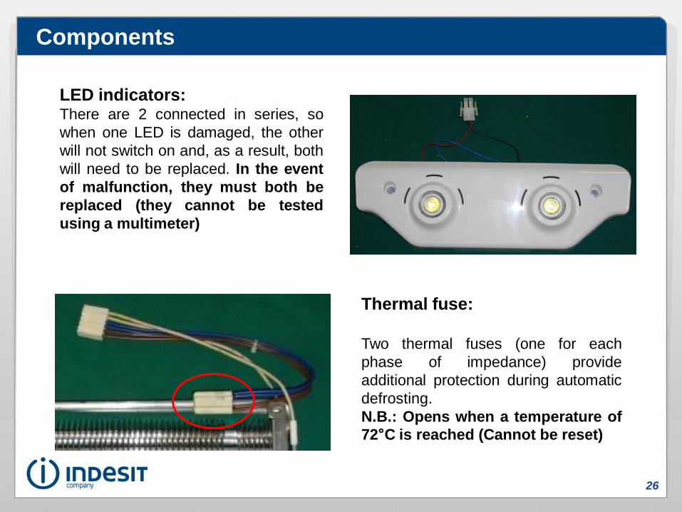
26
LED indicators:There are 2 connected in series, so
when one LED is damaged, the other
will not switch on and, as a result, both
will need to be replaced. In the event
of malfunction, they must both be
replaced (they cannot be tested
using a multimeter)
Thermal fuse:
Two thermal fuses (one for each
phase of impedance) provide
additional protection during automatic
defrosting.
N.B.: Opens when a temperature of
72°C is reached (Cannot be reset)
Components
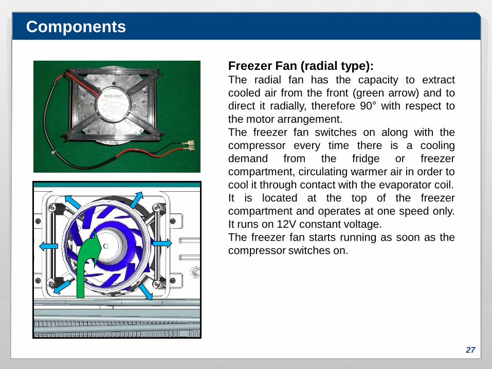
27
Freezer Fan (radial type):The radial fan has the capacity to extract
cooled air from the front (green arrow) and to
direct it radially, therefore 90° with respect to
the motor arrangement.
The freezer fan switches on along with the
compressor every time there is a cooling
demand from the fridge or freezer
compartment, circulating warmer air in order to
cool it through contact with the evaporator coil.
It is located at the top of the freezer
compartment and operates at one speed only.
It runs on 12V constant voltage.
The freezer fan starts running as soon as the
compressor switches on.
Components

28
Refrigerator Compartment Multiflow:The fridge multiflow ensures correct air distribution
throughout the fridge compartment by means of
variable diameter vent outlets.
Depending on the height of the fridge
compartment, there are various levels of
cooling:
• height 1750mm: - Electronic 3 levels
- Mechanical 2 levels
• height 1875mm: - Electronic 4 levels
- Mechanical 3 levels
• height 2000mm: - Electronic 5 levels
- Mechanical 4 levels
Cold air exiting
Warm air returning
Components

29
Freezer air outlet vents
Freezer air outlet vents
Freezer multiflow
Air return vents
Cold air exiting
Warm air returning
Freezer Compartment Multiflow:
The freezer multiflow also has the task
of distributing air, in this case
throughout the freezer compartment.
There are different versions of
freezer multiflows:
• 3-drawer electronic appliances:
2 open levels (4 open vents)
• 3-drawer mechanical appliances:
3 open levels (6 open vents)
• 4-drawer electronic and mechanical
appliances: 4 open levels (8 open
vents)
In all cases there are two vents at the
bottom for drawing in air and
channeling it to the evaporator coil.
Components

30
External Air Flow (Fridge Compartment Cooling):Cold air is forced by the radial fan through the smallest
channel (blue arrow) passing through the damper, and is
distributed through the fridge compartment by the multiflow.
Fridge inlet duct
Fridge return duct
Warm air is forced out of the fridge compartment through the longer channel to
the bottom of the freezer compartment, where it comes into contact with the
evaporator coil and is cooled once again.
Components

31
Fridge inlet duct
Fridge return duct
Evaporator coil
Freezer multiflow
Fan unit
Components
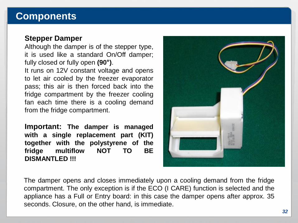
32
Stepper DamperAlthough the damper is of the stepper type,
it is used like a standard On/Off damper;
fully closed or fully open (90°).
It runs on 12V constant voltage and opens
to let air cooled by the freezer evaporator
pass; this air is then forced back into the
fridge compartment by the freezer cooling
fan each time there is a cooling demand
from the fridge compartment.
Important: The damper is managed
with a single replacement part (KIT)
together with the polystyrene of the
fridge multiflow NOT TO BE
DISMANTLED !!!
The damper opens and closes immediately upon a cooling demand from the fridge
compartment. The only exception is if the ECO (I CARE) function is selected and the
appliance has a Full or Entry board: in this case the damper opens after approx. 35
seconds. Closure, on the other hand, is immediate.
Components
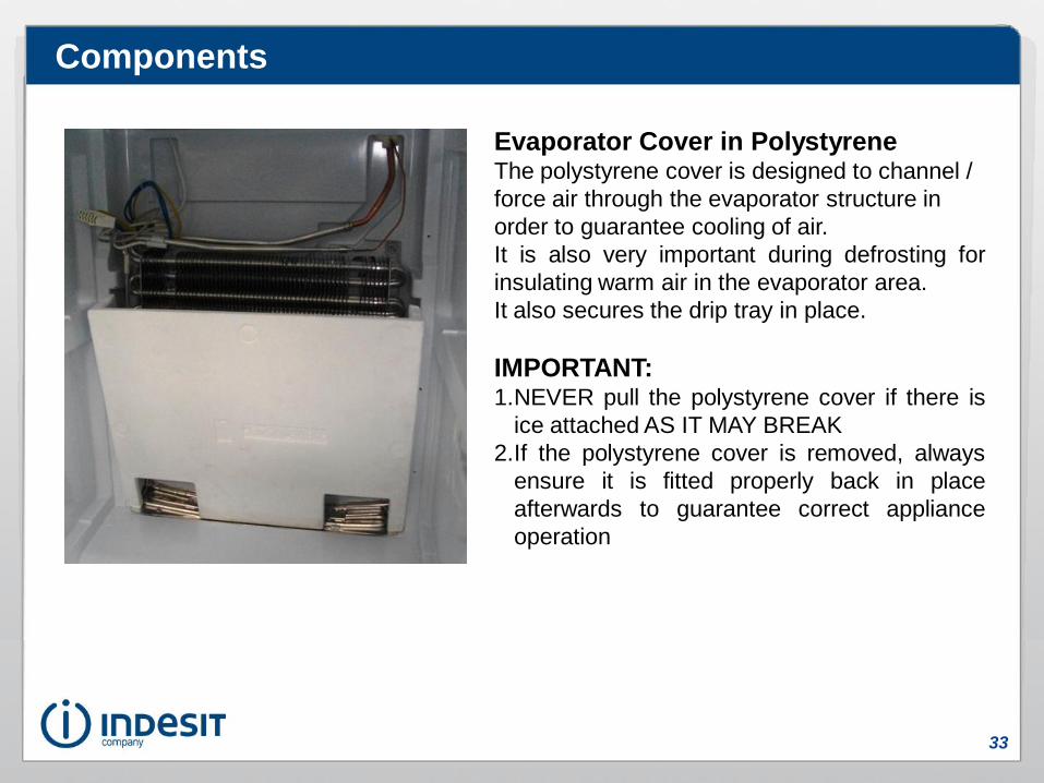
33
Evaporator Cover in PolystyreneThe polystyrene cover is designed to channel /
force air through the evaporator structure in
order to guarantee cooling of air.
It is also very important during defrosting for
insulating warm air in the evaporator area.
It also secures the drip tray in place.
IMPORTANT:1.NEVER pull the polystyrene cover if there is
ice attached AS IT MAY BREAK
2.If the polystyrene cover is removed, always
ensure it is fitted properly back in place
afterwards to guarantee correct appliance
operation
Components

34
Compressor:When the appliance is switched on for the first time, the compressor only starts after
8 minutes.
Between one start-up and the next one there is a minimum safety time of 8 minutes.
Situations in which the compressor remains off even in the presence
of a cooling demand:1. When the electronic protection device is in operation
2. When the electric protection device (Clixon) is activated
3. After the end of defrosting
4. After completion of the "Super Freeze" function
Components
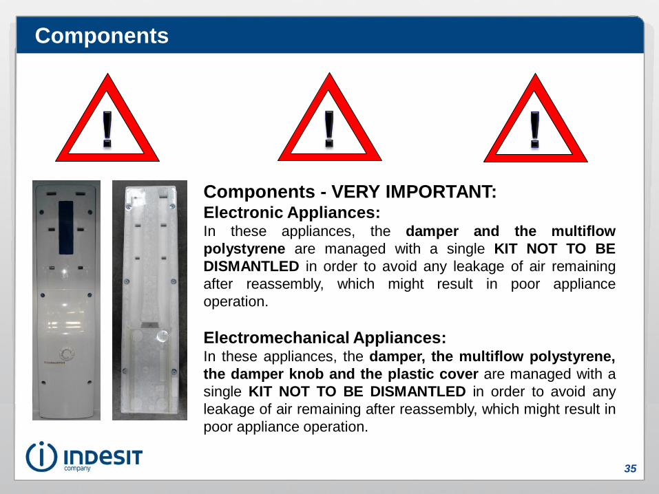
35
Components - VERY IMPORTANT:Electronic Appliances:In these appliances, the damper and the multiflow
polystyrene are managed with a single KIT NOT TO BE
DISMANTLED in order to avoid any leakage of air remaining
after reassembly, which might result in poor appliance
operation.
Electromechanical Appliances:In these appliances, the damper, the multiflow polystyrene,
the damper knob and the plastic cover are managed with a
single KIT NOT TO BE DISMANTLED in order to avoid any
leakage of air remaining after reassembly, which might result in
poor appliance operation.
Components

36
Wiring Diagrams
Entry Wiring Diagram(SQG_CL_310)
THR3 Wiring Diagram(SQG_CL_311)
FULL Wiring Diagram (SQG_CL_312)
Internal Connection
Wiring Diagram

37
Serviceability

Artica FULL – Demo Mode
38
Activating Demo Mode:Start with the appliance off.
To activate the function, press the buttons
“ECO/I CARE” and “HOLIDAY”
simultaneously for 6 seconds. “dE” and
“On” will appear on the display together with
an acoustic signal confirming activation.
Disabling Demo Mode:Switch the product off.
Press the buttons “ECO/I CARE” and
“HOLIDAY” simultaneously for 6 seconds.
“dE” and “OFF” will appear on the display.
N.B.: If the appliance is unplugged or
there is a black-out, the function is
automatically switched off.

Artica FULL - Autotest Procedure
39
Autotest Activation:The function can be activated only with the
appliance turned OFF by pressing the buttons
HOLIDAY, SUPER COOL and SUPER
FREEZE simultaneously for 6 seconds.
Autotest Deactivation:The appliance can exit the autotest procedure
in 3 different ways:
1.After 255 seconds (duration of procedure)
2.By switching on the appliance (using On/Off
button)
3.By unplugging the appliance from the mains
socket
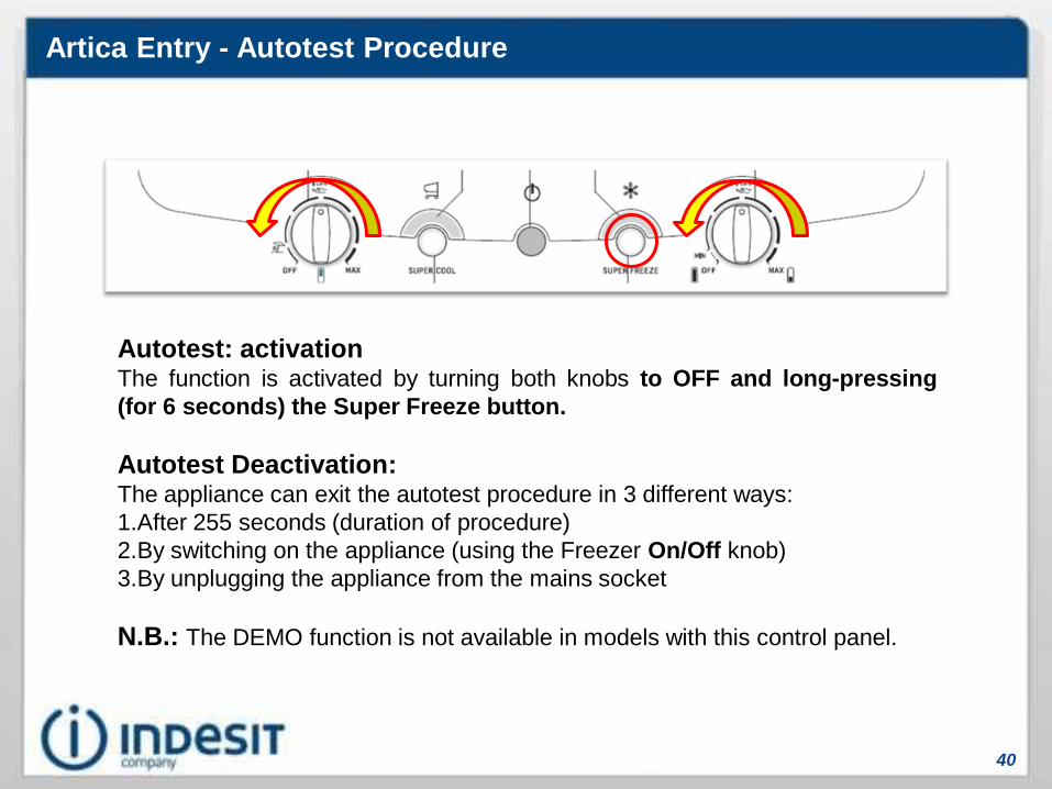
Artica Entry - Autotest Procedure
40
Autotest: activationThe function is activated by turning both knobs to OFF and long-pressing
(for 6 seconds) the Super Freeze button.
Autotest Deactivation:The appliance can exit the autotest procedure in 3 different ways:
1.After 255 seconds (duration of procedure)
2.By switching on the appliance (using the Freezer On/Off knob)
3.By unplugging the appliance from the mains socket
N.B.: The DEMO function is not available in models with this control panel.

Artica FULL & Artica Entry - Autotest Procedure
41
Step Duration Action Light Notes1 5 seconds Pause OFF
2 1 second Probe check OFFIf the probes have not failed, skip to step 3.
If the probes have failed, skip to step 6
3 4 seconds Pause OFF
4 125 secondsFZ fan ON
Heating element ON (*)Damper open
OFF
5 120 secondsFZ fan ON
Heating element ON (*)Damper closed
OFF Skip to step 8
6 125 secondsFZ fan ON
Heating element ON (*)Damper open
Flashing
7 120 secondsFZ fan ON
Heating element ON (*)Damper closed
Flashing
8 Autotest closes
Autotest procedure (Full and Entry board)
(*) Important: Bear in mind that the heating elements are connected in parallel so, in
the event only one of them is interrupted, this Fault will not be detected and the Autotest
procedure will finish without signalling any problems.com
Any Last Fault or Non Critical Fault will be shown on the display for the first 20 seconds
after Autotest activation, after which the cycle starts as follows:
Artica FULL & Artica Entry – Critical and Non-critical Faults
42
Critical Faults:These are faults which prevent the appliance from functioning because they
involve a major functional component, for example: Main board, setting file,
solenoid valve.
They are automatically displayed by the appliance:
Critical faults are displayed ONLY IF THE MAIN BOARD DETECTS A
SIMULTANEOUS TEMPERATURE ALARM (“A1” OR “A2”)
Non-critical Faults:These are faults which, even when present, do not compromise the normal
functioning of the appliance, for example: Fridge fan, multiflow heating element.
THEY ARE NOT AUTOMATICALLY DISPLAYED BY THE APPLIANCE since they
do not pose any hazard or risk compromising appliance operation.
They are displayed for 20 seconds when the autotest procedure is activated.

Artica FULL & Artica Entry – Fault & Last Fault Management
43
Fault :• If CRITICAL, it is automatically displayed and the buzzer sounds. To mute the
buzzer, simply open and shut the fridge door. To RESET THE FAULT, switch the
appliance off at the control panel or unplug it from the mains power supply.
• If NON-CRITICAL, it is displayed only for the first 20 seconds when the Autotest
procedure is started. It is only wiped from the memory once the problem has
been solved and the Autotest procedure re-started and completed.
Last Fault:Displayed for the first 20 seconds when the Autotest procedure is started.
To wipe Last Fault from memory, simply complete the current autotest procedure.

Artica FULL & Artica Entry – Fault & Last Fault Management
44
Important notes.
• Critical Faults are displayed only if an alarm condition is also present at the
same time (“A1” or “A2”).
• In a Pre-Fault condition, functions selected using the user interface are not
activated and the alarms “A1” and “A2” are not displayed until the Fault is
confirmed or rejected.
• Faults take precedence over Alarms “A1” and “A2”
• The “A1” or “A2” alarm is displayed only in the absence of a Pre-Fault or Fault.
• During display of a Critical Fault, all function previously chosen by the user are
cancelled and the freezer compartment starts cycling in an attempt to function at
0°C or -12°C, depending on the alarm condition present along with the Fault.

THR3 - Autotest cycle
45
Autotest Activation:The function is activated by turning the knob on the control panel very quickly from
OFF to maximum then back to OFF
Autotest Deactivation:The appliance can exit the autotest procedure in 3 different ways:
1.After 255 seconds (duration of procedure)
2.By switching on the appliance (using On/Off button)
3.By unplugging the appliance from the mains socket
NB: The DEMO function is not available in models with this control panel.

THR3 - Autotest procedure
46
Autotest sequence for THR3
For 10 seconds, activation of FZ fan, defrost heating element and fridge light.
All loads off for 3 seconds.
Probe check
If one of the two probes has a fault, the fridge light flashes for 5 seconds.
(1 second ON and 1 second OFF)
If everything is OK and there are no probe faults, the fridge light remains ON for 5 seconds.
All loads off for 3 seconds.
Defrost heating element check
If there is a defrost heating element fault, the fridge light flashes for 5 seconds (1 second ON and 1 seconds
OFF).
If everything is OK and there is no probe heating element fault, the fridge light remains ON for 5 seconds.
All loads off for 3 seconds.
Electronic board check
If there is an electronic board fault, the fridge light flashes for 5 seconds (1 second ON and 1 seconds OFF).
If everything is OK and there is no electronic board fault, the fridge light remains ON for 5 seconds.
All loads off for 3 seconds.
Pause for 7 seconds.
FZ air probe check
If there is a fault relating to the FZ air probe, the fridge light flashes for 5 seconds.
(1 second ON and 1 second OFF)
If everything is OK and there is no FZ air probe fault, the fridge light remains ON for 5 seconds.
All loads off for 3 seconds.
FZ evaporator probe check
If there is a fault relating to the FZ evaporator, the fridge light flashes for 5 seconds.
(1 second ON and 1 second OFF)
If everything is OK and there is no FZ evaporator fault, the fridge light remains ON for 5 seconds.
All loads off for 3 seconds.
Activation of FZ fan and defrost heating element for 217 seconds.

47
Demo Mode / Autotest / Autotest Sequence / Fault Table
MID Indesit Interface(SQG_CL_29)
MID H/A Interface(SQG_CL_30)
Entry Interface(SQG_CL_28)
Artica Fault Table(SQG_CL_31)
THR3 Interface(SQG_CL_32)

48
Serviceability
For main board programming in the
ARTICA platform, follow one of the
three methods:
1. Using the handheld/FFA (with
MemWriter)
2. Using a PC (in UK)
3. Using a Smart Reader plus the
Smart Card for the rest of the
world (described in SQG_WM_25)
Whichever method is used, refer to
documentation on the relative
technology
Upgrading
Low-End Adapter(TB001328)
49
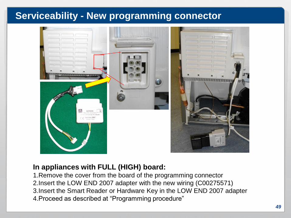
Serviceability - New programming connector
In appliances with FULL (HIGH) board:1.Remove the cover from the board of the programming connector
2.Insert the LOW END 2007 adapter with the new wiring (C00275571)
3.Insert the Smart Reader or Hardware Key in the LOW END 2007 adapter
4.Proceed as described at “Programming procedure”

50
In appliances with Entry board:1.Connect the LOW END 2007 adapter (with the new C00275571 wiring) to the
connector located in the compressor area
2.Insert the Smart Reader or Hardware Key in the modified LOW END 2007 adapter
3.Proceed as described at “Programming procedure”
N.B.: THR3 boards are not programmable.
Serviceability - New programming connector

51
Disassembly
52
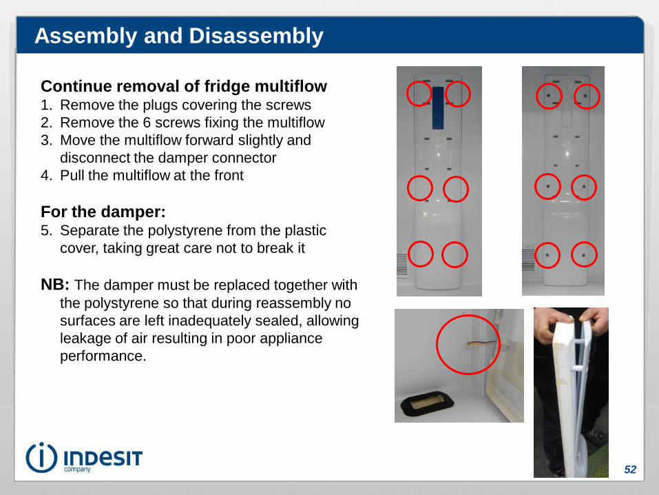
Assembly and Disassembly
Continue removal of fridge multiflow1. Remove the plugs covering the screws
2. Remove the 6 screws fixing the multiflow
3. Move the multiflow forward slightly and
disconnect the damper connector
4. Pull the multiflow at the front
For the damper:5. Separate the polystyrene from the plastic
cover, taking great care not to break it
NB: The damper must be replaced together with
the polystyrene so that during reassembly no
surfaces are left inadequately sealed, allowing
leakage of air resulting in poor appliance
performance.

53
Disassembly of fridge air
return vent:1.Insert a flat blade screwdriver
in the top aperture of the vent
2.Pull the vent towards you
Disassembly of NTC probe housing:To remove the NTC probe housing, exert pressure at the side and dislodge it
from its seat by pulling it towards you. If this proves unsuccessful, insert a flat
blade screwdriver and prise open the catches to release the housing from its
seat (take care not to scratch the appliance internally or break the housing).
Assembly and Disassembly

54
Disassembly of freezer multiflow1.Remove the freezer compartment drawers
2.Unscrew the 6 fixing screws on the multiflow (some
models feature 8 screws, the additional 2 identified in
the photo with yellow circles)
3.Pull the multiflow gently at the bottom to remove it
4.Open the connectors cover by pressing the fixing
clips
5.Release the 2-wire connector from its seat (which
is that of the freezer fan)
TAKE CARE to disconnect the fan connector
before removing it completely.
2
3
4 5
Assembly and Disassembly
55
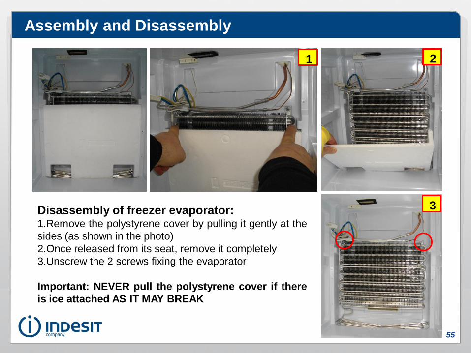
Disassembly of freezer evaporator:1.Remove the polystyrene cover by pulling it gently at the
sides (as shown in the photo)
2.Once released from its seat, remove it completely
3.Unscrew the 2 screws fixing the evaporator
Important: NEVER pull the polystyrene cover if there
is ice attached AS IT MAY BREAK
1 2
3
Assembly and Disassembly

56
Disassembly of freezer fan:1.Disassemble the freezer multiflow
2.Using a screwdriver, remove the 5 screws
fixing the freezer fan surround
3.Remove the surround (the fan is fixed to the
surround)
4.Using a screwdriver, remove the 4 screws
fixing the freezer fan to the surround
5.Remove the freezer fan
2
3 4 5
Assembly and Disassembly