essentials of visual modeling with uml module 2...
TRANSCRIPT

1
IBM Software Group
®
Essentials of Visual Modeling with UML
Module 2: Principles of Visual Modeling
2
Objectives
Describe the importance of visual modeling.Define the four principles of visual modeling.Explain what the Unified Modeling Language (UML) represents.Define the type of process that best relates to the UML.
3
Where Are We?
What is modeling?Four principles of visual modelingThe UMLProcess and visual modeling

4
What Is a Model?
A model is a simplification of reality.
5
Why Model?
Modeling achieves four aims:Helps you to visualize a system as you want it to be.Permits you to specify the structure or behavior of a system.Gives you a template that guides you in constructing a system.Documents the decisions you have made.
You build models of complex systems because you cannot comprehend such a system in its entirety.You build models to better understand the system you are developing.

6
The Importance of Modeling
Paper Airplane Fighter Jet
Less Important More Important

7
Software Teams Often Do Not Model
Many software teams build applications approaching the problem like they were building paper airplanes
Start coding from project requirementsWork longer hours and create more codeLacks any planned architectureDoomed to failure
Modeling is a common thread to successful projects

8
What is modeling?Four principles of visual modelingThe UMLProcess and visual modeling
Where Are We?

9
Four Principles of Modeling
The model you create influences how the problem is attacked.Every model may be expressed at different levels of precision.The best models are connected to reality.No single model is sufficient.

10
Principle 1: The Choice of Model Is Important
The models you create profoundly influence how a problem is attacked and how a solution is shaped.
In software, the models you choose greatly affect your world view.Each world view leads to a different kind of system.
Deployment DiagramProcess Model Design Model

11
Principle 2: Levels of Precision May Differ
Every model may be expressed at different levels of precision.
The best kinds of models let you choose your degree of detail, depending on:• Who is viewing the model. • Why they need to view it.
View for Designers View for Customers

12
Principle 3: The Best Models Are Connected to Reality
All models simplify reality.A good model reflects potentially fatal characteristics.

13
Principle 4: No Single Model Is Sufficient
No single model is sufficient. Every non-trivial system is best approached through a small set of nearly independent models.
Create models that can be built and studied separately, but are still interrelated.
Process View Deployment View
Logical View
Use-Case View
Implementation View
End-userFunctionality
ProgrammersSoftware management
Performancescalabilitythroughput
System integratorsSystem topology
delivery, installationcommunication
System engineering
Analysts/DesignersStructure

14
What is modeling?Four principles of visual modelingThe UMLProcess and visual modeling
Where Are We?
15
What Is the UML?
The UML is a language for• Visualizing• Specifying• Constructing• Documenting
the artifacts of a software-intensive system.

16
The UML Is a Language for Visualizing
Communicating conceptual models to others is prone to error unless everyone involved speaks the same language.There are things about a software system you can’t understand unless you build models.An explicit model facilitates communication.

17
The UML Is a Language for Specifying
The UML builds models that are precise, unambiguous, and complete.

18
The UML Is a Language for Constructing
UML models can be directly connected to a variety of programming languages.
Maps to Java, C++, Visual Basic, and so onTables in a RDBMS or persistent store in an OODBMSPermits forward engineeringPermits reverse engineering
19
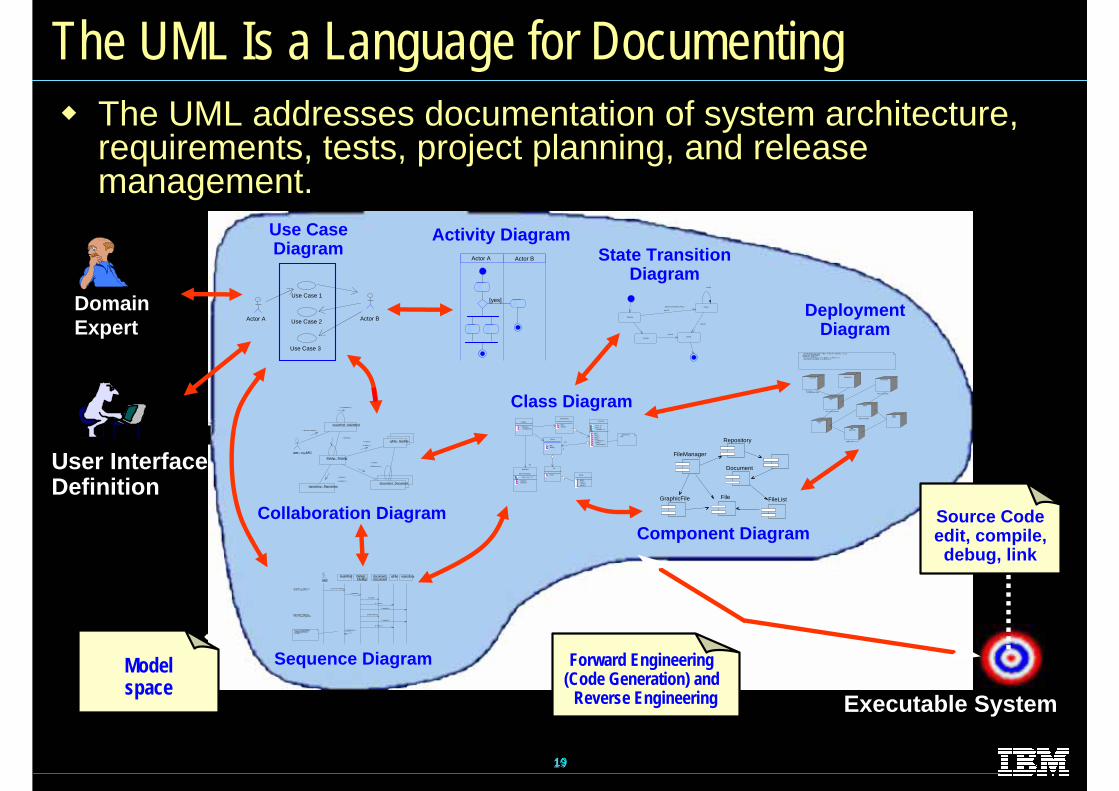
The UML Is a Language for Documenting
DomainExpert
User InterfaceDefinition
Use CaseDiagram
Actor A
Use Case 1
Use Case 2
Use Case 3
Actor B
Activity Diagram
[yes]
Actor A Actor B
Class Diagram
GrpFile
read( )open( )create( )fillFile( )
rep
Repository
name : char * = 0
readDoc( )readFile( )
(from Persistence)
FileMgr
fetchDoc( )sortByName( )
DocumentList
add( )delete( )
Document
name : intdocid : int
numField : int
get( )open( )close( )read( )
sortFileList( )create( )
fillDocument( )fList
1
FileList
add( )delete( )
1
File
read( )
read() fill the code..
State TransitionDiagram
Openning
Writing
ReadingClosing
add file [ numberOffile==MAX ] /
flag OFF
add file
close file
close file
Component Diagram
Document
Repository
FileList
FileManager
GraphicFile File
Collaboration Diagram
user : »ç¿ëÀÚ
mainWnd : MainWnd
fileMgr : FileMgr
repository : Repositorydocument : Document
gFile : GrpFile
9: sortByName ( )
L1: Doc view request ( )
2: fetchDoc( )
5: readDoc ( )
7: readFile ( )
3: create ( )
6: fillDocument ( )
4: create ( )
8: fillFile ( )
Sequence Diagram
usermainWnd fileMgr :
FileMgrrepositorydocument :
DocumentgFile
1: Doc view request ( )
2: fetchDoc( )
3: create ( )
4: create ( )
5: readDoc ( )
6: fillDocument ( )
7: readFile ( )
8: fillFile ( )
9: sortByName ( )
ƯÁ¤¹®¼-¿¡ ´ëÇÑ º¸±â¸¦ »ç¿ëÀÚ°¡ ¿äûÇÑ´Ù.
È-ÀÏ°ü¸®ÀÚ´Â Àоî¿Â ¹®¼-ÀÇ Á¤º¸¸¦ ÇØ´ç ¹®¼- °´Ã¼¿¡ ¼³Á¤À» ¿äûÇÑ´Ù.
È-¸é °´Ã¼´Â ÀоîµéÀÎ °´Ã¼µé¿¡ ´ëÇØ À̸§º°·Î Á¤·ÄÀ» ½ÃÄÑ È-¸é¿¡
º¸¿©ÁØ´Ù.
The UML addresses documentation of system architecture, requirements, tests, project planning, and release management.
The UML addresses documentation of system architecture, requirements, tests, project planning, and release management.
Modelspace
Executable System
DeploymentDiagram
Window95
¹®¼-°ü¸® Ŭ¶óÀ̾ðÆ®.EXE
WindowsNT
¹®¼-°ü¸® ¿£Áø.EXE
WindowsNT
Windows95
Solaris
ÀÀ¿ë¼-¹ö.EXE
AlphaUNIX
IBM Mainframe
µ¥ÀÌŸº£À̽º¼-¹ö
Windows95
¹®¼-°ü¸® ¾ÖÇø´
ºÐ»ê ȯ°æÀÇ Çϵå¿þ¾î¹× ³×Æ®¿÷À¸·ÎÀÇ Á¤º¸ ½Ã½ºÅÛ ¿¬°á ¸ðµ¨- À©µµ¿ì 95 : Ŭ¶óÀ̾ðÆ®- À©µµ¿ì NT: ÀÀ¿ë¼-¹ö
- À¯´Ð½º ¸Ó½Å: ÀÀ¿ë ¼-¹ö ¹× µ¥ÀÌŸ ¼-¹ö, Åë½Å ¼-¹ö- IBM ¸ÞÀÎÇÁ·¹ÀÓ: µ¥ÀÌŸ ¼-¹ö, Åë½Å ¼-¹ö
Forward Engineering(Code Generation) and
Reverse Engineering
Source Codeedit, compile, debug, link
1919

20
History of the UML
UMLPartners’Expertise
UML 1.0(Jan. ‘97)
UML 1.1(Sept. ‘97)
UM 1.3(Fall ‘98)
UML 1.4(Sept. 2001)
Other Methods Booch ‘91 OMT - 1OOSE
Booch ’93 OMT - 2
Public FeedbackUnified Method 0.8
(OOPSLA ’95)
UML 0.9(June ‘96)
UML 0.91(Oct. ‘96)
and
21
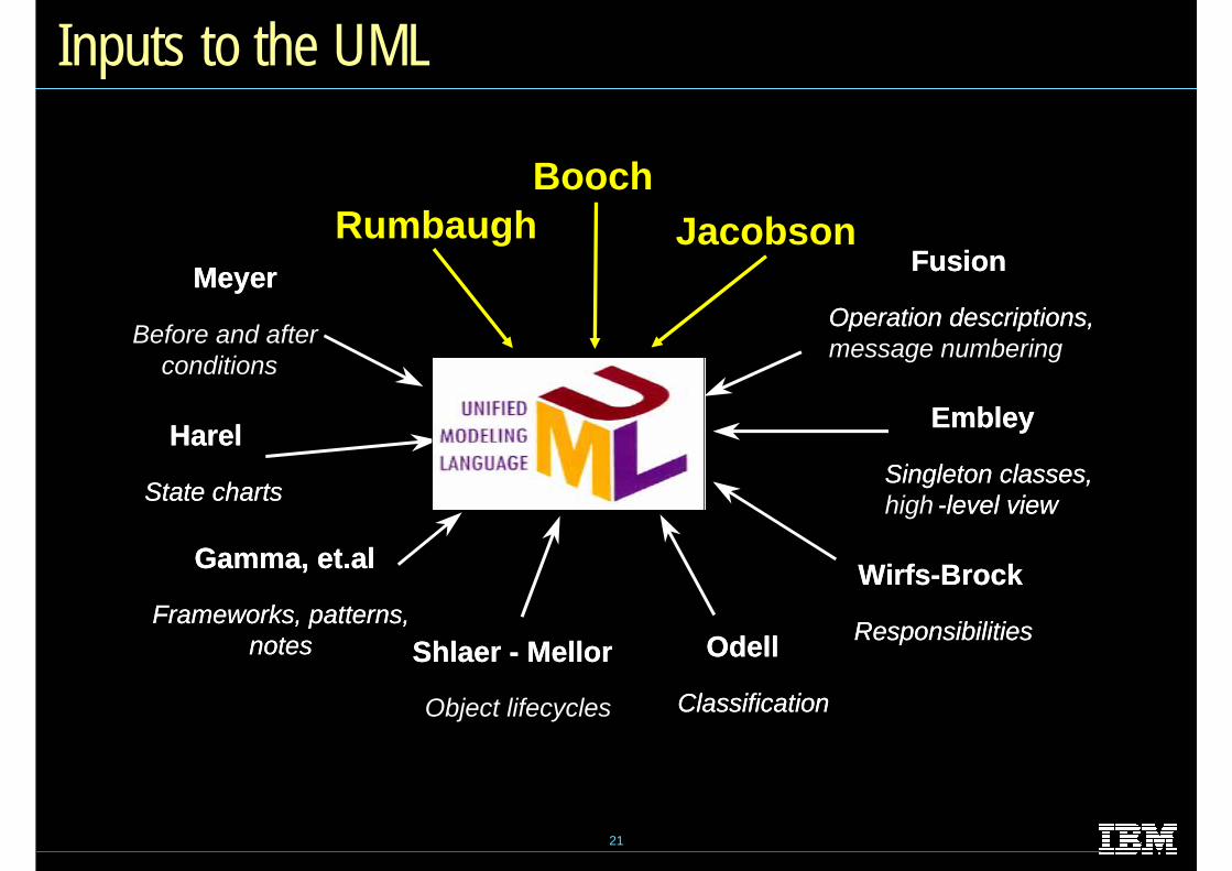
Inputs to the UML
Fusion
Operation descriptions,message numbering
Fusion
Operation descriptions,Meyer
Before and after conditions
Meyer
Harel
State charts
Harel
State charts
Wirfs-Brock
Responsibilities
Wirfs-Brock
Responsibilities
Embley
Singleton classes, high -level view
Embley
Singleton classes, -level view
Odell
Classification
Odell
Classification
Shlaer - Mellor
Object lifecycles
Shlaer - Mellor
Gamma, et.al
Frameworks, patterns,notes
Gamma, et.al
Frameworks, patterns,notes
BoochRumbaugh Jacobson

22
What is modeling?Four principles of visual modelingThe UMLProcess and visual modeling
Where Are We?
23
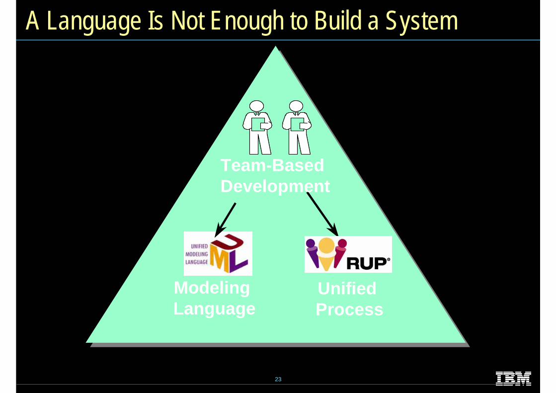
A Language Is Not Enough to Build a System
Modeling Language
Unified Process
Team-Based Development
24
What Type of Process Most Benefits the UML?
The UML is largely process independent. A process fully benefits from the UML when the process is:
Use-case drivenArchitecture-centricIterative and incremental

25
A Use-Case Driven Process
Use cases defined for a system are the basis for the entire development process.Benefits of use cases:
Concise, simple, and understandable by a wide range of stakeholders.Help synchronize the content of different models.
Withdraw MoneyWithdraw Money
CustomerCustomerCheck BalanceCheck Balance

26
An Architecture-Centric Process
A system’s architecture is used as a primary artifact for conceptualizing, constructing, managing, and evolving the system under development.Benefits:
Intellectual control over a project to manage its complexity and to maintain system integrity.Effective basis for large-scale reuse.A basis for project management.Assistance in component-based development.

27
An Iterative and Incremental Process
Critical risks are resolved before making large investments. Initial iterations enable early user feedback. Testing and integration are continuous. Objective milestones focus on the short term.Progress is measured by assessing implementations.Partial implementations can be deployed.

28
Iterative Development
Earliest iterations address greatest risks.Each iteration produces an executable release, an additional increment of the system.Each iteration includes integration and test.
T I M E
Iteration 1 Iteration 2 Iteration 3
IC
DR
TI
CD
R
TI
CD
R
T
29
Review
What is a model?What are the four principles of modeling? Describe each one.What is the UML? Describe each of its four benefits.What process characteristics best fit the UML? Describe each characteristic.What is an iteration?