estimates of the atmospheric transfer function at shf and ehf · presentation to estimates of the...
TRANSCRIPT
NTIA-REPORT-78-8
Estimatesof the Atmospheric
Transfer Functionat SHF and EHF
E.J.Dutton
H. T. Dougherty
U.S. DEPARTMENT OF COMMERCEJuanita M. Kreps, Secretary
Henry Geller. Assistant Secretaryfor Communications and Information
August 1978

TABLE OF CONTE!'rTS
LIST OF FIGURES
LIST OF TABLES
ABSTRACT
Page
v
v
1
INTRODUCTION1.
1.1.1.2.1. 3.1.4.
The Channel Transfer FunctionThe Attenuation FunctionThe Phase Delay FunctionTransfer Function Limitations
1
2235
2. ATTENUATION AND PHASE DELAY ESTIMATES FOR 10 TO 45 GHz
2.1. Clear-Sky Attenuation2.2. Attenuation By Clouds2.3. Attenuation By Precipitation2.4. Total Attenuation2.5. Phase Delays
6
789
1113
ATTENUATION AND PHASE DELAY ESTIMATES FOR 45 TO 350 GHz
3.1. Clear-Sky Effects3.2. Cloud Effects3.3. Rain Effects
3.
4.
5.
3.3.1.3.3.2.
CONCLUSION
REFERENCES
Phase delay by rainfallAttenuation by rainfall
iii
15
172021
2325
25
27
LIST OF FIGURES
Figure 1. Sea-level attenuation coefficients, in decibels perkilometer, versus frequency.
Figure 2. Predicted total attenuation, Tr(f) in decibels, versusfrequency for an earth/space path.
Figure 3. The clear-sky attenuation coeffieient (dB/km) due togaseous absorption (by water vapor and oxygen) atsea level.
Figure 4. The clear-sky phase-delay coeffieient (rad/km) due togaseous absorption (by water vapor and oxygen) at sealevel.
Figure 5. The complex refractive index of water versus frequency.
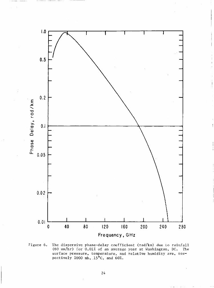
Figure 6. The dispersive phase-delay coefficient (rad/km) due torainfall (60 mm/hr) for 0.01% of an average year atWashington, DC.
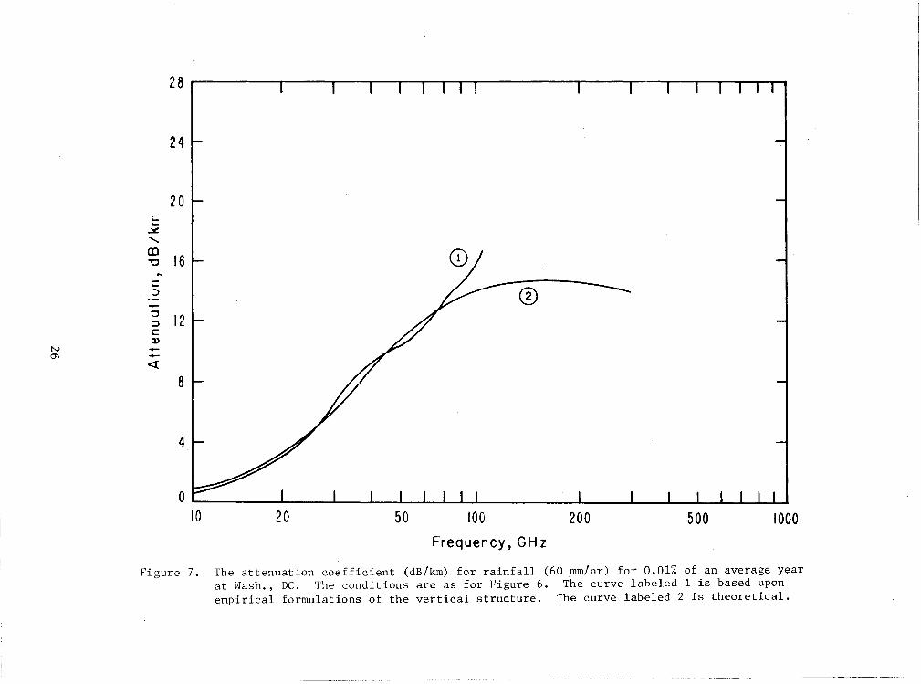
Figure 7. The attenuation coefficient (dB/km) for rainfall(60 mm/hr) for 0.01% of an average year atWashington, DC.
LIST OF TABLES
Table I. Atmospheric Attenuation, Tr(f) In Decibels, For AnEarth/Satellite System At Selected Frequencies As AFunction Of Initial Elevation Angle 80 , And Forp Percent Of An Average Year Near Washington, DC.
Table II. Atmospheric Phase Delay, ~r(f)-kor In Radians, ForAn Earth/Satellite System At Selected Frequencies,As A Function Of Initial Elevation .Angle 80 , And Forp Percent Of An Average Year Near Washington, DC.
Table III. Attenuation and Phase-Delay Coefficients Due ToClouds At 30°C.
v
Page
4
12
18
20
22
24
26
14
16
21


ESTIMATES OF THE ATMOSPHERIC T~~SFER FUNCTIONAT SHF AND EHF
by,'~
E. J. Dutton and H. T. Dougherty
ABSTRACT
Known theory is applied to examine the channeltransfer function for earth/space propagation pathsthrough the atmosphere and over t he frequency rangefrom 10 to 350 GHz. The associated attenuation andphase-delay characteristics are separated into thecontributions of the clear-sky, clouds, and rainfall.From the available meteorological data, the totalpath attenuation and phase-delay is estimated overthe frequency range from 10 to 45 IGHz for selectedvalues of the initial elevation angles from a groundstation near Washington, DC.
The associated attenuation coefficients (dB/km)and phase-delay coefficients (rad/km) attributableto the clear air, clouds, and rainfall are also described for frequencies up to 350 GHz.
Key Words: Atmospheric attenuation, atmospheric phasedelay,microwave frequencies, millimeterwaves, clear-air effects, effects of clouds,effects of rainfall.
1. INTRODUCTION
With the approach of the General World Administrative Radio Conference in
1979 (GWARC-79), there has been an increasing interest in the further develop
ment of frequency allocations above 10 GHz. One factor of concern in any
expansion of radio services into this relatively unused portion of the radio
s pect rum is the role of the atmosphere. The purpose of this report is to
present some quantitative estimates of the c.haracteristics of the atmosphere
that are significant for radio wave propagation and telecommunication system
performance above 10 GHz and below 350 GHz •
....~'The authors are with the Institute for Telecommunication Sciences, NationalTelecommunications and Information Administration, U. S. Department ofCommerce, Boulder, CO 80303.
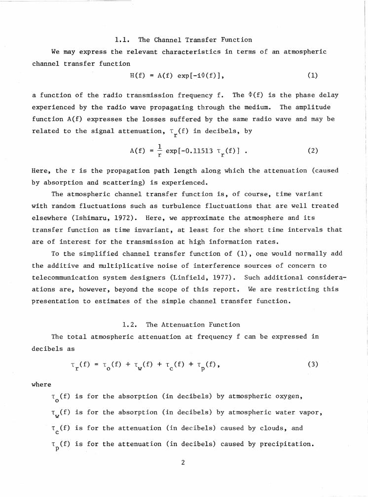
1.1. The Channel Transfer Function
We may express the relevant characteristics in terms of an atmospheric
channel transfer function
R(f) = A(f) exp[-i~(f)], (1)
a function of the radio transmission frequency f. The ~(f) is the phase delay
experienced by the radio wave propagating through the medium. The amplitude
function A(f) expresses the losses suffered by the same radio wave and may be
related to the signal attenuation, T (f) in decibels, byr
1A(f) = - exp[-O.ll5l3 T (f)] •
r r(2)
Here, the r is the propagation path length along which the attenuation (caused
by absorption and scattering) is experienced.
The atmospheric channel transfer function is, of course, time variant
with random fluctuations such as turbulence fluctuations that are well treated
elsewhere (Ishimaru, 1972). Here, we approximate the atmosphere and its
transfer function as time invariant, at least for the short time intervals that
are of interest for the transmission at high information rates.
To the simplified channel transfer function of (1), one would normally add
the additive and multiplicative noise of interference sources of concern to
telecommunication system designers (Linfield, 1977). Such additional considera
ations are, however, beyond the scope of this report. We are restricting this
presentation to estimates of the simple channel transfer function.
1.2. The Attenuation Function
The total atmospheric attenuation at frequency f can be expressed in
decibels as
T (f) T (f) + T (f) + T (f) + T (f), (3)r o w c p
where
T (f) is for the absorption (in decibels) by atmospheric oxygen,0
T (f) is for the absorption (in decibels) by atmospheric water vapor,w
T (f) is for the attenuation (in decibels) caused by clouds, andc
T (f) is for the attenuation (in decibels) caused by precipitation.p
2

The r subscript on the left-hand side of (3) is a reminder that attenuation
is determined for the entire path although the terms on the right-hand side
of (3) each have an associated £, not necessarily equal to r or each other.
For exampLe , for the oxygen and water vapor terms of (3), the appropriate
common Q, is that portion of r within the gaseous (clear-sky) atmosphere.
The appropriate £ for the cloud attenuation term is that portion of r within
the cloud. The appropriate £ for the precipitation term of (3) is that
portion of r within the region of precipitation.
Figure 1 is an over-all view of the atmospheric attenuation coefficients
(in decibels per kilometer) at sea level, adapted from Zuffrey (1972); see
also CCIR (1978). The continuous-line curve is a plot of the attenuation
coefficient for the gaseous (clear-sky) atmosphere (for a temperature of 20°C
and 7.5 gm/m3
of water vapor density). For frequencies below about 350 GHz,
this cLear-esky attenuation is primarily due to the absorption of radio energy
by oxyge.n and water vapor, as in (3). The dot-dash curve of attenuation
coefficient versus frequency is that for cLoud or fog (with 0.1 gm/m3 of
water in droplet form). The dotted curves are the attenuation coefficients
for various rainfall rates. The 150 mm/hr is an extremely high rainfall rate
rarely encountered in the U.S.; the 25 nnn/hr is a moderate rainfall rate
exceeded in the southeastern U.s. for a cumulative total of about 8 hrs/yr;
the 0.25 mm/hr is an extremely light rainfall.
Since the gaseous atmosphere is always prese.nt, the clouds or fog
commonly present, and the various rainfall rates only intermittently
present, their relative importance can be obscured by the presentation
of Figure 1. Further, the appropriate £ for the gaseous atmosphere will
correspond to the entire propagation path Length within the atmosphere.
For the highest rainfall rates, the aasocLated £ can be much less.
1.3. The Phase Delay Function
There is, of course, the same association of .R,'s with the sources of
the radio wave phase delay. The total phase delay at frequency f can be
expressed in radians as
~ (f) = k r + ~N(f) + ~ (f) + ~ (f)roc p
3
(4)

Wavelength
lcm lmm 100fL 10fL lfL1000 1000--
EIgm/m 3 _ ..:>£ O.<,
CD"U 100c: ..- 150mm/hrc:Q) .
cO2o °2- ... .- ....>": .... ..........Q)0 .u .c: /
CO20- /0::Jc: .....Q) ....- ·0.25 mm/hr ••- ...~ '.Q)
j.> .'.Q) 0.1 J. 0.1--.J
0 •Q) ;.:.(f)
. .0.01 I: 0.01
10 106
Frequency in
Figure 1. Sea-level attenuation coefficients, in decibels per kilometer, versus frequency for: thegaseous atmosphere (the continuous line curve for 20°C temperature and water vapor densityof 7.5 gm/m 3 ) ; clouds (the dot-dash curve for water droplets 0.1 gm/m 3 ) , and variousrainfall rates (the dotted curve),
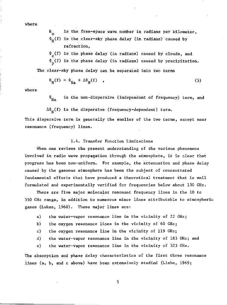
where
k is the free-space wave number in radians per kilometer,0
~N(f) is the clear-sky phase delay (in radians) caused by
refraction,
~ (f) is the phase delay (in radians) caused by clouds, andc~ (f) is the phase delay (in radians) caused by precipitation.p
The clear-sky phase delay can be separated into two terms
(5)
where
~Na is the non-dispersive (independent of frequency) term, and
~~N(f) is the dispersive (frequency-dependent) term.
This dispersive term is generally the smal.Ler of the two terms, except near
resonance (frequency) lines.
1.4. Transfer Function Limitations
When one reviews the present understanding of the various phenomena
involved in radio wave propagation through the atmosphere, it is clear that
progress has been non-uniform. For example, the attenuation and phase delay
caused by the gaseous atmosphere has been the subject of concentrated
fundamental efforts that have produced a theoretical treatment that is well
formulated and experimentally verified for frequencies below about 130 GHz.
There are five major molecular resonant frequency lines in the 10 to
350 GHz range, in addition to numerous minor lines attributable to atmospheric
gases (Lukes, 1968). These major lines are:
a) the water-vapor resonance line in the vicinity of 22 GHz;
b) the oxygen resonance lines in the vicinity of 60 GHz;
c) the oxygen resonance line in the vicinity of 119 GHz;
d) the water-vapor resonance line in the vicinity of 183 GHz; and
e) the water-vapor resonance line in the vicinity of 323 GHz.
The absorption and phase delay characteristics of the first three resonance
lines (a, b, and c above) have been extensively studied (Liebe, 1969;
5

Liebe, et a1., 1977). Further, estimates of the attenuation and phase
delay -characteristics of molecular oxygen resonances in the vicinity of
both 60 and 119 GHz have been presented for the earth/space systems
(Liebe, et a1., 1977; Liebe and Hopponen, 1977). An approximate formulation
for both the attenuation and phase delay caused by oxygen is available for
computer-progrannning purposes over the range of 50 to 120 GHz (Ott and
Thompson, 1976).
Similarly, for the attenuation and phase delay caused by raindrops, the
appropriate theory must be modified as the Rayleigh condition (that the rain
drop dimensions are small relative to the radio wavelength) becomes less
applicable for frequencies exceeding about 45 GHz. Further, the polarization
dependent effects of the non-sphericity of raindrops, their tilt angles, and
the vertical structure of rainstorms all combine to create increasing uncer
tainties above about 45 GHz.
For these reasons we have divided our presentation according to two fre
quency ranges:
1) At 10 to 45 GHz, there is sufficient relevant data to permit some
extrapolation of theory and to determine esti
mates of total attenuation and phase delay for
earth/space systems.
2) At 45 to 350 GHz,the situation is mixed. For clear-sky conditions
the prediction procedures from 45 to 130 GHz are so
well developed that the attenuation and phase delays
for earth/space systems are already available in the
literature. For rainfall, the available data and
theory can be applied to about 80 GHz. Above 130
GHz, the theory is sufficiently undeveloped and the
experimental data is so limited that of the attenua
tion coefficient (dB/km) and phase-delay coefficients
(rad/km) have only been estimated.
2. ATTENUATION AND PHASE DELAY ESTIMATES FOR 10 TO 45 GHz
The attenuation function for the entire propagation path is given in (3)
in terms of contributory components, each of which is a path-integrated
quantity. For example, the attenuation due to the oxygen in the atmosphere
6

is given in decibels by
T (f) =o J
oa (f) dL
o(6)
The quantity a (f) is the absorption coefficient of oxygen per kilometer ofo
path length within the atmosphere. For the attenuation due to water vapor in
the atmosphere, T (f), there is a corresponding a (f). For the attenuationw . wby cloud, T (f), the corresponding attenuation coefficient per kilometer of
cpath length within cloud is identified as a (f). For the attenuation by
cprecipitation, T (f), the corresponding coefficient a (f), is attenuation per
p pkilometer of path length through the precipitation region.
2.1. Clear-Sky Attenuation
The attenuation due to clear-sky conditions (i.e., due to absorption
by the gaseous constituents of the atmosphere) is that indicated as the
(7)+0.34f2
2c
a (f) =o
sum of two terms in (3), T (f) due to oxygen and T (f) due to water vapor.o w
For the frequency region 10 to 45 GHz, Van Vleck (1947a) gives a formulation
for the oxygen absorption per unit length, a (f), aso
[
LlVl tW22 +
L+6v2 (2+ i)2+ Llv2c 2 1 c 2
The 6Vl and 6V2 are line widths whose values may be found in Bean and Dutton
(196S), and c is the velocity of light in vacuo. Van Vleck's (1947b) form
for the water vapor absorption per unit length a (f), is given asw
a (f) = a l(f) + a 2(f) ,w w w(Sa)
where
(8b)
20.05f Llv42
c(8c)
7
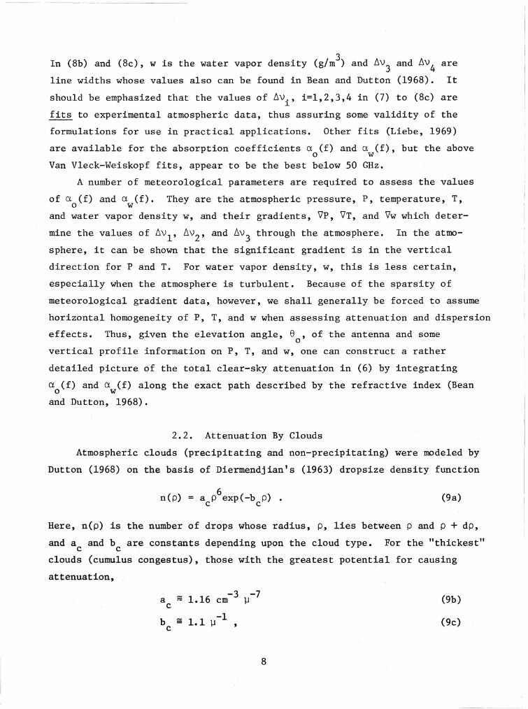
In (8b) and (8e), w is the water vapor density (g/m3) and ~V3 and ~V4 are
line widths whose values also can be found in Bean and Dutton (1968). It
should be emphasized that the values of ~v., i=1,2,3,4 in (7) to (8c) are1
fits to experimental atmospheric data, thus assuring some validity of the
formulations for use in practical applications. Other fits (Liebe, 1969)
are available for the absorption coefficients a (f) and a (f), but the aboveo w
Van Vleck-Weiskopf fits, appear to be the best below 50 GHz.
A number of meteorological parameters are required to assess the values
of a (f) and a (f). They are the atmospheric pressure, P, temperature, T,o w
and water vapor density w, and their gradients, V'P, V'T, and \/w which deter-
mine the values of ~Vl' ~V2' and ~V3 through the atmosphere. In the atmo
sphere, it can be shown that the significant gradient is in the vertical
direction for P and T. For water vapor density, w, this is less certain,
especially when the atmosphere is turbulent. Because of the sparsity of
meteorological gradient data, however, we shall generally be forced to assume
horizontal homogeneity of P, T, and w when assessing attenuation and dispersion
effects. Thus, given the elevation angle, e , of the antenna and someo
vertical profile information on P, T, and w, one can construct a rather
detailed picture of the total clear-sky attenuation in (6) by integrating
a (f) and a (f) along the exact path described by the refractive index (Beano w
and Dutton, 1968).
2.2. Attenuation By Clouds
Atmospheric clouds (precipitating and non-precipitating) were modeled by
Dutton (1968) on the basis of Diermendjian's (1963) dropsize density function
n(p) 6a p exp(-b p) •c c
(9a)
Here, n(p) is the number of drops whose radius, P, lies between p and p + dp,
and a and b are constants depending upon the cloud type. For the "thickest"c c
clouds (cumulus congestus), those with the greatest potential for causing
attenuation,
a - 1.16 cm-3 11-7c
b - 1.1 11-1 ,c
8
(9b)
(9c)

for n(p) measured in cm- 3 ].1-1 and p in microns (].1). The expression (9a) is,
essentially, a non-normalized gamma-distribu.tion density function. If we
assume (9a), (9b), and (9c) apply to all cloudiness along the path (a worst
case situation) then, using the Rayleigh-region approximations, we can obtain
the attenuation coefficient for clouds, the attenuation per kilometer,
fDa (f) = 0.560 2 2
c (C+2) +D
In (10), the frequency is in gigahertz and the C and D are the real and
imaginary parts of the dielectric coefficien.t of water,
(10)
E: = C-iD (11)
The dielectric constant of (11) is related to the index of refraction of water,
m, assuming no magnetic effects, by
m=/~
Thus, m is also a complex number,
m = mt- im" •
(12a)
(12b)
In spLte of the terminology "dielectric constant", the C and D, and hence m"
and m" are frequency dependent.
Goldstein (1951), has indicated that a mathematical relationship,
between and frequency, called the Debye formula, represents a good fit
to data for frequencies up to about 30 GHz used in SHF rainfall-effect
computations. At EHF, however, not that many data have been taken. Using
a relative wealth of data at optical frequencies, Ray (1972) has essentially
"blended in" the EHF region by joining the optical and SHF results. As a
consequence, he obtains curves for EHF that are closely approximated by
the Debye formulation.
2.3. Attenuation By Precipitation
The major contributor to attenuation by precipitation is that attributable
to rainfall. For telecommunication purposes and for studying long-term
effects, Rice and Holmberg (1973) have treated all precipitation as if
it were effectively rainfall. The attenuation coefficient for rain, a(f,h)
in decibels per kilometer, is a function of the transmission frequency f
9

and the elevation h of the point of observation above the surface (Dutton
and Dougherty 1973)
where
a(f ,h)b (f)
"i (f) [L(h)] 1 (13a)
a1(f) is a frequency-dependent coefficient (dB/km) determined (Dutton
and Dougherty, 1973) with data from 1.29 to 94 GHz (Crane, 1966);
bl(f) is a frequency-dependent exponent also determined by regression
analysis of Crane's data (1966);
L(h) is liquid water content of the rainfall (g/m3
) at a height h
above the surface.
The vertical structure of the liquid water content, L(h), is determined by
rainfall rate R at the surface (h=O) and the mix of rainfall typeso
(Dutton, 1977a)
where
L(h) BL (h) + [ 1 - BJ L (h)c s
(13b)
B is the predicted convective ratio (the ratio of convective
rainfall to total rainfall (Rice and Holmberg, 1973);
L (h) is the convective rainfall vertical structure of liquid-waterc
content [i.e., the dominant term of (13b) for the highest
rainfall rates] (Dutton, 1967);
L (h) is the stratiform rainfall vertical structure of liquid-waterscontent (i.e., the dominant term of (13b) for the lighest
rainfall rates) (Dutton, 1971).
These vertical structures are predicted from the surface values of rainfall
rate, pressure, temperature, and the cloud- top height. These vertical
structures also include the Marshall-Palmer (1948) raindrop size distribution
where
n(p,h) = A(h) exp[-pB(h)] (14a),'"
B(h) 8.2[R(h)]-O.2l
10
-1nun (14b)
, Here, n(p ,h) is the number of raindrops with. radii between p and P + dP
millimeters at an elevation h above the surface. For terrestrial systems,
h~O and R(h)=R and A = 16000 mm-1m-3 For earth/space systems, however, weo
approximate the dropsize distribution by again using the surface rainfall
rate R to determine B, but then we take A to be only 8000mm-1m-3 (Dutton,o
1977a) •
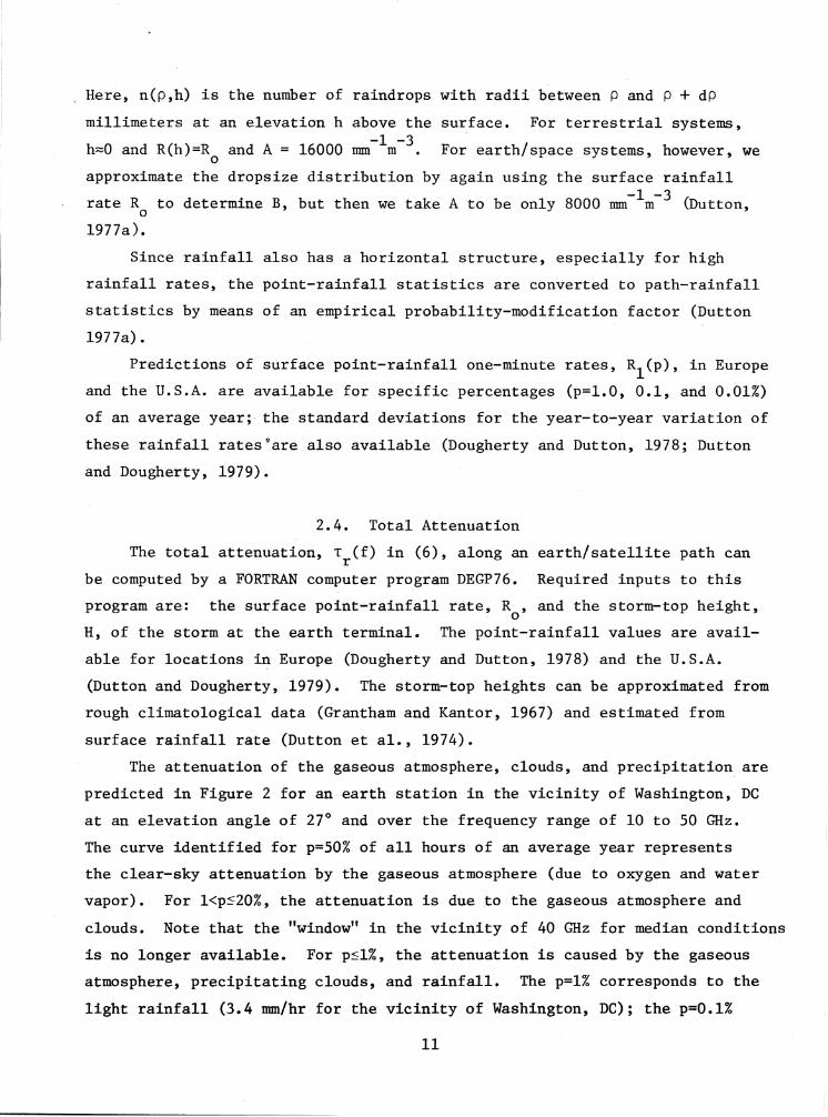
Since rainfall also has a horizontal structure, especially for high
rainfall rates, the point-rainfall statistics are converted to path-rainfall
statistics by means of an empirical probability-modification factor (Dutton
1977a).
Predictions of surface point-rainfall one-minute rates, R1(p),
in Europe
and the U.S.A. are available for specific percentages (p=l.O, 0.1, and 0.01%)
of an average year;' the standard deviations for the year-to-year variation of
these rainfall rates~are also available (Dougherty and Dutton, 1978; Dutton
and Dougherty, 1979).
2.4. Total Attenuation
The total attenuation, T (f) in (6), along an earth/satellite path canr
be computed by a FORTRAN computer program DEGP76. Required inputs to this
program are: the surface point-rainfall rate, R , and the storm-top height,o
H, of the storm at the earth terminal. The point-rainfall values are avail-
able for locations in Europe (Dougherty and Dutton, 1978) and the U.S.A.
(Dutton and Dougherty, 1979). The storm-top heights can be approximated from
rough' climatological data (Grantham and Kantor, 1967) and estimated from
surface rainfall rate (Dutton et al., 1974).
The attenuation of the gaseous atmosphere, clouds, and precipitation are
predicted in Figure 2 for an earth station in the vicinity of Washington, DC
at an elevation angle of 27° and over the frequency range of 10 to 50 GHz.
The curve identified for p=50% of all hours of an average year represents
the clear-sky attenuation by the gaseous atmosphere (due to oxygen and water
vapor). For l<ps20%, the attenuation is due .to the gaseous atmosphere and
clouds. Note that the "window" in the vicinity of 40 GHz for median conditions
is no longer available. For p~l%, the attenuation is caused by the gaseous
atmosphere, precipitating clouds, and rainfall. The p=l% corresponds to the
light rainfall (3.4 mm/hr for the vicinity of Washington, DC); the p=O.l%
11

30
p=50%
40
---+-.-.------l
30Frequency in Gigahertz
20
-F-H+.-I-+~._---------------
IL----L-_-J.J.~~~__J.... ......L.... ..L_ L_______'_ ~
10
5
2
3
20 f--------r--
30
50 r------r----,----~--------r-~--~--_.,.._.___--___.
....o~
s~
(/)~.8 c'(3 0
~ C
.17;; rc ::3o 0~Io::3
&i<t~Oo C.~ ~
~ ....a.Q)(/)a..o a.
E~.Q
"0Q)
"0Q)Q)o)(
W
.....N
Figure 2. Predicted total attenuation, Tr(f) in decibels, versus frequency for an earth/spacepath. The earth-station elevation angle is 8=27°, The p=50% curve is that for clearsky conditions. The curves for 1<p<20% show the added effects of clouds. For p~l%
the increased attenuation is due to rainfall.

corresponds to moderate rainfall (15 nnn/hr); the p=Q.01% corresponds to a
heavy rainfall (60 mm/hr). Although these curves are for an average year,
the year-to-year variation with rainfall can be determined from the year-to
year variability (Dougherty and Dutton, 1978; Dutton and Dougherty, 1979).
For other values of the elevation angle 8 and for percentages of 1%
or greater, the values T(p,8) may be determined from the T(p, 8=27°) in
Figure 2 by
T(p,8) = 0.454 T(p,8=27°) csc8 , p 1%, 8>5°. (15)
The limitation 8>5° avoids atmospheric stratification effects and other
considerations [Dutton and Dougherty, 1973]. Table I lists the total attenua
tion values for other elevation angles and for selected frequencies and per
centages of an average year.
2.5. Phase Delays
The phase delays in (4) due to clear air, clouds, and precipitation
(turbulence not included) can be shown to be given approximately by
r r~N(f) = 10-6k
o J Na d~ + 10-6ko J
o 0
~N(f) d~ = ~N + ~~N(f)
a(16a)
and
~ (f) + ~ (f)c P
in radians. Here:
rJ m"'(f) d~
eo
(16b)
Na
is the portion of the clear air refractivity which is frequency
independent (Bean and Dutton, 1968),
~(f) is the dispersive or frequency dependent portion of the clear
air refractivity (Liebe, 1969),
m"'(f) is the increase in the (equivalent) refractivity of thee
atmosphere when it is raining (Zuffery, 1972), and
¢ (f) is the phase-delay coefficient (rad/km) due to cloudsc
(precipitating or non-precipitating).
13

TABLE I
Atmospheric Attenuation, Tr(f) In Decibels, For An Earth/Satellite System AtSelected Frequencies, As A Function Of Initial Elevation Angle 8 , And For p
Percent Of An Average Year Near Washington, DC 0
Frequency Initial Angle Percent Of An Average Year, p
f, GHz 8 , deg. 0.01 0.1 1 10 500
30 5 126.282'8 77.3162 51.5731 41.1809 14.389115 98.9060 35.0715 18.8881 14.8613 5.119830 78.3634 18.4662 9.8492 7.7474 2.665845 74.8127 13.0725 6.9739 5.4854 1.8871
25 5 89.5768 55.4456 37.0657 31.1031 13.633815 69.6324 24.6697 13.5210 11.1932 4.833630 55.0351 12.8984 7.0493 5.8339 2.515845 52.8559 9.1308 4.9913 4.1305 1.7807
22.235 5 74.2669 47.1732 32.4512 28.5570 15.556115 56.5152 20.5867 11.7833 20.2486 5.512030 44.3149 10.7310 6.1416 5.3402 2.868745 42.7171 7.5964 4.3483 3.7808 2.0305
20 5 58.0667 36.0622 23.9755 20.4607 9.705915 45.2487 15.8805 8.7305 7.3586 3.442130 35.6111 8.2701 4.5516 3.8352 1.791645 34.7351 5.8544 3.2228 2.7154 1.2682
15 5 32.3261 19.8253 12.8626 10.7374 4.610215 25.7103 8.7888 4.6974 3.8741 1.645330 20.1184 4.5859 2.4497 2.0199 0.857045 20.1902 3.2464 1.7346 1.4302 0.6067
10 5 14.0668 8.8920 6.1078 5.2957 2.722215 10.3624 3.7589 2.2253 1.9122 0.974530 8.3827 1.9584 1.1606 0.9971 0.507745 7.4664 1.3865 0.8218 0.7060 0.3595
14
The first term of (16a) can be evaluated in the Washington, DC area to be
(Bean and Thayer, 1963)
r¢N (f) = 10-6k f N d~ = 2.096xl04f csc 8,
o aa 0
(17)
where 8 is the earth-station antenna elevation angle and f is the trans
mission frequency in gigahertz. The second term of (16a) can be evaluated
in radians using mean atmospheric conditions and a Lorentz line-shape
(Liebe, 1969).
(18)csc 8.f(f -f)
q
(f -f)2+O. 0984q
6N(f)d~ - 0.1731 ------~~-----
o
r
f
The frequency f is in gigahertz and f =22.23515 GHz is the water-vaporq
resonance line. The phase delay (in radians) due to cloud is
¢ (f)c
(19a)o
and2
¢ (f) = 2.l5(10)-2f (C-l) (C+2) + Dc (C+2)2 + D2
(19b)
in radians per kilometer. Again, the frequency f is in gigahertz and the
parameters C and D are as defined by (11).
The total phase delay in excess of the first term of (4), k r in radians,o
is listed for an earth-space path and for selected values of elevation angle
and frequency in Table II.
3. ATTENUATION AND PHASE DELAY ESTIMATES FOR 45 TO 350 GHz
Estimates of the clear-sky attenuation and phase delay for the frequency
range 45 to 130 GHz for various initial elevations (h~O) within the atmo
sphere, and for zenith (8=90°) or horizontal (8=0°) paths are available in
detail [Liebe, 1969; Liebe et al., 1977].
For the frequency range from 130 to 350 GHz, the major contributions to
the clear-sky attenuation (absorption by the gaseous atmosphere) are primarily
caused by absorption at the water-vapor resonance lines in the vicinities of
15

TABLE II
Atmospheric Phase-Delay, ~r(f)-kor In Radians, For An Earth/Satellite SystemAt Selected Frequencies, As A ,Function Of Initial Elevation Angle 8 , And For
p Percent Of An Average Year Near Washington, DC 0
Frequency lnitia1 Angle Percent Of An Average Year, p
f, GHz e , deg. 0.01 0.1 1.0 10 500
";~
30 5 20.4116 8.8890 3.2931 -1.0741 -2.591315 21.3403 5.1558 1.1949 -0.4082 -0.961930 18.1930 2.7333 0.6175 -0.2156 -0.503345 17.9811 1.9337 0.4365 -0.1530 -0.3566
25 5 9.7110 4.2223 -0.1861 -3.6977 -4.923415 12.4790 2.9643 -0.1112 -1.3974 -1.843830 11.0588 1.5502 -0.0653 -0.73~7 -0.965745 11.2089 1.0960 -0.0472 -0.5202 -0.6847
22.235 5 12.7872 7.8882 4.1318 1.0732 0.002715 12.5897 4.1245 1.5095 0.3905 0.001030 10.5597 2.1477 0.7844 0.2029 0.000545 10.5282 1.5198 0.5551 0.1436 0.0004
20 5 15.7496 11.3400 8.1060 5.4033 4.455215 12.8575 5.2624 3.0071 2.0189 1.674130 10.2361 2.7421 1.5698 1.0563 0.877245 10.0430 1.9414 1.1118 0.7484 0.6216
15 5 9.5122 6.1202 4.0114 2.0705 1.385915 8.6521 2.9812 1.4733 0.7635 0.514630 7.0097 1.5554 0.7674 0.3986 0.269245 7.1753 1.0109 0.5433 0.2823 0.1908
10 5 7.2795 3.6210 2.2486 1.0047 0.°563815 6.5769 1.7123 0.8203 0.3684 0.209030 5.6639 0.8907 0.4270 0.1922 0.109445 5.1589 0.6304 0.3022 0.1361 0.0775
* . funct Lon dThe nature of the Lorentz line shape is such that the phase-delay unct10n 1nt he clear air becomes negative above the resonant frequency f q:=;22.235 GHz(Liebe, 1969). This trend persists only until higher resonance frequenciesare approached and is analagous to the situation for higher frequencies shownin figure 4.
16

183 and 323 GHz. Further, clouds and precipitation continue to playa signif
icant role. However, the problem of estimating the total attenuation, as in
(3), or the total phase delay, as in (4), is currently hampered by the fact
that water vapor is the most highly variable constituent of the atmosphere.
Further, there are not sufficient data at these frequencies to determine
empirically-defined coefficients for vertical structures, such as in (13a).
Nevertheless, we can determine the corresponding attenuation and phase delay
coefficients (in dB/km and rad/km).
3.1. Clear-Sky Effects
When the dispersive phase-delay coefficient, ~¢Nw in radians/km, caused
by water vapor is given by the Lorentz line-shape formula (Liebe, 1969), a
simple relationship,
(21)a (f)w
(f -f)o
8.686~¢N (f) = ~¢N(f) - ~¢N (f) =~~w 0
can be established between:
a (f), the attenuation coefficient in dB/km;w
atmospheric oxygen; and
~¢N (f), the portion of the dispersive phase delay caused byo
~¢N(f), the total dispersive phase-delay coefficients in radians/km.
However, one of the most straightforward formulations for attenuation L (f)w
is that of Ulaby and Straiton (1970) who do not use the Lorentz formulation.
Instead they use the Van Vleck-Weiskopf line-shape formulation. Nonetheless
it is assumed here that the Van Vleck-Weiskopf line-shape formulation for the
attenuation of Ulaby and Straiton (1970) can be used in conjunction with
(21) to predict ~¢Nw(f) due to water vapor in the 130 to 350 GHz region.
The oxygen-caused phase-delay and attenuation coefficients ~¢N (f) and ao(f),
can be obtained directly from expressions given by Ott and Thogpson (1976).
Therefore, we have established procedures for predicting the values of
the ~¢NCf), the aw(f) , and the aoCf) for the 50 to 350 GHz frequency region.
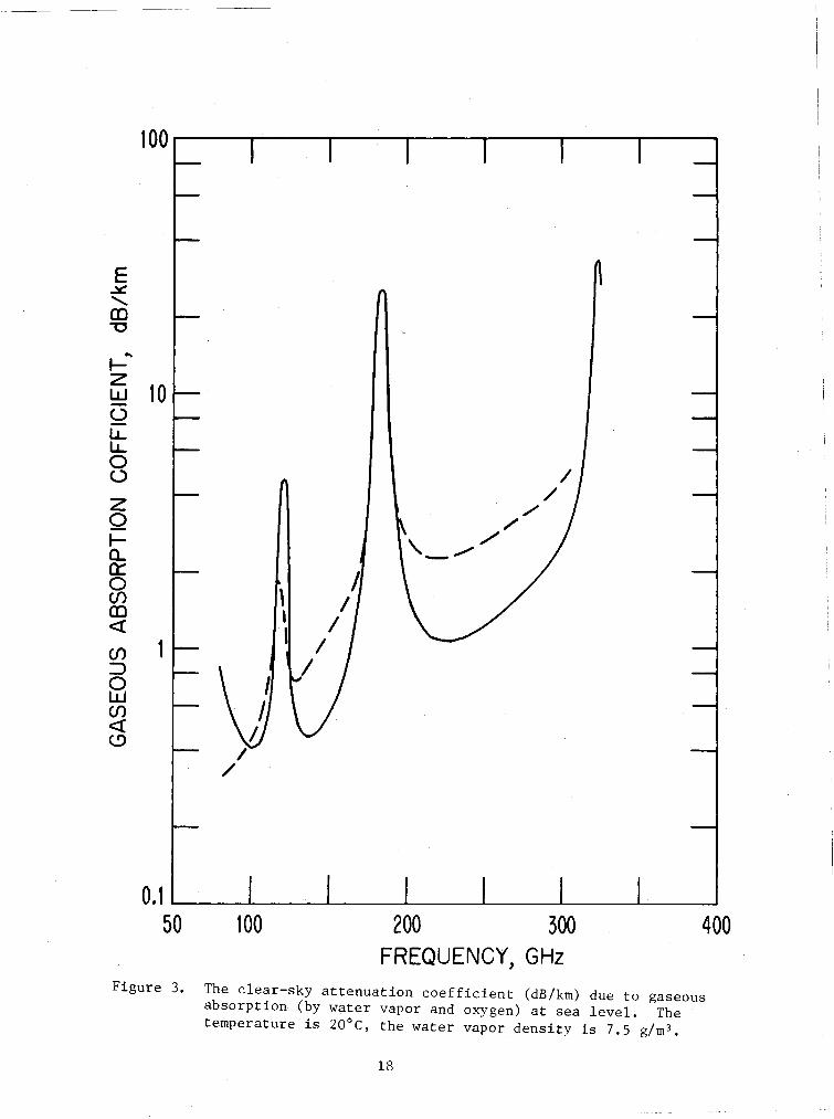
Figures 3 and 4 show the results of calculations for a location having a
surface pressure of 1013.25 mb (sea level), a surface temperature of 20°C, and
a surface relative humidity of 43 percent. Figure 3 shows the sum of the two
17
100 ...----.,..--.,----.---,------r---.----,
10
//
./~ ,/\. /'- .",."
~/
//
/
\,I1
...~zw<..)
l.L.l.L.oozo~Q.a::o(j)CDc::x:(j):::>ow(j)c::x:<.9
4001000.1 L--..l.---L---L..----L------l.--L--..-------.J
50
Figure 3. The clear-sky attenuation coefficient (dB/km) due to gaseousabsorption (by water vapor and oxygen) at sea level. Thetemperature is 20°C, the water vapor density is 7.5 g/m3.
18

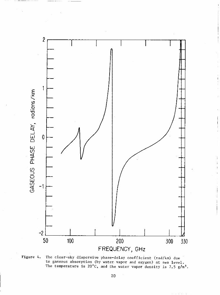
attenuations ex (f) and ex (f) over a surface link 1 km long; i.e. decibels ofo· w
attenuat:lon per kilometer versus frequency. Figure 4 shows the dispersive
phase delay ~epN(f) versus frequency, again over an assumed 1 km surface link
(or phasE~ delay in radians per kilometer). Only residual effects of the
60 GHz oxygen resonance are noted in both figures near 80 GHz. Additionally,
the two ~vater-vapor resonances have almost the same impact near their
respective resonances, whereas the 119 GHz oxygen resonance impact is far
less in both figures 3 and 4.
Recently Liebe and Gimmestad (1978) presented a detailed study of
cLea r-isky absorption properties. Their results are included in Figure 3
as a dashed-line curve.
3.2. Cloud Effects
The relatively straightforward formulations of section 2.2 for cloud
effects c.an be used, if we are in the so-called "Rayleigh" frequency region
(Bean et aL, , 1970). However, if we are in t he "Mie" region, the calcula
tions become vastly more complicated. The Rayleigh approximations are
roughly a.pplicable when
P f < 0.4 (22)
where p is a precipitation drop (assumed spherical) radius in centimeters
and f is the radio frequency in gigahertz. For clouds, the situation is
ameliorated to mainly Rayleigh-region computations, provided (9a) is assumed.
Furthermore, if the largest frequency considered, 350 GHz, is used in (22),
then a radius p = 11.4 1J is obtained. Combinfng this result with (9a), (9b),
(9c), and (22), yields the result that approxlmately 96 percent of all the
cloud droplets satisfy (22), even at 350 GHz. The percentage would be larger
at lower frequencies. This implies that for even the thickest clouds (with
greater percentages of large drops) and highest frequencies, the Rayleigh
region can be assumed to hold for cloud-effect computations.
The attenuation coefficient a, (f) and the phase delay coefficient ep (f)c c
from (10) and (19b) are applicable through 350 GHz. Table III list some
typical values.
As mentioned previously in Section 2.2, CoLds t efn (1951) presented the
Debye ' formula as a good fit to data for f requencf.es up to about 30 GHz and
19
----~------ ------ -- -- -----
2-----.---~---..,.--------r---._______._1
330300200FREQUENCY, GHz
100-2 L--_--L....-__---J'-__-L-__---L --L.-~
50
E.x:<,(J)c0
""00~
...~-.JW 00
w(f)
<tIQ...
(f):::>0w(f) -1<t<..9
Figure 4. The clear-sky dispersive phase-delay coefficient (rad/km) dueto gaseous absorption (by water· vapor and oxygen) at sea level.The temperature is 20 De, and the water vapor density is 7.5 g/m 3 •
20

TABLE III
Attenuation And Phase Delay CoefficientsDue To Clouds At 30°C
Frequency, f ~ (f) a (f)c c(GHz) (dB/km) (rad./km)
10 0.0211 0.0176
80 1.43 1.61
100 2.14 1.98
200 6.39 3.61
300 10.1 4.96
350 11.5 5.58
As mentLoned previously in Section 2.2, Goldstein (1951) presented
the DebYE~ formula as a good fit to data for frequencies up to about 30 GHz
and Ray (1972) has essentially "blended in" the EHF region by joining the
optical and SHF results. These refractive index results are illustrated
in ELgure 5 for a droplet temperature of 30°C. The dashed lines are Ray's
(1972) results, and the solid lines are obtained from the Debye formula using
Goldstein's (1951) constants. Based on Ray's (1972) work, then, it has been
assumed in the cloud and rain effects computations made herein that the
Debye formulation for the dielectric constant of water applies from 80 to
350 GHz.
3.3 Rain Effects
21

--r---_---- -10 ,----_r------,----.-----,----r------.-------,--,----,---,
xwoZH
0::W
~SLLo
w>~o<!0::LLW0::
1000100FREQUENCY, GHz
0.1 "------__L--__L------L._L--...JL..-_------JL..-__L---..L._~
10
Figure 5. The complex refractive index of water versus frequency. Theupper pair of curves are for the real term m'; the lower pairof curves are for the imaginary term mIt. The dashed-linecurves were determined by the Debye model (Goldstein, 1951);the solid-line curves were determined from Ray's model (1972).
22

3.3.1. Phase Delay By Rain£all
From the classic Mie (190,8) theory, Zuffery (1972) develops what is known
as the "forward scatter function" of a spherical water droplet impinged by
electromagnetic radiation. In an earlier expression, (12a) , we introduced
the comp l.ex refractive index, m, of a water droplet. Through an infinite
series representation involving spherical Bessel and Hankel functions, the m
is related to the forward scattering function. When several of these water
droplets are assumed randomly "embedded" in a slab of the atmospheric medium
of length d.Q" the "equivalent" (or essentially average) increase, m (f), ofe
the refractive index of the medium over that for clear air can be obtained by
integrating over the forward scattering functions of all droplets in the slab.
The reader interested in the theoretical development is referred to
reports such as that by Rogers and Olsen (1976). The increase in the complex
index of refraction, m (f), can be expressed ase
m (f) = m' (f) - im" (f)e e e
(23)
The real part of (23), mt(f), is directly related to the rain-caused phasee
delay, ~p(f) in (4), by
ep (f) = 10-6 kp 0
JQ, m' (f) dQ,e
o
where, again, k is the free-space wavenumber at frequency f, ep (f) is ino p
radians, and dt is the differential path length increment.
Results for a 1 km link with a surface ra.in rate of 60 mm/hr, a surface
temperature of 15°C, a surface pressure of 1000 ron, and a surface relative
humidity of 60° (roughly Washington, DC, for a. .01% of an average year) are
shown in Figure 6. The dropsize distribution used to determine ¢ (f) is thep
modified Harsha.Ll.e-Pal.mer distribution descr tbed in Section 2.3. The results,
unlike results at SHF, indicate that the phase-delay coefficient due to pre
cipitation, ¢ (f) in rad/km, decreases rather dramatically with frequency.p
Recalling Table III, the results for clouds in.crease with frequency rather
dramatically, implying that, at higher frequencies, the cloud effects could
indeed be the more important of the two as far as phase delay is concerned.
23
-~-- --- ---- - ---
2802402001601208040o
0.5
/.0 .----~--__""T--___r--_,_--_,_-- ......--...,
0.01
0.02
0.2E~
<,"00~
>. 0.10-Q)
0
Q)In0s:a.. 0.05
Frequency, GHz
Figure 6. The dispersive phase-delay coefficient (rad/km) due to rainfall(60 mm/hr) for 0.01% of an average year at Washington, DC. Thesurface pressure, temperature, and relative humidity are, respectively 1000 mb, 15°C, and 60%.
24

3.3.2. Attenuation By Rain~all
The imaginary part of (23), m~ (~f), is '(elated to t he rain-caused
attenuation, Tp(f), in (3) by
T (f) = 1.82042xlO-5fp-
J9t m" (f)o e
d,R, (25)
where f is the frequency in gigahertz. Fd.gure i? shows this attenuation for
a I km li.nk and the same conditions as in Figure 6; the values are plotted
from 10 to 300 GHz on the curve labeled 2. For the range 10 to 95 GHz, there
is a curve of attenuation labeled 1, based on the empirical SHF techniques
used in section 2.3. The two curves correspond reasonably closely to about
80 GHz, but then, at least for the remaining 15 GHz in common, the two curves
begin to diverge. Values from the theoretical curve labeled 2 thereafter tend
to plateau beyond 95 GHz and even to decrease slightly above about 150 GHz.
Rain attenuation remains a more dominant effect than cloud attenuation. This
is in contrast with the situation observed in the previous section on phase
delay.
4. CONCLUSION
The simple atmospheric channel trapsfer function has been estimated for
the frequency range of 10 to 350 GHz. This has included the resonance effects
of the five prominant molecular resonances, two due to oxygen (in the vicin
itities of 60 and 119 GHz) and three due to water vapor (in the vicinities of
22, 183, and 323 GHz). For frequencies below about 120 GHz, there is suffi
cient empirical data and developed theory to permit estimates of the transfer
function for both terrestrial and earth/space systems. See Figures 1 and 2
and Tables I and II.
At higher frequencies, the clear-sky attenuation and phase is primarily
due to absorption by water vapor. This is thE~ most variable constituent
(temporally and spatially) of the gaseous atmosphere. Further its significance
for microwaves (attenuation and phase delay) is dependent upon pressure and
temperature, which are also highly variable conditions in the atmosphere. See
Figures 3 and 4.
The attenuation and phase delay by clouds are determined from relatively
straightforward Rayleigh-region formulation, increasing monotonically with
frequency over the range from 10 to 350 GHz. See Table III.
25
1000500200100
Frequency, GH z
50
20E~
<,
ID16"0
c0 ®-0 12~
cQ)
N -0\ -<!
8
Figure 7. The attenuation coefficient (dB/km) for rainfall (60 mm/hr) for 0.01% of an average yearat Wash., DC. The conditions are as for Figure 6. The curve labeled 1 is based uponempirical formulations of the vertical structure. The curve labeled 2 is theoretical.

The attenuation by rainfall, which tend to increase monotonically
with frequency to about 80 GHz, plateaus over the region of 80 to 350 GHz.
See Figures 2 and 7. However, the phase delay of microwaves caused by
rainfall appears to peak at about 35 GHz and then decrease monotonically
with frequency thereafter (see Figure 6).
5. REFERENCES
Bean, B. R., and E. J. Dutton (1968), Radio Meteorology (Dover Publications,Inc., New York).
Bean, B. R., and E. J. Dutton (1976), Radiometeorological parameters andclimatology, Teleconnn. Journal 43, No. VI, June, pp. 427-435.
Bean, B. R., E. J. Dutton, and B. D. Warner (1970), Weather effects on radar,Chap. 24 of Radar Handbook, M. I. Skolnik, editor (McGraw-Hill Book Co.,Inc., New York, NY).
Bean, B. R., and G. D. Thayer- (1963), Comparison of observed atmosphericradio refraction effects with values predicted through the use of surfaceobservations, NBS J. of Res., Radio Propagation 67D, No.3, May-June,pp. 273-285.
CCIR (1978), Attenuation By Atmospheric Gases, Report of Vol. V,Propagation In Non-Ionized Media, of the CCIR XIV Plenary Assembly,Kyoto, Japan.
Crane, R. K. (1966), Microwave scattering parameters for New England rain,MIT Lincoln Labs., Lexington, MA, Tech. Rept. 426 Oct. (AD No. 647-798,NTIS, Springfield, VA).
Diermendjian, D. (1963), Complete microwave scattering and extinctionproperties of polydispersed cloud and rain elements, Report R-422-PR,The :Rand Corporation, Santa Monica, CA, Dec.
Dougherty, H. T., and E. J. Dutton (1978), Est:imating the year-to-yearv~ria.bility of rainfall for microwave applications, IEEE Trans. Comm.COM-2~, No.8, August.
Dutton, E. J. (1967), Estimation of radio ray attenuation in convectiverainfalls, J. Applied Meteorology ~, No. ll., August, pp. 662-668.
Dutton, E. J. (1968), Radio. climatology for precipitation and clouds in centralEurope, U.S. Dept. of Connnerce, ESSA Tech. Rept. ERL68-WPL 3, April.
Dutton, E. J. (1971), A Meteorological Model For Use In The Study Of RainfallEffects On Atmospheric Radio Telecommunications, Office of Telecomm.OT /TR.ER-24 (Access No. COM 75-10826/AS, NTIS, Springfield, VA).
27
Dutton, E. J. (1977a), Earth-space attenuation prediction proceduresat 4 to 16 GHz, Office of Te1ecomm. Report OTR 77-123, May(Access No. PB269228/AS, NTIS, Springfield, VA).
Dutton, E. J. (1977b), Precipitation visiabi1ity in the USA for microwaveterrestrial system design, OT Report OTR 77-134, November (Access No.A049041, NTIS, Springfield, VA).
Dutton, E. J., and H. T. Dougherty (1973), Modeling the effects of clouds andrain upon satellite-to-ground system performance, Office of Te1ecomm.Report OTR 73-5, March, (Access No. COM 75-l0950/AS, NTIS, Springfield, VA).
Dutton, E. J., and H. T. Dougherty (1979), Year-to-year variability and rainfall for microwave applications in the USA, submitted to IEEE Trans.Comm. COM-27.
Dutton, E. J., H. T. Dougherty, and R. F. Martin, Jr., (1974), Prediction ofEuropean Rainfall And Link Coefficients At 8 to 30 GHz, (Access No.A-000804, NTIS, Springfield, VA).
Goldstein, H. (1951), Attenuation by condensed water, in Propagationof Short Radio Waves, D. E. Kerr, ed., MIT Radiation LaboratorySeries, 13 (McGraw-Hill Book Co., Inc., New York, NY) pp. 671-692.
Grantham, D. D., and A. J. Kantor (1967), Distribution of radar echoes overthe United States, Air Force Surveys In Geophysics, No. 191,AFCRL-67-0232, Air Force Cambridge Res. Labs., Cambridge, Mass.(Access No. 636310, NTIS, Springfield, VA).
Ishimaru, A. (1972), Temporal frequency spectra of mu1tifrequency waves ina turbulent atmosphere, IEEE Trans. Ant. Prop. AP-20, No.1, January,pp. 10-19.
Liebe, H. J. (1969), Calculated tropospheric dispersion and absorptiondue to the 22-GHz water vapor line, IEEE Trans. Ant. Prop. AP-17,No.5, September, pp. 621-627.
Liebe, H. J., and G. G. Gimmestad (1978), Calculation of clear-air EHFrefractivity, Radio Sci. 13, No.2, March-April, pp. 245-252.
Liebe, H. J., and J. D. Hopponen (1977), Variability of EHF air refractivitywith respect to temperature, pressure, and frequency, IEEE Trans. Ant.Prop. AP-25, No.3, May, pp. 336-376.
Liebe, H. J., G. G. Gimmestad, and J. D. Hopponen (1977), Atmosphericoxygen microwave spectrum-experiment versus theory, IEEE Trans., Ant.Prop. AP-25 , No.3, May, pp. 327-335.
Lin~ield, R. F. (l977), Radio channel capacity limitations, Office ofTe1ecomm. Report OTR 77-132, November. (Access No. PB275239/AS, NTIS,Springtie1d,VA).
28
Lukes, G. D. (1968), Penetrability of haze, fog, clouds and precipitationby radiant energy over the spectral range 0.1 micron to 10 centimeters,CentE~r for Naval Analysis, Naval Warfare Analysis Group Study 61, Univ.of Rochester, Arlington, VA, May (Access No. PB275239/AS, NTIS,SprLngfLe.Ld , VA).
Marshall, J. S., and W. McK. Palmer (1948), The distribution of raindropswith size, J. Meteorology ~, p. 165.
Mie, G. (1908), Beitruge zur optik truber medien, speziel1 kol1oida1ermetallasungen, Annalen der Physik ~, March, pp. 377-445.
Ott, R. H., and M. C. Thompson, Jr. (1976), Characteristics of a radiolink in the 55 to 65 GHz range, IEEE Trans. Ant. Prop. AP-24, No.6,November, pp. 873-877.
Ray, P. S. (1972), Broadband complex refractive indices of ice and water,J. Applied Optics, 11, No.8, August, pp. 1836-1844.
Rice, P. L., and N. R. Holmberg (1973), "Cumulative time statistics ofsurface point-rainfall rates", IEEE Trans. Commun. COM-21,No. 10,October, pp. 1131-1136.
Rogers, D., V., and R. L. Olsen (1976), Calculation of radiowave attenuationdue to rain at frequencies up to 1000 GHz, Report eRC No. 1299, Communications Research Centre, Dept. of Communications, Ottawa, Canada, November.
U1aby, F. T., and A. W. Straiton (1970), Atmospheric absorption of radiolinks in the 55 to 65 GHz range, IEEE Trans. Ant. Prop. AP-24 , No.4,July, pp. 479-485.
Van Vleck, J. H. (1947a), The absorption of microwaves by oxygen, Phys.Rev. 11, pp. 425-433.
Van Vleck, J. H. (1947b), The absorption of microwaves by uncondensedwater, Phys. Rev. 71, pp. 425-433.
Zuffery, c~ H. (1972), A study of rain effects on electromagnetic wavesin the 1-600 GHz range, Univ. of Colorado, Dept. of E1ec. Engineeringthesis.
29


FORM OT-29(3-73)
u.s. DEPARTMENT OF COMMERCEOFFtCE OF TELECOMMUNICATIONS
BIBLIOGRAPHIC DATA SHEET
1. PUBLICATION OR REPORT NO 2. Gov't Accession No.3. Recipient's Accession No.
NTIA Report 78-84. TITLE AND SUBTITLE
ESTIMATES OF THE ATMOSPHERIC TRANSFER FUNCTIONAT SHF AND EHF
s. Publication Date
August 19786. Performing Organization Code
NTIA/ITS7. AUTHOR(S) 9. Project/Task/Work Unit No.
E. J. Dutton and H. T. Dougherty8. PERFORMING ORGANIZATION NAME AND ADDRESS
National Telecommunications & Information Admf.n.Lstr at LonInstitute for Telecommunication Sciences ~10-.-C-o-n-tr-a-ct-/-G-ra-n-t-N-o~.------------~
Boulder, CO 80303
11. Sponsoring Organization Name and Address
14. SUPPLEMENTARY NOTES
12. Type of Report and Period Covered
13.
15. ABSTRACT (A 200-word or less factual summary of most si,nificant information. If document includes a si~nificant
bibli ogrepny ot literature survey, mention it here.')
Known theory is applied to examine the chann,~l transfer function for earth/space propagation paths through the atmosphere and over the frequency range from10 to 350 GHz:. The associated attenuation and phase-delay characteristics areseparated into the contributions of the clear-skY~J clouds, and rainfall. From theavailable meteorological data, the total path attenuation and phase-delay isestimated over the frequency range from 10 to 45 GHz for selected values of theinitial eleva.tion angles from a ground station near Washington, DC.
The associated attenuation coefficients (dB/km) and phase-delay coefficients(rad/km) attributable to the clear air, clouds, and rainfall are also describedfor frequencies up to 350 GHz.
16. Key words (Alphebeticel order, separated by semicolons)
Atmospheric attenuation, atmospheric phase delay, clear-air effects,effects of clouds, effects of rainfall, microwave frequencies,
. millimeter waves.
17. AVAILABILITY STATEMENT
[iJ UNLIMITED.
D FOR OFFICIAL DISTRIBUTION.
~GOVERNMENT PRINTING OFFICE: 1978-779-042/31 REGION NO.8
18. Securi ty Class (This report)
Unclassified19. Security ChlSS (This pa~)
Unclassified
20. Number of pages
29
21. Price:
L'SCOMM-i)C 29716-P73USf..oMM • FJlL