estimation & quality control of residential...
TRANSCRIPT
SCHOOL OF ENGINEERING DEPARTMENT OF CIVIL ENGINEERING
ESTIMATION & QUALITY CONTROL OF RESIDENTIAL G+3 BUILDING
Project work submitted in partial fulfillment of the requirement for the award of the degree
In
BACHELOR OF TECHNOLOGY IN
CIVIL ENGINEERING
SUBMITTED BY
M. VAMSI KRISHNA (107Z1A0132) M. RAJEEV NETHA (107Z1A0135)
J. CHIRANJEEVI (107Z1A0119) D. ABHISHEK (107Z1A0112)
Under The Guidance Of
Mrs. K. HEMALATHA Mr. CH. RAJASEKHAR Assistant Professor Project Manager NNRESGI GALCON
APRIL 2014.

DECLARATION We hereby declare that we carried out the project work presented in this report in partial
fulfillment for the award of the degree of Bachelor of Technology during the academic year
2013-14 in the Department of Civil Engineering, School of Engineering, Nalla
Narasimha Reddy Education Society’s Group of Institutions affiliated to Jawaharlal
Nehru Technological University Hyderabad.
We solemnly declare that to the best of our knowledge, no part of this report has been
submitted here or elsewhere in a previous application for the award of a degree. All sources
of knowledge used have been duly acknowledged.
PROJECT MEMBERS
M. VAMSI KRISHNA (107Z1A0132) M. RAJEEV NETHA (107Z1A0135)
J. CHIRANJEEVI (107Z1A0119) D. ABHISHEK (107Z1A0112)
NALLA NARASIMHA REDDY EDUCATION SOCIETY’S GROUP OF INSTITUTIONS
SCHOOL OF ENGINEERING
DEPARTMENT OF CIVIL ENGINEERING
2014 APPROVAL CERTIFICATE
This is to certify that the project entitled “ESTIMATION & QUALITY CONTROL OF
RESIDENTIAL G+3 BUILDING” carried out by
M. VAMSI KRISHNA 107Z1A0132 M. RAJEEV NETHA 107Z1A0135
J. CHIRANJEEVI 107Z1A0119 D. ABHISHEK 107Z1A0112
Has been read and approved for meeting during part of the requirements and regulations
governing the award of the Bachelor of Engineering (Civil) degree of Jawaharlal Nehru
Technological University, Hyderabad, and Andhra Pradesh, India.
…………………………………. …..………………….. K. HEMA LATHA Date (INTERNAL GUIDE)
……………………………………… …….………………….. Dr. G. SUBBA RAO Date (PROF& HEAD OF THE DEPARTMENT)
………………………………………………. ………………………... (EXTERNAL EXAMINER) Date

ACKNOWLEDGEMENT
We wish to express our sincere thanks to Dr. C.V. Krishna Reddy, Director -
NNRESGI and Dr. G. JanardhanRaju, Dean - School Of Engineering, NNRESGI for
providing us with all the necessary facilities and their support.
We acknowledge our profound gratitude and sincere thanks to our external project
guides Mr. CH. RAJASEKHAR, Project Manager, GALCON, for his insightful guidance,
encouragement and constant support throughout the course of the project without which its
completion would not have been possible. Our association with him throughout this work was
a great process of learning.
We place on record, our sincere thanks to, Dr. G. Subba Rao, Professor and Head
of Department of Civil Engineering for his whole hearted co-operation, providing excellent
lab facility, constant encouragement and unfailing inspiration.
We also thank our internal guide Mrs. K. Hema Latha, Assistant Professor,
Department of Civil Engineering. We are extremely grateful and indebted to her for sincere
support and encouragement extended to us.
We take this opportunity to record our sincere thanks to all the Faculty of the
Department of Civil Engineering for giving timely suggestions during the progress of the
project work.
Finally, we would like to thank our parents who have always encouraged us to do
our best.
iii
iv
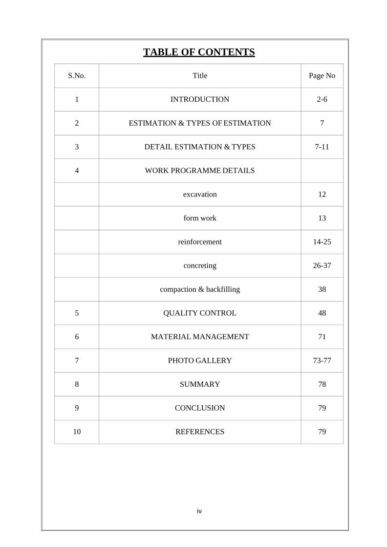
TABLE OF CONTENTS
S.No.
Title
Page No
1
INTRODUCTION
2-6
2
ESTIMATION & TYPES OF ESTIMATION
7
3
DETAIL ESTIMATION & TYPES
7-11
4 WORK PROGRAMME DETAILS
excavation 12
form work
13
reinforcement
14-25
concreting
26-37
compaction & backfilling
38
5 QUALITY CONTROL 48
6 MATERIAL MANAGEMENT 71
7
PHOTO GALLERY
73-77
8
SUMMARY
78
9
CONCLUSION
79
10
REFERENCES
79
ABSTRACT
An estimate is a computation of the quantities required and expenditure likely to be incurred
the construction of a work. In any construction project, the probable cost of construction
which is known beforehand is known as the estimated cost. And hence it is quite essential for
the arrangement of financial resources for the completion of any construction project.
In this project, the main aim was to find out the detailed estimate of quantities of all the
structural aspect of G+3 building. The Sunway Opus Grand Neville is a result of a joint
venture between Sunway City of Malaysia and Opus of Hyderabad, India.
It also aims in finding out the probable cost, or the estimated cost of the project based on the
computation of these quantities.
The structural aspects considered for the estimation of quantities are earthwork in excavation
and backfilling, concrete work in foundation and in R.C.C structures such as beams,
columns, slabs, staircases etc., steel reinforcement in beams, columns and other R.C.C
structures and brickwork in superstructure.
The computation of quantities was carried out based on the drawings of various structural
elements, such as the each floor plan, footings and columns layout, beams layout, staircases
layout, footing specifications and column specifications, which have also been provided in
this document.
These details provide an idea for requirement of quantities for a particular project and also
the likely expenditure which would be needed to be arranged .This documentation also
provides the abstract of the estimated cost for the structural aspects.

CHAPTER-1 INTRODUCTION
1
INTRODUCTION
The Sunway Opus Grand Neville is a result of a joint venture between Sunway City of
Malaysia and Opus of Hyderabad, India.
Sunway City is one of Malaysia‟s best-known and well-diversified conglomerates, with
interests in property development, leisure, entertainment, hospitality, conventions,
education and healthcare.
Opus is a leading consortium of builders and property developers in Hyderabad, India.
With a collective experience of over 100 years, Opus is a name that stands for solid
expertise.
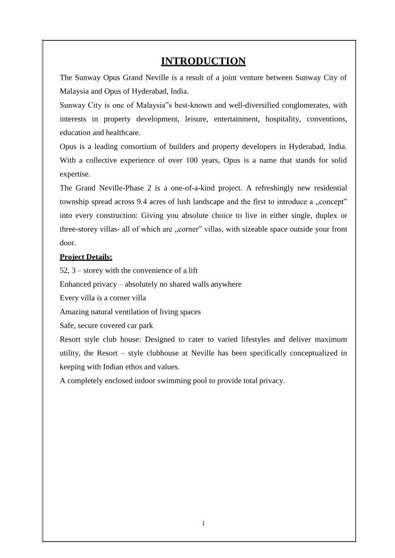
The Grand Neville-Phase 2 is a one-of-a-kind project. A refreshingly new residential
township spread across 9.4 acres of lush landscape and the first to introduce a „concept‟
into every construction: Giving you absolute choice to live in either single, duplex or
three-storey villas- all of which are „corner‟ villas, with sizeable space outside your front
door.
Project Details:
52, 3 – storey with the convenience of a lift
Enhanced privacy – absolutely no shared walls anywhere
Every villa is a corner villa
Amazing natural ventilation of living spaces
Safe, secure covered car park
Resort style club house: Designed to cater to varied lifestyles and deliver maximum
utility, the Resort – style clubhouse at Neville has been specifically conceptualized in
keeping with Indian ethos and values.
A completely enclosed indoor swimming pool to provide total privacy.
2
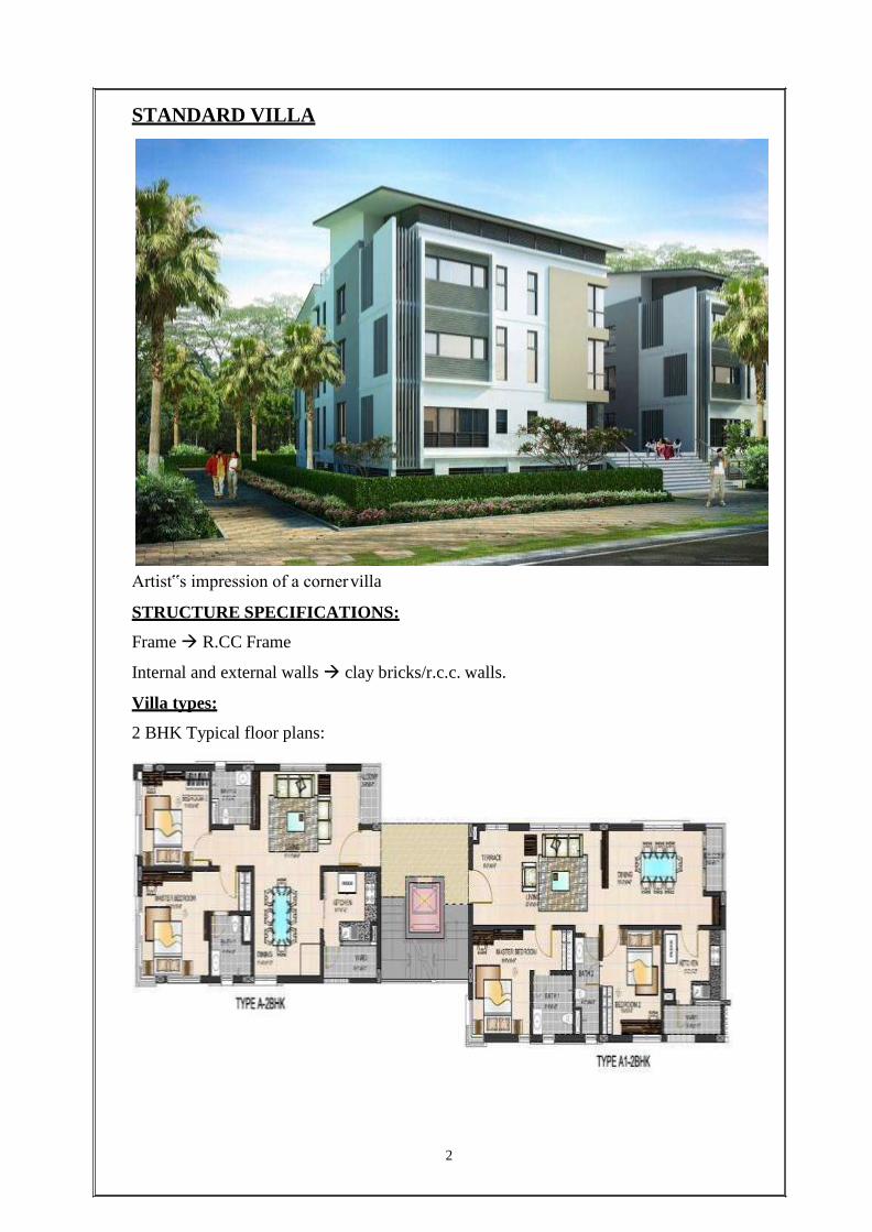
STANDARD VILLA
Artist‟s impression of a corner villa
STRUCTURE SPECIFICATIONS:
Frame R.CC Frame
Internal and external walls clay bricks/r.c.c. walls.
Villa types:
2 BHK Typical floor plans:
3
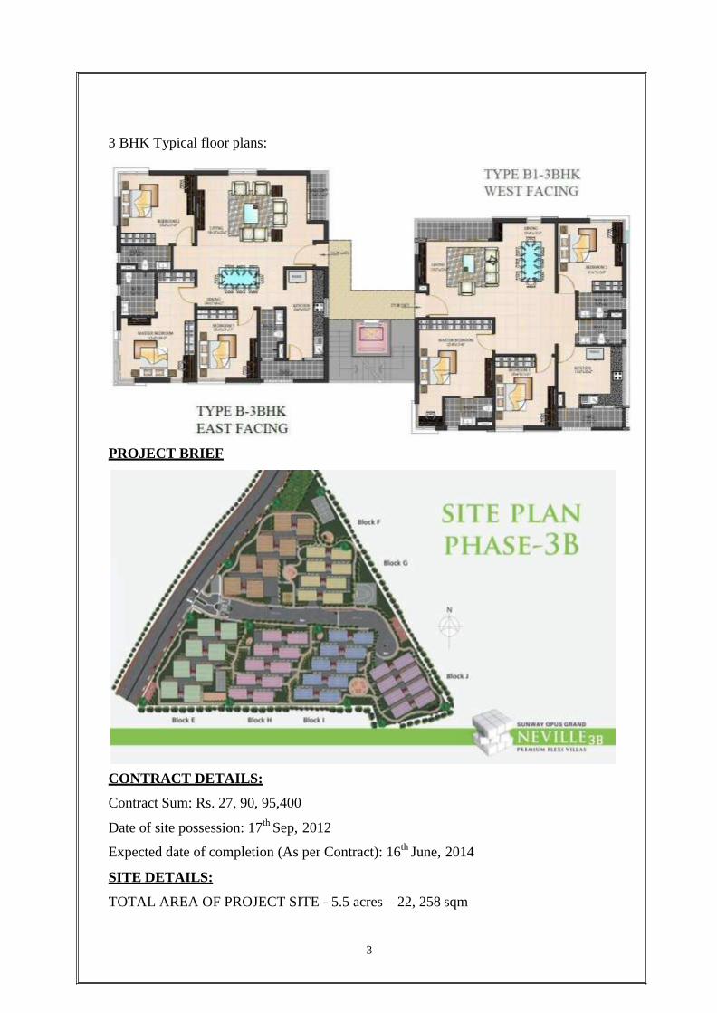
3 BHK Typical floor plans:
PROJECT BRIEF
CONTRACT DETAILS:
Contract Sum: Rs. 27, 90, 95,400
Date of site possession: 17th Sep, 2012
Expected date of completion (As per Contract): 16th June, 2014
SITE DETAILS:
TOTAL AREA OF PROJECT SITE - 5.5 acres – 22, 258 sqm
4
SEISMIC ZONE – ZONE 2
SAFE BEARING CAPACITY OF SOIL – 300 N/mm2
WORK
As an intern with GIPPL at the Sunway Opus Grand-Neville project, I was trained in the
duties of a site engineer encompassing site supervision and quality control of which the
major time was spent on site supervision. Part of my assignment was to take out
quantities of shuttering, concreting and reinforcement in order to prepare the bills. I was
majorly stationed at, but not limited to, E-Block, which was at the foundation-stage
initially as I joined and thus a logical place to start.
BLOCK DETAILS:
Plinth area of E-block = 1728 sq.m.
Control Benchmark Reduced Level = 567.85 m
Total Footings – 89
Isolated Footings – 85
Raft (lift) Footings – 4
Shorter span length = 2.425 m
E-block levels as per drawing:
Basement level = 566.5
Landscape level = 567.5
Ground floor level = 569.7
1st floor level = 573.0
2nd floor level = 576.3
Roof terrace level = 579.6
Listed below are details of various stages of construction works, as followed on site,
which I supervised along with the site engineers.

ESTIMATION
ESTIMATION
An estimate is defined, as computation or calculation of the required quantities of
finished items of work and its expenses (cost) likely to be incurred for its construction.
The main object of estimate is to know the required quantity of material, labour and cost
before actual execution .It helps an engineer to plan the construction work, for quick and
proper construction with required quality.
TYPES OF ESTIMATES:
In general, the estimate can be divided into the following three types.
They are:
Approximate estimate.
Detailed estimate.
Abstract estimate.
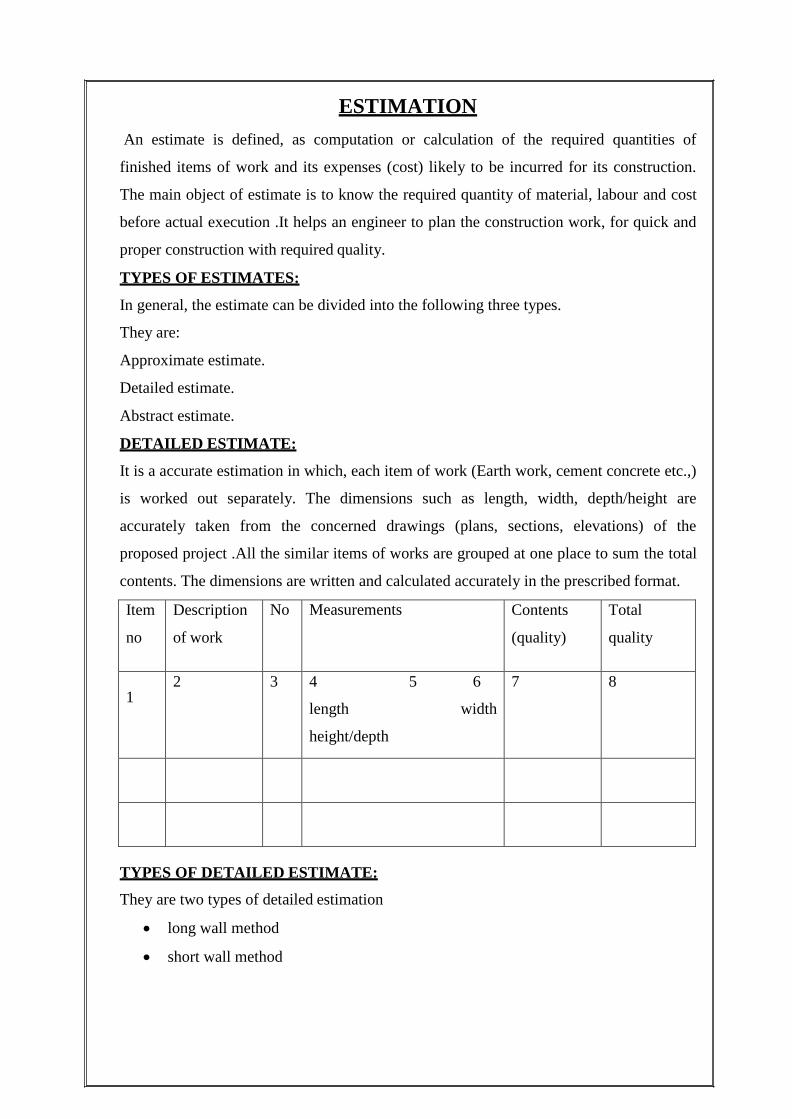
DETAILED ESTIMATE:
It is a accurate estimation in which, each item of work (Earth work, cement concrete etc.,)
is worked out separately. The dimensions such as length, width, depth/height are
accurately taken from the concerned drawings (plans, sections, elevations) of the
proposed project .All the similar items of works are grouped at one place to sum the total
contents. The dimensions are written and calculated accurately in the prescribed format.
Item
no
Description
of work
No Measurements Contents
(quality)
Total
quality
1
2 3 4 5 6
length width
height/depth
7 8
TYPES OF DETAILED ESTIMATE:
They are two types of detailed estimation
long wall method
short wall method

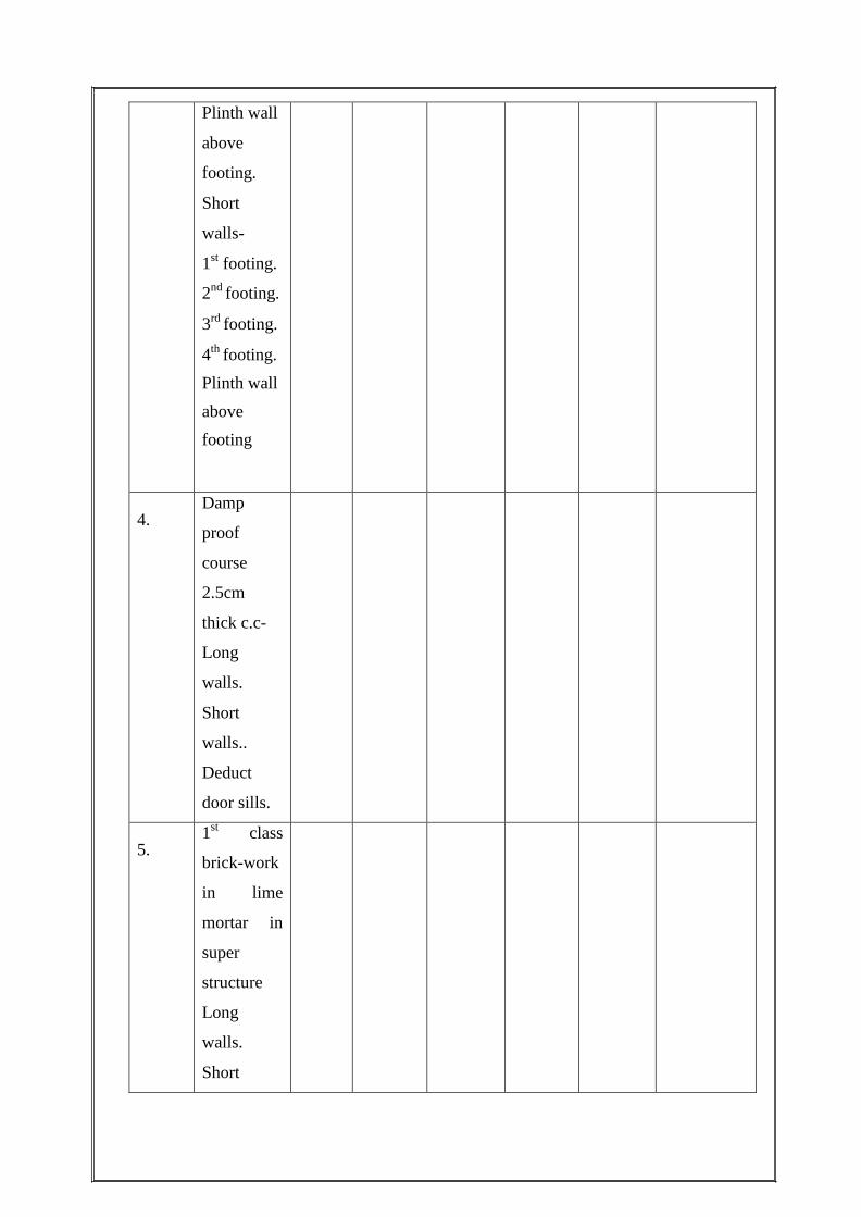
LONG WALL:
Item
no:
Particulars
of items
No. Length Breadth Height
or depth
Quantity Explanatory
note
1.
Earthwork
in
excavation
in
foundation-
Long
walls…
Short
walls…
2.
Lime
concrete in
foundation-
Long
walls..
Short
walls..
3.
1st class
brick-work
in 1:6
cement
mortar in
foundation
and plinth-
Long
walls..
1st footing..
2nd footing.
3rd footing.
4th footing.
Plinth wall
above
footing.
Short
walls-
1st footing.
2nd footing.
3rd footing.
4th footing.
Plinth wall
above
footing
4.
Damp
proof
course
2.5cm
thick c.c-
Long
walls.
Short
walls..
Deduct
door sills.
5.
1st class
brick-work
in lime
mortar in
super
structure
Long
walls.
Short

walls.
Deduct-
Door
openings
Window
Openings..
Sheleves..
Lintels
over
doors..
Lintels
over
windows.
Lintels
over
shelves..
SHORT WALLS:
Item
no:
Particulars
of items
No. Length Breadth Height
or depth
Quantity Explanatory
note
1.
Earthwork
in
excavation
in
foundation-
2.
Lime
concrete in
foundation-
3.
1st class
brick-work
in 1:6
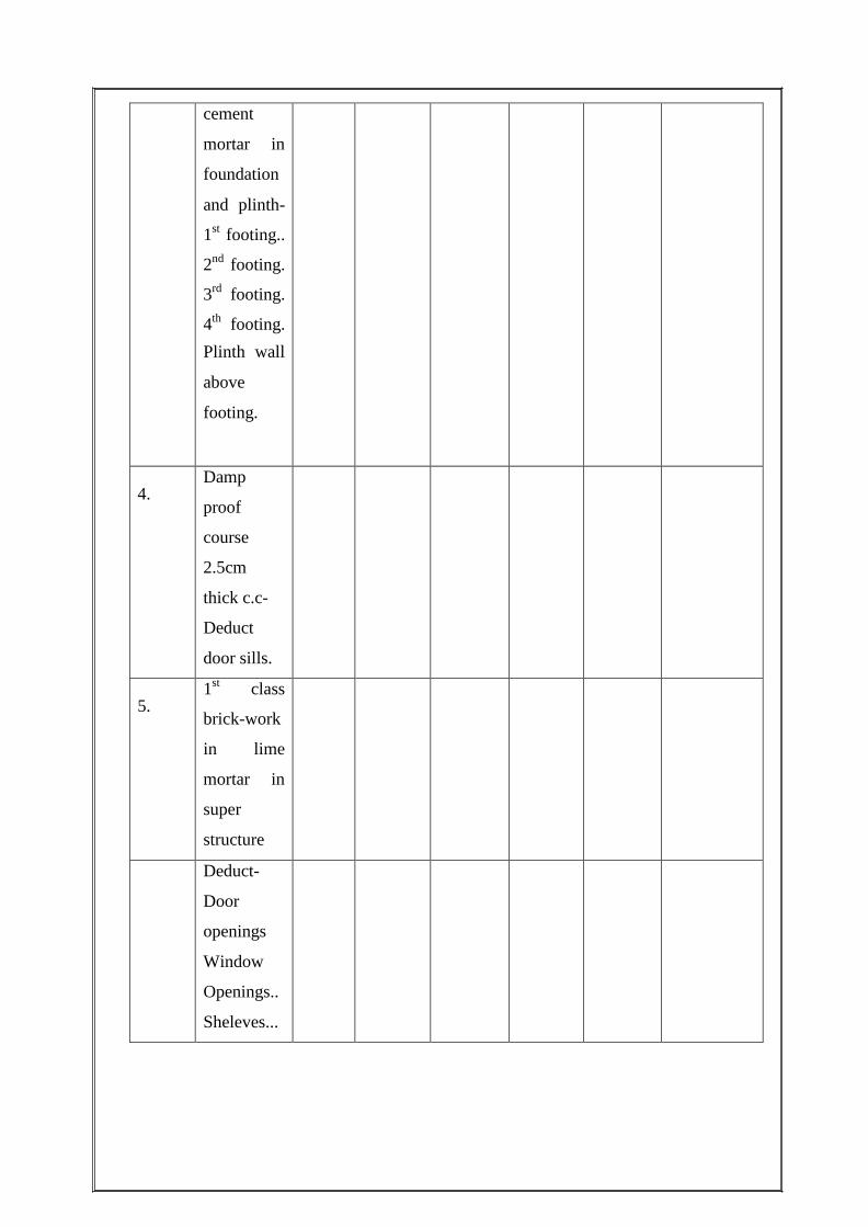
cement
mortar in
foundation
and plinth-
1st footing..
2nd footing.
3rd footing.
4th footing.
Plinth wall
above
footing.
4.
Damp
proof
course
2.5cm
thick c.c-
Deduct
door sills.
5.
1st class
brick-work
in lime
mortar in
super
structure
Deduct-
Door
openings
Window
Openings..
Sheleves...

WORK
PROGRAMME
DETAILS
WORK PROGRAMME DETAILS
EARTHWORK EXCAVATION:
Soils are the most complex of all engineering materials, and the excavation of soil is the
most hazardous of all construction occupations. Soil type is used by construction workers
to properly excavate the ground for utility and other purposes. Different methods of
construction are permitted that include sloping, shoring, shielding, and benching of the
soil for protection. We employed sloping for soil excavation here on site.
SCOPE: Covers the activity of Earthwork Excavation for foundations under floors.
MANPOWER:
Engineer – As required
Surveyor – As required
Supervisor – As required
Labour – As required
EQUIPMENT:
Total Station
Levelling instrument
Proclain
JCB Backhoe
Tippers
Compactor
METHODOLOGY:
The boundary lines will be marked with the help of total station as per co-ordinates
mentioned in drawings.
Pre levels will be taken at 5 to 15m interval (or) as directed by Engineer in charges in
both direction (x-axis & y-axis).
The levels will be plotted on plan and the same may be recorded in field books. It will be
signed by both contractor and engineer.
Excavation will be done by mechanical means (i.e. proclaim and tippers)
Excavated earth will be disposed in location as directed by engineer in charge.
The location of blocks will be once again verified with the help of total station after
completion of excavation to start the next activity.
If there is any minor variation, it will be dressed by manual means.

11
FORMWORK:
SCOPE: Covers the activity of formwork for foundations, plinth beam, columns and
slab.
MANPOWER:
Engineer – As required
Surveyor – As required
Supervisor – As required
Labour – As required
EQUIPMENT:
Shuttering Plates
Adjustable Props
METHODOLOGY:
Formwork for footings, plinth beam, columns, beams and slabs for shuttering will
be M.S. Plates (Fabricated with M.S. Sheet and M.S. Angles)
The shutters shall be made free from dirt and dead mortar.
Appropriate shutter releasing oil shall be applied all over the shutter.
All the joints of the shutters are pasted with 3mm foam to avoid slurry leakage.
Adequate support is provided to formwork to maintain the alignment, verticality at
the time of concrete.
Alignment, verticality of formwork shall be checked.
All dimensions and levels of the formwork shall be as per the drawings.
For facilitating concreting and for inspection, a staging with working platform
shall be provided.
To check the verticality, a plumb bob weighing 1kg tied to a binding wire shall be
made to fall from top.
To avoid slurry leakage, 3mm foam shall be pasted on the face of the shutters as
well as on all the joints of the shutters.
12
REINFORCEMENT:
SCOPE: Covers the activity of reinforcement for foundations, columns, plinth beams and
slabs.
MANPOWER:
Engineer – As required
Surveyor – As required
Supervisor – As required
Labour – As required
EQUIPMENT:
Rod cutting machine
Rod bending machine
METHODOLOGY:
After receiving G.F.C (Good for Construction) drawings from the client, B.B.S
may be prepared as per drawings and it should be submitted to client.
After getting required approval from the client, cutting, bending, and tying of
reinforcement steel will be done as per approved B.B.S & drawings.
Bar bending and cutting machines shall be used for bending and cutting of steel.
All laps in reinforcement shall be in accordance with the drawings and shall be
provided in the “Lap Zone” as indicated in the drawings.
Bars shall be firmly fixed using 18 gauges annealed steel binding wire.
Binding wires shall be bent inwards and loose ends out, so that they do not
protrude out of concrete.
Clear cover of 15mm to 50mm to all outer reinforcement shall be maintained or as
shown in drawings.
13
PREPERATION OF BBS AND REORD OF CONSUMPTION:
Prepare bar bending schedule from approved, latest revised drawings and check
for error/inconsistencies and take approval from consultant/client.
Plan and check for fix ability and sequence of fixing.
Plan intelligent cutting from full length bars by preparing cutting length.
Cutting length shall be worked out after considering bend effect.
Check the bent shapes for dimensional accuracy against full scale template and get
approval from client.
Keep painted specimen bars for comparison with production.
Use cut pieces for ancillary works and record consumption.
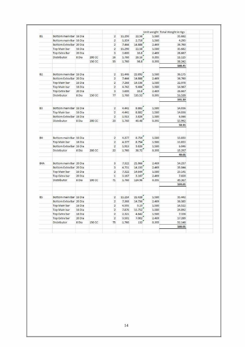
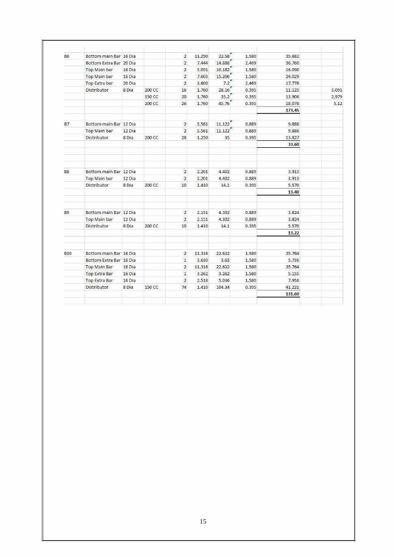
GROUND FLOOR QUANTITES:
14
15
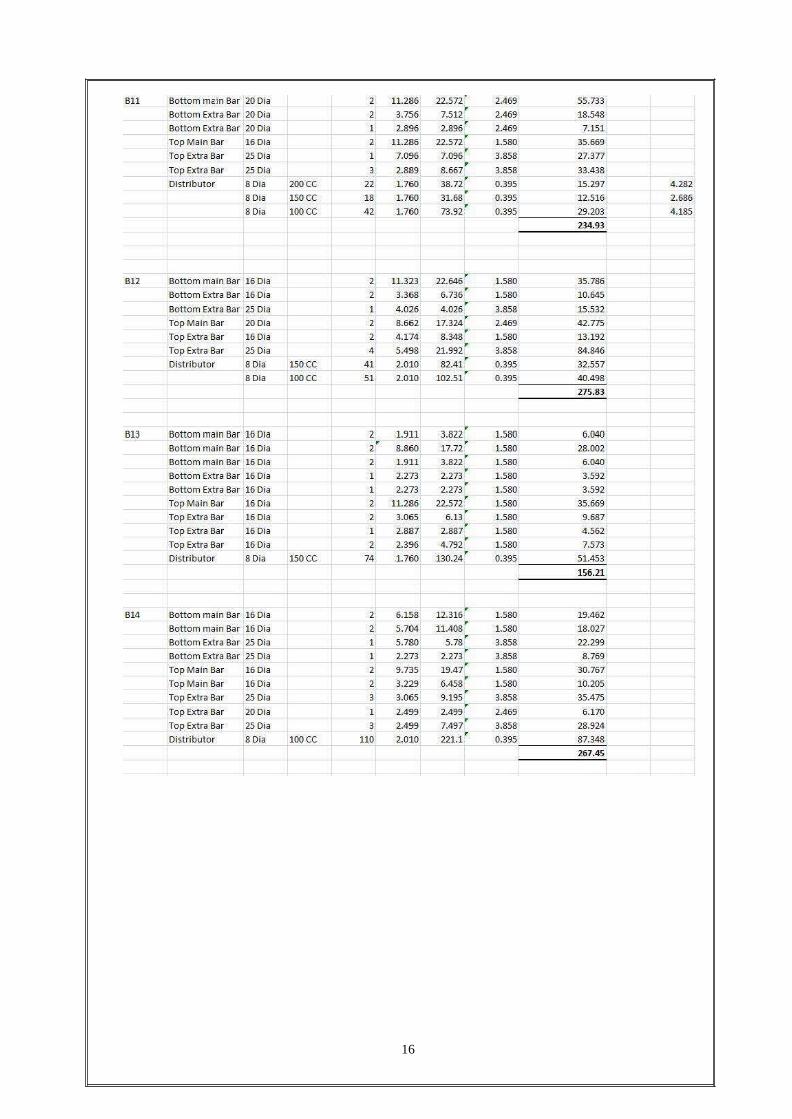
16
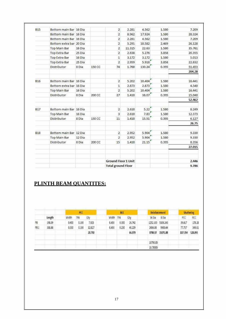
17
PLINTH BEAM QUANTITES:
18
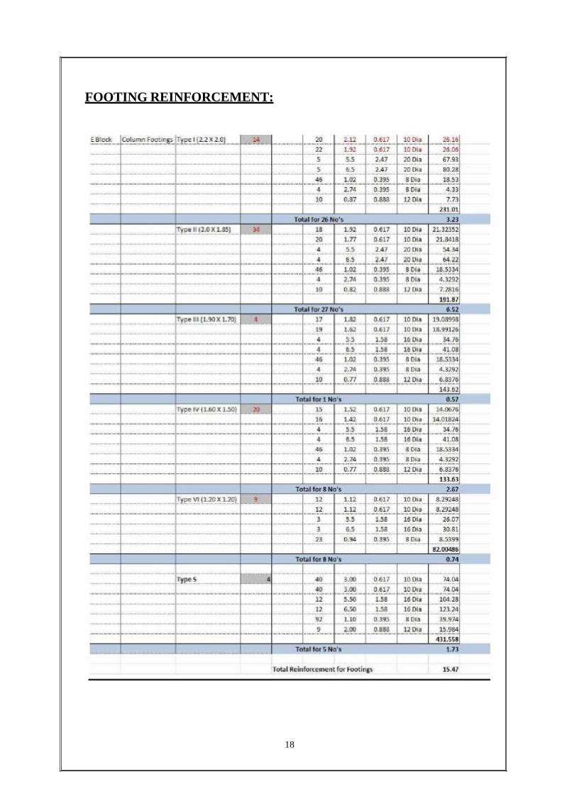
FOOTING REINFORCEMENT:
19
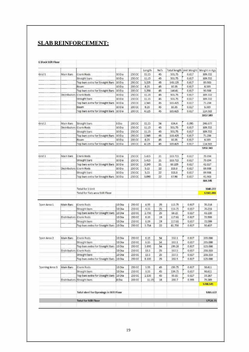
SLAB REINFORCEMENT:
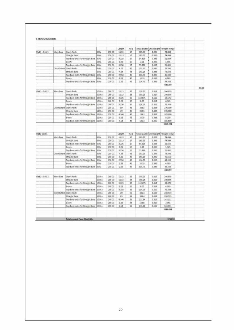
20
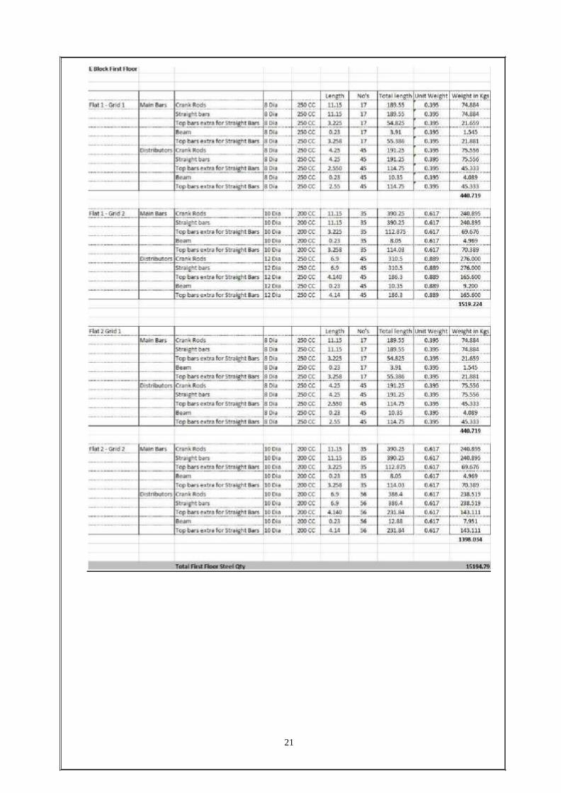
21
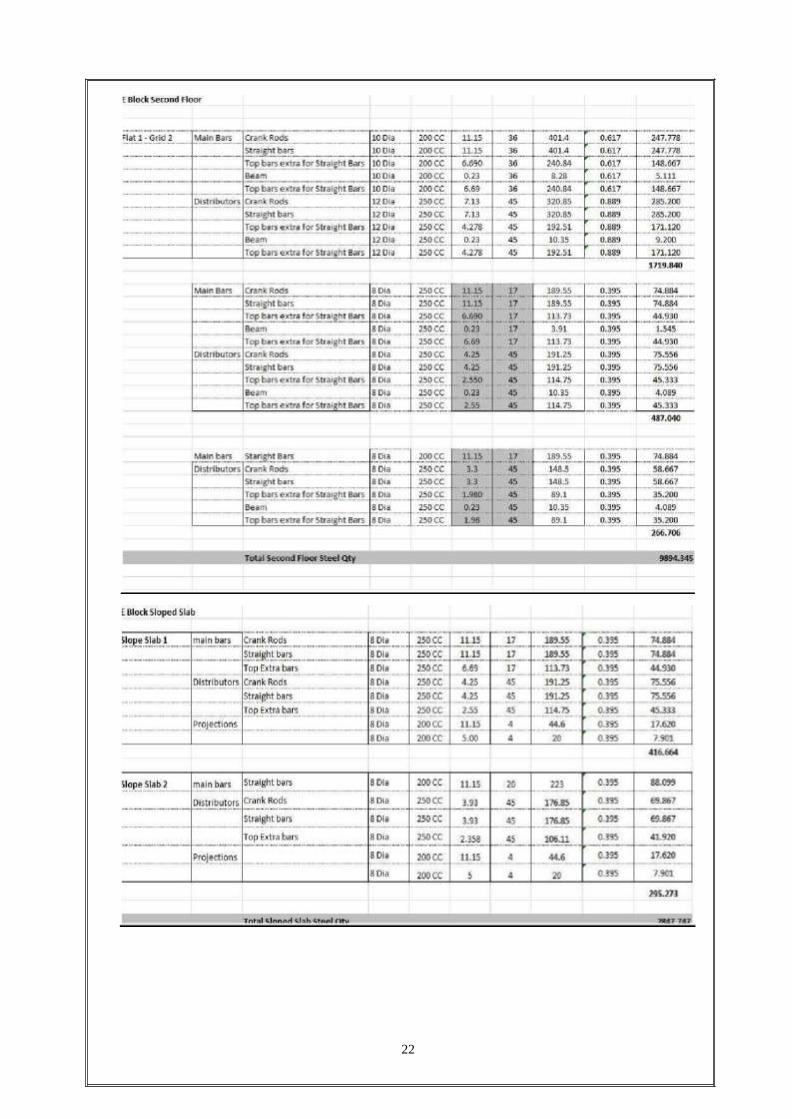
22

23
FIXING OF REINFORCEMENT:
Avoid substitution of bars, if unavoidable check for over consumption.
Do not use tack weld at cross points.
Avoid excessive chairs. Arrive at optimum spacing of chairs by trials.
Use cut pieces/welded scraps for chairs. Avoid using full length bars for making
chairs.
Use spider beam to lift heavy cages.
Check spacing's, number of bars, location of bars etc. before start of concrete.
Fix the bars accurately with specified cover of size and grade.
Plan best fixing sequence to achieve accuracy and to accommodate form work,
void formers, starter bars etc.
Ensure inspection of reinforcement fixing intermittently to avoid redoing.
Avoid large time gap between the concrete pours to prevent deterioration of
projected reinforcement.
24
CONCRETING:
SCOPE: Covers the activity of concreting for foundations, plinth beams, columns and
slabs.
MANPOWER:
Engineer – As required
Surveyor - 1
Supervisor – As required
Labour – As required
EQUIPMENT:
Concrete vibrators
METHODOLOGY:
During concreting:
Before concreting commences, proper access and working platform for workers
involved in placing, compacting and finishing shall be ensured.
40mm immersion type needle vibrator shall be used for compaction of concrete.
Effective distances between the reinforcement shall not be disturbed while
concreting.
Corrective action shall be immediately taken in case of loosening of supports and
fixings due to vibrations transmitted to the formwork.
Concrete shall be laid up to the required levels as per drawing (GFC)
After Concreting:
Once the concreting is complete, the verticality shall be checked.
If any deviations are found, then the supports shall be adjusted and shall be
straightened.
De-shuttering:
After 12-24 hrs. of casting the concrete, de-shuttering shall be done by loosening
the nut bolts. The frames shall be smoothly struck, so that the concrete edges are
not damaged.
All the ties, supporting arrangements should be loosened and removed gradually.
Use of crowbars to open the forms shall be avoided at all costs.
On removal of frames, the formwork shall be carefully lowered and not dropped
and damaged.
Panel faces shall be carefully removed and lowered.
25
Formwork as soon as removed shall be cleaned with a stiff brush and immediately
lowered and stacked neatly over the ground at the allotted area.
Dust, dirt shall be removed.
Damaged formwork shall be sorted out and immediately repaired before re-use.
Loose mailing, soldiers etc shall be stored with respective panels after numbering
for proper match when re-used.
Bolts, nuts, clamps and ties shall be stored in separate bins and boxes.
CURING:
Quality of water: Rain water, fresh water and bore water can be used. However,
salty/sea water cannot be used.
Curing shall be commenced on immediate removal of formwork.
Curing shall be done by applying wet jute bags, sprinkling.
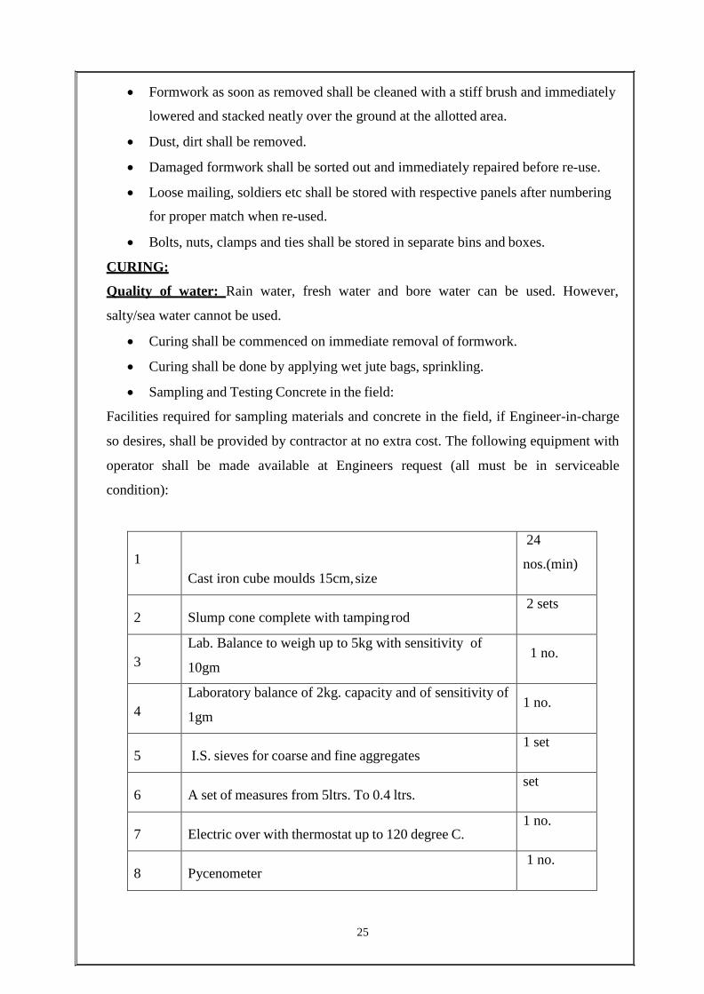
Sampling and Testing Concrete in the field:
Facilities required for sampling materials and concrete in the field, if Engineer-in-charge
so desires, shall be provided by contractor at no extra cost. The following equipment with
operator shall be made available at Engineers request (all must be in serviceable
condition):
1
Cast iron cube moulds 15cm, size
24
nos.(min)
2
Slump cone complete with tamping rod
2 sets
3
Lab. Balance to weigh up to 5kg with sensitivity of
10gm 1 no.
4
Laboratory balance of 2kg. capacity and of sensitivity of
1gm 1 no.
5
I.S. sieves for coarse and fine aggregates
1 set
6
A set of measures from 5ltrs. To 0.4 ltrs.
set
7
Electric over with thermostat up to 120 degree C.
1 no.
8
Pycenometer
1 no.

26
9
Calibrated glass jar 1 litre capacity
2 nos.
10
Glass flasks and metal containers
As required
11
Concrete cube testing machine
1 no.
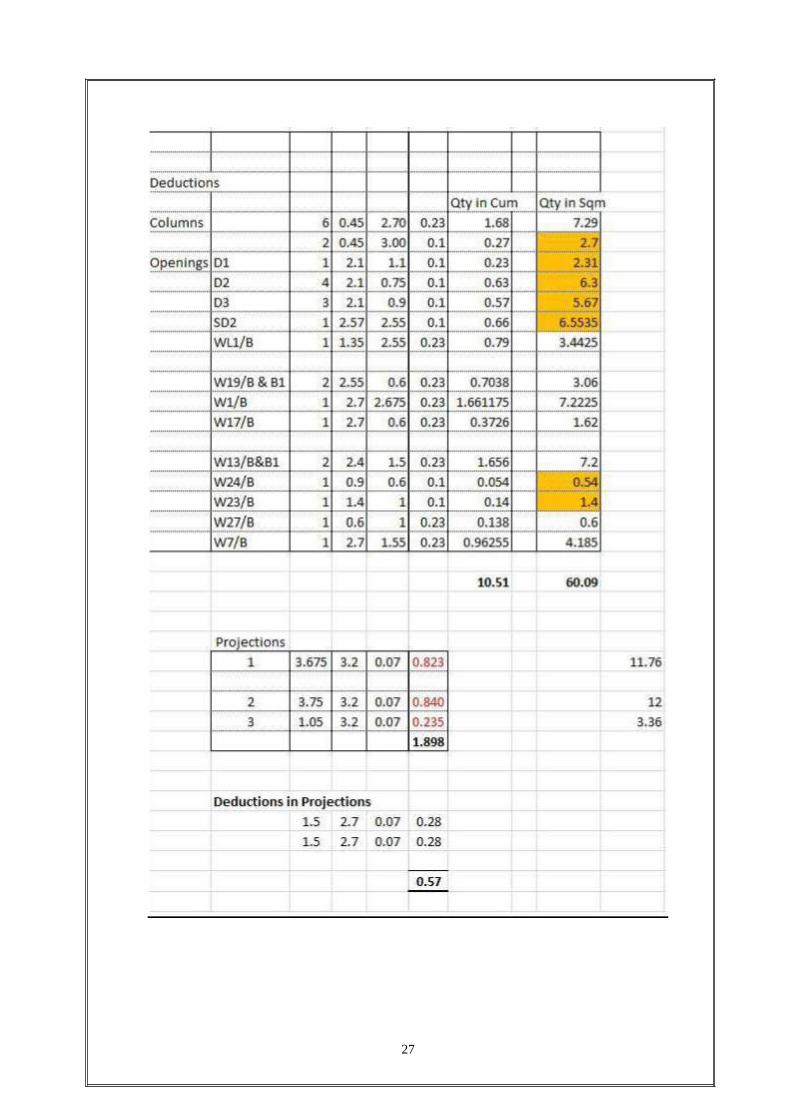
BRICK WORK:
27

28
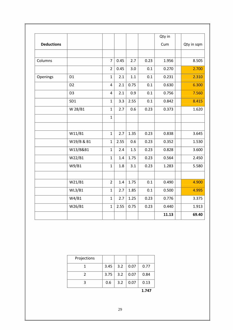
29
Deductions
Qty in
Cum
Qty in sqm
Columns 7 0.45 2.7 0.23 1.956 8.505
2 0.45 3.0 0.1 0.270 2.700
Openings D1 1 2.1 1.1 0.1 0.231 2.310
D2 4 2.1 0.75 0.1 0.630 6.300
D3 4 2.1 0.9 0.1 0.756 7.560
SD1 1 3.3 2.55 0.1 0.842 8.415
W 28/B1 1 2.7 0.6 0.23 0.373 1.620
1
W11/B1 1 2.7 1.35 0.23 0.838 3.645
W19/B & B1 1 2.55 0.6 0.23 0.352 1.530
W13/B&B1 1 2.4 1.5 0.23 0.828 3.600
W22/B1 1 1.4 1.75 0.23 0.564 2.450
W9/B1 1 1.8 3.1 0.23 1.283 5.580
W21/B1 2 1.4 1.75 0.1 0.490 4.900
WL3/B1 1 2.7 1.85 0.1 0.500 4.995
W4/B1 1 2.7 1.25 0.23 0.776 3.375
W26/B1 1 2.55 0.75 0.23 0.440 1.913
11.13 69.40
Projections
1 3.45 3.2 0.07 0.77
2 3.75 3.2 0.07 0.84
3 0.6 3.2 0.07 0.13
1.747
30
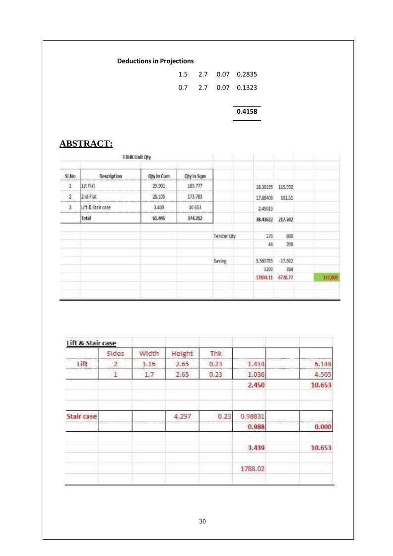
Deductions in Projections
1.5 2.7 0.07 0.2835
0.7 2.7 0.07 0.1323
0.4158
ABSTRACT:

31
PLASTERING QUANTITES:
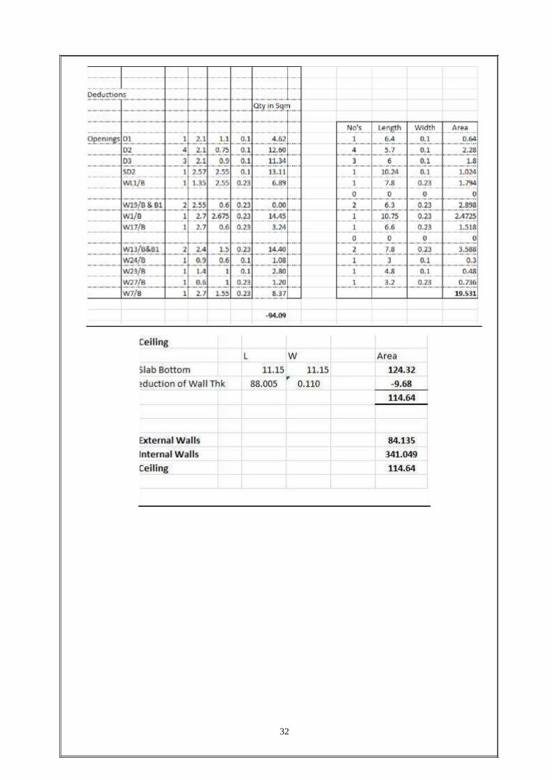
32

33
ABSTRACT:
34
BACKFILLING:
SCOPE: Covers the activity of quarry dust filling, earth filling in the trenches of
foundations, plinth, under floors in all towers.
MANPOWER:
Engineer: As required
Supervisor: As required
Labour: As required
EQUIPMENT:
1MT mechanical vibratory compactor (Diesel Operated)
Levelling instrument
Rapid moisture meter
Field density core cutter with dolly and hammer
Types of backfilling:
Dry fills
Cement rock fills
Hydraulic sand fill
Paste back fill
Dry fills:
Generally consists of surface sand, gravel, open pit waste rock, underground waste rock,
smelter slag generally unclassified except to remove large boulders usually transported
underground by dropping down a raise from surface directly into a slope or to a level
where it is hauled to a slope with an LHD or trucks.
Usually contains some adsorbed surface moisture.
Suitable for mechanized cut and fill or Avoca or other method where structural backfill is
not required.
Cement rock fills:
Generally consist of waste rock mixed with cement slurry to improve the bond strength
between the rock fragments. Methods of placement involve mixing the rock and cement
slurry in a hopper before placing in slopes, or percolating slurry over the rock after it has
been placed.
The waste rock can be classified or unclassified.
CRF contains a mixture of coarse aggregate (<150 mm) and fine aggregate (<10 mm
fraction). The ideal gradation is one which minimizes the void space.

Cement slurry concentration is approximately 55% by wt. (1.2:1 water: cement ratio)
Suitable for long hole open sloping, undercut and fill, and other methods where a
structural fill is required.
Hydraulic sand fill:
Hydraulic sandfill can consist either of classified mill tailings (Westmin-Myra Falls) or
naturally occurring sand deposits mined on surface (Detour Lake Mine). Hydraulic
sandfill is prepared by dewatering the mill tailings stream to a pulp density of
approximately 65-70% solids (depending on S.G) and then passing it through hydro
cyclones to remove the "slimes" and retain the sand fraction for backfill. Slimes are
removed to improve the percolation rate of the backfill. The backfill mixture is
hydraulically pumped from surface through a network of pipes and boreholes to the slope.
Sand obtained from surface borrow pits will be screened prior to use in a backfill plant to
remove oversize particles that could plug the backfill line.
Sandfill can be cemented or uncemented.
Paste Backfill:
Paste backfill is a high density backfill (>70% solids depending on SG).
In order to pump material at this density, a component of fines is required.
As a general rule, the fines content (<20 micron) should be a minimum of 15% by
weight
The slump of paste backfills is approximately in the 7-10 inch range
Paste backfill is pumped by piston type pumps of the same type used to pump
concrete.
Whole mill tailings can often be used to make paste backfill. The final product has
a lower void ratio so the backfill is denser.
Many mines are moving towards paste backfill because it a lower cement content
is required to gain equivalent strengths when compared to conventional hydraulic
fill.
METHODOLOGY:
The earth used for filling should be free from all roots, grass, shrubs, vegetation,
rubbish etc.
The top soil containing salts/sulphates and other foreign materials shall be
removed. The materials so removed shall be burnt or disposed off.
All lumps & cods exceeding 150mm, in any direction should be broken.
35
36
All backfilling shall be done in layers (as specified below). For site grading
filling, work layer thickness can be up to 200mm.
Each layer is to be properly spread, watered & compacted. Thickness of each
subsequent layer and rammer/compactors shall be as mentioned above.
The backfilled layers shall be well consolidated by means of rammers to atleast
90% of the standard density at OMC.
Care shall be taken while ramming near walls, columns & plinth beam sides. The
layers shall be laid at 150mm thickness.
When backfilling reaches the finished level, the surface shall be flooded with
water and allow for atleast 24 hours drying. Then the surface shall be again
compacted as specified above to avoid settlement at a later stage.
Ensure that the consolidated top layer is dressed to required slope & level.
BACKFILLING – LOCATION WISE:
To the extent available, selected surplus soils from excavated materials shall be used as
backfill. Fill material shall be free from clods, salts, sulphates and organic or other
foreign materials. All clods of earth shall be broken or removed. Where excavated
material is mostly rock, the boulders shall be broken in to pieces of size not more than
150mm, mixed with properly graded fine material consisting of murram or earth to fill up
the voids and the mixture used for the filling.
BACKFILLING IN PITS AND TRENCHES AROUND FOUNDATIONS OF
STRUCTURES, WALLS etc.
As soon as the work in foundations has been inspected and measured, the spaces around
the foundations, structures, pits, trenches, etc., shall be cleared of all debris and filled with
approved layers not exceeding as specified, each layer shall be watered, rammed and
properly consolidated, before succeeding layer is laid. Each layer is consolidated to
achieve 90% standard proctor density as specified in the Civil Technical specifications,
the compaction shall be done as far as possible by the mechanical compactors. The final
backfill surface shall be trimmed and levelled to proper profile as indicated in drawings.
BACKFILLING IN PLINTH
Plinth filling shall be carried out with approved material as described herein before in
layers, watered and compacted with mechanical compactors. Client may however permit
manual compaction by hand tampers in case he is satisfied that mechanical compaction is
not possible. When filling reaches finished level, the surface shall be flooded with water,
37
unless otherwise directed, for at least 24 hours allow drying and then the surface again
compacted as specified above to avoid settlements at a later stage.
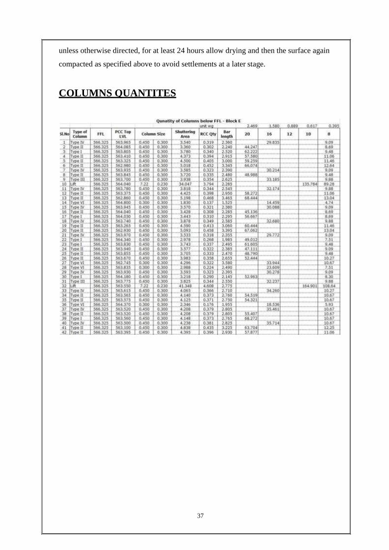
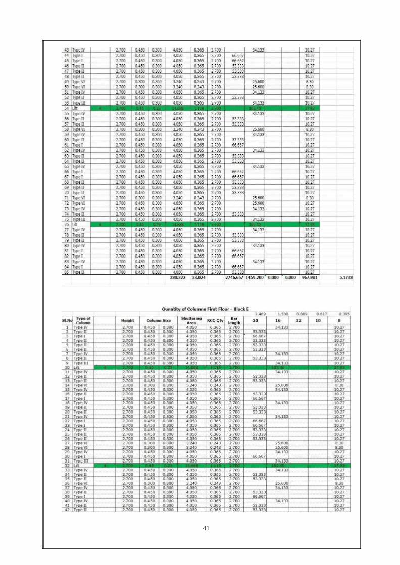
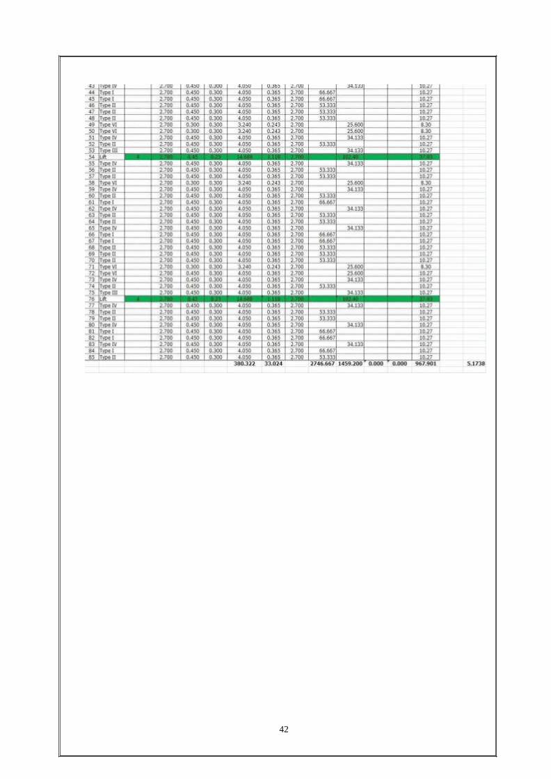
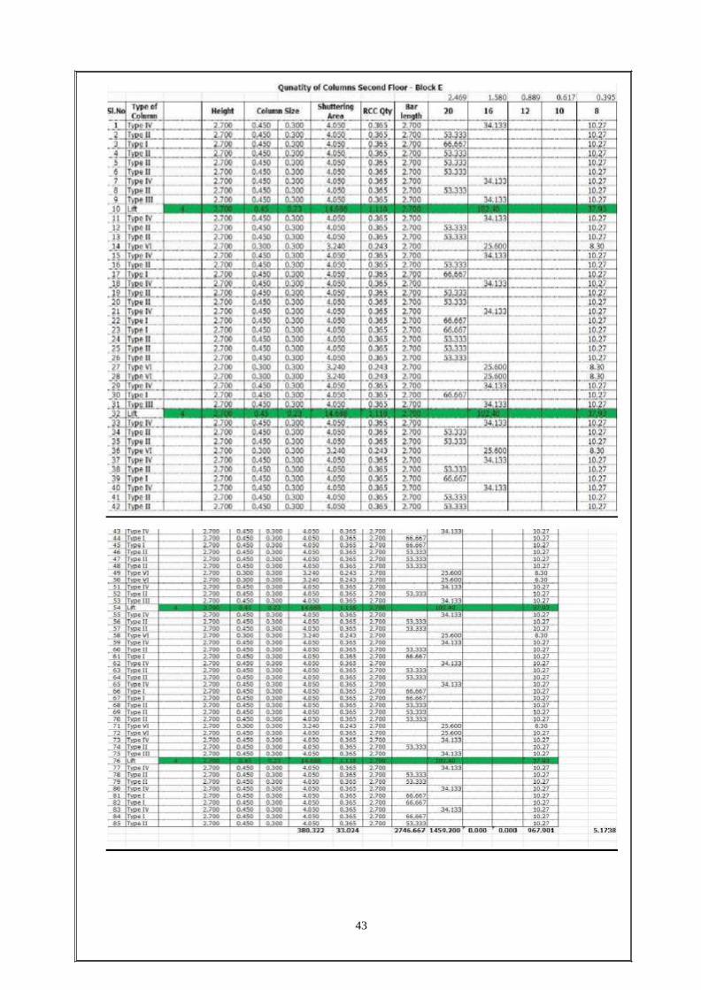
COLUMNS QUANTITES
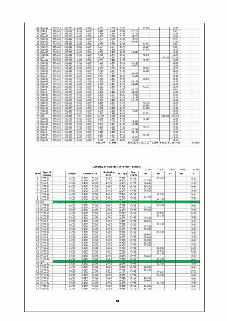
38

39

40
41
42
43

QUALITY CONTROL
44
QUALITY CONTROL
Following the compaction, in-situ density test (core-cutter test), moisture content, the
MDD test & OMC test are carried out at the site laboratory as per testing frequency plan.
Density-moisture relationship as per IS 2720 (Part8) shall be carried out at the site
laboratory as per testing frequency plan.
Each 100sqm. area compacted in layers shall be tested {as per IS2720 (Part29) and
records for the same shall be maintained} for each layer in plinth filling before starting
placing soil for the next layer.
ANTI TERMITE TREATMENT
SCOPE: Covers the activity of pre-constructional anti-termite treatment for the soil‟s
with approved chemicals in water emulsion in foundation trenches for columns, plinth
beams, plinth filling, at junction of walls and floor, in expansion of joints etc., Unless
otherwise stipulated, the anti-termite treatment shall be carried out as per IS 6313(Part 2).
MATERIALS:
Chloropyripos 20EC Emulsifiable concentrate (IS 8944-1974) or equivalent material
Water
METHODOLOGY OF WORKS:
SITE PREPARATION: To ensure uniform distribution of the chemical emulsion and to
assist penetration, the following site preparation shall be carried out:
All trees, stumps, logs or roots from the building site shall be removed.
All concrete form work (if left anywhere), levelling pegs, timber off-cuts and
other building debris from the area to be treated, shall be removed.
If the sandy or porous soil to be treated, preliminary moistening shall be done to
fill capillary spaces in soil in order to prevent the loss of emulsion through piping
or excessive percolations.
If foundations are water logged, the water shall be pumped out before application
of chemical emulsion and it shall be applied only when the soil is absorbent.
If clays and other heavy soils where penetration is likely to be slow and on sloping
site, where run-off to the treating solution is likely to occur, the surface of the soil
shall be scarified to a depth of 75mm atleast.
All sub-floor levelling and grading shall be completed. All cutting trenches and
excavations shall be completed with backfilling in place, borrowed fill must be
free from organic debris and shall be well compacted.
45
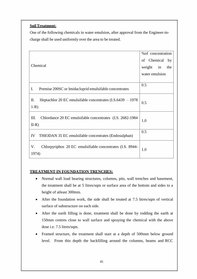
Soil Treatment:
One of the following chemicals in water emulsion, after approval from the Engineer-in-
charge shall be used uniformly over the area to be treated.
Chemical
%of concentration
of Chemical by
weight in the
water emulsion
I. Premise 200SC or Imidacloprid emulsifable concentrates
0.5
II. Heptachlor 20 EC emulsifable concentrates (I.S.6439 – 1978
1-R)
0.5
III. Chlordance 20 EC emulsifable concentrates (I.S. 2682-1984
II-R)
1.0
IV THIODAN 35 EC emulsifable concentrates (Endosulphan)
0.5
V. Chlorpyriphos 20 EC emulsifiable concentrates (I.S. 8944-
1974)
1.0
TREATMENT IN FOUNDATION TRENCHES:
Normal wall load bearing structures, columns, pits, wall trenches and basement,
the treatment shall be at 5 litres/sqm or surface area of the bottom and sides to a
height of atleast 300mm.
After the foundation work, the side shall be treated at 7.5 litres/sqm of vertical
surface of substructure on each side.
After the earth filling is done, treatment shall be done by rodding the earth at
150mm centres close to wall surface and spraying the chemical with the above
dose i.e. 7.5 litres/sqm.
Framed structure, the treatment shall start at a depth of 500mm below ground
level. From this depth the backfilling around the columns, beams and RCC
46
basement walls shall be treated at 7.5 litres/sqm of the vertical and at 5 litres/sqm
for the horizontal surface at the bottom in the trenches / pits.
TREATMENT ON TOP SURFACES ON PLINTH FILLINGS:
The top surface of the filled earth within plinth walls hall be treated with chemical
emulsion at the rate of 5 litres/sqm of the surface area before sub-base to floor is laid. If
filled earth has been well rammed and the surface does not allow the emulsion to seep
through, holes upto 50 to 75mm deep at 150mm centres both ways shall be made with
crow bars on the surface to facilitate saturation of the soil with the emulsion.
TREATMENT AT JUNCTION OF WALLS AND FLOORS:
Special care shall be taken to establish continuity of the vertical chemical barrier
on the inner wall surfaces from the finished ground level (or from level where the
treatment had stopped) up to the level of the filled earth surface.
To achieve this a small channel 30 x 30 mm, shall be made at all the junctions of
wall/column with floor (before laying subgrade) and rod holes made in the
channel up to the finished ground level at 150mm apart and the iron rod moved
backward and forward to break the earth and chemical emulsion poured along the
channel at 7.5 litres/sqm of the vertical wall/ column surfaces so as to soak the soil
right up to the bottom.
The soil shall be tamped back into place after this operation
TREATMENT FOR EXPANSION JOINTS:
The soil beneath the expansion joints shall receive special attention when the treatment
above is in progress. This treatment shall be supplemented by treating through the
expansion joint after sub-grade has been laid at the rate of 2litres/m length of expansion
joint.
PRECAUTIONS DURING TREATMENT:
Utmost care shall be taken to see that the chemical barrier is complete and
continuous. Each part of the area shall receive the prescribed dosage of chemical
emulsion.
The treatment shall not be carried out when it is raining or when the soil is wet
with rain or sub-soil water.
Once formed, the treated soil barrier shall not be disturbed. If by chance, treated
soil barriers are disturbed, immediate steps shall be taken to restore the continuity
and completeness of the barrier system.
PRECAUTIONS FOR HEALTH HAZARDS AND SAFETY MEASURES:
All the chemicals mentioned above are poisonous and hazardous to health. These
chemicals can have an adverse effect upon health when absorbed through the skin,
inhaled as vapours or spray mist or swallowed.
Brick work quantities:
PLASTERING:
SCOPE: Covers the activity of 20mm thick external cement plastering on masonry or
concrete surface for the project.
METHODOLOGY:
MATERIALS:
Cement
Sand
Water
Integral water-proofing compound
MATERIAL LOGISTICS:
For all towers, mechanical winches shall be provided at such a location that is easily
accessible for manual loading of cement bags and sand etc.
TOOLS AND MACHINARIES:
Mixer machine/hand mixing as the case may be,
Measurement boxes, trowels, plumb bob, straight edges, right angles, nylon
thread, measuring tape, sieve, spades, mortar pan, mortar tray etc.
PREPARATION:
Material used for plastering viz cement, sand and water shall be inspected and
tested prior to their incorporation into the works. Sand shall be sieved prior to use.
Check the silt content of the sand which should not exceed more than 8 %. In case
the silt content is more than 8%, then it should be washed thoroughly before use.
Steel scaffolding with necessary safety arrangements shall be erected to carry out
works at height. Erected scaffolding shall be checked and approved by SPCL
construction safety engineer prior to its use.
All doors, window frames to be checked for line, level, plumb and holdfasts
before starting the plastering work. Check if all the holdfasts are fixed properly for
door frames. Opening shall be checked with approved templates for dimensions.
47
Loose mortar or dust sticking to masonry walls shall be removed by brushing.
Concrete surfaces shall be cleaned and hacked with hacking machine to get proper
bonding. Chicken mesh shall be provided at the junction of masonry and RCC for
proper bonding, with an overlap of 15cm.
Surface to receive plaster should be made sufficiently wet on previous day of
plastering.
Tie rod holes in concrete members to be grouted prior to plastering work.
All related MEP work shall be completed prior to starting of plastering. Electrical
conduits, junction boxes and plumbing pipes shall be fixed in place properly.
Ensure proper hacking with machine over the concrete surfaces for proper
bonding.
Check for dimensions, rectangularity and verticality of the room to receive plaster.
Put the bull marks of appropriate thickness on the surface to receive plastering.
MESH TO WALLS:
Approved mesh will be laid single layer of GI expanded metal mesh of 0.35 mm nominal
thickness and 125mm width shall be provided at the junctions of the masonry and
concrete members and also over the electrical conduits exceeding more than two numbers
together. The lap should be equal on either sides of the junction, properly stretched and
nailed measuring equal thickness/width on plaster on both sides of the mesh.
Use of mesh walls:
Meshes are often used to screen out unwanted things, such as insects. Wire
screens on windows and mosquito netting can be considered as types of meshes.
Wire screens can be used to shield against radio frequency radiation, e.g.
in microwave ovens and Faraday cages.
Metal and nylon wire mesh filters are used in filtration
Wire mesh is used in guarding for secure areas and as protection in the form
of vandal screens.
Wire mesh can be fabricated to produce park benches, waste baskets and other
baskets for material handling.
Woven meshes are basic to screen printing.
Surgical mesh is used to provide a reinforcing structure in surgical procedures like
inguinal hernioplasty, and umbilical hernia repair.
Meshes are also used as drum heads in practice and electronic drum sets.
48
Human animal trapping now use woven or welded wire mesh cages to trap wild
animals in domestic areas, such as raccoon's, skunks, etc.
APPLICATION PROCEDURE:
Mortar mixing: 20mm thick cement plastering on external surface of masonry or concrete
surface shall be done in two layers.
First coat:
One portion of cement shall be mixed with five portions of screened, clean, fine
sand as approved, by volume (1:5) and mixed till uniform colour is formed.
And add water proofing compound to the water as per the manufacturer‟s
instructions and mix well till the required consistency is achieved. Mixture shall
be made in small quantities as required and applied within 15 min of mixing.
And continue plastering with a 12 mm thickness rough finish.
Final coat:
Final coat of plaster with cement mortar of 1:5 with a thickness of 8mm without
any waterproofing compound with/ smooth finish.
External plastering shall be applied from top to bottom, in that fashion.
Plastering guides using nylon threads are made to ensure uniform thickness of
plastering.
Mortar shall be applied on the surface, floated with wooden float and shall be
levelled with straight edge to the required thickness.
All the dimensions, line, level, plumb and diagonal must be checked regularly to
ensure the conformity of the on-going work as per drawings.
Dimensions of all the openings shall be checked during plastering.
Plaster shall be made rough with wire when still green to ensure proper bonding of
tiles later wherever applicable.
Necessary grooves in plastering both horizontally and vertically as per elevation
drawings shall be done in final coat of plastering.
CURING:
Each coat shall be properly cured until the next coat or for a maximum period of 7 days.
Finished plaster shall be kept for at least 10 days after completion. In hot weather, walls
exposed to high temperatures shall be screened with matting kept constantly or by
continuous curing.
49
50
TOLERANCES IN PLASTERING:
The finished plaster surface shall not show any deviation more than 2mm/metre when
checked with a straight edge placed against the surface.
QUALITY ASSURANCE AND QUALITY CONTROL AT THE SITE
General responsibilities of Quality Assurance / Quality Control Department:
Documenting Quality Assurance Plan and methodologies etc.
Reviewing work instruction and quality plan.
Carrying out inspection and testing of materials.
QA/QC Engineer shall also maintain the results obtained from inspections and
testing processes. Also he shall be responsible to maintain the documents and the
results so as to maintain traceability of materials in the final works.
QA/QC engineer shall carry out inspections of subcontractors and suppliers for
qualifying them also once the suppliers are approved they shall be subjected to
routine audits for and they shall be reviewed at regular internal. The degree of
control on subcontractors shall be defined at time of issue of purchase orders.
Conducting various tests as indicated in the quality plans.
Maintaining list of Quality related records.
Maintaining the record room.
IS CODES EMPLOYED ON SITE:
IS: 1786 (1985) – Specifications for high strength deformed steel bars and wires
for concrete reinforcement.
IS: 1077 (1992) – Specifications for common burnt clay building bricks.
IS: 1199 – Method of sampling and analysis of concrete.
IS: 10262 – Recommended guidelines for concrete mix design.
IS: 4926 – Ready-mix concrete code of practice
SPECIFIC SITE-RELATED QUALITY CONTROL:
Concrete mix design:
As mentioned in the drawings, all R.C.C structural elements vis-à-vis footings,
columns, beams and slabs were to be constructed using M-20 concrete.
The concreting of slabs was mostly done at night times and as such, RMC was
used for the concreting of slabs.
The RMC was manufactured at company batching plant and delivered to the site
by means of truck mounted in-transit mixers.
51
For concreting of all the other structural elements such as footings, pedestals,
columns and plinth beams the on-site reverse drum mixer (capacity of 0.5 cum)
was employed.
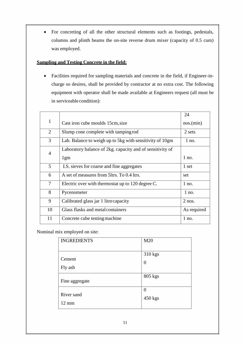
Sampling and Testing Concrete in the field:
Facilities required for sampling materials and concrete in the field, if Engineer-in-
charge so desires, shall be provided by contractor at no extra cost. The following
equipment with operator shall be made available at Engineers request (all must be
in serviceable condition):
1
Cast iron cube moulds 15cm, size
24
nos.(min)
2 Slump cone complete with tamping rod 2 sets
3 Lab. Balance to weigh up to 5kg with sensitivity of 10gm 1 no.
4 Laboratory balance of 2kg. capacity and of sensitivity of
1gm 1 no.
5 I.S. sieves for coarse and fine aggregates 1 set
6 A set of measures from 5ltrs. To 0.4 ltrs. set
7 Electric over with thermostat up to 120 degree C. 1 no.
8 Pycenometer 1 no.
9 Calibrated glass jar 1 litre capacity 2 nos.
10 Glass flasks and metal containers As required
11 Concrete cube testing machine 1 no.
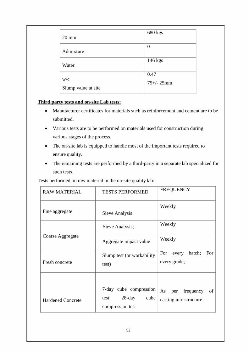
Nominal mix employed on site:
INGREDIENTS M20
Cement
Fly ash
310 kgs
0
Fine aggregate
805 kgs
River sand
12 mm
0
450 kgs
52
20 mm
680 kgs
Admixture
0
Water
146 kgs
w/c
Slump value at site
0.47
75+/- 25mm
Third party tests and on-site Lab tests:
Manufacturer certificates for materials such as reinforcement and cement are to be
submitted.
Various tests are to be performed on materials used for construction during
various stages of the process.
The on-site lab is equipped to handle most of the important tests required to
ensure quality.
The remaining tests are performed by a third-party in a separate lab specialized for
such tests.
Tests performed on raw material in the on-site quality lab:
RAW MATERIAL TESTS PERFORMED FREQUENCY
Fine aggregate
Sieve Analysis Weekly
Coarse Aggregate
Sieve Analysis; Weekly
Aggregate impact value Weekly
Fresh concrete Slump test (or workability
test)
For every batch; For
every grade;
Hardened Concrete
7-day cube compression
test; 28-day cube
compression test
As per frequency of
casting into structure

53
Steel
Rolling margin
For every lot; For every
diameter
Bricks
Dimension test
Water absorption tests
Compressive strength test
For every lot
Tests performed by third-party:
RAW MATERIAL TESTS PERFORMED FREQUENCY
Cement Fineness test ; Initial and
Final setting time;
Monthly; or
source changes
whenever
Coarse Aggregate
Specific gravity; water
absorption; flakiness
index; elongation index
Weekly; or
source changes
whenever
Fine aggregate
Physical properties
As per IS : 383-1970 Whenever source changes
Steel
Physical properties
Each lot; or
source changes
whenever
Tests performed on soil:
Proctor Compaction test IS:2720 PartVIII
Core Cutter test
CUBE TEST:
Cube test is the best way to ensure that the concrete cast on site will reach a
particular compressive strength. It is also a good way of testing that the concrete is
strong enough to support its own weight, plus the weight of anything it must
support.
Cubes of concrete are tested after 3,7 and 28 days. Here on site, cubes are tested
after 7 and 28 days.
54
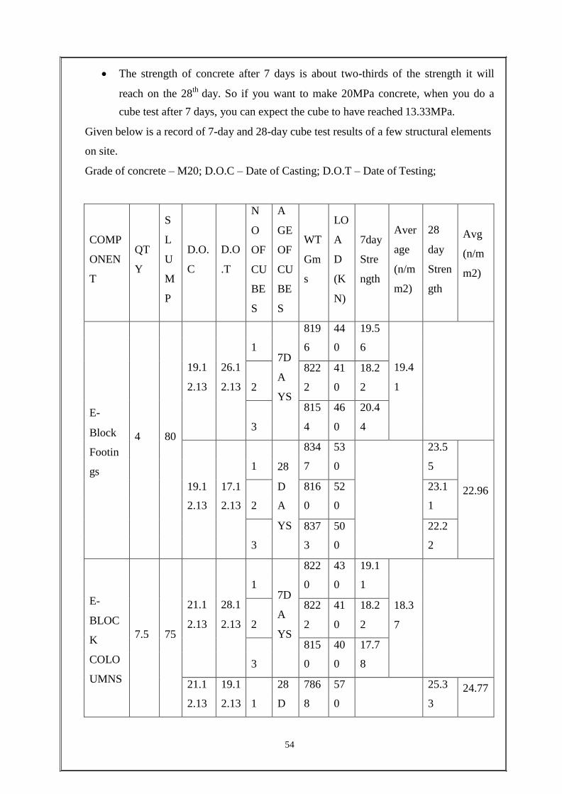
The strength of concrete after 7 days is about two-thirds of the strength it will
reach on the 28th day. So if you want to make 20MPa concrete, when you do a
cube test after 7 days, you can expect the cube to have reached 13.33MPa.
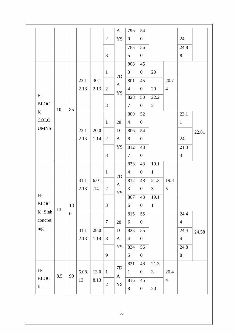
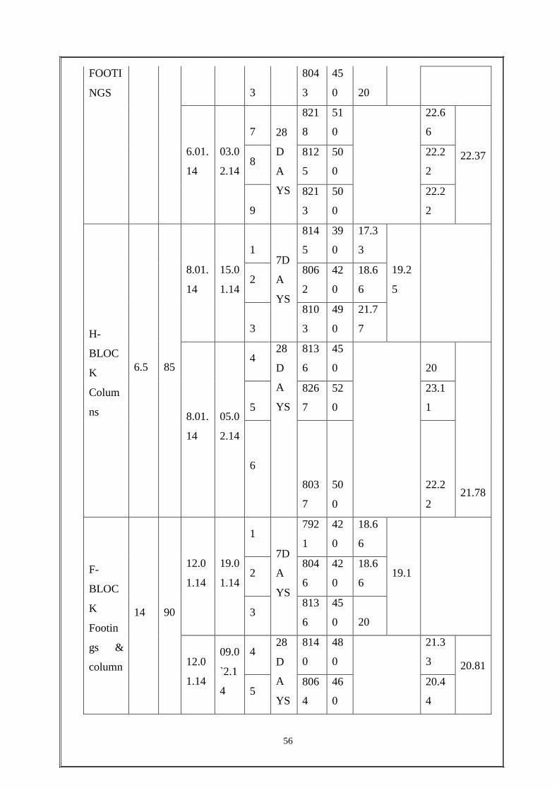
Given below is a record of 7-day and 28-day cube test results of a few structural elements
on site.
Grade of concrete – M20; D.O.C – Date of Casting; D.O.T – Date of Testing;
COMP
ONEN
T
QT
Y
S
L
U
M
P
D.O.
C
D.O
.T
N
O
OF
CU
BE
S
A
GE
OF
CU
BE
S
WT
Gm
s
LO
A
D
(K
N)
7day
Stre
ngth
Aver
age
(n/m
m2)
28
day
Stren
gth
Avg
(n/m
m2)
819 44 19.5
E-
19.1
2.13
26.1
2.13
1 7D
A
YS
6 0 6
19.4
1 2
822
2
41
0
18.2
2
815 46 20.4
Block
Footin 4 80
3 4 0 4
834 53 23.5
gs 1 28 7 0 5
19.1 17.1 D 816 52 23.1 22.96 2.13 2.13 2 A 0 0 1
YS 837 50 22.2
3 3 0 2
822 43 19.1
E-
BLOC
K
7.5
75
21.1
2.13
28.1
2.13
1 7D
A
YS
0 0 1
18.3
7 2
822
2
41
0
18.2
2
815 40 17.7 COLO 3 0 0 8
UMNS 21.1 19.1 28 786 57 25.3 24.77
2.13 2.13 1 D 8 0 3
55
2
A
YS
796
0
54
0
24
3
783
5
56
0
24.8
8
E-
BLOC
K
COLO
UMNS
10
85
23.1
2.13
30.1
2.13
1
7D
A
YS
808
3
45
0 20
20.7
4
2
801
4
45
0 20
3
828
7
50
0
22.2
2
23.1
2.13
20.0
1.14
1
28
D
A
YS
800
4
52
0
23.1
1
22.81
2
806
8
54
0 24
3
812
7
48
0
21.3
3
H-
BLOC
K Slab
concret
ing
13
13
0
31.1
2.13
6.01
.14
1
7D
A
YS
833
4
43
0
19.1
1
19.8
5
2
812
3
48
0
21.3
3
3
807
6
43
0
19.1
1
31.1
2.13
28.0
1.14
7
28
D
A
YS
815
6
55
0
24.4
4
24.58
8
823
4
55
0
24.4
4
9
834
5
56
0
24.8
8
H-
BLOC
K
8.5
90
6.08.
13
13.0
8.13
1
7D
A
YS
821
1
48
0
21.3
3 20.4
4
2 816
8
45
0 20
56
FOOTI
NGS
3
804
3
45
0
20
6.01.
14
03.0
2.14
7
28
D
A
YS
821
8
51
0
22.6
6
22.37 8
812
5
50
0
22.2
2
9
821
3
50
0
22.2
2
H-
BLOC
K
Colum
ns
6.5
85
8.01.
14
15.0
1.14
1
7D
A
YS
814
5
39
0
17.3
3
19.2
5
2 806
2
42
0
18.6
6
3
810
3
49
0
21.7
7
8.01.
14
05.0
2.14
4 28
D
A
YS
813
6
45
0
20
21.78
5
826
7
52
0
23.1
1
6
803
7
50
0
22.2
2
F-
BLOC
K
Footin
gs &
column
14
90
12.0
1.14
19.0
1.14
1
7D
A
YS
792
1
42
0
18.6
6
19.1
2 804
6
42
0
18.6
6
3 813
6
45
0 20
12.0
1.14
09.0
`2.1
4
4 28
D
A
YS
814
0
48
0
21.3
3
20.81
5 806
4
46
0
20.4
4
57
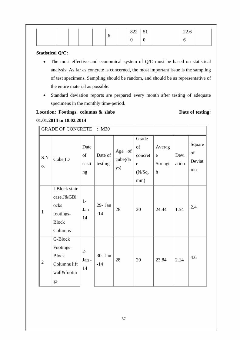
Statistical Q/C:
The most effective and economical system of Q/C must be based on statistical
analysis. As far as concrete is concerned, the most important issue is the sampling
of test specimens. Sampling should be random, and should be as representative of
the entire material as possible.
Standard deviation reports are prepared every month after testing of adequate
specimens in the monthly time-period.
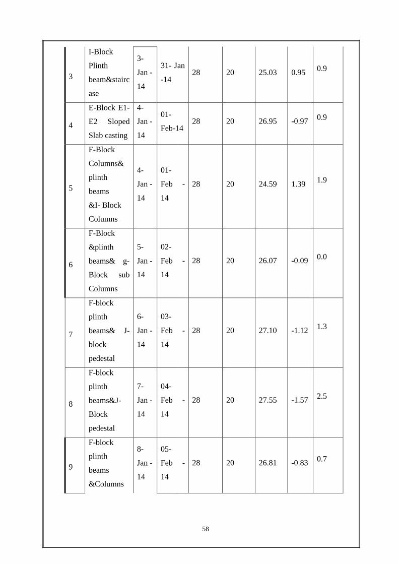
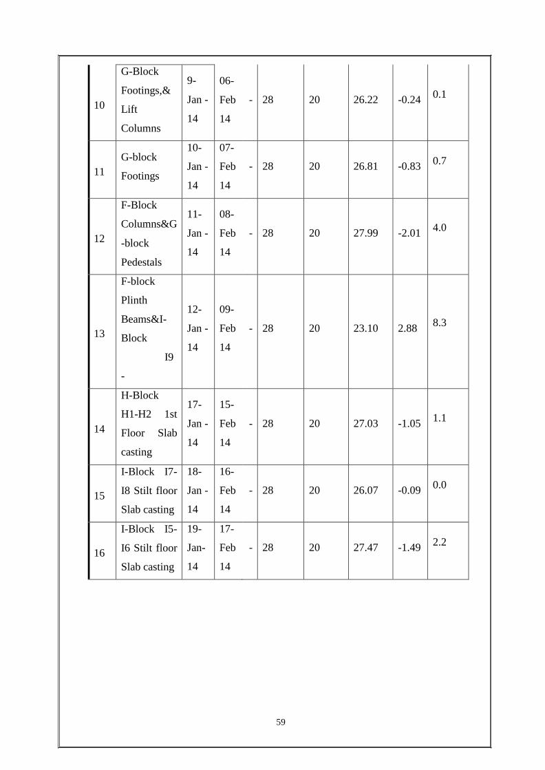
Location: Footings, columns & slabs Date of testing:
01.01.2014 to 18.02.2014
GRADE OF CONCRETE : M20
S.N
o.
Cube ID
Date
of
casti
ng
Date of
testing
Age of
cube(da
ys)
Grade
of
concret
e
(N/Sq.
mm)
Averag
e
Strengt
h
Devi
ation
Square
of
Deviat
ion
1
I-Block stair
case,J&GBl
ocks
footings-
Block
Columns
1-
Jan-
14
29- Jan
-14
28
20
24.44
1.54
2.4
2
G-Block
Footings-
Block
Columns lift
wall&footin
gs
2-
Jan -
14
30- Jan
-14
28
20
23.84
2.14
4.6
6 822 51
0 0
22.6
6
58
3
I-Block
Plinth
beam&stairc
ase
3-
Jan -
14
31- Jan
-14
28
20
25.03
0.95
0.9
4
E-Block E1-
E2 Sloped
Slab casting
4-
Jan -
14
01-
Feb-14
28
20
26.95
-0.97
0.9
5
F-Block
Columns&
plinth
beams
&I- Block
Columns
4-
Jan -
14
01-
Feb
14
-
28
20
24.59
1.39
1.9
6
F-Block
&plinth
beams& g-
Block sub
Columns
5-
Jan -
14
02-
Feb
14
-
28
20
26.07
-0.09
0.0
7
F-block
plinth
beams& J-
block
pedestal
6-
Jan -
14
03-
Feb
14
-
28
20
27.10
-1.12
1.3
8
F-block
plinth
beams&J-
Block
pedestal
7-
Jan -
14
04-
Feb
14
-
28
20
27.55
-1.57
2.5
9
F-block
plinth
beams
&Columns
8-
Jan -
14
05-
Feb
14
-
28
20
26.81
-0.83
0.7
59
10
G-Block
Footings,&
Lift
Columns
9-
Jan -
14
06-
Feb
14
-
28
20
26.22
-0.24
0.1
11
G-block
Footings
10-
Jan -
14
07-
Feb
14
-
28
20
26.81
-0.83
0.7
12
F-Block
Columns&G
-block
Pedestals
11-
Jan -
14
08-
Feb
14
-
28
20
27.99
-2.01
4.0
13
F-block
Plinth
Beams&I-
Block
I9
-
I10 Slab
casting
12-
Jan -
14
09-
Feb
14
-
28
20
23.10
2.88
8.3
14
H-Block
H1-H2 1st
Floor Slab
casting
17-
Jan -
14
15-
Feb
14
-
28
20
27.03
-1.05
1.1
15
I-Block I7-
I8 Stilt floor
Slab casting
18-
Jan -
14
16-
Feb
14
-
28
20
26.07
-0.09
0.0
16
I-Block I5-
I6 Stilt floor
Slab casting
19-
Jan-
14
17-
Feb
14
-
28
20
27.47
-1.49
2.2
60
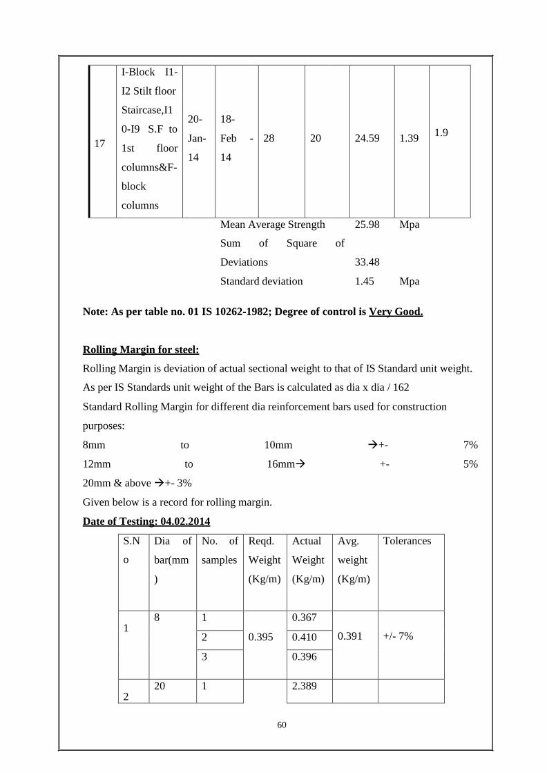
17
I-Block I1-
I2 Stilt floor
Staircase,I1
0-I9 S.F to
1st floor
columns&F-
block
columns
20-
Jan-
14
18-
Feb -
14
28
20
24.59
1.39
1.9
Mean Average Strength 25.98 Mpa
Sum of Square
Deviations
of
33.48
Standard deviation 1.45 Mpa
Note: As per table no. 01 IS 10262-1982; Degree of control is Very Good.
Rolling Margin for steel:
Rolling Margin is deviation of actual sectional weight to that of IS Standard unit weight.
As per IS Standards unit weight of the Bars is calculated as dia x dia / 162
Standard Rolling Margin for different dia reinforcement bars used for construction
purposes:
8mm to 10mm +- 7%
12mm to 16mm +- 5%
20mm & above +- 3%
Given below is a record for rolling margin.
Date of Testing: 04.02.2014
S.N
o
Dia of
bar(mm
)
No. of
samples
Reqd.
Weight
(Kg/m)
Actual
Weight
(Kg/m)
Avg.
weight
(Kg/m)
Tolerances
1
8 1
0.395
0.367 0.391
+/- 7% 2 0.410
3 0.396
2
20 1 2.389

61
2 2.47 2.416 2.4 +/-3%
3 2.396
3
16 1
1.58
1.523 1.529
+/- 5% 2 1.545
3 1.520
Monthly lab test reports:
The details of all the tests conducted on various materials in the site lab are documented
and a report summarizing all the conducted tests is prepared every month.
Given below is a record summarizing the quality tests conducted in the month of
February, 2014.
SUMMARY OF LAB TEST REPORT – JANUARY 2014
62
OTHER ROUTINE INSPECTIONS BY QUALITY DEPT.:
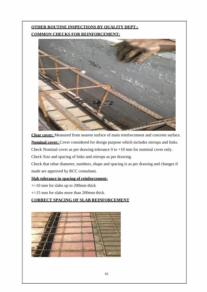
COMMON CHECKS FOR REINFORCEMENT:
Clear cover: Measured from nearest surface of main reinforcement and concrete surface.
Nominal cover: Cover considered for design purpose which includes stirrups and links.
Check Nominal cover as per drawing tolerance 0 to +10 mm for nominal cover only.
Check Size and spacing of links and stirrups as per drawing.
Check that rebar diameter, numbers, shape and spacing is as per drawing and changes if
made are approved by RCC consultant.
Slab tolerance in spacing of reinforcement:
+/-10 mm for slabs up to 200mm thick
+/-15 mm for slabs more than 200mm thick.
CORRECT SPACING OF SLAB REINFORCEMENT
63
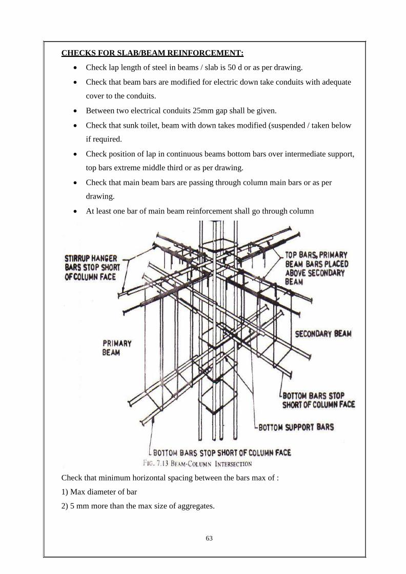
CHECKS FOR SLAB/BEAM REINFORCEMENT:
Check lap length of steel in beams / slab is 50 d or as per drawing.
Check that beam bars are modified for electric down take conduits with adequate
cover to the conduits.
Between two electrical conduits 25mm gap shall be given.
Check that sunk toilet, beam with down takes modified (suspended / taken below
if required.
Check position of lap in continuous beams bottom bars over intermediate support,
top bars extreme middle third or as per drawing.
Check that main beam bars are passing through column main bars or as per
drawing.
At least one bar of main beam reinforcement shall go through column
Check that minimum horizontal spacing between the bars max of :
1) Max diameter of bar
2) 5 mm more than the max size of aggregates.

64
Check spacing of stirrups, diameter, and shape as per drawing.
CHAIRS FOR SLABS
Chairs shall be designed to take manual and mechanical loads during slab casting
chair is meant to maintain spacing between two meshes of slab top and bottom.
Chair shall not be touching to shuttering or sheathing.
Check for rigidity, tightness and cleanliness. The formwork should not
sag/warp/hog or worn off. It should be free from l knots, splits, cracks, sawdust
and debris.
The formwork must be adequately supported, braced and tied.
COMMON CHECKS FOR STRUCTURE POST-CONCRETING
The exposed surface must be free from honeycombs, exposed rebars, grout loss,
segregation, bulging, cracks & formwork debris.
Check for accuracy within limits for cross-sectional dimensions (+10mm/ -5mm)
and services‟ opening (size: +/- 10mm; location: +/- 25mm) as per drawings,
using a measuring tape.
Alignment must be checked using a plumb bob.
Structural levelness should be checked using a theodolite. Height deviation of
structural level:
Above the datum on the level immediately below must be within limits: +/- 5mm
From the control bench mark must be within limits : +/- 10 mm
Visual checks for curing must be carried out.

MATERIAL MANAGEMENT
MATERIAL MANAGEMENT:
Material management is the process of planning, implementing and controlling the flow
or storage of input, facilities, service and information efficiently and effectively from the
point of supply to the point of consumption in the conformity of the company‟s objective.
Store Management may be defined as a systematic coordination and combination of
efforts in a manner, which would result in optimum efficiency with a minimum
expenditure.
The term Store, Storehouse, or Warehouse refers to a building or a room or a place where
materials are kept.
Functions of a Store
To receive raw materials, components, tools, equipment and other items and
account for them.
To provide adequate and proper storage and preservation to the various items.
To meet the demands of the consuming departments by proper issues and account
for the consumption.
To minimize obsolescence, surplus and scrap through proper codification,
preservation and handling.
To highlight stock accumulation, discrepancies and abnormal consumption and
effect control measures.
To ensure good housekeeping so that material handling, material preservation,
stocking, receipt and issue can be done adequately.
To assist in verification and provide supportive information for effective purchase
action.
STORAGE OF CEMENT AND AGGREGATE:
Cement must be kept dry at all times.
Cement bags must be stored on construction sites by first spreading a sheet of
plastic over the ground under the cement to keep away dampness rising from the
ground.
.All the cement bags shall be stacked up to a max. Height of 5 bags only.
Cement bags shall be stacked in such a manner that most of the load will be on
beams.
Cement bags shall be stacked on an elevated platform.
All the material shall be stacked near by the working area but not in working area.
In no case any material shall be stacked at winch.
Sand shall be stacked in a neat manner arresting the spillage by bundling around
sand.
STORAGE AND ISSUE OF REINFORCEMENT:
• Stock reinforcement on elevated pedestals of minimum 150 mm above ground
level cover with PVC sheets
• Issue reinforcement on FISRT-IN-FIRST-OUT BASIS to minimize oxidation
loss.
• Keep record of all steel issued from storage yard to cutting and bending yard.
• In case of theft lodge FIR and register claim with insurance company
HANDLING OF REINFORCEMENT:
Avoid re bend, reshape and straighten bent bars
Use tractor trailer for internal shifting of reinforcement in the project area.
Avoid manual shifting as far as possible.
Shift only the required qty of cut and bent bars to nearest location where bars are
to be fixed.

PHOTO GALLERY
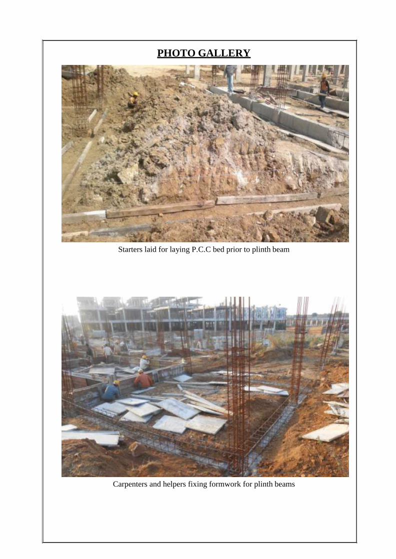
PHOTO GALLERY
Starters laid for laying P.C.C bed prior to plinth beam
Carpenters and helpers fixing formwork for plinth beams
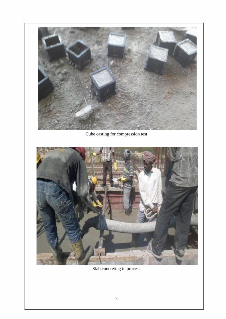
Cube casting for compression test
Slab concreting in process
68
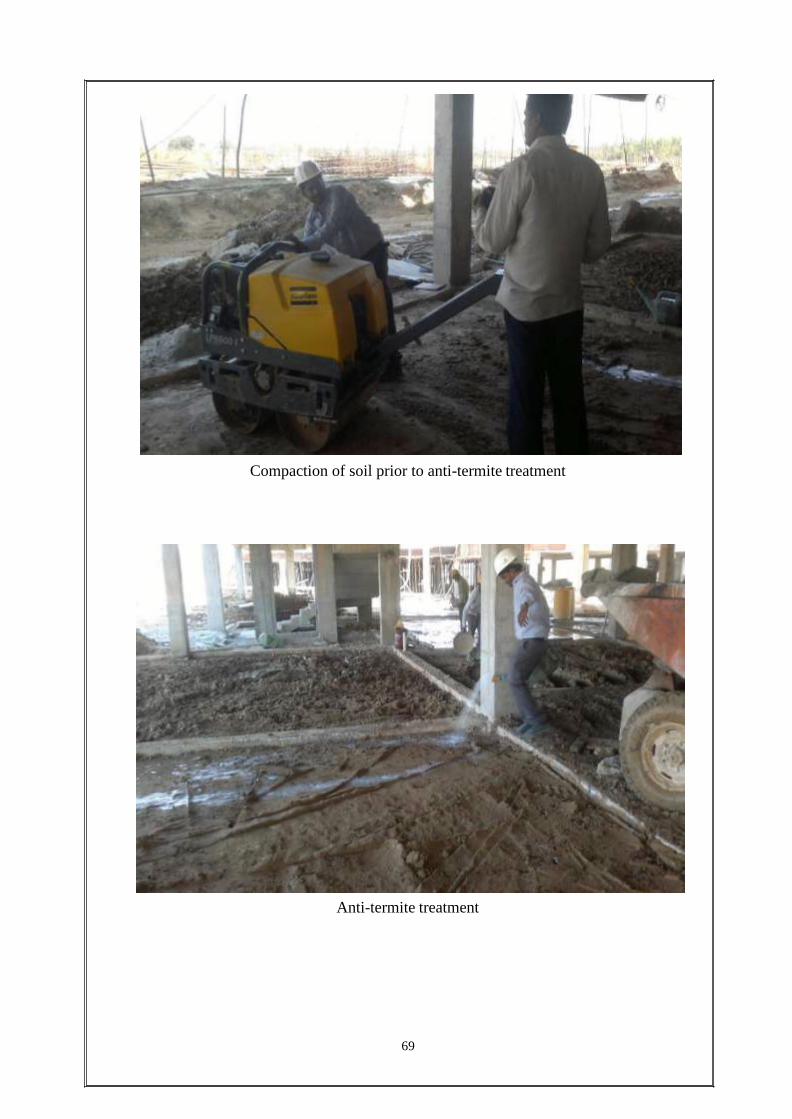
Compaction of soil prior to anti-termite treatment
Anti-termite treatment
69

70
Cubes arranged for compression test in lab
Formwork of a Raft (lift) footing partially flooded due to rain.
71
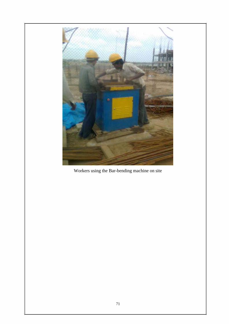
Workers using the Bar-bending machine on site

FINAL SUMMARY

FINAL SUMMARY

CONCLUSION
CONCLUSION
It was an absolute privilege to undergo my training at Galacon Infra &Projects (P) Ltd for
Sunway Opus Flexi Villas Project, Hyderabad, A.P. It was indeed a learning experience and
went a long way in increasing my knowledge and skill. It was wonderful to work alongside a
highly skilled and experienced workforce at one of the major construction sites in the
country. It gave me an opportunity to learn about various aspects of civil engineering. I learnt
about the implementation of various techniques and methods being used for construction. I
also learnt how the entire work site is managed and how the various activities are planned.
I feel proud to have worked at this project and I am thankful to GALCON infrastructure pvt
ltd for having given me the opportunity.
In the process of carrying out this project, we learnt to apply the theoretical aspects of
estimation on a live project. We have learnt the process of Estimation and Costing and we
understood that it is an essential aspect in a project for the arrangement of financial resources
necessary for the completion of the job.
Our calculation it are based on precise measurements which gave us approximate and
accurate values. The structural estimate had been prepared in detail such that the values can
be used in the actual project being carried out.
Also, the abstract of the estimated cost was prepared such that the current on going rate per
unit of each item of work were considered. Hence the estimated costs of the structural
requirements of the project are accurate too.
Therefore, this project is not a rough, but fairly accurate in its results of both the estimated
quantities as well as the estimated cost, and is quite useful for the ongoing project on which it
is made.