esx_storage_deployment_guide_updated_v2
TRANSCRIPT
Dell Inc Page 1
DellTM PowerVaultTM Configuration Guide for VMware ESX/ESXi 3.5 September 2008 Dell Virtualization Solutions Engineering Dell PowerVault Storage Engineering www.dell.com/vmware www.dell.com/powervault
Dell Inc Page 2
Table of Contents 1 Introduction ................................................................................................................. 3 2 Support Matrix ............................................................................................................ 3 3 Dell iSCSI Storage Arrays .......................................................................................... 4
3.1 PowerVault MD3000i .......................................................................................... 4 3.1.1 Reference Solution ........................................................................................ 4 3.1.2 MD3000i iSCSI Software Initiator Configuration ........................................ 7 3.1.3 MD3000i Storage Setup and Configuration ............................................... 10 3.1.4 Configure MD3000i Storage on ESX/ESXi ............................................... 15
3.2 PowerVault NX1950 .......................................................................................... 17 3.2.1 Reference Solution ...................................................................................... 17 3.2.2 NX1950 storage setup and configuration ................................................... 18 3.2.3 NX1950 iSCSI Software Initiator Configuration on ESX Server .............. 19 3.2.4 iSCSI Target and Virtual Disk Configuration on NX1950 ......................... 21 3.2.5 Configure NX1950 iSCSI Storage on ESX Server ..................................... 23
4 Dell Direct Attached Storage Arrays ........................................................................ 25 4.1 PowerVault MD3000 ......................................................................................... 25
4.1.1 Reference Configuration ............................................................................. 25 4.2 PowerVault MD1000 and MD1120 ................................................................... 26
4.2.1 Reference Configuration ............................................................................. 26 5 References ................................................................................................................. 27
Dell Inc Page 3
1 Introduction This document describes configuration steps to deploy solutions with VMware ESX/ESXi 3.5 on Dell™ PowerVault™ storage device. VMware ESX/ESXi 3.5 will be referred to as ESX for the remainder of the document. If any provision or steps is specific to ESX 3.5 or ESXi 3.5, it will be explicitly stated. Configuring Dell Equallogic and Dell | EMC storage is out of the scope for this document.
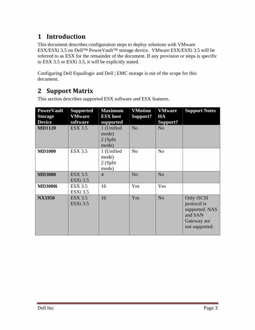
2 Support Matrix This section describes supported ESX software and ESX features. PowerVault Storage Device
Supported VMware software
Maximum ESX host supported
VMotion Support?
VMware HA Support?
Support Notes
MD1120 ESX 3.5 1 (Unified mode) 2 (Split mode)
No No
MD1000 ESX 3.5 1 (Unified mode) 2 (Split mode)
No No
MD3000 ESX 3.5 ESXi 3.5
4 No No
MD3000i ESX 3.5 ESXi 3.5
16 Yes Yes
NX1950 ESX 3.5 ESXi 3.5
16 Yes No Only iSCSI protocol is supported. NAS and SAN Gateway are not supported.
Dell Inc Page 4
3 Dell iSCSI Storage Arrays
3.1 PowerVault MD3000i The Dell™ PowerVault™ MD3000i storage solution can enable either a standard or high availability configuration. The standard configuration has a MD3000i with a single controller with two 1GbE iSCSI ports. It can be deployed to support up to 16 ESX hosts non-redundantly. The high availability configuration has MD3000i with dual controllers, each with two 1GbE iSCSI per controller for a total of four 1GbE ports. The dual controller option can connect up to 16 fully redundant hosts. Each MD3000i controller also contains an Ethernet port (not an iSCSI port) for out-of-band management. Provisioning of storage on servers in a VM environment is a multiple step process starting with definition of the server names for host access. The iSCSI connection is then established from the storage subsystem, and after detection and configuration is established as a two way link with the associated ESX server(s), completing the iSCSI communication subsystem. The final step allocates the detected storage to the individual virtual machines (VM’s), where all or part of the configured storage can be assigned to individual VM’s. Note: NIC teaming is supported by the MD3000i only with VMware ESX/ESXi 3.5. The MD3000i does not support NIC teaming with other operating systems. Note: All NICs in a vSwitch must be in the same broadcast domain. If you connect the NICs directly to the MD3000i, they will not be accessible on a broadcast.
3.1.1 Reference Solution The following configurations illustrate recommended deployment for the MD3000i with ESX.
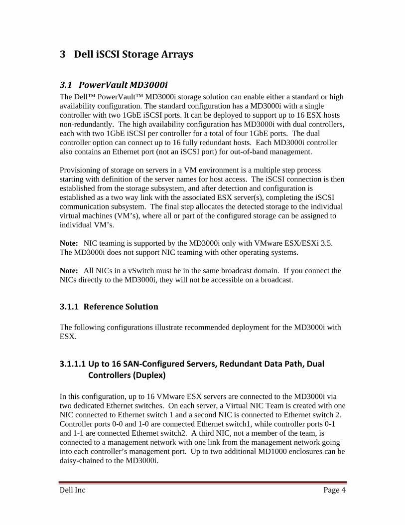
3.1.1.1 Up to 16 SAN‐Configured Servers, Redundant Data Path, Dual Controllers (Duplex)
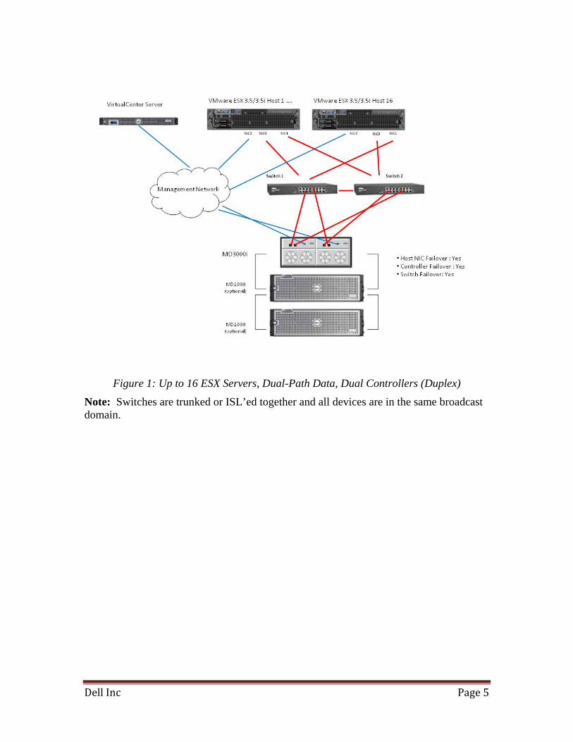
In this configuration, up to 16 VMware ESX servers are connected to the MD3000i via two dedicated Ethernet switches. On each server, a Virtual NIC Team is created with one NIC connected to Ethernet switch 1 and a second NIC is connected to Ethernet switch 2. Controller ports 0-0 and 1-0 are connected Ethernet switch1, while controller ports 0-1 and 1-1 are connected Ethernet switch2. A third NIC, not a member of the team, is connected to a management network with one link from the management network going into each controller’s management port. Up to two additional MD1000 enclosures can be daisy-chained to the MD3000i.
Dell Inc Page 5
Figure 1: Up to 16 ESX Servers, Dual-Path Data, Dual Controllers (Duplex)
Note: Switches are trunked or ISL’ed together and all devices are in the same broadcast domain.
Dell Inc Page 6
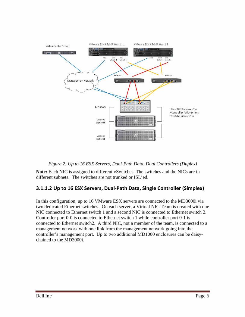
Figure 2: Up to 16 ESX Servers, Dual-Path Data, Dual Controllers (Duplex)
Note: Each NIC is assigned to different vSwitches. The switches and the NICs are in different subnets. The switches are not trunked or ISL’ed.
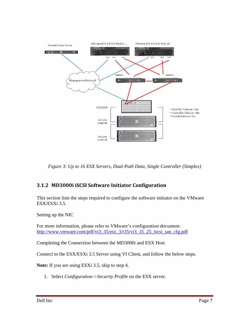
3.1.1.2 Up to 16 ESX Servers, Dual‐Path Data, Single Controller (Simplex) In this configuration, up to 16 VMware ESX servers are connected to the MD3000i via two dedicated Ethernet switches. On each server, a Virtual NIC Team is created with one NIC connected to Ethernet switch 1 and a second NIC is connected to Ethernet switch 2. Controller port 0-0 is connected to Ethernet switch 1 while controller port 0-1 is connected to Ethernet switch2. A third NIC, not a member of the team, is connected to a management network with one link from the management network going into the controller’s management port. Up to two additional MD1000 enclosures can be daisy-chained to the MD3000i.
Dell Inc Page 7
Figure 3: Up to 16 ESX Servers, Dual-Path Data, Single Controller (Simplex)
3.1.2 MD3000i iSCSI Software Initiator Configuration This section lists the steps required to configure the software initiator on the VMware ESX/ESXi 3.5. Setting up the NIC For more information, please refer to VMware’s configuration document: http://www.vmware.com/pdf/vi3_35/esx_3/r35/vi3_35_25_iscsi_san_cfg.pdf Completing the Connection between the MD3000i and ESX Host Connect to the ESX/ESXi 3.5 Server using VI Client, and follow the below steps. Note: If you are using ESXi 3.5, skip to step 4.
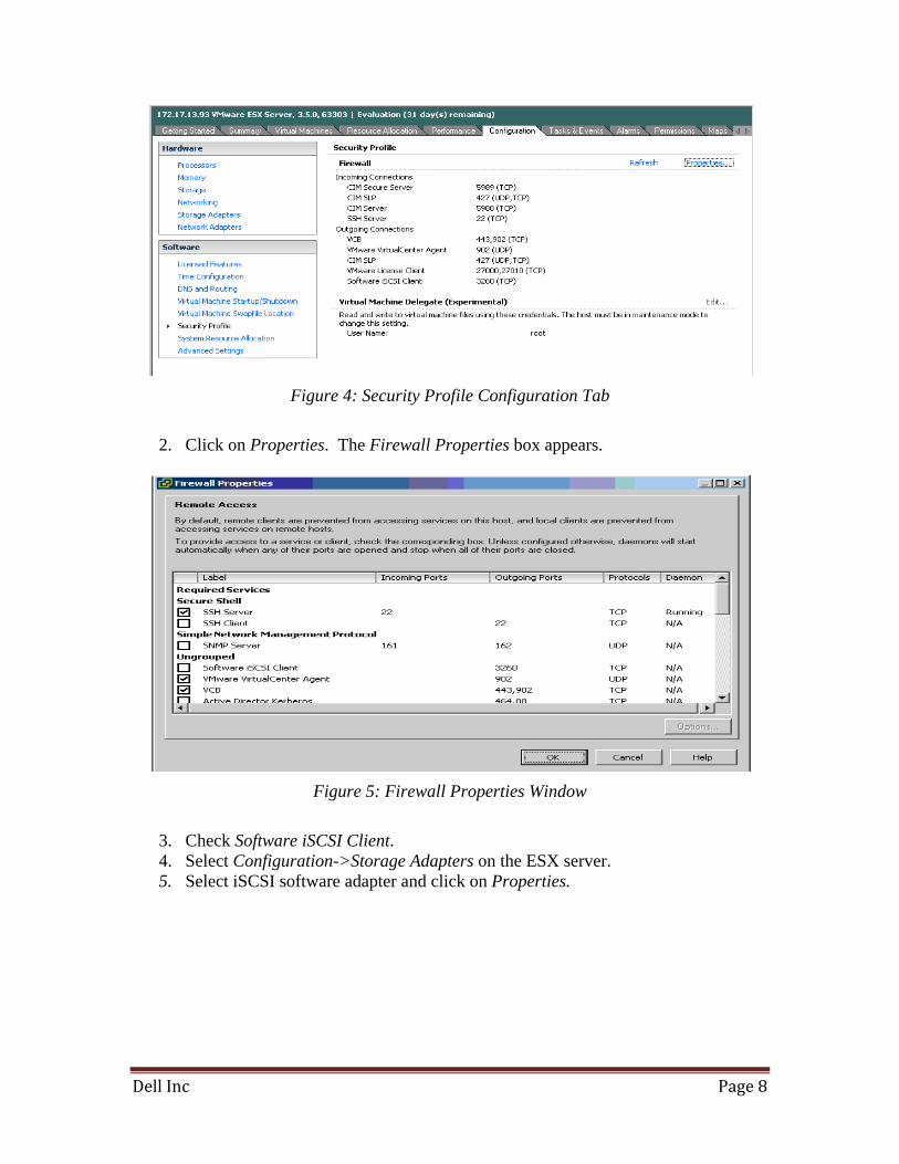
1. Select Configuration->Security Profile on the ESX server.
Dell Inc Page 8
Figure 4: Security Profile Configuration Tab
2. Click on Properties. The Firewall Properties box appears.
Figure 5: Firewall Properties Window
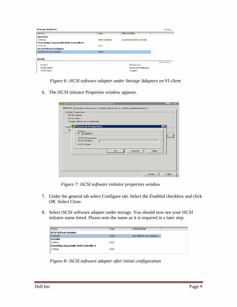
3. Check Software iSCSI Client. 4. Select Configuration->Storage Adapters on the ESX server. 5. Select iSCSI software adapter and click on Properties.
Dell Inc Page 9
6. The iSCSI initiator Properties window appears.
7. Under the general tab select Configure tab. Select the Enabled checkbox and click OK. Select Close.
8. Select iSCSI software adapter under storage. You should now see your iSCSI
initiator name listed. Please note the name as it is required in a later step.
Figure 6: iSCSI software adapter under Storage Adapters on VI client
Figure 7: iSCSI software initiator properties window
Figure 8: iSCSI software adapter after initial configuration
Dell Inc Page 10
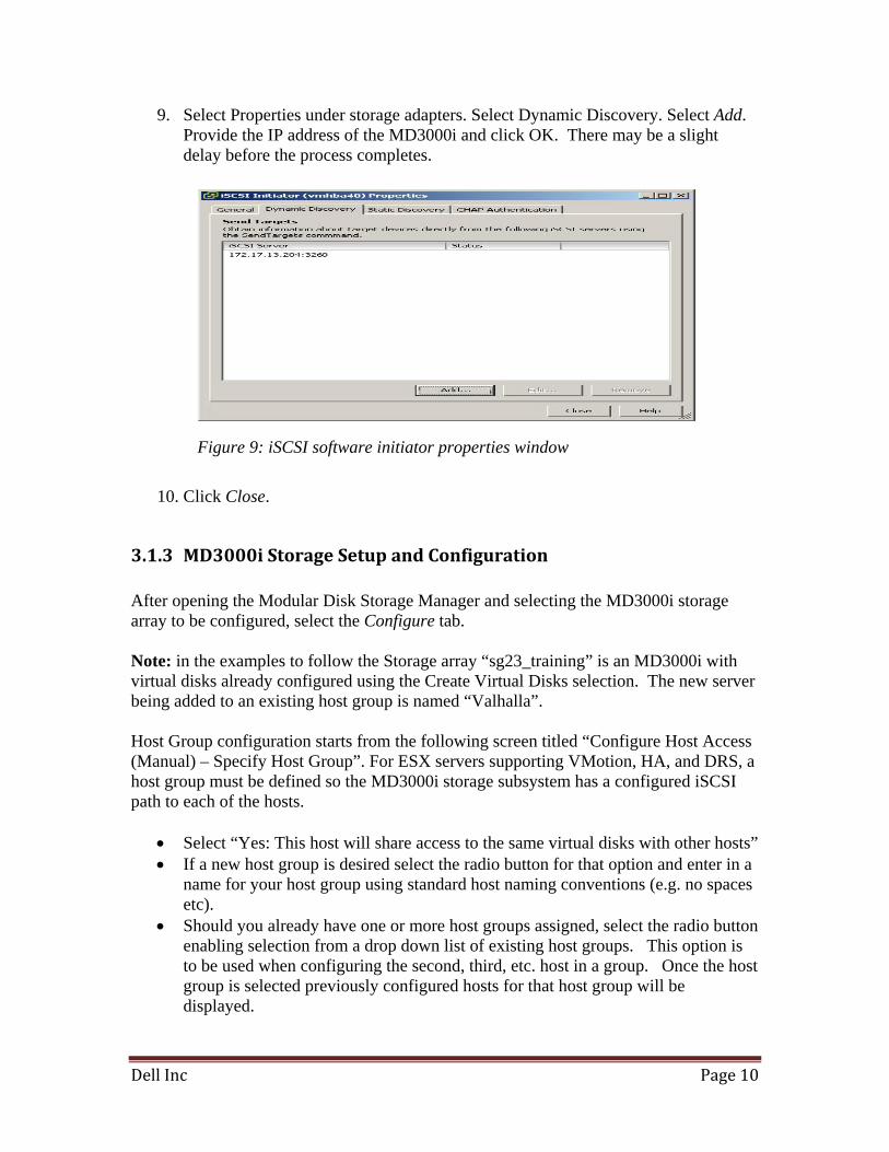
9. Select Properties under storage adapters. Select Dynamic Discovery. Select Add. Provide the IP address of the MD3000i and click OK. There may be a slight delay before the process completes.
10. Click Close.
3.1.3 MD3000i Storage Setup and Configuration After opening the Modular Disk Storage Manager and selecting the MD3000i storage array to be configured, select the Configure tab. Note: in the examples to follow the Storage array “sg23_training” is an MD3000i with virtual disks already configured using the Create Virtual Disks selection. The new server being added to an existing host group is named “Valhalla”. Host Group configuration starts from the following screen titled “Configure Host Access (Manual) – Specify Host Group”. For ESX servers supporting VMotion, HA, and DRS, a host group must be defined so the MD3000i storage subsystem has a configured iSCSI path to each of the hosts.
• Select “Yes: This host will share access to the same virtual disks with other hosts” • If a new host group is desired select the radio button for that option and enter in a
name for your host group using standard host naming conventions (e.g. no spaces etc).
• Should you already have one or more host groups assigned, select the radio button enabling selection from a drop down list of existing host groups. This option is to be used when configuring the second, third, etc. host in a group. Once the host group is selected previously configured hosts for that host group will be displayed.
Figure 9: iSCSI software initiator properties window
Dell Inc Page 11
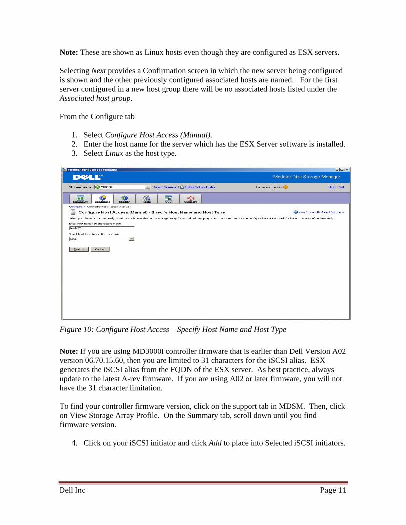
Note: These are shown as Linux hosts even though they are configured as ESX servers. Selecting Next provides a Confirmation screen in which the new server being configured is shown and the other previously configured associated hosts are named. For the first server configured in a new host group there will be no associated hosts listed under the Associated host group. From the Configure tab
1. Select Configure Host Access (Manual). 2. Enter the host name for the server which has the ESX Server software is installed. 3. Select Linux as the host type.
Figure 10: Configure Host Access – Specify Host Name and Host Type
Note: If you are using MD3000i controller firmware that is earlier than Dell Version A02 version 06.70.15.60, then you are limited to 31 characters for the iSCSI alias. ESX generates the iSCSI alias from the FQDN of the ESX server. As best practice, always update to the latest A-rev firmware. If you are using A02 or later firmware, you will not have the 31 character limitation. To find your controller firmware version, click on the support tab in MDSM. Then, click on View Storage Array Profile. On the Summary tab, scroll down until you find firmware version.
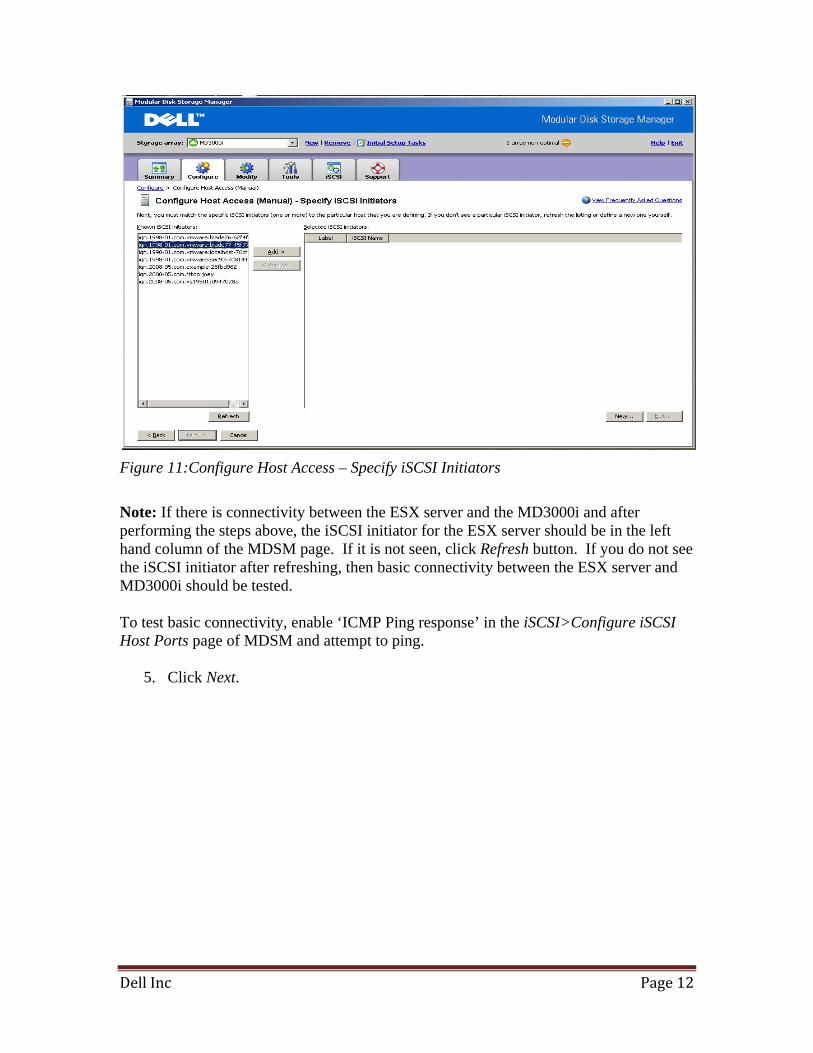
4. Click on your iSCSI initiator and click Add to place into Selected iSCSI initiators.
Dell Inc Page 12
Figure 11:Configure Host Access – Specify iSCSI Initiators
Note: If there is connectivity between the ESX server and the MD3000i and after performing the steps above, the iSCSI initiator for the ESX server should be in the left hand column of the MDSM page. If it is not seen, click Refresh button. If you do not see the iSCSI initiator after refreshing, then basic connectivity between the ESX server and MD3000i should be tested. To test basic connectivity, enable ‘ICMP Ping response’ in the iSCSI>Configure iSCSI Host Ports page of MDSM and attempt to ping.
5. Click Next.
Dell Inc Page 13
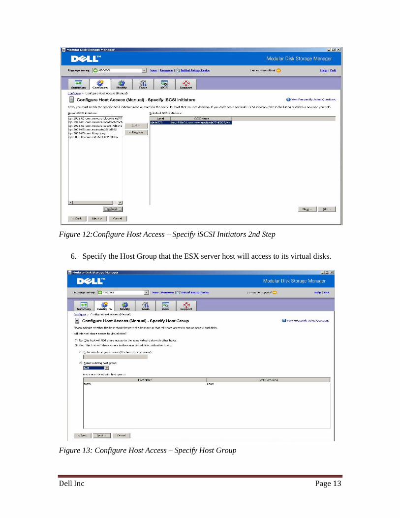
Figure 12:Configure Host Access – Specify iSCSI Initiators 2nd Step
6. Specify the Host Group that the ESX server host will access to its virtual disks.
Figure 13: Configure Host Access – Specify Host Group
Dell Inc Page 14
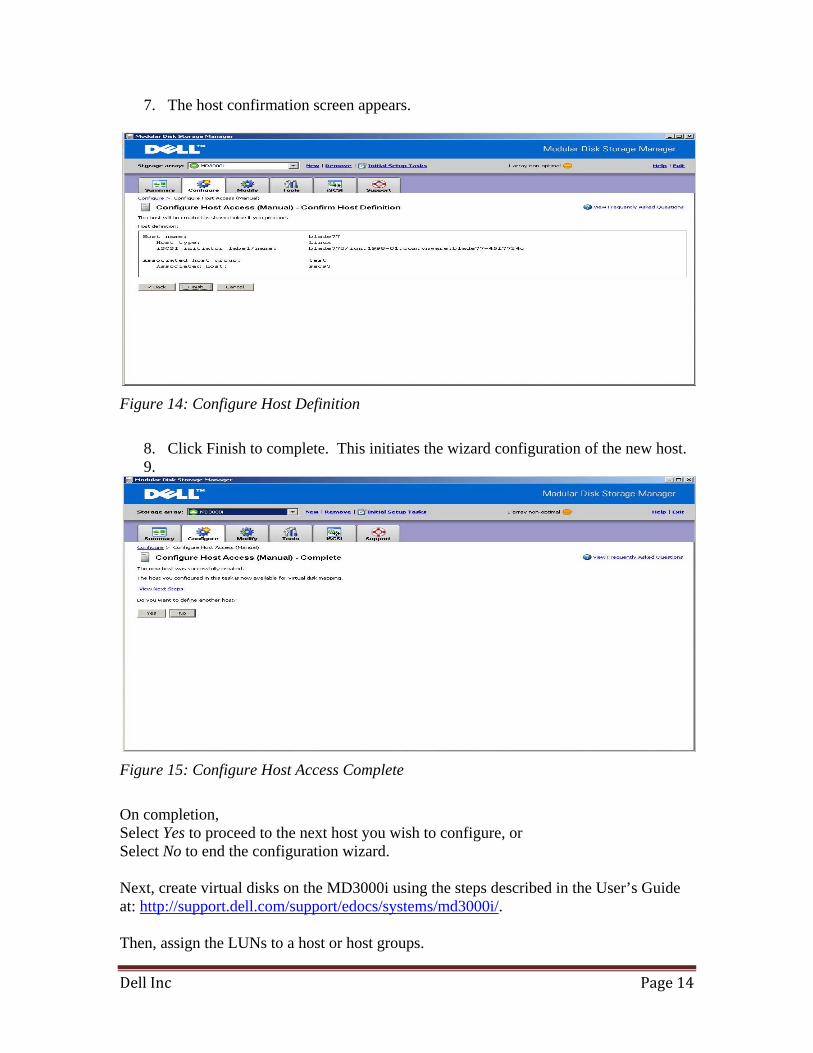
7. The host confirmation screen appears.
Figure 14: Configure Host Definition
8. Click Finish to complete. This initiates the wizard configuration of the new host. 9.
Figure 15: Configure Host Access Complete
On completion, Select Yes to proceed to the next host you wish to configure, or Select No to end the configuration wizard. Next, create virtual disks on the MD3000i using the steps described in the User’s Guide at: http://support.dell.com/support/edocs/systems/md3000i/. Then, assign the LUNs to a host or host groups.
Dell Inc Page 15
1. If you want to group individual hosts, in MDSM, click on the Configure tab.
Otherwise, go to step 3. 2. Click on Create Host Group and add the hosts that you would like to have shared
access to the same virtual disks. 3. From the Configure tab, click on Create Host-to-Virtual Disk Mappings. 4. Click on the host or host group that you want to map to a LUN and click Next. 5. Select the virtual disk that you want that host or host group to have access to. 6. Click Finish. On the following pop-up window, click complete.
You now have LUNs that are ready for use with ESX/ESXi.
3.1.4 Configure MD3000i Storage on ESX/ESXi Connect to the ESX/ESXi server/Virtual Center using VI Client and follow the steps below.
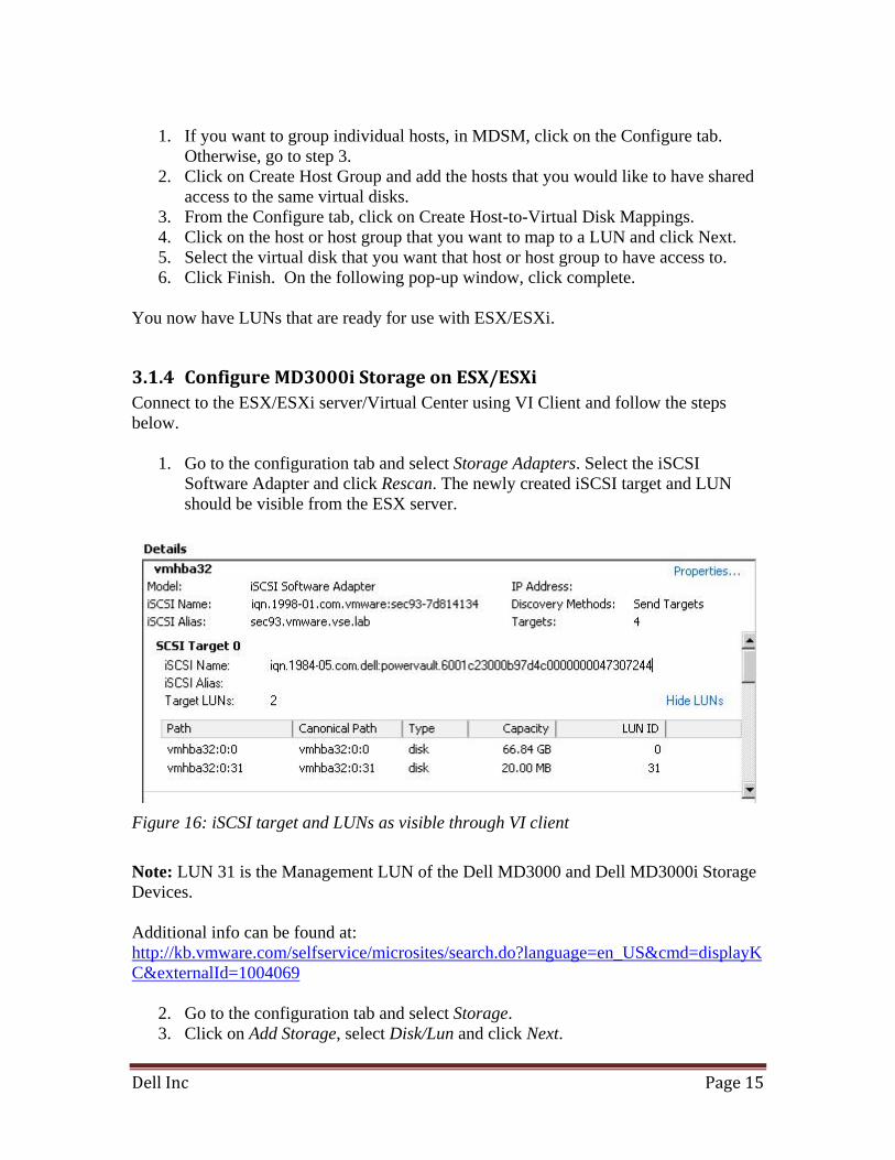
1. Go to the configuration tab and select Storage Adapters. Select the iSCSI Software Adapter and click Rescan. The newly created iSCSI target and LUN should be visible from the ESX server.
Figure 16: iSCSI target and LUNs as visible through VI client
Note: LUN 31 is the Management LUN of the Dell MD3000 and Dell MD3000i Storage Devices. Additional info can be found at: http://kb.vmware.com/selfservice/microsites/search.do?language=en_US&cmd=displayKC&externalId=1004069
2. Go to the configuration tab and select Storage. 3. Click on Add Storage, select Disk/Lun and click Next.
Dell Inc Page 16
4. Select the newly added storage and click Next. 5. Select the newly created iSCSI LUN and click Next. 6. Review the disk layout and click Next. 7. Provide a name for the VMFS datastore and click Next. 8. Select the appropriate block size and capacity for the VMFS datastore and click
Next. 9. Review the disk layout and click Finish to create the VMFS datastore. The new
datastore is now ready to be used for storing virtual machine images.
Dell Inc Page 17
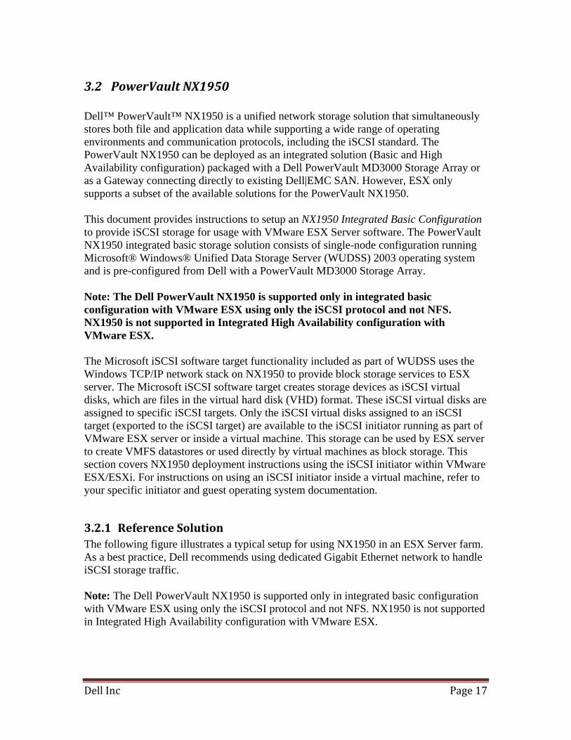
3.2 PowerVault NX1950 Dell™ PowerVault™ NX1950 is a unified network storage solution that simultaneously stores both file and application data while supporting a wide range of operating environments and communication protocols, including the iSCSI standard. The PowerVault NX1950 can be deployed as an integrated solution (Basic and High Availability configuration) packaged with a Dell PowerVault MD3000 Storage Array or as a Gateway connecting directly to existing Dell|EMC SAN. However, ESX only supports a subset of the available solutions for the PowerVault NX1950. This document provides instructions to setup an NX1950 Integrated Basic Configuration to provide iSCSI storage for usage with VMware ESX Server software. The PowerVault NX1950 integrated basic storage solution consists of single-node configuration running Microsoft® Windows® Unified Data Storage Server (WUDSS) 2003 operating system and is pre-configured from Dell with a PowerVault MD3000 Storage Array. Note: The Dell PowerVault NX1950 is supported only in integrated basic configuration with VMware ESX using only the iSCSI protocol and not NFS. NX1950 is not supported in Integrated High Availability configuration with VMware ESX. The Microsoft iSCSI software target functionality included as part of WUDSS uses the Windows TCP/IP network stack on NX1950 to provide block storage services to ESX server. The Microsoft iSCSI software target creates storage devices as iSCSI virtual disks, which are files in the virtual hard disk (VHD) format. These iSCSI virtual disks are assigned to specific iSCSI targets. Only the iSCSI virtual disks assigned to an iSCSI target (exported to the iSCSI target) are available to the iSCSI initiator running as part of VMware ESX server or inside a virtual machine. This storage can be used by ESX server to create VMFS datastores or used directly by virtual machines as block storage. This section covers NX1950 deployment instructions using the iSCSI initiator within VMware ESX/ESXi. For instructions on using an iSCSI initiator inside a virtual machine, refer to your specific initiator and guest operating system documentation.
3.2.1 Reference Solution The following figure illustrates a typical setup for using NX1950 in an ESX Server farm. As a best practice, Dell recommends using dedicated Gigabit Ethernet network to handle iSCSI storage traffic. Note: The Dell PowerVault NX1950 is supported only in integrated basic configuration with VMware ESX using only the iSCSI protocol and not NFS. NX1950 is not supported in Integrated High Availability configuration with VMware ESX.
Dell Inc Page 18
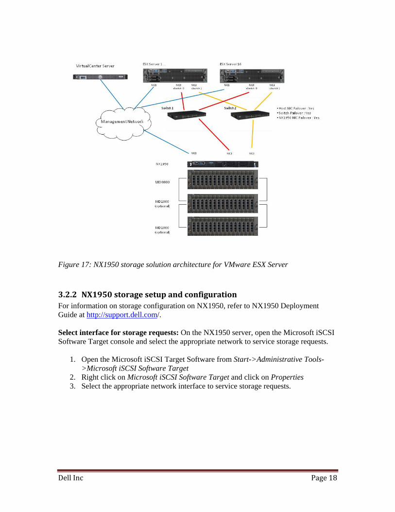
Figure 17: NX1950 storage solution architecture for VMware ESX Server
3.2.2 NX1950 storage setup and configuration For information on storage configuration on NX1950, refer to NX1950 Deployment Guide at http://support.dell.com/. Select interface for storage requests: On the NX1950 server, open the Microsoft iSCSI Software Target console and select the appropriate network to service storage requests.
1. Open the Microsoft iSCSI Target Software from Start->Administrative Tools->Microsoft iSCSI Software Target
2. Right click on Microsoft iSCSI Software Target and click on Properties 3. Select the appropriate network interface to service storage requests.
Dell Inc Page 19
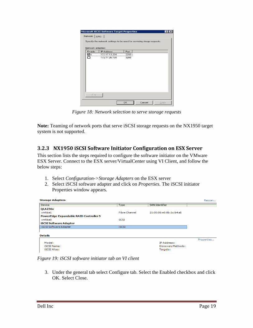
Figure 18: Network selection to serve storage requests
Note: Teaming of network ports that serve iSCSI storage requests on the NX1950 target system is not supported.
3.2.3 NX1950 iSCSI Software Initiator Configuration on ESX Server This section lists the steps required to configure the software initiator on the VMware ESX Server. Connect to the ESX server/VirtualCenter using VI Client, and follow the below steps:
1. Select Configuration->Storage Adapters on the ESX server 2. Select iSCSI software adapter and click on Properties. The iSCSI initiator
Properties window appears.
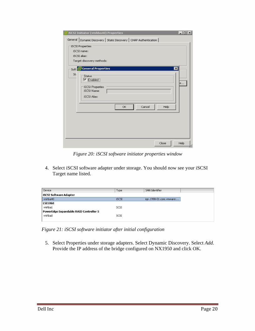
Figure 19: iSCSI software initiator tab on VI client
3. Under the general tab select Configure tab. Select the Enabled checkbox and click
OK. Select Close.
Dell Inc Page 20
Figure 20: iSCSI software initiator properties window
4. Select iSCSI software adapter under storage. You should now see your iSCSI
Target name listed.
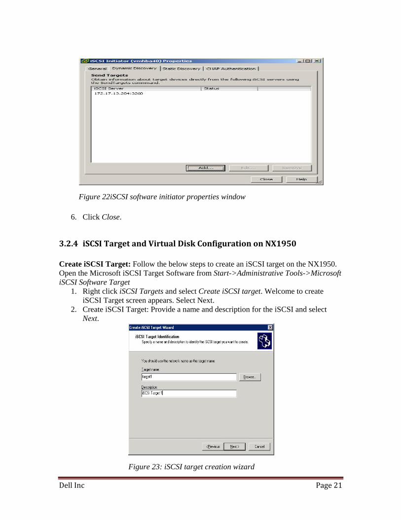
5. Select Properties under storage adapters. Select Dynamic Discovery. Select Add.
Provide the IP address of the bridge configured on NX1950 and click OK.
Figure 21: iSCSI software initiator after initial configuration
Dell Inc Page 21
6. Click Close.
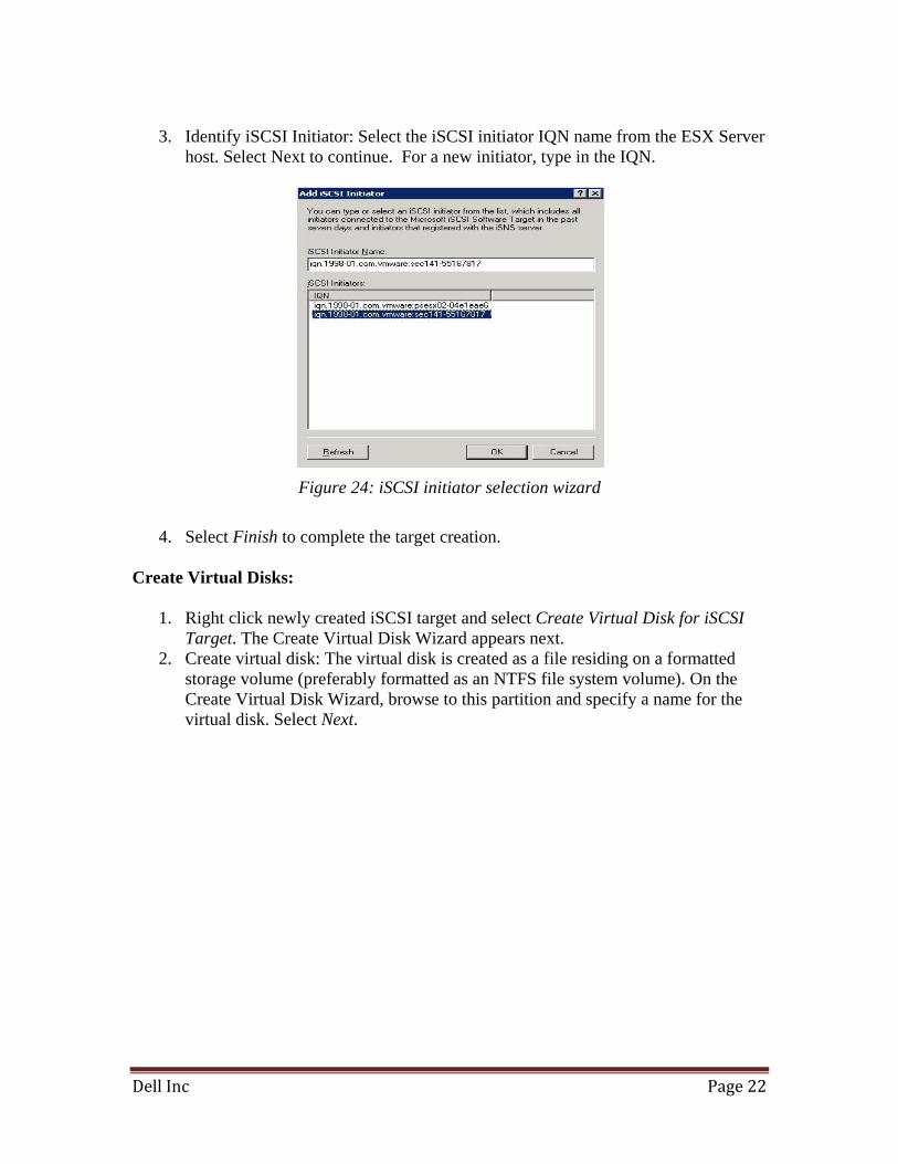
3.2.4 iSCSI Target and Virtual Disk Configuration on NX1950 Create iSCSI Target: Follow the below steps to create an iSCSI target on the NX1950. Open the Microsoft iSCSI Target Software from Start->Administrative Tools->Microsoft iSCSI Software Target
1. Right click iSCSI Targets and select Create iSCSI target. Welcome to create iSCSI Target screen appears. Select Next.
2. Create iSCSI Target: Provide a name and description for the iSCSI and select Next.
Figure 22iSCSI software initiator properties window
Figure 23: iSCSI target creation wizard
Dell Inc Page 22
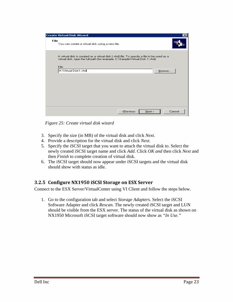
3. Identify iSCSI Initiator: Select the iSCSI initiator IQN name from the ESX Server
host. Select Next to continue. For a new initiator, type in the IQN.
Figure 24: iSCSI initiator selection wizard
4. Select Finish to complete the target creation.
Create Virtual Disks:
1. Right click newly created iSCSI target and select Create Virtual Disk for iSCSI Target. The Create Virtual Disk Wizard appears next.
2. Create virtual disk: The virtual disk is created as a file residing on a formatted storage volume (preferably formatted as an NTFS file system volume). On the Create Virtual Disk Wizard, browse to this partition and specify a name for the virtual disk. Select Next.
Dell Inc Page 23
3. Specify the size (in MB) of the virtual disk and click Next. 4. Provide a description for the virtual disk and click Next. 5. Specify the iSCSI target that you want to attach the virtual disk to. Select the
newly created iSCSI target name and click Add. Click OK and then click Next and then Finish to complete creation of virtual disk.
6. The iSCSI target should now appear under iSCSI targets and the virtual disk should show with status as idle.
3.2.5 Configure NX1950 iSCSI Storage on ESX Server Connect to the ESX Server/VirtualCenter using VI Client and follow the steps below.
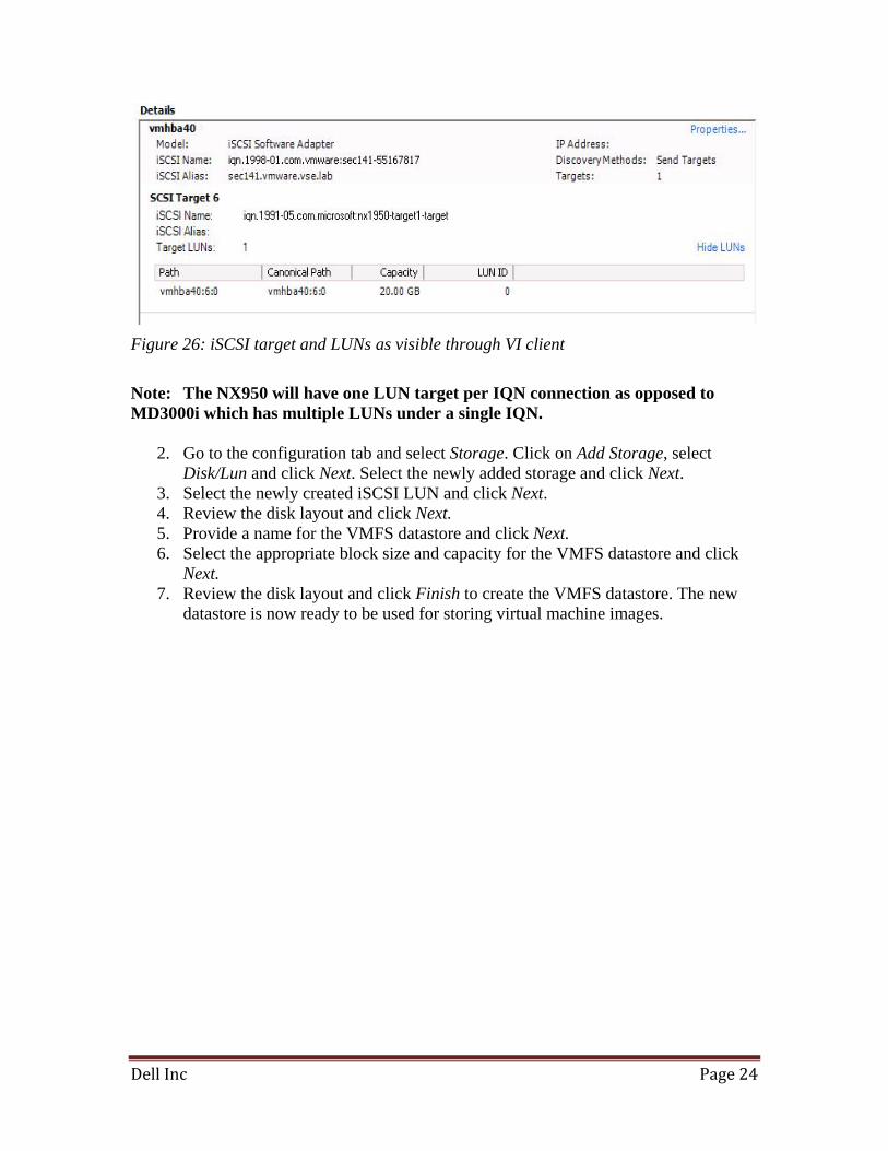
1. Go to the configuration tab and select Storage Adapters. Select the iSCSI Software Adapter and click Rescan. The newly created iSCSI target and LUN should be visible from the ESX server. The status of the virtual disk as shown on NX1950 Microsoft iSCSI target software should now show as “In Use.”
Figure 25: Create virtual disk wizard
Dell Inc Page 24
Figure 26: iSCSI target and LUNs as visible through VI client
Note: The NX950 will have one LUN target per IQN connection as opposed to MD3000i which has multiple LUNs under a single IQN.
2. Go to the configuration tab and select Storage. Click on Add Storage, select Disk/Lun and click Next. Select the newly added storage and click Next.
3. Select the newly created iSCSI LUN and click Next. 4. Review the disk layout and click Next. 5. Provide a name for the VMFS datastore and click Next. 6. Select the appropriate block size and capacity for the VMFS datastore and click
Next. 7. Review the disk layout and click Finish to create the VMFS datastore. The new
datastore is now ready to be used for storing virtual machine images.
Dell Inc Page 25
4 Dell Direct Attached Storage Arrays
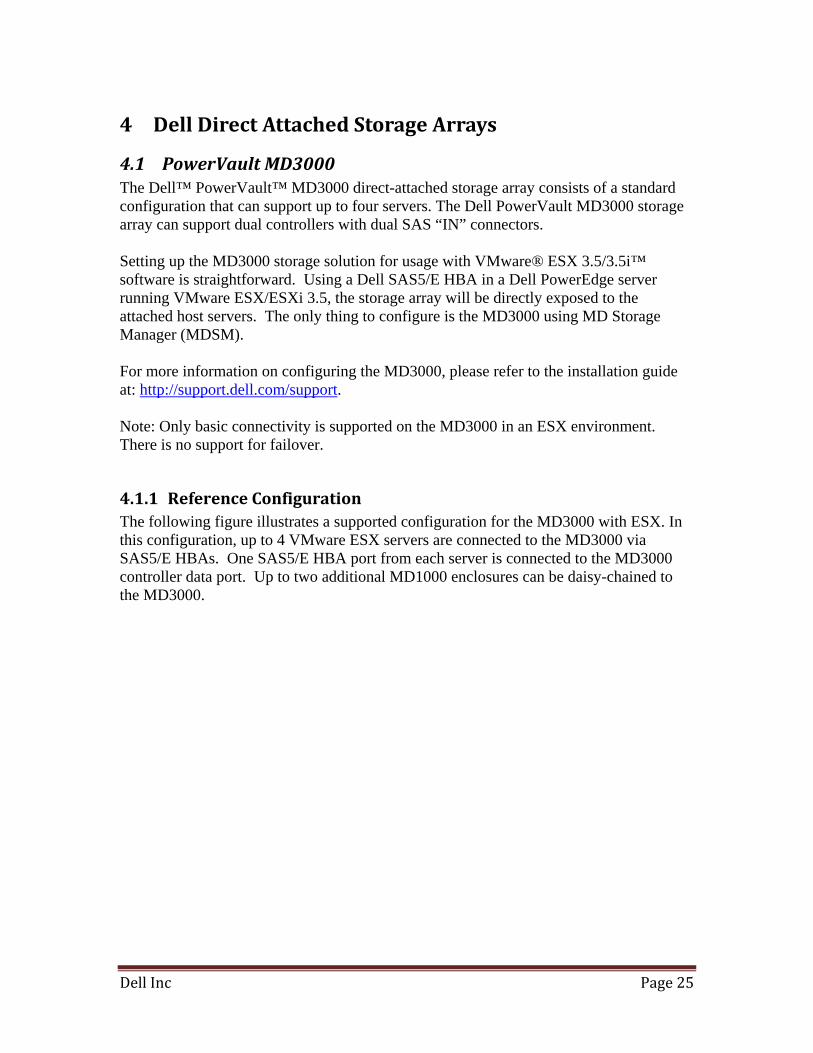
4.1 PowerVault MD3000 The Dell™ PowerVault™ MD3000 direct-attached storage array consists of a standard configuration that can support up to four servers. The Dell PowerVault MD3000 storage array can support dual controllers with dual SAS “IN” connectors. Setting up the MD3000 storage solution for usage with VMware® ESX 3.5/3.5i™ software is straightforward. Using a Dell SAS5/E HBA in a Dell PowerEdge server running VMware ESX/ESXi 3.5, the storage array will be directly exposed to the attached host servers. The only thing to configure is the MD3000 using MD Storage Manager (MDSM). For more information on configuring the MD3000, please refer to the installation guide at: http://support.dell.com/support. Note: Only basic connectivity is supported on the MD3000 in an ESX environment. There is no support for failover.
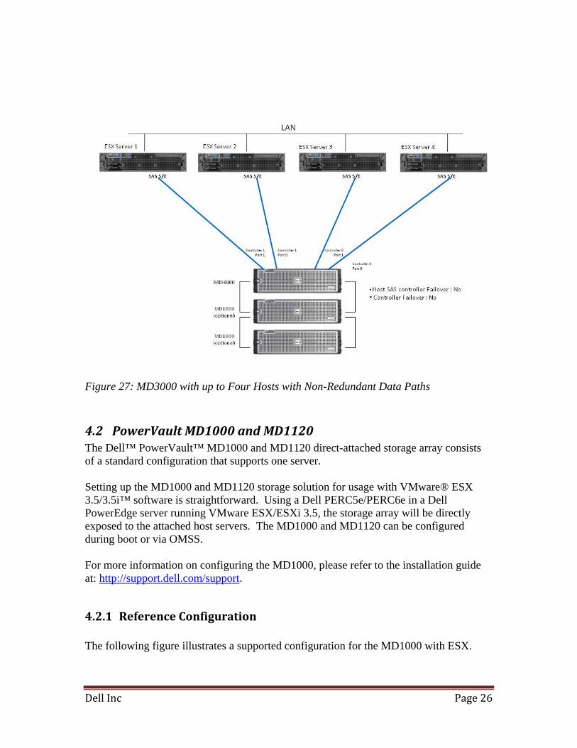
4.1.1 Reference Configuration The following figure illustrates a supported configuration for the MD3000 with ESX. In this configuration, up to 4 VMware ESX servers are connected to the MD3000 via SAS5/E HBAs. One SAS5/E HBA port from each server is connected to the MD3000 controller data port. Up to two additional MD1000 enclosures can be daisy-chained to the MD3000.
Dell Inc Page 26
Figure 27: MD3000 with up to Four Hosts with Non-Redundant Data Paths
4.2 PowerVault MD1000 and MD1120 The Dell™ PowerVault™ MD1000 and MD1120 direct-attached storage array consists of a standard configuration that supports one server. Setting up the MD1000 and MD1120 storage solution for usage with VMware® ESX 3.5/3.5i™ software is straightforward. Using a Dell PERC5e/PERC6e in a Dell PowerEdge server running VMware ESX/ESXi 3.5, the storage array will be directly exposed to the attached host servers. The MD1000 and MD1120 can be configured during boot or via OMSS. For more information on configuring the MD1000, please refer to the installation guide at: http://support.dell.com/support.
4.2.1 Reference Configuration The following figure illustrates a supported configuration for the MD1000 with ESX.
Dell Inc Page 27
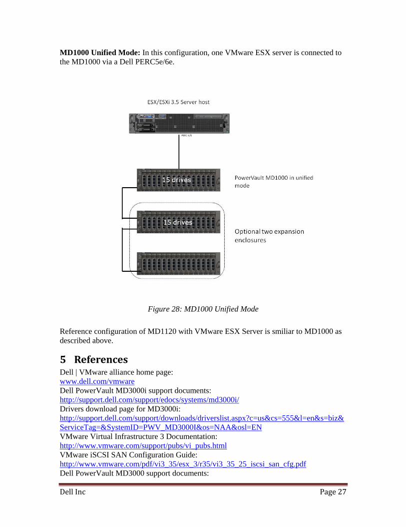
MD1000 Unified Mode: In this configuration, one VMware ESX server is connected to the MD1000 via a Dell PERC5e/6e.
Figure 28: MD1000 Unified Mode
Reference configuration of MD1120 with VMware ESX Server is smiliar to MD1000 as described above.
5 References Dell | VMware alliance home page: www.dell.com/vmware Dell PowerVault MD3000i support documents: http://support.dell.com/support/edocs/systems/md3000i/ Drivers download page for MD3000i: http://support.dell.com/support/downloads/driverslist.aspx?c=us&cs=555&l=en&s=biz&ServiceTag=&SystemID=PWV_MD3000I&os=NAA&osl=EN VMware Virtual Infrastructure 3 Documentation: http://www.vmware.com/support/pubs/vi_pubs.html VMware iSCSI SAN Configuration Guide: http://www.vmware.com/pdf/vi3_35/esx_3/r35/vi3_35_25_iscsi_san_cfg.pdf Dell PowerVault MD3000 support documents:
Dell Inc Page 28
http://support.dell.com/support/edocs/systems/md3000/ Drivers download page for MD3000: http://support.dell.com/support/downloads/driverslist.aspx?os=NAA&osl=EN&catid=-1&impid=-1&servicetag=&SystemID=PWV_MD3000&hidos=LHS64&hidlang=enDell PowerVault NX1950 support documents: http://support.dell.com/support/edocs/software/PVNX1950/ Drivers download page for NX1950: http://support.dell.com/support/downloads/driverslist.aspx?os=WX64&osl=EN&catid=-1&impid=-1&servicetag=&SystemID=PWV_NX_1950&hidos=WNET&hidlang=en PowerVault MD1000 support documents: http://support.dell.com/support/edocs/systems/md1000/ Drivers download page for MD1000: http://support.dell.com/support/downloads/driverslist.aspx?c=us&l=en&s=gen&ServiceTag=&SystemID=PWV_MD1000&os=WNET&osl=en&catid=&impid= Microsoft Widows Unified Storage Data Storage Server: http://www.microsoft.com/windowsserversystem/storage/wudss.mspx THIS DOCUMENT IS FOR INFORMATIONAL PURPOSES ONLY, AND MAY CONTAIN TYPOGRAPHICAL ERRORS AND TECHNICAL INACCURACIES. THE CONTENT IS PROVIDED AS IS, WITHOUT EXPRESS OR IMPLIED WARRANTIES OF ANY KIND. Microsoft and Windows are registered trademarks of Microsoft Corporation. VMware is a registered trademark and VMotion, Virtual SMP, and ESX/ESXi 3.5 are trademarks of VMware, Inc. Intel and Xeon are registered trademarks of Intel Corp. Other trademarks and trade names may be used in this document to refer to either the entities claiming the marks and names or their products. Dell disclaims proprietary interest in the marks and names of others.