etabs tutorial: frames - christian brothers...
TRANSCRIPT
ETABS Tutorial: Frames
Below is a tutorial that was organized for educational purposes at Christian Brothers University
only. The frame example below is given in Structural Analysis, 9th
ed. (Hibbeler, 2015).
Example 9.10
The moment of inertia of each frame member is I = 600 in4 and E = 29(10
3) ksi.
Solution
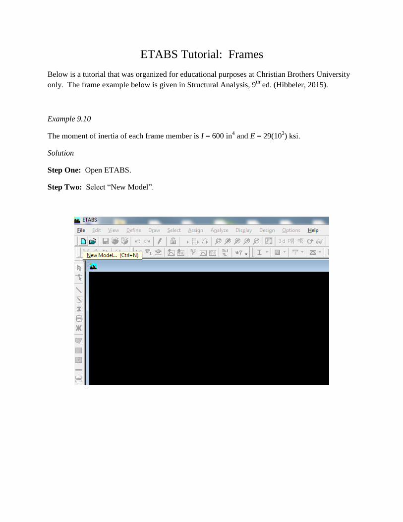
Step One: Open ETABS.
Step Two: Select “New Model”.
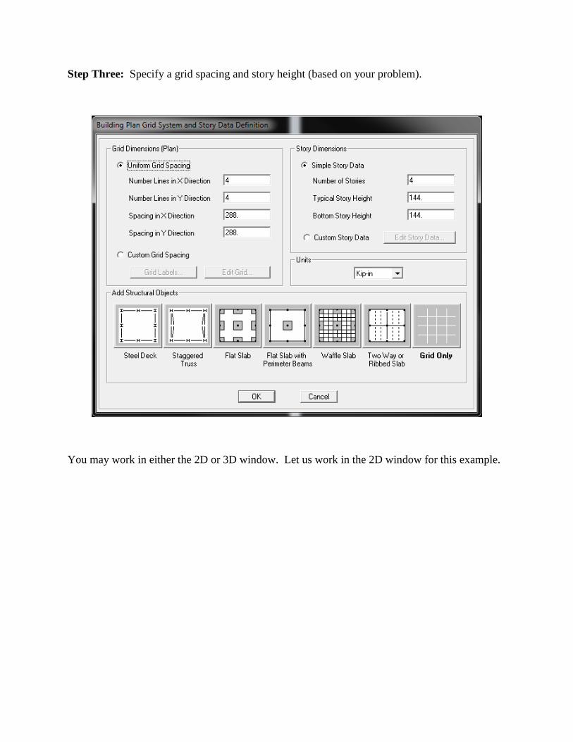
Step Three: Specify a grid spacing and story height (based on your problem).
You may work in either the 2D or 3D window. Let us work in the 2D window for this example.
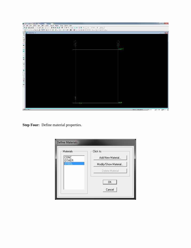
Step Four: Define material properties.

Modify the material properties by making the mass and weight per unit volume zero. By doing
this, we will assume the material weight is zero so as to not induce unwanted shears and
moments.
Step Five: Define frame sections.

For this example, we are given I = 600 in4 for all members. Let us select a rectangular cross
section and use this for all of our members. We can back calculate the dimensions of the
rectangular cross-section since we know the moment of inertia.

Step Six: Now we shall draw our members. Make sure you select the frame section that you
defined earlier.
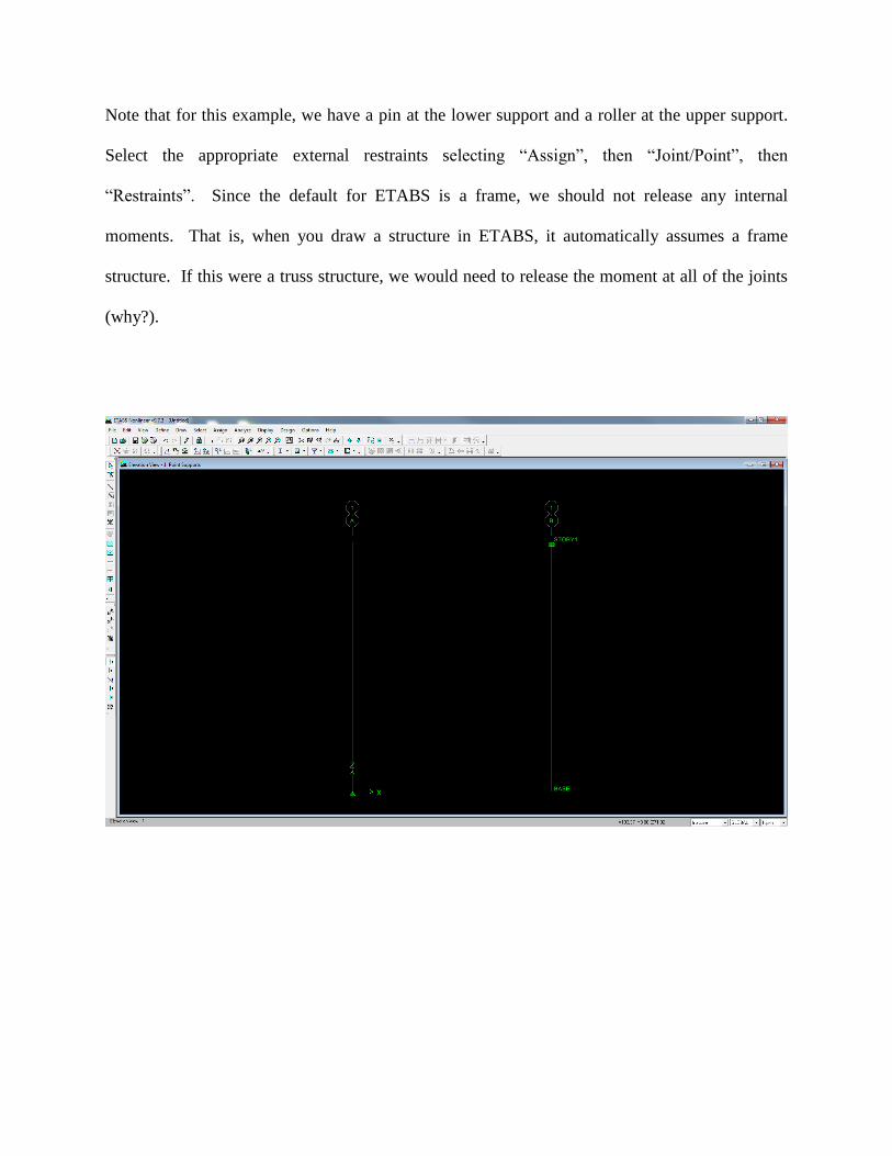
Note that for this example, we have a pin at the lower support and a roller at the upper support.
Select the appropriate external restraints selecting “Assign”, then “Joint/Point”, then
“Restraints”. Since the default for ETABS is a frame, we should not release any internal
moments. That is, when you draw a structure in ETABS, it automatically assumes a frame
structure. If this were a truss structure, we would need to release the moment at all of the joints
(why?).
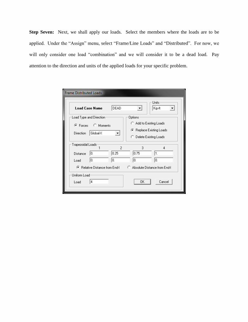
Step Seven: Next, we shall apply our loads. Select the members where the loads are to be
applied. Under the “Assign” menu, select “Frame/Line Loads” and “Distributed”. For now, we
will only consider one load “combination” and we will consider it to be a dead load. Pay
attention to the direction and units of the applied loads for your specific problem.
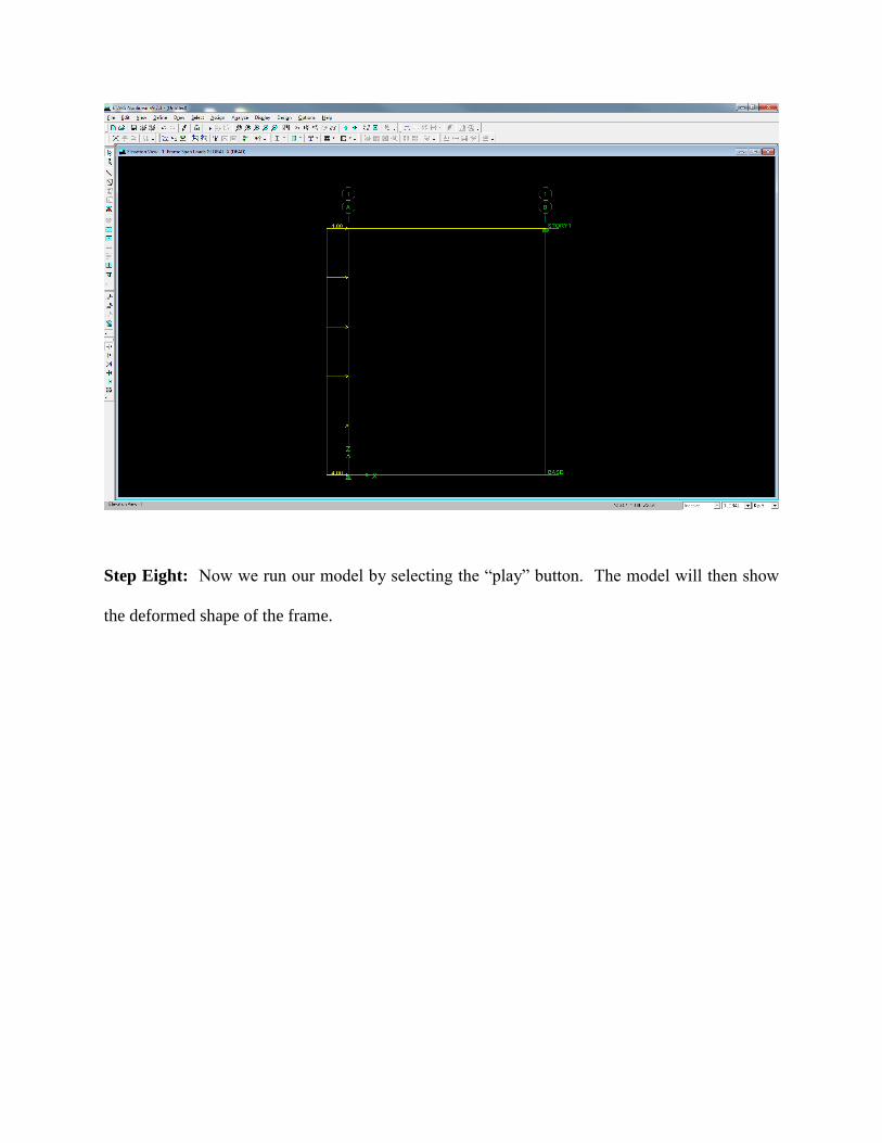
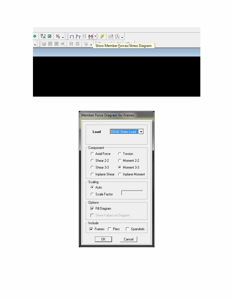
Step Eight: Now we run our model by selecting the “play” button. The model will then show
the deformed shape of the frame.
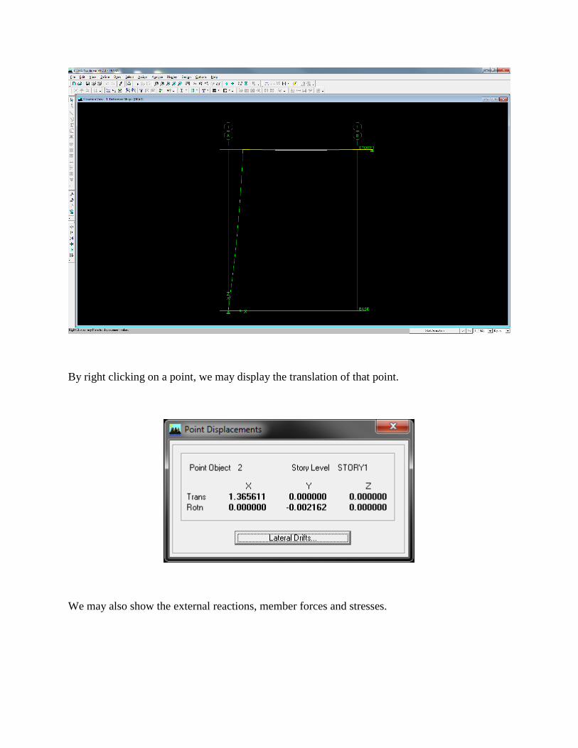
By right clicking on a point, we may display the translation of that point.
We may also show the external reactions, member forces and stresses.