etac: electronic transmission automotive control
TRANSCRIPT

ETAC: Electronic Transmission Automotive Control
User’s Manual
EATON ETAC Control: Electronic Transmission Automotive Control User’s Manual E-HYOV-TM002-E September 20072
Table of Contents
General
General . . . . . . . . . . . . . . . . . . . . . . . . . . . . . . . . . . . . . . . . . . . . . . . . . . . . . . . . . . . . . . . .2
Electronic Transmission Automotive Control (ETAC™): Design Features & Benefits . 3
Schematic Diagram & Optional Control System Upgrades . . . . . . . . . . . . . . . . . . . . . .4
ETAC and Pump Control & Control Orifice Selection . . . . . . . . . . . . . . . . . . . . . . . . . . .5
Autodrive Performance Curve . . . . . . . . . . . . . . . . . . . . . . . . . . . . . . . . . . . . . . . . . . . . . .6
MAESTRO Installment Requirements . . . . . . . . . . . . . . . . . . . . . . . . . . . . . . . . . . . . . . . .7
Connector . . . . . . . . . . . . . . . . . . . . . . . . . . . . . . . . . . . . . . . . . . . . . . . . . . . . . . . . . . . . . .8
Graphical User Interface . . . . . . . . . . . . . . . . . . . . . . . . . . . . . . . . . . . . . . . . . . . . . . . . . .9
Graphical User Interface Interconnect Diagram . . . . . . . . . . . . . . . . . . . . . . . . . . . . . . .10
ETAC MAESTRO Specifications . . . . . . . . . . . . . . . . . . . . . . . . . . . . . . . . . . . . . . . . . . . .11
Shifter Assy (F-N-R) . . . . . . . . . . . . . . . . . . . . . . . . . . . . . . . . . . . . . . . . . . . . . . . . . . . . . .12
Inching Pedal . . . . . . . . . . . . . . . . . . . . . . . . . . . . . . . . . . . . . . . . . . . . . . . . . . . . . . . . . . .13
ETAC Installation Guidelines . . . . . . . . . . . . . . . . . . . . . . . . . . . . . . . . . . . . . . . . . . . . . .14
ETAC Diagnostic Codes . . . . . . . . . . . . . . . . . . . . . . . . . . . . . . . . . . . . . . . . . . . . . . . . . .15
Typical ETAC Installation . . . . . . . . . . . . . . . . . . . . . . . . . . . . . . . . . . . . . . . . . . . . . . . . .16
Questionnaire - Application Data Sheet . . . . . . . . . . . . . . . . . . . . . . . . . . . . . . . . . . . . .17
Eaton Corporation is adiversified industrialmanufacturer. Eaton is aglobal leader in electricalsystems and componentsfor power quality, distri-bution and control; fluidpower systems and serv-ices for industrial, mobileand aircraft equipment;intelligent truck drivetrainsystems for safety andfuel economy; and auto-motive engine air man-agement systems, powertrain solutions and spe-cialty controls for per-formance, fuel economyand safety.
Eaton Corporation is aglobal diversified industrial manufacturer. Eaton is aleader in:
• Fluid power systems
• Electrical power quality,distribution and control
• Automotive engine airmanagement and fueleconomy
• Intelligent truck systems forfuel economy and safety
For more information, visit www.eaton.com.
Information contained in this document is subject to change without notice. Performance values are typical values. Customers are responsible for selecting products for their applications using normal engineering methods.
World Class Brands,Products and Systems
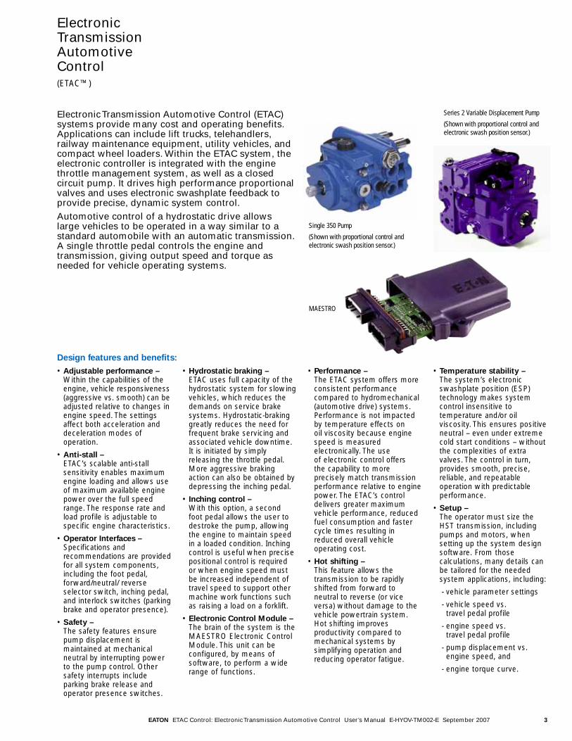
Electronic Transmission Automotive Control (ETAC)systems provide many cost and operating benefits.Applications can include lift trucks, telehandlers,railway maintenance equipment, utility vehicles, andcompact wheel loaders. Within the ETAC system, theelectronic controller is integrated with the enginethrottle management system, as well as a closedcircuit pump. It drives high performance proportionalvalves and uses electronic swashplate feedback toprovide precise, dynamic system control.Automotive control of a hydrostatic drive allowslarge vehicles to be operated in a way similar to astandard automobile with an automatic transmission.A single throttle pedal controls the engine andtransmission, giving output speed and torque asneeded for vehicle operating systems.
EATON ETAC Control: Electronic Transmission Automotive Control User’s Manual E-HYOV-TM002-E September 2007 3
• Adjustable performance –Within the capabilities of theengine, vehicle responsiveness(aggressive vs. smooth) can beadjusted relative to changes inengine speed. The settingsaffect both acceleration anddeceleration modes ofoperation.
• Anti-stall – ETAC’s scalable anti-stallsensitivity enables maximumengine loading and allows useof maximum available enginepower over the full speedrange. The response rate andload profile is adjustable tospecific engine characteristics.
• Operator Interfaces –Specifications andrecommendations are providedfor all system components,including the foot pedal,forward/neutral/ reverseselector switch, inching pedal,and interlock switches (parkingbrake and operator presence).
• Safety –The safety features ensurepump displacement ismaintained at mechanicalneutral by interrupting powerto the pump control. Othersafety interrupts includeparking brake release andoperator presence switches.
• Hydrostatic braking –ETAC uses full capacity of thehydrostatic system for slowingvehicles, which reduces thedemands on service brakesystems. Hydrostatic-brakinggreatly reduces the need forfrequent brake servicing andassociated vehicle downtime.It is initiated by simplyreleasing the throttle pedal.More aggressive brakingaction can also be obtained bydepressing the inching pedal.
• Inching control –With this option, a secondfoot pedal allows the user todestroke the pump, allowingthe engine to maintain speedin a loaded condition. Inchingcontrol is useful when precisepositional control is requiredor when engine speed mustbe increased independent oftravel speed to support othermachine work functions suchas raising a load on a forklift.
• Electronic Control Module –The brain of the system is theMAESTRO Electronic ControlModule. This unit can beconfigured, by means ofsoftware, to perform a widerange of functions.
• Performance – The ETAC system offers moreconsistent performancecompared to hydromechanical(automotive drive) systems.Performance is not impactedby temperature effects on oil viscosity because enginespeed is measuredelectronically. The use of electronic control offers the capability to moreprecisely match transmissionperformance relative to enginepower. The ETAC’s controldelivers greater maximumvehicle performance, reducedfuel consumption and fastercycle times resulting inreduced overall vehicleoperating cost.
• Hot shifting –This feature allows thetransmission to be rapidlyshifted from forward toneutral to reverse (or viceversa) without damage to thevehicle powertrain system.Hot shifting improvesproductivity compared tomechanical systems bysimplifying operation andreducing operator fatigue.
• Temperature stability – The system’s electronicswashplate position (ESP)technology makes systemcontrol insensitive totemperature and/or oilviscosity. This ensures positiveneutral – even under extremecold start conditions – withoutthe complexities of extravalves. The control in turn,provides smooth, precise,reliable, and repeatableoperation with predictableperformance.
• Setup –The operator must size theHST transmission, includingpumps and motors, whensetting up the system designsoftware. From thosecalculations, many details canbe tailored for the neededsystem applications, including:
- vehicle parameter settings
- vehicle speed vs. travel pedal profile
- engine speed vs. travel pedal profile
- pump displacement vs.engine speed, and
- engine torque curve.
Series 2 Variable Displacement Pump
(Shown with proportional control and electronic swash position sensor.)
Single 350 Pump
(Shown with proportional control and electronic swash position sensor.)
MAESTRO
Design features and benefits:
ElectronicTransmissionAutomotiveControl (ETAC™)

EATON ETAC Control: Electronic Transmission Automotive Control User’s Manual E-HYOV-TM002-E September 20074
ElectronicTransmissionAutomotiveControl (ETAC)
ETAC™
• Tailored performanceimproves productivityover a wide range ofoperator skill levels.
• ETAC™ matches enginepower to the workrequirement, for quieteroperation and reducedfuel consumption.
• Inching function maxi-mizes productivity byallowing smoother, moremanageable operation ofwork hydraulics.
• The anti-stall featureenables maximum use ofavailable engine power.
Optional ControlSystem Upgrades
Throttle Position Sensor
• Provides improved Anti-Stall Response
Cruise Control Sensor
• Provides constant pumpdisplacement whileengine speed varies
Motor Shift (Hi/Lo)
• Expands power andspeed range with inte-grated motor control.
• Choose between auto-matic or operator selec-table operation.
Key Platforms
• Compact Wheel Loaders
• Fork Lift Trucks
• Telehandlers
• Utility Vehicles
Schematic Diagram
Hi/Lo Switch(Optional)
Interlock Switch 1
Interlock Switch 2
Cruise Control Switch
(Optional)
Speed Sensor
Throttle Position or Cruise Control Sensor
(Optional)
ESP Sensor
Inching Pedal
LED Indication at Driver Panel
12 Volts DC
Maestro
Fault Indication
Light
Engine Drive Wheel
Hi/Lo Select Optional
PWM
PWM
FNR Switch
EATON ETAC Control: Electronic Transmission Automotive Control User’s Manual E-HYOV-TM002-E September 2007 5
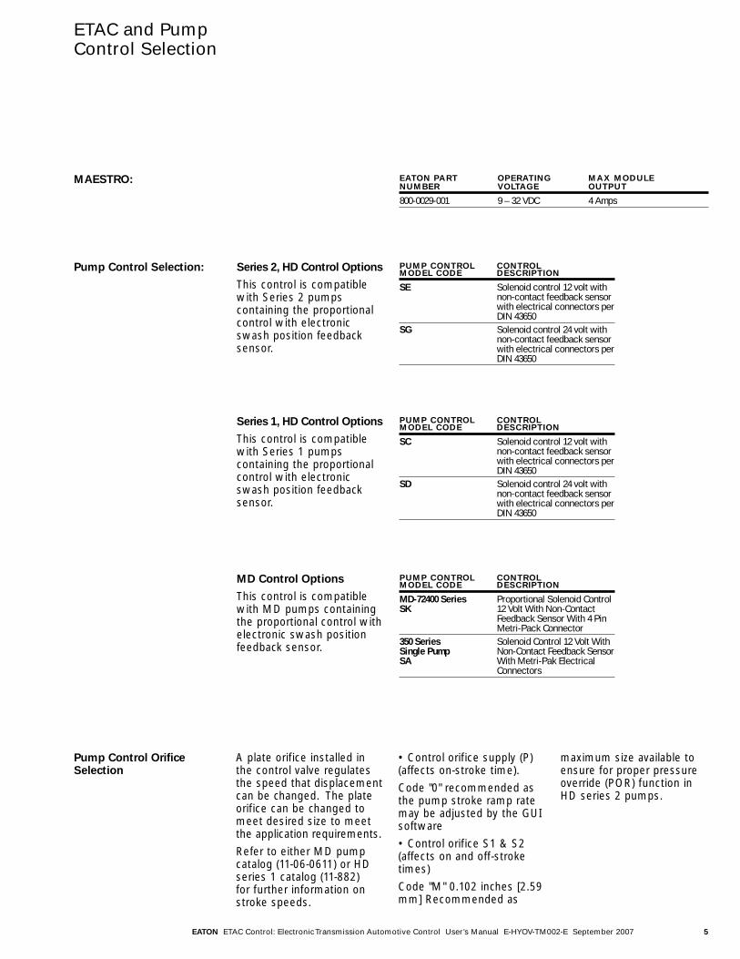
ETAC and PumpControl Selection
Series 2, HD Control Options
This control is compatiblewith Series 2 pumpscontaining the proportionalcontrol with electronicswash position feedbacksensor.
Pump Control OrificeSelection
A plate orifice installed inthe control valve regulatesthe speed that displacementcan be changed. The plateorifice can be changed tomeet desired size to meetthe application requirements.
Refer to either MD pumpcatalog (11-06-0611) or HDseries 1 catalog (11-882) for further information onstroke speeds.
• Control orifice supply (P)(affects on-stroke time).
Code "0" recommended asthe pump stroke ramp ratemay be adjusted by the GUIsoftware
• Control orifice S1 & S2(affects on and off-stroketimes)
Code "M" 0.102 inches [2.59mm] Recommended as
maximum size available toensure for proper pressureoverride (POR) function inHD series 2 pumps.
EATON PART OPERATING MAX MODULENUMBER VOLTAGE OUTPUT
800-0029-001 9 – 32 VDC 4 Amps
PUMP CONTROL CONTROLMODEL CODE DESCRIPTION
SE Solenoid control 12 volt withnon-contact feedback sensorwith electrical connectors perDIN 43650
SG Solenoid control 24 volt withnon-contact feedback sensorwith electrical connectors perDIN 43650
Series 1, HD Control Options
This control is compatiblewith Series 1 pumpscontaining the proportionalcontrol with electronicswash position feedbacksensor.
PUMP CONTROL CONTROLMODEL CODE DESCRIPTION
SC Solenoid control 12 volt withnon-contact feedback sensorwith electrical connectors perDIN 43650
SD Solenoid control 24 volt withnon-contact feedback sensorwith electrical connectors perDIN 43650
MD Control Options
This control is compatiblewith MD pumps containingthe proportional control withelectronic swash positionfeedback sensor.
PUMP CONTROL CONTROLMODEL CODE DESCRIPTION
MD-72400 Series Proportional Solenoid Control SK 12 Volt With Non-Contact
Feedback Sensor With 4 Pin Metri-Pack Connector
350 Series Solenoid Control 12 Volt WithSingle Pump Non-Contact Feedback SensorSA With Metri-Pak Electrical
Connectors
Pump Control Selection:
MAESTRO:

EATON ETAC Control: Electronic Transmission Automotive Control User’s Manual E-HYOV-TM002-E September 20076
AutodrivePerformance Curve
Note: The performance curve is adjustable by the end user thru the GUI (Graphical User Interface).
Full Displacement
Pu
mp
Dis
pla
ce
me
nt
Neutral
Max Idle RPM
Threshold RPM
Max RPM
Engine RPM
Typical AutodrivePerformance Curve

EATON ETAC Control: Electronic Transmission Automotive Control User’s Manual E-HYOV-TM002-E September 2007 7
MAESTROInstallationRequirements
• Electronic control shouldbe mounted in a "protect-ed" location. Mount themaestro in a protectedlocation keeping it frompressure washing orsteam cleaning. Mountthe MAESTRO accordingto the specifications in theinstallation drawing.Avoid locations wherevehicle wash down orexposure to "water" is likely. If the MAESTRO
is mounted in a splashlocation it is recommend-ed to orient the MAESTROwith connectors down tohelp drain away water.Leave it accessible tochange the MAESTRO ifnecessary.
• Not intended for directmounting on pump ornear the engine.
NoteMount ECM using two 1/4 inch, grade 2 bolts torqued to5.2± N m [46±5 lbf in]. Use washer with nominal O.D. of.620 or customer may use alternate bolting options ifa thread locking is employed.
The module is designed for cab mount or protected locationinstallations. Ambient temperatures are not to exceed 70°C [158°F].The module is not to be exposed to high pressure spray, steam clean or immersion conditions. If the module is mounted in asplash enviornment orient the connectors downward.
1.
2.
36.00[1.417]
2X Ø7.40[.291]
117.60[4.630]
101.60±.50[4.000±.020]
75.00[2.953]
58.03[2.285]
133.03[5.237]
60.0±.50[2.362±.020]
Sleeve Color BlackMating ConnectorDeutsch DTM06-12SB
Sleeve Color GreyMating ConnectorDeutsch DTM06-12SA
Controller Installation guidelines

EATON ETAC Control: Electronic Transmission Automotive Control User’s Manual E-HYOV-TM002-E September 20078
Connector
Connector Pin Detail
Grey Black
GREY ETAC TYPICAL ETAC TYPICALCONNECTOR PIN APPLICATION A APPLICATION B
1A ESP ESP2A Cruise Control signal Throttle pedal
(optional) (optional)3A Inching pedal Inching pedal4A FNR switch FNR switch5A FNR switch FNR switch6A Supply Supply7A Ground Ground8A CAN shield CAN shield9A Pump speed Pump speed10A Sensor Supply Sensor Supply11A CAN HI CAN HI12A CAN LO CAN LO
BLACK ETAC TYPICAL ETAC TYPICALCONNECTOR PIN APPLICATION A APPLICATION B
1B PWM Ground PWM Ground2B PWM Ground PWM Ground3B PWM Ground PWM Ground4B PWM Ground PWM Ground5B Neutral start relay6B Cruise control switch Interlock Switch 1
(optional)7B Interlock Switch 2 Interlock Switch 28B Motor speed switch Motor speed
switch (future)9B Pump coil 1 Pump coil 110B Pump coil 2 Pump coil 211B Motor speed select Motor speed
select (future)12B LED LED
Wiring Guidelines
• It is recommended to use 18AWG wire per SAE J1128
• Appropriate wiring practices should be usedfor installation to avoid abrasion, strain, damage,and EMI (electromagneticinterference). Do not routeETAC harness wires in thesame bundle as otherpower wires (example,powering motors andactuators).
• External circuits must not be connected to thesensor or solenoid wires.
• All sensor supply andground wires must bespliced together within 8 inch wire length of theMAESTRO controller. Allground wires should beconnected to a centerpoint.
• All switch supply wiresshould be spliced togetherwithin 8 inch wire lengthof the MAESTRO con-troller.
• Provide switched 12 or 24volts with a 6-amp fastblow fuse. Provide anemergency stop switch.
• As practical, route thewires in bundles andenclose the bundles insleeve material such asconvoluted tubing, meshor heat shrink tubing. Besure to choose temperatureappropriate material. This will help prevent wirefailure due to abrasion,accidental nicking or cutting.
• Avoid routing wires aroundsharp corners or roughedges. Use grommets asappropriate. Avoid makingsharp turns with the harness, for this mayincrease stresses.
• Secure the wire bundlesin channels or use wireties to secure harness to frame. Securing theharness will help preventwire fatigue and accidentaldamage from movingparts or maintenancework. Avoid long stretchesof unsupported harness.
Allow the harness tomove as the frame willmove in the application.
• Avoid high temperaturesources such as exhaustsystems and engineblocks.
• Avoid routing wires onsources of high vibration.
• When possible locate connectors shielding themfrom direct spray. Usemanufacture connectorboots, if available, to helpprevent high-pressurespray directly on a connector where thewires enter. Do not locate connectors, or wire slices,in troughs that can retainwater and leave the connector submerged inwater or other chemicals.
• Use wire routing to prevent similar connectorsfrom being mistakenlyconnected by adjustingwire length so only thecorrect connector can beengaged.
Mating Connector
Connector: Deutsch P/NDTM06-12SA, Qty. 1
Connector: Deutsch P/NDTM06-12SB, Qty. 1
Terminal: Deutsch P/N 1062-20-0122, Qty. A/R
Wedge Lock: Deutsch P/NWM-12S, Qty. 2

EATON ETAC Control: Electronic Transmission Automotive Control User’s Manual E-HYOV-TM002-E September 2007 9
Graphical UserInterface
The Graphical UserInterface (GUI) walks thesystem engineer throughthe tuning process, usingreal-time graphical feed-back to clearly indicate the system’s response to eachparameter change. Youdefine the performancecharacteristics that giveyour vehicle it’s competi-tive advantage.
The Eaton MAESTRO offersthe ability to interface withthe control for advanceddiagnostics and/or set-up ofbasic parameter settings.The GUI software P/N5995409-001 is available viadownload for installation on a PC and must be usedin conjunction with aValueCAN interface devicevia USB port connectionwith PC for control communications.
GUI Adjustable Parameters:
• EDC Module address
• Command source address
• Neutral start enable/disable
GUI User’s Guide
A detailed GUI User’s Guide may be obtained by requesting Eatondocument ATS-524.
ValueCAN Interface
Parameterization Tool
• ValueCANTM (DWCAN) interface
• Order direct from Intrepid Control Systems, Inc.
• http://www.intrepidtools.com/main/
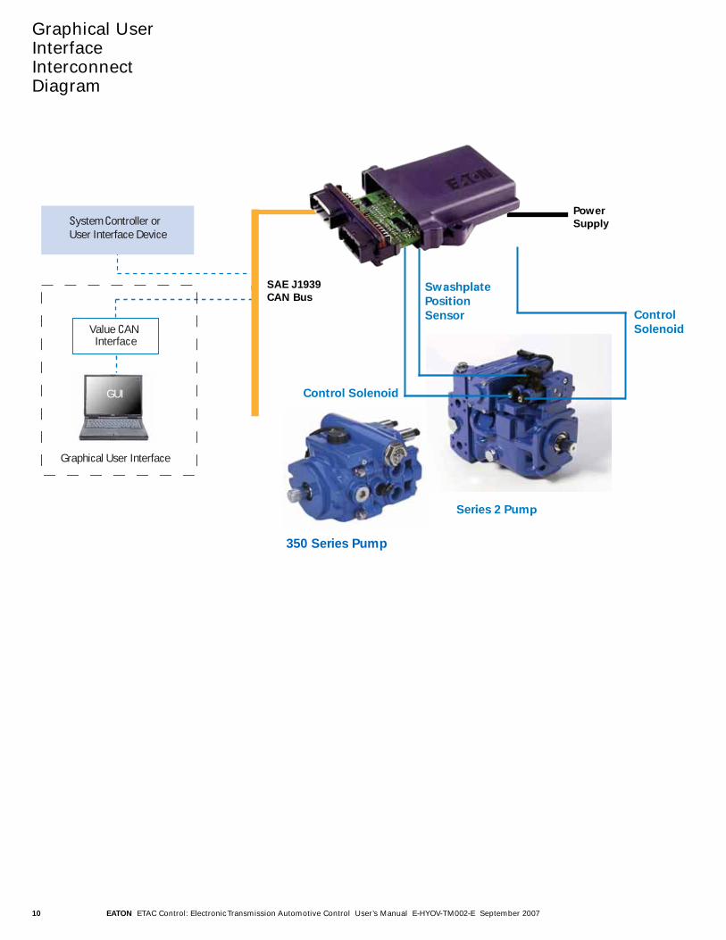
EATON ETAC Control: Electronic Transmission Automotive Control User’s Manual E-HYOV-TM002-E September 200710
Value CAN Interface
GUI
Graphical User Interface
System Controller or User Interface Device
Graphical UserInterfaceInterconnectDiagram
Power
Supply
SAE J1939
CAN Bus
CAN EDC
Series 2 Pump
Control
Solenoid
Control Solenoid
Swashplate
Position
Sensor
MAESTRO
350 Series Pump
EATON ETAC Control: Electronic Transmission Automotive Control User’s Manual E-HYOV-TM002-E September 2007 11
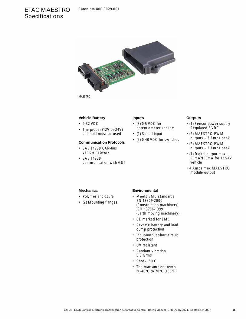
ETAC MAESTROSpecifications
Vehicle Battery
• 9-32 VDC
• The proper (12V or 24V)solenoid must be used
Communication Protocols
• SAE J1939 CAN-bus vehicle network
• SAE J1939 communication with GUI
Inputs
• (3) 0-5 VDC for potentiometer sensors
• (1) Speed input
• (5) 0-40 VDC for switches
Outputs
• (1) Sensor power supplyRegulated 5 VDC
• (2) MAESTRO PWM outputs – 3 Amps peak
• (2) MAESTRO PWM outputs – 2 Amps peak
• (1) Digital output max50mA/150mA for 12/24Vvehicle
• 4 Amps max MAESTROmodule output
Mechanical
• Polymer enclosure
• (2) Mounting flanges
Environmental
• Meets EMC standards EN 13309-2000(Construction machinery)ISO 13766-1999 (Earth moving machinery)
• CE marked for EMC
• Reverse battery and loaddump protection
• Input/output short circuitprotection
• UV resistant
• Random vibration 5.8 Grms
• Shock: 50 G
• The max ambient temp is -40°C to 70°C (158°F)
MAESTRO
Eaton p/n 800-0029-001
EATON ETAC Control: Electronic Transmission Automotive Control User’s Manual E-HYOV-TM002-E September 200712
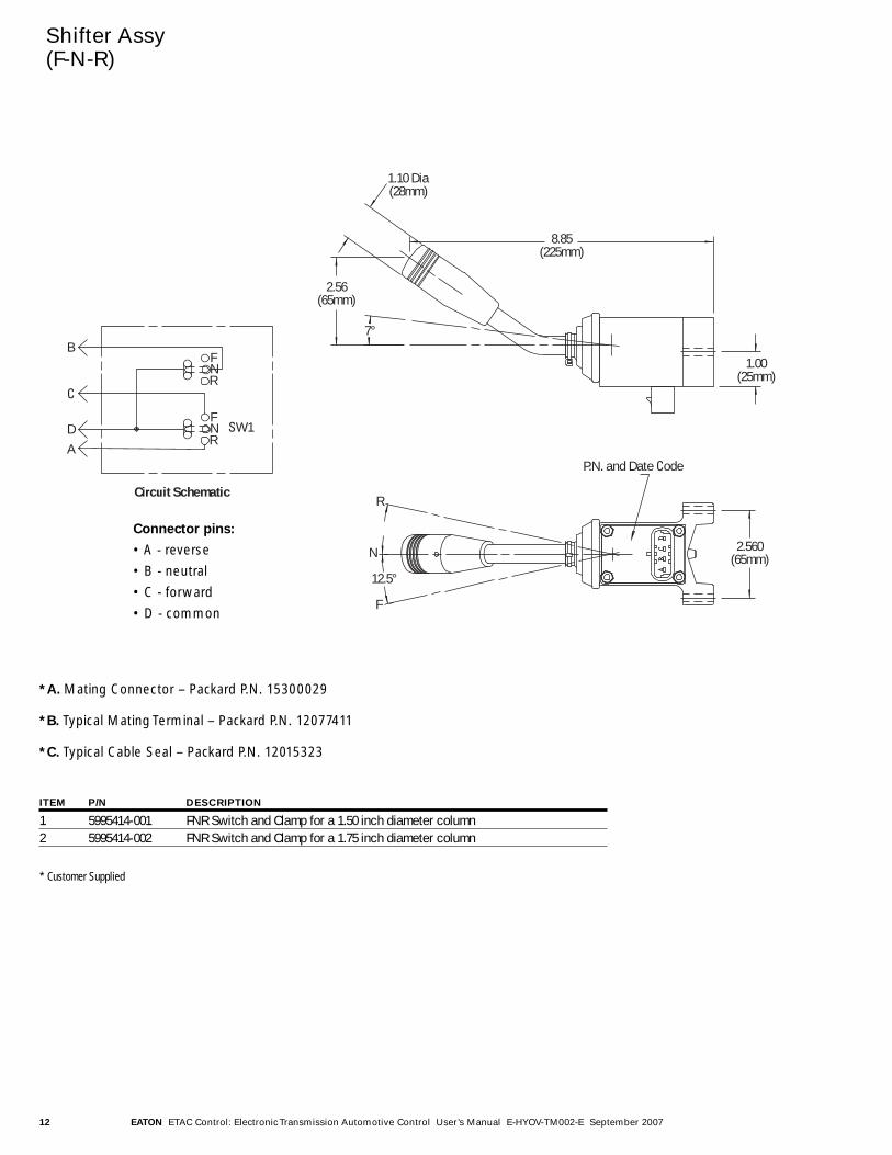
Shifter Assy (F-N-R)
Circuit Schematic
P.N. and Date Code
2.560(65mm)
R
N
F
7°
1.00(25mm)
8.85(225mm)
12.5°
1.10 Dia(28mm)
2.56(65mm)
B
C
DA
SW1FNR
FNR
*A. Mating Connector – Packard P.N. 15300029
*B. Typical Mating Terminal – Packard P.N. 12077411
*C. Typical Cable Seal – Packard P.N. 12015323
* Customer Supplied
Connector pins:
• A - reverse
• B - neutral
• C - forward
• D - common
ITEM P/N DESCRIPTION
1 5995414-001 FNR Switch and Clamp for a 1.50 inch diameter column2 5995414-002 FNR Switch and Clamp for a 1.75 inch diameter column
EATON ETAC Control: Electronic Transmission Automotive Control User’s Manual E-HYOV-TM002-E September 2007 13
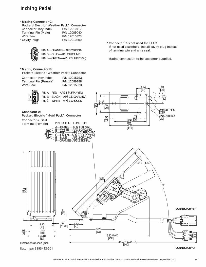
Inching Pedal
PIN COLOR FUNCTIONA---BLACK----APS 1 SIGNALB---WHITE----APS 1 GROUNDC---RED-------APS 1 SUPPLY (5V)D---GREEN---APS 2 SUPPLY (5V)E---BLUE------APS 2 GROUNDF---ORANGE--APS 2 SIGNAL
2.50[64]
1.25[32]
.63[16]
1.44[37]
.78[20]3.50
[89]4.37[111]
.50[13]
2XØ .34 THRU
2XØ .38 THRU
.97[25]
1.94[49]
[Ø10]
[Ø9]
PIN A---ORANGE---APS 2 SIGNALPIN B---BLUE---APS 2 GROUNDPIN C---GREEN---APS 2 SUPPLY (5V)
*Mating Connector B:
Packard Electric “Weather Pack”: Connector
Connector, Key Index P/N 12015793Terminal Pin (Female) P/N 12089188Wire Seal P/N 12015323
PIN A---RED---APS 1 SUPPLY (5V)PIN B---BLACK---APS 1 SIGNAL (5V) PIN C---WHITE---APS 1 GROUND
Connector, Key Index P/N 12010717 Terminal Pin (Male) P/N 12089040 Wire Seal P/N 12015323*Cavity Plug: P/N 12010300
*Mating Connector C:
Packard Electric “Weather Pack”: Connector
* Connector C is not used for ETAC. If not used elsewhere, install cavity plug instead of terminal pin and wire seal.
Connector A:
Packard Electric “Metri Pack”: Connector
Connector & SealTerminal (Female)
[81]3.20
[201]7.90
.08[2]
3.28[83]
2.70[70]
17° STROKE
9.84[250]
35°
.81[21]
[133]5.22
1.63[41]
[236]9.30 MAX
[940]37.00 1.00
.46[11.68]
CONNECTOR “B”
CONNECTOR “C”
Dimensions in inch (mm)
Eaton p/n 5995413-001
Mating connection to be customer supplied.

EATON ETAC Control: Electronic Transmission Automotive Control User’s Manual E-HYOV-TM002-E September 200714
ETAC InstallationGuidelines
• The system integratormust understand theissues of ElectromagneticCompatibility (EMC) andverify that the installationand use of the completesystem complies with allgovernmental regulations.
• Appropriate industry prac-tices must be followed toprevent damage of andshorting of electrical andelectronic componentscaused by environmentalhazards and applicationspecific hazards. Typicalhazards that damage thewiring harnesses or othercomponents are abrasion,moving objects, and heatfrom the engine orexhaust system.Moisture and/or chemicalexposure can damagepoorly sealed connectorsand/or components, caus-ing short or open circuitsand other problems likecorrosion.
• All the electrical connec-tions to the electronicmodule must be discon-nected prior to performingany electrical welding onthe vehicle or machine.The electrical module,sensors, and/or thehydraulic components arenot to be used as a con-nection point for electricalwelding equipment.
• During initial start-upand/or checkout of thesystem after service, careshould be taken to avoidthe hazards of inadvertentoperation (machine activa-tion, unintended move-ment, etc.) from improperinstallation, system prob-lems, and/or componentfailure.
• Switches need to be pro-tected from contaminationthat may cause a shortacross the switch.
General Guidelines

EATON ETAC Control: Electronic Transmission Automotive Control User’s Manual E-HYOV-TM002-E September 2007 15
ETAC DiagnosticCodes
ENGINE FNR SWITCH STATUS LIGHT NOTES
ON Forward, neutral or reverse Solid – No Fault Flashing - FaultTurn off engine and provide power to the MAESTRO to examine flash codes
OFF – MAESTRO Powered Neutral Solid – ESP Sensor in calibration Follow the ESP sensorFlashing – ESP Sensor out of calibration routine tocalibration correct this problem
OFF – MAESTRO Powered Forward Solid – No Fault See the fault codesFlashing – Fault codes will flash table for an interpretation
OFF – MAESTRO Powered Move forward to neutral to Flashing fault code will This operation clearsforward to neutral to forward cease and light will be on solid the present fault codewithin 3 seconds
Four possible faults can be displayed. The flash count determines which combinations of faults exist on the vehicle.
Fault Codes
FLASH COUNT 1 2 3 4 5 6 7 8 9 10 11 12 13 14 15
Position Fault X X X X X X X XSolenoid Fault X X X X X X X XInching Fault X X X X X X X XFNR Fault X X X X X X X X
Position Fault
Position Error – the pumpswashplate feedbackposition is not within 5degrees of the commandedswashplate position.
Neutral Range – pumpneutral position is not within2 degrees of expectedneutral.
Speed Reading – speedsensor reported enginespeed exceeds the user-defined maximum.
ESP Range – the pumpswashplate feedbackposition reading is outsidethe acceptable range.
Sensor Supply – the sensorsupply (power for the ESPSensor) is outside of itsexpected voltage range.
Solenoid Fault
Positive Solenoid Coil – thepositive coil circuit has anopen or short condition.
Negative Solenoid Coil –the negative coil circuit hasan open or short condition.
Positive Solenoid Offstate –the positive coil circuit isincapable of measuringcurrent accurately.
Negative Solenoid Offstate– the negative coil circuit isincapable of measuringcurrent accurately.
Inching Fault
Inching Pedal Range – the inching pedal positionreading is outside theacceptable range.
FNR Fault
FNR Switch – the FNRswitch Forward and Reverseinputs are reading active atthe same time.
These four fault conditions are general indicators for many possible fault conditions.

EATON ETAC Control: Electronic Transmission Automotive Control User’s Manual E-HYOV-TM002-E September 200716
Operator Interface Information:
Inching Pedal Specifications: Eaton p/n 5995413-001, 35 degree Electronic Floor Pedal Assembly without Idle Validation Switch, or equivalent. Powered by MAESTRO Controller.
FNR switch specifications: Eaton p/n
Controller Inputs for vehicle interlocks: 1. Operator presence interlock switch, for example, seat, seatbelt, roll cage (1)Please describe your operator presence interlock:
2. Parking brake interlock switch (1)
Typical ETACInstallation
ITEM P/N DESCRIPTION
1 5995414-001 FNR Switch and Clamp for a 1.50 inch diameter column2 5995414-002 FNR Switch and Clamp for a 1.75 inch diameter column
Drive Wheel
Inching Pedal
FNR Switch
Motor Speed SW
Interlock SW 1
Interlock SW 2
MAESTRO
LampCAN Bus
12V + –
FNR
E
General information, opera-tor interface devices: footpedals, joysticks, buttons,switches:
It is the customer’sresponsibility to determinethe suitability of these itemsfor the customer’s specificvehicle. Operator interfacesare electrical mechanicaldevices which have a finitelife. Only the customer canensure that appropriatevehicle design, installation,
guarding and/or fail-safedevices will protect users’safety and comply withapplicable federal, state, localand industry safety andhealth regulations, codes andstandards. We ensurecompatibility ofrecommended or equivalentproducts with the suggestedEaton electronic controllerand software configuration.We can advise of theattributes of the suggested
products and obtain testunits for prototyping.However, due to theunlimited variety ofmachines, vehicles,equipment and systemdesigns in which thesedevices may be used, it isimpossible for Eaton toguarantee the suitability of agiven operator interfacel for aspecific application.Ultimately, our customers’engineering departments
must be the qualified expertsfor their vehicle. If thesedevices will be used in asafety critical application, thecustomer must undertakeappropriate testing,evaluation, and fail safemeasures to prevent injury tothe ultimate user.
EATON ETAC Control: Electronic Transmission Automotive Control User’s Manual E-HYOV-TM002-E September 2007 17
Questionnaire:Application Data Sheet
ETAC is an electronic hydrostatic drive control which enables a vehicle to be driven in a manner similar to an automobilewith automatic transmission. Pump displacement is related to engine RPM.
ETAC is a propulsion system with anti-stall for off-road vehicles such as fork lift trucks and utility vehicles that are not equipped with boom and bucket work circuits. Inching capability is an available option which may not be needed if propulsion is the only hydraulically powered function.
Eaton Account Manager: Distributor Name:
Office Phone: Location:
Cell Phone: Distributor Salesman:
e-mail address: e-mail address:
OEM Name: Project Name:
Address: Date Prototypes Reqd:
Design Freeze Date:
Pilot Build:
Production Start Date::
OEM Engineering Contact:
Name: Production Volume:
Title: Year one:
Phone: Year two:
e-mail address: Year three:
MPS number(s):
MSS number: Mature year qty:
Vehicle Information:
Vehicle, application Description: Please provide schematics, photos, customer catalogs, etc. as availableManufacturer’s Model or Number:
Verhicle Power (battery voltage): Voltage (Vdc):
Vehicle Weight, Unloaded: Unloaded (16) kg:
Vehicle Weight, Laden: Loaded (16) kg:
Max. Weight on Drive Wheels, Front: Front lb(kg):
Max. Weight on Drive Wheels, Rear: Rear lb(kg):
Vehicle Ground Speed, Working Range: Working Range mph (kph):
Vehicle Ground Speed, Road Range: Road Range mph (kph):
Maximum Drawbar or Tractive Effort: Tractive Effort lb (kg):
Gradeability: Maximum (%):
Coefficient of Traction (adhesion): (0 -1.0)
Coefficient of Rolling Resistance: (0 -1.0)
EATON ETAC Control: Electronic Transmission Automotive Control User’s Manual E-HYOV-TM002-E September 200718
Questionnaire:Application Data Sheet
Engine Information:
Make, fuel type:
Model:
Rated power: Power hp (kW):
RPM at Rated power: (RPM)
Peak torque: Torque ft-lb (N-m):
RPM at peak torque: (RPM)
Maximum low Idle RPM: (RPM)
Maximum RPM: (RPM)
Engine performance: Please provide curve of Torque vs. Engine RPM
Drive Line Data:
Fixed drive motor displacement: Fixed (CID)cc:
Variable drive motor displacement Variable - low CID(cc):
Variable - high CID(cc):
Gearbox Ratios (if applicable): 1st gear: 3rd gear:
2nd gear: 4th gear:
Final Drive Reduction Ratio:
Wheel or Track drive:
Driven tire rolling radius: Radius inch(mm):
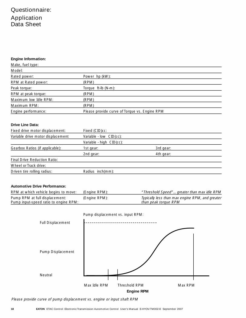
Automotive Drive Performance:
RPM at which vehicle begins to move: (Engine RPM): “Threshold Speed”…greater than max idle RPMPump RPM at full displacement: (Engine RPM): Typically less than max engine RPM, and greaterPump input-speed ratio to engine RPM: than peak torque RPM
Pump displacement vs. input RPM:
Full Displacement
Pump Displacement
Neutral
Max Idle RPM Threshold RPM Max RPM
Engine RPM
Please provide curve of pump displacement vs. engine or input shaft RPM

EATON ETAC Control: Electronic Transmission Automotive Control User’s Manual E-HYOV-TM002-E September 2007 19
© 2007 Eaton CorporationAll Rights ReservedPrinted in USADocument No. E-HYOV-TM002-ESeptember 2007
EatonHydraulics Operations USA14615 Lone Oak RoadEden Prairie, MN 55344USATel: 952-937-9800Fax: 952-294-7722www.hydraulics.eaton.com
EatonHydraulics Operations EuropeRoute de la Longeraie 71110 MorgesSwitzerlandTel: +41 (0) 21 811 4600Fax: +41 (0) 21 811 4601
EatonHydraulics Operations Asia Pacific 11th Floor Hong Kong New World Tower 300 Huaihai Zhong Road Shanghai 200021 China Tel: 86-21-6387-9988 Fax: 86-21-6335-3912