ethernet in the first mile operations, administration and ... oam tutorial v2.pdf · networks...
TRANSCRIPT

© The Metro Ethernet Forum 2005. Any reproduction of this document, or any portion thereof, shall contain the following statement: "Reproduced with permission of the Metro Ethernet Forum." No user of this document is authorized to modify any of the information contained herein.
V2.0 11/05
http://www.metroethernetforum.org Page 1
Ethernet in the First Mile Operations, Administration
and Maintenance (OAM) – A Tutorial
Overview Ethernet is well on its way to becoming a preferred broadband access technology between carrier and customer networks. It will save carriers a fortune in capital expenditures and help them deliver many times the times the bandwidth that they can today. But as its usage continues to grow in public networks, Ethernet must, as a Layer 2 protocol, be able to report network behavior at Layer 2. Predecessor carrier technologies such as SONET and ATM have long had this ability; since these protocols are still used heavily in the carrier environment, the Operations, Administration and Maintenance (OAM) designed for Ethernet must be aware of them and able to coexist with their management solutions. OAM refers to the tools and utilities to install, monitor and troubleshoot a network, helping carriers run their networks more efficiently. Without management features to monitor and troubleshoot the network, the only alternative is an expensive, time consuming truck roll, sending technicians into the field to diagnose and resolve problems on location
Ethernet Issues in Enterprise versus Carrier Environments In the enterprise, Ethernet links and networks have been managed via Simple Network Management Protocol (SNMP). Although SNMP provides a very flexible management solution, it is not always efficient and is sometimes inadequate to the task. First, using SNMP assumes that the underlying network is operational because SNMP relies on IP connectivity; however, you need management functionality even more when the underlying network is non-operational. Second, SNMP assumes every device is IP accessible. This requires provisioning IP on every device and instituting an IP overlay network even if the ultimate end-user service is an Ethernet service. This is impractical in a carrier environment. For these reasons, carriers look for management capabilities at every layer of the network. The Ethernet
layer has not traditionally offered inherent management capabilities, so the 802.3ah OAM capabilities are a first step at providing them. Note that these capabilities are not intended to replace SNMP as a management utilities, but are there to enhance it. 802.3ah OAM is applicable to all of the emerging EFM technologies:
− Ethernet in the First Mile over Copper (EFMC) − Ethernet in the First Mile over Fiber (EFMF) − Ethernet in the First Mile using Passive Optical
Networks (EPON) Network operators have the freedom to choose and mix the three EFM topologies (copper, fiber, or passive optical networking) based on their business models, network architectures, and subscriber needs. They can build or upgrade their access networks with multiple EFM topologies and manage them with a common set of tools and OAM procedures. Additionally, EFM OAM is backwards compatible with any existing full-duplex Ethernet technology, and can be implemented on non-EFM Ethernet links. This compatibility was facilitated by the decision to use standard Ethernet frames as the transport mechanism for management information.
Main Features of OAM for EFM Although EFM OAM is compatible with any Ethernet technology and can be used on even small campus networks, it is geared towards reducing expenditures for first mile operators. The main functions provided are:
− Link performance monitoring − Fault detection and fault signaling − Loopback testing
As Figure 1 shows, OAM is an optional layer implemented in the data link layer between the MAC and LLC sub-layers.

Ethernet in the First Mile Operations,
Administration and Maintenance (OAM) A Tutorial
© The Metro Ethernet Forum 2005. Any reproduction of this document, or any portion thereof, shall contain the following statement: "Reproduced with permission of the Metro Ethernet Forum." No user of this document is authorized to modify any of the information contained herein.
V2.0 11/05
http://www.metroethernetforum.org Page 2
Application
Presentation
Session
Transport
Network
Data Link
Physical
LLC-Logical Link Control or other MAC Client
OAM (Optional)
MAC Control (Optional)
MAC-Media Access Control
OSI Reference Model Layers
LAN CSMA/CD Layers
Figure 1: OSI Layers, including OAM support in
Layer 2
Since the OAM portion of 802.3ah is optional, implementers can use proprietary or existing management solutions if they choose. If they do implement OAM, they can do so in either hardware (for performance) or software (for flexibility). Also, OAM can be deployed for part of a system and does not need to be implemented system-wide. OAM can be implemented on any full duplex point to point (P2P) link or emulated P2P link. Finally, OAM can be used simultaneously with 802.3x MAC flow control PAUSE function, although when doing so PAUSE inhibits all traffic, including OAM Protocol Data Units (OAMPDUs). There is one caveat with the OAM support on gigabit links: the unidirectional fault signaling support in OAM is mutually exclusive with the auto negotiation capabilities of Gigabit Ethernet (802.3z); thus, 802.3z auto negotiation must be disabled for fault signaling to be sent over unidirectional links Note: Although the following functions are often associated with carrier management, they are not implemented in 802.3ah: • Station management • Protection switching • Provisioning and bandwidth allocation • Speed/duplex negotiation • End to end OAM communication These functions are either outside the scope of 802.3 or were not deemed suitable for Ethernet OAM.
The OAM Protocol The operation of OAM on an Ethernet interface does not adversely affect data traffic as OAM is a slow protocol with very limited bandwidth potential, and it is not required for normal link operation. This slow protocol can be implemented in hardware or software, ensuring media independence. By utilizing the slow protocol MAC address, OAM frames are intercepted by the MAC sublayer and cannot propagate across multiple hops in an Ethernet network. This implementation assures that OAMPDUs only affect the operation of the OAM protocol itself and not user data traffic. The facets of the OAM protocol discussed in this section are:
− Discovery: how OAM enabled devices discover each other and notify one another of their capabilitites
− Link monitoring: attributes and status information for Ethernet links
− Remote fault detection: how downed or compromised links are detected and handled
− Remote loopback: the testing of segments and links by sending test frames through them
− MIB variable retrieval: getting information from a management information base
− Organization specific enhancements: the provision for vendor specific enhancements to the protocol
This functionality is largely enabled through a variety of specialized OAMPDUs, which are discussed in the next section.
Discovery Discovery, the first phase of 802.3ah OAM protocol, identifies the devices in the network along with their OAM capabilities. Discovery relies on the Information OAMPDUs (discussed below). During discovery, the following information is advertised in TLVs within periodic Information OAMPDUs:
− OAM configuration (capabilities): Advertises the capabilities of the local OAM entity. With this information, a peer can determine what functions are supported and accessible, such as loopback capability.

Ethernet in the First Mile Operations,
Administration and Maintenance (OAM) A Tutorial
© The Metro Ethernet Forum 2005. Any reproduction of this document, or any portion thereof, shall contain the following statement: "Reproduced with permission of the Metro Ethernet Forum." No user of this document is authorized to modify any of the information contained herein.
V2.0 11/05
http://www.metroethernetforum.org Page 3
− OAM mode: This is conveyed to the remote OAM entity. The mode can be either active or passive, and can also be used to determine device functionality
− OAMPDU configuration: This includes maximum OAMPDU size to receipt and delivery. This information along with the rate limiting of ten frames/sec can be used to limit the bandwidth allocated to OAM traffic.
− Platform identity: The platform identity is a combination of an Organization Unique Identifier (OUI) and 32-bits of vendor specific information. OUI allocation is controlled by the IEEE and OUIs are typically the first three bytes of a MAC address.
Discovery includes an optional phase where the local station can accept or reject the configuration of the peer OAM entity. For example, a node may require that its partner support loopback capability to be accepted into the management network. These policy decisions and not specified in the standard.
Timers The protocol is driven by two timers, one which controls how frequently OAMPDUs must be sent, and one which controls how frequently OAMPDUs must be received to maintain the adjacency between devices. OAMPDUs must be sent at least once per second. When there is no other OAMPDU to be sent within a one second window, an Information OAMPDU must be sent. Similarly, OAMPDUs must be received at least once every 5 seconds . When the timer expires, the local OAM entity assumes that the remote OAM entity is non-operational and resets its state machine.
Flags Included in every OAMPDU is a flags field, which includes, among other information, the status of the discovery process. There status could be one of three possible values:
− Discovering: A discovery is in progress.
− Stable: This means that the discovery has completed. Once knowing this, the remote OAM entity can start sending any type of OAMPDU.
− Unsatisfied: When there are mismatches in OAM configuration that prevents OAM from finishing discovery, then the discovery process is unsatisfied and cannot continue.
Process Overview The discovery process allows a local Data Terminating Entity (DTE) to detect OAM on a remote DTE. Once OAM support is detected, both ends of the link exchange state and configuration information (such as mode, PDU size, loopback support, etc.). If both DTEs are satisfied with the settings, OAM is enabled on the link. However, the loss of a link or a failure to receive OAMPDUs for five seconds may cause the discovery process to restart. DTEs may either be in active or passive mode. Active mode DTEs instigate OAM communications and can issue queries and commands to a remote device. Passive mode DTEs generally wait for the peer device to instigate OAM communications and respond to, but do not instigate, commands and queries. Rules for what DTEs in active or passive mode can do are discussed in the following sections.
Rules for Active A DTE in Active mode: − Initiates the OAM Discovery process − Sends Information PDUs − May send Event Notification PDUs − May send Variable Request/Response PDUs − May send Loopback Control PDUs
Exceptions to this are: − Does not respond to Variable Request PDUs from
DTEs in Passive mode − Does not react to Loopback Control PDUs from
DTEs in Passive mode − They can identify the platforms − You can make policy decisions on whether to
allow peering (for instance, this might determine whether you would support loopback)
Ethernet in the First Mile Operations,
Administration and Maintenance (OAM) A Tutorial
© The Metro Ethernet Forum 2005. Any reproduction of this document, or any portion thereof, shall contain the following statement: "Reproduced with permission of the Metro Ethernet Forum." No user of this document is authorized to modify any of the information contained herein.
V2.0 11/05
http://www.metroethernetforum.org Page 4
Rules for Passive A DTE in Passive mode:
− Waits for the remote device to initiate the Discovery process
− Sends Information PDUs − May send Event Notification PDUs − May respond to Variable Request PDUs − May react to received Loopback Control PDUs − Is not permitted to send Variable Request or
Loopback Control OAMPDUs
Link Monitoring Link monitoring tools are for detecting and indicating link faults under a variety of circumstances. Link monitoring uses the Event Notification OAMPDU, and sends events to the remote OAM entity when there are problems detected on the link. The error events defined in the standard are:
− Errored Symbol Period (errored symbols per second): the number of symbol errors that occurred during a specified period exceeded a threshold. These are coding symbol errors (for example, a violation of 4B/5B coding).
− Errored Frame (errored frames per second): the number of frame errors detected during a specified period exceeded a threshold.
− Errored Frame Period (errored frames per N frames): the number of frame errors within the last N frames has exceeded a threshold.
− Errored Frame Seconds Summary (errored secs per M seconds): the number of errored seconds (one second intervals with at least one frame error) within the last M seconds has exceeded a threshold.
Since 802.3ah OAM does not provide a guaranteed delivery of any OAMPDU, the Event Notification OAMPDU (discussed in the OAMPDU section below) can be sent multiple times to reduce the probability of a lost notification. A sequence number is used to recognize duplicate events.
Remote Failure Indication Faults in Ethernet are difficult to detect, especially when caused by slowly deteriorating quality rather than completely disconnected links. A flag in the OAMPDU
allows an OAM entity to convey failure conditions to its peer. The failure conditions are as follows:
− Link Fault: Loss of signal is detected by the receiver; this is sent once per second in the Information OAMPDU
− Dying Gasp: Unrecoverable condition (e.g., a power failure) has occurred; these may be sent immediately and continuously
− Critical Event: Unspecified critical event has occurred; these may also be sent immediately and continuously
Conditions for dying gasp and critical event are left to implementers. The unrecoverable condition for dying gasp could be interpreted as any condition that causes the equipment to restart. The link fault applies only when the physical sub-layer is capable of independent transmit and receive. When a link is not receiving a signal from its peer at the physical layer (for example, if the peer’s laser was malfunctioning), the local entity can set this flag to let the peer know that its transmit path is inoperable. The above conditions are severe, thus when they are set in the flag, the OAMPDU is not subject to normal rate limiting policy.
Remote Loopback An OAM entity can put its remote entity into loopback mode using a loopback control OAMPDU. This helps you ensure the quality of links during installation or when troubleshooting. In loopback mode, every frame received is transmitted back on that same port except for OAMPDUs and pause frames. The periodic exchange of OAMPDUs must continue during loopback state to maintain the OAM session. The loopback command is acknowledged by responding with an Information OAMPDU with the loopback state indicated in the state field. This allows you, for instance, to estimate if a network segment can satisfy an SLA. You can test delay, jitter and throughput (implementations for these tests will be vendor specific).

Ethernet in the First Mile Operations,
Administration and Maintenance (OAM) A Tutorial
© The Metro Ethernet Forum 2005. Any reproduction of this document, or any portion thereof, shall contain the following statement: "Reproduced with permission of the Metro Ethernet Forum." No user of this document is authorized to modify any of the information contained herein.
V2.0 11/05
http://www.metroethernetforum.org Page 5
MIB Variable Retrieval A MIB (Management Information Base) is a database of manageable variables; OAM provides a read-only access remote MIB variables limited to a specific MIB branch and leaf. The request-response nature of variable retrieval can also be used to implement measurement functions for estimating the link capability to support an SLA (similar to IP ping for measuring delay, jitter and throughput). This assumes that the time accessing the variable is negligible compared to propagation and queuing delay of the request and response. Note: Only the retrieval of MIB variables is supported in 802.3ah OAM; you cannot set MIB variables.
Organization Specific Extensions Organization extensions are available through organization specific OAMPDUs and organization specific TLVs within the standard OAMPDUs. These extensions carry an Organization Unique Identifier (OUI) in the frame to indicate the designator of the extension. Vendors can use these extensions to implement extra events, to include additional information during discovery, or even to add a completely proprietary OAM protocol.
OAM Protocol Data Units As stated above, the architecture of the OAM protocol is based on OAM protocol data units (OAMPDU), which are exchanged between two Ethernet ports. OAMPDUs are normal Ethernet frames that use a specific multicast destination address and EtherType. Characteristics of OAMPDUs, and the OAMPDUs themselves, are discussed in the following sections.
OAMPDU Characteristics This section discusses the unidirectional nature of OAMPDUs, as well as the size/rates of OAMPDUs and the Flags fields.
Unidirectional Nature Ethernet has historically had the behavior that when one direction of communication fails on a link, the other direction of the link is taken down. This was done to eliminate the possibility of one-way transmissions, so that higher layer protocols don’t have to deal with that error scenario. With EFM OAM, however, certain physical layers can support a limited unidirectional capability. Legacy links indeed become inoperable when one direction fails, but newer links (such as 100BASE-X PCS, 1000BASE-X PCS, and 10GbE RS) can still send OAMPDUs unidirectionally to transmit fault information. On technologies that support the feature, OAMPDUs can be transmitted across unidirectional links to indicate fault information. To the higher layers, the link is still failed in both directions, but to the OAM layer, some communication capabilities exist. The distinction between a unidirectional link and a “normal” link is shown in Figure 2.
Data frames & Data frames & OAMPDUs sent OAMPDUs sent
in in bothbothdirectionsdirections
Only Only OAMPDUs OAMPDUs sent in sent in oneonedirectiondirection
Unidirectional Unidirectional linklink
Normal linkNormal link
XX
Figure 2: OAMPDUs Transmitted over
Unidirectional Link
As Figure 3 shows, OAMPDUs only traverse a single link; they are not forwarded by bridges. Communication beyond a single link is left to higher layers.

Ethernet in the First Mile Operations,
Administration and Maintenance (OAM) A Tutorial
© The Metro Ethernet Forum 2005. Any reproduction of this document, or any portion thereof, shall contain the following statement: "Reproduced with permission of the Metro Ethernet Forum." No user of this document is authorized to modify any of the information contained herein.
V2.0 11/05
http://www.metroethernetforum.org Page 6
OAMPDUs
OAMPDUs
OAMPDUs
Figure 3: OAMPDUs are Single-Link Only
Size/Rate OAMPDUs are standard length Ethernet frames; they must be untagged and within the normal frame length boundaries of 64 to 1518 bytes in length; the format is shown in Figure 4. The maximum PDU size is determined during the discovery process.
01-80-c2-00-00-02 [Slow Protocol]MAC Source AddressType=88-09 [Slow Protocols]
Subtype = 0x03 [OAM]Flags field
OctetsOctets
66
66
22
11
22
4242--14961496 Data/Pad fieldFrame Check Sequence44
6464--15181518
Code11
Figure 4: Format of OAMPDU
In Figure 5, you see the different OAMPDUs detailed, according to the contents of the code and data/pad fields.
Figure 5: Codes and Data/Pad Contents for the
Various OAMPDUs
There is a maximum transmission rate of ten OAMPDUs per second (This is the maximum rate as defined in Annex 43B as modified by 802.3ah) In order to increase the likelihood (in high BER conditions) that OAMPDUs will be received by a remote device, some OAMPDUs may be sent multiple times
Flags A two byte flags field contains the discovery status of local and remote OAM entities, as well as fault indications. Figure 6illustrates the possible contents of the Flags field.
Figure 6: Flags Field
As discussed above, the Flags field indicates critical fault events, which may include link fault, dying gasp, or critical event.

Ethernet in the First Mile Operations,
Administration and Maintenance (OAM) A Tutorial
© The Metro Ethernet Forum 2005. Any reproduction of this document, or any portion thereof, shall contain the following statement: "Reproduced with permission of the Metro Ethernet Forum." No user of this document is authorized to modify any of the information contained herein.
V2.0 11/05
http://www.metroethernetforum.org Page 7
Overview of OAMPDU Types There are six types of OAMPDU (see the following table): information, event notification, variable request, variable response, loopback control and organization specific. OAMPDU Type
Code Length Usage
Information 0x00 Varies Discovery Event Notification
0x01 Varies Link monitoring and any other events
Variable Request
0x02 Varies Get MIB variable(s)
Variable Response
0x03 Varies Return MIB variable(s)
Loopback Control
0x04 64 octets
Control remote loopback state
Reserved 0x05 to 0xFD
Organization Specific
0xFE Varies Miscellaneous use
Reserved 0xFF Most of the OAMPDU types also define a set of standard type-length-value (TLV) encoding of attributes within the type. Note: Unknown/unsupported OAMPDUs are sent to the OAM client. This is different from typical Ethernet (802.3x) behavior, which filtered unsupported opcodes. More detail on these OAMPDUs is provided in the following sections.
Information OAMPDU Information OAMPDUs are used for discovery; they are variable-length OAMPDUs and use the code 0x00. The different TLVs for Information PDUs are local information, remote information, and organization specific. Figure 7 illustrates these TLVs.
Destination Address
Source Address
Length/Type
Subtype
Flags
Code
Data/Pad
FCS
42-1496
4
1
2
2
1
6
6 01-80-c2-00-00-02
88-09
0x03
0x01
Octets Fields Fixed Values
Octets Fields
INFORMATIONOAMPDU
LOCAL INFORMATION TLV
REMOTE INFORMATION TLV
ORGANIZATION SPECIFIC
INFORMATION TLV
Fixed Values
0x00
Information Type1
Information Length1
OAM Version1
Revision2
State1OAM Configuration1
OAMPDU Configuration2OUI3Vendor Specific Information4
0x10
0x01
0x01
Information Type1
Information Length1OAM Version1
Revision2
State1OAM Configuration1
OAMPDU Configuration2OUI3Vendor Specific Information4
0x100x01
0x01
Information Type1
Information Length1OUI1
2 Organization Specific Value
0x01
0x02
0xFE
Figure 7: Information PDU
Local and remote information is used in the discovery process. The Organization Specific Information TLV is used for vendor extensions. It is encoded here because the source MAC address is not a simple indication of organization identification as many organizations have multiple OUIs assigned. The 32-bit vendor specific information is not defined and is used to encode the model or version of the platform. The platform identity field is intended to allow simple identification of the hardware device. The following table summarizes the TLVs in the Information OAMPDU. Information Type Information TLV Name 0x00 End of TLV Marker 0x01 Local Information 0x02 Remote Information 0x03 – 0xFD Reserved 0xFE Organization Specific Information 0xFF Reserved
A more detailed breakdown of the Informational OAMPDU for Local/Remote Information follows

Ethernet in the First Mile Operations,
Administration and Maintenance (OAM) A Tutorial
© The Metro Ethernet Forum 2005. Any reproduction of this document, or any portion thereof, shall contain the following statement: "Reproduced with permission of the Metro Ethernet Forum." No user of this document is authorized to modify any of the information contained herein.
V2.0 11/05
http://www.metroethernetforum.org Page 8
Figure 8: Local/Remote Information in the
Information OAMPDU
Event Notification OAMPDU The data field in the Event Notification OAMPDU contains one or more link event TLVs. This variable-length PDU is used for link monitoring. The OAM Link Event TLVs are summarized in the following table. Event Type Event TLV Name 0x00 End of TLV Marker 0x01 Errored Symbol Period Event 0x02 Errored Frame Event 0x03 Errored Frame Period Event 0x04 Errored Frame Seconds Summary Event 0x05 – 0xFD Reserved 0xFE Organization Specific Event TLV 0xFF Reserved These may be sent multiple times to increase the likelihood of reception (for example, in the case of high bit errors). These TLVs may include a time reference when generated. On a field level, the Event Notification OAMPDUs are shown in Figure 9.
Destination Address
Source Address
Length/Type
Subtype
Flags
Code
Data/Pad
FCS
42-1496
4
1
2
2
1
6
6 01-80-c2-00-00-02
88-09
0x03
Event Type1
Octets Fields Fixed Values
Octets Fields
EVENT NOTIFICATION
OAMPDU
ERRORED FRAME SECONDS SUMMARY EVENT
Fixed Value
s
0x01
Event Length1Event Time Stamp2Errored Symbol Window8Errored Symbol Threshold8Errored Symbols8Error Running Total8Event Running Total4
Event Type1Event Length1Event Time Stamp2Errored Frame Window2Errored Frame Threshold4Errored Frames4Error Running Total8Event Running Total4
Event Type1Event Length1Event Time Stamp2Errored Frame Window4Errored Frame Threshold4Errored Frames4Error Running Total8Event Running Total4
Event Type1Event Length1Event Time Stamp2Err.Fr.Sec.Sum. Window2Err.Fr.Sec.Sum. Threshold2Err.Fr.Sec.Summary2Error Running Total4Event Running Total4
Event Type1Event Length1OUI3Organization Specific Valuex
Sequence Number2SEQUENCE NUMBER
ERRORED SYMBOL PERIOD EVENT
ERRORED FRAME EVENT
ORGANIZATION SPECIFIC EVENT
ERRORED FRAME PERIOD EVENT
0x01
0x02
0x03
0x04
0xFE
0x28
0x1A
0x1C
0x12
Figure 9: Event Notification OAMPDU
These are discussed in more detail in the following sections.
Figure 10: Errored Symbol Period Event TLV (Link
Event Notification OAMPDU)

Ethernet in the First Mile Operations,
Administration and Maintenance (OAM) A Tutorial
© The Metro Ethernet Forum 2005. Any reproduction of this document, or any portion thereof, shall contain the following statement: "Reproduced with permission of the Metro Ethernet Forum." No user of this document is authorized to modify any of the information contained herein.
V2.0 11/05
http://www.metroethernetforum.org Page 9
The errored symbol period event is a window, measured in number of symbols, where the number of errored symbols exceeded a threshold. As Figure 10 shows, this is a 40 octet TLV. The following table shows the potential values of these octets. Fields Width Description Timestamp 16 bits Time reference, in 100 ms
units, when generated Window 64 bits Lower bound: Symbols in
one second Upper bound: Symbols in 60 seconds
Threshold 64 bits Lower bound: 0 Upper bound: Unspecified
Errors 64 bits Number of symbols errors in Window field
Total Errors 64 bits Total number of symbol errors since reset
Total Errors 32 bits Total number of events sent since reset
Errored Frame Event TLV The Errored Frame Event TLV is a window, measured in 100 ms intervals, where the number of errored frames exceeds a threshold. This is a 26 octet TLV. Its fields are described in the following table. Fields Width Description Timestamp 16 bits Time reference, in 100 ms
units, when generated Window 16 bits Lower bound: 1 second
Upper bound: 60 seconds Threshold 32 bits Lower bound: 0
Upper bound: Unspecified Errors 32 bits Number of frame errors in
Window field
Total Errors 64 bits Total number of frame errors since reset
Total Errors 32 bits Total number of events sent since reset
Errored Frame Period Event TLV The Errored Frame Period Event TLV is a window, measured in received frames, where the number of errored frames exceeded a threshold. This is a 28 octet TLV. Its fields are described in the following table. Fields Width Description Timestamp 16 bits Time reference, in 100 ms
units, when generated Window 32 bits Lower bound: number of
64 byte frames in one second Upper bound: number of 64 byte frames in 60 seconds
Threshold 32 bits Lower bound: 0 Upper bound: Unspecified
Errors 32 bits Number of frame errors in Window field
Total Errors 64 bits Total number of frame errors since reset
Total Errors 32 bits Total number of events sent since reset
Errored Frame Seconds Summary TLV The errored frame seconds summary is a window, in 100ms intervals, where the number of errored frames exceeded a threshold. This is a 22 octet TLV. Its fields are described in the following table.
Fields Width Description Timestamp 16 bits Time reference, in 100 ms
units, when generated Window 16 bits Lower bound: 10 seconds
Upper bound: 900 seconds
Threshold 16 bits Lower bound: 0 Upper bound: Unspecified
Errors 16 bits Number of frame errors in Window field
Total Errors 64 bits Total number of errors caused since reset
Total Events 32 bits Total number of events sent since reset
Ethernet in the First Mile Operations,
Administration and Maintenance (OAM) A Tutorial
© The Metro Ethernet Forum 2005. Any reproduction of this document, or any portion thereof, shall contain the following statement: "Reproduced with permission of the Metro Ethernet Forum." No user of this document is authorized to modify any of the information contained herein.
V2.0 11/05
http://www.metroethernetforum.org Page 10
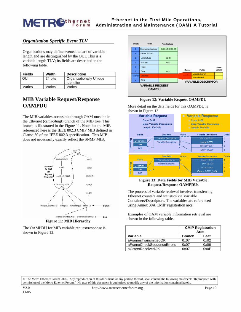
Organization Specific Event TLV Organizations may define events that are of variable length and are distinguished by the OUI. This is a variable length TLV; its fields are described in the following table. Fields Width Description OUI 24 bits Organizationally Unique
Identifier Varies Varies Varies
MIB Variable Request/Response OAMPDU The MIB variables accessible through OAM must be in the Ethernet (csmacdmgt) branch of the MIB tree. This branch is illustrated in the Figure 11. Note that the MIB referenced here is the IEEE 802.3 CMIP MIB defined in Clause 30 of the IEEE 802.3 specification. This MIB does not necessarily exactly reflect the SNMP MIB.
Figure 11: MIB Hierarchy
The OAMPDU for MIB variable request/response is shown in Figure 12.
Destination Address
Source Address
Length/Type
Subtype
Flags
Code
Data/Pad
FCS
42-1496
4
1
2
2
1
6
6 01-80-c2-00-00-02
88-09
0x03
Octets Fields Fixed Values
Octets Fields
VARIABLE REQUEST OAMPDU
VARIABLE DESCRIPTOR
Fixed Values
0x02Variable Branch1
Variable Leaf1
Destination Address
Source Address
Length/Type
Subtype
Flags
Code
Data/Pad
FCS
42-1496
4
1
2
2
1
6
6 01-80-c2-00-00-02
88-09
0x03
Octets Fields Fixed Values
Octets Fields
VARIABLE REQUEST OAMPDU
VARIABLE DESCRIPTOR
Fixed Values
0x02Variable Branch1
Variable Leaf1
Figure 12: Variable Request OAMPDU
More detail on the data fields for this OAMPDU is shown in Figure 13.
Figure 13: Data Fields for MIB Variable
Request/Response OAMPDUs
The process of variable retrieval involves transferring Ethernet counters and statistics via Variable Containers/Descriptors. The variables are referenced using Annex 30A CMIP registration arcs. Examples of OAM variable information retrieval are shown in the following table. CMIP Registration
Arcs Variable Branch Leaf aFramesTransmittedOK 0x07 0x02 aFrameCheckSequenceErrors 0x07 0x06 aOctetsReceivedOK 0x07 0x0E

Ethernet in the First Mile Operations,
Administration and Maintenance (OAM) A Tutorial
© The Metro Ethernet Forum 2005. Any reproduction of this document, or any portion thereof, shall contain the following statement: "Reproduced with permission of the Metro Ethernet Forum." No user of this document is authorized to modify any of the information contained herein.
V2.0 11/05
http://www.metroethernetforum.org Page 11
Loopback Control OAMPDU The Loopback Control OAMPDU provides the loopback command. It is illustrated in Figure 14
Destination Address
Source Address
Length/Type
Subtype
Flags
Code
Data/Pad
FCS
1 + 41
4
1
2
2
1
6
6 01-80-c2-00-00-02
88-09
0x03
Octets Fields Fixed Values
LOOPBACK CONTROL OAMPDU
0x04
Octets Fields
ENABLE REMOTE LOOPBACK COMMAND
Fixed Values
Remote Loopback Command1
DISABLE REMOTE LOOPBACK COMMAND
Remote Loopback Command1 0x02
0x01
Figure 14: Loopback Control OAMPDU
The Loopback Command OAMPDU is 64 octets. You can enable or disable a loopback using this OAMPDU.
OAM Remote Loopback In remote loopback, the local DTE sends a Loopback Control OAMPDU requesting the remote end to go into loopback mode until it is turned off. The local DTE sends arbitrary data frames, and the remote DTE returns them. Note: When the BER is better than one error 10 ** -6 bits, there is a high probability that the frame error rate is equal to the bit error rate. Remote loopback, which can be implemented in either hardware or software, is illustrated in Figure 15. Frames are discarded at the local side when received back.
Figure 15: Remote Loopback
The OAM Sublayer Loopback functionality is best understood in terms of the OAM sublayer. A block diagram of this sublayer is shown in Figure 16
Control
Multiplexer Parser
Physical Layer
MAC clientOAM client
MAC-Media Access Control
MAC Control (Optional)
OAM_CTL.request
OAM_CTL.indication
OAMPDU.request
OAMPDU.indication
MCF:MA_DATA.request
MCF:MA_DATA.indication
802.3 MAC dataService interface
802.3 MAC dataService interface
802.3 OAM clientService interface
MAC:MA_DATA.request MAC:MA_DATA.indication
OAMPDUs
MAC client frames
CTL:OAMI.request
CTL:OAMI.indication
Loopbackframes
Control
MultiplexerMultiplexer ParserParser
Physical Layer
MAC clientOAM client
MAC-Media Access Control
MAC Control (Optional)
OAM_CTL.request
OAM_CTL.indication
OAMPDU.request
OAMPDU.indication
MCF:MA_DATA.request
MCF:MA_DATA.indication
802.3 MAC dataService interface
802.3 MAC dataService interface
802.3 OAM clientService interface
MAC:MA_DATA.request MAC:MA_DATA.indication
OAMPDUs
MAC client frames
CTL:OAMI.request
CTL:OAMI.indication
Loopbackframes
Figure 16: OAM Sublayer

Ethernet in the First Mile Operations,
Administration and Maintenance (OAM) A Tutorial
© The Metro Ethernet Forum 2005. Any reproduction of this document, or any portion thereof, shall contain the following statement: "Reproduced with permission of the Metro Ethernet Forum." No user of this document is authorized to modify any of the information contained herein.
V2.0 11/05
http://www.metroethernetforum.org Page 12
The OAM sublayer consists of a MAC and OAM client, a control plane, a multiplexer, and a parser. These components are described in the following table. Component Function MAC client 802.3 MAC data is sent to the multiplexer
and received from the parser OAM client • Configures OAM sublayer through
Control • Processes received OAMPDUs • Transmits PDUs
Control Provides interface with OAM client entity Parser
• Inspects received frames, sends OAMPDUs to Control (and then to OAM client)
• Based on configuration, sends: o Non-OAMPDUs to upper layer,
or o Non-OAMPDUs to multiplexer
Multiplexer Multiplexes PDUs and non-PDUs
Starting and Exiting Remote Loopback Figure 1 illustrates the OAM algorithm for starting a remote loopback. The local DTE stops sending data frames and sends a Loopback Control OAMPDU to the remote DTE, which configures the parser to “loopback” and sends an Information OAMPDU back to the local site. Then the local DTE starts sending loopback frames.
Figure 17: Starting Remote Loopback
The process of exiting remote loopback, illustrated in Figure 18, begins with the local DTE stopping the transmission of loopback frames.
Figure 18: Exiting Remote Loopback
Organization Specific OAMPDU There is an organization specific code that allows specific extensions. When this code (0xFE) is used, and organizationally unique identifier OUI is specified in the data field, and the contents of the rest of the data field is defined by the organization that owns the OUI. Figure 19 illustrates this support.
Destination Address
Source Address
Length/Type
Subtype
Flags
Code
Data/Pad
FCS
42-1496
4
1
2
2
1
6
6 01-80-c2-00-00-02
88-09
0x03
Octets Fields Fixed Values
ORGANIZATION SPECIFIC OAMPDU
0xFE
Octets FieldsFixed
Values
OUI3
ORGANIZATION SPECIFIC
Destination Address
Source Address
Length/Type
Subtype
Flags
Code
Data/Pad
FCS
42-1496
4
1
2
2
1
6
6 01-80-c2-00-00-02
88-09
0x03
Octets Fields Fixed Values
ORGANIZATION SPECIFIC OAMPDU
0xFE
Octets FieldsFixed
Values
OUI3
ORGANIZATION SPECIFIC
Figure 19: Organization-Specific OAMPDU
Conclusion OAM is implemented as a sublayer at Layer 2. It supports the most critical management functionality needed in the first mile: fault detection and troubleshooting. The OAMPDUs report events, allow the retrieval of variables, and support loopbacks for troubleshooting.

Ethernet in the First Mile Operations,
Administration and Maintenance (OAM) A Tutorial
© The Metro Ethernet Forum 2005. Any reproduction of this document, or any portion thereof, shall contain the following statement: "Reproduced with permission of the Metro Ethernet Forum." No user of this document is authorized to modify any of the information contained herein.
V2.0 11/05
http://www.metroethernetforum.org Page 13
Appendix Terminology
Term Definition Access Node
The network side of the first mile where an operator's access equipment is located. Options exist to deploy the Access Node in a Central Office (Telephony Local Exchange) or remotely at the curbside or in a building.
CWDM Coarse Wave Division Multiplexing Ethernet A packet-based protocol that is used
universally in local area networks and strong candidate for cost efficient deployment in access and metropolitan networks.
EFMC Ethernet in First Mile topology for voice-grade copper.
EFMF Ethernet in First Mile using Point-to-Point Fiber topology
EFMP Etehrnet in First Mile using Point-to-Multipoint topology, based on Passive Optical Networks (PONs).
EFMA Ethernet in First Mile Alliance. An alliance of companies whose goal is to focus the necessary resources to make IEEE 802.3ah a successful industry standard. In 2004, the EFMA became part of the Metro Ethernet Forum
FTTB Fiber to the building FTTC Fiber to the curb FTTH Fiber to the home First Mile
Also called the last mile, the subscriber access network or the local loop, the first mile is the communications infrastructure of the business park or the neighborhood.
IEEE Institute of Electrical and Electronics Engineers. A standards setting body responsible for many telecom and computing standards, including the Ethernet in the First Mile standard, IEEE 802.3ah.
MDU Multi-dwelling unit, such as an apartment house or hotel.
MTU Multi-tenant units, such as an apartment house or office building.
OAM The specification for managing EFM. Network operator
Also called service providers and local exchange carriers, they provide access network services to subscribers.
PON Passive Optical Network. A single, shared optical fiber that has inexpensive optical splitters located near the subscribers.
PMD Physical Media Dependent sub-layer PHY Physical Layer PSTN Public Switched Telephone Network.
References and Resources Reference Description
IEEE 802.3-2002
“CSMA/CD Access Method and Physical Layer Specifications”, http://standards.ieee.org/reading/ieee/std/lanman/restricted/802.3-2002.pdf
IEEE 802.1Q “Virtual Bridged Local Area Networks”, http://standards.ieee.org/reading/ieee/std/lanman/802.1Q-1998.pdf
MEF 10
MEF Technical Specification “Ethernet Service Attributes, Phase 1”, http://www.metroethernetforum.org/PDFs/Standards/MEF10.pdf
MEN Technical Overview
“ Metro Ethernet Networks – A Technical Overview”, http://www.metroethernetforum.org/PDFs/WhitePapers/metro-ethernet-networks.pdf
Disclaimer This paper reflects ongoing work within the MEF captured in a series of technical specifications which are a work in progress. The official MEF specifications are available at www.metroethernetforum.com/techspec. These represent a 75% member majority consensus as voted by members of the MEF Technical Committee at the time of their adoption. This paper will be updated as new work emerges from the MEF Technical Committee. Updates versions are available at http://www.metroethernetforum.org .
About the Metro Ethernet Forum The Metro Ethernet Forum (MEF) is a non-profit organization dedicated to accelerating the adoption of optical Ethernet as the technology of choice in metro networks worldwide. The Forum is comprised of leading service providers, major incumbent local exchange carriers, top network equipment vendors and other prominent networking companies that share an interest in metro Ethernet. As of December 2005, the MEF had over 70 members