ethernet/ip™ compatible si unit instruction manual · pdf filereduced wiring system...
TRANSCRIPT

Reduced wiring system
EX250-SEN1
Instruction ManualEtherNet/IP™ Compatible SI Unit
URL http://www.smcworld.com
Specifications are subject to change without prior notice and any obligation on the part of the manufacturer.EtherNet/IP™ is a trademark used under licence by ODVA.The descriptions of products shown in this document may be used by the other companies as their trademarks.© 2006 SMC Corporation All Rights Reserved

ContentsThank you for purchasing the SMC reduced wiring system EX250 series.
Please read this instruction manual carefully and understand the contents before
use so that you can operate this unit safely and correctly.
Please keep this manual handy for future reference.
OPERATORThis instruction manual has been written for those who have knowledge of
machines and equipments that use reduced wiring system as well as the
sufficient knowledge to assemble, operate, and maintain such devices.
Before performing assembly, operation and/or maintenance, please read
this manual carefully and understand the contents.
To facilitate recycling, thismanual is printed usingbiodegradable soy ink, whichcan easily be de-inked.
This manual is printed in the"non-water system", which doesnot output toxic liquid waste.
SAFETY ..........................................................................................................2
Product Summary............................................................................................5
SI Unit
Model Indication Method...............................................................................6
Part Names ...................................................................................................6
Dimensions ...................................................................................................7
Mounting/Installation .....................................................................................7
Specifications..............................................................................................10
Wiring..........................................................................................................12
Display/Setting ............................................................................................15
Input Block
Model Indication Method.............................................................................18
Part Names .................................................................................................18
Dimensions .................................................................................................19
Mounting/Installation ...................................................................................19
Specifications..............................................................................................19
Wiring..........................................................................................................20
Display/Setting ............................................................................................22
EX9 Series Output Block/Power Block
Model Indication Method.............................................................................23
Part Names .................................................................................................24
Dimensions .................................................................................................25
Mounting/Installation ...................................................................................25
Specifications..............................................................................................25
Wiring .........................................................................................................26
Display ........................................................................................................30
Option............................................................................................................31
Troubleshooting.............................................................................................33

2 3
SAFETYThe body of unit and this manual contain the essential information for the protection ofusers and others from possible injury and property damage and to ensure correcthandling.Please check that you fully understand the definitions of the following messages( symbols ) before going on to read the body of this manual, and always follow theinstructions. Please also read the instruction manuals etc. of related machines and equipments andunderstand the contents before use.
IMPORTANT MESSAGES
Indicates a potentially hazardous situation that could result indeath or severe injury if you do not follow instructions.
Read this manual and follow its instructions. Signal words such as WARNING,CAUTION and NOTE will be followed by important safety information that must becarefully reviewed.
Indicates a potentially hazardous situation that, if not avoided,may result in minor injury or moderate injury.
Gives you helpful information.NOTE
Do not disassemble, modify ( including modification of printed circuit board ) or repair.Otherwise injury or failure can result.
Do not operate beyond specification range.Otherwise fire, malfunction or damage to the reduced wiring system can result.Confirm the specifications before operation.
Do not operate in atmosphere of flammable/explosive/corrosive gas.Otherwise fire, explosion or corrosion can result.This reduced wiring system is not explosion-proof type.
For use in interlock circuit:Provide double interlock system by adding different type of protection( such as mechanical protection ). Check that the interlock circuit is working normally.
Otherwise accident caused by malfunction can result.
Before performing maintenance:Turn off power supply.Stop air supply, exhaust compressed air in piping, and confirm the releaseto atmosphere.
Otherwise injury can result.
Conduct proper functional inspection after completing maintenance.In the case of abnormality such as unit does not work normally, stop the operation.Otherwise safety cannot be assured due to unintended malfunction.
Provide grounding to improve safety and noise resistance of reduced wiringsystem.Provide grounding as close to the unit as possible to shorten distance for grounding.
1. UL508-compatible limited voltage/current circuitA circuit using the secondary coil of an insulating transformer that meets following conditionsas power source.Maximum voltage ( at no load ) : 30Vrms ( 42.4Vpeak ) or belowMaximum current: ( 1 ) 8A or less ( including when short-circuited )
( 2 ) When limited by the circuit protector ( such as fuse )having the following rating.
2. UL1310-compatible Class 2 power supply unit or circuit of max. 30Vrms ( 42.4Vpeak ) or lessusing a UL1585-compatible Class 2 transformer as power source. ( Class 2 circuit )
Handling precautionsUse the following UL-recognized DC power supply to combine with.
No-Load Voltage ( Vpeak ) Max. Current Rating ( A )
0 to 20 [V] 5.0
Above 20 [V] to 30 [V] 100/peak voltage

4 5
Product Summary
Power supply for Output Block (for high wattage load)24VDC
Connecting to bus at upper level(EtherNet/IP)
Power supply for output/input and controller24VDC
Solenoid valve
Output Block(for high wattage load)
Power Block
Output Block(for low wattage load)
SI Unit applicable to EtherNet/IP
Input Block
End Plate
This system realizes reduced wiring between the input and output equipment by con-
necting to EtherNet/IP. EtherNet/IP and the input and output equipment communicates
through the SI Unit.
Up to 32 Inputs can be connected to the SI Unit using Input Blocks.
Up to 32 Outputs Note) from combined EX-9 Output Blocks and Valve manifolds can be
connected to the SI Unit.
Note) The maximum output point is 24 when the Power Block is connected.
SAFETY ( continued )
Follow the instructions given below when handling your reduced wiring system.Otherwise a damage or failure to cause a malfunction can result.
Operate the reduced wiring system at the specified voltage.Reserve space for maintenance.Do not remove any name plate or label.Do not drop, hit or apply an excessive shock to the unit.Follow the specified tightening torque.Do not apply any excessive force to cables by repeated bending, tensioning or placing aheavy object on the cables.Connect wires and cables correctly.Do not perform any wiring work while the power is on.Do not use the reduced wiring system on the same wiring route as the power line or highvoltage line.Confirm the insulation of wiring.Perform the power supply wiring by dividing into two lines ---- one is for power supply for outputand the other is for power supply for input and controlling.Take sufficient measures against noise such as noise filter when incorporating the reducedwiring system into a machine or equipment.Mount a Waterproof Cap on each unused M12 connector for input/output.Take sufficient shielding measures when operating the product in any of the following places.( 1 ) A place where noise due to static electricity etc. is generated( 2 ) A place of high electric field strength( 3 ) A place where exposure to radioactivity is possible( 4 ) A place near power cableDo not operate the product in a place where there is a source of surge.Use a surge absorbing element built-in type to directly drive the load that generates surgevoltage such as solenoid valve.Prevent any foreign matter such as remnant of wires from getting inside the product whenopening the station number switch protective cover.Install the reduced wiring system in a place free from vibration and impact.Operate the product in the specified ambient temperature range.Do not use in a place to be affected by the radiant heat from a surrounding heat source.Set the DIP switch by using a sharp-pointed watchmakers screwdriver etc.Perform the maintenance regularly.Conduct an appropriate functional inspection after completing the maintenance.Do not use chemicals such as benzin and thinner to clean the product.
System configuration general

6 7
SI Unit Model Indication Method
Tie-rod (2 pcs.)Accessory
Note1 : For wiring method, refer to subsection "Wiring" (page 12) in this manual.Note2 : For display and setting method, refer to subsection "Display/Setting" (page 15) in this manual.
Dimensions ( unit : mm )
BUSBUS
PWRPWR
SOL NSNSPWRPWR
SETTINGSSETTINGS
1
0
MSMS
- - - - -
64.4
59.8
63
78.9
No. Part names Application
1Communicationconnector
Connect with EtherNet/IP line. Note1)
2 Power supply connectorSupplies power to the solenoid valve, the Output Block, SIUnit and the Input Block. Note1)
3 Input Block connector Connects the Input Block.
4 Output Block connector Connects the solenoid valve, Output Block and etc.
5 Display LED display shows the SI Unit status. Note2)
6 Switch protective coverDisplay the power supply status and communicationstatus with PLC. Note2)
7 Ground terminal Used for grounding.
8 MAC addressA unique MAC address of 12 hexadecimal number digits toeach SI Unit.
Tie-rod : 2 pcs.
Tie-rod : 2 pcs.
Tie-rod : 2 pcs.
EX250 series Input Block
End Plate (Input Block side)
SI Unit
EX9 series Output Block orPower Block
Solenoid valve orEnd Plate R (Output Block side)
M3 x 18 : 2 pcs.(Hexagon socket head cap screw (with spring washer))
Mounting/InstallationHow to assemble / disassemble units.
NOTEHold the SI Unit and the Input / Output Block in order to have no clearance between themwhile tightening the bolt.Be sure to tighten bolt by specified tightening torque. (Tightening torque : 0.6N m)
SI Unit body
Part Names
EX250 SEN1
Communication protocolEN1 EtherNet/IP

8 9
Mounting/Installation (continued )
Layout of the Input BlockPosition the Input Block on the left side of the SI Unit.
Layout of the EX9 series Output Block / Power BlockPosition the Output Block / Power Block on the right side of the SI Unit and betweenthe SI Unit and solenoid valve or End Plate R (on the Output Block side).1) Output Block for high wattage load
The Output Block for high wattage load cannot be used independently.Be sure to combine with the Power Block for use.
2) Position of Output Block for high wattage loadThe Output Block for high wattage load cannot be mounted at the place nearer tothe SI Unit than the Power Block. However, that place is acceptable if the PowerBlock is located between SI Unit and the Output Block for high wattage load.
3) Output Block for low wattage loadThe Output Block for low wattage load cannot be mounted at the right side of thePower Block. Mount to the place nearer to the SI Unit than the Power Block.
Position of End PlateBe sure to connect the End Plate (on the Input Block side) at the left end of the manifold.When the valve is not connected, be sure to connect the End Plate R (on the Output Block side) at the right end of the manifold.
Installation example Dimensions with solenoid valves unconnected [Unit: mm]
1 2 3 4 5 6 7 8 9 10
L 114 135 156 177 198 219 240 261 282 303
L m
[mm]
* Each dimension shows the unit without solenoid valves connected and with an End PlateR (on the Output Block side) connected. Standard settings of L dimensions are with 10or less m blocks. Ask SMC sales for the setting with over 10 blocks mounted.Refer to the individual specifications for the dimensions when the solenoid valves areconnected.
Wiring (power supply, communication, input/output) and piping are all in one direction.Space for wiring and piping is required in that direction.
SI Unit
For high wattage loadEX9-OEP1 SI Unit
PowerBlock
EX9-PE1
For high wattage load EX9-OEP1
SI UnitFor high
wattage loadEX9-OEP1
For high wattage loadEX9-OEP1
For high wattage loadEX9-OEP1
PowerBlock
EX9-PE1
PowerBlock
EX9-PE1
For high wattage loadEX9-OEP1
PowerBlock
EX9-PE1SI Unit
POWER
PWR
PWRPWR
SI Unit SI UnitFor low
wattage loadEX9-OET1
For lowwattage loadEX9-OET1
PowerBlock
EX9-PE1
For low wattage loadEX9-OET1
0
1
EX250EX250
SOLSOL NSPWRPWR
SETTINGSSETTINGS
1
0
MSMS
0
1
0
1
66
L = 21 x m + 93
* The number of Input Blocks + The number of Output Blocks + The number of Power Blocks : m
The number of Input Blocks
The number of Output Blocks
Mounting hole for 4-M4Thickness : 13.2

10 11
Specifications
Sensor
input area
1 0
I/O mapping
Offset(word)
Input data
MSB LSB MSB LSB
15 8 7 0
0
1
Input area mapping
15 14
L : Fixed to Low
Item Status Condition
SP Solenoid power supply status0 Supply voltage OK
1 No supply voltage
DI Status of sensor power supply0 Normal
1 Short circuit
Diagnostics (Status input area)
2 L L L L L L L L L L L L L L
Status input area
SP DI
8 713 12 11 10 9 26 5 4 3
17 1631 30 24 2329 28 27 26 25 1822 21 20 19
1 0
Offset(word)
Output data
MSB LSB MSB LSB
15 8 7 0
0
1
Output area mapping
15 14 8 713 12 11 10 9 26 5 4 3
17 1631 30 24 2329 28 27 26 25 1822 21 20 19
Basic specifications
Rated voltage 24VDC
Range of powersupply voltage
Power supply for input and controlling : 24VDC 10%Power supply for output : 24VDC+10%/-5%
Rated current Power supply for input and controlling : Max. 1.1AInside SI Unit : 0.1AInput device :1A
Power supply for output : Max. 2A
Number of input/output points
Input point : Max. 32/Output point : Max. 32 *
Higher-level bus
( )
Protocol Ethernet (IEEE802.3)
Media 100BASE-TX
Communication speed
10M/100Mbps (Automatic selection or manual setting)
Max. segment length 100m (328ft)
Max. transceiver number 2 (per segment)
Communicationmethod
Full duplex/Half duplex (automatic selection or manual
setting)
Fieldbus protocol EtherNet/IP™ Release1.0
I/O message Input : Data length 6 byte, Instance 100.
Output : Data length 4 byte, Instance 150.
Port No. 44818 (0xAF12)
IP address setting range 192.168.0.1 to 192.168.0.14 (Setting by an internal switch)
Or optional setting by the DHCP server
Device information Vendor ID : 7 (SMC Corp.)
Product type : 12 (communication adapter)
Product code : 107
Output type PNP output (-COM.)
* The maximum output point is 24 when the Power Block is connected.

12 13
Wiring
4 3
21
1
3 4
2
M12
12+Rx3-Tx4-Rx
12345678
Shield
RJ45
6.7
47.3 452000
Model No. : EX9-AC020EN-PSRJ
+Tx
Wiring diagram
Cable core wire external colorTerminal No.
Pin assignment ofplug connector
Pin assignment ofplug connector
White/OrangeOrangeWhite/Green
Green
87654321
Connect the Power Supply Cable to the power supply connector of SI Unit.When selecting the power supply, refer to "Handling precautions" (page 3) in this manual.
M3 PE terminal
2
4 3
5
1
Socket connector pin layout
Model No. : EX500-AP -S
M12
14.9
4834
18
6
30 5
50
Communication wiringConnect the Ethernet Communication Cable to the communication connector of SI Unit.
Cable connectionAligning the key groove with the communication connector(4-pin, socket) of SI Unit, plug the Ethernet Communication Cable (plug).Tighten the lock nut on cable side by turning itclockwise by hand.
Confirm that the connector portion does not move.
Pin layout and connection diagram of Ethernet Communication Cable
Core wire
Sheath color
Cable specifications
AWG 26
Blue green
Power supply wiring
Cable connectionAligning the key groove with the power supply connector (plug) of SI Unit, plug the Power Supply Cable (socket).
Tighten the lock nut on cable side byturning it clockwise by hand.
Confirm that the connector portion
does not move.
Pin layout and connection diagram of power supply connector cable for (unit : mm)
Pin No.
5
4
3
2
1
Cable color: Signal name
Brown : 0V (for solenoid valves/output)
White : 24VDC +10%/-5% (for solenoid valves/output)
Blue : 24VDC 10% (for input and controlling)
Black : 0V (for input and controlling)
Gray : Ground (PE)
NOTEGround the PE terminal with the ground resistance at 100 ohm or less. Make the pin No.5 of the
power supply connector ungrounded, and ground at one point.

14 15
Wiring ( continued )
24VDC
24VDC
Brown : 24VDC (for solenoid valves/output)
White : 0V (for solenoid valves/output)
Gray : Ground (PE)
Blue : 24VDC (for input and controlling)
Black : 0V (for input and controlling)
Cable Part No. : EX500-AP -S
24VDC
Brown : 24VDC (for solenoid valves/output)
White : 0V (for solenoid valves/output)
Gray : Ground (PE)
Blue : 24VDC (for input and controlling)
Black : 0V (for input and controlling)
Cable Part No. : EX500-AP -S
Power supplyconnector
Power supplyconnector
1
3 4
52
1
3 4
52
SOLSOL NSNS PWR
SETTINGSETTINGS
1
0
MSMS
SI
Display/Setting
Connecting one or two power supplies to SI Unit.
Both single power supply and two power supply systems can be adopted, however, thewiring shall be made separately (for solenoid valves/output and for input and controlling)for either system.
A. Two power supplies
B. Single power supply
Settings for display
Display Contents
SOLOff The power supply for solenoids insufficient
Green lights up The power supply for solenoids normal
PWROff Power supply is decreased for the input and controlling
Green lights up Power supply is normal for the input and controlling
MS
Off The power supply for controlling offGreen lights up Operating normallyGreen flashes Setting error (Device has not been configured)Red flashes Recoverable internal errorRed lights up Unrecoverable internal error
NS
Off The power supply for controlling off/IP address not setGreen flashes EtherNet/IP-level communication not established Green lights up Multiple EtherNet/IP-level communications established
Red flashes Multiple EtherNet/IP-level communications time outRed lights up IP address duplicated

16 17
1 2 3 4 5 6 7 8
ON1
0
IP address192.168.0.X
10101
01
20011
11
30000
11
40000
11
Remote control *1
X
321
14DHCP mode *2
SW1
Communicationsetting
CLEAR/HOLD
Manual set up of IP address *3
SW1
5
0
1
1111
6
-
-
01--
7
-
-
--01
SW1Item
Communicationsetting
Communication speed
Communicationmethod
Contents
AUTO : The communication setting is automatically selected.
MANUAL : The communication setting follows the setting result by the switch No. 6 and 7.
Communicated at 10MbpsCommunicated at 100MbpsCommunicated at half duplexCommunicated at full duplex
SW1801
Contents
The output signal is cleared when the communication error occurs.The output signal is held when the communication error occurs.
Display/Setting ( continued )
*1 : Remote control (SW1 all dip-switches off)SMC's EX250 SI Unit will respond to the following Rockwell Automation BOOTP/DHCPServer commands.
Enable DHCPSelecting this function will enable the EX250 SI Unit to retrieve its boot information fromthe BOOTP/DHCP Server. If DHCP is enabled the EX250 SI Unit will retrieve its bootinformation during the next power up.
Disable BOOTP/DHCPSelecting this function will disable the EX250 to retrieve its boot information from theBOOTP/DHCP Server, and causes the EX250 to retain its current configuration duringthe next power up.
*2 : DHCP Mode (SW1 all dip-switches on)The IP address is acquired via DHCP Server. The IP address is not saved and lost if thepower to the EX250 unit is cycled.
*3 : Hardware AddressingThe IP address range is 192.168.0.1-192.168.0.14.
Default settingsAt the time of factory shipment, the product is in "Remote Control Mode" and set to"Enable DHCP".
Switch settingOpen the switch protective cover and set the switches with asharp-pointed watchmakers screwdriver etc.
NOTE1. Be sure to turn off the power before setting the switches.2. Be sure to set these switches before use.3. After setting the switch, close the switch protective cover and tighten the screws
with the proper tightening torque. (Tightening torque : 0.6N m)
NOTEIf the stored IP address of an EX250 is not known, please go to the "DHCP Mode" section.

18 19
Input Block Model Indication Method
EX250 IE
Block type123
Input points : 2, M12 connector (2pcs.)Input points : 4, M12 connector (2pcs.)Input points : 4, M8 connector (4pcs.)
Input BlockModel indication method
Part Names
No. Part names Application
1 Input equipment connector Connects the input equipment such as sensor, etc. Note1
2 Operation display LED Displays the power source and input status. Note2
EX250-IE1 EX250-IE2 EX250-IE3
Tie-rod (2 pcs.)Accessory
Dimensions ( unit : mm )
59.8
72.6
21
59.8
67.4
21EX250-IE1/2 EX250-IE3
Mounting/InstallationRefer to subsection "Mounting/Installation" (page 7) in this manual.
Specifications
Applicable sensorCurrent source type(PNP input)Current sink type(NPN input) *Selected with a switch.
Rated voltage24VDC (It can have a voltage drop for 1V at max. to the
power source voltage of the SI Unit.)
Logical "1" input voltage VH 11 to 30V
Logical "0" input voltage VL -3 to +5V
Logical "1" input current IH 8mA Typ.
Connection of 2-wire sensor Possible
Logical "1" input current IL Max.2.5mA
Input delay time 3msec. Typ.
Supply current to sensor Max. 120mA / Input BlockNote1 : For wiring method, refer to subsection "Wiring" (page 20) of section "Input Block" in thismanual.
Note2 : For display and setting, refer to "Display/Setting" (page 22) in section "Input Block" inthis manual.
Connector type of the input
equipment
IE1/2
IE3
M12 connector (4 pin, plug or 5 pin, plug)
M8 connector (3 pin, plug)

20 21
Wiring
EX250-IE3
EX250-IE1/2
EX250-IE1(M12 connector, 5 pin, Socket)
EX250-IE2(M12 connector, 5 pin, Socket)
*1) Input No.1 is connected
to the pin No.2 of the
input connector "0",
2 input signals can be
directly input from the
input connector "0".
*2) NC : Not connected
EX250-IE3(M8 connector, 3 pin, Socket)
1 2
345
5
1
4 3
2
Input No.1 *1
Input No.0
NC *2
1 Power supply (24VDC)
3 Power supply (0V)
5 Ground
Input connector "0"
Input connector "1"
4
1
4
1 2
3
2
3
5
5
Input No.1
Input No.0
Input No.3
Input No.2
1 Power supply (24VDC)
3 Power supply (0V)
5 Ground1 3
4
1
4
31
4
31
43
1 Power supply (24VDC)
3 Power supply (0V)
4 Input
Input connector
Input connector
Input connector
Input connector
Be sure to check the specifications of the input signal when wiring the sensor.It may cause the malfunction.Mind the position of the mounting key when selecting the sensor.
Correlation between input number and Input BlockInput Blocks can be connected for 10 blocks at maximum, totaling number of the OutputBlock and Power Block of EX9 series. However, the maximum input point is 32.
The input number is 1, 2 ...32 from the SI Unit side.
BUS
PWR
SI UnitIE2 IE1IE2IE3
11
1310
12
1
0
1
3
52
4
6
8
7
9
Aligning the key groove with the input connector (socket) of Input Block, plug in the cable (plug).Tighten the lock nut on cable
side by turning it clockwise byhand.
Confirm that the connectordoes not move.
EX250-IE1/2/3
Input wiringCable wiring
Input connector pin layout
NOTEMount a Waterproof Cap on each unused connector of Input Block. The proper use ofWaterproof Cap can achieve IP67 Enclosure. (Tightening torque : 0.1N m for M12)For Waterproof Cap, refer to "Option" (page 32) in this manual.

22 23
Display/Setting
EX250-IE1 EX250-IE2/IE3
0
1
EX250
0
1
2
3
EX250
Display Description
PWRLights up Power supply for sensor is ON.
Off Power supply for sensor is OFF.
0, 1, 2, 3Lights up Sensor signal input corresponding to the number is ON. (Theory "1")
Off Sensor signal input corresponding to the number is OFF. (Theory "0")
Switch settingApplicable sensor to the Input Block canbe switched to NPN/PNP.Remove the Input Block according to the"Mounting/Installation" (P.7) in this opera-tion manual, then set up the switch with asharp-pointed watchmakers screw driveretc.Install the Input Block after the setting according to "Mounting/Installation" (P.7) in this operation manual.
NPN/PNP selector switch
NPN
PNP
EX9 OE 1
Power supply typeTP
Internal power supply type (for low wattage load)External power supply type (for high wattage load)*
* It is connected to the Power Block while its operation.
Output specification1 PNP output (-COM.)
EX9 PE1
Display The EX9 series General Purpose Output Block is the unit to operate various output(solenoid valve, relay, etc.) in combination with valve and SI Unit.There are two types ---- one type is for low wattage load (EX9-OET1) receiving powersupply from SI Unit, and the other type is for high wattage load (EX9-OEP1) receivingpower supply from an external source. NOTE)
The type for high wattage load is used in combination with the Power Block (EX9-PE1)connected with external power supply. As the low wattage load type is powered from SI Unit, the wattage of load is limited to1.5W NOTE) . For a load up to 12W, use the Power Block and the high wattage load type.
Output Block
Power Block
EX9 Series Output Block/Power Block Model Indication Method
NOTE+COM. type EX9-OET/P2 cannot be connected to EX250-SEN1.

24 25
Part Names
Tie-rod (2 pcs.)Accessory
Tie-rod (2 pcs.)Accessory
Waterproof cap(for socket)(1 pc.)
Dimensions ( unit : mm )
59.8
72.6
21
Output Block
59.8
80.3
21
PWRPWR
Power Block
Mounting/InstallationRefer to subsection "Mounting/Installation" (page 7) in this manual.
Specifications
Model No. EX9-OET1 EX9-OEP1
Power supply
typeInternal power supply type
External power supply type
(Supplied from the Power Block,
EX9-PE1.)
Rated voltage 24VDC
Output method PNP output (-COM.)
Rated load
currentMax. 62mA/point Max. 0.5A/point NOTE)
* It is limited to the max. Power Block supply current 3.1A.
Output Block
Output Block
Power Block
Output equipment connector1 Connects with output device. Note1)
Operation display LED2 Indicates the output status. Note2)
Part namesNo. Application
Note1 : For wiring method, refer to subsection "Wiring" (page 26) of section "EX9 Series OutputBlock/Power Block" in this manual.
Note2 : For display, refer to subsection "Display" (page 30) of section "EX9 Series OutputBlock/Power Block" in this manual.
Note1 : For wiring method, refer to subsection "Wiring" (page 28) of section "EX9 Series OutputBlock/Power Block" in this manual.
Note2 : For display, refer to subsection "Display" (page 30) of section "EX9 Series OutputBlock/Power Block" in this manual.
Power supply connector1 Power can be supplied to SI Unit when connectingSI Unit next to Power Block. Note1)
Power input connector2 Supplies power for output devices. Note1)
Operation display LED3 Indicates the power supply status. Note2)
Part namesNo. Application
NOTEWhen the load to be connected is inductive load such as solenoid valve or relay, be sure toselect a type with built-in surge voltage protection circuit (surge killer), or connect to the surgevoltage suppressor out of it. It can cause malfunction or breakdown.

26 27
Wiring ( continued )
Output connector pin layout
EX9-OET1, EX9-OEP1(M12 connector, 5 pin, Socket)
Output No.1 *1
Output No.0
NC *2
1 NC *2
3 GND
5 NC *2
4
1
4
1 2
3
2
3
5
5
Output wiringCable wiring
Pin alignment and connection drawing of the Output Cable
Plug connector pin layout
2
4 3
5
1
Model No. : EX9-AC -7
M12
φ6
.4
30 5
50
52
Pin No
5
4
3
2
1
Cable color: Signal name
Brown : NC
White : Output No.1/NC
Blue : GND
Black : Output No.0/Output No.1
Gray : NC
NOTEMount a Waterproof Cap on each unused connector of Output Block.The proper useof Waterproof Cap can achieve IP67 Enclosure. (Tightening torque : 0.1N m for M12)For Waterproof Cap, refer to "Option" (page 32) in this manual.
Correlation between output number and Output BlockOutput Blocks can be connected for 10 blocks at maximum, totaling number of the InputBlock and Power Block.
The output number is 1, 2 ... from the SI Unit side.
BUS
PWR
SI Unit OET1 Power Block OEP1
1 3
0
1
2
3
Aligning the key groove with the output connector (socket) of Output Block, plug inthe cable with connector (plug).
Tighten the lock nut on cable side by turningit clockwise by hand.
Confirm that the connector does not move.
*1) Output No.1 is connected
to the pin No.2 of the input
connector "0", and 2 output
signals can be directly output
from the output connector "0".
*2) NC : Not connected
Power Block
Supply current
Max. 3.1A
(When it is operated with the current between 3.0A and 3.1A, the ambient tem-
perature should be 40 deg.C or lower and the cables should not be bundled.)
Power supply
voltage range24VDC+10%/-5%
Output method PNP output (-COM.)
Wiring
Specification ( continued )
28 29
Wiring ( continued )
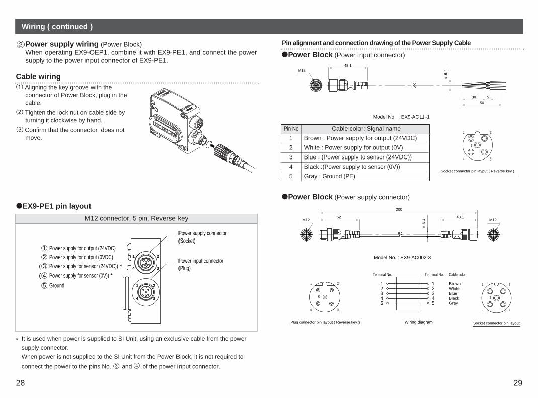
M12 connector, 5 pin, Reverse key
1 Power supply for output (24VDC)
2 Power supply for output (0VDC)
5 Ground
( 3 Power supply for sensor (24VDC)) *
( 4 Power supply for sensor (0V)) *
4
1
4
1 2
3
2
3
5
5
Power supply connector(Socket)
Power input connector(Plug)
* It is used when power is supplied to SI Unit, using an exclusive cable from the power
supply connector.
When power is not supplied to the SI Unit from the Power Block, it is not required to
connect the power to the pins No. and of the power input connector.
Pin alignment and connection drawing of the Power Supply Cable
2
4 3
5
1
Socket connector pin layput ( Reverse key )
Model No. : EX9-AC -1
M12
φ6
.4
30 5
50
48.1
Power Block (Power input connector)
2
4 3
5
1
Socket connector pin layout
Model No. : EX9-AC002-3
φ6
.4
48.152
200
M12 M12
Power Block (Power supply connector)
2
4 3
5
1
Plug connector pin layput ( Reverse key ) Wiring diagram
Cable color
BrownWhiteBlueBlackGray
12345
12345
Terminal No. Terminal No.
Cable wiringAligning the key groove with the connector of Power Block, plug in thecable.
Tighten the lock nut on cable side by turning it clockwise by hand.
Confirm that the connector does notmove.
EX9-PE1 pin layout
Pin No
5
4
3
2
1
Cable color: Signal name
Brown : Power supply for output (24VDC)
White : Power supply for output (0V)
Blue : (Power supply to sensor (24VDC))
Black :(Power supply to sensor (0V))
Gray : Ground (PE)
Power supply wiring (Power Block)When operating EX9-OEP1, combine it with EX9-PE1, and connect the powersupply to the power input connector of EX9-PE1.

30 31
Wiring ( continued )
DisplayOutput Block
PWRPWR
Power Block
The Power Supply Cable (for Power Supply Connector of Power Block) is a bypasscable which can be used when the Power Block is positioned next to the SI Unit.
Option
EX500-AP 050 - SHow to order
Cable length (L) Connector specification010 1 [m]050 5 [m]
S Straight
EX9-AC 020 EN- PSRJ How to order
Connector specificationCable length ( L )020 2 [m] PSRJ M12 plug ( straight ) RJ45 connector
Spare Fuse (for Input Block)
EX9-FU 05How to order
Rating ( A )05 0.5A10 1.0A
Output Cable
For details, refer to subsection "Wiring" (page 26) of section "EX9 series OutputBlock/Power Block" in this manual.
EX9-AC 010 -7How to order
Cable length ( L )010 1 [m]030 3 [m]
Power Supply Cable (for power input connector of Power Block)For details, refer to subsection "Wiring" (page 29) of section "EX9 series Output
Block/Power Block" in this manual.
EX9-AC 010 -1How to order
Cable length ( L )010 1 [m]030 3 [m]050 5 [m]
NOTEMount a Waterproof Cap on unused Power Supply Connector. The proper use ofWaterproof Cap can achieve IP67 Enclosure. (Tightening torque : 0.1N m for M12)For Waterproof Cap, refer to "Option" (page 32) in this manual.
Display Description
0,1Lights up Output corresponding to the number is ON.
Off Output corresponding to the number is OFF.
Display Description
PWRLights up External power supply is ON.
Off External power supply is OFF.
Ethernet Communication CableFor details, refer to subsection "Wiring" (page 12) in section "SI Unit" in this manual.
Power Supply CableFor details, refer to subsection "Wiring" (page 13) of section "SI Unit" in this manual.
EX9-AC 002 How to order
Cable length (L)002 0.2 [m]
Power Supply Cable (for power supply connector of Power Block)
For details, refer to subsection "Wiring" (page 29) of section "EX9 series OutputBlock/Power Block" in this manual.
6

32 33
Option ( continued )
Waterproof CapMounted on the unused ports of the Input Block, Output Block and Power Block.The proper use of this Waterproof Cap can achieve IP67 Enclosure. (The Waterproof Capsare delivered together with the Power Block as accessories.)
9
EX500-AWHow to order
Connector specificationES M8 connector ( for socket ) / 10 pcs.TS M12 connector ( for socket ) / 10 pcs.
End Plate (Input Block side)7
EX250-EA 1How to order
Mounting method1 Standard product2 For DIN rail mounting
Accessory Hexagon thin socket head bolt (2 pcs.)
End Plate R (Output Block side)8
EX9-EA 03How to order
Mounting method03 Standard product04 For DIN rail mounting
12.5
66
6018
75
64.4
12.5
66
60
75
64.4
18
EX250-EA1 EX250-EA2
60
75
66
1812
.5
66
1812
.5
75
60
EX9-EA03 EX9-EA04
Solenoid valvedoes not work
Solenoid valve does notwork as programmed
1
2
Check the power for output (24VDC) is supplied.Check that the connectors are properly connected.Check the communication status of EtherNet/IP.
Check the wiring specification for manifold blockassembly and modify the program.
No input signal eventhough connected withsensor(s)
3 Check the power for input and controlling (24VDC) issupplied.Check that the connectors are properly connected.Check indicator LED of each Input Block lights up.Check the communication status of EtherNet/IP.Check the sensor type (PNP/NPN).
Output equipmentconnected to theOutput Block doesnot operate.
4 Check that the output power (24VDC) is supplied.For the high wattage load type, check that the external power (24VDC) is supplied from the Power Block.Check that the Output Block is applicable to PNP.Check that the connectors for connection are properly connected.Check that the connected load does not exceed the rated load.Check the communication status of EtherNet/IP.
ItemNo. Solution/Corrective action
NOTETighten the Waterproof Cap by the specified tightening torque. (0.05N m for M8, 0.1N m for M12)
Overall system
Troubleshooting

34
Troubleshooting ( continued )
MS LED statusNormal status : Green lights upFatal failure : Red lights up
1 The effect of noise is possible. Checkthe installation conditions. If the troublecannot be solved even if the installationconditions are checked, contact oursales branch.
NS LED statusOffline/Power is OFF : Lights offOnline/Communication is not established :Green flashesOnline/Communication is established : Green lights upMinor communication error occurred :Red flashesFatal communication error occurred : Red lights up
2 Check the signal line from PLC isconnected.Check the wiring and pin number.Check the data rate and addresssetting.
SOL LED lights off3 Check the power for solenoidvalves/output (24VDC) is supplied.Check the power supply voltage forsolenoid valves/output does not dropunder 20V.
ItemNo. Solution/Corrective action
EtherNet/IP compatible communication
PWR LED lights off4 Check the power for input and control(24VDC) is supplied.