etp hydro-grip high pressure pump m-08
TRANSCRIPT

WOODWORkING
ETP HYDRO-GRIPHigh pressure pump M-08
OPERATING MANUAL
Monteringsinstruktion pump M08:Layout 1 2021-01-25 17:03 Sida 1

Position Description Part no.
1 Hydraulic connector 49828
2 High pressure hose 49831
Gauge set 59864
3 Gauge, 0-600 bar, glycerin
4 Washer
Rotary coupling set 59863
4 Washer
5 Rotary coupling
6 Seal ring
7 Compression spring
8 Valve bolt
9 Ball 4.8 mm
10 Valve seat
11 O-Ring
Valve set 59865
12 Seal ring
13 Washer
14 Check valve
15 Air release valve
16 Seal ring
17 Pressure release screw
18 Ball 4.0 mm
19 Valve seat
20 O-Ring
Description Part no.
Grease pump M-08, manual 59800
Including 2 of Grease cartridges. 49811
Grease cartridges can be ordered separately.
We strongly recommend Blasolube 301.
Please see section Technical Specification - Pressurizing medium.
Accessories
Spare parts list
2
Monteringsinstruktion pump M08:Layout 1 2021-01-25 17:03 Sida 2

Exploded view drawing
3
Monteringsinstruktion pump M08:Layout 1 2021-01-25 17:03 Sida 3

Accessories 2
Spare Parts List 2
Exploded view drawing 3
Table of Content 4
Safety Warning 5
Proper Use 5
Operator’s Obligations 5
Basic Safety Instructions 5
Safety- and Danger Symbols 6
Safety Instructions for the Use of the Product 6
Maintenance, Service and Troubleshooting 6
Warranty and Liability 7
Designations of the components shown (Figure A–B) 8
Assembly/ Installation 9
Directions for use 9
Operation - Filling with cartridge 9
Operating instructions 10
Packing, Transport and Storage 11
Transport Damages 11
Storage 11
Fault Localisation, Troubleshooting 12-13
Designations of the components shown (Figure C–D) 12
Training of Personnel 14
Customer Service/Support 14
De-Commissioning 14
Drawings and Replacement Parts 14
Idling and Disposal 14
Re-Sale 15
Table of Content
4
Monteringsinstruktion pump M08:Layout 1 2021-01-25 17:03 Sida 4

Safety Warning
Read this Operating manual through carefully in order to familiarise yourself with
the safe and efficient operation of this product. keep this manual for reference
purposes. This Operating manual contains important instructions and directives
for the safe and proper operation of the product. It should also help operating
and maintenance personnel to minimise dangers, repair costs and down times
and increase the reliability and operational life of the product. For that reason it is
important to assure at all times access to this document to everyone who is
assigned with the supervision of this product.
Proper Use
The product may only be used in the operational conditions for which it is
designed. Any use that goes beyond this is deemed improper. The
manufacturer is not liable for any damages resulting from improper use.
Also included in proper use are:
• Observing and following all instructions and warnings in this Operating manual
• Completion of inspection and maintenance work as scheduled.
Operator´s Obligations
The party responsible for the safety of the product must make sure that:
• only qualified personnel are assigned to work with the product,
• these persons have the Operating manual ready to hand during all of their
work and are required to follow it consistently,
• the rules and regulations for the prevention of accidents that apply at the
site of use are followed and that the scheduled service and maintenance is
completed on time.
Basic Safety Instructions
For the safe handling and smooth operation of this product, you must heed the
following:
• The product may not be used for purposes for which it was not designed.
• No modifications may be made to the product.
• Safe operational condition must be assured at all times. On request, we will
hold a training session for the device in order to provide your personnel
with the knowledge they need.
• All lines, hoses and screw connections need to be checked for tightness
regularly and for externally visible damage. Any damage must be
immediately repaired by technicians and if needed replaced with original parts.
5
Monteringsinstruktion pump M08:Layout 1 2021-01-25 17:03 Sida 5


Designations of the components shown (Figure A-B)
A
B
1. Hydraulic connector
2. High-pressure hose
3. Air release valve
4. Cylinder
5. Actuating lever
6. Locking notch
7. Piston rod
8. Handle
9. Front cover cap
10. Cartridge
11. Rear cover cap
8
Monteringsinstruktion pump M08:Layout 1 2021-01-25 17:03 Sida 8


Operating instructions
Connecting
1. Place hydraulic-connector at end of hose on the high pressure valve.
Ensure that the valve is free of impurities!
2. Close the air release screw.
Applying pressure
3. Actuate lever until gauge indicates pre-selected pressure.
Disconnecting
4. It is imperative that the following procedure is adhered to, otherwise the valve
may come off or the nozzle may be damaged.
5. Turn pressure release screw half a turn to the left. Never unscrew it completely.
Grease will flow back into reservoir. Wait until pressure has decreased.
6. Remove hydraulic-connector with a slight turn from the high-pressure valve.
7. Close pressure release screw.
10
Monteringsinstruktion pump M08:Layout 1 2021-01-25 17:03 Sida 10

Packing, Transport and Storage
The product will be prepared for transport to its first destination by ETP.
The packing unit may not be subjected to any excess load. The packaging and its
content must be protected from moisture. The transport temperature must be kept
between – 20° C and + 40°C.
Transport Damages
If transport damages are discovered during the inspection of incoming goods,
this procedure must be followed:
• Inform delivering party (freight carrier, etc.)
• Make record of damages
• Inform supplier
Storage
Storage and temporary storage in aggressive or humid environments or outdoors
can lead to corrosion and other damages. The storage temperature must be kept
from -20 °C to +40°C.
11
Monteringsinstruktion pump M08:Layout 1 2021-01-25 17:03 Sida 11

Designation of the components (Figure C-D)
1. Pressure gauge
2. Pressure release screw
3. Suction valve
4. Air release valve
5. Connection to the high pressure hose or rigid feed tube
6. Filler
7. Pressure Piston
C
D
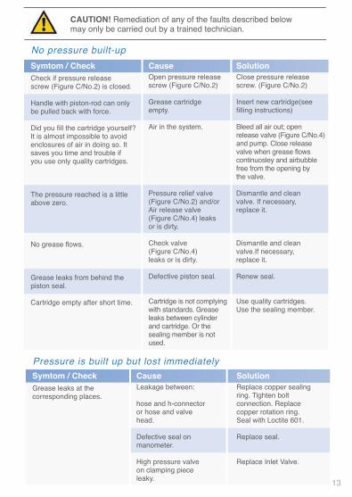
Fault Localisation, Troubleshooting
12
Monteringsinstruktion pump M08:Layout 1 2021-01-25 17:03 Sida 12


Re-Sale
This Operating manual is a component of the product
and belongs in the scope of delivery in the event of re-sale.
Supplier:
ETP Transmission AB
Box 1120
SE-581 11 Linköping
Sweden
Phone: +46 (0)13 24 71 00
www.etp.se
ETP Part nb. 59800
Manufacturer:
Abnox AG
Langackerstrasse 25
CH-6330 CHAM
SWITZERLAND
15
ETP HYDRO-GRIPHigh pressure pump M-08
Monteringsinstruktion pump M08:Layout 1 2021-01-25 17:03 Sida 15

Box 1120, SE-581 11, Linköping, Sweden
Phone: +46 (0)13 24 71 00
E-mail: [email protected], Internet: www.etp.se
E 463-2
Monteringsinstruktion pump M08:Layout 1 2021-01-25 17:03 Sida 16