ets 300 977 - edition 04 - digital cellular - etsi
TRANSCRIPT

DRAFT
EUROPEAN pr ETS 300 977
TELECOMMUNICATION May 1998
STANDARD Fourth Edition
Source: SMG Reference: RE/SMG-091111QR5
ICS: 33.020
Key words : Digital cellular telecommunications system, Global System for Mobile communications (GSM)
GLOBAL SYSTEM FOR MOBILE COM MUNICA TIONS
R
Digital cellular telecommunications s ystem (Phase 2+);Specification of the Subscriber Identity Module -
Mobile Equipment (SIM - ME) interface(GSM 11.11 version 5.9.0)
ETSI
European Telecommunications Standards Institute
ETSI Secretariat
Postal address: F-06921 Sophia Antipolis CEDEX - FRANCEOffice address: 650 Route des Lucioles - Sophia Antipolis - Valbonne - FRANCEInternet: [email protected] - http://www.etsi.fr - http://www.etsi.org
Tel.: +33 4 92 94 42 00 - Fax: +33 4 93 65 47 16
Copyright Notification : No part may be reproduced except as authorized by written permission. The copyright and theforegoing restriction extend to reproduction in all media.
© European Telecommunications Standards Institute 1998. All rights reserved.

Page 2Draft prETS 300 977 (GSM 11.11 version 5.9.0): May 1998
Whilst every care has been taken in the preparation and publication of this document, errors in content,typographical or otherwise, may occur. If you have comments concerning its accuracy, please write to"ETSI Editing and Committee Support Dept." at the address shown on the title page.

Page 3Draft prETS 300 977 (GSM 11.11 version 5.9.0): May 1998
Contents
Foreword .......................................................................................................................................................9
Introduction....................................................................................................................................................9
1 Scope ................................................................................................................................................11
2 Normative references........................................................................................................................11
3 Definitions, abbreviations and symbols .............................................................................................133.1 Definitions ..........................................................................................................................133.2 Abbreviations .....................................................................................................................143.3 Symbols .............................................................................................................................15
4 Physical characteristics .....................................................................................................................164.1 Format and layout ..............................................................................................................16
4.1.1 ID-1 SIM ........................................................................................................164.1.2 Plug-in SIM....................................................................................................16
4.2 Temperature range for card operation...............................................................................164.3 Contacts.............................................................................................................................16
4.3.1 Provision of contacts .....................................................................................164.3.2 Activation and deactivation............................................................................164.3.3 Inactive contacts............................................................................................174.3.4 Contact pressure ...........................................................................................17
4.4 Precedence........................................................................................................................174.5 Static Protection.................................................................................................................17
5 Electronic signals and transmission protocols ..................................................................................175.1 Supply voltage Vcc (contact C1)........................................................................................185.2 Reset (RST) (contact C2) ..................................................................................................185.3 Programming voltage Vpp (contact C6).............................................................................185.4 Clock CLK (contact C3) .....................................................................................................195.5 I/O (contact C7) .................................................................................................................195.6 States.................................................................................................................................195.7 Baudrate ............................................................................................................................205.8 Answer To Reset (ATR).....................................................................................................20
5.8.1 Structure and contents ..................................................................................205.8.2 PTS procedure ..............................................................................................225.8.3 Speed enhancement .....................................................................................23
5.9 Bit/character duration and sampling time ..........................................................................235.10 Error handling ....................................................................................................................23
6 Logical Model ....................................................................................................................................246.1 General description............................................................................................................246.2 File identifier.......................................................................................................................246.3 Dedicated files ...................................................................................................................256.4 Elementary files .................................................................................................................25
6.4.1 Transparent EF .............................................................................................256.4.2 Linear fixed EF ..............................................................................................256.4.3 Cyclic EF .......................................................................................................26
6.5 Methods for selecting a file ................................................................................................276.6 Reservation of file IDs........................................................................................................28
7 Security features ...............................................................................................................................287.1 Authentication and cipher key generation procedure.........................................................287.2 Algorithms and processes .................................................................................................297.3 File access conditions........................................................................................................29

Page 4Draft prETS 300 977 (GSM 11.11 version 5.9.0): May 1998
8 Description of the functions .............................................................................................................. 308.1 SELECT ............................................................................................................................ 308.2 STATUS ............................................................................................................................ 318.3 READ BINARY .................................................................................................................. 318.4 UPDATE BINARY ............................................................................................................. 318.5 READ RECORD................................................................................................................ 318.6 UPDATE RECORD ........................................................................................................... 328.7 SEEK................................................................................................................................. 328.8 INCREASE........................................................................................................................ 338.9 VERIFY CHV..................................................................................................................... 338.10 CHANGE CHV .................................................................................................................. 348.11 DISABLE CHV................................................................................................................... 348.12 ENABLE CHV.................................................................................................................... 348.13 UNBLOCK CHV ................................................................................................................ 358.14 INVALIDATE ..................................................................................................................... 358.15 REHABILITATE................................................................................................................. 358.16 RUN GSM ALGORITHM................................................................................................... 368.17 SLEEP............................................................................................................................... 368.18 TERMINAL PROFILE........................................................................................................ 368.19 ENVELOPE....................................................................................................................... 368.20 FETCH .............................................................................................................................. 368.21 TERMINAL RESPONSE ................................................................................................... 36
9 Description of the commands........................................................................................................... 379.1 Mapping principles ............................................................................................................ 379.2 Coding of the commands .................................................................................................. 39
9.2.1 SELECT........................................................................................................ 409.2.2 STATUS........................................................................................................ 439.2.3 READ BINARY.............................................................................................. 439.2.4 UPDATE BINARY......................................................................................... 449.2.5 READ RECORD ........................................................................................... 449.2.6 UPDATE RECORD....................................................................................... 449.2.7 SEEK ............................................................................................................ 449.2.8 INCREASE ................................................................................................... 459.2.9 VERIFY CHV ................................................................................................ 459.2.10 CHANGE CHV.............................................................................................. 469.2.11 DISABLE CHV .............................................................................................. 469.2.12 ENABLE CHV ............................................................................................... 469.2.13 UNBLOCK CHV............................................................................................ 469.2.14 INVALIDATE................................................................................................. 479.2.15 REHABILITATE ............................................................................................ 479.2.16 RUN GSM ALGORITHM .............................................................................. 479.2.17 SLEEP .......................................................................................................... 479.2.18 GET RESPONSE ......................................................................................... 479.2.19 TERMINAL PROFILE ................................................................................... 489.2.20 ENVELOPE .................................................................................................. 489.2.21 FETCH.......................................................................................................... 489.2.22 TERMINAL RESPONSE............................................................................... 48
9.3 Definitions and coding ....................................................................................................... 489.4 Status conditions returned by the card.............................................................................. 50
9.4.1 Responses to commands which are correctly executed .............................. 509.4.2 Responses to commands which are postponed........................................... 509.4.3 Memory management................................................................................... 509.4.4 Referencing management ............................................................................ 509.4.5 Security management................................................................................... 519.4.6 Application independent errors ..................................................................... 519.4.7 Commands versus possible status responses ............................................. 51
10 Contents of the Elementary Files (EF).............................................................................................. 5210.1 Contents of the EFs at the MF level .................................................................................. 53
10.1.1 EFICCID (ICC Identification)......................................................................... 5310.1.2 EFELP (Extended language preference) ........................................................ 53
10.2 DFs at the GSM application level ...................................................................................... 54

Page 5Draft prETS 300 977 (GSM 11.11 version 5.9.0): May 1998
10.3 Contents of files at the GSM application level ...................................................................5410.3.1 EFLP (Language preference)........................................................................5410.3.2 EFIMSI (IMSI)................................................................................................5510.3.3 EFKc (Ciphering key Kc) ...............................................................................5610.3.4 EFPLMNsel (PLMN selector) ........................................................................5610.3.5 EFHPLMN (HPLMN search period) ..............................................................5710.3.6 EFACMmax (ACM maximum value) .............................................................5810.3.7 EFSST (SIM service table)............................................................................5910.3.8 EFACM (Accumulated call meter).................................................................6110.3.9 EFGID1 (Group Identifier Level 1).................................................................6110.3.10 EFGID2 (Group Identifier Level 2).................................................................6110.3.11 EFSPN (Service Provider Name) ..................................................................6210.3.12 EFPUCT (Price per unit and currency table).................................................6210.3.13 EFCBMI (Cell broadcast message identifier selection).................................6310.3.14 EFBCCH (Broadcast control channels).........................................................6410.3.15 EFACC (Access control class) ......................................................................6410.3.16 EFFPLMN (Forbidden PLMNs) .....................................................................6410.3.17 EFLOCI (Location information) .....................................................................6510.3.18 EFAD (Administrative data)...........................................................................6710.3.19 EFPhase (Phase identification) .....................................................................6810.3.20 EFVGCS (Voice Group Call Service) ............................................................6810.3.21 EFVGCSS (Voice Group Call Service Status) ..............................................6910.3.22 EFVBS (Voice Broadcast Service) ................................................................6910.3.23 EFVBSS (Voice Broadcast Service Status) ..................................................7010.3.24 EFeMLPP (enhanced Multi Level Pre-emption and Priority) .........................7010.3.25 EFAAeM (Automatic Answer for eMLPP Service).........................................7110.3.26 EFCBMID (Cell Broadcast Message Identifier for Data Download) ..............7210.3.27 EFECC (Emergency Call Codes) ..................................................................7310.3.28 EFCBMIR (Cell broadcast message identifier range selection) ....................7310.3.29 EFDCK De-personalization Control Keys......................................................7410.3.30 EFCNL(Co-operative Network List)...............................................................7410.3.31 EFNIA(Network’s Indication of Alerting) ........................................................76
10.4 Contents of files at the telecom level .................................................................................7610.4.1 EFADN (Abbreviated dialling numbers) ........................................................7710.4.2 EFFDN (Fixed dialling numbers) ...................................................................8010.4.3 EFSMS (Short messages) ............................................................................8010.4.4 EFCCP (Capability configuration parameters) ..............................................8210.4.5 EFMSISDN (MSISDN) ..................................................................................8210.4.6 EFSMSP (Short message service parameters) ............................................8210.4.7 EFSMSS (SMS status)..................................................................................8410.4.8 EFLND (Last number dialled)........................................................................8510.4.9 EFSDN (Service Dialling Numbers) ..............................................................8510.4.10 EFEXT1 (Extension1)....................................................................................8610.4.11 EFEXT2 (Extension2)....................................................................................8710.4.12 EFEXT3 (Extension3)....................................................................................8710.4.13 EFBDN (Barred Dialling Numbers)................................................................8810.4.14 EFEXT4 (Extension4)....................................................................................8810.4.15 EFSMSR (Short message status reports).....................................................88
10.5 Files of GSM (figure 8).......................................................................................................89
11 Application protocol ...........................................................................................................................9111.1 General procedures ...........................................................................................................92
11.1.1 Reading an EF ..............................................................................................9211.1.2 Updating an EF .............................................................................................9211.1.3 Increasing an EF ...........................................................................................93
11.2 SIM management procedures ...........................................................................................9311.2.1 SIM initialization.............................................................................................9311.2.2 GSM session termination ..............................................................................9411.2.3 Emergency Call Codes..................................................................................9511.2.4 Language preference ....................................................................................9511.2.5 Administrative information request; ...............................................................9511.2.6 SIM service table request..............................................................................9511.2.7 SIM phase request ........................................................................................95

Page 6Draft prETS 300 977 (GSM 11.11 version 5.9.0): May 1998
11.2.8 SIM Presence Detection and Proactive Polling ............................................ 9511.2.9 Extended Language preference ................................................................... 96
11.3 CHV related procedures.................................................................................................... 9611.3.1.1 CHV verification if ($CHVBLK$) is supported............................................... 9611.3.1.2 CHV verification if ($CHVBLK$) is not supported......................................... 9611.3.2 CHV value substitution ................................................................................. 9711.3.3 CHV disabling ............................................................................................... 9711.3.4 CHV enabling................................................................................................ 9711.3.5 CHV unblocking ............................................................................................ 97
11.4 GSM security related procedures...................................................................................... 9811.4.1 GSM algorithms computation ....................................................................... 9811.4.2 IMSI request ................................................................................................. 9811.4.3 Access control request ................................................................................. 9811.4.4 HPLMN search period request ..................................................................... 9811.4.5 Location information ..................................................................................... 9811.4.6 Cipher key..................................................................................................... 9811.4.7 BCCH information......................................................................................... 9811.4.8 Forbidden PLMN........................................................................................... 98
11.5 Subscription related procedures ....................................................................................... 9811.5.1 Dialling numbers ........................................................................................... 9811.5.2 Short messages.......................................................................................... 10111.5.3 Advice of Charge (AoC).............................................................................. 10111.5.4 Capability configuration parameters ........................................................... 10211.5.5 PLMN selector ............................................................................................ 10211.5.6 Cell broadcast message identifier .............................................................. 10211.5.7 Group identifier level 1................................................................................ 10211.5.8 Group identifier level 2................................................................................ 10211.5.9 Service Provider Name............................................................................... 10211.5.10 Voice Group Call Services.......................................................................... 10211.5.11 Voice Broadcast Services........................................................................... 10311.5.12 Enhanced Multi Level Pre-emption and Priority Service............................. 10311.5.13 Cell Broadcast Message range identifier .................................................... 10311.5.14 Depersonalisation Control Keys.................................................................. 10311.5.15 Short message status report ...................................................................... 10311.5.16 Network’s indication of alerting ................................................................... 104
11.6 SIM Application Toolkit related procedures..................................................................... 10411.6.1 Initialization procedure ................................................................................ 10411.6.2 Proactive polling.......................................................................................... 10411.6.3 Support of commands ................................................................................ 10411.6.4 Support of response codes......................................................................... 10411.6.5 Command-response pairs .......................................................................... 10511.6.6 Independence of normal GSM and SIM Application Toolkit tasks.............. 10511.6.7 Use of BUSY status response .................................................................... 10511.6.8 Use of NULL procedure byte ...................................................................... 10511.6.9 Using the TERMINAL PROFILE, ENVELOPE, and TERMINAL
RESPONSE commands ............................................................................. 10511.6.10 Using the FETCH command....................................................................... 10511.6.11 Data Download via SMS-CB....................................................................... 10611.6.12 Data Download via SMS-PP....................................................................... 10611.6.13 Menu selection............................................................................................ 10611.6.14 Call Control ................................................................................................. 10611.6.15 Proactive SIM ............................................................................................. 10611.6.16 Mobile Originated Short Message control by SIM....................................... 106
Annex A (normative): Plug-in SIM ...................................................................................................... 107
Annex B (normative): Coding of Alpha fields in the SIM for UCS2..................................................... 108
Annex C (informative): FDN/BDN Procedures ..................................................................................... 110
Annex D (informative): Suggested contents of the EFs at pre-personalization .................................... 116
Annex E (Informative): SIM application Toolkit protocol diagrams. ...................................................... 118

Page 7Draft prETS 300 977 (GSM 11.11 version 5.9.0): May 1998
Annex F (informative): Bibliography......................................................................................................125
Annex G (informative): Change history .................................................................................................126
History........................................................................................................................................................127

Page 8Draft prETS 300 977 (GSM 11.11 version 5.9.0): May 1998
Blank page

Page 9Draft prETS 300 977 (GSM 11.11 version 5.9.0): May 1998
Foreword
This draft European Telecommunication Standard (ETS) has been produced by the Special Mobile Group(SMG) of the European Telecommunications Standards Institute (ETSI) and is now submitted for the One-step Approval Procedure phase of the ETSI approval procedure.
This ETS defines the interface between the Subscriber Identity Module (SIM) and the Mobile Equipment(ME) for use during the network operation phase of GSM as well as those aspects of the internalorganization of the SIM which are related to the network operation phase, within the digital cellulartelecommunications system (Phase 2/Phase 2+).
This ETS is a GSM technical specification version 5 and is part of the 1996 release of the GSM TechnicalSpecifications.
The specification from which this ETS has been derived was originally based on CEPT documentation,hence the presentation of this ETS may not be entirely in accordance with the ETSI/PNE Rules.
Proposed transposition dates
Date of latest announcement of this ETS (doa): 3 months after ETSI publication
Date of latest publication of new National Standardor endorsement of this ETS (dop/e): 6 months after doa
Date of withdrawal of any conflicting National Standard (dow): 6 months after doa
Introduction
The present document includes some references to features which are not part of the original Phase 2+release of the GSM Technical specifications. All subclauses which were changed as a result of thesefeatures contain a marker (see table below) relevant to the particular feature. GSM 10.01 will containfurther information about these markers and GSM yearly releases.
The following table lists all new features that were introduced to this document after version 5.5.0.Changes that were made as corrections to existing featurers are not listed in this table. It should be notedthat following a decision made at ETSI SMG #25 requiring that all specifications containing a release 97workitem be released as a version 6.x.y. Consequently, new release 97 features approved at or after ETSISMG #25 are found only in the version 6.x.y of the present document.
Feature Release MarkerExtended Language Preference 1997 $(ELP)$Short Message Status reports 1997 $(SMSR)$Option that a SIM with a disabled CHV can remain unblocked 1997 $(UnBlkSIM)$Network's indication of alerting in the MS 1997 $(NIA)$Dialling Numbers and extensions 1997 $(DNE)$Support of USC2 character set 1997 $(UCS2)$Mobile Originated Short Message Control by SIM 1997 $(MOSMcontrol)$

Page 10Draft prETS 300 977 (GSM 11.11 version 5.9.0): May 1998
Blank page

Page 11Draft prETS 300 977 (GSM 11.11 version 5.9.0): May 1998
1 Scope
This European Telecommunication Standard (ETS) defines the interface between the Subscriber IdentityModule (SIM) and the Mobile Equipment (ME) for use during the network operation phase of GSM as wellas those aspects of the internal organization of the SIM which are related to the network operation phase.This is to ensure interoperability between a SIM and an ME independently of the respective manufacturersand operators. The concept of a split of the Mobile Station (MS) into these elements as well as thedistinction between the GSM network operation phase, which is also called GSM operations, and theadministrative management phase are described in the GSM 02.17 [6].
This ETS defines:
- the requirements for the physical characteristics of the SIM, the electrical signals and thetransmission protocols;
- the model which shall be used as a basis for the design of the logical structure of the SIM;
- the security features;
- the interface functions;
- the commands;
- the contents of the files required for the GSM application;
- the application protocol.
Unless otherwise stated, references to GSM also apply to DCS 1800.
This ETS does not specify any aspects related to the administrative management phase. Any internaltechnical reallocation of either the SIM or the ME are only specified where these reflect over the interface.This ETS does not specify any of the security algorithms which may be used.
This ETS defines the SIM/ME interface for GSM Phase 2. While all attempts have been made to maintainphase compatibility, any issues that specifically relate to Phase 1 should be referenced from within therelevant Phase 1 specification.
2 Normative references
This European Telecommunication Standard (ETS) incorporates, by dated or undated reference,provisions from other publications. These normative references are cited at the appropriate places in thetext and the publications are listed hereafter. For dated references, subsequent amendments to, orrevisions of, any of these publications apply to this ETS only when incorporated in it by amendment orrevision. For undated references the latest edition of the publication referred to applies.
[1] GSM 01.02: "Digital cellular telecommunications system (Phase 2+); Generaldescription of a GSM Public Land Mobile Network (PLMN)".
[2] GSM 01.04 (ETR 350): "Digital cellular telecommunications system (Phase 2+);Abbreviations and acronyms".
[3] GSM 02.07 (ETS 300 906): "Digital cellular telecommunications system(Phase 2+); Mobile Stations (MS) features".
[4] GSM 02.09 (ETS 300 920): "Digital cellular telecommunications system;Security aspects".
[5] GSM 02.11 (ETS 300 921): "Digital cellular telecommunications system;Service accessibility".
[6] GSM 02.17 (ETS 300 922): "Digital cellular telecommunications system;Subscriber Identity Modules (SIM) Functional characteristics".

Page 12Draft prETS 300 977 (GSM 11.11 version 5.9.0): May 1998
[7] GSM 02.24 (ETS 300 923): "Digital cellular telecommunications system;Description of Charge Advice Information (CAI)".
[8] GSM 02.30 (ETS 300 907): "Digital cellular telecommunications system(Phase 2+); Man-Machine Interface (MMI) of the Mobile Station (MS)".
[9] GSM 02.86: "Digital cellular telecommunications system; Advice of charge(AoC) Supplementary Services - Stage 1".
[10] GSM 03.03 (ETS 300 927): "Digital cellular telecommunications system(Phase 2+); Numbering, addressing and identification".
[11] GSM 03.20 (ETS 300 929): "Digital cellular telecommunications system;Security related network functions".
[12] GSM 03.38 (ETS 300 900): "Digital cellular telecommunications system(Phase 2+); Alphabets and language-specific information".
[13] GSM 03.40 (ETS 300 901): "Digital cellular telecommunications system(Phase 2+); Technical realization of the Short Message Service (SMS)Point-to-Point (PP)".
[14] GSM 03.41 (ETS 300 902): "Digital cellular telecommunications system(Phase 2+); Technical realization of Short Message Service Cell Broadcast(SMSCB)".
[15] GSM 04.08 (ETS 300 940): "Digital cellular telecommunications system(Phase 2+); Mobile radio interface layer 3 specification".
[16] GSM 04.11 (ETS 300 942): "Digital cellular telecommunications system(Phase 2+); Point-to-Point (PP) Short Message Service (SMS) support onmobile radio interface".
[17] GSM 09.91 (ETR 174): "Digital cellular telecommunications system;Interworking aspects of the Subscriber Identity Module - Mobile Equipment (SIM- ME) interface between Phase 1 and Phase 2".
[18] CCITT Recommendation E.118: "The international telecommunication chargecard".
[19] CCITT Recommendation E.164: "Numbering plan for the ISDN era".
[20] CCITT Recommendation T.50: "International Alphabet No. 5". (ISO 646: 1983,Information processing - ISO 7-bits coded characters set for informationinterchange).
[21] ISO/IEC 7810 (1995): "Identification cards - Physical characteristics".
[22] ISO/IEC 7811-1 (1995): "Identification cards - Recording technique - Part 1:Embossing".
[23] ISO/IEC 7811-3 (1995): "Identification cards - Recording technique - Part 3:Location of embossed characters on ID-1 cards".
[24] ISO 7816-1 (1987): "Identification cards - Integrated circuit(s) cards withcontacts, Part 1: Physical characteristics".
[25] ISO 7816-2 (1988): "Identification cards - Integrated circuit(s) cards withcontacts, Part 2: Dimensions and locations of the contacts".
[26] ISO/IEC 7816-3 (1989): "Identification cards - Integrated circuit(s) cards withcontacts, Part 3: Electronic signals and transmission protocols".

Page 13Draft prETS 300 977 (GSM 11.11 version 5.9.0): May 1998
[27] GSM 11.14: "Digital cellular telecommunications system (Phase 2+);Specification of the SIM Application Toolkit for the Subscriber Identity Module -Mobile Equipment (SIM - ME) interface".
[28] GSM 11.12 (ETS 300 641): "Digital cellular telecommunications system(Phase 2); Specification of the 3 Volt Subscriber Identity Module - MobileEquipment (SIM - ME) interface".
[29] GSM 02.22: "Digital cellular telecommunications system (Phase 2+);Personalization of GSM Mobile Equipment (ME) Mobile functionalityspecification".
[30] ISO 639 (1988): "Code for the representation of names of languages".
[31] ISO/IEC10646: "Universal Multiple-Octet Coded Character Set (UCS); UCS2, 16bit coding".
3 Definitions, abbreviations and symbols
3.1 Definitions
For the purposes of this ETS, the following definitions apply. For further information and definitions refer toGSM 01.02 [1].
access conditions: A set of security attributes associated with a file.
application: An application consists of a set of security mechanisms, files, data and protocols (excludingtransmission protocols).
application protocol: The set of procedures required by the application.
card session: A link between the card and the external world starting with the ATR and ending with asubsequent reset or a deactivation of the card.
current directory: The latest MF or DF selected.
current EF: The latest EF selected.
data field: Obsolete term for Elementary File.
Dedicated File (DF): A file containing access conditions and, optionally, Elementary Files (EFs) or otherDedicated Files (DFs).
directory: General term for MF and DF.
Elementary File (EF): A file containing access conditions and data and no other files.
file: A directory or an organized set of bytes or records in the SIM.
file identifier: The 2 bytes which address a file in the SIM.
GSM or DCS 1800 application: Set of security mechanisms, files, data and protocols required by GSM orDCS 1800.
GSM session: That part of the card session dedicated to the GSM operation.
IC card SIM: Obsolete term for ID-1 SIM.
ID-1 SIM: The SIM having the format of an ID-1 card (see ISO 7816-1 [24]).
Master File (MF): The unique mandatory file containing access conditions and optionally DFs and/or EFs.

Page 14Draft prETS 300 977 (GSM 11.11 version 5.9.0): May 1998
normal GSM operation: Relating to general, CHV related, GSM security related and subscription relatedprocedures.
padding: One or more bits appended to a message in order to cause the message to contain the requirednumber of bits or bytes.
plug-in SIM: A Second format of SIM (specified in clause 4).
proactive SIM: A SIM which is capable of issuing commands to the ME. Part of SIM Application Toolkit(see clause 11).
record: A string of bytes within an EF handled as a single entity (see clause 6).
record number: The number which identifies a record within an EF.
record pointer: The pointer which addresses one record in an EF.
root directory: Obsolete term for Master File.
SIM application toolkit procedures : Defined in GSM 11.14 [27].
3.2 Abbreviations
For the purpose of this ETS, the following abbreviations apply, in addition to those listed in GSM 01.04 [2]:
A3 Algorithm 3, authentication algorithm; used for authenticating the subscriberA5 Algorithm 5, cipher algorithm; used for enciphering/deciphering dataA8 Algorithm 8, cipher key generator; used to generate KcA38 A single algorithm performing the functions of A3 and A8ACM Accumulated Call MeterADN Abbreviated Dialling NumberADM Access condition to an EF which is under the control of the authority which
creates this fileALW ALWaysAoC Advice of ChargeAPDU Application Protocol Data UnitATR Answer To ResetBCCH Broadcast Control CHannelBCD Binary Coded DecimalBDN Barred Dialling NumberBTS Base Transmitter StationCB Cell BroadcastCBMI Cell Broadcast Message IdentifierCCITT The International Telegraph and Telephone Consultative Committee (now also
known as the ITU Telecommunications Standardization sector)CCP Capability/Configuration ParameterCHV Card Holder Verification information; access condition used by the SIM for the
verification of the identity of the userCLA CLAssCNL Co-operative Network ListDCK De-personalization Control KeysDCS Digital Cellular SystemDF Dedicated File (abbreviation formerly used for Data Field)DTMF Dual Tone Multiple FrequencyECC Emergency Call CodeEF Elementary FileETSI European Telecommunications Standards InstituteeMLPP enhanced Multi-Level Precedence and Pre-emption Serviceetu elementary time unitFDN Fixed Dialling NumberGSM Global System for Mobile communicationsHPLMN Home PLMN

Page 15Draft prETS 300 977 (GSM 11.11 version 5.9.0): May 1998
IC Integrated CircuitICC Integrated Circuit(s) CardID IDentifierIEC International Electrotechnical CommissionIMSI International Mobile Subscriber IdentityISO International Organization for StandardizationKc Cryptographic key; used by the cipher A5Ki Subscriber authentication key; the cryptographic key used by the authentication
algorithm, A3, and cipher key generator, A8LAI Location Area Information; information indicating a cell or a set of cellslgth The (specific) length of a data unitLND Last Number DialledLSB Least Significant BitMCC Mobile Country CodeME Mobile EquipmentMF Master FileMMI Man Machine InterfaceMNC Mobile Network CodeMS Mobile StationMSISDN Mobile Station international ISDN numberMSB Most Significant BitNET NETworkNEV NEVerNPI Numbering Plan IdentifierPIN/PIN2 Personal Identification Number / Personal Identification Number 2 (obsolete
terms for CHV1 and CHV2, respectively)PLMN Public Land Mobile NetworkPTS Protocol Type Select (response to the ATR)PUK/PUK2 PIN Unblocking Key / PIN2 Unblocking Key (obsolete terms for UNBLOCK
CHV1 and UNBLOCK CHV2, respectively)RAND A RANDom challenge issued by the networkRFU Reserved for Future UseSDN Service Dialling NumberSIM Subscriber Identity ModuleSMS Short Message ServiceSRES Signed RESponse calculated by a SIMSSC Supplementary Service Control stringSW1/SW2 Status Word 1 / Status Word 2TMSI Temporary Mobile Subscriber IdentityTON Type Of NumberTP Transfer layer ProtocolTPDU Transfer Protocol Data UnitTS Technical SpecificationUNBLOCK CHV1/2 value to unblock CHV1/CHV2VBS Voice Broadcast ServiceVGCS Voice Group Call ServiceVPLMN Visited PLMN
3.3 Symbols
Vcc Supply voltageVpp Programming voltage'0' to '9' and 'A' to 'F' The sixteen hexadecimal digits$(DNE)$ This marker denotes that text in the relevant subclause contains references to a
specific yearly release. See the introduction for further information.$(ELP)$ see above.$(MOSMcontrol)$ see above.$(NIA)$ see above.$(SMSR)$ see above.$(UCS2)$ see above.$(UnBlkSIM)$ see above.

Page 16Draft prETS 300 977 (GSM 11.11 version 5.9.0): May 1998
4 Physical characteristics
Two physical types of SIM are specified. These are the "ID-1 SIM" and the "Plug-in SIM".
The physical characteristics of both types of SIM shall be in accordance with ISO 7816-1,2 [24, 25] unlessotherwise specified. The following additional requirements shall be applied to ensure proper operation inthe GSM environment.
4.1 Format and layout
The information on the exterior of either SIM should include at least the individual account identifier andthe check digit of the IC Card Identification (see clause 10, EFICCID).
4.1.1 ID-1 SIM
Format and layout of the ID-1 SIM shall be in accordance with ISO 7816-1,2 [24, 25].
The card shall have a polarization mark (see GSM 02.07 [3]) which indicates how the user should insertthe card into the ME.
The ME shall accept embossed ID-1 cards. The embossing shall be in accordance with ISO/IEC 7811 [22,23]. The contacts of the ID-1 SIM shall be located on the front (embossed face, see ISO/IEC 7810 [21]) ofthe card.
NOTE: Card warpage and tolerances are now specified for embossed cards inISO/IEC 7810 [21].
4.1.2 Plug-in SIM
The Plug-in SIM has a width of 25 mm, a height of 15 mm, a thickness the same as an ID-1 SIM and afeature for orientation. See figure A.1 in normative annex A for details of the dimensions of the card andthe dimensions and location of the contacts.
Annexes A.1 and A.2 of ISO 7816-1 [24] do not apply to the Plug-in SIM.
Annex A of ISO 7816-2 [25] applies with the location of the reference points adapted to the smaller size.The three reference points P1, P2 and P3 measure 7,5 mm, 3,3 mm and 20,8 mm, respectively, from 0.The values in table A.1 of ISO 7816-2 [25] are replaced by the corresponding values of figure A.1.
4.2 Temperature range for card operation
The temperature range for full operational use shall be between -25°C and +70°C with occasional peaksof up to +85°C. "Occasional" means not more than 4 hours each time and not over 100 times during thelife time of the card.
4.3 Contacts
4.3.1 Provision of contacts
ME: Contacting elements in the ME in positions C4 and C8 are optional, and are not used in the GSMapplication. They shall present a high impedance to the SIM card in the GSM application. If it isdetermined that the SIM is a multi-application ICC, then these contacts may be used. Contact C6need not be provided for Plug-in SIMs.
SIM: Contacts C4 and C8 need not be provided by the SIM, but if they are provided, then they shall notbe connected internally in the SIM if the SIM only contains the GSM application. Contact C6 shallnot be bonded in the SIM for any function other than supplying Vpp.
4.3.2 Activation and deactivation
The ME shall connect, activate and deactivate the SIM in accordance with the Operating Proceduresspecified in ISO/IEC 7816-3 [26].

Page 17Draft prETS 300 977 (GSM 11.11 version 5.9.0): May 1998
For any voltage level, monitored during the activation sequence, or during the deactivation sequencefollowing soft power-down, the order of the contact activation/deactivation shall be respected.
NOTE 1: Soft Power switching is defined in GSM 02.07 [3].
NOTE 2: It is recommended that whenever possible the deactivation sequence defined inISO/IEC 7816-3 [26] should be followed by the ME on all occasions when the ME ispowered down.
If the SIM clock is already stopped and is not restarted, the ME is allowed to deactivate all the contacts inany order, provided that all signals reach low level before Vcc leaves high level. If the SIM clock is alreadystopped and is restarted before the deactivation sequence, then the deactivation sequence specified inISO/IEC 7816-3 [26] subclause 5.4 shall be followed.
When Vpp is connected to Vcc, as allowed by GSM (see clause 5), then Vpp will be activated anddeactivated with Vcc, at the time of the Vcc activation/deactivation, as given in the sequences ofISO/IEC 7816-3 [26] subclauses 5.1 and 5.4.
The voltage level of Vcc, used by GSM, differs from that specified in ISO/IEC 7816-3 [26]. Vcc is poweredwhen it has a value between 4,5 V and 5,5 V.
4.3.3 Inactive contacts
The voltages on contacts C1, C2, C3, C6 and C7 of the ME shall be between 0 and ± 0,4 volts referencedto ground (C5) when the ME is switched off with the power source connected to the ME. Themeasurement equipment shall have a resistance of 50 kohms when measuring the voltage on C2, C3, C6and C7. The resistance shall be 10 kohms when measuring the voltage on C1.
4.3.4 Contact pressure
The contact pressure shall be large enough to ensure reliable and continuous contact (e.g. to overcomeoxidisation and to prevent interruption caused by vibration). The radius of any curvature of the contactingelements shall be greater than or equal to 0,8 mm over the contact area.
Under no circumstances may a contact force be greater than 0,5 N per contact.
Care shall be taken to avoid undue point pressure to the area of the SIM opposite to the contact area.Otherwise this may damage the components within the SIM.
4.4 Precedence
For Mobile Equipment, which accepts both an ID-1 SIM and a Plug-in SIM, the ID-1 SIM shall takeprecedence over the Plug-in SIM (see GSM 02.17 [6]).
4.5 Static Protection
Considering that the SIM is a CMOS device, the ME manufacturer shall take adequate precautions (inaddition to the protection diodes inherent in the SIM) to safeguard the ME, SIM and SIM/ME interface fromstatic discharges at all times, and particularly during SIM insertion into the ME.
5 Electronic signals and transmission protocols
Electronic signals and transmission protocols shall be in accordance with ISO/IEC 7816-3 [26] unlessspecified otherwise. The following additional requirements shall be applied to ensure proper operation inthe GSM environment.
The choice of the transmission protocol(s), to be used to communicate between the SIM and the ME, shallat least include that specified and denoted by T=0 in ISO/IEC 7816-3 [26].
The values given in the tables hereafter are derived from ISO/IEC 7816-3 [26], subclause 4.2 with thefollowing considerations:

Page 18Draft prETS 300 977 (GSM 11.11 version 5.9.0): May 1998
- VOH and VOL always refer to the device (ME or SIM) which is driving the interface. VIH and VILalways refer to the device (ME or SIM) which is operating as a receiver on the interface.
- This convention is different to the one used in ISO/IEC 7816-3 [26], which specifically defines anICC for which its current conventions apply. The following clauses define the specific corerequirements for the SIM, which provide also the basis for Type Approval. For each state (VOH, VIH,VIL and VOL) a positive current is defined as flowing out of the entity (ME or SIM) in that state.
- The high current options of ISO/IEC 7816-3 [26] for VIH and VOH are not specified for the SIM asthey apply to NMOS technology requirements. No realization of the SIM using NMOS is foreseen.
5.1 Supply voltage Vcc (contact C1)
The SIM shall be operated within the following limits:
Table 1: Electrical characteristics of Vcc under normal operating conditions
Symbol Minimum Maximum UnitVcc 4,5 5,5 VIcc 10 mA
The current consumption of the SIM shall not exceed the value given in table 1 during any state (includingactivation and deactivation as defined in subclause 4.3.2).
When the SIM is in idle state (see below) the current consumption of the card shall not exceed 200 µA at1 MHz and 25°C. If clock stop mode is allowed, then the current consumption shall also not exceed200 µA while the clock is stopped.
The ME shall source the maximum current requirements defined above. It shall also be able to counteractspikes in the current consumption of the card up to a maximum charge of 40 nAs with no more than400 ns duration and an amplitude of at most 200 mA, ensuring that the supply voltage stays in thespecified range.
NOTE: A possible solution would be to place a capacitor (e.g. 100 nF, ceramic) as close aspossible to the contacting elements.
5.2 Reset (RST) (contact C2)
The ME shall operate the SIM within the following limits:
Table 2: Electrical characteristics of RST under normal operating conditions
Symbol Conditions Minimum Maximum
VOH IOHmax = +20 µA Vcc-0,7 Vcc (note)
VOL IOLmax = -200 µA 0V (note) 0,6 V
tR tF Cout = Cin = 30 pF 400 µs
NOTE: To allow for overshoot the voltage on RST shall remainbetween -0,3 V and Vcc+0,3 V during dynamic operation.
5.3 Programming voltage Vpp (contact C6)
SIMs shall not require any programming voltage on Vpp. The ME need not provide contact C6. If the MEprovides contact C6, then, in the case of the ID-1 SIM the same voltage shall be supplied on Vpp as onVcc, while in the case of Plug-in SIMs the ME need not provide any voltage on C6. Contact C6 may beconnected to Vcc in any ME but shall not be connected to ground.

Page 19Draft prETS 300 977 (GSM 11.11 version 5.9.0): May 1998
5.4 Clock CLK (contact C3)
The SIM shall support 1 to 5 MHz. The clock shall be supplied by the ME. No "internal clock" SIMs shallbe used.
If a frequency of 13/4 MHz is needed by the SIM to run the authentication procedure in the allotted time(see GSM 03.20 [11]), or to process an ENVELOPE command used for SIM Data Download, bit 2 of byte1 in the field characteristics shall be set to 1. Otherwise a minimum frequency of 13/8 MHz may be used.
The duty cycle shall be between 40 % and 60 % of the period during stable operation.
The ME shall operate the SIM within the following limits:
Table 3: Electrical characteristics of CLK under normal operating conditions
Symbol Conditions Minimum Maximum
VOH IOHmax = +20 µA 0,7xVcc Vcc (note)
VOL IOLmax = -200 µA 0 V (note) 0,5 V
tR tF Cout = Cin = 30 pF 9 % of period with a maximumof 0,5 µs
NOTE: To allow for overshoot the voltage on CLK shall remain between -0,3 Vand Vcc+0,3 V during dynamic operation.
5.5 I/O (contact C7)
Table 4 defines the electrical characteristics of the I/O (contact C7). The values given in the table have theeffect of defining the values of the pull-up resistor in the ME and the impedances of the drivers andreceivers in the ME and SIM.
Table 4: Electrical characteristics of I/O under normal operating conditions
Symbol Conditions Minimum MaximumVIH IIHmax = ± 20 µA (note 2) 0,7xVcc Vcc+0,3 V
VIL IILmax = +1 mA -0,3 V 0,8 V
VOH (note 1) IOHmax = + 20µA 3,8 V Vcc (note 3)
VOL IOLmax = -1 mA 0 V (note 3) 0,4 V
tR tF Cout = Cin = 30 pF 1 µs
NOTE 1: It is assumed that a pull-up resistor is used in the interface device(recommended value: 20 kohms).
NOTE 2: During static conditions (idle state) only the positive value can apply.Under dynamic operating conditions (transmission) short term voltagespikes on the I/O line may cause a current reversal.
NOTE 3: To allow for overshoot the voltage on I/O shall remain between -0,3 Vand Vcc+0,3 V during dynamic operation.
5.6 States
There are two states for the SIM while the power supply is on:
- The SIM is in operating state when it executes a command. This state also includes transmissionfrom and to the ME.
- The SIM is in idle state at any other time. It shall retain all pertinent data during this state.
Page 20Draft prETS 300 977 (GSM 11.11 version 5.9.0): May 1998
The SIM may support a clock stop mode. The clock shall only be switched off subject to the conditionsspecified in the file characteristics (see clause 9).
Clock stop mode. An ME of Phase 2 or later shall wait at least 1 860 clock cycles after having received thelast character, including the guard time (2 etu), of the response before it switches off the clock (if it isallowed to do so). It shall wait at least 744 clock cycles before it sends the first command after havingstarted the clock.
To achieve phase compatibility, the following procedure shall be adhered to:
A SIM of Phase 2 or later shall always send the status information "normal ending of the command" afterthe successful interpretation of the command SLEEP received from a Phase 1 ME. An ME of Phase 2 orlater shall not send a SLEEP command.
A Phase 1 ME shall wait at least 744 clock cycles after having received the compulsory acknowledgementSW1 SW2 of the SLEEP command before it switches off the clock (if it is allowed to do so). It shall wait atleast 744 clock cycles before it sends the first command after having started the clock.
5.7 Baudrate
The initial baudrate (during ATR) shall be: (clock frequency)/372. Subsequent baudrate shall be: (clockfrequency)/372 unless the PTS procedure has been successfully performed. In that case the negotiatedbaudrate shall be applied according to subclause 5.8.2.
5.8 Answer To Reset (ATR)
The ATR is information presented by the SIM to the ME at the beginning of the card session and givesoperational requirements.
5.8.1 Structure and contents
The following table gives an explanation of the characters specified in ISO/IEC 7816-3 [26] and therequirements for their use in GSM. The answer to reset consists of at most 33 characters. The ME shallbe able to receive interface characters for transmission protocols other than T=0, historical characters anda check byte, even if only T=0 is used by the ME.

Page 21Draft prETS 300 977 (GSM 11.11 version 5.9.0): May 1998
Table 5: ATR
Character Contents sent bythe card
a) evaluation by the MEb) reaction by the ME
1. Initialcharacter
TS
coding convention for allsubsequent characters(direct or inverseconvention)
always a) always
b) using appropriate convention
2. Formatcharacter
T0
subsequent interfacecharacters, number ofhistorical characters
always a) always
b) identifying the subsequentcharacters accordingly
3. Interfacecharacter(global)
TA1
parameters to calculatethe work etu
optional a) always if present
b) if TA1 is not '11', PTS procedureshall be used (see subclause 5.8.2)
4. Interfacecharacter(global)
TB1
parameters to calculatethe programming voltageand current
optional a) always if present
b) if PI1 is not 0, then reject the SIM(in accordance with subclause 5.10)
5. Interfacecharacter(global)
TC1
parameters to calculatethe extra guardtimerequested by the card; noextra guardtime is usedto send characters fromthe card to the ME
optional a) always if present
b) if TC1 is neither 0 nor 255, thenreject the SIM (in accordance withsubclause 5.10); see the note afterthe table
6. Interfacecharacter
TD1
protocol type; indicator forthe presence of inter-face characters,specifying rules to beused for transmissionswith the given protocoltype
optional a) always if present
b) identifying the subsequentcharacters accordingly
7. Interfacecharacter(specific)
TA2
not used for protocol T=0 optional a) optional
b) --------
8. Interfacecharacter(global)
TB2
parameter to calculatethe programming voltage
never the allowed value of TB1 abovedefines that an externalprogramming voltage is notapplicable
9. Interfacecharacter(specific)
TC2
parameters to calculatethe work waiting time
optional a) always if present
b) using the work waiting timeaccordingly
10. Interfacecharacter
TDi(i>1)
protocol type; indicator forthe presence of interfacecharacters, specifyingrules to be used fortransmissions with thegiven protocol type
optional a) always if presentb) identifying the subsequent
characters accordingly
(continued)
Page 22Draft prETS 300 977 (GSM 11.11 version 5.9.0): May 1998
Table 5 (concluded): ATR
Character Contents sent bythe card
a) evaluation by the MEb) reaction by the ME
11. Interfacecharacter
TAi, TBi, TCi(i>2)
characters which containinterface characters forother transmissionprotocols
optional a) optional
b) --------
12. Historicalcharacters
T1,...,TK
contents not specified inISO/IEC
optional a) optional
b) --------
13. Checkcharacter
TCK
check byte (exclusive-ORing)
not sent ifonly T=0 isindicated inthe ATR; inall othercases TCKshall besent
a) optional
b) --------
NOTE: According to ISO/IEC 7816-3:1989/DAM2 (see annex D) N=255 indicates that theminimum delay is 12 etu for the asynchronous half-duplex character transmissionprotocol.
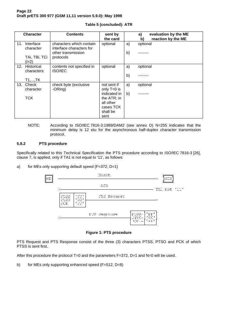
5.8.2 PTS procedure
Specifically related to this Technical Specification the PTS procedure according to ISO/IEC 7816-3 [26],clause 7, is applied, only if TA1 is not equal to '11', as follows:
a) for MEs only supporting default speed (F=372, D=1)
ÅÁÁÈ 5HVHW ÅÁÁÁÈÂ0( ¶¶¶¶¶¶¶¶¶¶¶¶¶¶¶¶¶¶¶¶¶¶¶¶¶¶¶¶¶¶¶¶¶¶¶¶¶¶¶¶¶! Â6,0ÂËÁÁÎ ËÁÁÁÎ
$75�¶¶¶¶¶¶¶¶¶¶¶¶¶¶¶¶¶¶¶¶¶¶¶¶¶¶¶¶¶¶¶¶¶¶¶¶¶¶¶ 7$� QRW ��¸¶¶¶¶¶¾¶¶¶¶¹·3766 ·))· 376 5HTXHVW·376� ·��¼¶¶¶¶¶¶¶¶¶¶¶¶¶¶¶¶¶¶¶¶¶¶¶¶¶¶¶¶¶!·3&. ·))·º¶¶¶¶¶¿¶¶¶¶»
¸¶¶¶¶¶¾¶¶¶¶¹376 5HVSRQVH ·3766 ·))·
�¶¶¶¶¶¶¶¶¶¶¶¶¶¶¶¶¶¶¶¶¶¶¶¶¶¶¶¶¶½376� ·��··3&. ·))·º¶¶¶¶¶¿¶¶¶¶»
Figure 1: PTS procedure
PTS Request and PTS Response consist of the three (3) characters PTSS, PTSO and PCK of whichPTSS is sent first.
After this procedure the protocol T=0 and the parameters F=372, D=1 and N=0 will be used.
b) for MEs only supporting enhanced speed (F=512, D=8)

Page 23Draft prETS 300 977 (GSM 11.11 version 5.9.0): May 1998
ÅÁÁÈ 5HVHW ÅÁÁÁÈÂ0( ¶¶¶¶¶¶¶¶¶¶¶¶¶¶¶¶¶¶¶¶¶¶¶¶¶¶¶¶¶¶¶¶¶¶¶¶¶¶¶¶¶! Â6,0ÂËÁÁÎ ËÁÁÁÎ
$75�¶¶¶¶¶¶¶¶¶¶¶¶¶¶¶¶¶¶¶¶¶¶¶¶¶¶¶¶¶¶¶¶¶¶¶¶¶¶¶ 7$� ��¸¶¶¶¶¶¾¶¶¶¶¹·3766 ·))· 376 5HTXHVW·376� ·��¼¶¶¶¶¶¶¶¶¶¶¶¶¶¶¶¶¶¶¶¶¶¶¶¶¶¶¶¶¶!·376� ·��··3&. ·�%·º¶¶¶¶¶¿¶¶¶¶»
¸¶¶¶¶¶¾¶¶¶¶¹376 5HVSRQVH ·3766 ·))·
�¶¶¶¶¶¶¶¶¶¶¶¶¶¶¶¶¶¶¶¶¶¶¶¶¶¶¶¶¶½376� ·��··376� ·��··3&. ·�%·º¶¶¶¶¶¿¶¶¶¶»
Figure 2: PTS procedure requesting enhanced speed values (F=512, D=8, see clause 5.8.3)
PTS Request and PTS Response consist of the four (4) characters PTSS, PTSO, PTS1 and PCK ofwhich PTSS is sent first.
After this procedure the protocol T=0 and the parameters F=512, D=8 and N=0 will be used.
5.8.3 Speed enhancement
If speed enhancement is implemented the ME and the SIM shall at least support F=512 and D=8 inaddition to F=372 and D=1. However, other values may also be supported. If the ME requests PTS usingvalues other than those above then the PTS procedure shall be initiated accordingly.
The SIM shall support the default value (F=372 and D=1). If the speed enhancement is supported by theSIM it is mandatory that F=512 and D=8 is supported. However, the value in TA1 may even indicate afaster speed (F=512 and D=16). The SIM may also support other values between the default value(F=372 and D=1) and the values indicated in TA1. The SIM shall offer the negotiable mode, to ensurebackwards compatibility with existing MEs. In the negotiable mode the SIM will use default values even ifother parameters are offered in the ATR if the PTS procedure is not initiated.
The ME shall support the default value (F=372 and D=1). If the speed enhancement is supported in theME it is mandatory to support F=512 and D=8. The ME may additionally support other values.
If the SIM does not answer the PTS request within the initial waiting time the ME shall reset the SIM. Aftertwo failed PTS attempts using F=512 and D=8 or values indicated in TA1, (no PTS response from theSIM) the ME shall initiate PTS procedure using default values. If this also fails (no PTS response from theSIM) the ME may proceed using default values without requesting PTS.
If the SIM does not support the values requested by the ME, the SIM shall respond to the PTS requestindicating the use of default values.
5.9 Bit/character duration and sampling time
The bit/character duration and sampling time specified in ISO/IEC 7816-3 [26], subclauses 6.1.1 and6.1.2, are valid for all communications.
5.10 Error handling
Following receipt of an ATR, which is not in accordance with this specification, e.g. because of forbiddenATR characters or too few bytes being transmitted, the ME shall perform a Reset. The ME shall not rejectthe SIM until at least three consecutive wrong ATRs are received.
During the transmission of the ATR and the protocol type selection, the error detection and characterrepetition procedure specified in ISO/IEC 7816-3 [26], subclause 6.1.3, is optional for the ME. For thesubsequent transmission on the basis of T=0 this procedure is mandatory for the ME.
For the SIM the error detection and character repetition procedure is mandatory for all communications.

Page 24Draft prETS 300 977 (GSM 11.11 version 5.9.0): May 1998
6 Logical Model
This clause describes the logical structure for a SIM, the code associated with it, and the structure of filesused.
6.1 General description
Figure 3 shows the general structural relationships which may exist between files. The files are organizedin a hierarchical structure and are of one of three types as defined below. These files may be eitheradministrative or application specific. The operating system handles the access to the data stored indifferent files.
ÅÁÁÁÁÁÁÁÁÁ×ÁÁÁÁÁÁÁÁÁÁÁÁÁÁÁÁÁÁÁÁÁÁÁÁÁÁÁÁÁÁÁÁÁÁÁÁÁÁÁÁÁÁÁÁÁÁÁÈ 0)  Â  ÅÁÁÁÁÁ×ÁÁÁÁÁÁÁÁÁÁÁÁÁÁÁÁÁÁÁÁÁÁÁÁÁÁÁÈ ÂÑÁÁÁÁÁÁÁÁÁÎ Â ')�  ¸¶¶¶¶¹  Â ÑÁÁÁÁÁÎ · () ·  Â ÅÁÁÁÁÁ×ÁÁÁÁÁÚÁÁÁÁÁÁÁÁÁÁÁÁÁÁÁÁÁÁÁÁÁÁÈ º¶¶¶¶»  Â  ')�    Â ÑÁÁÁÁÁÎ ÅÁÁÁÁÁÁ×ÁÁÁÁÁÁÁÁÁÁÁÁÈ Â ¸¶¶¶¶¹  Â   ')��  ÅÁÁÁÁÁÁÁÈ Â Â · () ·  Â  ÑÁÁÁÁÁÁÎ Â ')���    º¶¶¶¶»  Â  ÅÁÁÁÁÁÁ×ÁÚÁÁÁÁÁÁÁÁÈËÁÁÁÁÁÁÁÎ Â Â ����  Â   ')��  ¸¶¶¶¶¹ ÑÁÁÁÁÁÁÁÁÁÁÎ ÑÁÁÁÁÁÁÁÁÁÁΠ  ÑÁÁÁÁÁÁÎ · () ·  ¸¶¶¶¶¹  Â   º¶¶¶¶»  · () ·  ¸¶¶¶¶¹   ËÁÁÁÁÁÁÁÁÁÁÁÁÁÁÁÁÁÎ º¶¶¶¶»  · () ·    º¶¶¶¶»  ËÁÁÁÁÁÁÁÁÁÁÁÁÁÁÁÁÁÁÁÁÁÁÁÁÁÁÁÁÁÁÁÁÁÁΠ ¸¶¶¶¶¹ ¸¶¶¶¶¹  · () · · () ·  º¶¶¶¶» º¶¶¶¶»  ���� ÂËÁÁÁÁÁÁÁÁÁÁÁÁÁÁÁÁÁÁÁÁÁÁÁÁÁÁÁÁÁÁÁÁÁÁÁÁÁÁÁÁÁÁÁÁÁÁÁÁÁÁÁÁÁÁÁÁÁÎ
Figure 3: Organization of memory
Files are composed of a header, which is internally managed by the SIM, and optionally a body part. Theinformation of the header is related to the structure and attributes of the file and may be obtained by usingthe commands GET RESPONSE or STATUS. This information is fixed during the administrative phase.The body part contains the data of the file.
6.2 File identifier
A file ID is used to address or identify each specific file. The file ID consists of two bytes and shall becoded in hexadecimal notation. They are specified in clause 10.
The first byte identifies the type of file, and for GSM is:
- '3F': Master File;- '7F': 1st level Dedicated File;- '5F': 2nd level Dedicated File;- '2F': Elementary File under the Master File;- '6F': Elementary File under a 1st level Dedicated File;- '4F': Elementary File under 2nd level Dedicated File.
File IDs shall be subject to the following conditions:
- the file ID shall be assigned at the time of creation of the file concerned;- no two files under the same parent shall have the same ID;- a child and any parent, either immediate or remote in the hierarchy, e.g. grandparent, shall
never have the same file ID.
In this way each file is uniquely identified.
Page 25Draft prETS 300 977 (GSM 11.11 version 5.9.0): May 1998
6.3 Dedicated files
A Dedicated File (DF) is a functional grouping of files consisting of itself and all those files which containthis DF in their parental hierarchy (that is to say it consists of the DF and its complete "subtree"). A DF"consists" only of a header part.
Two 1st level DFs are defined in this specification:
- DFGSM which contains the applications for both GSM and/or DCS 1800;- DFTELECOM which contains telecom service features.
Both files are immediate children of the Master File (MF) and may coexist on a multi-application card.
2nd level DFs are defined in this specification under DFGSM.
All 2nd level DFs are immediate children of the DFGSM and may coexist on a multi-application card.
6.4 Elementary files
An Elementary File (EF) is composed of a header and a body part. The following three structures of an EFare used by GSM.
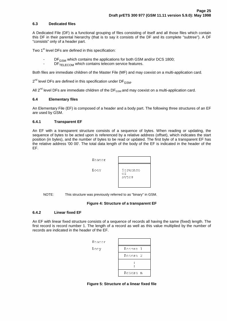
6.4.1 Transparent EF
An EF with a transparent structure consists of a sequence of bytes. When reading or updating, thesequence of bytes to be acted upon is referenced by a relative address (offset), which indicates the startposition (in bytes), and the number of bytes to be read or updated. The first byte of a transparent EF hasthe relative address '00 00'. The total data length of the body of the EF is indicated in the header of theEF.
¸¶¶¶¶¶¶¶¶¶¶¶¶¶¹+HDGHU · ·
ÏÁÁÁÁÁÁÁÁÁÁÁÁÁÒ· ·
%RG\ · 6HTXHQFH ·· RI ·· E\WHV ·· ·· ·º¶¶¶¶¶¶¶¶¶¶¶¶¶»
NOTE: This structure was previously referred to as "binary" in GSM.
Figure 4: Structure of a transparent EF
6.4.2 Linear fixed EF
An EF with linear fixed structure consists of a sequence of records all having the same (fixed) length. Thefirst record is record number 1. The length of a record as well as this value multiplied by the number ofrecords are indicated in the header of the EF.
¸¶¶¶¶¶¶¶¶¶¶¶¶¶¹+HDGHU · ·
ÏÁÁÁÁÁÁÁÁÁÁÁÁÁÒ%RG\ · 5HFRUG � ·
¼¶¶¶¶¶¶¶¶¶¶¶¶¶½· 5HFRUG � ·¼¶¶¶¶¶¶¶¶¶¶¶¶¶½· � ·· � ·¼¶¶¶¶¶¶¶¶¶¶¶¶¶½· 5HFRUG Q ·º¶¶¶¶¶¶¶¶¶¶¶¶¶»
Figure 5: Structure of a linear fixed file

Page 26Draft prETS 300 977 (GSM 11.11 version 5.9.0): May 1998
There are several methods to access records within an EF of this type:
- absolutely using the record number;
- when the record pointer is not set it shall be possible to perform an action on the first or thelast record by using the NEXT or PREVIOUS mode;
- when the record pointer is set it shall be possible to perform an action on this record, the nextrecord (unless the record pointer is set to the last record) or the previous record (unless therecord pointer is set to the first record);
- by identifying a record using pattern seek starting:- forwards from the beginning of the file;
- forwards from the record following the one at which the record pointer is set (unlessthe record pointer is set to the last record);
- backwards from the end of the file;
- backwards from the record preceding the one at which the record pointer is set (unlessthe record pointer is set to the first record).
If an action following selection of a record is aborted, then the record pointer shall remain set at the recordat which it was set prior to the action.
NOTE 1: It is not possible, at present, to have more than 255 records in a file of this type, andeach record cannot be greater than 255 bytes.
NOTE 2: This structure was previously referred to as "formatted" in GSM.
6.4.3 Cyclic EF
Cyclic files are used for storing records in chronological order. When all records have been used forstorage, then the next storage of data shall overwrite the oldest information.
An EF with a cyclic structure consists of a fixed number of records with the same (fixed) length. In this filestructure there is a link between the last record (n) and the first record. When the record pointer is set tothe last record n, then the next record is record 1. Similarly, when the record pointer is set to record 1,then the previous record is record n. The last updated record containing the newest data is recordnumber 1, and the oldest data is held in record number n.
¸¶¶¶¶¶¶¶¶¶¶¶¶¶¹+HDGHU · ·
ÏÁÁÁÁÁÁÁÁÁÁÁÁÁÒ%RG\ · 5HFRUG � · ¶¶¹
¼¶¶¶¶¶¶¶¶¶¶¶¶¶½ ·· 5HFRUG � · ·¼¶¶¶¶¶¶¶¶¶¶¶¶¶½ ·· � · ·· � · ·¼¶¶¶¶¶¶¶¶¶¶¶¶¶½ ·· 5HFRUG Q · ¶¶»º¶¶¶¶¶¶¶¶¶¶¶¶¶»
Figure 6: Structure of a cyclic file
For update operations only PREVIOUS record shall be used. For reading operations, the methods ofaddressing are Next, Previous, Current and Record Number.
After selection of a cyclic file (for either operation), the record pointer shall address the record updated orincreased last. If an action following selection of a record is aborted, then the record pointer shall remainset at the record at which it was set prior to the action.
NOTE: It is not possible, at present, to have more than 255 records in a file of this type, andeach record cannot be greater than 255 bytes.

Page 27Draft prETS 300 977 (GSM 11.11 version 5.9.0): May 1998
6.5 Methods for selecting a file
After the Answer To Reset (ATR), the Master File (MF) is implicitly selected and becomes the CurrentDirectory. Each file may then be selected by using the SELECT function in accordance with the followingrules.
Selecting a DF or the MF sets the Current Directory. After such a selection there is no current EF.Selecting an EF sets the current EF and the Current Directory remains the DF or MF which is the parentof this EF. The current EF is always a child of the Current Directory.
Any application specific command shall only be operable if it is specific to the Current Directory.
The following files may be selected from the last selected file:
- any file which is an immediate child of the Current Directory;- any DF which is an immediate child of the parent of the current DF;- the parent of the Current Directory;- the current DF;- the MF.
This means in particular that a DF shall be selected prior to the selection of any of its EFs. All selectionsare made using the file ID.
The following figure gives the logical structure for the GSM application. GSM defines only two levels ofDFs under the MF.
E F1
D F2
E F3 E F4
M F
E F2
D F1
E F5
D F3
Figure 7: Logical structure
The following table gives the valid selections for GSM for the logical structure in figure 7. Reselection ofthe last selected file is also allowed but not shown.
Table 6: File selection
Last selected file Valid SelectionsMFDF1DF2DF3EF1EF2EF3EF4EF5
DF1, DF2, EF1MF, DF2, DF3, EF2MF, DF1, EF3, EF4MF, DF1, EF5MF, DF1, DF2MF, DF1, DF2, DF3MF, DF1, DF2, EF4MF, DF1, DF2, EF3MF, DF1, DF3

Page 28Draft prETS 300 977 (GSM 11.11 version 5.9.0): May 1998
6.6 Reservation of file IDs
In addition to the identifiers used for the files specified in this TS, the following file IDs are reserved for useby GSM.
Dedicated Files:- administrative use:
'7F 4X', '5F1X', '5F2X'- operational use:
'7F 10' (DFTELECOM), '7F 20' (DFGSM), '7F 21' (DFDCS1800), and '7F 2X', where Xranges from '2' to 'F'.
- reserved under '7F20':'5F30' (DFIRIDIUM), '5F31' (DFGlobalstar), '5F32' (DFICO), '5F33' (DFACeS), ‘5F3X’, where Xranges from '4' to 'F' for other MSS.'5F40'(DFPCS-1900), '5F4Y' where Y ranges from '1' to 'F' and,'5FYX' where Y ranges from '5' to 'F'.
Elementary files:- administrative use:
'6F XX' in the DFs '7F 4X'; '4F XX' in the DFs '5F 1X', '5F2X''6F 1X' in the DFs '7F 10', '7F 20', '7F 21';'4F 1X' in all 2nd level DFs'2F 01', '2F EX' in the MF '3F 00';
- operational use:'6F 2X', '6F 3X', '6F 4X' in '7F 10' and '7F 2X';'4F YX', where Y ranges from '2' to 'F' in all 2nd level DFs.'2F 1X' in the MF '3F 00'.
In all the above, X ranges, unless otherwise stated, from '0' to 'F'.
7 Security features
The security aspects of GSM are described in the normative references GSM 02.09 [4] andGSM 03.20 [11]. This clause gives information related to security features supported by the SIM to enablethe following:
- authentication of the subscriber identity to the network;- data confidentiality over the radio interface;- file access conditions.
7.1 Authentication and cipher key generation procedure
This subclause describes the authentication mechanism and cipher key generation which are invoked bythe network. For the specification of the corresponding procedures across the SIM/ME interface seeclause 11.
The network sends a Random Number (RAND) to the MS. The ME passes the RAND to the SIM in thecommand RUN GSM ALGORITHM. The SIM returns the values SRES and Kc to the ME which arederived using the algorithms and processes given below. The ME sends SRES to the network. Thenetwork compares this value with the value of SRES which it calculates for itself. The comparison of theseSRES values provides the authentication. The value Kc is used by the ME in any future encipheredcommunications with the network until the next invocation of this mechanism.
A subscriber authentication key Ki is used in this procedure. This key Ki has a length of 128 bits and isstored within the SIM for use in the algorithms described below.

Page 29Draft prETS 300 977 (GSM 11.11 version 5.9.0): May 1998
7.2 Algorithms and processes
The names and parameters of the algorithms supported by the SIM are defined in GSM 03.20 [11]. Theseare:
- Algorithm A3 to authenticate the MS to the network;- Algorithm A8 to generate the encryption key.
These algorithms may exist either discretely or combined (into A38) within the SIM. In either case theoutput on the SIM/ME interface is 12 bytes. The inputs to both A3 and A8, or A38, are Ki (128 bits)internally derived in the SIM, and RAND (128 bits) across the SIM/ME interface. The output is SRES(32 bits)/Kc (64 bits) the coding of which is defined in the command RUN GSM ALGORITHM in clause 9.
7.3 File access conditions
Every file has its own specific access condition for each command. The relevant access condition of thelast selected file shall be fulfilled before the requested action can take place.
For each file:
- the access conditions for the commands READ and SEEK are identical;- the access conditions for the commands SELECT and STATUS are ALWays.
No file access conditions are currently assigned by GSM to the MF and the DFs.
The access condition levels are defined in the following table:
Table 7: Access condition level coding
Level Access Condition01234 to 1415
ALWaysCHV1CHV2Reserved for GSM Future UseADMNEVer
The meaning of the file access conditions is as follows:
ALWAYS: The action can be performed without any restriction;
CHV1 (card holder verification 1): The action shall only be possible if one of the following threeconditions is fulfilled:- a correct CHV1 value has already been presented to the SIM during the current session;- the CHV1 enabled/disabled indicator is set to "disabled";
NOTE: Some Phase 1 and Phase 2 SIMs do not necessarily grant access when CHV1is “disabled” and “blocked”.
- UNBLOCK CHV1 has been successfully performed during the current session;
CHV2: The action shall only be possible if one of the following two conditions is fulfilled:
- a correct CHV2 value has already been presented to the SIM during the current session;- UNBLOCK CHV2 has been successfully performed during the current session;
ADM: Allocation of these levels and the respective requirements for their fulfilment are theresponsibility of the appropriate administrative authority
The definition of access condition ADM does not preclude the administrative authority from usingALW, CHV1, CHV2 and NEV if required.
NEVER: The action cannot be performed over the SIM/ME interface. The SIM may perform theaction internally.

Page 30Draft prETS 300 977 (GSM 11.11 version 5.9.0): May 1998
Condition levels are not hierarchical. For instance, correct presentation of CHV2 does not allow actions tobe performed which require presentation of CHV1. A condition level which has been satisfied remainsvalid until the end of the GSM session as long as the corresponding secret code remains unblocked, i.e.after three consecutive wrong attempts, not necessarily in the same card session, the access rightspreviously granted by this secret code are lost immediately. A satisfied CHV condition level applies to bothDFGSM and DFTELECOM.
The ME shall determine whether CHV2 is available by using the response to the STATUS command. IfCHV2 is "not initialized" then CHV2 commands, e.g. VERIFY CHV2, shall not be executable.
8 Description of the functions
This clause gives a functional description of the commands and their respective responses. Associatedstatus conditions, error codes and their corresponding coding are specified in clause 9.
It shall be mandatory for all cards complying with this Standard to support all functions described in thisStandard. The command GET RESPONSE which is needed for the protocol T=0 is specified in clause 9.
The following table lists the file types and structures together with the functions which may act on themduring a GSM session. These are indicated by an asterisk (*).
Table 8: Functions on files in GSM session
FileFunction MF DF EF transparent EF linear fixed EF cyclicSELECT * * * * *STATUS * * * * *READ BINARY *UPDATE BINARY *READ RECORD * *UPDATE RECORD * *SEEK *INCREASE *INVALIDATE * * *REHABILITATE * * *
8.1 SELECT
This function selects a file according to the methods described in clause 6. After a successful selectionthe record pointer in a linear fixed file is undefined. The record pointer in a cyclic file shall address the lastrecord which has been updated or increased.
Input:- file ID.Output:- if the selected file is the MF or a DF:
file ID, total memory space available, CHV enabled/disabled indicator, CHV status and other GSMspecific data;
- if the selected file is an EF:file ID, file size, access conditions, invalidated/not invalidated indicator, structure of EF and length ofthe records in case of linear fixed structure or cyclic structure.

Page 31Draft prETS 300 977 (GSM 11.11 version 5.9.0): May 1998
8.2 STATUS
This function returns information concerning the current directory. A current EF is not affected by theSTATUS function. It is also used to give an opportunity for a pro-active SIM to indicate that the SIM wantsto issue a SIM Application Toolkit command to the ME.
Input:- none.Output:- file ID, total memory space available, CHV enabled/disabled indicator, CHV status and other GSM
specific data (identical to SELECT above).
8.3 READ BINARY
This function reads a string of bytes from the current transparent EF. This function shall only be performedif the READ access condition for this EF is satisfied.
Input:- relative address and the length of the string.Output:- string of bytes.
8.4 UPDATE BINARY
This function updates the current transparent EF with a string of bytes. This function shall only beperformed if the UPDATE access condition for this EF is satisfied. An update can be considered as areplacement of the string already present in the EF by the string given in the update command.
Input:- relative address and the length of the string;- string of bytes.Output:- none.
8.5 READ RECORD
This function reads one complete record in the current linear fixed or cyclic EF. The record to be read isdescribed by the modes below. This function shall only be performed if the READ access condition for thisEF is satisfied. The record pointer shall not be changed by an unsuccessful READ RECORD function.
Four modes are defined:
CURRENT: The current record is read. The record pointer is not affected.
ABSOLUTE: The record given by the record number is read. The record pointer is not affected.
NEXT: The record pointer is incremented before the READ RECORD function is performed and thepointed record is read. If the record pointer has not been previously set within the selected EF, thenREAD RECORD (next) shall read the first record and set the record pointer to this record.
If the record pointer addresses the last record in a linear fixed EF, READ RECORD (next) shall notcause the record pointer to be changed, and no data shall be read.
If the record pointer addresses the last record in a cyclic EF, READ RECORD (next) shall set therecord pointer to the first record in this EF and this record shall be read.
PREVIOUS: The record pointer is decremented before the READ RECORD function is performedand the pointed record is read. If the record pointer has not been previously set within the selectedEF, then READ RECORD (previous) shall read the last record and set the record pointer to thisrecord.
If the record pointer addresses the first record in a linear fixed EF, READ RECORD (previous) shallnot cause the record pointer to be changed, and no data shall be read.

Page 32Draft prETS 300 977 (GSM 11.11 version 5.9.0): May 1998
If the record pointer addresses the first record in a cyclic EF, READ RECORD (previous) shall setthe record pointer to the last record in this EF and this record shall be read.
Input:- mode, record number (absolute mode only) and the length of the record.Output:- the record.
8.6 UPDATE RECORD
This function updates one complete record in the current linear fixed or cyclic EF. This function shall onlybe performed if the UPDATE access condition for this EF is satisfied. The UPDATE can be considered asa replacement of the relevant record data of the EF by the record data given in the command. The recordpointer shall not be changed by an unsuccessful UPDATE RECORD function.
The record to be updated is described by the modes below. Four modes are defined of which onlyPREVIOUS is allowed for cyclic files:
CURRENT: The current record is updated. The record pointer is not affected.
ABSOLUTE: The record given by the record number is updated. The record pointer is not affected.
NEXT: The record pointer is incremented before the UPDATE RECORD function is performed andthe pointed record is updated. If the record pointer has not been previously set within the selectedEF, then UPDATE RECORD (next) shall set the record pointer to the first record in this EF and thisrecord shall be updated. If the record pointer addresses the last record in a linear fixed EF,UPDATE RECORD (next) shall not cause the record pointer to be changed, and no record shall beupdated.
PREVIOUS: For a linear fixed EF the record pointer is decremented before the UPDATE RECORDfunction is performed and the pointed record is updated. If the record pointer has not beenpreviously set within the selected EF, then UPDATE RECORD (previous) shall set the recordpointer to the last record in this EF and this record shall be updated. If the record pointer addressesthe first record in a linear fixed EF, UPDATE RECORD (previous) shall not cause the record pointerto be changed, and no record shall be updated.For a cyclic EF the record containing the oldest data is updated, the record pointer is set to thisrecord and this record becomes record number 1.
Input:- mode, record number (absolute mode only) and the length of the record;- the data used for updating the record.Output:- none.
8.7 SEEK
This function searches through the current linear fixed EF to find a record starting with the given pattern.This function shall only be performed if the READ access condition for this EF is satisfied. Two types ofSEEK are defined:
Type 1 The record pointer is set to the record containing the pattern, no output is available.
Type 2 The record pointer is set to the record containing the pattern, the output is the recordnumber.
NOTE: A Phase 1 SIM only executes type 1 of the SEEK function.
The SIM shall be able to accept any pattern length from 1 to 16 bytes inclusive. The length of the patternshall not exceed the record length.

Page 33Draft prETS 300 977 (GSM 11.11 version 5.9.0): May 1998
Four modes are defined:
- from the beginning forwards;- from the end backwards;- from the next location forwards;- from the previous location backwards.
If the record pointer has not been previously set (its status is undefined) within the selected linear fixedEF, then the search begins:
- with the first record in the case of SEEK from the next location forwards; or- with the last record in the case of SEEK from the previous location backwards.
After a successful SEEK, the record pointer is set to the record in which the pattern was found. The recordpointer shall not be changed by an unsuccessful SEEK function.
Input:- type and mode;- pattern;- length of the pattern.Output:- type 1: none;- type 2: status/record number
8.8 INCREASE
This function adds the value given by the ME to the value of the last increased/updated record of thecurrent cyclic EF, and stores the result into the oldest record. The record pointer is set to this record andthis record becomes record number 1. This function shall be used only if this EF has an INCREASEaccess condition assigned and this condition is fulfilled (see bytes 8 and 10 in the responseparameters/data of the current EF, clause 9). The SIM shall not perform the increase if the result wouldexceed the maximum value of the record (represented by all bytes set to 'FF').
Input:- the value to be added.Output:- value of the increased record;- value which has been added.
8.9 VERIFY CHV
This function verifies the CHV presented by the ME by comparing it with the relevant one stored in theSIM. The verification process is subject to the following conditions being fulfilled:
- CHV is not disabled;- CHV is not blocked.
If the access condition for a function to be performed on the last selected file is CHV1 or CHV2, then asuccessful verification of the relevant CHV is required prior to the use of the function on this file unless theCHV is disabled.
If the CHV presented is correct, the number of remaining CHV attempts for that CHV shall be reset to itsinitial value 3.
If the CHV presented is false, the number of remaining CHV attempts for that CHV shall be decremented.After 3 consecutive false CHV presentations, not necessarily in the same card session, the respectiveCHV shall be blocked and the access condition can never be fulfilled until the UNBLOCK CHV functionhas been successfully performed on the respective CHV.
Input:- indication CHV1/CHV2, CHV.Output:- none.
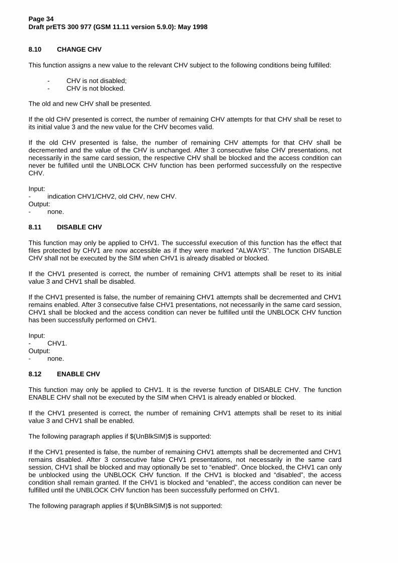
Page 34Draft prETS 300 977 (GSM 11.11 version 5.9.0): May 1998
8.10 CHANGE CHV
This function assigns a new value to the relevant CHV subject to the following conditions being fulfilled:
- CHV is not disabled;- CHV is not blocked.
The old and new CHV shall be presented.
If the old CHV presented is correct, the number of remaining CHV attempts for that CHV shall be reset toits initial value 3 and the new value for the CHV becomes valid.
If the old CHV presented is false, the number of remaining CHV attempts for that CHV shall bedecremented and the value of the CHV is unchanged. After 3 consecutive false CHV presentations, notnecessarily in the same card session, the respective CHV shall be blocked and the access condition cannever be fulfilled until the UNBLOCK CHV function has been performed successfully on the respectiveCHV.
Input:- indication CHV1/CHV2, old CHV, new CHV.Output:- none.
8.11 DISABLE CHV
This function may only be applied to CHV1. The successful execution of this function has the effect thatfiles protected by CHV1 are now accessible as if they were marked "ALWAYS". The function DISABLECHV shall not be executed by the SIM when CHV1 is already disabled or blocked.
If the CHV1 presented is correct, the number of remaining CHV1 attempts shall be reset to its initialvalue 3 and CHV1 shall be disabled.
If the CHV1 presented is false, the number of remaining CHV1 attempts shall be decremented and CHV1remains enabled. After 3 consecutive false CHV1 presentations, not necessarily in the same card session,CHV1 shall be blocked and the access condition can never be fulfilled until the UNBLOCK CHV functionhas been successfully performed on CHV1.
Input:- CHV1.Output:- none.
8.12 ENABLE CHV
This function may only be applied to CHV1. It is the reverse function of DISABLE CHV. The functionENABLE CHV shall not be executed by the SIM when CHV1 is already enabled or blocked.
If the CHV1 presented is correct, the number of remaining CHV1 attempts shall be reset to its initialvalue 3 and CHV1 shall be enabled.
The following paragraph applies if $(UnBlkSIM)$ is supported:
If the CHV1 presented is false, the number of remaining CHV1 attempts shall be decremented and CHV1remains disabled. After 3 consecutive false CHV1 presentations, not necessarily in the same cardsession, CHV1 shall be blocked and may optionally be set to “enabled”. Once blocked, the CHV1 can onlybe unblocked using the UNBLOCK CHV function. If the CHV1 is blocked and “disabled”, the accesscondition shall remain granted. If the CHV1 is blocked and “enabled”, the access condition can never befulfilled until the UNBLOCK CHV function has been successfully performed on CHV1.
The following paragraph applies if $(UnBlkSIM)$ is not supported:

Page 35Draft prETS 300 977 (GSM 11.11 version 5.9.0): May 1998
If the CHV1 presented is false, the number of remaining CHV1 attempts shall be decremented and CHV1remains disabled. After 3 consecutive false CHV1 presentations, not necessarily in the same cardsession, CHV1 shall be blocked and the access condition can never be fulfilled until the UNBLOCK CHVfunction has been successfully performed on CHV1.
Input:- CHV1.Output:- none.
8.13 UNBLOCK CHV
This function unblocks a CHV which has been blocked by 3 consecutive wrong CHV presentations. Thisfunction may be performed whether or not the relevant CHV is blocked.
If the UNBLOCK CHV presented is correct, the value of the CHV, presented together with the UNBLOCKCHV, is assigned to that CHV, the number of remaining UNBLOCK CHV attempts for that UNBLOCKCHV is reset to its initial value 10 and the number of remaining CHV attempts for that CHV is reset to itsinitial value 3. After a successful unblocking attempt the CHV is enabled and the relevant access conditionlevel is satisfied.
If the presented UNBLOCK CHV is false, the number of remaining UNBLOCK CHV attempts for thatUNBLOCK CHV shall be decremented. After 10 consecutive false UNBLOCK CHV presentations, notnecessarily in the same card session, the respective UNBLOCK CHV shall be blocked. A false UNBLOCKCHV shall have no effect on the status of the respective CHV itself.
Input:- indication CHV1/CHV2, the UNBLOCK CHV and the new CHV.Output:- none.
8.14 INVALIDATE
This function invalidates the current EF. After an INVALIDATE function the respective flag in the file statusshall be changed accordingly. This function shall only be performed if the INVALIDATE access conditionfor the current EF is satisfied.
An invalidated file shall no longer be available within the application for any function except for theSELECT and the REHABILITATE functions unless the file status of the EF indicates that READ andUPDATE may also be performed.
Input:- none.Output:- none.
8.15 REHABILITATE
This function rehabilitates the invalidated current EF. After a REHABILITATE function the respective flagin the file status shall be changed accordingly. This function shall only be performed if the REHABILITATEaccess condition for the current EF is satisfied.
If BDN is enabled (see clause 11.5.1) then the REHABILITATE function shall not rehabilitate theinvalidated EFIMSI and EFLOCI until the PROFILE DOWNLOAD procedure is performed indicating that theME supports the "Call control by SIM" facility (see GSM 11.14 [27]).
Input:- none.Output:- none.

Page 36Draft prETS 300 977 (GSM 11.11 version 5.9.0): May 1998
8.16 RUN GSM ALGORITHM
This function is used during the procedure for authenticating the SIM to a GSM network and to calculate acipher key. The card runs the specified algorithms A3 and A8 using a 16 byte random number and thesubscriber authentication key Ki, which is stored in the SIM. The function returns the calculated responseSRES and the cipher key Kc.
The function shall not be executable unless DFGSM or any sub-directory under DFGSM has been selectedas the Current Directory and a successful CHV1 verification procedure has been performed (see 11.3.1).
Input:- RAND.Output:- SRES, Kc.
The contents of Kc shall be presented to algorithm A5 by the ME in its full 64 bit format as delivered by theSIM.
8.17 SLEEP
This is an obsolete GSM function which was issued by Phase 1 MEs. The function shall not be used by anME of Phase 2 or later.
8.18 TERMINAL PROFILE
This function is used by the ME to transmit to the SIM its capabilities concerning the SIM ApplicationToolkit functionality.
Input:- terminal profile.Output:- none.
8.19 ENVELOPE
This function is used to transfer data to the SIM Application Toolkit applications in the SIM.
Input:- data string.Output:- The structure of the data is defined in GSM 11.14 [27].
8.20 FETCH
This function is used to transfer an Application Toolkit command from the SIM to the ME.
Input:- none.Output:- data string containing an SIM Application Toolkit command for the ME.
8.21 TERMINAL RESPONSE
This function is used to transfer from the ME to the SIM the response to a previously fetched SIMApplication Toolkit command.
Input:- data string containing the response.Output:- none.

Page 37Draft prETS 300 977 (GSM 11.11 version 5.9.0): May 1998
9 Description of the commands
This clause states the general principles for mapping the functions described in clause 8 onto ApplicationProtocol Data Units which are used by the transmission protocol.
9.1 Mapping principles
An APDU can be a command APDU or a response APDU.
A command APDU has the following general format:¸¶¶¶¶¾¶¶¶¶¾¶¶¶¶¾¶¶¶¶¾¶¶¶¶¾¶¶¶¶¶¶¶¶¶¶¶¶¶¶¶¶¶¶¶¶¶¶¶¶¶¶¶¶¶¶¶¶¹·&/$ ·,16 · 3� · 3� · 3� · 'DWD ·º¶¶¶¶¿¶¶¶¶¿¶¶¶¶¿¶¶¶¶¿¶¶¶¶¿¶¶¶¶¶¶¶¶¶¶¶¶¶¶¶¶¶¶¶¶¶¶¶¶¶¶¶¶¶¶¶¶»
The response APDU has the following general format:¸¶¶¶¶¶¶¶¶¶¶¶¶¶¶¶¶¶¶¶¶¶¶¶¶¶¶¶¶¶¶¶¶¶¶¶¶¶¶¶¶¶¶¶¶¾¶¶¶¶¶¾¶¶¶¶¶¹· 'DWD · 6:� · 6:� ·º¶¶¶¶¶¶¶¶¶¶¶¶¶¶¶¶¶¶¶¶¶¶¶¶¶¶¶¶¶¶¶¶¶¶¶¶¶¶¶¶¶¶¶¶¿¶¶¶¶¶¿¶¶¶¶¶»
An APDU is transported by the T=0 transmission protocol without any change. Other protocols mightembed an APDU into their own transport structure (ISO/IEC 7816-3 [26]).
The bytes have the following meaning:
- CLA is the class of instruction (ISO/IEC 7816-3 [26]), 'A0' is used in the GSM application;- INS is the instruction code (ISO/IEC 7816-3 [26]) as defined in this subclause for each command;- P1, P2, P3 are parameters for the instruction. They are specified in table 9. 'FF' is a valid value for
P1, P2 and P3. P3 gives the length of the data element. P3='00' introduces a 256 byte data transferfrom the SIM in an outgoing data transfer command (response direction). In an ingoing datatransfer command (command direction), P3='00' introduces no transfer of data.
- SW1 and SW2 are the status words indicating the successful or unsuccessful outcome of thecommand.
For some of the functions described in clause 8 it is necessary for T=0 to use a supplementary transportservice command (GET RESPONSE) to obtain the output data. For example, the SELECT function needsthe following two commands:
- the first command (SELECT) has both parameters and data serving as input for the function;- the second command (GET RESPONSE) has a parameter indicating the length of the data to be
returned.
If the length of the response data is not known beforehand, then its correct length may be obtained byapplying the first command and interpreting the status words. SW1 shall be '9F' and SW2 shall give thetotal length of the data. Other status words may be present in case of an error. The various cases are:
Case 1: No input / No output
·&/$·,16·3�·3�·3�· ·6:�·6:�·º¶¶¶¿¶¶¶¿¶¶¿¶¶¿¶¾» º¶¾¶¿¶¾¶»
OJWK � ��� ����
Case 2: No input / Output of known length
·&/$·,16·3�·3�·3�· · '$7$ ZLWK OHQJWK OJWK ·6:�·6:�·º¶¶¶¿¶¶¶¿¶¶¿¶¶¿¶¾» º¶¶¶¶¶¶¶¶¶¶¶¶¶¶¶¶¶¶¶¶¶¶¶¿¶¾¶¿¶¾¶»
OJWK ����
NOTE: lgth='00' causes a data transfer of 256 bytes.
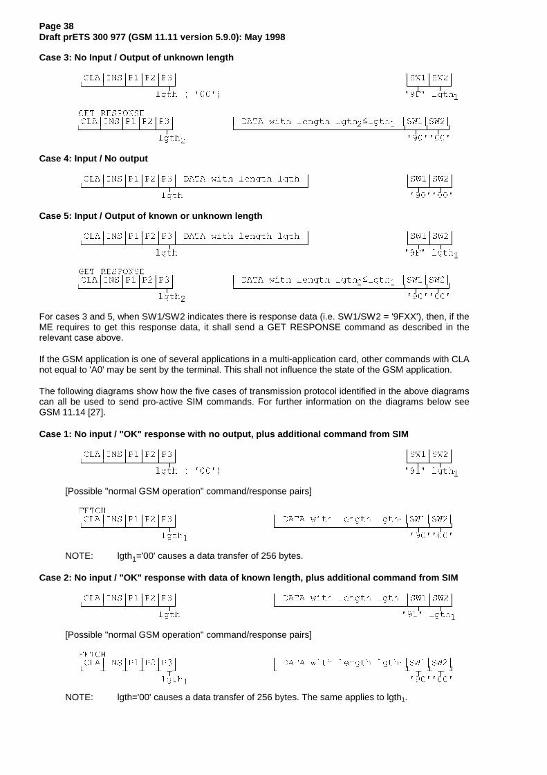
Page 38Draft prETS 300 977 (GSM 11.11 version 5.9.0): May 1998
Case 3: No Input / Output of unknown length
·&/$·,16·3�·3�·3�· ·6:�·6:�·º¶¶¶¿¶¶¶¿¶¶¿¶¶¿¶¾» º¶¾¶¿¶¾¶»
OJWK � ��� �) OJWK�
*(7 5(63216(·&/$·,16·3�·3�·3�· · '$7$ ZLWK OHQJWK OJWK��OJWK� ·6:�·6:�·º¶¶¶¿¶¶¶¿¶¶¿¶¶¿¶¾» º¶¶¶¶¶¶¶¶¶¶¶¶¶¶¶¶¶¶¶¶¶¶¶¶¶¶¶¶¶¶¿¶¾¶¿¶¾¶»
OJWK� ����
Case 4: Input / No output
·&/$·,16·3�·3�·3�· '$7$ ZLWK OHQJWK OJWK · ·6:�·6:�·º¶¶¶¿¶¶¶¿¶¶¿¶¶¿¶¾¿¶¶¶¶¶¶¶¶¶¶¶¶¶¶¶¶¶¶¶¶¶¶¶» º¶¾¶¿¶¾¶»
OJWK ����
Case 5: Input / Output of known or unknown length
·&/$·,16·3�·3�·3�· '$7$ ZLWK OHQJWK OJWK · ·6:�·6:�·º¶¶¶¿¶¶¶¿¶¶¿¶¶¿¶¾¿¶¶¶¶¶¶¶¶¶¶¶¶¶¶¶¶¶¶¶¶¶¶¶» º¶¾¶¿¶¾¶»
OJWK �) OJWK�
*(7 5(63216(·&/$·,16·3�·3�·3�· · '$7$ ZLWK OHQJWK OJWK��OJWK� ·6:�·6:�·º¶¶¶¿¶¶¶¿¶¶¿¶¶¿¶¾» º¶¶¶¶¶¶¶¶¶¶¶¶¶¶¶¶¶¶¶¶¶¶¶¶¶¶¶¶¶¶¿¶¾¶¿¶¾¶»
OJWK� ����
For cases 3 and 5, when SW1/SW2 indicates there is response data (i.e. SW1/SW2 = '9FXX'), then, if theME requires to get this response data, it shall send a GET RESPONSE command as described in therelevant case above.
If the GSM application is one of several applications in a multi-application card, other commands with CLAnot equal to 'A0' may be sent by the terminal. This shall not influence the state of the GSM application.
The following diagrams show how the five cases of transmission protocol identified in the above diagramscan all be used to send pro-active SIM commands. For further information on the diagrams below seeGSM 11.14 [27].
Case 1: No input / "OK" response with no output, plus additional command from SIM
·&/$·,16·3�·3�·3�· ·6:�·6:�·º¶¶¶¿¶¶¶¿¶¶¿¶¶¿¶¾» º¶¾¶¿¶¾¶»
OJWK � ��� �� OJWK�
[Possible "normal GSM operation" command/response pairs]
)(7&+·&/$·,16·3�·3�·3�· · '$7$ ZLWK OHQJWK OJWK�·6:�·6:�·º¶¶¶¿¶¶¶¿¶¶¿¶¶¿¶¾» º¶¶¶¶¶¶¶¶¶¶¶¶¶¶¶¶¶¶¶¶¶¶¶¿¶¾¶¿¶¾¶»
OJWK� ����
NOTE: lgth1='00' causes a data transfer of 256 bytes.
Case 2: No input / "OK" response with data of known length, plus additional command from SIM
·&/$·,16·3�·3�·3�· · '$7$ ZLWK OHQJWK OJWK ·6:�·6:�·º¶¶¶¿¶¶¶¿¶¶¿¶¶¿¶¾» º¶¶¶¶¶¶¶¶¶¶¶¶¶¶¶¶¶¶¶¶¶¶¶¿¶¾¶¿¶¾¶»
OJWK �� OJWK�
[Possible "normal GSM operation" command/response pairs]
)(7&+·&/$·,16·3�·3�·3�· · '$7$ ZLWK OHQJWK OJWK�·6:�·6:�·º¶¶¶¿¶¶¶¿¶¶¿¶¶¿¶¾» º¶¶¶¶¶¶¶¶¶¶¶¶¶¶¶¶¶¶¶¶¶¶¶¿¶¾¶¿¶¾¶»
OJWK� ����
NOTE: lgth='00' causes a data transfer of 256 bytes. The same applies to lgth1.

Page 39Draft prETS 300 977 (GSM 11.11 version 5.9.0): May 1998
Case 3: No Input / "OK" response with data of unknown length, plus additional command fromSIM
·&/$·,16·3�·3�·3�· ·6:�·6:�·º¶¶¶¿¶¶¶¿¶¶¿¶¶¿¶¾» º¶¾¶¿¶¾¶»
OJWK � ��� �) OJWK�
*(7 5(63216(·&/$·,16·3�·3�·3�· · '$7$ ZLWK OHQJWK OJWK��OJWK� ·6:�·6:�·º¶¶¶¿¶¶¶¿¶¶¿¶¶¿¶¾» º¶¶¶¶¶¶¶¶¶¶¶¶¶¶¶¶¶¶¶¶¶¶¶¶¶¶¶¶¶¶¿¶¾¶¿¶¾¶»
OJWK� �� OJWK�
[Possible "normal GSM operation" command/response pairs]
)(7&+·&/$·,16·3�·3�·3�· · '$7$ ZLWK OHQJWK OJWK�·6:�·6:�·º¶¶¶¿¶¶¶¿¶¶¿¶¶¿¶¾» º¶¶¶¶¶¶¶¶¶¶¶¶¶¶¶¶¶¶¶¶¶¶¶¿¶¾¶¿¶¾¶»
OJWK� ����
Case 4: Input / "OK" response with no output data, plus additional command from SIM
·&/$·,16·3�·3�·3�· '$7$ ZLWK OHQJWK OJWK · ·6:�·6:�·º¶¶¶¿¶¶¶¿¶¶¿¶¶¿¶¾¿¶¶¶¶¶¶¶¶¶¶¶¶¶¶¶¶¶¶¶¶¶¶¶» º¶¾¶¿¶¾¶»
OJWK �� OJWK�
[Possible "normal GSM operation" command/response pairs]
)(7&+·&/$·,16·3�·3�·3�· · '$7$ ZLWK OHQJWK OJWK�·6:�·6:�·º¶¶¶¿¶¶¶¿¶¶¿¶¶¿¶¾» º¶¶¶¶¶¶¶¶¶¶¶¶¶¶¶¶¶¶¶¶¶¶¶¿¶¾¶¿¶¾¶»
OJWK� ����
Case 5: Input / "OK" response with data of known or unknown length, plus additional commandfrom SIM
·&/$·,16·3�·3�·3�· '$7$ ZLWK OHQJWK OJWK · ·6:�·6:�·º¶¶¶¿¶¶¶¿¶¶¿¶¶¿¶¾¿¶¶¶¶¶¶¶¶¶¶¶¶¶¶¶¶¶¶¶¶¶¶¶» º¶¾¶¿¶¾¶»
OJWK �) OJWK�
*(7 5(63216(·&/$·,16·3�·3�·3�· · '$7$ ZLWK OHQJWK OJWK��OJWK� ·6:�·6:�·º¶¶¶¿¶¶¶¿¶¶¿¶¶¿¶¾» º¶¶¶¶¶¶¶¶¶¶¶¶¶¶¶¶¶¶¶¶¶¶¶¶¶¶¶¶¶¶¿¶¾¶¿¶¾¶»
OJWK� �� OJWK�
[Possible "normal GSM operation" command/response pairs]
)(7&+·&/$·,16·3�·3�·3�· · '$7$ ZLWK OHQJWK OJWK�·6:�·6:�·º¶¶¶¿¶¶¶¿¶¶¿¶¶¿¶¾» º¶¶¶¶¶¶¶¶¶¶¶¶¶¶¶¶¶¶¶¶¶¶¶¿¶¾¶¿¶¾¶»
OJWK� ����
9.2 Coding of the commands
Table 9 below gives the coding of the commands. The direction of the data is indicated by (S) and (R),where (S) stands for data sent by the ME while (R) stands for data received by the ME. Offset is coded on2 bytes where P1 gives the high order byte and P2 the low order byte. '00 00' means no offset andreading/updating starts with the first byte while an offset of '00 01' means that reading/updating starts withthe second byte.
In addition to the instruction codes specified in table 9 the following codes are reserved:
GSM operational phase:'1X' with X even, from X=6 to X=E.
Administrative management phase:'2A', 'D0', 'D2', 'DE', 'C4', 'C6', 'C8', 'CA', 'CC', 'B4', 'B6', 'B8', 'BA' and 'BC'.
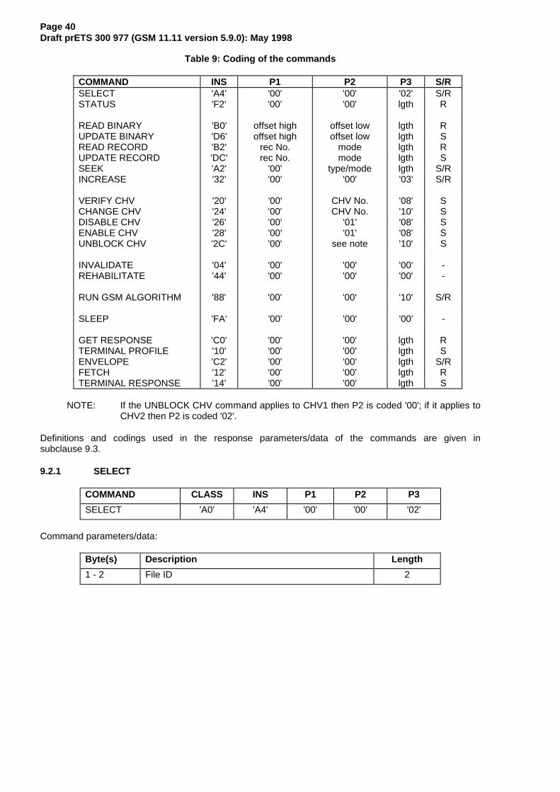
Page 40Draft prETS 300 977 (GSM 11.11 version 5.9.0): May 1998
Table 9: Coding of the commands
COMMAND INS P1 P2 P3 S/RSELECT 'A4' '00' '00' '02' S/RSTATUS 'F2' '00' '00' lgth R
READ BINARY 'B0' offset high offset low lgth RUPDATE BINARY 'D6' offset high offset low lgth SREAD RECORD 'B2' rec No. mode lgth RUPDATE RECORD 'DC' rec No. mode lgth SSEEK 'A2' '00' type/mode lgth S/RINCREASE '32' '00' '00' '03' S/R
VERIFY CHV '20' '00' CHV No. '08' SCHANGE CHV '24' '00' CHV No. '10' SDISABLE CHV '26' '00' '01' '08' SENABLE CHV '28' '00' '01' '08' SUNBLOCK CHV '2C' '00' see note '10' S
INVALIDATE '04' '00' '00' '00' -REHABILITATE '44' '00' '00' '00' -
RUN GSM ALGORITHM '88' '00' '00' '10' S/R
SLEEP 'FA' '00' '00' '00' -
GET RESPONSE 'C0' '00' '00' lgth RTERMINAL PROFILE '10' '00' '00' lgth SENVELOPE 'C2' '00' '00' lgth S/RFETCH '12' '00' '00' lgth RTERMINAL RESPONSE '14' '00' '00' lgth S
NOTE: If the UNBLOCK CHV command applies to CHV1 then P2 is coded '00'; if it applies toCHV2 then P2 is coded '02'.
Definitions and codings used in the response parameters/data of the commands are given insubclause 9.3.
9.2.1 SELECT
COMMAND CLASS INS P1 P2 P3
SELECT 'A0' 'A4' '00' '00' '02'
Command parameters/data:
Byte(s) Description Length
1 - 2 File ID 2

Page 41Draft prETS 300 977 (GSM 11.11 version 5.9.0): May 1998
Response parameters/data in case of an MF or DF:
Byte(s) Description Length
1 - 2 RFU 2
3 - 4 Total amount of memory of the selected directorywhich is not allocated to any of the DFs or EFs underthe selected directory
2
5 - 6 File ID 2
7 Type of file (see subclause 9.3) 1
8 - 12 RFU 5
13 Length of the following data (byte 14 to the end) 1
14 - 34 GSM specific data 21
GSM specific data:
Byte(s) Description Length
14 File characteristics (see detail 1) 1
15 Number of DFs which are a direct child of the currentdirectory
1
16 Number of EFs which are a direct child of the currentdirectory
1
17 Number of CHVs, UNBLOCK CHVs andadministrative codes
1
18 RFU 1
19 CHV1 status (see detail 2) 1
20 UNBLOCK CHV1 status (see detail 2) 1
21 CHV2 status (see detail 2) 1
22 UNBLOCK CHV2 status (see detail 2) 1
23 RFU 1
24 - 34 Reserved for the administrative management 0 � lgth � 11
Bytes 1 - 22 are mandatory and shall be returned by the SIM. Bytes 23 and following are optional and maynot be returned by the SIM.
NOTE 1: Byte 35 and following are RFU.
NOTE 2: The STATUS information of the MF, DFGSM and DFTELECOM provide some identicalapplication specific data, e.g. CHV status. On a multi-application card the MF shouldnot contain any application specific data. Such data is obtained by terminals from thespecific application directories. ME manufacturers should take this into account andtherefore not use application specific data which may exist in the MF of amono-application SIM.
Similarly, the Verify CHV command should not be executed in the MF but in therelevant application directory (e.g. DFGSM).

Page 42Draft prETS 300 977 (GSM 11.11 version 5.9.0): May 1998
Detail 1: File characteristics
¸¶¶¾¶¶¾¶¶¾¶¶¾¶¶¾¶¶¾¶¶¾¶¶¹·E�·E�·E�·E�·E�·E�·E�·E�·º¾¶¿¾¶¿¾¶¿¾¶¿¾¶¿¾¶¿¾¶¿¾¶»· · · · · · · º¶¶ &ORFN VWRS �VHH EHORZ�· · · · · · º¶¶¶¶¶ )RU UXQQLQJ WKH DXWKHQWLFDWLRQ DOJRULWKP�· · · · · · RU WKH (19(/23( FRPPDQG IRU 6,0 'DWD· · · · · · 'RZQORDG� D IUHTXHQF\ LV UHTXLUHG RI DW· · · · · · OHDVW ���� 0+] LI E� � DQG ���� 0+] LI· · · · · · E� �· · · · º¶¶¿¶¶¶¶¶¶¶¶ &ORFN VWRS �VHH EHORZ�· · · º¶¶¶¶¶¶¶¶¶¶¶¶¶¶ IRU FRGLQJ �VHH *60 ����� >��@�· º¶¶¿¶¶¶¶¶¶¶¶¶¶¶¶¶¶¶¶¶ 5)8º¶¶¶¶¶¶¶¶¶¶¶¶¶¶¶¶¶¶¶¶¶¶¶ E� �� &+9� HQDEOHG� E� �� &+9� GLVDEOHG
The coding of the conditions for stopping the clock is as follows:
Bit b1 Bit b3 Bit b4 1 0 0 clock stop allowed, no preferred level 1 1 0 clock stop allowed, high level preferred 1 0 1 clock stop allowed, low level preferred 0 0 0 clock stop not allowed 0 1 0 clock stop not allowed, unless at high level 0 0 1 clock stop not allowed, unless at low level
If bit b1 (column 1) is coded 1, stopping the clock is allowed at high or low level. In this casecolumns 2 (bit b3) and 3 (bit b4) give information about the preferred level (high or low, respectively)at which the clock may be stopped.
If bit b1 is coded 0, the clock may be stopped only if the mandatory condition in column 2 (b3=1, i.e.stop at high level) or column 3 (b4=1, i.e. stop at low level) is fulfilled. If all 3 bits are coded 0, thenthe clock shall not be stopped.
Detail 2: Status byte of a secret code
¸¶¶¾¶¶¾¶¶¾¶¶¾¶¶¾¶¶¾¶¶¾¶¶¹·E�·E�·E�·E�·E�·E�·E�·E�·º¾¶¿¾¶¿¾¶¿¾¶¿¾¶¿¾¶¿¾¶¿¾¶»· · · · º¶¶¿¶¶¿¶¶¿¶¶ 1XPEHU RI IDOVH SUHVHQWDWLRQV UHPDLQLQJ· · · · �� PHDQV EORFNHG�· º¶¶¿¶¶¿¶¶¶¶¶¶¶¶¶¶¶¶¶¶ 5)8º¶¶¶¶¶¶¶¶¶¶¶¶¶¶¶¶¶¶¶¶¶¶¶ E� �� VHFUHW FRGH QRW LQLWLDOLVHG�
E� �� VHFUHW FRGH LQLWLDOLVHG
Response parameters/data in case of an EF:

Page 43Draft prETS 300 977 (GSM 11.11 version 5.9.0): May 1998
Byte(s) Description Length
1 - 2 RFU 2
3 - 4 File size(for transparent EF: the length of the body part of the EF)(for linear fixed or cyclic EF: record length multiplied by thenumber of records of the EF)
2
5 - 6 File ID 2
7 Type of file (see 9.3) 1
8 see detail 3 1
9 - 11 Access conditions (see 9.3) 3
12 File status (see 9.3) 1
13 Length of the following data (byte 14 to the end) 1
14 Structure of EF (see 9.3) 1
15 Length of a record (see detail 4) 1
16 andfollowing
RFU -
Bytes 1-14 are mandatory and shall be returned by the SIM.
Byte 15 is mandatory in case of linear fixed or cyclic EFs and shall be returned by the SIM.
Byte 15 is optional in case of transparent EFs and may not be returned by the SIM.
Byte 16 and following (when defined) are optional and may not be returned by the SIM.
Detail 3: Byte 8
For transparent and linear fixed EFs this byte is RFU. For a cyclic EF all bits except bit 7 are RFU;b7=1 indicates that the INCREASE command is allowed on the selected cyclic file.
Detail 4: Byte 15
For cyclic and linear fixed EFs this byte denotes the length of a record. For a transparent EF, thisbyte shall be coded '00', if this byte is sent by the SIM.
9.2.2 STATUS
COMMAND CLASS INS P1 P2 P3STATUS 'A0' 'F2' '00' '00' lgth
The response parameters/data are identical to the response parameters/data of the SELECT command incase of an MF or DF.
9.2.3 READ BINARY
COMMAND CLASS INS P1 P2 P3READ BINARY 'A0' 'B0' offset high offset low lgth
Response parameters/data:
Byte(s) Description Length
1 - lgth Data to be read lgth

Page 44Draft prETS 300 977 (GSM 11.11 version 5.9.0): May 1998
9.2.4 UPDATE BINARY
COMMAND CLASS INS P1 P2 P3UPDATE BINARY 'A0' 'D6' offset high offset low lgth
Command parameters/data:
Byte(s) Description Length
1 - lgth Data lgth
9.2.5 READ RECORD
COMMAND CLASS INS P1 P2 P3READ RECORD 'A0' 'B2' Rec.No. Mode lgth
Parameter P2 specifies the mode:
- '02' = next record;- '03' = previous record;- '04' = absolute mode/current mode, the record number is given in P1 with P1='00' denoting
the current record.
For the modes "next" and "previous" P1 has no significance and shall be set to '00' by the ME. To ensurephase compatibility between Phase 2 SIMs and Phase 1 MEs, the SIM shall not interpret the value givenby the ME.
Response parameters/data:
Byte(s) Description Length
1 - lgth The data of the record lgth
9.2.6 UPDATE RECORD
COMMAND CLASS INS P1 P2 P3UPDATE RECORD 'A0' 'DC' Rec.No. Mode lgth
Parameter P2 specifies the mode:
- '02' = next record;- '03' = previous record;- '04' = absolute mode/current mode; the record number is given in P1 with P1='00' denoting
the current record.
For the modes "next" and "previous" P1 has no significance and shall be set to '00' by the ME. To ensurephase compatibility between Phase 2 SIMs and Phase 1 MEs, the SIM shall not interpret the value givenby the ME.
Command parameters/data:
Byte(s) Description Length
1 - lgth Data lgth
9.2.7 SEEK
COMMAND CLASS INS P1 P2 P3SEEK 'A0' 'A2' '00' Type/Mode lgth
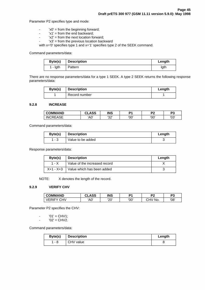
Page 45Draft prETS 300 977 (GSM 11.11 version 5.9.0): May 1998
Parameter P2 specifies type and mode:
- 'x0' = from the beginning forward;- 'x1' = from the end backward;- 'x2' = from the next location forward;- 'x3' = from the previous location backwardwith x='0' specifies type 1 and x='1' specifies type 2 of the SEEK command.
Command parameters/data:
Byte(s) Description Length
1 - lgth Pattern lgth
There are no response parameters/data for a type 1 SEEK. A type 2 SEEK returns the following responseparameters/data:
Byte(s) Description Length
1 Record number 1
9.2.8 INCREASE
COMMAND CLASS INS P1 P2 P3INCREASE 'A0' '32' '00' '00' '03'
Command parameters/data:
Byte(s) Description Length
1 - 3 Value to be added 3
Response parameters/data:
Byte(s) Description Length
1 - X Value of the increased record X
X+1 - X+3 Value which has been added 3
NOTE: X denotes the length of the record.
9.2.9 VERIFY CHV
COMMAND CLASS INS P1 P2 P3VERIFY CHV 'A0' '20' '00' CHV No. '08'
Parameter P2 specifies the CHV:
- '01' = CHV1;- '02' = CHV2.
Command parameters/data:
Byte(s) Description Length
1 - 8 CHV value 8

Page 46Draft prETS 300 977 (GSM 11.11 version 5.9.0): May 1998
9.2.10 CHANGE CHV
COMMAND CLASS INS P1 P2 P3CHANGE CHV 'A0' '24' '00' CHV No. '10'
Parameter P2 specifies the CHV:
- '01' = CHV1;- '02' = CHV2.
Command parameters/data:
Byte(s) Description Length
1 - 8 Old CHV value 8
9 - 16 New CHV value 8
9.2.11 DISABLE CHV
COMMAND CLASS INS P1 P2 P3DISABLE CHV 'A0' '26' '00' '01' '08'
Command parameters/data:
Byte(s) Description Length
1 - 8 CHV1 value 8
9.2.12 ENABLE CHV
COMMAND CLASS INS P1 P2 P3ENABLE CHV 'A0' '28' '00' '01' '08'
Command parameters/data:
Byte(s) Description Length
1 - 8 CHV1 value 8
9.2.13 UNBLOCK CHV
COMMAND CLASS INS P1 P2 P3UNBLOCK CHV 'A0' '2C' '00' CHV No. '10'
Parameter P2 specifies the CHV:
- 00 = CHV1;- 02 = CHV2.
NOTE: The coding '00' for CHV1 differs from the coding of CHV1 used for other commands.
Command parameters/data:
Byte(s) Description Length
1 - 8 UNBLOCK CHV value 8
9 - 16 New CHV value 8

Page 47Draft prETS 300 977 (GSM 11.11 version 5.9.0): May 1998
9.2.14 INVALIDATE
COMMAND CLASS INS P1 P2 P3INVALIDATE 'A0' '04' '00' '00' '00'
9.2.15 REHABILITATE
COMMAND CLASS INS P1 P2 P3REHABILITATE 'A0' '44' '00' '00' '00'
9.2.16 RUN GSM ALGORITHM
COMMAND CLASS INS P1 P2 P3RUN GSMALGORITHM
'A0' '88' '00' '00' '10'
Command parameters/data:
Byte(s) Description Length
1 - 16 RAND 16
Response parameters/data:
Byte(s) Description Length
1 - 4 SRES 4
5 - 12 Cipher Key Kc 8
The most significant bit of SRES is coded on bit 8 of byte 1. The most significant bit of Kc is coded on bit 8of byte 5.
9.2.17 SLEEP
COMMAND CLASS INS P1 P2 P3SLEEP 'A0' 'FA' '00' '00' '00'
NOTE: This command is used by Phase 1 MEs only.
9.2.18 GET RESPONSE
COMMAND CLASS INS P1 P2 P3GET RESPONSE 'A0' 'C0' '00' '00' lgth
The response data depends on the preceding command. Response data is available after the commandsRUN GSM ALGORITHM, SEEK (type 2), SELECT, and INCREASE. If the command GET RESPONSE isexecuted, it is required that it is executed immediately after the command it is related to (no othercommand shall come between the command/response pair and the command GET RESPONSE). If thesequence is not respected, the SIM shall send the status information "technical problem with no diagnosticgiven" as a reaction to the GET RESPONSE.
Since the MF is implicitly selected after activation of the SIM, GET RESPONSE is also allowed as the firstcommand after activation.
The response data itself is defined in the subclause for the corresponding command.

Page 48Draft prETS 300 977 (GSM 11.11 version 5.9.0): May 1998
9.2.19 TERMINAL PROFILE
COMMAND CLASS INS P1 P2 P3TERMINAL PROFILE 'A0' '10' '00' '00' lgth
Command parameters/data:
length OJWK� The structure of the command parameters is defined in GSM 11.14 [27].
Response parameters/data:
none available
9.2.20 ENVELOPE
COMMAND CLASS INS P1 P2 P3ENVELOPE 'A0' 'C2' '00' '00' lgth
Command parameters/data:
length OJWK� The structure of the command parameters is defined in GSM 11.14 [27].
Response parameters/data:
The structure of the data is defined in GSM 11.14 [27].
9.2.21 FETCH
COMMAND CLASS INS P1 P2 P3FETCH 'A0' '12' '00' '00' lgth
Command parameters/data:
QRQH�
Response parameters/data:
length OJWK� The structure of the data is defined in GSM 11.14 [27].
9.2.22 TERMINAL RESPONSE
COMMAND CLASS INS P1 P2 P3TERMINALRESPONSE
'A0' '14' '00' '00' lgth
Command parameters/data:
length OJWK� The structure of the command parameters is defined in GSM 11.14 [27].
Response parameters/data:
none available.
9.3 Definitions and coding
The following definitions and coding are used in the response parameters/data of the commands.
Coding
Each byte is represented by bits b8 to b1, where b8 is the most significant bit (MSB) and b1 is the leastsignificant bit (LSB). In each representation the leftmost bit is the MSB.

Page 49Draft prETS 300 977 (GSM 11.11 version 5.9.0): May 1998
RFU
In a GSM specific card all bytes which are RFU shall be set to '00' and RFU bits to 0. Where the GSMapplication exists on a multiapplication card or is built on a generic telecommunications card (e.g. TE9)then other values may apply. The values will be defined in the appropriate specifications for such cards.These bytes and bits shall not be interpreted by an ME in a GSM session.
File status
¸¶¶¾¶¶¾¶¶¾¶¶¾¶¶¾¶¶¾¶¶¾¶¶¹·E�·E�·E�·E�·E�·E�·E�·E�·º¾¶¿¾¶¿¾¶¿¾¶¿¾¶¿¾¶¿¾¶¿¾¶»· · · · · · · º¶¶ E� �� LQYDOLGDWHG� E� �� QRW LQYDOLGDWHG· · · · · · º¶¶¶¶¶ 5)8· · · · · º¶¶¶¶¶¶¶¶ E� �� QRW UHDGDEOH RU XSGDWDEOH ZKHQ· · · · · LQYDOLGDWHG· · · · · E� �� UHDGDEOH DQG XSGDWDEOH ZKHQ· · · · · LQYDOLGDWHGº¶¶¿¶¶¿¶¶¿¶¶¿¶¶¶¶¶¶¶¶¶¶¶ 5)8
Bit b3 may be set to 1 in special circumstances when it is required that the EF can be read and updatedeven if the EF is invalidated, e.g. reading and updating the EFADN when the FDN feature is enabled, orreading and updating the EFBDN when the BDN feature is disabled.
Structure of file
- '00' transparent;- '01' linear fixed;- '03' cyclic.
Type of File
- '00' RFU;- '01' MF;- '02' DF;- '04' EF.
Coding of CHVs and UNBLOCK CHVs
A CHV is coded on 8 bytes. Only (decimal) digits (0-9) shall be used, coded in CCITT T.50 [20] with bit 8set to zero. The minimum number of digits is 4. If the number of digits presented by the user is less than 8then the ME shall pad the presented CHV with 'FF' before sending it to the SIM.
The coding of the UNBLOCK CHVs is identical to the coding of the CHVs. However, the number of(decimal) digits is always 8.
Coding of Access Conditions
The access conditions for the commands are coded on bytes 9, 10 and 11 of the response data of theSELECT command. Each condition is coded on 4 bits as shown in table 10.
Table 10: Access conditions
¸¶¶¶¶¶¶¶¶¶¶¶¶¶¶¶¶¾¶¶¶¶¶¶¶¹· $/: · � ·· &+9� · � ·· &+9� · � ·· 5)8 · � ·· $'0 · � ·· ������� · �� ·· $'0 · ( ·· 1(9 · ) ·º¶¶¶¶¶¶¶¶¶¶¶¶¶¶¶¶¿¶¶¶¶¶¶¶»
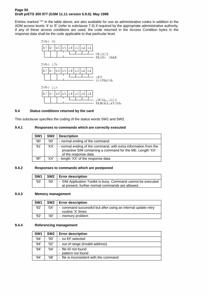
Page 50Draft prETS 300 977 (GSM 11.11 version 5.9.0): May 1998
Entries marked "*" in the table above, are also available for use as administrative codes in addition to theADM access levels '4' to 'E' (refer to subclause 7.3) if required by the appropriate administrative authority.If any of these access conditions are used, the code returned in the Access Condition bytes in theresponse data shall be the code applicable to that particular level.
%\WH ��¸¶¶¾¶¶¾¶¶¾¶¶¾¶¶¾¶¶¾¶¶¾¶¶¹·E�·E�·E�·E�·E�·E�·E�·E�·º¾¶¿¾¶¿¾¶¿¾¶¿¾¶¿¾¶¿¾¶¿¾¶»· · · · º¶¶¿¶¶¿¶¶¿¶¶ 83'$7(º¶¶¿¶¶¿¶¶¿¶¶¶¶¶¶¶¶¶¶¶¶¶¶ 5($'� 6((.
%\WH ���¸¶¶¾¶¶¾¶¶¾¶¶¾¶¶¾¶¶¾¶¶¾¶¶¹·E�·E�·E�·E�·E�·E�·E�·E�·º¾¶¿¾¶¿¾¶¿¾¶¿¾¶¿¾¶¿¾¶¿¾¶»· · · · º¶¶¿¶¶¿¶¶¿¶¶ 5)8º¶¶¿¶¶¿¶¶¿¶¶¶¶¶¶¶¶¶¶¶¶¶¶ ,1&5($6(
%\WH ���¸¶¶¾¶¶¾¶¶¾¶¶¾¶¶¾¶¶¾¶¶¾¶¶¹·E�·E�·E�·E�·E�·E�·E�·E�·º¾¶¿¾¶¿¾¶¿¾¶¿¾¶¿¾¶¿¾¶¿¾¶»· · · · º¶¶¿¶¶¿¶¶¿¶¶ ,19$/,'$7(º¶¶¿¶¶¿¶¶¿¶¶¶¶¶¶¶¶¶¶¶¶¶¶ 5(+$%,/,7$7(
9.4 Status conditions returned by the card
This subclause specifies the coding of the status words SW1 and SW2.
9.4.1 Responses to commands which are correctly executed
SW1 SW2 Description'90' '00' - normal ending of the command
'91' 'XX' - normal ending of the command, with extra information from theproactive SIM containing a command for the ME. Length 'XX'of the response data
'9F' 'XX' - length 'XX' of the response data
9.4.2 Responses to commands which are postponed
SW1 SW2 Error description'93' '00' - SIM Application Toolkit is busy. Command cannot be executed
at present, further normal commands are allowed.
9.4.3 Memory management
SW1 SW2 Error description'92' '0X' - command successful but after using an internal update retry
routine 'X' times'92' '40' - memory problem
9.4.4 Referencing management
SW1 SW2 Error description'94' '00' - no EF selected
'94' '02' - out of range (invalid address)
'94' '04' - file ID not found- pattern not found
'94' '08' - file is inconsistent with the command

Page 51Draft prETS 300 977 (GSM 11.11 version 5.9.0): May 1998
9.4.5 Security management
SW1 SW2 Error description'98' '02' - no CHV initialized
'98' '04' - access condition not fulfilled- unsuccessful CHV verification, at least one attempt left- unsuccessful UNBLOCK CHV verification, at least one attempt
left- authentication failed (see note)
'98' '08' - in contradiction with CHV status
'98' '10' - in contradiction with invalidation status
'98' '40' - unsuccessful CHV verification, no attempt left- unsuccessful UNBLOCK CHV verification, no attempt left- CHV blocked- UNBLOCK CHV blocked
'98' '50' - increase cannot be performed, Max value reached
NOTE: A Phase 1 SIM may send this error code after the third consecutive unsuccessful CHVverification attempt or the tenth consecutive unsuccessful unblocking attempt.
9.4.6 Application independent errors
SW1 SW2 Error description'67' 'XX' - incorrect parameter P3 (see note)
'6B' 'XX'# - incorrect parameter P1 or P2 (see ##)
'6D' 'XX'# - unknown instruction code given in the command
'6E' 'XX'# - wrong instruction class given in the command
'6F' 'XX'# - technical problem with no diagnostic given
# These values of 'XX' are specified by ISO/IEC; at present the default value 'XX'='00' is the only onedefined.
## When the error in P1 or P2 is caused by the addressed record being out of range, then the return code'94 02' shall be used.
NOTE: 'XX' gives the correct length or states that no additional information is given('XX' = '00').
9.4.7 Commands versus possible status responses
The following table shows for each command the possible status conditions returned (marked by anasterisk *).

Page 52Draft prETS 300 977 (GSM 11.11 version 5.9.0): May 1998
Table 11: Commands and status words
OK Busy
Mem
Sta
Refer.Status
SecurityStatus
Applic.Independ.Errors
Commands
90
00
91
XX
9F
XX
93
00
92
0X
92
40
94
00
94
02
94
04
94
08
98
02
98
04
98
08
98
10
98
40
98
50
67
XX
6B
XX
6D
XX
6E
XX
6F
XX
Select * * * * * * *Status * * * * * * *
Update Binary * * * * * * * * * * * *Update Record * * * * * * * * * * * * *Read Binary * * * * * * * * * * *Read Record * * * * * * * * * * * *Seek * * * * * * * * * * * *Increase * * * * * * * * * * * *
Verify CHV * * * * * * * * * * * *Change CHV * * * * * * * * * * * *Disable CHV * * * * * * * * * * * *Enable CHV * * * * * * * * * * * *Unblock CHV * * * * * * * * * * * *
Invalidate * * * * * * * * * * *Rehabilitate * * * * * * * * * * *
Run GSM Algorithm * * * * * * * *
Sleep * * * * *
Get Response * * * * * * *Terminal Profile * * * * * * * *Envelope * * * * * * * * * *Fetch * * * * * *Terminal Response * * * * * * * *
The responses '91 XX' and '93 00' can only be given by a SIM supporting SIM Application Toolkit, to anME also supporting SIM Application Toolkit.
For the SEEK command the response '91 XX' can be given directly after a Type 1 SEEK command.Following the Type 2 SEEK command the SIM can give the response '91 XX' only after the GETRESPONSE command.
10 Contents of the Elementary Files (EF)
This clause specifies the EFs for the GSM session defining access conditions, data items and coding. Adata item is a part of an EF which represents a complete logical entity, e.g. the alpha tag in a EFADNrecord.
EFs or data items having an unassigned value, or, which during the GSM session, are cleared by the ME,shall have their bytes set to 'FF'. After the administrative phase all data items shall have a defined value orhave their bytes set to 'FF'. If a data item is 'deleted' during a GSM session by the allocation of a valuespecified in another GSM TS, then this value shall be used, and the data item is not unassigned; e.g. for adeleted LAI in EFLOCI the last byte takes the value 'FE' (GSM 04.08 [15] refers).
EFs are mandatory (M) or optional (O). The file size of an optional EF may be zero. All implemented EFswith a file size greater than zero shall contain all mandatory data items. Optional data items may either befilled with 'F', or, if located at the end of an EF, need not exist.
When the coding is according to CCITT Recommendation T.50 [20], bit 8 of every byte shall be set to 0.
For an overview containing all files see figure 8.
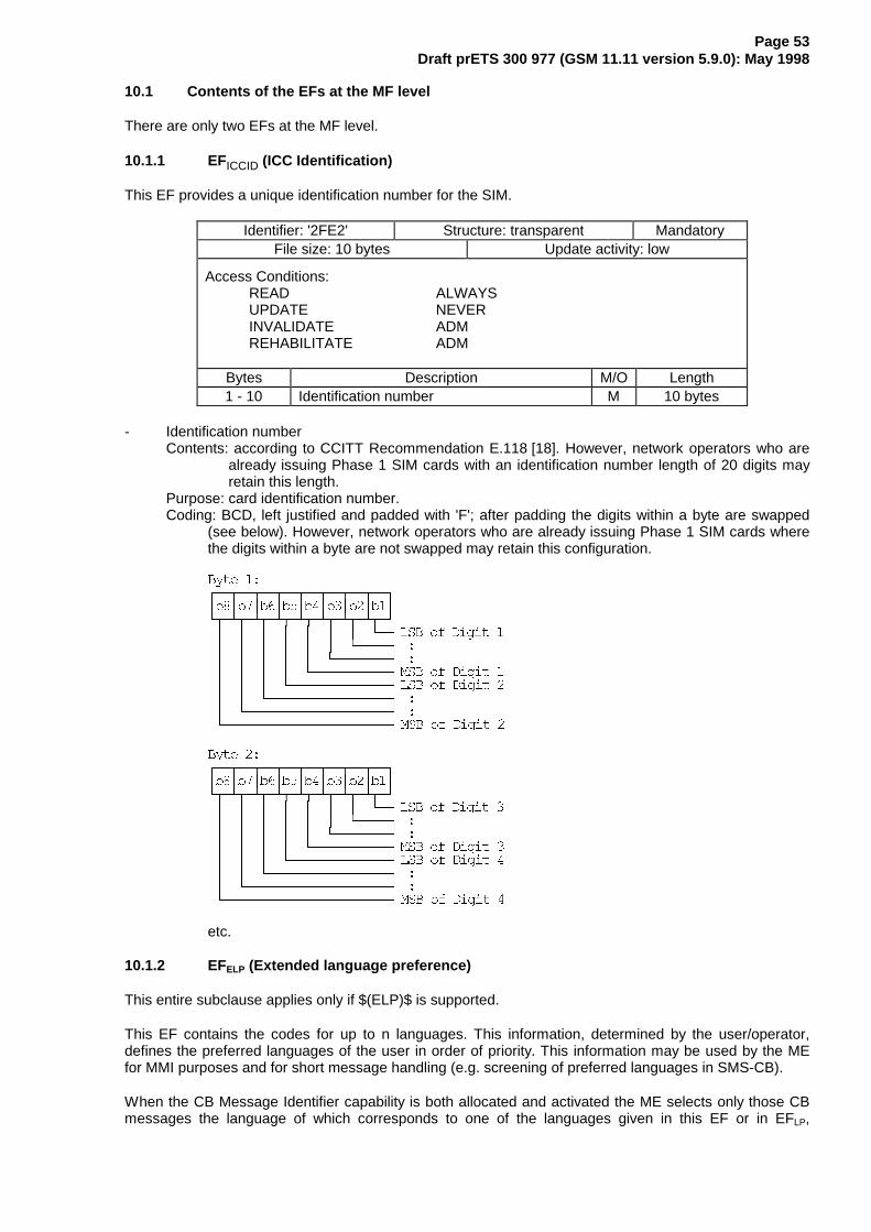
Page 53Draft prETS 300 977 (GSM 11.11 version 5.9.0): May 1998
10.1 Contents of the EFs at the MF level
There are only two EFs at the MF level.
10.1.1 EFICCID (ICC Identification)
This EF provides a unique identification number for the SIM.
Identifier: '2FE2' Structure: transparent MandatoryFile size: 10 bytes Update activity: low
Access Conditions:READ ALWAYSUPDATE NEVERINVALIDATE ADMREHABILITATE ADM
Bytes Description M/O Length1 - 10 Identification number M 10 bytes
- Identification numberContents: according to CCITT Recommendation E.118 [18]. However, network operators who are
already issuing Phase 1 SIM cards with an identification number length of 20 digits mayretain this length.
Purpose: card identification number.Coding: BCD, left justified and padded with 'F'; after padding the digits within a byte are swapped
(see below). However, network operators who are already issuing Phase 1 SIM cards wherethe digits within a byte are not swapped may retain this configuration.
%\WH ��¶̧¶¾¶¶¾¶¶¾¶¶¾¶¶¾¶¶¾¶¶¾¶¶¹·E�·E�·E�·E�·E�·E�·E�·E�·º¾¶¿¾¶¿¾¶¿¾¶¿¾¶¿¾¶¿¾¶¿¾¶»· · · · · · · º¶¶ /6% RI 'LJLW �· · · · · · º¶¶¶¶¶ �· · · · · º¶¶¶¶¶¶¶¶ �· · · · º¶¶¶¶¶¶¶¶¶¶¶ 06% RI 'LJLW �· · · º¶¶¶¶¶¶¶¶¶¶¶¶¶¶ /6% RI 'LJLW �· · º¶¶¶¶¶¶¶¶¶¶¶¶¶¶¶¶¶ �· º¶¶¶¶¶¶¶¶¶¶¶¶¶¶¶¶¶¶¶¶ �º¶¶¶¶¶¶¶¶¶¶¶¶¶¶¶¶¶¶¶¶¶¶¶ 06% RI 'LJLW �
%\WH ��¶̧¶¾¶¶¾¶¶¾¶¶¾¶¶¾¶¶¾¶¶¾¶¶¹·E�·E�·E�·E�·E�·E�·E�·E�·º¾¶¿¾¶¿¾¶¿¾¶¿¾¶¿¾¶¿¾¶¿¾¶»· · · · · · · º¶¶ /6% RI 'LJLW �· · · · · · º¶¶¶¶¶ �· · · · · º¶¶¶¶¶¶¶¶ �· · · · º¶¶¶¶¶¶¶¶¶¶¶ 06% RI 'LJLW �· · · º¶¶¶¶¶¶¶¶¶¶¶¶¶¶ /6% RI 'LJLW �· · º¶¶¶¶¶¶¶¶¶¶¶¶¶¶¶¶¶ �· º¶¶¶¶¶¶¶¶¶¶¶¶¶¶¶¶¶¶¶¶ �º¶¶¶¶¶¶¶¶¶¶¶¶¶¶¶¶¶¶¶¶¶¶¶ 06% RI 'LJLW �
etc.
10.1.2 EFELP (Extended language preference)
This entire subclause applies only if $(ELP)$ is supported.
This EF contains the codes for up to n languages. This information, determined by the user/operator,defines the preferred languages of the user in order of priority. This information may be used by the MEfor MMI purposes and for short message handling (e.g. screening of preferred languages in SMS-CB).
When the CB Message Identifier capability is both allocated and activated the ME selects only those CBmessages the language of which corresponds to one of the languages given in this EF or in EFLP,

Page 54Draft prETS 300 977 (GSM 11.11 version 5.9.0): May 1998
whichever of these EFs is used (see subclause 11.2.1). The CB message language is recognizedaccording to GSM 03.38 by its data coding scheme.
Identifier: '2F 05' Structure: transparent OptionalFile size: 2n bytes Update activity: low
Access Conditions:READ ALWUPDATE CHV1INVALIDATE ADMREHABILITATE ADM
Bytes Description M/O Length1 - 2 1st language code (highest prior.) O 2 bytes3 - 4 2nd language code O 2 bytes
2n-1 - 2n nth language code (lowest prior.) O 2 bytes
Coding: each language code is a pair of alpha-numeric characters, defined in ISO 639 [30]. Eachalpha-numeric character shall be coded on one byte using the SMS default 7-bit codedalphabet as defined in GSM 03.38 [12] with bit 8 set to 0.
Unused language entries shall be set to 'FF FF'.
10.2 DFs at the GSM application level
For compatibility with other systems based on the GSM switching platform, DFs may be present as childdirectories of DFGSM. The following have been defined.
DFIRIDIUM ‘5F30’DFGLOBALSTAR ‘5F31’DFICO ‘5F32’DFACeS ‘5F33’DFPCS1900 ‘5F40’
10.3 Contents of files at the GSM application level
The EFs in the Dedicated File DFGSM contain network related information.
10.3.1 EFLP (Language preference)
This EF contains the codes for one or more languages. This information, determined by the user/operator,defines the preferred languages of the user in order of priority. This information may be used by the MEfor MMI purposes and for short message handling (e.g. screening of preferred languages in SMS-CB).
When the CB Message Identifier capability is both allocated and activated the ME selects only those CBmessages the language of which corresponds to one of the languages given in this EF or if $(ELP)$ issupported, in EFELP, whichever of these EFs is used (see subclause 11.2.1). The CB message languageis recognized according to GSM 03.41 by its data coding scheme.

Page 55Draft prETS 300 977 (GSM 11.11 version 5.9.0): May 1998
Identifier: '6F05' Structure: transparent MandatoryFile size: 1-n bytes Update activity: low
Access Conditions:READ ALWUPDATE CHV1INVALIDATE ADMREHABILITATE ADM
Bytes Description M/O Length1 1st language code (highest prior.) M 1 byte2 2nd language code O 1 byte
n nth language code (lowest prior.) O 1 byte
Coding: according to GSM 03.41 [14].
Using the command GET RESPONSE, the ME can determine the size of the EF.
10.3.2 EFIMSI (IMSI)
This EF contains the International Mobile Subscriber Identity (IMSI).
Identifier: '6F07' Structure: transparent MandatoryFile size: 9 bytes Update activity: low
Access Conditions:READ CHV1UPDATE ADMINVALIDATE ADMREHABILITATE CHV1
Bytes Description M/O Length1 length of IMSI M 1 byte
2 - 9 IMSI M 8 bytes
- length of IMSIContents: The length indicator refers to the number of significant bytes, not including this length
byte, required for the IMSI.Coding: according to GSM 04.08 [15].
- IMSIContents: International Mobile Subscriber Identity.Coding: This information element is of variable length. If a network operator chooses an IMSI of
less than 15 digits, unused nibbles shall be set to 'F'.
%\WH ��¸¶¶¾¶¶¾¶¶¾¶¶¾¶¶¾¶¶¾¶¶¾¶¶¹·E�·E�·E�·E�·E�·E�·E�·E�·º¾¶¿¾¶¿¾¶¿¾¶¿¾¶¿¾¶¿¾¶¿¾¶»· · · · · · · º¶¶ �· · · · · · º¶¶¶¶¶ �· · · · · º¶¶¶¶¶¶¶¶ �· · · · º¶¶¶¶¶¶¶¶¶¶¶ 3DULW\· · · º¶¶¶¶¶¶¶¶¶¶¶¶¶¶ /6% RI 'LJLW �· · º¶¶¶¶¶¶¶¶¶¶¶¶¶¶¶¶¶ �· º¶¶¶¶¶¶¶¶¶¶¶¶¶¶¶¶¶¶¶¶ �º¶¶¶¶¶¶¶¶¶¶¶¶¶¶¶¶¶¶¶¶¶¶¶ 06% RI 'LJLW �
For the parity bit, see GSM 04.08 [15].

Page 56Draft prETS 300 977 (GSM 11.11 version 5.9.0): May 1998
%\WH ��¸¶¶¾¶¶¾¶¶¾¶¶¾¶¶¾¶¶¾¶¶¾¶¶¹·E�·E�·E�·E�·E�·E�·E�·E�·º¾¶¿¾¶¿¾¶¿¾¶¿¾¶¿¾¶¿¾¶¿¾¶»· · · · · · · º¶¶ /6% RI 'LJLW �· · · · · · º¶¶¶¶¶ �· · · · · º¶¶¶¶¶¶¶¶ �· · · · º¶¶¶¶¶¶¶¶¶¶¶ 06% RI 'LJLW �· · · º¶¶¶¶¶¶¶¶¶¶¶¶¶¶ /6% RI 'LJLW �· · º¶¶¶¶¶¶¶¶¶¶¶¶¶¶¶¶¶ �· º¶¶¶¶¶¶¶¶¶¶¶¶¶¶¶¶¶¶¶¶ �º¶¶¶¶¶¶¶¶¶¶¶¶¶¶¶¶¶¶¶¶¶¶¶ 06% RI 'LJLW �
etc.
10.3.3 EFKc (Ciphering key Kc)
This EF contains the ciphering key Kc and the ciphering key sequence number n.
Identifier: '6F20' Structure: transparent MandatoryFile size: 9 bytes Update activity: high
Access Conditions:READ CHV1UPDATE CHV1INVALIDATE ADMREHABILITATE ADM
Bytes Description M/O Length1 - 8 Ciphering key Kc M 8 bytes
9 Ciphering key sequence number n M 1 byte
- Ciphering key KcCoding: The least significant bit of Kc is the least significant bit of the eighth byte. The most
significant bit of Kc is the most significant bit of the first byte.
- Ciphering key sequence number nCoding:
¸¶¶¾¶¶¾¶¶¾¶¶¾¶¶¾¶¶¾¶¶¾¶¶¹·E�·E�·E�·E�·E�·E�·E�·E�·º¾¶¿¾¶¿¾¶¿¾¶¿¾¶¿¾¶¿¾¶¿¾¶»· · · · · º¶¶¿¶¶¿¶¶ Qº¶¶¿¶¶¿¶¶¿¶¶¿¶¶¶¶¶¶¶¶¶¶¶ ELWV E� WR E� DUH FRGHG �
NOTE: GSM 04.08 [15] defines the value of n=111 as "key not available". Therefore thevalue '07' and not 'FF' should be present following the administrative phase.
10.3.4 EFPLMNsel (PLMN selector)
This EF contains the coding for n PLMNs, where n is at least eight. This information determined by theuser/operator defines the preferred PLMNs of the user in priority order.
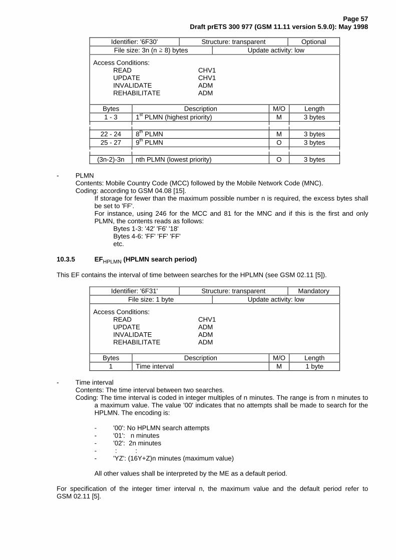
Page 57Draft prETS 300 977 (GSM 11.11 version 5.9.0): May 1998
Identifier: '6F30' Structure: transparent OptionalFile size: 3n (n � 8) bytes Update activity: low
Access Conditions:READ CHV1UPDATE CHV1INVALIDATE ADMREHABILITATE ADM
Bytes Description M/O Length1 - 3 1st PLMN (highest priority) M 3 bytes
22 - 24 8th PLMN M 3 bytes25 - 27 9th PLMN O 3 bytes
(3n-2)-3n nth PLMN (lowest priority) O 3 bytes
- PLMNContents: Mobile Country Code (MCC) followed by the Mobile Network Code (MNC).Coding: according to GSM 04.08 [15].
If storage for fewer than the maximum possible number n is required, the excess bytes shallbe set to 'FF'.For instance, using 246 for the MCC and 81 for the MNC and if this is the first and onlyPLMN, the contents reads as follows:
Bytes 1-3: '42' 'F6' '18'Bytes 4-6: 'FF' 'FF' 'FF'etc.
10.3.5 EFHPLMN (HPLMN search period)
This EF contains the interval of time between searches for the HPLMN (see GSM 02.11 [5]).
Identifier: '6F31' Structure: transparent MandatoryFile size: 1 byte Update activity: low
Access Conditions:READ CHV1UPDATE ADMINVALIDATE ADMREHABILITATE ADM
Bytes Description M/O Length1 Time interval M 1 byte
- Time intervalContents: The time interval between two searches.Coding: The time interval is coded in integer multiples of n minutes. The range is from n minutes to
a maximum value. The value '00' indicates that no attempts shall be made to search for theHPLMN. The encoding is:
- '00': No HPLMN search attempts- '01': n minutes- '02': 2n minutes- : :- 'YZ': (16Y+Z)n minutes (maximum value)
All other values shall be interpreted by the ME as a default period.
For specification of the integer timer interval n, the maximum value and the default period refer toGSM 02.11 [5].

Page 58Draft prETS 300 977 (GSM 11.11 version 5.9.0): May 1998
10.3.6 EFACMmax (ACM maximum value)
This EF contains the maximum value of the accumulated call meter. This EF shall always be allocated ifEFACM is allocated.
Identifier: '6F37' Structure: transparent OptionalFile size: 3 bytes Update activity: low
Access Conditions:READ CHV1UPDATE CHV1/CHV2
(fixed during administrative management)INVALIDATE ADMREHABILITATE ADM
Bytes Description M/O Length1 - 3 Maximum value M 3 bytes
- Maximum valueContents: maximum value of the Accumulated Call Meter (ACM)Coding:
)LUVW E\WH�¸¶¶¶¾¶¶¶¾¶¶¶¾¶¶¶¾¶¶¶¾¶¶¶¾¶¶¶¾¶¶¶¹·E� ·E� ·E� ·E� ·E� ·E� ·E� ·E� ·º¶¶¶¿¶¶¶¿¶¶¶¿¶¶¶¿¶¶¶¿¶¶¶¿¶¶¶¿¶¶¶»· · · · · · · ·��� ��� ��� ��� ��� ��� ��� ���
6HFRQG E\WH�¸¶¶¶¾¶¶¶¾¶¶¶¾¶¶¶¾¶¶¶¾¶¶¶¾¶¶¶¾¶¶¶¹·E� ·E� ·E� ·E� ·E� ·E� ·E� ·E� ·º¶¶¶¿¶¶¶¿¶¶¶¿¶¶¶¿¶¶¶¿¶¶¶¿¶¶¶¿¶¶¶»· · · · · · · ·��� ��� ��� ��� ��� ��� �� ��
7KLUG E\WH�¸¶¶¶¾¶¶¶¾¶¶¶¾¶¶¶¾¶¶¶¾¶¶¶¾¶¶¶¾¶¶¶¹·E� ·E� ·E� ·E� ·E� ·E� ·E� ·E� ·º¶¶¶¿¶¶¶¿¶¶¶¿¶¶¶¿¶¶¶¿¶¶¶¿¶¶¶¿¶¶¶»· · · · · · · ·�� �� �� �� �� �� �� ��
For instance, '00' '00' '30' represents 25+24.
All ACM data is stored in the SIM and transmitted over the SIM/ME interface as binary.
ACMmax is not valid, as defined in GSM 02.24 [7], if it is coded '000000'.

Page 59Draft prETS 300 977 (GSM 11.11 version 5.9.0): May 1998
10.3.7 EFSST (SIM service table)
This EF indicates which services are allocated, and whether, if allocated, the service is activated. If aservice is not allocated or not activated in the SIM, the ME shall not select this service.
Identifier: '6F38' Structure: transparent MandatoryFile size: X bytes, X � 2 Update activity: low
Access Conditions:READ CHV1UPDATE ADMINVALIDATE ADMREHABILITATE ADM
Bytes Description M/O Length1 Services n¡1 to n¡4 M 1 byte2 Services n¡5 to n¡8 M 1 byte3 Services n¡9 to n¡12 O 1 byte4 Services n¡13 to n¡16 O 1 byte5 Services n¡17 to n¡20 O 1 byte6 Services n¡21 to n¡24 O 1 byte7 Services n¡25 to n¡28 O 1 byte8 Services n¡29 to n¡32 O 1 byte
etc.X Services (4X-3) to (4X) O 1 byte
-ServicesContents: Service n°1 : CHV1 disable function
Service n°2 : Abbreviated Dialling Numbers (ADN)Service n°3 : Fixed Dialling Numbers (FDN)Service n°4 : Short Message Storage (SMS)Service n°5 : Advice of Charge (AoC)Service n°6 : Capability Configuration Parameters (CCP)Service n°7 : PLMN selectorService n°8 : RFUService n°9 : MSISDNService n°10: Extension1Service n°11: Extension2Service n°12: SMS ParametersService n°13: Last Number Dialled (LND)Service n°14: Cell Broadcast Message IdentifierService n°15: Group Identifier Level 1Service n°16: Group Identifier Level 2Service n°17: Service Provider NameService n°18: Service Dialling Numbers (SDN)Service n°19: Extension3Service n°20: RFUService n°21: VCGS Group Identifier List (EFVGCS and EFVGCSS)Service n°22: VBS Group Identifier List (EFVBS and EFVBSS)Service n°23: enhanced Multi-Level Precedence and Pre-emption ServiceService n°24: Automatic Answer for eMLPPService n°25: Data download via SMS-CBService n°26: Data download via SMS-PPService n°27: Menu selectionService n°28: Call controlService n°29: Proactive SIMService n°30: Cell Broadcast Message Identifier RangesService n°31: Barred Dialling Numbers (BDN)Service n°32: Extension4Service n°33: De-personalization Control KeysService n°34: Co-operative Network ListService n°35: Short Message Status Reports (if $(SMSR)$ is supported)Service n°36 Network's indication of alerting in the MS (if $(NIA)$ is supported)Service n°37 Mobile Originated Short Message control by SIM (if $(MOSMcontrol)$ is
supported)

Page 60Draft prETS 300 977 (GSM 11.11 version 5.9.0): May 1998
For a phase 2 SIM, the EF shall contain at least two bytes which correspond to the Phase 1 services.Further bytes may be included, but if the EF includes an optional byte, then it is mandatory for the EF toalso contain all bytes before that byte. Other services are possible in the future and will be coded onfurther bytes in the EF. The coding falls under the responsibility of ETSI.
NOTE 1: Service N°8 was used in Phase 1 for Called Party Subaddress. To prevent any risk ofincompatibility Service N°8 should not be reallocated.
NOTE 2: As the BDN service relies on the Call Control feature, service n°31 (BDN) should onlybe allocated and activated if service n°28 (Call control) is allocated and activated.
Coding:2 bits are used to code each service:first bit = 1: service allocatedfirst bit = 0: service not allocated
where the first bit is b1, b3, b5 or b7;second bit = 1: service activatedsecond bit = 0: service not activated
where the second bit is b2, b4, b6 or b8.
Service allocated means that the SIM has the capability to support the service. Serviceactivated means that the service is available for the card holder (only valid if the service isallocated).
The following codings are possible:- first bit = 0: service not allocated, second bit has no meaning;- first bit = 1 and second bit = 0: service allocated but not activated;- first bit = 1 and second bit = 1: service allocated and activated.
The bits for services not yet defined shall be set to RFU. For coding of RFU seesubclause 9.3.
)LUVW E\WH�¸¶¶¾¶¶¾¶¶¾¶¶¾¶¶¾¶¶¾¶¶¾¶¶¹·E�·E�·E�·E�·E�·E�·E�·E�·º¾¶¿¾¶¿¾¶¿¾¶¿¾¶¿¾¶¿¾¶¿¾¶»· · · · · · º¶¶¿¶¶ 6HUYLFH Q¡�· · · · º¶¶¿¶¶¶¶¶¶¶¶ 6HUYLFH Q¡�· · º¶¶¿¶¶¶¶¶¶¶¶¶¶¶¶¶¶ 6HUYLFH Q¡�º¶¶¿¶¶¶¶¶¶¶¶¶¶¶¶¶¶¶¶¶¶¶¶ 6HUYLFH Q¡�
6HFRQG E\WH�¸¶¶¾¶¶¾¶¶¾¶¶¾¶¶¾¶¶¾¶¶¾¶¶¹·E�·E�·E�·E�·E�·E�·E�·E�·º¾¶¿¾¶¿¾¶¿¾¶¿¾¶¿¾¶¿¾¶¿¾¶»· · · · · · º¶¶¿¶¶ 6HUYLFH Q¡�· · · · º¶¶¿¶¶¶¶¶¶¶¶ 6HUYLFH Q¡�· · º¶¶¿¶¶¶¶¶¶¶¶¶¶¶¶¶¶ 6HUYLFH Q¡�º¶¶¿¶¶¶¶¶¶¶¶¶¶¶¶¶¶¶¶¶¶¶¶ 6HUYLFH Q¡�
etc.
The following example of coding for the first byte means that service n°1 "CHV1-Disabling" isallocated but not activated:¸¶¶¾¶¶¾¶¶¾¶¶¾¶¶¾¶¶¾¶¶¾¶¶¹·E�·E�·E�·E�·E�·E�·E�·E�·º¾¶¿¾¶¿¾¶¿¾¶¿¾¶¿¾¶¿¾¶¿¾¶»; ; ; ; ; ; � �
If the SIM supports the FDN feature (FDN allocated and activated) a special mechanism shall exist in theSIM which invalidates both EFIMSI and EFLOCI once during each GSM session. This mechanism shall beinvoked by the SIM automatically if FDN is enabled. This invalidation shall occur at least before the nextcommand following selection of either EF. FDN is enabled when the ADN is invalidated or not activated.
If the SIM supports the BDN feature (BDN allocated and activated) a special mechanism shall exist in theSIM which invalidates both EFIMSI and EFLOCI once during each GSM session and which forbids theREHABILITATE command to rehabilitate both EFIMSI and EFLOCI until the PROFILE DOWNLOADprocedure is performed indicating that the ME supports the "Call control by SIM" facility. This mechanism

Page 61Draft prETS 300 977 (GSM 11.11 version 5.9.0): May 1998
shall be invoked by the SIM automatically if BDN is enabled. The invalidation of EFIMSI and EFLOCI shalloccur at least before the next command following selection of either EF. BDN is enabled when the EFBDNis not invalidated.
10.3.8 EFACM (Accumulated call meter)
This EF contains the total number of units for both the current call and the preceding calls.
NOTE: The information may be used to provide an indication to the user for advice or as abasis for the calculation of the monetary cost of calls (see GSM 02.86 [9]).
Identifier: '6F39' Structure: cyclic OptionalRecord length: 3 bytes Update activity: high
Access Conditions:READ CHV1UPDATE CHV1/CHV2
(fixed during administrative management)INCREASE CHV1INVALIDATE ADMREHABILITATE ADM
Bytes Description M/O Length1 - 3 Accumulated count of units M 3 bytes
- Accumulated count of unitsContents: value of the ACMCoding: see the coding of EFACMmax
10.3.9 EFGID1 (Group Identifier Level 1)
This EF contains identifiers for particular SIM-ME associations. It can be used to identify a group of SIMsfor a particular application.
Identifier: '6F3E' Structure: transparent OptionalFile size: 1-n bytes Update activity: low
Access Conditions:READ CHV1UPDATE ADMINVALIDATE ADMREHABILITATE ADM
Bytes Description M/O Length1 - n SIM group identifier(s) O n bytes
10.3.10 EFGID2 (Group Identifier Level 2)
This EF contains identifiers for particular SIM-ME associations. It can be used to identify a group of SIMsfor a particular application.
Identifier: '6F3F' Structure: transparent OptionalFile size: 1-n bytes Update activity: low
Access Conditions:READ CHV1UPDATE ADMINVALIDATE ADMREHABILITATE ADM
Bytes Description M/O Length1 - n SIM group identifier(s) O n bytes

Page 62Draft prETS 300 977 (GSM 11.11 version 5.9.0): May 1998
NOTE: The structure of EFGID1 and EFGID2 are identical. They are provided to allow thenetwork operator to enforce different levels of security dependant on application.
10.3.11 EFSPN (Service Provider Name)
This EF contains the service provider name and appropriate requirements for the display by the ME.
Identifier: '6F46' Structure: transparent OptionalFile Size: 17 bytes Update activity: low
Access Conditions:READ ALWAYSUPDATE ADMINVALIDATE ADMREHABILITATE ADM
Bytes Description M/O Length1 Display Condition M 1 byte
2 - 17 Service Provider Name M 16 bytes
- Display ConditionContents: display condition for the service provider name in respect to the registered PLMN (see
GSM 02.07 [3]).Coding: see below
Byte 1:Bit b1
0 : display of registered PLMN not required1 : display of registered PLMN required
Bits b2 to b8 are RFU (see subclause 9.3)
- Service Provider NameContents: service provider string to be displayedCoding: the string shall use either- the SMS default 7-bit coded alphabet as defined in GSM 03.38 [12] with bit 8 set to 0. The
string shall be left justified. Unused bytes shall be set to 'FF'. or, if $(UCS2)$ is supported,
- one of the UCS2 code options defined in Annex B.
10.3.12 EFPUCT (Price per unit and currency table)
This EF contains the Price per Unit and Currency Table (PUCT). The PUCT is Advice of Charge relatedinformation which may be used by the ME in conjunction with EFACM to compute the cost of calls in thecurrency chosen by the subscriber, as specified in GSM 02.24 [7]. This EF shall always be allocated ifEFACM is allocated.
Identifier: '6F41' Structure: transparent OptionalFile size: 5 bytes Update activity: low
Access Conditions:READ CHV1UPDATE CHV1/CHV2
(fixed during administrative management)INVALIDATE ADMREHABILITATE ADM
Bytes Description M/O Length1 - 3 Currency code M 3 bytes4 - 5 Price per unit M 2 bytes

Page 63Draft prETS 300 977 (GSM 11.11 version 5.9.0): May 1998
- Currency codeContents: the alpha-identifier of the currency code.Coding: bytes 1, 2 and 3 are the respective first, second and third character of the alpha identifier.
This alpha-tagging shall use the SMS default 7-bit coded alphabet as defined inGSM 03.38 [12] with bit 8 set to 0.
- Price per unitContents: price per unit expressed in the currency coded by bytes 1-3.Coding: Byte 4 and bits b1 to b4 of byte 5 represent the Elementary Price per Unit (EPPU) in the
currency coded by bytes 1-3. Bits b5 to b8 of byte 5 are the decimal logarithm of themultiplicative factor represented by the absolute value of its decimal logarithm (EX) and thesign of EX, which is coded 0 for a positive sign and 1 for a negative sign.
%\WH ��¸¶¶¶¾¶¶¶¾¶¶¶¾¶¶¶¾¶¶¶¾¶¶¶¾¶¶¶¾¶¶¶¹·E� ·E� ·E� ·E� ·E� ·E� ·E� ·E� ·º¶¶¶¿¶¶¶¿¶¶¶¿¶¶¶¿¶¶¶¿¶¶¶¿¶¶¶¿¶¶¶»· · · · · · · ·��� ��� �� �� �� �� �� �� RI (338
%\WH ��¸¶¶¶¾¶¶¶¾¶¶¶¾¶¶¶¾¶¶¶¾¶¶¶¾¶¶¶¾¶¶¶¹·E� ·E� ·E� ·E� ·E� ·E� ·E� ·E� ·º¶¶¶¿¶¶¶¿¶¶¶¿¶¶¶¿¶¶¶¿¶¶¶¿¶¶¶¿¶¶¶»· · · · · · · ·· · · · �� �� �� �� RI (338· · · º¶¶¶¶¶¶¶¶¶¶¶¶¶¶¶¶¶¶¶ 6LJQ RI (;· · º¶¶¶¶¶¶¶¶¶¶¶¶¶¶¶¶¶¶¶¶¶¶¶ �� RI $EV�(;�· º¶¶¶¶¶¶¶¶¶¶¶¶¶¶¶¶¶¶¶¶¶¶¶¶¶¶¶ �� RI $EV�(;�º¶¶¶¶¶¶¶¶¶¶¶¶¶¶¶¶¶¶¶¶¶¶¶¶¶¶¶¶¶¶¶ �� RI $EV�(;�
The computation of the price per unit value is made by the ME in compliance withGSM 02.24 [7] by the following formula:
price per unit = EPPU * 10EX.The price has to be understood as expressed in the coded currency.
10.3.13 EFCBMI (Cell broadcast message identifier selection)
This EF contains the Message Identifier Parameters which specify the type of content of the cell broadcastmessages that the subscriber wishes the MS to accept.
Any number of CB Message Identifier Parameters may be stored in the SIM. No order of priority isapplicable.
Identifier: '6F45' Structure: transparent OptionalFile size: 2n bytes Update activity: low
Access Conditions:READ CHV1UPDATE CHV1INVALIDATE ADMREHABILITATE ADM
Bytes Description M/O Length1 - 2 CB Message Identifier 1 O 2 bytes3 - 4 CB Message Identifier 2 O 2 bytes
2n-1 - 2n CB Message Identifier n O 2 bytes
- Cell Broadcast Message IdentifierCoding: as in GSM 03.41, "Message Format on BTS-MS Interface - Message Identifier".
Values listed show the types of message which shall be accepted by the MS.Unused entries shall be set to 'FF FF'.

Page 64Draft prETS 300 977 (GSM 11.11 version 5.9.0): May 1998
10.3.14 EFBCCH (Broadcast control channels)
This EF contains information concerning the BCCH according to GSM 04.08 [15].
BCCH storage may reduce the extent of a Mobile Station's search of BCCH carriers when selecting a cell.The BCCH carrier lists in an MS shall be in accordance with the procedures specified in GSM 04.08 [15].The MS shall only store BCCH information from the System Information 2 message and not the 2bisextension message.
Identifier: '6F74' Structure: transparent MandatoryFile size: 16 bytes Update activity: high
Access Conditions:READ CHV1UPDATE CHV1INVALIDATE ADMREHABILITATE ADM
Bytes Description M/O Length1 - 16 BCCH information M 16 bytes
- BCCH informationCoding: The information is coded as octets 2-17 of the "neighbour cells description information
element" in GSM 04.08 [15].
10.3.15 EFACC (Access control class)
This EF contains the assigned access control class(es). GSM 02.11 [5] refers. The access control class isa parameter to control the RACH utilization. 15 classes are split into 10 classes randomly allocated tonormal subscribers and 5 classes allocated to specific high priority users. For more information seeGSM 02.11 [5].
Identifier: '6F78' Structure: transparent MandatoryFile size: 2 bytes Update activity: low
Access Conditions:READ CHV1UPDATE ADMINVALIDATE ADMREHABILITATE ADM
Bytes Description M/O Length1 - 2 Access control classes M 2 bytes
- Access control classesCoding: Each ACC is coded on one bit. An ACC is "allocated" if the corresponding bit is set to 1 and
"not allocated" if this bit is set to 0. Bit b3 of byte 1 is set to 0.
Byte 1:
¸¶¶¾¶¶¾¶¶¾¶¶¾¶¶¾¶¶¾¶¶¾¶¶¹·E�·E�·E�·E�·E�·E�·E�·E�·º¾¶¿¾¶¿¾¶¿¾¶¿¾¶¿¾¶¿¾¶¿¾¶»�� �� �� �� �� �� �� �� 1XPEHU RI WKH $&& �H[FHSW IRU ELW E��
%\WH ��¸¶¶¾¶¶¾¶¶¾¶¶¾¶¶¾¶¶¾¶¶¾¶¶¹·E�·E�·E�·E�·E�·E�·E�·E�·º¾¶¿¾¶¿¾¶¿¾¶¿¾¶¿¾¶¿¾¶¿¾¶»�� �� �� �� �� �� �� �� 1XPEHU RI WKH $&&
10.3.16 EFFPLMN (Forbidden PLMNs)
This EF contains the coding for four Forbidden PLMNs (FPLMN). It is read by the ME as part of the SIMinitialization procedure and indicates PLMNs which the MS shall not automatically attempt to access.

Page 65Draft prETS 300 977 (GSM 11.11 version 5.9.0): May 1998
A PLMN is written to the EF if a network rejects a Location Update with the cause "PLMN not allowed".The ME shall manage the list as follows.
When four FPLMNs are held in the EF, and rejection of a further PLMN is received by the ME from thenetwork, the ME shall modify the EF using the UPDATE command. This new PLMN shall be stored in thefourth position, and the existing list "shifted" causing the previous contents of the first position to be lost.
When less than four FPLMNs exist in the EF, storage of an additional FPLMN shall not cause any existingFPLMN to be lost.
Dependent upon procedures used to manage storage and deletion of FPLMNs in the EF, it is possible,when less than four FPLMNs exist in the EF, for 'FFFFFF' to occur in any position. The ME shall analyseall the EF for FPLMNs in any position, and not regard 'FFFFFF' as a termination of valid data.
Identifier: '6F7B' Structure: transparent MandatoryFile size: 12 bytes Update activity: low
Access Conditions:READ CHV1UPDATE CHV1INVALIDATE ADMREHABILITATE ADM
Bytes Description M/O Length1 - 3 PLMN 1 M 3 bytes4 - 6 PLMN 2 M 3 bytes7 - 9 PLMN 3 M 3 bytes
10 - 12 PLMN 4 M 3 bytes
- PLMNContents: Mobile Country Code (MCC) followed by the Mobile Network Code (MNC).Coding: according to GSM 04.08 [15].
For instance, using 246 for the MCC and 81 for the MNC and if this is stored in PLMN 3 thecontents is as follows:
Bytes 7-9: '42' 'F6' '18'If storage for fewer than 4 PLMNs is required, the unused bytes shall be set to 'FF'.
10.3.17 EFLOCI (Location information)
This EF contains the following Location Information:
- Temporary Mobile Subscriber Identity (TMSI)- Location Area Information (LAI)- TMSI TIME- Location update status
Identifier: '6F7E' Structure: transparent MandatoryFile size: 11 bytes Update activity: high
Access Conditions:READ CHV1UPDATE CHV1INVALIDATE ADMREHABILITATE CHV1
Bytes Description M/O Length1 - 4 TMSI M 4 bytes5 - 9 LAI M 5 bytes10 TMSI TIME M 1 byte11 Location update status M 1 byte

Page 66Draft prETS 300 977 (GSM 11.11 version 5.9.0): May 1998
- TMSIContents: Temporary Mobile Subscriber IdentityCoding: according to GSM 04.08 [15].
%\WH �� ILUVW E\WH RI 706,¸¶¶¾¶¶¾¶¶¾¶¶¾¶¶¾¶¶¾¶¶¾¶¶¹·E�·E�·E�·E�·E�·E�·E�·E�·º¾¶¿¾¶¿¾¶¿¾¶¿¾¶¿¾¶¿¾¶¿¾¶»06%
- LAIContents: Location Area InformationCoding: according to GSM 04.08 [15].
%\WH �� ILUVW E\WH RI /$, �0&&�¸¶¶¾¶¶¾¶¶¾¶¶¾¶¶¾¶¶¾¶¶¾¶¶¹·E�·E�·E�·E�·E�·E�·E�·E�·º¾¶¿¾¶¿¾¶¿¾¶¿¾¶¿¾¶¿¾¶¿¾¶»· · · · · · · º¶¶ /6% RI 0&& 'LJLW �· · · · · · º¶¶¶¶¶ �· · · · · º¶¶¶¶¶¶¶¶ �· · · · º¶¶¶¶¶¶¶¶¶¶¶ 06% RI 0&& 'LJLW �· · · º¶¶¶¶¶¶¶¶¶¶¶¶¶¶ /6% RI 0&& 'LJLW �· · º¶¶¶¶¶¶¶¶¶¶¶¶¶¶¶¶¶ �· º¶¶¶¶¶¶¶¶¶¶¶¶¶¶¶¶¶¶¶¶ �º¶¶¶¶¶¶¶¶¶¶¶¶¶¶¶¶¶¶¶¶¶¶¶ 06% RI 0&& 'LJLW �
%\WH �� VHFRQG E\WH RI /$, �0&& FRQWLQXHG�¸¶¶¾¶¶¾¶¶¾¶¶¾¶¶¾¶¶¾¶¶¾¶¶¹·E�·E�·E�·E�·E�·E�·E�·E�·º¾¶¿¾¶¿¾¶¿¾¶¿¾¶¿¾¶¿¾¶¿¾¶»· · · · · · · º¶¶ /6% RI 0&& 'LJLW �· · · · · · º¶¶¶¶¶ �· · · · · º¶¶¶¶¶¶¶¶ �· · · · º¶¶¶¶¶¶¶¶¶¶¶ 06% RI 0&& 'LJLW �º¶¶¿¶¶¿¶¶¿¶¶¶¶¶¶¶¶¶¶¶¶¶¶ ELWV E� WR E� DUH �
%\WH �� WKLUG E\WH RI /$, �01&�¸¶¶¾¶¶¾¶¶¾¶¶¾¶¶¾¶¶¾¶¶¾¶¶¹·E�·E�·E�·E�·E�·E�·E�·E�·º¾¶¿¾¶¿¾¶¿¾¶¿¾¶¿¾¶¿¾¶¿¾¶»· · · · · · · º¶¶ /6% RI 01& 'LJLW �· · · · · · º¶¶¶¶¶ �· · · · · º¶¶¶¶¶¶¶¶ �· · · · º¶¶¶¶¶¶¶¶¶¶¶ 06% RI 01& 'LJLW �· · · º¶¶¶¶¶¶¶¶¶¶¶¶¶¶ /6% RI 01& 'LJLW �· · º¶¶¶¶¶¶¶¶¶¶¶¶¶¶¶¶¶ �· º¶¶¶¶¶¶¶¶¶¶¶¶¶¶¶¶¶¶¶¶ �º¶¶¶¶¶¶¶¶¶¶¶¶¶¶¶¶¶¶¶¶¶¶¶ 06% RI 01& 'LJLW �
Byte 8: fourth byte of LAI (LAC)Byte 9: fifth byte of LAI (LAC continued)
- TMSI TIMEContents: Current value of Periodic Location Updating Timer (T3212).
This byte is used by Phase 1 MEs, but it shall not be used by Phase 2 MEs.
- Location update statusContents: status of location update according to GSM 04.08 [15].Coding:
Byte 11:Bits: b3 b2 b1
0 0 0 : updated0 0 1 : not updated0 1 0 : PLMN not allowed0 1 1 : Location Area not allowed1 1 1 : reserved
Bits b4 to b8 are RFU (see subclause 9.3).

Page 67Draft prETS 300 977 (GSM 11.11 version 5.9.0): May 1998
10.3.18 EFAD (Administrative data)
This EF contains information concerning the mode of operation according to the type of SIM, such asnormal (to be used by PLMN subscribers for GSM operations), type approval (to allow specific use of theME during type approval procedures of e.g. the radio equipment), cell testing (to allow testing of a cellbefore commercial use of this cell), manufacturer specific (to allow the ME manufacturer to performspecific proprietary auto-test in its ME during e.g. maintenance phases).
It also provides an indication of whether some ME features should be activated during normal operation.
Identifier: '6FAD' Structure: transparent MandatoryFile size: 3+X bytes Update activity: low
Access Conditions:READ ALWUPDATE ADMINVALIDATE ADMREHABILITATE ADM
Bytes Description M/O Length1 MS operation mode M 1 byte
2 - 3 Additional information M 2 bytes4 - 3+X RFU O X bytes
- MS operation modeContents: mode of operation for the MSCoding:
Initial value- normal operation '00'- type approval operations '80'- normal operation + specific facilities '01'- type approval operations + specific facilities '81'- maintenance (off line) '02'- cell test operation '04'
- Additional informationCoding:
- specific facilities (if b1=1 in byte 1);
Byte 2 (first byte of additional information):¸¶¶¾¶¶¾¶¶¾¶¶¾¶¶¾¶¶¾¶¶¾¶¶¹·E�·E�·E�·E�·E�·E�·E�·E�·º¾¶¿¾¶¿¾¶¿¾¶¿¾¶¿¾¶¿¾¶¿¾¶»· · · · · · · º¶¶ 5)8· · · · · · º¶¶¶¶¶ �· · · · · º¶¶¶¶¶¶¶¶ �· · · · º¶¶¶¶¶¶¶¶¶¶¶ �· · · º¶¶¶¶¶¶¶¶¶¶¶¶¶¶ �· · º¶¶¶¶¶¶¶¶¶¶¶¶¶¶¶¶¶ �· º¶¶¶¶¶¶¶¶¶¶¶¶¶¶¶¶¶¶¶¶ �º¶¶¶¶¶¶¶¶¶¶¶¶¶¶¶¶¶¶¶¶¶¶¶ �
Byte 3:¸¶¶¾¶¶¾¶¶¾¶¶¾¶¶¾¶¶¾¶¶¾¶¶¹·E�·E�·E�·E�·E�·E�·E�·E�·º¾¶¿¾¶¿¾¶¿¾¶¿¾¶¿¾¶¿¾¶¿¾¶»· · · · · · · º¶¶ 2)0 ¶¶¾¶ � 2)0 WR EH GLVDEOHG E\ WKH 0(· · · · · · º¶¶¶¶¶ 5)8 º¶ � 2)0 WR EH DFWLYDWHG E\ WKH 0(· · · · · º¶¶¶¶¶¶¶¶ �· · · · º¶¶¶¶¶¶¶¶¶¶¶ �· · · º¶¶¶¶¶¶¶¶¶¶¶¶¶¶ �· · º¶¶¶¶¶¶¶¶¶¶¶¶¶¶¶¶¶ �· º¶¶¶¶¶¶¶¶¶¶¶¶¶¶¶¶¶¶¶¶ �º¶¶¶¶¶¶¶¶¶¶¶¶¶¶¶¶¶¶¶¶¶¶¶ �
- ME manufacturer specific information (if b2=1 in byte 1).

Page 68Draft prETS 300 977 (GSM 11.11 version 5.9.0): May 1998
10.3.19 EFPhase (Phase identification)
This EF contains information concerning the phase of the SIM.
Identifier: '6FAE' Structure: transparent MandatoryFile size: 1 byte Update activity: low
Access Conditions:READ ALWUPDATE ADMINVALIDATE ADMREHABILITATE ADM
Bytes Description M/O Length1 SIM Phase M 1 byte
- SIM PhaseCoding:
'00' : phase 1'02' : phase 2'03' : phase 2 and PROFILE DOWNLOAD required (see GSM 11.14 [27]).All other codings are reserved for specification by ETSI TC SMG. Codings '04' to '0F' indicatethat the SIM supports, as a minimum, the mandatory requirements defined in thisspecification.
This phase identification does not preclude a SIM to support some features of a phase later than the oneindicated in EFPhase. For example : if EFPhase is coded '00', it may be assumed by the ME that somePhase 2 or Phase 2+ features are supported by this SIM; if EFPhase is coded '02' or '03', it may beassumed by the ME that some Phase 2+ features are supported by this SIM.
However, the services n°3 (FDN) and/or n°5 (AoC) shall only be allocated and activated in SIMs ofphase 2 or later with EFPhase being coded '02' or greater. Similarly, service n°31 (BDN) shall only beallocated and activated in SIMs with EFPhase being coded '03' or greater.
If EFPhase is coded '03' or greater, an ME supporting SIM Application Toolkit shall perform the PROFILEDOWNLOAD procedure, as defined in GSM 11.14 [27].
10.3.20 EFVGCS (Voice Group Call Service)
This EF contains a list of those VGCS group identifiers the user has subscribed to. The elementary file isused by the ME for group call establishment and group call reception.
Identifier: '6FB1' Structure: transparent OptionalFile size: 4n bytes (n <= 50) Update activity: low
Access Conditions:READ CHV1UPDATE ADMINVALIDATE ADMREHABILITATE ADM
Bytes Description M/O Length1 - 4 Group ID 1 M 4 bytes5 - 8 Group ID 2 O 4 bytes
: : : :(4n-3)-4n Group ID n O 4 bytes
- Group IDContents: VGCS Group IdCoding: according to GSM 03.03 [10]
If storage for fewer than the maximum possible number of n is required, the excess bytesshall be set to 'FF'.
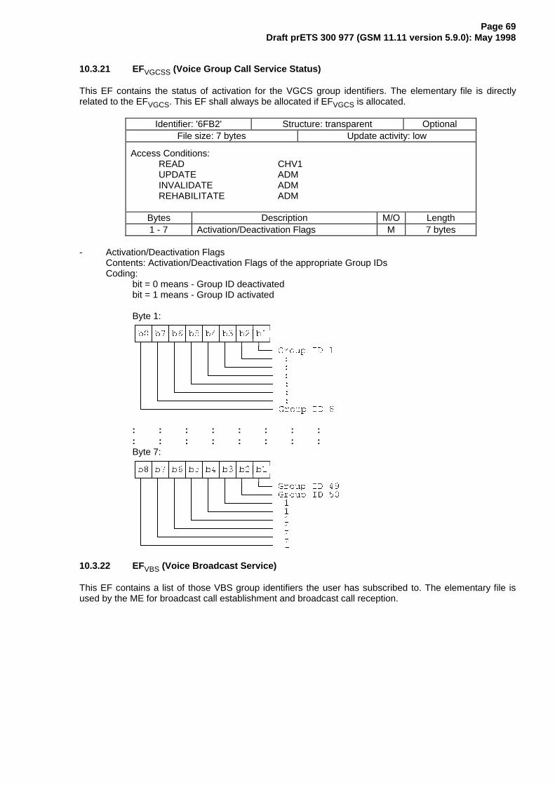
Page 69Draft prETS 300 977 (GSM 11.11 version 5.9.0): May 1998
10.3.21 EFVGCSS (Voice Group Call Service Status)
This EF contains the status of activation for the VGCS group identifiers. The elementary file is directlyrelated to the EFVGCS. This EF shall always be allocated if EFVGCS is allocated.
Identifier: '6FB2' Structure: transparent OptionalFile size: 7 bytes Update activity: low
Access Conditions:READ CHV1UPDATE ADMINVALIDATE ADMREHABILITATE ADM
Bytes Description M/O Length1 - 7 Activation/Deactivation Flags M 7 bytes
- Activation/Deactivation FlagsContents: Activation/Deactivation Flags of the appropriate Group IDsCoding:
bit = 0 means - Group ID deactivatedbit = 1 means - Group ID activated
Byte 1:¸¶¶¾¶¶¾¶¶¾¶¶¾¶¶¾¶¶¾¶¶¾¶¶¹·E�·E�·E�·E�·E�·E�·E�·E�·º¾¶¿¾¶¿¾¶¿¾¶¿¾¶¿¾¶¿¾¶¿¾¶»· · · · · · · º¶¶ *URXS ,' �· · · · · · º¶¶¶¶¶ �· · · · · º¶¶¶¶¶¶¶¶ �· · · · º¶¶¶¶¶¶¶¶¶¶¶ �· · · º¶¶¶¶¶¶¶¶¶¶¶¶¶¶ �· · º¶¶¶¶¶¶¶¶¶¶¶¶¶¶¶¶¶ �· º¶¶¶¶¶¶¶¶¶¶¶¶¶¶¶¶¶¶¶¶ �º¶¶¶¶¶¶¶¶¶¶¶¶¶¶¶¶¶¶¶¶¶¶¶ *URXS ,' �
: : : : : : : :: : : : : : : :Byte 7:¸¶¶¾¶¶¾¶¶¾¶¶¾¶¶¾¶¶¾¶¶¾¶¶¹·E�·E�·E�·E�·E�·E�·E�·E�·º¾¶¿¾¶¿¾¶¿¾¶¿¾¶¿¾¶¿¾¶¿¾¶»· · · · · · · º¶¶ *URXS ,' ��· · · · · · º¶¶¶¶¶ *URXS ,' ��· · · · · º¶¶¶¶¶¶¶¶ �· · · · º¶¶¶¶¶¶¶¶¶¶¶ �· · · º¶¶¶¶¶¶¶¶¶¶¶¶¶¶ �· · º¶¶¶¶¶¶¶¶¶¶¶¶¶¶¶¶¶ �· º¶¶¶¶¶¶¶¶¶¶¶¶¶¶¶¶¶¶¶¶ �º¶¶¶¶¶¶¶¶¶¶¶¶¶¶¶¶¶¶¶¶¶¶¶ �
10.3.22 EFVBS (Voice Broadcast Service)
This EF contains a list of those VBS group identifiers the user has subscribed to. The elementary file isused by the ME for broadcast call establishment and broadcast call reception.

Page 70Draft prETS 300 977 (GSM 11.11 version 5.9.0): May 1998
Identifier: '6FB3' Structure: transparent OptionalFile size: 4n bytes (n <= 50) Update activity: low
Access Conditions:READ CHV1UPDATE ADMINVALIDATE ADMREHABILITATE ADM
Bytes Description M/O Length1 - 4 Group ID 1 M 4 bytes5 - 2 Group ID 2 O 4 bytes
: : : :(4n-3)-4n Group ID n O 4 bytes
- Group IDContents: VBS Group IdCoding: according to GSM 03.03 [10]
If storage for fewer than the maximum possible number of n is required, the excess bytesshall be set to 'FF'.
10.3.23 EFVBSS (Voice Broadcast Service Status)
This EF contains the status of activation for the VBS group identifiers. The elementary file is directlyrelated to the EFVBS. This EF shall always be allocated if EFVBS is allocated.
Identifier: '6FB4' Structure: transparent OptionalFile size: 7 bytes Update activity: low
Access Conditions:READ CHV1UPDATE ADMINVALIDATE ADMREHABILITATE ADM
Bytes Description M/O Length1 - 7 Activation/Deactivation Flags M 7 bytes
- Activation/Deactivation FlagsContents: Activation/Deactivation Flags of the appropriate Group IDsCoding:
see coding of EFVGCS
10.3.24 EFeMLPP (enhanced Multi Level Pre-emption and Priority)
This EF contains information about priority levels and fast call set-up conditions for the enhanced MultiLevel Pre-emption and Priority service that which can be used by the subscriber.
Identifier: '6FB5' Structure: transparent OptionalFile size: 2 bytes Update activity: low
Access Conditions:READ CHV1UPDATE ADMINVALIDATE ADMREHABILITATE ADM
Bytes Description M/O Length1 Priority levels M 1 byte2 Fast call set-up conditions M 1 byte

Page 71Draft prETS 300 977 (GSM 11.11 version 5.9.0): May 1998
- Priority levelsContents: The eMLPP priority levels subscribed to.Coding: Each eMLPP priority level is coded on one bit. Priority levels subscribed to have their
corresponding bits set to 1. Priority levels not subscribed to have their corresponding bits setto 0. Bit b8 is reserved and set to 0.
Byte 1:¸¶¶¾¶¶¾¶¶¾¶¶¾¶¶¾¶¶¾¶¶¾¶¶¹·E�·E�·E�·E�·E�·E�·E�·E�·º¾¶¿¾¶¿¾¶¿¾¶¿¾¶¿¾¶¿¾¶¿¾¶»· · · · · · · º¶¶ SULRULW\ OHYHO $· · · · · · º¶¶¶¶¶ SULRULW\ OHYHO %· · · · · º¶¶¶¶¶¶¶¶ SULRULW\ OHYHO �· · · · º¶¶¶¶¶¶¶¶¶¶¶ SULRULW\ OHYHO �· · · º¶¶¶¶¶¶¶¶¶¶¶¶¶¶ SULRULW\ OHYHO �· · º¶¶¶¶¶¶¶¶¶¶¶¶¶¶¶¶¶ SULRULW\ OHYHO �· º¶¶¶¶¶¶¶¶¶¶¶¶¶¶¶¶¶¶¶¶ SULRULW\ OHYHO �º¶¶¶¶¶¶¶¶¶¶¶¶¶¶¶¶¶¶¶¶¶¶¶ �
Example: If priority levels B and 2 are subscribed to, EFeMLPP shall be coded '12'.
- Fast call set-up conditionsContents: For each eMLPP priority level, the capability to use a fast call set-up procedure.Coding: Each eMLPP priority level is coded on one bit. Priority levels for which fast call set-up is
allowed have their corresponding bits set to 1. Priority levels for which fast call set-up is notallowed have their corresponding bits set to 0. Bit b8 is reserved and set to 0.
Byte 2:¸¶¶¾¶¶¾¶¶¾¶¶¾¶¶¾¶¶¾¶¶¾¶¶¹·E�·E�·E�·E�·E�·E�·E�·E�·º¾¶¿¾¶¿¾¶¿¾¶¿¾¶¿¾¶¿¾¶¿¾¶» IDVW FDOO VHW�XS FRQGLWLRQ IRU· · · · · · · º¶¶ SULRULW\ OHYHO $· · · · · · º¶¶¶¶¶ SULRULW\ OHYHO %· · · · · º¶¶¶¶¶¶¶¶ SULRULW\ OHYHO �· · · · º¶¶¶¶¶¶¶¶¶¶¶ SULRULW\ OHYHO �· · · º¶¶¶¶¶¶¶¶¶¶¶¶¶¶ SULRULW\ OHYHO �· · º¶¶¶¶¶¶¶¶¶¶¶¶¶¶¶¶¶ SULRULW\ OHYHO �· º¶¶¶¶¶¶¶¶¶¶¶¶¶¶¶¶¶¶¶¶ SULRULW\ OHYHO �º¶¶¶¶¶¶¶¶¶¶¶¶¶¶¶¶¶¶¶¶¶¶¶ �
Example: If fast call set-up is allowed for priority levels B, 0 and 2, then byte 2 of EFeMLPP iscoded '16'.
10.3.25 EFAAeM (Automatic Answer for eMLPP Service)
This EF contains those priority levels (of the Multi Level Pre-emption and Priority service) for which themobile station shall answer automatically to incoming calls.
Identifier: '6FB6' Structure: transparent OptionalFile size: 1 byte Update activity: low
Access Conditions:READ CHV1UPDATE CHV1INVALIDATE ADMREHABILITATE ADM
Bytes Description M/O Length1 Automatic answer priority levels M 1 byte
- Automatic answer priority levelsContents: For each eMLPP priority level, the capability for the mobile station to answer
automatically to incoming calls (with the corresponding eMLPP priority level).Coding: Each eMLPP priority level is coded on one bit. Priority levels allowing an automatic answer
from the mobile station have their corresponding bits set to 1. Priority levels not allowing anautomatic answer from the mobile station have their corresponding bits set to 0. Bit b8 isreserved and set to 0.
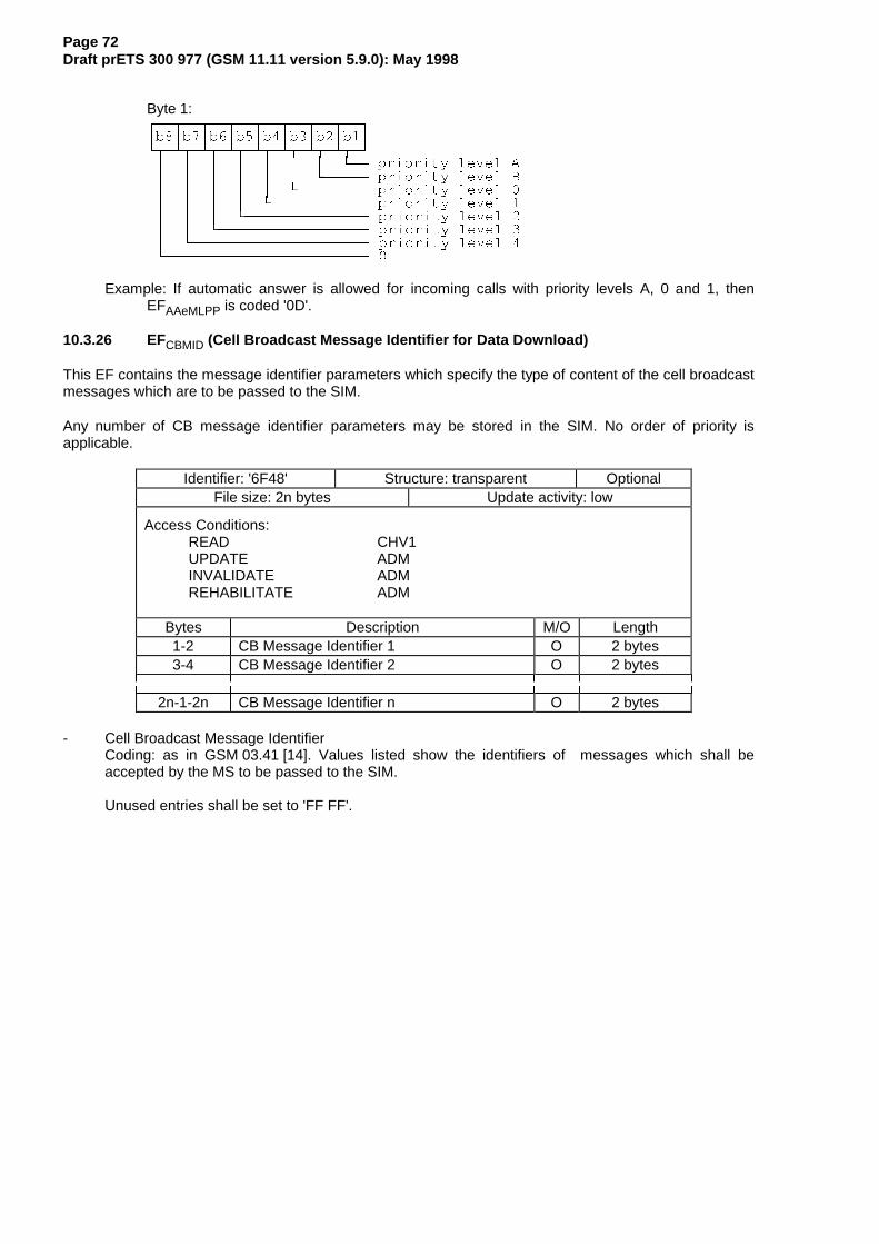
Page 72Draft prETS 300 977 (GSM 11.11 version 5.9.0): May 1998
Byte 1:¸¶¶¾¶¶¾¶¶¾¶¶¾¶¶¾¶¶¾¶¶¾¶¶¹·E�·E�·E�·E�·E�·E�·E�·E�·º¾¶¿¾¶¿¾¶¿¾¶¿¾¶¿¾¶¿¾¶¿¾¶»· · · · · · · º¶¶ SULRULW\ OHYHO $· · · · · · º¶¶¶¶¶ SULRULW\ OHYHO %· · · · · º¶¶¶¶¶¶¶¶ SULRULW\ OHYHO �· · · · º¶¶¶¶¶¶¶¶¶¶¶ SULRULW\ OHYHO �· · · º¶¶¶¶¶¶¶¶¶¶¶¶¶¶ SULRULW\ OHYHO �· · º¶¶¶¶¶¶¶¶¶¶¶¶¶¶¶¶¶ SULRULW\ OHYHO �· º¶¶¶¶¶¶¶¶¶¶¶¶¶¶¶¶¶¶¶¶ SULRULW\ OHYHO �º¶¶¶¶¶¶¶¶¶¶¶¶¶¶¶¶¶¶¶¶¶¶¶ �
Example: If automatic answer is allowed for incoming calls with priority levels A, 0 and 1, thenEFAAeMLPP is coded '0D'.
10.3.26 EFCBMID (Cell Broadcast Message Identifier for Data Download)
This EF contains the message identifier parameters which specify the type of content of the cell broadcastmessages which are to be passed to the SIM.
Any number of CB message identifier parameters may be stored in the SIM. No order of priority isapplicable.
Identifier: '6F48' Structure: transparent OptionalFile size: 2n bytes Update activity: low
Access Conditions:READ CHV1UPDATE ADMINVALIDATE ADMREHABILITATE ADM
Bytes Description M/O Length1-2 CB Message Identifier 1 O 2 bytes3-4 CB Message Identifier 2 O 2 bytes
2n-1-2n CB Message Identifier n O 2 bytes
- Cell Broadcast Message IdentifierCoding: as in GSM 03.41 [14]. Values listed show the identifiers of messages which shall beaccepted by the MS to be passed to the SIM.
Unused entries shall be set to 'FF FF'.

Page 73Draft prETS 300 977 (GSM 11.11 version 5.9.0): May 1998
10.3.27 EFECC (Emergency Call Codes)
This EF contains up to 5 emergency call codes.
Identifier: '6FB7' Structure: transparent OptionalFile size: 3n (n ≤ 5) bytes Update activity: low
Access Conditions:READ ALWUPDATE ADMINVALIDATE ADMREHABILITATE ADM
Bytes Description M/O Length1 - 3 Emergency Call Code 1 O 3 bytes4 - 6 Emergency Call Code 2 O 3 bytes
(3n-2) - 3n Emergency Call Code n O 3 bytes
- Emergency Call CodeContents: Emergency Call CodeCoding: The emergency call code is of a variable length with a maximum length of 6 digits. Each
emergency call code is coded on three bytes, with each digit within the code being coded onfour bits as shown below. If a code of less that 6 digits is chosen, then the unused nibblesshall be set to 'F'.
Byte 1:¸¶¶¾¶¶¾¶¶¾¶¶¾¶¶¾¶¶¾¶¶¾¶¶¹·E�·E�·E�·E�·E�·E�·E�·E�·º¾¶¿¾¶¿¾¶¿¾¶¿¾¶¿¾¶¿¾¶¿¾¶»· · · · · · · º¶¶ /6% RI 'LJLW �· · · · · · º¶¶¶¶¶ �· · · · · º¶¶¶¶¶¶¶¶ �· · · · º¶¶¶¶¶¶¶¶¶¶¶ 06% RI 'LJLW �· · · º¶¶¶¶¶¶¶¶¶¶¶¶¶¶ /6% RI 'LJLW �· · º¶¶¶¶¶¶¶¶¶¶¶¶¶¶¶¶¶ �· º¶¶¶¶¶¶¶¶¶¶¶¶¶¶¶¶¶¶¶¶ �º¶¶¶¶¶¶¶¶¶¶¶¶¶¶¶¶¶¶¶¶¶¶¶ 06% RI 'LJLW �
Byte 2:¸¶¶¾¶¶¾¶¶¾¶¶¾¶¶¾¶¶¾¶¶¾¶¶¹·E�·E�·E�·E�·E�·E�·E�·E�·º¾¶¿¾¶¿¾¶¿¾¶¿¾¶¿¾¶¿¾¶¿¾¶»· · · · · · · º¶¶ /6% RI 'LJLW �· · · · · · º¶¶¶¶¶ �· · · · · º¶¶¶¶¶¶¶¶ �· · · · º¶¶¶¶¶¶¶¶¶¶¶ 06% RI 'LJLW �· · · º¶¶¶¶¶¶¶¶¶¶¶¶¶¶ /6% RI 'LJLW �· · º¶¶¶¶¶¶¶¶¶¶¶¶¶¶¶¶¶ �· º¶¶¶¶¶¶¶¶¶¶¶¶¶¶¶¶¶¶¶¶ �º¶¶¶¶¶¶¶¶¶¶¶¶¶¶¶¶¶¶¶¶¶¶¶ 06% RI 'LJLW �
Byte 3:¸¶¶¾¶¶¾¶¶¾¶¶¾¶¶¾¶¶¾¶¶¾¶¶¹·E�·E�·E�·E�·E�·E�·E�·E�·º¾¶¿¾¶¿¾¶¿¾¶¿¾¶¿¾¶¿¾¶¿¾¶»· · · · · · · º¶¶ /6% RI 'LJLW �· · · · · · º¶¶¶¶¶ �· · · · · º¶¶¶¶¶¶¶¶ �· · · · º¶¶¶¶¶¶¶¶¶¶¶ 06% RI 'LJLW �· · · º¶¶¶¶¶¶¶¶¶¶¶¶¶¶ /6% RI 'LJLW �· · º¶¶¶¶¶¶¶¶¶¶¶¶¶¶¶¶¶ �· º¶¶¶¶¶¶¶¶¶¶¶¶¶¶¶¶¶¶¶¶ �º¶¶¶¶¶¶¶¶¶¶¶¶¶¶¶¶¶¶¶¶¶¶¶ 06% RI 'LJLW �
10.3.28 EFCBMIR (Cell broadcast message identifier range selection)
This EF contains ranges of cell broadcast message identifiers that the subscriber wishes the MS toaccept.

Page 74Draft prETS 300 977 (GSM 11.11 version 5.9.0): May 1998
Any number of CB Message Identifier Parameter ranges may be stored in the SIM. No order of priority isapplicable.
Identifier: '6F50' Structure: transparent OptionalFile size: 4n bytes Update activity: low
Access Conditions:READ CHV1UPDATE CHV1INVALIDATE ADMREHABILITATE ADM
Bytes Description M/O Length1 - 4 CB Message Identifier Range 1 O 4 bytes5 - 8 CB Message Identifier Range 2 O 4 bytes
(4n-3) - 4n CB Message Identifier Range n O 4 bytes
- Cell Broadcast Message Identifier RangesContents:
CB Message Identifier ranges:Coding:
bytes one and two of each range identifier equal the lower value of a cell broadcast range,bytes three and four equal the upper value of a cell broadcast range, both values are codedas in GSM 03.41 [14] "Message Format on BTS-MS Interface - Message Identifier". Valueslisted show the ranges of messages which shall be accepted by the MS.Unused entries shall be set to 'FF FF FF FF'.
10.3.29 EFDCK De-personalization Control Keys
This EF provides storage for the de-personalization control keys associated with the OTAde-personalization cycle of GSM 02.22.
Identifier: '6F2C' Structure: transparent OptionalFile size: 16 bytes Update activity: low
Access Conditions:READ CHV1UPDATE CHV1INVALIDATE ADMREHABILITATE ADM
Bytes Description M/O Length1 to 4 8 digits of network de-personalization
control keyM 4 bytes
5 to 8 8 digits of network subsetde-personalization control key
M 4 bytes
9 to 12 8 digits of service providerde-personalization control key
M 4 bytes
13 to 16 8 digits of corporate de-personalizationcontrol key
M 4 bytes
Empty control key records shall be coded 'FFFFFFFF'.
10.3.30 EFCNL(Co-operative Network List)
This EF contains the Co-operative Network List for the multiple network personalization services definedin GSM 02.22.

Page 75Draft prETS 300 977 (GSM 11.11 version 5.9.0): May 1998
Identifier: '6F32' Structure: transparent OptionalFile size: 6n bytes Update activity: low
Access Conditions:READ CHV1UPDATE ADMINVALIDATE ADMREHABILITATE ADM
Bytes Description M/O Length1 to 6 Element 1 of co-operative net list O 6 bytes
6n-5 to 6n Element n of co-operative net list O 6 bytes
- Co-operative Network ListContents:
MCC, MNC, network subset, service provider ID and corporate ID of co-operative networks.Coding:For each 6 byte list element
Byte 1:¸¶¶¾¶¶¾¶¶¾¶¶¾¶¶¾¶¶¾¶¶¾¶¶¹·E�·E�·E�·E�·E�·E�·E�·E�·º¾¶¿¾¶¿¾¶¿¾¶¿¾¶¿¾¶¿¾¶¿¾¶»· · · · · · · º¶¶ /6 ELW RI 0&& GLJLW �· · · · · · º¶¶¶¶¶ ���· · · · · º¶¶¶¶¶¶¶¶ ���· · · · º¶¶¶¶¶¶¶¶¶¶¶ 06 ELW RI 0&& GLJLW �· · · º¶¶¶¶¶¶¶¶¶¶¶¶¶¶ /6 ELW RI 0&& GLJLW �· · º¶¶¶¶¶¶¶¶¶¶¶¶¶¶¶¶¶ ���· º¶¶¶¶¶¶¶¶¶¶¶¶¶¶¶¶¶¶¶¶ ���º¶¶¶¶¶¶¶¶¶¶¶¶¶¶¶¶¶¶¶¶¶¶¶ 06 ELW RI 0&& GLJLW �
Byte 2:¸¶¶¾¶¶¾¶¶¾¶¶¾¶¶¾¶¶¾¶¶¾¶¶¹·E�·E�·E�·E�·E�·E�·E�·E�·º¾¶¿¾¶¿¾¶¿¾¶¿¾¶¿¾¶¿¾¶¿¾¶»· · · · · · · º¶¶ /6 ELW RI 0&& GLJLW �· · · · · · º¶¶¶¶¶ ���· · · · · º¶¶¶¶¶¶¶¶ ���· · · · º¶¶¶¶¶¶¶¶¶¶¶ 06 ELW RI 0&& GLJLW �· · · º¶¶¶¶¶¶¶¶¶¶¶¶¶¶ /6 ELW RI 01& GLJLW �· · º¶¶¶¶¶¶¶¶¶¶¶¶¶¶¶¶¶ ���· º¶¶¶¶¶¶¶¶¶¶¶¶¶¶¶¶¶¶¶¶ ���º¶¶¶¶¶¶¶¶¶¶¶¶¶¶¶¶¶¶¶¶¶¶¶ 06 ELW RI 01& GLJLW �
Byte 3:¸¶¶¾¶¶¾¶¶¾¶¶¾¶¶¾¶¶¾¶¶¾¶¶¹·E�·E�·E�·E�·E�·E�·E�·E�·º¾¶¿¾¶¿¾¶¿¾¶¿¾¶¿¾¶¿¾¶¿¾¶»· · · · · · · º¶¶ 06 ELW RI 01& GLJLW �· · · · · · º¶¶¶¶¶ ���· · · · · º¶¶¶¶¶¶¶¶ ���· · · · º¶¶¶¶¶¶¶¶¶¶¶ 06 ELW RI 01& GLJLW �· · · º¶¶¶¶¶¶¶¶¶¶¶¶¶¶ /6 ELW RI 01& GLJLW �· · º¶¶¶¶¶¶¶¶¶¶¶¶¶¶¶¶¶ ���· º¶¶¶¶¶¶¶¶¶¶¶¶¶¶¶¶¶¶¶¶ ���º¶¶¶¶¶¶¶¶¶¶¶¶¶¶¶¶¶¶¶¶¶¶¶ 06 ELW RI 01& GLJLW �
Byte 4:¸¶¶¾¶¶¾¶¶¾¶¶¾¶¶¾¶¶¾¶¶¾¶¶¹·E�·E�·E�·E�·E�·E�·E�·E�·º¾¶¿¾¶¿¾¶¿¾¶¿¾¶¿¾¶¿¾¶¿¾¶»· · · · · · · º¶¶ /6 ELW RI QHWZRUN VXEVHW GLJLW �· · · · · · º¶¶¶¶¶ ���· · · · · º¶¶¶¶¶¶¶¶ ���· · · · º¶¶¶¶¶¶¶¶¶¶¶ 06 ELW RI QHWZRUN VXEVHW GLJLW �· · · º¶¶¶¶¶¶¶¶¶¶¶¶¶¶ /6 ELW RI QHWZRUN VXEVHW GLJLW �· · º¶¶¶¶¶¶¶¶¶¶¶¶¶¶¶¶¶ ���· º¶¶¶¶¶¶¶¶¶¶¶¶¶¶¶¶¶¶¶¶ ���º¶¶¶¶¶¶¶¶¶¶¶¶¶¶¶¶¶¶¶¶¶¶¶ 06 ELW RI QHWZRUN VXEVHW GLJLW �

Page 76Draft prETS 300 977 (GSM 11.11 version 5.9.0): May 1998
NOTE: Digit 3 of the MNC is placed directly after the MCC fields for compatibility betweenGSM and PCS 1900 PLMN structures.
Byte 5:¸¶¶¾¶¶¾¶¶¾¶¶¾¶¶¾¶¶¾¶¶¾¶¶¹·E�·E�·E�·E�·E�·E�·E�·E�·º¾¶¿¾¶¿¾¶¿¾¶¿¾¶¿¾¶¿¾¶¿¾¶»· · · · · · · º¶¶ /6 ELW RI VHUYLFH SURYLGHU GLJLW �· · · · · · º¶¶¶¶¶ ���· · · · · º¶¶¶¶¶¶¶¶ ���· · · · º¶¶¶¶¶¶¶¶¶¶¶ 06 ELW RI VHUYLFH SURYLGHU GLJLW �· · · º¶¶¶¶¶¶¶¶¶¶¶¶¶¶ /6 ELW RI VHUYLFH SURYLGHU GLJLW �· · º¶¶¶¶¶¶¶¶¶¶¶¶¶¶¶¶¶ ���· º¶¶¶¶¶¶¶¶¶¶¶¶¶¶¶¶¶¶¶¶ ���º¶¶¶¶¶¶¶¶¶¶¶¶¶¶¶¶¶¶¶¶¶¶¶ 06 ELW RI VHUYLFH SURYLGHU GLJLW �
Byte 6:¸¶¶¾¶¶¾¶¶¾¶¶¾¶¶¾¶¶¾¶¶¾¶¶¹·E�·E�·E�·E�·E�·E�·E�·E�·º¾¶¿¾¶¿¾¶¿¾¶¿¾¶¿¾¶¿¾¶¿¾¶»· · · · · · · º¶¶ /6 ELW RI FRUSRUDWH GLJLW �· · · · · · º¶¶¶¶¶ ���· · · · · º¶¶¶¶¶¶¶¶ ���· · · · º¶¶¶¶¶¶¶¶¶¶¶ 06 ELW RI FRUSRUDWH GLJLW �· · · º¶¶¶¶¶¶¶¶¶¶¶¶¶¶ /6 ELW RI FRUSRUDWH GLJLW �· · º¶¶¶¶¶¶¶¶¶¶¶¶¶¶¶¶¶ ���· º¶¶¶¶¶¶¶¶¶¶¶¶¶¶¶¶¶¶¶¶ ���º¶¶¶¶¶¶¶¶¶¶¶¶¶¶¶¶¶¶¶¶¶¶¶ 06 ELW RI FRUSRUDWH GLJLW �
For 2 digit MNCs digit 3 of this field shall be 'F'.For 1 digit network subsets digit 2 of this field shall be 0.Empty fields shall be coded with 'FF'.The end of the list is delimited by the first MCC field coded 'FFF'.
10.3.31 EFNIA(Network’s Indication of Alerting)
This EF contains categories and associated text related to the Network’s indication of alerting in the MSservice defined in GSM 02.07 [3].
Identifier: '6F51' Structure: linear fixed OptionalRecord length : X+1 bytes Update activity: low
Access Conditions:READ CHV1UPDATE ADMINVALIDATE ADMREHABILITATE ADM
Bytes Description M/O Length1 Alerting category M 1 byte
2 to X+1 Informative text M X bytes
- Alerting categoryContents: category of alerting for terminating traffic.Coding: according to GSM 04.08 [15]. Value 'FF' means that no information on alerting category is
available.
- Informative textContents: text describing the type of terminating traffic associated with the category.Coding: see the coding of the Alpha Identifier item of the EFADN (subclause 10.4.1). The maximum
number of characters for this informative text is indicated in GSM 02.07 [3].
10.4 Contents of files at the telecom level
The EFs in the Dedicated File DFTELECOM contain service related information.

Page 77Draft prETS 300 977 (GSM 11.11 version 5.9.0): May 1998
10.4.1 EFADN (Abbreviated dialling numbers)
This EF contains Abbreviated Dialling Numbers (ADN) and/or Supplementary Service Control strings(SSC). In addition it contains identifiers of associated network/bearer capabilities and identifiers ofextension records. It may also contain an associated alpha-tagging.
Identifier: '6F3A' Structure: linear fixed OptionalRecord length: X+14 bytes Update activity: low
Access Conditions:READ CHV1UPDATE CHV1INVALIDATE CHV2REHABILITATE CHV2
Bytes Description M/O Length1 to X Alpha Identifier O X bytesX+1 Length of BCD number/SSC contents M 1 byteX+2 TON and NPI M 1 byte
X+3 to X+12 Dialling Number/SSC String M 10 bytesX+13 Capability/Configuration Identifier M 1 byteX+14 Extension1 Record Identifier M 1 byte
- Alpha Identifier- Contents: Alpha-tagging of the associated dialling number.
Coding: this alpha-tagging shall use either- the SMS default 7-bit coded alphabet as defined in GSM 03.38 [12] with bit 8 set to 0. The
alpha identifier shall be left justified. Unused bytes shall be set to 'FF'. or, if $(UCS2)$ is supported,
- one of the UCS2 coded options as defined in Annex B.
NOTE 1: The value of X may be from zero to 241. Using the command GET RESPONSE theME can determine the value of X.
- Length of BCD number/SSC contentsContents: this byte gives the number of bytes of the following two data items containing actual BCD
number/SSC information. This means that the maximum value is 11, even when the actualADN/SSC information length is greater than 11. When an ADN/SSC has extension, it isindicated by the extension1 identifier being unequal to 'FF'. The remainder is stored in theEFEXT1 with the remaining length of the additional data being coded in the appropriateadditional record itself (see subclause 10.4.10).
Coding: according to GSM 04.08 [15].
- TON and NPIContents: Type of number (TON) and numbering plan identification (NPI).Coding: according to GSM 04.08 [15]. If the Dialling Number/SSC String does not contain a dialling
number, e.g. a control string deactivating a service, the TON/NPI byte shall be set to 'FF' bythe ME (see note 2).
NOTE 2: If a dialling number is absent, no TON/NPI byte is transmitted over the radio interface(see GSM 04.08 [15]). Accordingly, the ME should not interpret the value 'FF' and notsend it over the radio interface.
¸¶¶¾¶¶¾¶¶¾¶¶¾¶¶¾¶¶¾¶¶¾¶¶¹·E�·E�·E�·E�·E�·E�·E�·E�·º¾¶¿¾¶¿¾¶¿¾¶¿¾¶¿¾¶¿¾¶¿¾¶»· · · · º¶¶¿¶¶¿¶¶¿¶¶ 13,· º¶¶¿¶¶¿¶¶¶¶¶¶¶¶¶¶¶¶¶¶ 721º¶¶¶¶¶¶¶¶¶¶¶¶¶¶¶¶¶¶¶¶¶¶¶ �

Page 78Draft prETS 300 977 (GSM 11.11 version 5.9.0): May 1998
- Dialling Number/SSC StringContents: up to 20 digits of the telephone number and/or SSC information.Coding: according to GSM 04.08 [15] , GSM 02.30 [8] and the extended BCD-coding (see table 12).
If the telephone number or SSC is longer than 20 digits, the first 20 digits are stored in thisdata item and the remainder is stored in an associated record in the EFEXT1. The record isidentified by the Extension1 Record Identifier. If ADN/SSC require less than 20 digits, excessnibbles at the end of the data item shall be set to 'F'. The remainder of this paragraph appliesonly if $(DNE)$ is supported. Where individual dialled numbers, in one or more records, ofless than 20 digits share a common appended digit string the first digits are stored in thisdata item and the common digits stored in an associated record in the EFEXT1. The record isidentified by the Extension 1 Record Identifier. Excess nibbles at the end of the data itemshall be set to 'F'.
Byte X+3¸¶¶¾¶¶¾¶¶¾¶¶¾¶¶¾¶¶¾¶¶¾¶¶¹·E�·E�·E�·E�·E�·E�·E�·E�·º¾¶¿¾¶¿¾¶¿¾¶¿¾¶¿¾¶¿¾¶¿¾¶»· · · · · · · º¶¶ /6% RI 'LJLW �· · · · · · º¶¶¶¶¶ �· · · · · º¶¶¶¶¶¶¶¶ �· · · · º¶¶¶¶¶¶¶¶¶¶¶ 06% RI 'LJLW �· · · º¶¶¶¶¶¶¶¶¶¶¶¶¶¶ /6% RI 'LJLW �· · º¶¶¶¶¶¶¶¶¶¶¶¶¶¶¶¶¶ �· º¶¶¶¶¶¶¶¶¶¶¶¶¶¶¶¶¶¶¶¶ �º¶¶¶¶¶¶¶¶¶¶¶¶¶¶¶¶¶¶¶¶¶¶¶ 06% RI 'LJLW �
Byte X+4:¸¶¶¾¶¶¾¶¶¾¶¶¾¶¶¾¶¶¾¶¶¾¶¶¹·E�·E�·E�·E�·E�·E�·E�·E�·º¾¶¿¾¶¿¾¶¿¾¶¿¾¶¿¾¶¿¾¶¿¾¶»· · · · · · · º¶¶ /6% RI 'LJLW �· · · · · · º¶¶¶¶¶ �· · · · · º¶¶¶¶¶¶¶¶ �· · · · º¶¶¶¶¶¶¶¶¶¶¶ 06% RI 'LJLW �· · · º¶¶¶¶¶¶¶¶¶¶¶¶¶¶ /6% RI 'LJLW �· · º¶¶¶¶¶¶¶¶¶¶¶¶¶¶¶¶¶ �· º¶¶¶¶¶¶¶¶¶¶¶¶¶¶¶¶¶¶¶¶ �º¶¶¶¶¶¶¶¶¶¶¶¶¶¶¶¶¶¶¶¶¶¶¶ 06% RI 'LJLW �
etc.
- Capability/Configuration IdentifierContents: capability/configuration identification byte. This byte identifies the number of a record in
the EFCCP containing associated capability/configuration parameters required for the call.The use of this byte is optional. If it is not used it shall be set to 'FF'.
Coding: binary.
- Extension1 Record IdentifierContents: extension1 record identification byte. This byte identifies the number of a record in the
EFEXT1 containing an associated called party subaddress or additional data. The use of thisbyte is optional. If it is not used it shall be set to 'FF'.If the ADN/SSC requires both additional data and called party subaddress, this byte identifiesthe additional record. A chaining mechanism inside EFEXT1 identifies the record of theappropriate called party subaddress (see subclause 10.4.10).
Coding: binary.
NOTE 3: As EFADN is part of the DFTELECOM it may be used by GSM and also otherapplications in a multi-application card. If the non-GSM application does not recognizethe use of Type of Number (TON) and Number Plan Identification (NPI), then theinformation relating to the national dialling plan must be held within the data itemdialling number/SSC and the TON and NPI fields set to UNKNOWN. This format wouldbe acceptable for GSM operation and also for the non-GSM application where theTON and NPI fields shall be ignored.
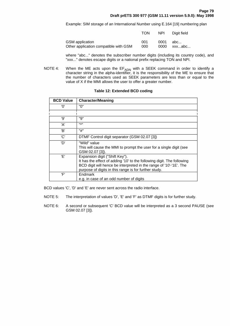
Page 79Draft prETS 300 977 (GSM 11.11 version 5.9.0): May 1998
Example: SIM storage of an International Number using E.164 [19] numbering plan
TON NPI Digit field
GSM application 001 0001 abc...Other application compatible with GSM 000 0000 xxx...abc...
where "abc..." denotes the subscriber number digits (including its country code), and"xxx..." denotes escape digits or a national prefix replacing TON and NPI.
NOTE 4: When the ME acts upon the EFADN with a SEEK command in order to identify acharacter string in the alpha-identifier, it is the responsibility of the ME to ensure thatthe number of characters used as SEEK parameters are less than or equal to thevalue of X if the MMI allows the user to offer a greater number.
Table 12: Extended BCD coding
BCD Value Character/Meaning
'0' "0"
'9' "9"
'A' "*"
'B' "#"
'C' DTMF Control digit separator (GSM 02.07 [3])
'D' "Wild" valueThis will cause the MMI to prompt the user for a single digit (seeGSM 02.07 [3]).
'E' Expansion digit ("Shift Key").It has the effect of adding '10' to the following digit. The followingBCD digit will hence be interpreted in the range of '10'-'1E'. Thepurpose of digits in this range is for further study.
'F' Endmarke.g. in case of an odd number of digits
BCD values 'C', 'D' and 'E' are never sent across the radio interface.
NOTE 5: The interpretation of values 'D', 'E' and 'F' as DTMF digits is for further study.
NOTE 6: A second or subsequent 'C' BCD value will be interpreted as a 3 second PAUSE (seeGSM 02.07 [3]).

Page 80Draft prETS 300 977 (GSM 11.11 version 5.9.0): May 1998
10.4.2 EFFDN (Fixed dialling numbers)
This EF contains Fixed Dialling Numbers (FDN) and/or Supplementary Service Control strings (SSC). Inaddition it contains identifiers of associated network/bearer capabilities and identifiers of extensionrecords. It may also contain an associated alpha-tagging.
Identifier: '6F3B' Structure: linear fixed OptionalRecord length: X+14 bytes Update activity: low
Access Conditions:READ CHV1UPDATE CHV2INVALIDATE ADMREHABILITATE ADM
Bytes Description M/O Length1 to X Alpha Identifier O X bytesX+1 Length of BCD number/SSC contents M 1 byteX+2 TON and NPI M 1 byte
X+3 to X+12 Dialling Number/SSC String M 10 bytesX+13 Capability/Configuration Identifier M 1 byteX+14 Extension2 Record Identifier M 1 byte
For contents and coding of all data items see the respective data items of the EFADN (subclause 10.4.1),with the exception that extension records are stored in the EFEXT2.
NOTE: The value of X (the number of bytes in the alpha-identifier) may be different to thelength denoted X in EFADN.
10.4.3 EFSMS (Short messages)
This EF contains information in accordance with GSM 03.40 [13] comprising short messages (andassociated parameters) which have either been received by the MS from the network, or are to be usedas an MS originated message.
Identifier: '6F3C' Structure: linear fixed OptionalRecord length: 176 bytes Update activity: low
Access Conditions:READ CHV1UPDATE CHV1INVALIDATE ADMREHABILITATE ADM
Bytes Description M/O Length1 Status M 1 byte
2 to 176 Remainder M 175 bytes

Page 81Draft prETS 300 977 (GSM 11.11 version 5.9.0): May 1998
- StatusContents: Status byte of the record which can be used as a pattern in the SEEK command. If
$(SMSR)$ is supported, then for MS originating messages sent to the network, the statusshall be updated when the MS receives a status report, or sends a successful SMSCommand relating to the status report.
Coding if $(SMSR)$ is supported:��������������������������E��E��E��E��E��E��E��E���������������������������� � � � � [ [ � IUHH VSDFH� � � � � [ [ � XVHG VSDFH� � � � � � � � PHVVDJH UHFHLYHG E\ 06 IURP QHWZRUN�� � � � � PHVVDJH UHDG� � � � � � � � PHVVDJH UHFHLYHG E\ 06 IURP QHWZRUN�� � � � � PHVVDJH WR EH UHDG� � � � � � � � 06 RULJLQDWLQJ PHVVDJH� PHVVDJH WR EH� � � � � VHQW���������������������� 5)8 �VHH VXEFODXVH ����
��������������������������E��E��E��E��E��E��E��E���������������������������� � � [ [ � � � 06 RULJLQDWLQJ PHVVDJH�� � � PHVVDJH VHQW WR WKH QHWZRUN�� � � � � � � � VWDWXV UHSRUW QRW UHTXHVWHG�� � � � � � � � VWDWXV UHSRUW UHTXHVWHG EXW QRW� � � �\HW� UHFHLYHG�� � � � � � � � VWDWXV UHSRUW UHTXHVWHG� UHFHLYHG� � � EXW QRW VWRUHG LQ ()�6065�� � � � � � � � VWDWXV UHSRUW UHTXHVWHG� UHFHLYHG� � � DQG VWRUHG LQ ()�6065����������������������� 5)8 �VHH VXEFODXVH ����
Coding if $(SMSR)$ is not supported:¸¶¶¾¶¶¾¶¶¾¶¶¾¶¶¾¶¶¾¶¶¾¶¶¹·E�·E�·E�·E�·E�·E�·E�·E�·º¾¶¿¾¶¿¾¶¿¾¶¿¾¶¿¾¶¿¾¶¿¾¶»· · · · · � � � IUHH VSDFH· · · · · [ [ � XVHG VSDFH· · · · · � � � PHVVDJH UHFHLYHG E\ 06 IURP QHWZRUN�· · · · · PHVVDJH UHDG· · · · · � � � PHVVDJH UHFHLYHG E\ 06 IURP QHWZRUN�· · · · · PHVVDJH WR EH UHDG· · · · · � � � 06 RULJLQDWLQJ PHVVDJH�· · · · · PHVVDJH VHQW WR WKH QHWZRUN· · · · · � � � 06 RULJLQDWLQJ PHVVDJH� PHVVDJH WR EH VHQW· · · · ·º¶¶¿¶¶¿¶¶¿¶¶¿¶¶¶¶¶¶¶¶¶ 5)8 �VHH VXEFODXVH ����
- RemainderContents: This data item commences with the TS-Service-Centre-Address as specified in
GSM 04.11 [16]. The bytes immediately following the TS-Service-Centre-Address contain anappropriate short message TPDU as specified in GSM 03.40 [13], with identical coding andordering of parameters.
Coding: according to GSM 03.40 [13] and GSM 04.11 [16]. Any TP-message reference contained inan MS originated message stored in the SIM, shall have a value as follows:
Value of the TP-message-referencemessage to be sent: 'FF'message sent to the network: the value of TP-Message-Reference used in the
message sent to the network.
Any bytes in the record following the TPDU shall be filled with 'FF'.
It is possible for a TS-Service-Centre-Address of maximum permitted length, e.g. containingmore than 18 address digits, to be associated with a maximum length TPDU such that theircombined length is 176 bytes. In this case the ME shall store in the SIM theTS-Service-Centre-Address and the TPDU in bytes 2-176 without modification, except for thelast byte of the TPDU, which shall not be stored.

Page 82Draft prETS 300 977 (GSM 11.11 version 5.9.0): May 1998
10.4.4 EFCCP (Capability configuration parameters)
This EF contains parameters of required network and bearer capabilities and ME configurationsassociated with a call established using an abbreviated dialling number, a fixed dialling number, anMSISDN, a last number dialled, a service dialling number or a barred dialling number.
Identifier: '6F3D' Structure: linear fixed OptionalRecord length: 14 bytes Update activity: low
Access Conditions:READ CHV1UPDATE CHV1INVALIDATE ADMREHABILITATE ADM
Bytes Description M/O Length1 to 10 Bearer capability information element M 10 bytes11 to 14 Bytes reserved - see below M 4 bytes
- Bearer capability information elementContents and Coding: see GSM 04.08 [15].
- Bytes 11-14 shall be set to 'FF' and shall not be interpreted by the ME.
10.4.5 EFMSISDN (MSISDN)
This EF contains MSISDN(s) related to the subscriber. In addition it contains identifiers of associatednetwork/bearer capabilities and identifiers of extension records. It may also contain an associatedalpha-tagging.
Identifier: '6F40' Structure: linear fixed OptionalRecord length: X+14 bytes Update activity: low
Access Conditions:READ CHV1UPDATE CHV1INVALIDATE ADMREHABILITATE ADM
Bytes Description M/O Length1 to X Alpha Identifier O X bytesX+1 Length of BCD number/SSC contents M 1 byteX+2 TON and NPI M 1 byte
X+3 to X+12 Dialling Number/SSC String M 10 bytesX+13 Capability/Configuration Identifier M 1 byteX+14 Extension1 Record Identifier M 1 byte
For contents and coding of all data items see the respective data items of EFADN.
NOTE 1: If the SIM stores more than one MSISDN number and the ME displays the MSISDNnumber(s) within the initialization procedure then the one stored in the first record shallbe displayed with priority.
NOTE 2: The value of X (the number of bytes in the alpha-identifier) may be different to thelength denoted X in EFADN.
10.4.6 EFSMSP (Short message service parameters)
This EF contains values for Short Message Service header Parameters (SMSP), which can be used bythe ME for user assistance in preparation of mobile originated short messages. For example, a servicecentre address will often be common to many short messages sent by the subscriber.

Page 83Draft prETS 300 977 (GSM 11.11 version 5.9.0): May 1998
The EF consists of one or more records, with each record able to hold a set of SMS parameters. The first(or only) record in the EF shall be used as a default set of parameters, if no other record is selected.
To distinguish between records, an alpha-identifier may be included within each record, coded on Y bytes.
The SMS parameters stored within a record may be present or absent independently. When a shortmessage is to be sent from the MS, the parameter in the SIM record, if present, shall be used when avalue is not supplied by the user.
Identifier: '6F42' Structure: linear fixed OptionalRecord length: 28+Y bytes Update activity: low
Access Conditions:READ CHV1UPDATE CHV1INVALIDATE ADMREHABILITATE ADM
Bytes Description M/O
Length
1 to Y Alpha-Identifier O Y bytesY+1 Parameter Indicators M 1 byte
Y+2 to Y+13 TP-Destination Address M 12 bytesY+14 to Y+25 TS-Service Centre Address M 12 bytes
Y+26 TP-Protocol Identifier M 1 byteY+27 TP-Data Coding Scheme M 1 byteY+28 TP-Validity Period M 1 byte
Storage is allocated for all of the possible SMS parameters, regardless of whether they are present orabsent. Any bytes unused, due to parameters not requiring all of the bytes, or due to absent parameters,shall be set to 'FF'.
- Alpha-IdentifierContents: Alpha Tag of the associated SMS-parameter.Coding: see 10.4.1 (EFADN).
NOTE: The value of Y may be zero, i.e. the alpha-identifier facility is not used. By using thecommand GET RESPONSE the ME can determine the value of Y.
- Parameter IndicatorsContents: Each of the default SMS parameters which can be stored in the remainder of the record
are marked absent or present by individual bits within this byte.Coding: Allocation of bits:
Bit number Parameter indicated 1 TP-Destination Address 2 TS-Service Centre Address 3 TP-Protocol Identifier 4 TP-Data Coding Scheme 5 TP-Validity Period 6 reserved, set to 1 7 reserved, set to 1 8 reserved, set to 1
Bit value Meaning 0 Parameter present 1 Parameter absent
- TP-Destination AddressContents and Coding: As defined for SM-TL address fields in GSM 03.40 [13].
- TP-Service Centre AddressContents and Coding: As defined for RP-Destination address Centre Address in GSM 04.11 [16].
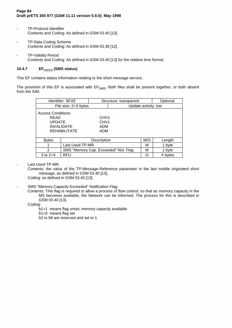
Page 84Draft prETS 300 977 (GSM 11.11 version 5.9.0): May 1998
- TP-Protocol IdentifierContents and Coding: As defined in GSM 03.40 [13].
- TP-Data Coding SchemeContents and Coding: As defined in GSM 03.38 [12].
- TP-Validity PeriodContents and Coding: As defined in GSM 03.40 [13] for the relative time format.
10.4.7 EFSMSS (SMS status)
This EF contains status information relating to the short message service.
The provision of this EF is associated with EFSMS. Both files shall be present together, or both absentfrom the SIM.
Identifier: '6F43' Structure: transparent OptionalFile size: 2+X bytes Update activity: low
Access Conditions:READ CHV1UPDATE CHV1INVALIDATE ADMREHABILITATE ADM
Bytes Description M/O Length1 Last Used TP-MR M 1 byte2 SMS "Memory Cap. Exceeded" Not. Flag M 1 byte
3 to 2+X RFU O X bytes
- Last Used TP-MR.Contents: the value of the TP-Message-Reference parameter in the last mobile originated short
message, as defined in GSM 03.40 [13].Coding: as defined in GSM 03.40 [13].
- SMS "Memory Capacity Exceeded" Notification Flag.Contents: This flag is required to allow a process of flow control, so that as memory capacity in the
MS becomes available, the Network can be informed. The process for this is described inGSM 03.40 [13].
Coding:b1=1 means flag unset; memory capacity availableb1=0 means flag setb2 to b8 are reserved and set to 1.

Page 85Draft prETS 300 977 (GSM 11.11 version 5.9.0): May 1998
10.4.8 EFLND (Last number dialled)
This EF contains the last numbers dialled (LND) and/or the respective supplementary service controlstrings (SSC). In addition it contains identifiers of associated network/bearer capabilities and identifiers ofextension records. It may also contain associated alpha-tagging.
Identifier: '6F44' Structure: cyclic OptionalRecord length: X+14 bytes Update activity: low
Access Conditions:READ CHV1UPDATE CHV1INCREASE NEVERINVALIDATE ADMREHABILITATE ADM
Bytes Description M/O Length1 to X Alpha Identifier O X bytesX+1 Length of BCD number/SSC contents M 1 byteX+2 TON and NPI M 1 byte
X+3 to X+12 Dialling Number/SSC String M 10 bytesX+13 Capability/Configuration Identifier M 1 byteX+14 Extension1 Record Identifier M 1 byte
Contents and coding: see EFADN.
The value of X in EFLND may be different to both the value of X in EFADN and of X in EFFDN.
If the value of X in EFLND is longer than the length of the α-tag of the number to be stored, then the MEshall pad the α-tag with 'FF'. If the value of X in EFLND is shorter than the length of the α-tag of thenumber to be stored, then the ME shall cut off excessive bytes.
10.4.9 EFSDN (Service Dialling Numbers)
This EF contains special service numbers (SDN) and/or the respective supplementary service controlstrings (SSC). In addition it contains identifiers of associated network/bearer capabilities and identifiers ofextension records. It may also contain associated alpha-tagging.
Identifier: '6F49' Structure: linear fixed OptionalRecord length: X+14 bytes Update activity: low
Access Conditions:READ CHV1UPDATE ADMINVALIDATE ADMREHABILITATE ADM
Bytes Description M/O Length1-X Alpha identifier O X bytesX+1 Length of BCD number/SSC contents M 1 bytesX+2 TON and NPI M 1 byte
X+3-X+12 Dialling Number/SSC String M 10 bytesX+13 Capability/Configuration Identifier M 1 byteX+14 Extension3 Record Identifier M 1 byte
For contents and coding of all data items see the respective data items of the EFADN (subclause 10.4.1),with the exception that extension records are stored in the EFEXT3.
NOTE: The value of X (the number of bytes in the alpha-identifier) may be different to thelength denoted X in EFADN.

Page 86Draft prETS 300 977 (GSM 11.11 version 5.9.0): May 1998
10.4.10 EFEXT1 (Extension1)
This EF contains extension data of an ADN/SSC, an MSISDN, or an LND. Extension data is caused by:
- an ADN/SSC (MSISDN, LND) which is greater than the 20 digit capacity of the ADN/SSC(MSISDN, LND) Elementary File or, if $(DNE)$ is supported, where common digits arerequired to follow an ADN/SSC string of less than 20 digits. The remainder is stored in thisEF as a record, which is identified by a specified identification byte inside the ADN/SSC(MSISDN, LND) Elementary File. The EXT1 record in this case is specified as additionaldata;
- an associated called party subaddress. The EXT1 record in this case is specified assubaddress data.
Identifier: '6F4A' Structure: linear fixed OptionalRecord length: 13 bytes Update activity: low
Access Conditions:READ CHV1UPDATE CHV1INVALIDATE ADMREHABILITATE ADM
Bytes Description M/O Length1 Record type M 1 byte
2 to 12 Extension data M 11 bytes13 Identifier M 1 byte
- Record typeContents: type of the recordCoding:
¸¶¶¾¶¶¾¶¶¾¶¶¾¶¶¾¶¶¾¶¶¾¶¶¹·E�·E�·E�·E�·E�·E�·E�·E�·º¾¶¿¾¶¿¾¶¿¾¶¿¾¶¿¾¶¿¾¶¿¾¶»· · · · · · · º¶¶ &DOOHG 3DUW\ 6XEDGGUHVV· · · · · · º¶¶¶¶¶ $GGLWLRQDO GDWDº¶¶¿¶¶¿¶¶¿¶¶¿¶¶¿¶¶¶¶¶¶¶¶ 5)8
b3-b8 are reserved and set to 0;a bit set to 1 identifies the type of record;only one type can be set;'00' indicates the type "unknown".
The following example of coding means that the type of extension data is "additional data":¸¶¶¾¶¶¾¶¶¾¶¶¾¶¶¾¶¶¾¶¶¾¶¶¹·E�·E�·E�·E�·E�·E�·E�·E�·º¾¶¿¾¶¿¾¶¿¾¶¿¾¶¿¾¶¿¾¶¿¾¶»� � � � � � � �
- Extension dataContents: Additional data or Called Party Subaddress depending on record type.Coding:
Case 1, Extension1 record is additional data:The first byte of the extension data gives the number of bytes of the remainder ofADN/SSC (respectively MSISDN, LND). The coding of remaining bytes is BCD,according to the coding of ADN/SSC (MSISDN, LND). Unused nibbles at the end haveto be set to 'F'. It is possible if the number of additional digits exceeds the capacity ofthe additional record to chain another record inside the EXT1 Elementary File by theidentifier in byte 13.
Case 2, Extension1 record is Called Party Subaddress:The subaddress data contains information as defined for this purpose inGSM 04.08 [15]. All information defined in GSM 04.08, except the information elementidentifier, shall be stored in the SIM. The length of this subaddress data can be up to22 bytes. In those cases where two extension records are needed, these records arechained by the identifier field. The extension record containing the first part of thecalled party subaddress points to the record which contains the second part of thesubaddress.

Page 87Draft prETS 300 977 (GSM 11.11 version 5.9.0): May 1998
- IdentifierContents: identifier of the next extension record to enable storage of information longer than
11 bytes.Coding: record number of next record. 'FF' identifies the end of the chain.
Example of a chain of extension records being associated to an ADN/SSC. The extension1 recordidentifier (Byte 14+X) of ADN/SSC is set to 3.
No of Record Type Extension Data Next Record. . . .. . . .
Record 3 '02' xx ........xx '06' !¶¶¶¶¶¶¶¶¶¶¹
Record 4 'xx' xx ........xx 'xx' ·
Record 5 '01' xx ........xx 'FF' �¶¶¶¶¶¶¶¹ ·
Record 6 '01' xx ........xx '05' �¶¶¶¶¶¶¶¿¶¶»
. . . .
. . . .
In this example ADN/SSC is associated to additional data (record 3) and a called party subaddresswhose length is more than 11 bytes (records 6 and 5).
10.4.11 EFEXT2 (Extension2)
This EF contains extension data of an FDN/SSC (see EXT2 in 10.4.2).
Identifier: '6F4B' Structure: linear fixed OptionalRecord length: 13 bytes Update activity: low
Access Conditions:READ CHV1UPDATE CHV2INVALIDATE ADMREHABILITATE ADM
Bytes Description M/O Length1 Record type M 1 byte
2 to 12 Extension data M 11 bytes13 Identifier M 1 byte
For contents and coding see subclause 10.4.10 EFEXT1.
10.4.12 EFEXT3 (Extension3)
This EF contains extension data of an SDN (see EXT3 in 10.4.9).
Identifier: '6F4C' Structure: linear fixed OptionalRecord length: 13 bytes Update activity: low
Access Conditions:READ CHV1UPDATE ADMINVALIDATE ADMREHABILITATE ADM
Bytes Description M/O Length1 Record type M 1 byte
2 to 12 Extension data M 11 bytes13 Identifier M 1 byte
For contents and coding see subclause 10.4.10 EFEXT1 .

Page 88Draft prETS 300 977 (GSM 11.11 version 5.9.0): May 1998
10.4.13 EFBDN (Barred Dialling Numbers)
This EF contains Barred Dialling Numbers (BDN) and/or Supplementary Service Control strings (SSC). Inaddition it contains identifiers of associated network/bearer capabilities and identifiers of extensionrecords. It may also contain an associated alpha-tagging.
Identifier: '6F4D' Structure: linear fixed OptionalRecord length: X+15 bytes Update activity: low
Access Conditions:READ CHV1UPDATE CHV2INVALIDATE CHV2REHABILITATE CHV2
Bytes Description M/O Length1 to X Alpha Identifier O X bytesX+1 Length of BCD number/SSC contents M 1 byteX+2 TON and NPI M 1 byte
X+3 to X+12 Dialling Number/SSC String M 10 bytesX+13 Capability/Configuration Identifier M 1 byteX+14 Extension4 Record Identifier M 1 byteX+15 Comparison Method Information M 1 byte
For contents and coding of all data items, except for the Comparison Method Information, see therespective data items of the EFADN (subclause 10.4.1), with the exception that extension records arestored in the EFEXT4.
NOTE: The value of X (the number of bytes in the alpha-identifier) may be different to thelength denoted X in EFADN.
- Comparison Method InformationContents: this byte describes the comparison method which is associated with that BDN. Its
interpretation is not specified but it shall be defined by the operators implementing the BDNfeature on their SIMs.
Coding: binary; values from 0 to 255 are allowed.
10.4.14 EFEXT4 (Extension4)
This EF contains extension data of an BDN/SSC (see EXT4 in 10.4.13).
Identifier: '6F4E' Structure: linear fixed OptionalRecord length: 13 bytes Update activity: low
Access Conditions:READ CHV1UPDATE CHV2INVALIDATE ADMREHABILITATE ADM
Bytes Description M/O Length1 Record type M 1 byte
2 to 12 Extension data M 11 bytes13 Identifier M 1 byte
For contents and coding see subclause 10.4.10 EFEXT1 .
10.4.15 EFSMSR (Short message status reports)
This subclause applies only if $(SMSR)$ is supported. This EF contains information in accordance withTS GSM 03.40 [13] comprising short message status reports which have been received by the MS fromthe network.

Page 89Draft prETS 300 977 (GSM 11.11 version 5.9.0): May 1998
Each record is used to store the status report of a short message in a record of EFSMS. The first byte ofeach record is the link between the status report and the corresponding short message in EFSMS.
Identifier: '6F47' Structure: linear fixed OptionalRecord length: 30 bytes Update activity: low
Access Conditions:READ CHV1UPDATE CHV1INVALIDATE ADMREHABILITATE ADM
Bytes Description M/O Length1 SMS record identifier M 1
2 - 30 SMS status report M 29 bytes
- SMS record identifierContents: This data item identifies the corresponding SMS record in EFSMS, e.g. if this byte is coded
‘05’ then this status report corresponds to the short message in record #5 of EFSMS.Coding: ‘00’ - empty record
‘01’ - ‘FF’ - record number of the corresponding SMS in EFSMS.- SMS status report
Contents: This data item contains the SMS-STATUS-REPORT TPDU as specified in TS GSM03.40 [13], with identical coding and ordering of parameters.
Coding: according to TS GSM 03.40 [13]. Any bytes in the record following the TPDU shall be filledwith 'FF'.
10.5 Files of GSM (figure 8)
This subclause contains a figure depicting the file structure of the SIM. DFGSM shall be selected using theidentifier '7F20'. If selection by this means fails, then DCS 1800 MEs shall, and optionally GSM MEs maythen select DFGSM with '7F21'.
NOTE 1: The selection of the GSM application using the identifier '7F21', if selection by meansof the identifier '7F20' fails, is to ensure backwards compatibility with those Phase 1SIMs which only support the DCS 1800 application using the Phase 1 directoryDFDCS1800 coded '7F21'.
NOTE 2: To ensure backwards compatibility with those Phase 1 DCS 1800 MEs which have nomeans to select DFGSM two options have been specified. These options are given inGSM 09.91 [17].
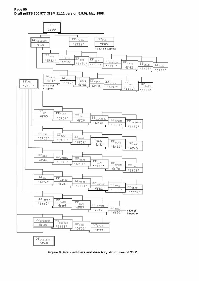
Page 90Draft prETS 300 977 (GSM 11.11 version 5.9.0): May 1998
DFTELECOM
'7F10'
EFICCID
'2FE2'
EFMSISDN
'6F3A' '6F3B'
EFADN EFFDN
MF
SMS
'3F00'
EF
EF EFCCP EFSMSP SMSS
EXT4
EF'6F3C' '6F3D' '6F40' '6F42' '6F43' '6F44'
'6F49''6F4A' '6F4B' '6F4C' '6F4D' '6F4E'
DFGSM
EF
EF EF EF EF EF EFBDNEXT3EXT2EXT1SDN
LND
'7F20'
'6F05''6F07'
'6F20''6F30'
'6F31' '6F37'
'6F38''6F39'
'6F3E''6F3F'
'6F41' '6F45'
EFEF
EFACMmaxEFHPLMN
EFPLMNsel
LPIMSI
Kc
EF EFEF
EFEF
EF
EFEF
EFEFEFEF
SSTACM
GID1GID2
PUCTCBMI
SPNCBMID
BCCHACC
FPLMNLOCI
EF EFEF
EFEF EF
ADPHASE
VGCSVGCSS
VBSVBSS
EF EFEF
EF
eMLPPAAeM
ECCCBMIR
DF DFDF DF
DF
IridiumGlobst
ICO ACeS
PCS1900
'6F46''6F48'
'6F74''6F78'
'6F7B''6F7E'
'6FAD''6FAE'
'6FB1''6FB2' '6FB3'
'6FB4'
'6FB5''6FB6'
'6FB7''6F50'
'5F30''5F31'
'5F32''5F33'
'5F40'
EFELP
'2F05'
If $(SMSR)$is supported
'6F47'
EFSMSR
If $(ELP)$ is supported
EF NIA
'6F51'If $(NIA)$ is supported
Figure 8: File identifiers and directory structures of GSM
Page 91Draft prETS 300 977 (GSM 11.11 version 5.9.0): May 1998
11 Application protocol
When involved in GSM administrative management operations, the SIM interfaces with appropriateterminal equipment. These operations are outside the scope of this standard.
When involved in GSM network operations the SIM interfaces with an ME with which messages areexchanged. A message can be a command or a response.
- A GSM command/response pair is a sequence consisting of a command and the associatedresponse.
- A GSM procedure consists of one or more GSM command/response pairs which are used toperform all or part of an application-oriented task. A procedure shall be considered as awhole, that is to say that the corresponding task is achieved if and only if the procedure iscompleted. The ME shall ensure that, when operated according to the manufacturer'smanual, any unspecified interruption of the sequence of command/response pairs whichrealize the procedure, leads to the abortion of the procedure itself.
- A GSM session of the SIM in the GSM application is the interval of time starting at thecompletion of the SIM initialization procedure and ending either with the start of the GSMsession termination procedure, or at the first instant the link between the SIM and the ME isinterrupted.
During the GSM network operation phase, the ME plays the role of the master and the SIM plays the roleof the slave.
Some procedures at the SIM/ME interface require MMI interactions. The descriptions hereafter do notintend to infer any specific implementation of the corresponding MMI. When MMI interaction is required, itis marked "MMI" in the list given below.
Some procedures are not clearly user dependent. They are directly caused by the interaction of the MSand the network. Such procedures are marked "NET" in the list given below.
Some procedures are automatically initiated by the ME. They are marked "ME" in the list given below.
The list of procedures at the SIM/ME interface in GSM network operation is as follows:
General Procedures:
- Reading an EF ME- Updating an EF ME- Increasing an EF ME
SIM management procedures:
- SIM initialization ME- GSM session termination ME- Emergency call codes request ME- Extended language preference request ME- Language preference request ME- Administrative information request ME- SIM service table request ME- SIM phase request ME
CHV related procedures:
- CHV verification MMI- CHV value substitution MMI- CHV disabling MMI- CHV enabling MMI- CHV unblocking MMI

Page 92Draft prETS 300 977 (GSM 11.11 version 5.9.0): May 1998
GSM security related procedures:
- GSM algorithms computation NET- IMSI request NET- Access control information request NET- HPLMN search period request NET- Location Information NET- Cipher key NET- BCCH information NET- Forbidden PLMN information NET
Subscription related procedures:
- Dialling Numbers (ADN, FDN, MSISDN, LND, SDN, BDN) MMI/ME- Short messages (SMS) MMI- Advice of Charge (AoC) MMI- Capability Configuration Parameters (CCP) MMI- PLMN Selector MMI- Cell Broadcast Message Identifier (CBMI) MMI- Group Identifier Level 1 (GID1) MMI/ME- Group Identifier Level 2 (GID2) MMI/ME- Service Provider Name (SPN) ME- Voice Group Call Service (VGCS) MMI/ME- Voice Broadcast Service (VBS) MMI/ME- Enhanced Multi Level Pre-emption and Priority (eMLPP) MMI/ME- Depersonalisation Control Keys ME- Short message status reports (SMSR) (if $(SMSR)$ is supported) MMI- Network's indication of alerting (if $(NIA)$ is supported) ME
SIM Application Toolkit related procedures:
- Data Download via SMS-CB (CBMID) NET- Data Download via SMS-PP NET- Menu selection MMI- Call Control MMI/ME/NET- Proactive SIM MMI/ME/NET- Mobile Originated Short Message control by SIM MMI/ME/NET
(if $(MOSMcontrol)$ is supported)
The procedures listed in subclause 11.2 are basically required for execution of the procedures insubclauses 11.3, 11.4 and 11.5. The procedures listed in subclauses 11.3 and 11.4 are mandatory (seeGSM 02.17 [6]). The procedures listed in 11.5 are only executable if the associated services, which areoptional, are provided in the SIM. However, if the procedures are implemented, it shall be in accordancewith subclause 11.5.
If a procedure is related to a specific service indicated in the SIM Service Table, it shall only be executed ifthe corresponding bits denote this service as "allocated and activated" (see subclause 10.3.7). In all othercases this procedure shall not start.
11.1 General procedures
11.1.1 Reading an EF
The ME selects the EF and sends a READ command. This contains the location of the data to be read. Ifthe access condition for READ is fulfilled, the SIM sends the requested data contained in the EF to theME. If the access condition is not fulfilled, no data will be sent and an error code will be returned.
11.1.2 Updating an EF
The ME selects the EF and sends an UPDATE command. This contains the location of the data to beupdated and the new data to be stored. If the access condition for UPDATE is fulfilled, the SIM updatesthe selected EF by replacing the existing data in the EF with that contained in the command. If the access

Page 93Draft prETS 300 977 (GSM 11.11 version 5.9.0): May 1998
condition is not fulfilled, the data existing in the EF will be unchanged, the new data will not be stored, andan error code will be returned.
11.1.3 Increasing an EF
The ME selects the EF and sends an INCREASE command. This contains the value which has to beadded to the contents of the last updated/increased record. If the access condition for INCREASE isfulfilled, the SIM increases the existing value of the EF by the data contained in the command, and storesthe result. If the access condition is not fulfilled, the data existing in the EF will be unchanged and an errorcode will be returned.
NOTE: The identification of the data within an EF to be acted upon by the above procedures isspecified within the command. For the procedures in subclauses 11.1.1 and 11.1.2 thisdata may have been previously identified using a SEEK command, e.g. searching foran alphanumeric pattern.
11.2 SIM management procedures
Phase 2 MEs shall support all SIMs which comply with the mandatory requirements of Phase 1, even ifthese SIMs do not comply with all the mandatory requirements of Phase 2. Furthermore, Phase 2 MEsshall take care of potential incompatibilities with Phase 1 SIMs which could arise through use ofinappropriate commands or misinterpretation of response data. Particular note should be taken of makinga false interpretation of RFU bytes in a Phase 1 SIM having contradictory meaning in Phase 2; e.g.indication of EF invalidation state.
11.2.1 SIM initialization
This subclause contains some references to EFELP, the extended language preference. These referencesare normative only if $(ELP$) is supported..
After SIM activation (see subclause 4.3.2), the ME selects the Dedicated File DFGSM and optionallyattempts to select EFECC. If EFECC is available, the ME requests the emergency call codes.
The ME requests the Extended Language Preference. The ME only requests the Language Preference(EFLP) if at least one of the following conditions holds:
- EFELP is not available;- EFELP does not contain an entry corresponding to a language specified in ISO 639[30];- the ME does not support any of the languages in EFELP.
If both EFs are not available or none of the languages in the EFs is supported then the ME selects adefault language. It then runs the CHV1 verification procedure.
If the CHV1 verification procedure is performed successfully, the ME then runs the SIM Phase requestprocedure.
For a SIM requiring PROFILE DOWNLOAD, then the ME shall perform the PROFILE DOWNLOADprocedure in accordance with GSM 11.14 [27]. When BDN is enabled on a SIM, the PROFILEDOWNLOAD procedure is used to indicate to the SIM whether the ME supports the "Call Control by SIM"facility. If so, then the SIM is able to allow the REHABILITATE command to rehabilitate EFIMSI andEFLOCI.
If the ME detects a SIM of Phase 1, it shall omit the following procedures relating to FDN and continuewith the Administrative Information request. The ME may omit procedures not defined in Phase 1 such asHPLMN Search Period request.
For a SIM of Phase 2 or greater, GSM operation shall only start if one of the two following conditions isfulfilled:
- if EFIMSI and EFLOCI are not invalidated, the GSM operation shall start immediately;
- if EFIMSI and EFLOCI are invalidated, the ME rehabilitates these two EFs.

Page 94Draft prETS 300 977 (GSM 11.11 version 5.9.0): May 1998
MEs without FDN capability but with Call control by SIM facility shall not rehabilitate EFIMSI and/orEFLOCI if FDN is enabled in the SIM and therefore have no access to these EFs. GSM operation willtherefore be prohibited;
MEs without FDN capability and without Call control by SIM facility shall not rehabilitate EFIMSIand/or EFLOCI and therefore have no access to these EFs. GSM operation will therefore beprohibited.
It is these mechanisms which are used for control of services n°3 and n°31 by the use of SIMs forthese services which always invalidate these two EFs at least before the next command followingselection of either EF.
NOTE: When FDN and BDN are both enabled, and if the ME supports FDN but does notsupport the Call control by SIM facility, the rehabilitation of EFIMSI and EFLOCI will notbe successful because of a restriction mechanism of the REHABILITATE commandlinked to the BDN feature.
When EFIMSI and EFLOCI are successfully rehabilitated, if the FDN capability procedureindicates that:
i) FDN is allocated and activated in the SIM; and FDN is set "enabled", i.e. ADN "invalidated" ornot activated; and the ME supports FDN;
or ii) FDN is allocated and activated in the SIM; and FDN is set "disabled", i.e. ADN "notinvalidated";
or iii) FDN is not allocated or not activated;
then GSM operation shall start.
In all other cases GSM operation shall not start.
Afterwards, the ME runs the following procedures:
- Administrative Information request;- SIM Service Table request;- IMSI request;- Access Control request;- HPLMN Search Period request;- PLMN selector request;- Location Information request;- Cipher Key request;- BCCH information request;- Forbidden PLMN request;- CBMID request;- Depersonalisation Control Keys request- Network's indication of alerting request (if $(NIA)$ is supported)
If the SIM service table indicates that the proactive SIM service is active, then from this point onwards, theME, if it supports the proactive SIM service, shall send STATUS commands at least every 30s during idlemode as well as during calls, in order to enable the proactive SIM to respond with a command. The SIMmay send proactive commands (see GSM 11.14 [27]), including a command to change the intervalbetween STATUS commands from the ME, when in idle mode. In-call requirements for STATUS for SIMPresence Detection are unchanged by this command.
After the SIM initialization has been completed successfully, the MS is ready for a GSM session.
11.2.2 GSM session termination
NOTE 1: This procedure is not to be confused with the deactivation procedure insubclause 4.3.2.
The GSM session is terminated by the ME as follows:

Page 95Draft prETS 300 977 (GSM 11.11 version 5.9.0): May 1998
The ME runs all the procedures which are necessary to transfer the following subscriber relatedinformation to the SIM:
- Location Information update;- Cipher Key update;- BCCH information update;- Advice of Charge increase;- Forbidden PLMN update.
As soon as the SIM indicates that these procedures are completed, the ME/SIM link may be deactivated.
Finally, the ME deletes all these subscriber related information elements from its memory.
NOTE 2: If the ME has already updated any of the subscriber related information during theGSM Session, and the value has not changed until GSM session termination, the MEmay omit the respective update procedure.
11.2.3 Emergency Call Codes
Request: The ME performs the reading procedure with EFECC.
Update: The ME performs the updating procedure with EFECC.
NOTE: The update procedure is only applicable when access conditions of ADM for update isset to ALW, CHV1 or CHV2.
11.2.4 Language preference
Request: The ME performs the reading procedure with EFLP.
Update: The ME performs the updating procedure with EFLP.
11.2.5 Administrative information request;
The ME performs the reading procedure with EFAD.
11.2.6 SIM service table request
The ME performs the reading procedure with EFSST.
11.2.7 SIM phase request
The ME performs the reading procedure with EFPHASE.
11.2.8 SIM Presence Detection and Proactive Polling
As an additional mechanism, to ensure that the SIM has not been removed during a card session, the MEsends, at frequent intervals, a STATUS command during each call. A STATUS command shall be issuedwithin all 30 second periods of inactivity on the SIM-ME interface during a call. Inactivity in this case isdefined as starting at the end of the last communication or the last issued STATUS command. If noresponse data is received to this STATUS command, then the call shall be terminated as soon aspossible but at least within 5 seconds after the STATUS command has been sent. If the DF indicated inresponse to a STATUS command is not the same as that which was indicated in the previous response,or accessed by the previous command, then the call shall be terminated as soon as possible but at leastwithin 5 seconds after the response data has been received. This procedure shall be used in addition to amechanical or other device used to detect the removal of a SIM.
If the ME supports the proactive SIM service, and the SIM has this service activated in its Service Table,then during idle mode the ME shall send STATUS commands to the SIM at intervals no longer than theinterval negotiated with the SIM (see GSM 11.14 [27]).
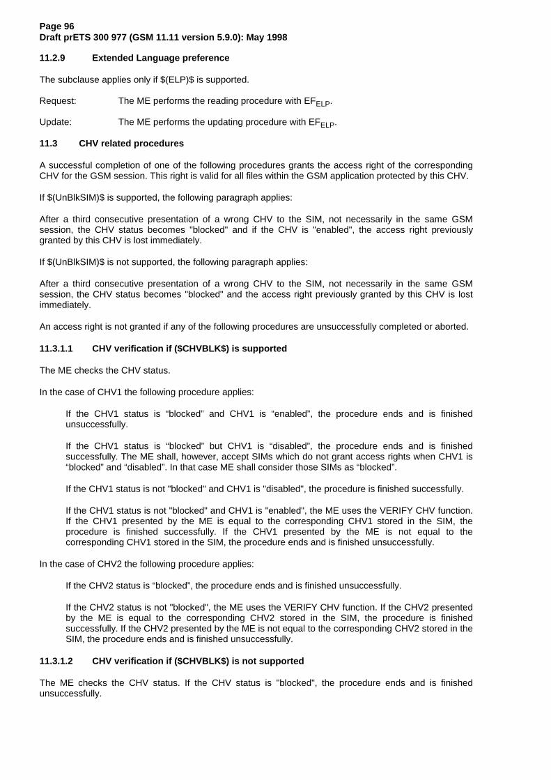
Page 96Draft prETS 300 977 (GSM 11.11 version 5.9.0): May 1998
11.2.9 Extended Language preference
The subclause applies only if $(ELP)$ is supported.
Request: The ME performs the reading procedure with EFELP.
Update: The ME performs the updating procedure with EFELP.
11.3 CHV related procedures
A successful completion of one of the following procedures grants the access right of the correspondingCHV for the GSM session. This right is valid for all files within the GSM application protected by this CHV.
If $(UnBlkSIM)$ is supported, the following paragraph applies:
After a third consecutive presentation of a wrong CHV to the SIM, not necessarily in the same GSMsession, the CHV status becomes "blocked" and if the CHV is "enabled", the access right previouslygranted by this CHV is lost immediately.
If $(UnBlkSIM)$ is not supported, the following paragraph applies:
After a third consecutive presentation of a wrong CHV to the SIM, not necessarily in the same GSMsession, the CHV status becomes "blocked" and the access right previously granted by this CHV is lostimmediately.
An access right is not granted if any of the following procedures are unsuccessfully completed or aborted.
11.3.1.1 CHV verification if ($CHVBLK$) is supported
The ME checks the CHV status.
In the case of CHV1 the following procedure applies:
If the CHV1 status is “blocked” and CHV1 is “enabled”, the procedure ends and is finishedunsuccessfully.
If the CHV1 status is “blocked” but CHV1 is “disabled”, the procedure ends and is finishedsuccessfully. The ME shall, however, accept SIMs which do not grant access rights when CHV1 is“blocked” and “disabled”. In that case ME shall consider those SIMs as “blocked”.
If the CHV1 status is not "blocked" and CHV1 is "disabled", the procedure is finished successfully.
If the CHV1 status is not "blocked" and CHV1 is "enabled", the ME uses the VERIFY CHV function.If the CHV1 presented by the ME is equal to the corresponding CHV1 stored in the SIM, theprocedure is finished successfully. If the CHV1 presented by the ME is not equal to thecorresponding CHV1 stored in the SIM, the procedure ends and is finished unsuccessfully.
In the case of CHV2 the following procedure applies:
If the CHV2 status is “blocked”, the procedure ends and is finished unsuccessfully.
If the CHV2 status is not "blocked", the ME uses the VERIFY CHV function. If the CHV2 presentedby the ME is equal to the corresponding CHV2 stored in the SIM, the procedure is finishedsuccessfully. If the CHV2 presented by the ME is not equal to the corresponding CHV2 stored in theSIM, the procedure ends and is finished unsuccessfully.
11.3.1.2 CHV verification if ($CHVBLK$) is not supported
The ME checks the CHV status. If the CHV status is "blocked", the procedure ends and is finishedunsuccessfully.

Page 97Draft prETS 300 977 (GSM 11.11 version 5.9.0): May 1998
If the CHV status is not "blocked", the ME reads the CHV enabled/disabled indicator. If this is "disabled",the procedure is finished successfully.
If the CHV status is not "blocked" and the enabled/disabled indicator is set "enabled", the ME uses theVERIFY CHV function. If the CHV presented by the ME is equal to the corresponding CHV stored in theSIM, the procedure is finished successfully. If the CHV presented by the ME is not equal to thecorresponding CHV stored in the SIM, the procedure ends and is finished unsuccessfully.
11.3.2 CHV value substitution
The ME checks the CHV status. If the CHV status is "blocked" or "disabled", the procedure ends and isfinished unsuccessfully.
If the CHV status is not "blocked" and the enabled/disabled indicator is set "enabled", the ME uses theCHANGE CHV function. If the old CHV presented by the ME is equal to the corresponding CHV stored inthe SIM, the new CHV presented by the ME is stored in the SIM and the procedure is finishedsuccessfully.
If the old CHV and the CHV in memory are not identical, the procedure ends and is finishedunsuccessfully.
11.3.3 CHV disabling
Requirement: Service n°1 "allocated and activated".
The ME checks the CHV1 status. If the CHV1 status is "blocked", the procedure ends and is finishedunsuccessfully.
If the CHV1 status is not "blocked", the ME reads the CHV1 enabled/disabled indicator. If this is set"disabled", the procedure ends and is finished unsuccessfully.
If the CHV1 status is not "blocked" and the enabled/disabled indicator is set "enabled", the ME uses theDISABLE CHV function. If the CHV1 presented by the ME is equal to the CHV1 stored in the SIM, thestatus of CHV1 is set "disabled" and the procedure is finished successfully. If the CHV1 presented by theME is not equal to the CHV1 stored in the SIM, the procedure ends and is finished unsuccessfully.
11.3.4 CHV enabling
The ME checks the CHV1 status. If the CHV1 status is "blocked", the procedure ends and is finishedunsuccessfully.
If the CHV1 status is not "blocked", the ME reads the CHV1 enabled/disabled indicator. If this is set"enabled", the procedure ends and is finished unsuccessfully.
If the CHV1 status is not "blocked" and the enabled/disabled indicator is set "disabled", the ME uses theENABLE CHV function. If the CHV1 presented by the ME is equal to the CHV1 stored in the SIM, thestatus of CHV1 is set "enabled" and the procedure is finished successfully. If the CHV presented by theME is not equal to the CHV1 stored in the SIM, the procedure ends and is finished unsuccessfully.
11.3.5 CHV unblocking
The execution of the CHV unblocking procedure is independent of the corresponding CHV status, i.e.being blocked or not.
The ME checks the UNBLOCK CHV status. If the UNBLOCK CHV status is "blocked", the procedure endsand is finished unsuccessfully.
If the UNBLOCK CHV status is not "blocked", the ME uses the UNBLOCK CHV function. If the UNBLOCKCHV presented by the ME is equal to the corresponding UNBLOCK CHV stored in the SIM, the relevantCHV status becomes "unblocked" and the procedure is finished successfully. If the UNBLOCK CHVpresented by the ME is not equal to the corresponding UNBLOCK CHV stored in the SIM, the procedureends and is finished unsuccessfully.

Page 98Draft prETS 300 977 (GSM 11.11 version 5.9.0): May 1998
11.4 GSM security related procedures
11.4.1 GSM algorithms computation
The ME selects DFGSM and uses the RUN GSM ALGORITHM function (see 8.16). The responseSRES-Kc is sent to the ME when requested by a subsequent GET RESPONSE command.
11.4.2 IMSI request
The ME performs the reading procedure with EFIMSI.
11.4.3 Access control request
The ME performs the reading procedure with EFACC.
11.4.4 HPLMN search period request
The ME performs the reading procedure with EFHPLMN.
11.4.5 Location information
Request: The ME performs the reading procedure with EFLOCI.
Update: The ME performs the updating procedure with EFLOCI.
11.4.6 Cipher key
Request: The ME performs the reading procedure with EFKc.
Update: The ME performs the updating procedure with EFKc.
11.4.7 BCCH information
Request: The ME performs the reading procedure with EFBCCH.
Update: The ME performs the updating procedure with EFBCCH.
11.4.8 Forbidden PLMN
Request: The ME performs the reading procedure with EFPLMN.
Update: The ME performs the updating procedure with EFPLMN.
11.5 Subscription related procedures
11.5.1 Dialling numbers
The following procedures may not only be applied to EFADN and its associated extension files EFCCP andEFEXT1 as described in the procedures below, but also to EFFDN, EFMSISDN, EFLND, EFBDN and EFSDNand their associated extension files. If these files are not allocated and activated, as denoted in the SIMservice table, the current procedure shall be aborted and the appropriate EFs shall remain unchanged.
As an example, the following procedures are described as applied to ADN.
Requirement: Service n°2 "allocated and activated"(Service n°3 for FDN, Service n°9 for MSISDN, Service n°13 for LND, Service n°18 for SDN), Service n°31 for BDN)

Page 99Draft prETS 300 977 (GSM 11.11 version 5.9.0): May 1998
Update: The ME analyses and assembles the information to be stored as follows (the byteidentifiers used below correspond to those in the description of the EFs insubclauses 10.4.1, 10.4.4 and 10.4.10):
i) The ME identifies the Alpha-tagging, Capability/Configuration Identifier and Extension1 RecordIdentifier.
ii) The dialling number/SSC string shall be analysed and allocated to the bytes of the EF as follows:
- if a "+" is found, the TON identifier is set to "International";
- if 20 or less "digits" remain, they shall form the dialling number/SSC string;
- if more than 20 "digits" remain, the procedure shall be as follows:
Requirement:Service n°10 "allocated and activated"(Service n°10 applies also for MSISDN and LND;Service n°11 for FDN;Service n°19 for SDN;Service n°32 for BDN.)
The ME seeks for a free record in EFEXT1. If an Extension1 record is not marked as "free",the ME runs the Purge procedure. If an Extension1 record is still unavailable, the procedureis aborted.
The first 20 "digits" are stored in the dialling number/SSC string. The value of the length ofBCD number/SSC contents is set to the maximum value, which is 11. The Extension1 recordidentifier is coded with the associated record number in the EFEXT1. The remaining digits arestored in the selected Extension1 record where the type of the record is set to "additionaldata". The first byte of the Extension1 record is set with the number of bytes of the remainingadditional data. The number of bytes containing digit information is the sum of the length ofBCD number/SSC contents of EFADN and byte 2 of all associated chained Extension1records containing additional data (see subclauses 10.4.1 and 10.4.10).
iii) If a called party subaddress is associated to the ADN/SSC the procedure shall proceed as follows:
Requirement:Service n°10 "allocated and activated"(Service n°10 applies also for MSISDN and LND;Service n°11 for FDN;Service n°19 for SDN;Service n°32 for BDN.)
If the length of the called party subaddress is less than or equal to 11 bytes (seeGSM 04.08 [15] for coding):
The ME seeks for a free record in EFEXT1. If an Extension1 record is not marked as "free",the ME runs the Purge procedure. If an Extension1 record is still unavailable, the procedureis aborted.
The ME stores the called party subaddress in the Extension1 record, and sets the Extension1record type to "called party subaddress".
If the length of the called party subaddress is greater than 11 bytes (see GSM 04.08 [15] forcoding):
The ME seeks for two free records in EFEXT1. If no such two records are found, the ME runsthe Purge procedure. If two Extension1 records are still unavailable, the procedure isaborted.
The ME stores the called party subaddress in the two Extension1 records. The identifier fieldin the Extension1 record containing the first part of the subaddress data is coded with the

Page 100Draft prETS 300 977 (GSM 11.11 version 5.9.0): May 1998
associated EFEXT1 record number containing the second part of the subaddress data. BothExtension1 record types are set to "called party subaddress".
Once i), ii), and iii) have been considered the ME performs the updating procedure with EFADN. If the SIMhas no available empty space to store the received ADN/SSC, or if the procedure has been aborted, theME advises the user.
NOTE 1: For reasons of memory efficiency the ME is allowed to analyse all Extension1 recordsto recognize if the additional or subaddress data to be stored is already existing inEFEXT1. In this case the ME may use the existing chain or the last part of the existingchain from more than one ADN (LND, MSISDN). The ME is only allowed to storeextension data in unused records. If existing records are used for multiple access, theME shall not change any data in those records to prevent corruption of existing chains.
Erasure: The ME sends the identification of the information to be erased. The content of theidentified record in EFADN is marked as "free".
Request: The ME sends the identification of the information to be read. The ME shall analysethe data of EFADN (subclause 10.4.1) to ascertain, whether additional data isassociated in EFEXT1 or EFCCP. If necessary, then the ME performs the readingprocedure on these EFs to assemble the complete ADN/SSC.
Purge: The ME shall access each EF which references EFEXT1 (EFEXT2) for storage and shallidentify records in these files using extension data (additional data or called partysubaddress). Note that existing chains have to be followed to the end. All referredExtension1 (Extension2) records are noted by the ME. All Extension1 (Extension2)records not noted are then marked by the ME as "free" by setting the whole record to'FF'.
NOTE 2: Dependent upon the implementation of the ME, and in particular the possibility oferasure of ADN/SSC records by Phase 1 MEs, which have no knowledge of theEFEXT1, it is possible for Extension1 records to be marked as "used space" (not equalto 'FF'), although in fact they are no longer associated with an ADN/SSC record.
The following three procedures are only applicable to service n°3 (FDN).
FDN capability request. The ME has to check the state of service n°3, i.e. if FDN is "enabled" or"disabled". In case of enabled FDN, the ME has to switch to a restrictive terminal mode (see GSM 02.07).To ascertain the state of FDN, the ME checks in EFSST whether or not ADN is activated. If ADN is notactivated, service n°3 is enabled. If ADN is activated, the ME checks the response data of EFADN. IfEFADN is invalidated, service n°3 is enabled. In all other cases service n°3 is disabled.
FDN disabling. The FDN disabling procedure requires that CHV2 verification procedure has beenperformed successfully and that ADN is activated. If not, FDN disabling procedure will not be executedsuccessfully. To disable FDN capability, the ME rehabilitates EFADN. The invalidate/rehabilitate flag ofEFADN, which is implicitly set by the REHABILITATE command, is at the same time the indicator for thestate of the service n°3. If ADN is not activated, disabling of FDN is not possible and thus service n°3 isalways enabled (see FDN capability request).
NOTE 3: If FDN is disabled (by rehabilitating EFADN) using an administrative terminal then theFDN disabling procedure of this administrative terminal need also to rehabilitate EFIMSIand EFLOCI to ensure normal operation of the SIM in a phase 1 ME or a phase 2 MEwhich does not support FDN.
FDN enabling. The FDN enabling procedure requires that CHV2 verification procedure has beenperformed successfully. If not, FDN enabling procedure will not be executed successfully. To enable FDNcapability, the ME invalidates EFADN. The invalidate/rehabilitate flag of EFADN, which is implicitly clearedby the INVALIDATE command, is at the same time the indicator for the state of the service n°3 (see FDNcapability request). If ADN is not activated, service n°3 is always enabled.
Invalidated ADNs may optionally still be readable and updatable depending on the file status (seeclause 9.3)

Page 101Draft prETS 300 977 (GSM 11.11 version 5.9.0): May 1998
The following three procedures are only applicable to service n°31 (BDN).
BDN capability request. The ME has to check the state of service n°31, i.e. if BDN is "enabled" or"disabled". BDN service is "enabled" only if service n°31 is allocated and activated, and EFBDN is notinvalidated. In all other cases, the BDN service is "disabled".
BDN disabling. The BDN disabling procedure requires that CHV2 verification procedure has beenperformed successfully. If not, BDN disabling procedure will not be executed successfully. To disable BDNcapability, the ME invalidates EFBDN. The invalidate/rehabilitate flag of EFBDN, which is implicitly clearedby the INVALIDATE command, is at the same time the indicator for the state of the service n°31 (see BDNcapability request).
BDN enabling. The BDN enabling procedure requires that CHV2 verification procedure has beenperformed successfully. If not, BDN enabling procedure will not be executed successfully. To enable BDNcapability, the ME rehabilitates EFBDN. The invalidate/rehabilitate flag of EFBDN, which is implicitly set bythe REHABILITATE command, is at the same time the indicator for the state of the service n°31 (see BDNcapability request).
Invalidated BDNs (when BDN capability is disabled) may optionally still be readable and updatabledepending on the file status (see clause 9.3).
11.5.2 Short messages
Requirement: Service n°4 "allocated and activated".Request: The SIM seeks for the identified short message. If this message is found, the ME
performs the reading procedure with EFSMS.If $(SMSR)$ is supported and service n°35 is "allocated and activated" and the statusof the SMS is ‘1D’ (status report requested, received and stored in EFSMSR), the MEperforms the reading procedure with the corresponding record in EFSMSR. If the MEdoes not find a corresponding record in EFSMSR, then the ME shall update the status ofthe SMS with ‘19’ (status report requested, received but not stored in EFSMSR).If the short message is not found within the SIM memory, the SIM indicates that to theME.
Update: The ME looks for the next available area to store the short message. If such an area isavailable, it performs the updating procedure with EFSMS.If there is no available empty space in the SIM to store the received short message, aspecific MMI will have to take place in order not to loose the message.
Erasure: The ME will select in the SIM the message area to be erased. Depending on the MMI,the message may be read before the area is marked as "free". After performing theupdating procedure with EFSMS, the memory allocated to this short message in theSIM is made available for a new incoming message. The memory of the SIM may stillcontain the old message until a new message is stored in this area.If $(SMSR)$ is supported and service n°35 is "allocated and activated" and the statusof the SMS is ‘1D’ (status report requested, received and stored in EFSMSR), the MEperforms the erasure procedure for EFSMSR with the corresponding record in EFSMSR.
11.5.3 Advice of Charge (AoC)
Requirement: Service n°5 "allocated and activated".
Accumulated Call Meter.
Request: The ME performs the reading procedure with EFACM. The SIM returns the last updatedvalue of the ACM.
Initialization: The ME performs the updating procedure with EFACM using the new initial value.
Increasing: The ME performs the increasing procedure with EFACM sending the value which has tobe added.
Accumulated Call Meter Maximum Value.

Page 102Draft prETS 300 977 (GSM 11.11 version 5.9.0): May 1998
Request: The ME performs the reading procedure with EFACMmax.
Initialization: The ME performs the updating procedure with EFACMmax using the new initialmaximum value.
Price per Unit and Currency Table (PUCT).
Request: The ME performs the reading procedure with EFPUCT.
Update: The ME performs the updating procedure with EFPUCT.
11.5.4 Capability configuration parameters
Requirement: Service n°6 "allocated and activated".
Request: The ME performs the reading procedure with EFCCP.
Update: The ME performs the updating procedure with EFCCP.
Erasure: The ME sends the identification of the requested information to be erased. The contentof the identified record in EFCCP is marked as "free".
11.5.5 PLMN selector
Requirement: Service n°7 "allocated and activated".
Request: The ME performs the reading procedure with EFPLMNsel.
Update: The ME performs the updating procedure with EFPLMNsel.
11.5.6 Cell broadcast message identifier
Requirement: Service n°14 "allocated and activated".
Request: The ME performs the reading procedure with EFCBMI.
Update: The ME performs the updating procedure with EFCBMI.
11.5.7 Group identifier level 1
Requirement: Service n°15 "allocated and activated".
Request: The ME performs the reading procedure with EFGID1.
11.5.8 Group identifier level 2
Requirement: Service n°16 "allocated and activated".
Request: The ME performs the reading procedure with EFGID2.
11.5.9 Service Provider Name
Requirement: Service n°17 "allocated and activated".
Request: The ME performs the reading procedure with EFSPN.
11.5.10 Voice Group Call Services
Requirement: Service n°18 "allocated and activated".
Voice Group Call Service
Request: The ME performs the reading procedure with EFVGCS.

Page 103Draft prETS 300 977 (GSM 11.11 version 5.9.0): May 1998
Voice Group Call Service Status
Request: The ME performs the reading procedure with EFVGCSS.
Update: The ME performs the updating procedure with EFVGCSS.
11.5.11 Voice Broadcast Services
Requirement: Service n°19 "allocated and activated".
Voice Broadcast Service
Request: The ME performs the reading procedure with EFVBS.
Voice Broadcast Service Status
Request: The ME performs the reading procedure with EFVBSS.
Update: The ME performs the updating procedure with EFVBSS.
11.5.12 Enhanced Multi Level Pre-emption and Priority Service
Requirement: Service n°18 "allocated and activated".
Enhanced Multi Level Pre-emption and Priority
Request: The ME performs the reading procedure with EFeMLPP.
Automatic Answer on eMLPP service
Request: The ME performs the reading procedure with EFAAeM.
Update: The ME performs the updating procedure with EFAAeM.
11.5.13 Cell Broadcast Message range identifier
Requirement: Service n°30 "allocated and activated".
Request: The ME performs the reading procedure with EFCBMIR.
Update: The ME performs the updating procedure with EFCBMIR.
11.5.14 Depersonalisation Control Keys
Requirement: Service n°33 "allocated and activated".
Request: The ME performs the reading procedure with EFDCK.
11.5.15 Short message status report
This subclause applies only if $(SMSR)$ is supported.
Requirement: Service n°35 "allocated and activated".Request: If the status of a stored short message indicates that there is a corresponding status
report, the ME performs the seek function with EFSMSR to identify the record containingthe appropriate status report. The ME performs the reading procedure with EFSMSR.
Update: If a status report is received, the ME first seeks within the SMS record identifiers ofEFSMSR for the same record number it used for the short message in EFSMS. If such arecord identifier is found in EFSMSR, it is used for storage. If such a record identifier isnot found, then the ME seeks for a free entry in EFSMSR for storage. If no free entry is

Page 104Draft prETS 300 977 (GSM 11.11 version 5.9.0): May 1998
found the ME runs the Purge procedure with EFSMSR. If there is still no free entry, thestatus report is not stored.If the ME found an appropriate record in EFSMSR for storage, it updates the record withthe status report setting the record identifier in EFSMSR to the appropriate recordnumber of the short message in EFSMS.The status in EFSMS is updated accordingly (see 10.4.3) by performing the updateprocedure with EFSMS.
Erasure: The ME runs the update procedure with EFSMSR by at least storing ‘00’ in the first byteof the record. The ME may optionally update the following bytes with ‘FF’.
Purge: The ME shall read the SMS record identifier (byte 1) of each record of EFSMSR. Witheach record the ME checks the corresponding short messages in EFSMS. If the status(byte 1) of the corresponding SMS is not equal ‘1D’ (status report requested, receivedand stored in EFSMSR), the ME shall perform the erasure procedure with theappropriate record in EFSMSR.
11.5.16 Network’s indication of alerting
Requirement: Service n°36 "allocated and activated".
Request: The ME performs the reading procedure with EFNIA.
11.6 SIM Application Toolkit related procedures
SIM Application Toolkit is an optional feature. The higher level procedures, and contents and coding of thecommands, are given in GSM 11.14 [27]. Procedures relating to the transmission of commands andresponses across the SIM/ME interface are given in this section. A SIM or ME supporting SIM ApplicationToolkit shall conform to the requirements given in this section.
11.6.1 Initialization procedure
A SIM supporting SIM Application Toolkit shall indicate this through relevant data in EFPhase and EFSST,as defined in the relevant sections above.
An ME supporting SIM Application Toolkit shall perform initialization as defined in the SIM Initializationsection above.
11.6.2 Proactive polling
An ME supporting proactive SIM (part of SIM Application Toolkit) shall support the polling procedure asdefined above.
11.6.3 Support of commands
A SIM or ME supporting SIM Application Toolkit shall support the commands TERMINAL PROFILE,ENVELOPE, FETCH and TERMINAL RESPONSE.
These commands shall never be used if either the SIM or ME does not support SIM Application Toolkit.Therefore standard SIMs and MEs do not need to support these commands.
11.6.4 Support of response codes
A SIM or ME supporting SIM Application Toolkit shall support the response status words (SW1 SW2)'91 XX' and '93 00'.
These responses shall never be used if either the SIM or ME does not support SIM Application Toolkit.Therefore standard SIMs and MEs do not need to support them.

Page 105Draft prETS 300 977 (GSM 11.11 version 5.9.0): May 1998
11.6.5 Command-response pairs
Using the terminology where the ME issues a command and the SIM a response, ending in status wordsSW1 SW2, a command-response pair is considered as a single transaction. Each transaction is initiatedby the ME and terminated by the SIM. One transaction must be completed before the next one can beinitiated. This protocol applies to SIM Application Toolkit in the same way as it does to normal operation.
11.6.6 Independence of normal GSM and SIM Application Toolkit tasks
Normal GSM operation (relating to general, CHV related, GSM security related, and subscription relatedprocedures) and SIM Application Toolkit operation shall be logically independent, both in the SIM and inthe ME.
Specifically, this means:
- The currently selected EF and current record pointer in the normal GSM task shall remainunchanged, if still valid, as seen by the ME, irrespective of any SIM Application Toolkit activity.
- Between successive SIM Application Toolkit related command-response pairs, other normal GSMrelated command-response pairs can occur. The SIM Application Toolkit task status shall remainunchanged by these command-response pairs.
11.6.7 Use of BUSY status response
If for any reason the SIM Application Toolkit task of the SIM cannot process an ENVELOPE commandissued by the ME at present (e.g. other SIM Application Toolkit processes are already running, and thisadditional one would cause an overload), the SIM can respond with a status response of '93 00'. The MEmay re-issue the command at a later stage.
The BUSY status response has no impact on normal GSM operation.
11.6.8 Use of NULL procedure byte
The NULL procedure byte provides a mechanism for the SIM to obtain more time before supplying theresponse part of a command-response pair, during which time the ME is unable to send furthercommands to the SIM.
If a SIM Application Toolkit activity in the SIM runs for too long, this may prevent the ME from sending"normal GSM" commands which are time-critical, e.g. RUN GSM ALGORITHM. A MORE TIME commandis defined in GSM 11.14 [27], which ensures that the SIM Application Toolkit task in the SIM gets moreprocessing time, while at the same time freeing the SIM/ME interface. This should be used in preferenceto NULL procedure bytes ('60').
11.6.9 Using the TERMINAL PROFILE, ENVELOPE, and TERMINAL RESPONSE commands
These commands are part of the set used by SIM Application Toolkit. The use of the these commands,the occasions where they are required, and the command and response parameters associated with thecommands, are specified in GSM 11.14 [27]. The ME completes the command parameters/data of therelevant command and sends the command to the SIM. The transmitted data is processed by the SIM in aspecific way depending on the tag value in the command parameters.
A SIM or ME not supporting SIM Application Toolkit does not need to support these commands.
11.6.10 Using the FETCH command
This command is used by SIM Application Toolkit. The use of the this command, the occasions where it isrequired, and the command and response parameters associated with the command, are specified inGSM 11.14 [27]. It is similar in function to GET RESPONSE, in that it requests response parameters fromthe SIM, following a '91 XX' status response. The transmitted response data from the SIM is processed bythe ME in a specific way depending on the tag value in the response parameters.
A SIM or ME not supporting SIM Application Toolkit does not need to support this command.
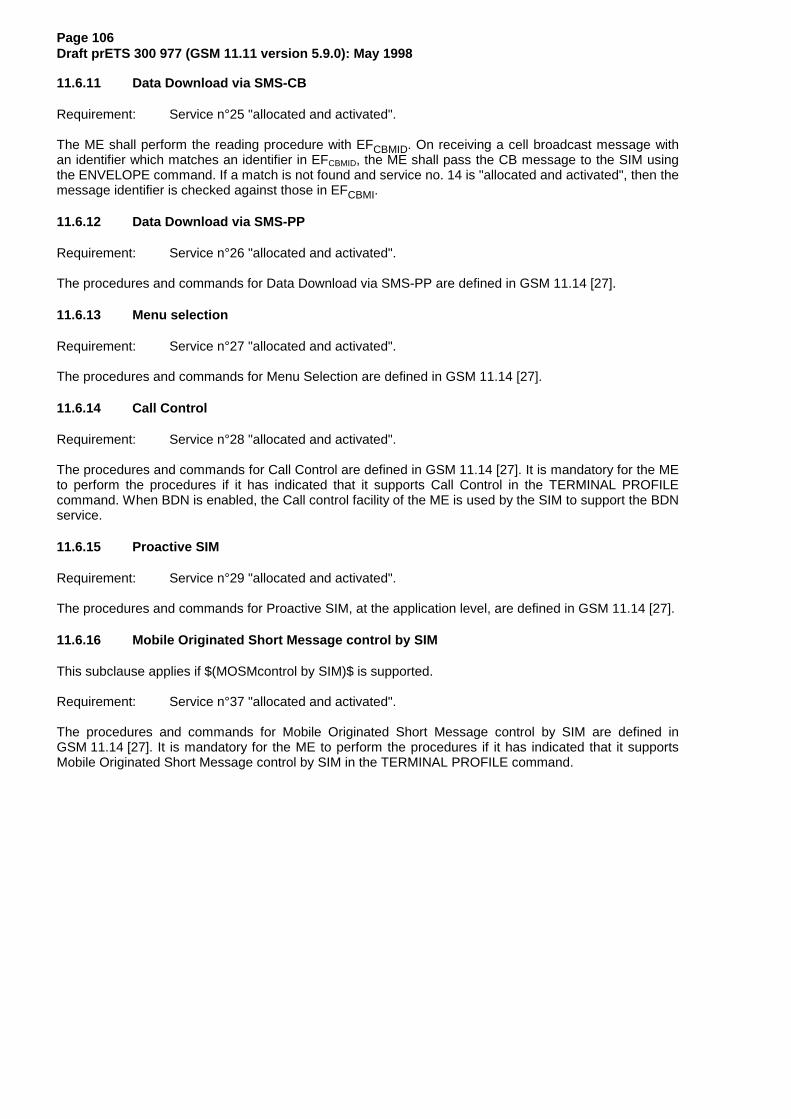
Page 106Draft prETS 300 977 (GSM 11.11 version 5.9.0): May 1998
11.6.11 Data Download via SMS-CB
Requirement: Service n°25 "allocated and activated".
The ME shall perform the reading procedure with EFCBMID. On receiving a cell broadcast message withan identifier which matches an identifier in EFCBMID, the ME shall pass the CB message to the SIM usingthe ENVELOPE command. If a match is not found and service no. 14 is "allocated and activated", then themessage identifier is checked against those in EFCBMI.
11.6.12 Data Download via SMS-PP
Requirement: Service n°26 "allocated and activated".
The procedures and commands for Data Download via SMS-PP are defined in GSM 11.14 [27].
11.6.13 Menu selection
Requirement: Service n°27 "allocated and activated".
The procedures and commands for Menu Selection are defined in GSM 11.14 [27].
11.6.14 Call Control
Requirement: Service n°28 "allocated and activated".
The procedures and commands for Call Control are defined in GSM 11.14 [27]. It is mandatory for the MEto perform the procedures if it has indicated that it supports Call Control in the TERMINAL PROFILEcommand. When BDN is enabled, the Call control facility of the ME is used by the SIM to support the BDNservice.
11.6.15 Proactive SIM
Requirement: Service n°29 "allocated and activated".
The procedures and commands for Proactive SIM, at the application level, are defined in GSM 11.14 [27].
11.6.16 Mobile Originated Short Message control by SIM
This subclause applies if $(MOSMcontrol by SIM)$ is supported.
Requirement: Service n°37 "allocated and activated".
The procedures and commands for Mobile Originated Short Message control by SIM are defined inGSM 11.14 [27]. It is mandatory for the ME to perform the procedures if it has indicated that it supportsMobile Originated Short Message control by SIM in the TERMINAL PROFILE command.

Page 107Draft prETS 300 977 (GSM 11.11 version 5.9.0): May 1998
Annex A (normative): Plug-in SIM
This annex specifies the dimensions of the Plug-in SIM as well as the dimensions and location of thecontacts of the Plug-in SIM. For further details of the Plug-in SIM see clause 4.
4 m ax
6 m in
11,62 m ax
13,62 m in
7,5
P1
P2 P3
20,8
2,75
max
4,45
min
5,29
max
6,99
min
7,83
max
9,53
min
10,3
7 m
ax
12,0
7 m
in
3 ,3
0
3 ±0,1
3±0,1
15±0
,1
(6 ,25)
U p p e r e d g e
Left
edge
(16,
48)
25±0 ,1
R1 0
,1+_
R1 0,1+_
R1 0,1+_
R1 0,1+_
R1 0,1+_
NOTE: The Plug-in SIM may be "obtained" by cutting away excessive plastic of an ID-1 SIM. Thevalues in parenthesis in figure A.1 show the positional relationship between the Plug-in and theID-1 SIM and are for information only.
Figure A.1: Plug-in SIM

Page 108Draft prETS 300 977 (GSM 11.11 version 5.9.0): May 1998
Annex B (normative): Coding of Alpha fields in the SIM for UCS2
This annex applies only if $(UCS2)$ is supported.
If 16 bit UCS2 characters as defined in ISO/IEC 10646 [31] are being used in an alpha field, the codingcan take one of three forms. If the ME supports UCS2 coding of alpha fields in the SIM, the ME shallsupport all three coding schemes for character sets containing 128 characters or less; for character setscontaining more than 128 characters, the ME shall at least support the first coding scheme. If the alphafield record contains GSM default alphabet characters only, then none of these schemes shall be used inthat record. Within a record, only one coding scheme, either GSM default alphabet, or one of the threedescribed below, shall be used.
1) If the first octet in the alpha string is '80', then the remaining octets are 16 bit UCS2 characters, withthe more significant octet (MSO) of the UCS2 character coded in the lower numbered octet of thealpha field, and the less significant octet (LSO) of the UCS2 character is coded in the highernumbered alpha field octet, i.e. octet 2 of the alpha field contains the more significant octet (MSO)of the first UCS2 character, and octet 3 of the alpha field contains the less significant octet (LSO) ofthe first UCS2 character (as shown below). Unused octets shall be set to 'FF', and if the alpha fieldis an even number of octets in length, then the last (unusable) octet shall be set to 'FF'.
Example 1
Octet 1 Octet 2 Octet 3 Octet 4 Octet 5 Octet 6 Octet 7 Octet 8 Octet 9'80' Ch1MSO Ch1LSO Ch2MSO Ch2LSO Ch3MSO Ch3LSO 'FF' 'FF'
2) If the first octet of the alpha string is set to '81', then the second octet contains a value indicating thenumber of characters in the string, and the third octet contains an 8 bit number which defines bits 15to 8 of a 16 bit base pointer, where bit 16 is set to zero, and bits 7 to 1 are also set to zero. Thesesixteen bits constitute a base pointer to a “half-page” in the UCS2 code space, to be used withsome or all of the remaining octets in the string. The fourth and subsequent octets in the stringcontain codings as follows; if bit 8 of the octet is set to zero, the remaining 7 bits of the octet containa GSM Default Alphabet character, whereas if bit 8 of the octet is set to one, then the remainingseven bits are an offset value added to the 16 bit base pointer defined earlier, and the resultant 16bit value is a UCS2 code point, and completely defines a UCS2 character.
Example 2
Octet 1 Octet 2 Octet 3 Octet 4 Octet 5 Octet 6 Octet 7 Octet 8 Octet 9'81' '05' '13' '53' '95' 'A6' 'XX' 'FF' 'FF'
In the above example;
- Octet 2 indicates there 5 characters in the string
- Octet 3 indicates bits 15 to 8 of the base pointer, and indicates a bit pattern of 0hhh hhhhh000 0000 as the 16 bit base pointer number. Bengali characters for example start at codeposition 0980 (0000 1001 1000 0000), which is indicated by the coding '13' in octet 3 (shownby the italicised digits).
- Octet 4 indicates GSM Default Alphabet character ‘53’, i.e. "S".
- Octet 5 indicates a UCS2 character offset to the base pointer of '15', expressed in binary asfollows 001 0101, which, when added to the base pointer value results in a sixteen bit valueof 0000 1001 1001 0101, i.e. '0995', which is the Bengali letter KA.
Octet 8 contains the value 'FF', but as the string length is 5, this a valid character in thestring, where the bit pattern 111 1111 is added to the base pointer, yielding a sixteen bit valueof 0000 1001 1111 1111 for the UCS2 character (i.e. '09FF').
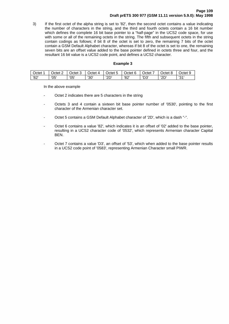
Page 109Draft prETS 300 977 (GSM 11.11 version 5.9.0): May 1998
3) If the first octet of the alpha string is set to '82', then the second octet contains a value indicatingthe number of characters in the string, and the third and fourth octets contain a 16 bit numberwhich defines the complete 16 bit base pointer to a “half-page” in the UCS2 code space, for usewith some or all of the remaining octets in the string. The fifth and subsequent octets in the stringcontain codings as follows; if bit 8 of the octet is set to zero, the remaining 7 bits of the octetcontain a GSM Default Alphabet character, whereas if bit 8 of the octet is set to one, the remainingseven bits are an offset value added to the base pointer defined in octets three and four, and theresultant 16 bit value is a UCS2 code point, and defines a UCS2 character.
Example 3
Octet 1 Octet 2 Octet 3 Octet 4 Octet 5 Octet 6 Octet 7 Octet 8 Octet 9'82' '05' '05' '30' '2D' '82' 'D3' '2D' '31'
In the above example
- Octet 2 indicates there are 5 characters in the string
- Octets 3 and 4 contain a sixteen bit base pointer number of '0530', pointing to the firstcharacter of the Armenian character set.
- Octet 5 contains a GSM Default Alphabet character of '2D', which is a dash "-".
- Octet 6 contains a value '82', which indicates it is an offset of '02' added to the base pointer,resulting in a UCS2 character code of '0532', which represents Armenian character CapitalBEN.
- Octet 7 contains a value 'D3', an offset of '53', which when added to the base pointer resultsin a UCS2 code point of '0583', representing Armenian Character small PIWR.

Page 110Draft prETS 300 977 (GSM 11.11 version 5.9.0): May 1998
Annex C (informative): FDN/BDN Procedures
AT R
G et R esponse
Verify CHV1(if not disabled)
G e t R e sponse(ev alu ation o f
inva lida tion flag )
G e t R e sponse(ev alu ation o f
inva lida tion flag )
(see note1)
(see note1)
not invalidated(see note 2 )
inva lida ted
1
M E: unrestric ted opera tion
S IMPhase?
Phase 2
Phase 1
S tatus EF
and E FLOCIIM SI
M E: unrestric ted operation
Select D FG SM
S e le c t E FLO C I
S e le c t E FIM SI
Phase 2+ Perform ProfileDownload
(see note3)
NOTE 1: In case of enabled FDN and/or enabled BDN, the EF has been invalidated by the SIM at nolater than this stage.
NOTE 2: Invalidation of only one of the two EFs is not allowed for FDN and BDN.
NOTE 3: For SIMs with enabled BDN this procedure is used to check whether the ME supports the CallControl by the SIM facility.
Figure C.1: Example of an Initialization Procedure of a FDN/BDN SIM (see 11.2.1)

Page 111Draft prETS 300 977 (GSM 11.11 version 5.9.0): May 1998
SIM capabilityrequest
MEsupports
CC ?
1
noyes
MEsupports all
enabled services(see note 6)
?
MEsupports FDN
and FDN isenabled
?
no no
yes yes
RehabilitateEFLOCI and EF IMSI
RehabilitateEFLOCI and EF IMSI
(note 4) (note 4)
EFsrehabilitated
?
EFsrehabilitated
?
no
yes
(note 5)no
(note 5)
yes
no opera tion FD N opera tionrestric ted or unres tric tedopera tion , accord ing tothe s ta te (enab led/d isab led)o f the various serv ices (FD N , C C )
NOTE 4: In case of "BDN enabled", the SIM only allows rehabilitation of the EFIMSI and EFLOCI, if the MEhas indicated its CC-capability to the SIM (by PROFILE_DOWNLOAD).
NOTE 5: Possibility for future "restricting" services to use the internal SIM mechanism of invalidation ofEFIMSI and EFLOCI.
NOTE 6: If the ME does not support all enabled services (e.g. FDN, BDN), it does not operate. In case ofenabled BDN, the support of the "Call Control Feature" by the ME is sufficient for operation. Forfuture use, there may be additional "restricting" services, which are not known to the ME. In thatcase the ME will perform the subsequent rehabilitation procedure but will fail to rehabilitateEFIMSI and EFLOCI (see note 4).
Figure C.1: Example of an Initialization Procedure of a FDN/BDN SIM (continued)

Page 112Draft prETS 300 977 (GSM 11.11 version 5.9.0): May 1998
BDN capabil i tyrequest
FDN capabil i tyrequest
Fig C.2: SIM capability request
Select DF TELECOM
Select EF BDN
BDNallocated and
activated?
yes no
Select EF SST
Read EF SST
Get Response(evaluation of
invalidation flag)
EFBDNinvalidated
?
no
No BDN SIM
yes
BDN disabledBDN enabled
Figure C.3: BDN capability request (see 11.5.1)

Page 113Draft prETS 300 977 (GSM 11.11 version 5.9.0): May 1998
(see note 7)
yes
Select EFSST
Read EFSST
Telecom
SelectDF
ADN
SelectEF
no
no
yes noinvalidated
EF
?
ADN
FDN enabled FDN disabled No FDN SIM
FDN
allocated andactivated
?
Get Response(evaluation ofinvalidation fla g)
ADNallocated
andactivated
?
yes
NOTE 7: In this case FDN is enabled without the possibility of disabling.
Figure C.4: FDN capability request (see 11.5.1)

Page 114Draft prETS 300 977 (GSM 11.11 version 5.9.0): May 1998
R ehabilitateEF
R ehabilitate
IM S IEF
Select EFL O C I
LO C I
Select EFIM S I
(Note 8)
(Note 8)
R ehabilita te
IM S IEF LO C IEF
NOTE 8: If BDN is enabled in the SIM, and if the Profile download procedure has not indicated that theME supports Call Control, the EF is not rehabilitated by the SIM.
Figure C.5: Procedure to rehabilitate GSM files

Page 115Draft prETS 300 977 (GSM 11.11 version 5.9.0): May 1998
yes
FDNallocated and
activated?
no
FDN enab led
no
no
yes
ADNallocated
andactivated
?
FDN not enab led
invalidated
EF
?
ADN
yes
Boolean equation:
FD = FDA . (NOT(ADA) + ADA . ADI)
with
FD = FDN enabled
FDA = FDN allocated and activated
ADA = ADN allocated and activated
ADI = EFADN invalidated
Figure C.6: Coding for state of FDN
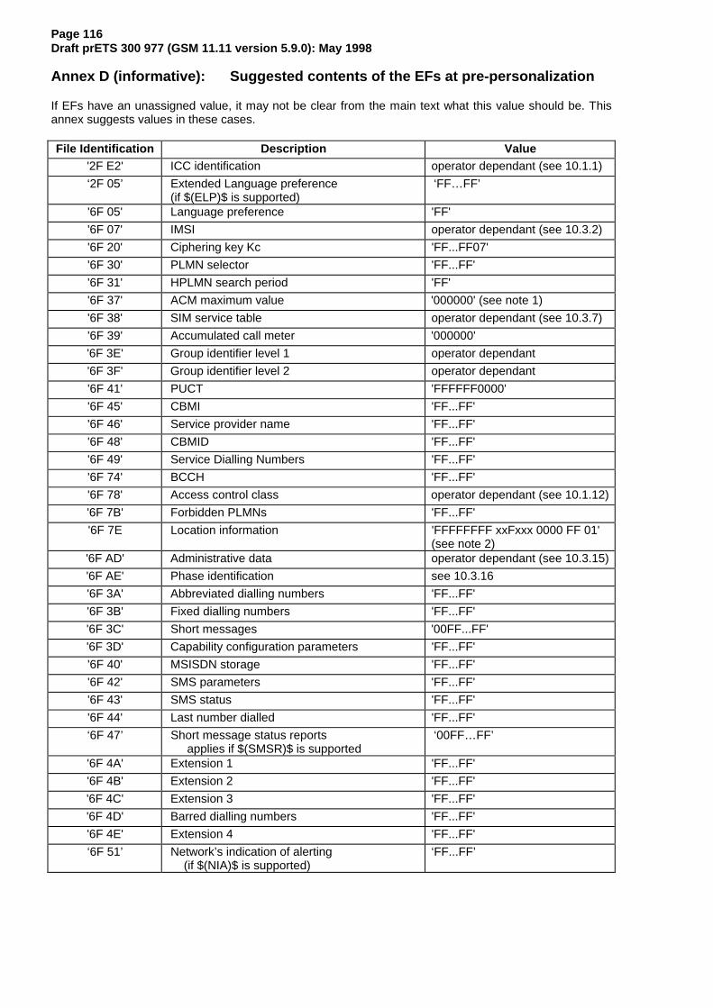
Page 116Draft prETS 300 977 (GSM 11.11 version 5.9.0): May 1998
Annex D (informative): Suggested contents of the EFs at pre-personalization
If EFs have an unassigned value, it may not be clear from the main text what this value should be. Thisannex suggests values in these cases.
File Identification Description Value'2F E2' ICC identification operator dependant (see 10.1.1)
‘2F 05’ Extended Language preference(if $(ELP)$ is supported)
‘FF…FF’
'6F 05' Language preference 'FF'
'6F 07' IMSI operator dependant (see 10.3.2)
'6F 20' Ciphering key Kc 'FF...FF07'
'6F 30' PLMN selector 'FF...FF'
'6F 31' HPLMN search period 'FF'
'6F 37' ACM maximum value '000000' (see note 1)
'6F 38' SIM service table operator dependant (see 10.3.7)
'6F 39' Accumulated call meter '000000'
'6F 3E' Group identifier level 1 operator dependant
'6F 3F' Group identifier level 2 operator dependant
'6F 41' PUCT 'FFFFFF0000'
'6F 45' CBMI 'FF...FF'
'6F 46' Service provider name 'FF...FF'
'6F 48' CBMID 'FF...FF'
'6F 49' Service Dialling Numbers 'FF...FF'
'6F 74' BCCH 'FF...FF'
'6F 78' Access control class operator dependant (see 10.1.12)
'6F 7B' Forbidden PLMNs 'FF...FF'
'6F 7E Location information 'FFFFFFFF xxFxxx 0000 FF 01'(see note 2)
'6F AD' Administrative data operator dependant (see 10.3.15)
'6F AE' Phase identification see 10.3.16
'6F 3A' Abbreviated dialling numbers 'FF...FF'
'6F 3B' Fixed dialling numbers 'FF...FF'
'6F 3C' Short messages '00FF...FF'
'6F 3D' Capability configuration parameters 'FF...FF'
'6F 40' MSISDN storage 'FF...FF'
'6F 42' SMS parameters 'FF...FF'
'6F 43' SMS status 'FF...FF'
'6F 44' Last number dialled 'FF...FF'
‘6F 47’ Short message status reports applies if $(SMSR)$ is supported
‘00FF…FF’
'6F 4A' Extension 1 'FF...FF'
'6F 4B' Extension 2 'FF...FF'
'6F 4C' Extension 3 'FF...FF'
'6F 4D' Barred dialling numbers 'FF...FF'
'6F 4E' Extension 4 'FF...FF'
‘6F 51’ Network’s indication of alerting (if $(NIA)$ is supported)
‘FF...FF’

Page 117Draft prETS 300 977 (GSM 11.11 version 5.9.0): May 1998
NOTE 1: The value '000000' means that ACMmax is not valid, i.e. there is no restriction on theACM. When assigning a value to ACMmax, care should be taken not to use values tooclose to the maximum possible value 'FFFFFF', because the INCREASE commanddoes not update EFACM if the units to be added would exceed 'FFFFFF'. This couldaffect the call termination procedure of the Advice of Charge function.
NOTE 2: xxFxxx stands for any valid MCC and MNC, coded according to GSM 04.08 [15].

Page 118Draft prETS 300 977 (GSM 11.11 version 5.9.0): May 1998
Annex E (Informative): SIM application Toolkit protocol diagrams.
The diagrams in this annex are intended to illustrate the data protocols of the SIM toolkit application invarious situations. The SIM application is shown as initiated by SMS Data Download messages. Otherpossibilities exist (as defined in GSM 11.14) such as data entry from a menu selection.
Case 1: Simple
Network M EG S MSIM
SIMApplication
S M S SIM
_Data_Down load /C lass_2
ENV(SMS)
(SMS)
(‘9000’)
‘9000’
SMS Ack
This shows the simple case where an SMS for SIM updating is received from the network, passed to theSIM by the ME and processed immediately by the SIM application. This requires no ME action except toacknowledge the SMS.

Page 119Draft prETS 300 977 (GSM 11.11 version 5.9.0): May 1998
Case 2: Simple with short delay
Network M EG S MSIM
SIMAppl
ENV(SMS)
(SMS)
(‘9000’)
‘9000’
SMS Ack
‘60’ (‘60’)
‘60’ (‘60’)
S M S SIM
_Data_Down load /C lass_2
This shows the simple case where an SMS for SIM updating is received from the network, passed to theSIM by the ME and which requires some time to process by the SIM application. The processing time is"not long" and is obtained by the SIM application sending "null procedure bytes" to the ME. Each byte hasthe effect of restarting the work waiting time so that the ME does not abort the transaction before the SIMapplication has finished processing the command(s) sent in the SMS.
Guidelines on timings:
1. The SMS Ack must be sent back before the network times out and sends the SMS again.
2. Use of null procedure bytes must not be excessive as during this time the ME is unable to issue normalGSM commands to the SIM.

Page 120Draft prETS 300 977 (GSM 11.11 version 5.9.0): May 1998
Case 3: Simple with short delay and SIM Acknowledgement
Network M EG S MSIM
SIMAppl
ENV(SMS)
(SMS)
(‘9F10’)
‘9F10’
SMS Ack (wi thSIM Ack)
‘60’ (‘60’)
‘60’ (‘60’)
S M S SIM
_Data_Down load /C lass_2
Get Response (16 bytes)
(SIM Ack)
SIM Ack
This shows the same case as previously where an SMS for SIM updating is received from the network,passed to the SIM by the ME and which requires some time to process by the SIM application. However inthis case the SIM application has SIM acknowledgement data to include in the SMS acknowledgementbeing returned to the network by the ME.
Guideline on timings:
The SMS Ack must be sent back before the network times out and sends the SMS again.

Page 121Draft prETS 300 977 (GSM 11.11 version 5.9.0): May 1998
Case 4: A Toolkit command generated by the SIM application as a result of an SMS from thenetwork
Network M EG S MSIM
SIMApplication
ENV(SMS)
F E T C H
(SMS)
(FETCH)
(Command)
C o m m a n d
(‘91XX’)
(TERMINAL RESPONSE)
‘91XX’
(‘9000’)
SMS Ack
TERMINAL RESPONSE
‘60’
‘9000’
(‘60’)
S M S SIM
_Data_Down load /C lass_2
‘60’ (‘60’)
This shows the case where an SMS for SIM updating is received from the network, passed to the SIM bythe ME and processed by the SIM application which then generates a command for action by the ME (e.g.PLAYTONE).
NOTE: If a positive acknowledgement to the network of completion of execution of theinstructions given in the SMS message is required then the SIM application can issuea command to the ME to send a MO SMS.

Page 122Draft prETS 300 977 (GSM 11.11 version 5.9.0): May 1998
Case 5: A normal GSM command requires processing before the ME can respond to the 91XX fromthe SIM
Network M EG S MSIM
SIMApplication
(SMS)
(‘91XX’)
ENV(SMS)
‘91XX’
SMS Ack
F E T C H
(FETCH)
(Command)
C o m m a n d
GSM Command
‘91XX’
S M S SIM
_Data_Down load /C lass_2
(TERMINAL RESPONSE)
(‘9000’)
TERMINAL RESPONSE
‘9000’
This shows the case where an SMS for SIM updating is received from the network, passed to the SIM bythe ME and processed by the SIM application which then generates a command for action by the ME (e.g.PLAYTONE). However a normal GSM command requires processing before the ME can FETCH thecommand which the SIM is waiting to give it. The response to the normal GSM command is '91XX' in thiscase to remind the ME of the outstanding SIM application command request.
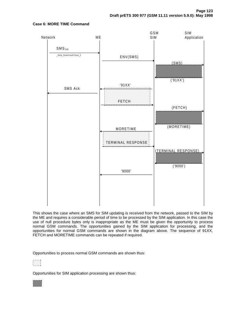
Page 123Draft prETS 300 977 (GSM 11.11 version 5.9.0): May 1998
Case 6: MORE TIME Command
Network M EG S MSIM
SIMApplication
(SMS)
(‘91XX’)
ENV(SMS)
‘91XX’SMS Ack
F E T C H
(FETCH)
(MORETIME)MORETIME
(TERMINAL RESPONSE)
(‘9000’)
TERMINAL RESPONSE
‘9000’
S M S SIM
_Data_Down load /C lass_2
This shows the case where an SMS for SIM updating is received from the network, passed to the SIM bythe ME and requires a considerable period of time to be processed by the SIM application. In this case theuse of null procedure bytes only is inappropriate as the ME must be given the opportunity to processnormal GSM commands. The opportunities gained by the SIM application for processing, and theopportunities for normal GSM commands are shown in the diagram above. The sequence of 91XX,FETCH and MORETIME commands can be repeated if required.
Opportunities to process normal GSM commands are shown thus:
Opportunities for SIM application processing are shown thus:
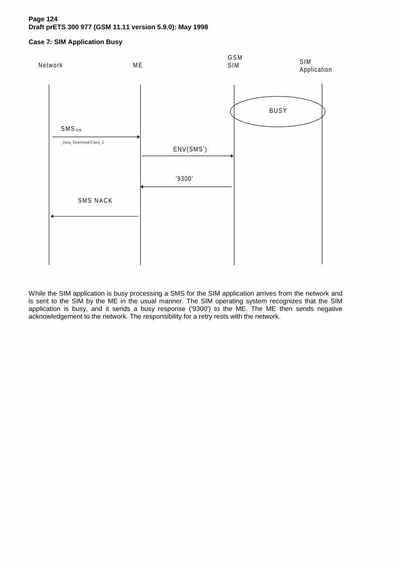
Page 124Draft prETS 300 977 (GSM 11.11 version 5.9.0): May 1998
Case 7: SIM Application Busy
Network M EG S MSIM SIM
Application
ENV(SMS’)
‘9300’
BUSY
SMS NACK
S M S SIM
_Data_Down load /C lass_2
While the SIM application is busy processing a SMS for the SIM application arrives from the network andis sent to the SIM by the ME in the usual manner. The SIM operating system recognizes that the SIMapplication is busy, and it sends a busy response ('9300') to the ME. The ME then sends negativeacknowledgement to the network. The responsibility for a retry rests with the network.

Page 125Draft prETS 300 977 (GSM 11.11 version 5.9.0): May 1998
Annex F (informative): Bibliography
1) EN 726-3 (1994): "Terminal Equipment (TE); Requirements for IC cards andterminals for telecommunication use Part 3: Application independent cardrequirements".
2) EN 726-4 (1994): "Terminal Equipment (TE); Requirements for IC cards andterminals for telecommunication use Part 4: Application independent cardrelated terminal requirements".
3) ISO/IEC 7816-3/A2 (1994): "Identification cards - Integrated circuit(s) cards withcontacts, Part 3: Electronic signals and transmission protocols": "Protocol typeselect".

Page 126Draft prETS 300 977 (GSM 11.11 version 5.9.0): May 1998
Annex G (informative): Change history
This annex lists all change requests approved for this document since the first phase2+ version wasapproved by ETSI SMG.
SMG# SMGtdoc
SMG9tdoc
VERS CR RV PH CAT SUBJECT ResultingVersion
S16 709/95 154/95 4.15.0 A008 r96 1 SIM Speed Enhancement 5.0.0
S17 062/96 147/95 5.0.0 A006 r96 B Service Dialling Numbers 5.1.0
S17 060/96 06/96 5.0.0 A009 r96 B ASCI for VGCS and VBS 5.1.0
S17 060/96 06/96 5.0.0 A010 r96 B ASCI for eMLPP 5.1.0
S17 059/96 204/95r 5.0.0 A013 r96 C Interaction between FDNs and ADNs 5.1.0
S17 061/96 05/96 5.0.0 A014 r96 D Correction of baud rate for SIM Speed enhancement 5.1.0
S18 263/96 57/96 5.1.0 A011 3 r96 B SIM Application Toolkit protocol enhancements 5.2.0
S18 260/96 45/96 5.1.0 A016 r96 A SIM presence detection clarification 5.2.0
S18 261/96 54/96 5.1.0 A018 r96 A Reponse codes and coding of SIM service table 5.2.0
S18 262/96 55/96 5.1.0 A020 r96 A Reference to International Standards 5.2.0
S19 374/96 102/96 5.2.0 A012 r96 C Contacting elements 5.3.0
S19 373/96 105/96 5.2.0 A023 r96 A Clarification of clock stop timing 5.3.0
S19 409/96 107/96 5.2.0 A024 1 r96 B Emergency Call Codes (ECC) 5.3.0
S19 374/96 108/96 5.2.0 A025 r96 C Using ranges of CBMIs 5.3.0
S20 580/96 206/96 5.3.0 A021 r96 B Barred Dialling Numbers 5.4.0
S20 734/96 197/96 5.3.0 A026 r96 B Addition of Cooperative Network List EF 5.4.0
S20 734/96 197/96 5.3.0 A027 r96 B Addition of ME Depersonalisation feature and EF 5.4.0
S20 702/96 207/96 5.3.0 A031 r96 D RFU bit taken into use in GSM 11.12 5.4.0
s21 101/97 97/079 5.4.0 A032 2 r96 D Ammendment to BDN diagrams in Annex B 5.5.0
s21 101/97 97/086 5.4.0 A033 1 r96 B DFs for MSS/ PCS1900/other use 5.5.0
s21 101/97 97/056 5.4.0 A034 r96 C Reading of EFDCK during SIM initialisation 5.5.0
s21 101/97 97/058 5.4.0 A036 r96 D Administrative Access Conditions 5.5.0
s21 101/97 97/059 5.4.0 A037 r96 B Format of EFCNL to include fields for Corporate Personal.Code
5.5.0
s21 101/97 97/089 5.4.0 A041 r96 B Administrative Data field 5.5.0
s22 356/97 183/97 5.5.0 A042 r97 B Extended language preference 5.6.0
s22 356/97 163/97 5.5.0 A044 1 r96 A Clarification of electrical/mechanical SIM/ME interface 5.6.0
s22 356/97 179/97 5.5.0 A045 r96 D Security procedures for 2nd level; DFs located under DFGSM
5.6.0
s22 356/97 187/97 5.5.0 A047 r96 F Number of bytes returned after a SELECT command 5.6.0
s22 356/97 093/97 5.5.0 A048 r96 D Editorial corrections regarding serivce table and "radiointerface"
5.6.0
s22 356/97 109/97 5.5.0 A049 r96 F Update Access condition of EFDCK (aligns 11.11 withGSM 02.22)
5.6.0
s23 788/97 97/249 5.6.0 A046 2 r97 B Short Message Status Reports 5.7.0
s23 788/97 97/243 5.6.0 A050 r96 F Addition of reference to SDN and BDN in the descriptionof EFCCP
5.7.0
s23 788/97 97/259 5.6.0 A051 1 r97 C SIM and ME behaviour when SIM is disabled and blocked 5.7.0
s23 788/97 97/262 5.6.0 A053 r96 F Response data following an ENVELOPE command 5.7.0
s23 788/97 97/260 5.6.0 A054 r96 F Coding of EFPhase 5.7.0
s23 788/97 97/271 5.6.0 A055 r97 C Changes to Dialling Number Files and extensions 5.7.0
s23 788/97 97/261 5.6.0 A056 r97 B Network's indication of alerting in the MS 5.7.0
s24 97-886 97/365 5.7.0 A052 2 r97 b Introduction of UCS2 5.8.0
s24 97-886 97/383 5.7.0 A057 r97 c MO SMS control by SIM 5.8.0
s25 98-0157 98p094 5.8.0 A061 1 r96 A Clarification of removal of the SIM 5.9.0

Page 127Draft prETS 300 977 (GSM 11.11 version 5.9.0): May 1998
History
Document history
December 1996 Unified Approval Procedure UAP 62: 1996-12-30 to 1997-04-25
April 1997 One-step Approval Procedure OAP 9742 1997-05-23 to 1997-10-17(Second Edition)
August 1997 One-step Approval Procedure OAP 9752: 1997-08-29 to 1997-12-26(Third Edition)
October 1997 Second Edition
January 1998 Third Edition
May1998 One-step Approval Procedure OAP 9841: 1998-05-20 to 1998-10-16(Fourth Edition)