euf-net-t1756 - rf power solutions for industry-avionics
TRANSCRIPT

LAURENT GAUTHIER - FAE - RF POWERMARCH 22nd, 2016
EUF-NET-T1756
RF POWER SOLUTIONS FOR INDUSTRY, AVIONICS, MILITARY,
CELLULAR AND COOKING MARKETS
1
Agenda
• RF Org
• RF Power for Industry
• RF Power for Avionics
• RF Power for Mobile Radio
• RF Power for RF Cooking Oven
• RF Power for Cellular
• RF Power for Military applications

2
NXP - Freescale merger : Impact on RF Power
FREESCALERF Power
YESTERDAY TODAY
NXPRF Power
NXP sold to Jianguang Asset Management Co. Ltd its RF POWER DIVISION
NXP acquired Freescale including its RF POWER DIVISION
NXPRF Power
AMPLEONRF Power
MRF MRFBLF BLF

3
NXP 5 BUSINESS UNITS Security & Connectivity
Digital Networking
Best-in-class security, contactless performance and the most complete solutions to produce unmatched mobile and IoT solutions
High-performance multicore solutions that transport, analyze and secure
data from the edge of the network to the cloud
Automotive
RF Power
Sensor and processing technology driving all aspects of the secure connected cars of today and the autonomous cars of tomorrow
Solutions spanning the wireless infrastructure, industrial, broadcast, mobile radio, aerospace & defense and cooking markets
Standard ProductsLeading supplier for all major
automotive, identification, wireless infrastructure, industrial, mobile,
lighting, consumer and computing manufacturers

4
NXP RF Power Markets
• Picocells• Pre-drivers • Novel PA components
Small Signal RF
• Base Stations• Repeaters• From GSM to LTE
Cellular Power Amplifiers
Military & Defense
• FM• VHF TV• UHF TV
Broadcast
• Handheld• Vehicle• Base stations
Land Mobile Radio
• Distance Measuring• Transponders• L- and S-band Radars
Commercial Avionics
RF Cooking
• RF Ovens:- Commercial- Consumer
ISM (Industrial, Scientific, Medical)
• Radar• Communications• Electronic Warfare
• Laser/Plasma generator• Medical• Particle Accelerators• Industrial Heating
5
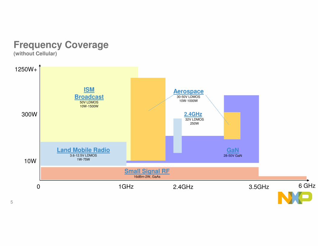
Frequency Coverage(without Cellular)
0 3.5GHz1GHz
1250W+
ISMBroadcast
50V LDMOS10W-1500W
Aerospace30-50V LDMOS
10W-1000W
6 GHz
300W
10W
Small Signal RF16dBm-2W, GaAs
Land Mobile Radio3.6-12.5V LDMOS
1W-75W
2.4GHz
32V LDMOS
250W
GaN28-50V GaN
2.4GHz

6
RF POWER FOR INDUSTRY
7
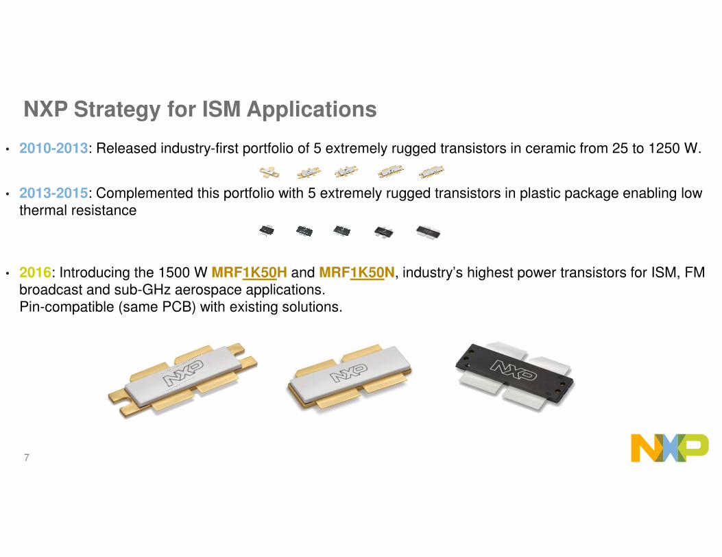
NXP Strategy for ISM Applications
• 2010-2013: Released industry-first portfolio of 5 extremely rugged transistors in ceramic from 25 to 1250 W.
• 2013-2015: Complemented this portfolio with 5 extremely rugged transistors in plastic package enabling low thermal resistance
• 2016: Introducing the 1500 W MRF1K50H and MRF1K50N, industry’s highest power transistors for ISM, FM broadcast and sub-GHz aerospace applications. Pin-compatible (same PCB) with existing solutions.

8
NXP Differentiator : More Power with Plastic Packaging
1250 W 600 W
Top benefits of plastic over ceramic:
–Lower thermal resistance (30%), enabling smaller heatsink or better reliability
–Tighter dimensional tolerance, enabling assembly automation
–Same thermal expansion (copper on copper), enabling better reliability (no CTE mismatch at solder joint)
–Tin-platted instead of gold-platted: more reliable soldering
–Over-molded instead of air-cavity: enables washing the board after assembly

9
Execution
Production
Proposal
Right edge= Qualification date
Planning
300W
600W
1250W
MRFE6VP100H
Available Now
MRFE6VP61K25H
MRFE6VP5600H
MRFE6VP6300H
25W
1 to 600 MHz 1.25 kW
1 to 500 MHz 600W
1 to 600 MHz
1 to 2000 MHz 100W
1 to 600 MHz 300W
P1dB
MRFE6VS25L
•Smaller package than MRFE6VP5600H•Lower Rth
1 to 600 MHz 600W
MRFE6VP5300N
300W
MRFE6VP5150N
1 to 600 MHz 1.25 kW•Plastic version of MRFE6VP61K25H
•Lower Rth
1 to 2000 MHz 25W
MRFE6VS25N
1 to 2000 MHz 25W
MRFE6VP61K25N
MRFE6VP6600N
1500W
2016
1 to 600 MHz 150W
100 to 2400 MHz 100W
AFG24S100H
50V LDMOS
Plastic
50V GaN
ISM : <600 MHz
25W
1.5kW to 500 MHz
MRF1K50N
MRF1K50H
All watts are CW

10
MRF1K50H / MRF1K50N1.50 kW LDMOS Transistor
• Unmatched Input and Output
• Push-Pull
• Housed in an NI-1230 air-cavity ceramic package (H version) or OM-1230 over molded plastic (N version)
− 30% lower Rjc with plastic version
• Extreme Ruggedness: 65:1 VSWR
• Product Longevity Program: warranted availability until 2031
• Recommended Driver: MRFE6VS25N (25W)
Board Frequency
(MHz)
Example of
application
Power
(W)
Gain
(dB)
Drain Eff.
(%)
81.36 MHz Laser 1500 CW 23.3 77.4
87.5 MHz
FM (88-108 MHz
circuit)
1345 CW 23.5 81.2
98 MHz 1526 CW 24.1 79.4
108 MHz 1389 CW 23.6 80.0
Planned Reference Circuits
1.8-500 MHz
1500 W CW
50V
Q2 2016

11
Comparison with Existing Solutions
MRFE6VP61K25H Competitor MRF1K50H
Rated Output power 1250W 1400W 1500W
Narrowband performance @ 81.36 MHz
1350W CW23.5 dB gain
75 % eff.
1200 W CW27.1 dB gain
77.8 % eff.
1500 W CW23.3 dB gain
77.4% eff.
Wideband performance over 88-108 MHz
1250W CW23 dB gain
75 % eff.
1320 W CW22.5 dB gain
tbd eff.
1520 W CW24.1 dB gain
79.4% eff.
VSWR max 65:1 65:1 65:1

12
MRF1K50H Performance Comparison @ 81.36 MHz
Pin vs Pout
0
200
400
600
800
1000
1200
1400
1600
1800
0,5 1,5 2,5 3,5 4,5 5,5 6,5 7,5
MRFE6VP61K25H MRF1K50H in board as is
MRF1K50H in retuned board
22
23
24
25
26
27
28
500 700 900 1100 1300 1500
0%
10%
20%
30%
40%
50%
60%
70%
80%
90%
0,5 1,5 2,5 3,5 4,5 5,5 6,5 7,5
Gain vs Pout
Efficiency vs Pin
W
W
W
W
dB
Vdd=50V, Idq=200mA, Vg=2.46VPulse width 400µs / 60% duty cycle
60%
62%
64%
66%
68%
70%
72%
74%
76%
78%
80%
1000 1100 1200 1300 1400 1500 1600 W
Efficiency vs Pout
Data taken on 81.36 MHz MRFE6VP61K25H planar balun
reference circuit
Drop-in with MRFE6VP61K25H, but better performance with retuning.

13
250W
Available Now
MRF6V13250H
1300 MHz 250W CW
P1dB
350W
2015
100 to 2400 MHz 100W
MRFE6VP100H100W
1 to 2000 MHz 100W
900-1300 MHz 350W CW
MRF8VP13350N
AFG24S100H
ISM : 915 MHz & 1300 MHz
All watts are CW.
2016 2017
Execution
Production
Proposal
Right edge= Qualification date
Planning
50V LDMOS
Plastic
50V GaN

14
MRF8VP13350N350 W LDMOS Transistor in Plastic
Designed for industrial heating/welding at 915 MHz and particle accelerators at 1300 MHz
• Input pre-matched
• Push Pull
• Housed in OM-780 over-molded plastic package
• High ruggedness: 10:1 VSWR
• Product Longevity Program: warranted availability until 2030
• Recommended driver: MRFE6VS25N (25W)
Available Reference Circuits
NEW
Board Frequency(MHz)
Example of application
Power (W)
Gain(dB)
Drain Eff. (%)
Size (inch)
915 MHz Indus. heating 350 CW 20.7 67.5 1.6 x 2.0
1300 MHz Synchrotron 350 CW 17.2 57 3 x 4
700-1300 MHz
350 W CW
50V

15
AFG24S100H100 W CW Wideband GaN Transistor
• Advanced GaN on SiC
• 100W CW across 100-2450 MHz
• Housed in NI-360 air-cavity ceramic package
• High Ruggedness: 20:1 VSWR
• Product Longevity Program: warranted availability until 2025
• Typical Applications
− EMC testers
− Scientific research
− Professional mobile radios
− Wideband drivers
− General purpose wideband amplifiers
Planned Reference Circuits
Board Frequency(MHz)
Example of application
Power (W)
Gain(dB)
Drain Eff. (%)
200-2500 Land Mobile BTS 80 W CW 12 45
100-2450 MHz
100 W CW
50V
NEW

16
P1dB
2015Available Now
MW7IC2425N
MRF6P24190H
MRF6S24140H
140W, 45% eff.
25W dual-stage IC
190W, 45% eff.250W, 55% efficiency
MRF7S24250N
100W GaN, 58% eff.
25W
100W
250W
10W
25W dual-stage IC
A2I25D025N
AFG24S100H
A2I25D012N
12W dual-stage IC
MHT1006N
2.45 GHz Portfolio
All watts are CW.
2016
300W, 62% efficiency
300W MRF24300N
25W
10W driver
Execution
Production
Proposal
Right edge= Qualification date
Planning
32V LDMOS
Plastic
50V GaN

17
MRF7S24250N250 W LDMOS Transistor for 2.4 GHz
• Input and Output pre-matched
• Single Ended
• Housed in OM-780 over-molded plastic package
• High ruggedness: 10:1 VSWR
• Product Longevity Program: warranted availability until 2025
Available Reference Circuits
Final stage: MRF7S24250N
Driver:MHT1006N (10W)
Pre-driver:MMG3014N
4mW (6dBm)
158mW (22dBm)
8W(39Bm)
250W(54dBm)
+16dB +27dB +15dB
Typical Line Up
Board Frequency(MHz)
Example of application
Power (W)
Gain(dB)
Drain Eff. (%)
Size (inch) Link
2450 Industrial heating 250 CW 15 55 2 x 3 Go
2450 3-stage line-up 250 CW 44 51 2 x 3 Go
2450 MHz
250 W CW
32V
NEW

18
MRF24300N300 W LDMOS Transistor for 2.4 GHz
• Input and Output pre-matched
• Single Ended
• Housed in OM-780 over-molded plastic package
• Ruggedness: circulator needed at 32V
• Highest efficiency on the market
2450 MHz
300 W CW
32V
Planned Reference Circuits
Board Frequency(MHz)
Example of application
Power (W)
Gain(dB)
Drain Eff. (%)
Size (inch)
2450 Industrial heating 300 CW 15 60 2 x 3
Q2 2016

19
RF POWER FOR AVIONICS

20
Aerospace : Final Stage Transistors
32V LDMOS
Plastic
50V GaN
50V LDMOS
L-band radar1200-1400 MHz
Available Now
Transponder DME
960-1215 MHz
S-band radar2700-3500 MHz
MRF6V14300H
MRF8P29300H
2700-2900 MHz 320W
1200-1400 MHz 330W
AFV141KH
1,200-1,400 MHz1 kW
MRF6V12250H
960-1215 MHz 275WMode S
MRF6V12500H
500WMode S
960-1215 MHz
AFV121KH
960-1215 MHz>1 kWlong pulse (>2ms)
AFIC10275N
2015 2016
150W LDMOS2700-3100MHz 150W
2017
Plastic version of AFV121KH
AFV121KN
60W GaN
Execution
Production
Proposal
Right edge= Qualification date
Planning
2700-3500MHz 60W
All watts are pulsed.

21
AFV141KH1 kW LDMOS Transistor for L-Band Radar
• New generation: Airfast
• Pre-Matched Input and Output
• Housed in NI-1230 air-cavity ceramic package
• High Ruggedness: 20:1 VSWR
• Recommended driver: MRF6VP3091N (60W in L-band)
Planned Reference Circuits
Board Frequency(MHz)
Example of application
Power (W)
Gain(dB)
Drain Eff. (%)
1200-1400 L-band radar 1kw 15 45
1200-1400 MHz
1 kW Pulse
50V
Q1 2016
22
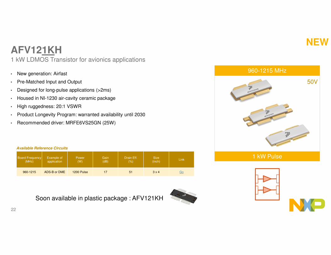
AFV121KH1 kW LDMOS Transistor for avionics applications
• New generation: Airfast
• Pre-Matched Input and Output
• Designed for long-pulse applications (>2ms)
• Housed in NI-1230 air-cavity ceramic package
• High ruggedness: 20:1 VSWR
• Product Longevity Program: warranted availability until 2030
• Recommended driver: MRFE6VS25GN (25W)
Available Reference Circuits
Board Frequency(MHz)
Example of application
Power (W)
Gain(dB)
Drain Eff. (%)
Size (inch)
Link
960-1215 ADS-B or DME 1200 Pulse 17 51 3 x 4 Go
960-1215 MHz
1 kW Pulse
50V
NEW
Soon available in plastic package : AFV121KH

23
AFV121KH Wideband Performance
20
30
40
50
60
70
80
0
200
400
600
800
1000
1200
1400
1600
900
910
920
930
940
950
960
970
980
990
100
0
101
0
102
0
103
0
104
0
105
0
106
0
107
0
108
0
109
0
110
0
111
0
112
0
113
0
114
0
115
0
116
0
117
0
118
0
119
0
120
0
121
0
121
5
122
0
123
0
124
0
125
0
126
0
127
0
128
0
129
0
130
0
Frequency MHz)
Pout@Pin=25W Eff@Pin=25W
Fixed Pin=25W, Pulse 128µs, 5% duty cycle, Vd=50V, Vg=2.19V, Idq = 100mA
In NXP wideband 960-1215 MHz reference circuit
1030 MHz Pout Gain Eff
P1dB 1355 17.8 53.0%
P2dB 1480 16.8 53.7%
Output Power
Eff.
Efficiency(%)
Pout(W)
Roadmap

24
-20%
-10%
0%
10%
20%
30%
40%
50%
60%
0
2
4
6
8
10
12
14
16
18
20
0 5 10 15 20 25 30 35 40 45
Pin (dBm)
Gain (db)
Efficiency(%)
Pout(W)
AFV121KH Narrowband performance
Eff.
Gain
Pout
1030 MHz, Pulse 120µs, 5% duty cycle, Vd=50V, Vg=2.02V, Idq = 100mA
In NXP preliminary narrowband 1030 MHz circuit
1030 MHz Pout Gain Eff
P1dB 1430 17.2 49%
P2dB 1625 16.2 51%
Roadmap

25
AFV121KH Planar Balun Circuit – Design in Progress
Roadmap
26
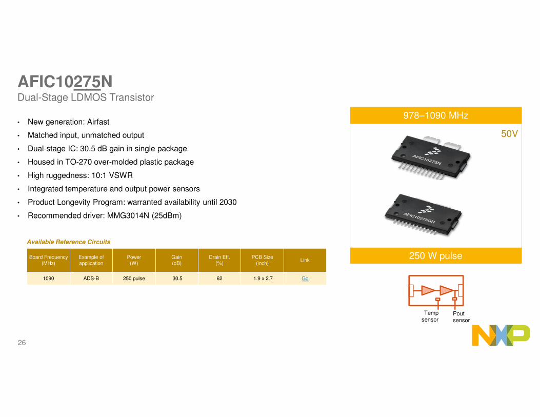
AFIC10275NDual-Stage LDMOS Transistor
• New generation: Airfast
• Matched input, unmatched output
• Dual-stage IC: 30.5 dB gain in single package
• Housed in TO-270 over-molded plastic package
• High ruggedness: 10:1 VSWR
• Integrated temperature and output power sensors
• Product Longevity Program: warranted availability until 2030
• Recommended driver: MMG3014N (25dBm)
Available Reference Circuits
Board Frequency(MHz)
Example of application
Power (W)
Gain(dB)
Drain Eff. (%)
PCB Size (inch)
Link
1090 ADS-B 250 pulse 30.5 62 1.9 x 2.7 Go
978–1090 MHz
250 W pulse
50V
Pout sensor
Temp sensor

27
AFIC10275N 250W @ 1090 MHz
•Frequency: 1090 MHz
•Functional performance @ 50V:•Power = 250 W
•Gain = 30.5 dB•Efficiency = 62 %
Size: 1.9 x 2.7" (4.8 x 6.9 cm)
1090 MHzPulse period=1280µs,
Pulse width=128µs (10% duty cycle), Vd=50V, Vg=5.2V, Id2q=150mA
Roadmap

28
Proposed Line-up for Air Traffic ControlLine-up for 250W 1090 MHz transponder:
Line-up for 500W 1090 MHz transponder :
Line-up for 1kW DME or ADS-B interrogator:
Driver+final stage: AFIC10275N
Pre-driver:MMG3014N (25 dBm)
3 mW (5dBm)
250 mW (24 dBm)
+19dB +30 dB
250 W (54 dBm)
Final stage: MRF6V12500H
Driver:MRF6V10010N (10W)
Pre-driver:MMG38151B (18dBm)
0.2 mW (-7 dBm)
120 mW (11 dBm)
5 W(37 dBm)
500W(57dBm)
+19dB +26dB +20 dB
Final stage: AFV121KH
Driver:MRFE6VS25GN (25W)
Pre-driver:MMG3005N (30dBm)
9 mW (9.4 dBm)
550 mW (27.5 dBm)
22 W(43.4 dBm)
1.1 kW(60.4 dBm)
+18dB +16 dB +17 dB

29
Proposed Line-up for RadarsLine-up for 300W L-band:
Line-up for 1kW L-band:
Line-up for 300W S-band:
Final stage: AFV141KH
Driver:MRFE6VS25N (25W)
Pre-driver:MMG3004N (27dBm)
6mW (8dBm)
300mW (25dBm)
12.5W(41dBm)
1KW(60dBm)
+17dB +16dB +19dB
Final stage: MRF6V14300H
Driver:MRFE6VS25N (25W)
Pre-driver:MMG3014N (25 dBm)
3mW (5.3 dBm)
270 mW (24.3 dBm)
5 W(37.3 dBm)
300 W(54.8 dBm)
+19 dB +13 dB +17.5 dB
Final stage: MRF8P29300H
Driver:A2I25D025N (25W)
15W(41.8 dBm)
300W(54.8dBm)
+13dB+30dB
15 mW(11.8 dBm)

30
RF POWER FOR MOBILE RADIO

31
7W
15W
50W
3W
Available Now
75W AFT05MP075N
31W 764-941 MHz
31W to 520 MHz
55W 764-941MHz
7W to 941
AFT09MP055N
AFT09MS015N
AFT09MS007N
AFT05MS031N
AFT09MS031N
All watts are CW.
P1dB
6W to 941 MHz
75W to 520
15W 136–941 MHz
4W to 941 MHz
AFT05MS006N
AFT05MS004N
3W to 941 MHz
12V LDMOS rugged
Plastic
7.2V LDMOS rugged
50V GaN
2016
1W to 941 MHz dual-stage ICAFIC901N
AFG24S100H
100 to 2400 MHz 100W
AFT05MS003N
6W to 941 MHz, DFN package
AFM906N
Mobile Radio
MRFE6S9060N 60W 470 to 960 MHz
2017
25W GaN
Execution
Production
Proposal
Right edge= Qualification date
Planning
28V LDMOS

32
AFIC901N1 W Frequency-Configurable LDMOS RFIC
Two-stage LDMOS Driver
• External interstage matching allows optimization
for range of voltages and frequencies
• 1W output power
• No driver needed: 0dBm input (30dB gain)
• Housed in a QFN 4 x 4 package
• Extreme Ruggedness: 65:1 VSWR
• Product Longevity program: warranted availability until 2030
Available Reference Circuits
Board Frequency(MHz)
Power (W)
Gain(dB)
Drain Eff. (%)
PCB Size Link
136-175 1 CW 30.6 62.1
0.83 x 1.88”
Go
350-520 1 CW 27.4 61.5 Go
760 – 870 1 CW 27.6 57.0
1.8-1000 MHz
1 W CW
7.5V
Same PCB used for all reference circuits
NEW

33
AFM906N
• Unmatched Input and Output
• Same performance as AFT05MS006N
• Housed in an DFN 4x6 over-molded plastic package
• Extreme Ruggedness: >65:1 VSWR
136-941 MHz
6 W CW (P1dB @ 7.5V)
7.5V
Planned Reference Circuit
Board Frequency(MHz)
Power (W)
Gain(dB)
Drain Eff. (%)
Size (inch)
135-175 6 CW 14 60 0.83 x 1.86
Q3 2016

34
AFT05MS003N
• Unmatched Input and Output LDMOS transistor
• Housed in an SOT89 over-molded plastic package
• Extreme Ruggedness: handles >65:1 VSWR
Available Reference Circuits
Board Frequency(MHz)
Power (W)
Gain(dB)
Drain Eff. (%)
PCB Size Link
136-175 3.4 CW 17.3 67.3 0.83 x 1.86” Go
350-520 3.4 CW 15.3 75.4 0.83 x 1.86” Go
1.8-941 MHz
3 W CW
7.5V
NEW

35
Possible Line-up for Mobile RadioLine-up for handheld radio:
Line-up for mobile (vehicle) radio:
Line-up for BTS:
Final stage:AFT05MS031N
Pre-driver:MMG3014N
6mW (8dBm)
620mW (28dBm)
+20dB +17dB
31W (45dBm)
Final stage:AFT05MP075N
Pre-driver:AFT05MS004N
50mW (17dBm)
2.4W (34dBm)
+17dB +15dB
75W (49dBm)
Final stage:AFT05MS004N
Pre-driver:MMG3014N
0.3mW (-5dBm)
20mW (13dBm)
+18dB +17dB

36
RF POWER FOR COOKING

37
NXP RF Cooking Component Trend
1 0.68 0.60 0.28
45% Eff190W
58% Eff250W
63% Eff250W
63% Eff250W
Normalized Price
Attributes
2012 2014 20172015

38
Production MW Heating Device Devices
Available Now
50W
250W
MHT2000N
MHT1001H
MHT1000H
140W, 45% eff
25W driver IC
190W, 45% eff
250W, 58% eff
MHT1007H1: Discrete2: IC
3. System
H: ceramicN: plastic
MHT1003N
10W driver
MHT1006N
MMG3014N
< 1W driver
28-32 V
Plastic
3.6-7.5V
Part Number Description Power PAE Gain Package
MHT1004 Final 300W 63% 15dB OM780
MHT1003 Final 250W 58% 15dB OM780
MHE1003 Final 220W 63% 15dB OM780
MHT1001 Final 190W 46% 13.2dB NI1230
MHT1000 Final 140W 45% 13.2dB NI880
MHT2000 Driver 20W 44% 27.7dB TO270
MHT1006 Driver 10W 55% 17dB PLD 1.5
MHT1008 Driver 12W 55% 17dB PLD 1.5
MMG3014 Pre-Driver 1W -- 16dB SOT12W driver
MHT1008N
NEW
MHE1003N
220W, 63% eff NEW
MHT1004NNEW
2.4GHz Band

39
RF Cooking Module Design Philosophy and Objective
• Modular Scalability
− Easily scale system ouput power from 250W to 1000W
− Design circuit for future re-use to scale power, number of channels, other features
• High Volume Manufacturable
− Designed for high throughput manufacturing
− Consumer cost structure
• Integration
− Enable smallest size
− Fit within appliance control and communications structure
− Enable circuit to silicon integration
H2 2016
40
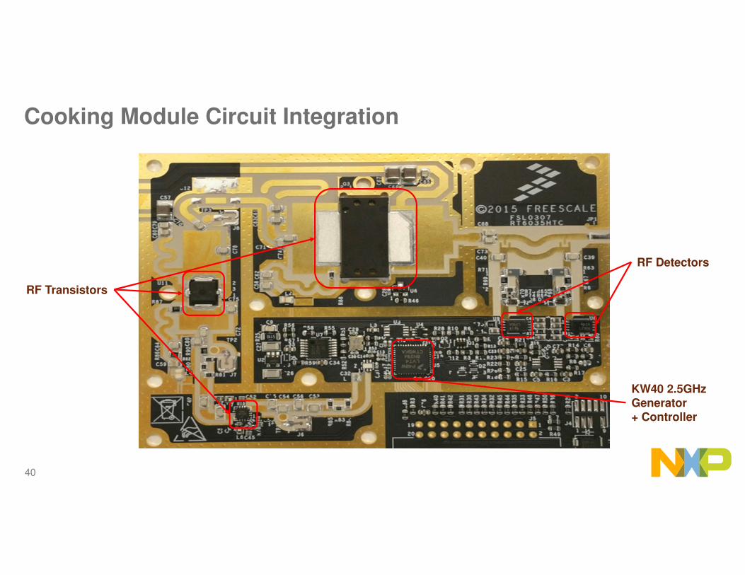
Cooking Module Circuit Integration
KW40 2.5GHz Generator+ Controller
RF Detectors
RF Transistors

41
SAGEIntelligent Cooking Appliance Reference Design
✓Smart, adaptive cooking device
✓Delivers consistent culinary excellence
✓Enhances convenience
✓Enables advanced apps and services, real-time customer insight

42
RF POWER FOR MILITARY

43
RF Military Business• Military is a separate business within NXP RF
• Enables focus on Military market and customers
• Specialized, dedicated support for defense applications
− Enable our existing RF technologies for this market
• Focus applications: Communications, Radar, Jammers/EW
Military Part Numbering (MMRF series)• Enables tracking of Military business
• Targets support by dedicated Mil Mkt/Apps/Systems team
• Data Sheet specs/features, Applications fixtures, Data packs targeted and optimized for Military end uses
• Longevity guarantee of 10 or 15 years for all Military (MMRF) devices
• Ensures proper compliance processes when needed (e.g. non EAR99 parts)
• Hides frequency & power information (customers like)
NXP RF Military EMEA Engagement Model
For more info, ask your local sales

44
RF POWER FOR CELLULAR
45
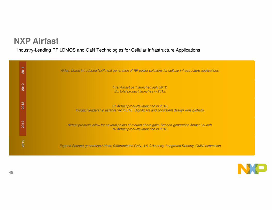
NXP AirfastIndustry-Leading RF LDMOS and GaN Technologies for Cellular Infrastructure Applications
Airfast brand introduced NXP next generation of RF power solutions for cellular infrastructure applications.
First Airfast part launched July 2012.Six total product launches in 2012.
21 Airfast products launched in 2013.Product leadership established in LTE. Significant and consistent design wins globally.
Airfast products allow for several points of market share gain. Second-generation Airfast Launch.16 Airfast products launched in 2013.
2011
2012
2013
2014
Expand Second-generation Airfast, Differentiated GaN, 3.5 GHz entry, Integrated Doherty, OMNI expansion2015
46
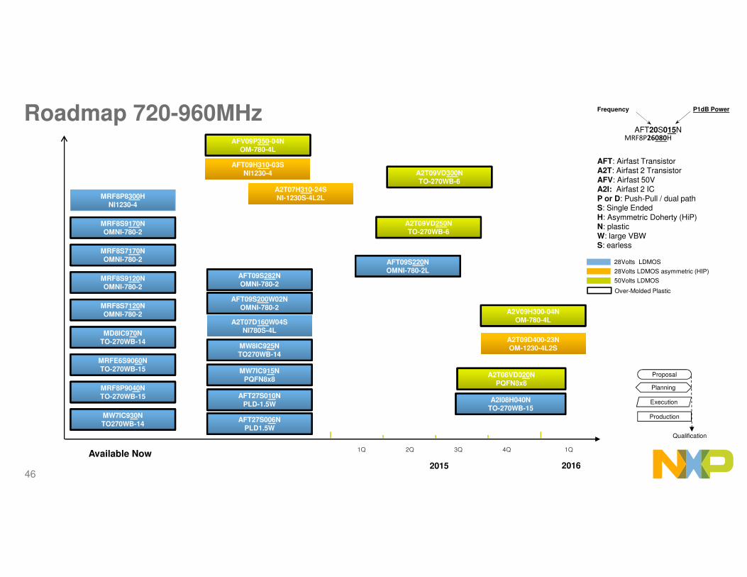
Roadmap 720-960MHz
2015
2Q 3Q 4Q1Q
AFV09P350-04NOM-780-4L
MRF8P8300HNI1230-4
AFT09H310-03SNI1230-4
AFT09H310-03SNI1230-4
AFT09S282NOMNI-780-2
MRF8P9040NTO-270WB-15
MRFE6S9060NTO-270WB-15
MD8IC970NTO-270WB-14
MRF8S7120NOMNI-780-2
MRF8S7170NOMNI-780-2
MRF8S9120NOMNI-780-2
MRF8S9170NOMNI-780-2
Available Now
28Volts LDMOS
28Volts LDMOS asymmetric (HIP)
Over-Molded Plastic
AFT: Airfast TransistorA2T: Airfast 2 Transistor
AFV: Airfast 50VA2I: Airfast 2 IC
P or D: Push-Pull / dual pathS: Single Ended
H: Asymmetric Doherty (HiP)N: plastic
W: large VBWS: earless
Execution
Production
Proposal
Qualification
Planning
AFT20S015N
Frequency P1dB Power
MRF8P26080H
50Volts LDMOS
AFT09S200W02NOMNI-780-2
A2T07D160W04SNI780S-4L
A2T07D160W04SNI780S-4L
A2T07H310-24SNI-1230S-4L2LA2T07H310-24SNI-1230S-4L2L
MW7IC915NPQFN8x8
AFT27S006NPLD1.5W
AFT27S010NPLD-1.5W
A2T08VD020NPQFN8x8
A2T09VD250NTO-270WB-6
A2T09VD300NTO-270WB-6
MW7IC930NTO270WB-14
MW8IC925NTO270WB-14
AFT09S220NOMNI-780-2L
A2I08H040NTO-270WB-15
A2T09D400-23NOM-1230-4L2S
A2T09D400-23NOM-1230-4L2S
A2V09H300-04NOM-780-4L
1Q
2016

47
Roadmaps Discrete 1.8/1.9 GHz
2015
MRF8P20165WHNI780-4
MRF8P19260HNI1230-4
MRF7P20040HNI780-4
AFT18P350-4S2LNI1230-4L2L
AFT18S230SNI780-6
AFT18HW355SNI1230-4
AFT20P140-4WNOM780-4
AFT18S290-13SNI−880XS−2L4S
AFT20P060-4NOM780-4
AFT18S160W02SNI-780-2
MRF8P20100HNI780-4
Available Now 3Q 4Q2Q
A2T18H100-25SNI780-4L4S
AFT18H357-24SNI1230-4L2L
28Volts LDMOS discrete/IC
28Volts LDMOS HiP
Over-Molded Plastic
AFT: Airfast TransistorA2T: Airfast 2 Transistor
A2I: Airfast 2 ICP or D: Push-Pull / dual path
S: Single EndedH: Asymmetric Doherty (HiP)
N: plasticW: large VBW
S: earless
Execution
Production
Proposal
Qualification
Planning
AFT20S015N
Frequency P1dB Power
MRF8P26080H
AFT27S010NTO270-2
AFT27S006NTO270-2
AFT20S015NTO270-2
A2T18H450W19SNI-1230-4S4S
A2T20H330W24SNI-1230-4L2L
A2T18H160-24SNI-780-4L2L
A2T18H410-24SNI-1230-4L2L
1Q
AFT18H357-3NOM1230-4L2L
A2T18S260W12NOM880X-2L2L
2016
1Q
A2T20H160W04NOM-780-4L

48
2Q 3Q 4Q1Q
A2I20H060NTO-270WB-15
A2I25D025NTO-270WB-15
MD7IC2050NTO270WB-14
MW7IC2020NPQFN 8x8
MW7IC2040NTO270WB-14
MD7IC2012NTO270WB-14
Roadmaps ICs 1.8/1.9 GHz
2015
28Volts LDMOS discrete/IC
28Volts LDMOS HiP
Over-Molded Plastic
AFT: Airfast TransistorA2T: Airfast 2 Transistor
A2I: Airfast 2 ICP or D: Push-Pull / dual path
S: Single EndedH: Asymmetric Doherty (HiP)
N: plasticW: large VBW
S: earless
Execution
Production
Proposal
Qualification
Planning
AFT20S015N
Frequency P1dB Power
MRF8P26080H
MD7IC1812NTO-270WB-14
A2I20D040NTO-270WB-17
2016
1Q 2Q

49
Roadmaps Discretes 2.1 GHz
MRF8HP21080HSNI780-4
MRF8S21172HSNI780-2
AFT21H350W03SNI1230-4S
AFT21S232SNI780-2
AFT21S230SNI780-6
AFT20P060-4NOM780-4
Available Now
2015
A2T21H100-25SNI-780-4L4S
28Volts LDMOS discrete/IC
28Volts LDMOS HiP
Over-Molded Plastic
AFT: Airfast TransistorA2T: Airfast 2 Transistor
A2I: Airfast 2 ICP or D: Push-Pull / dual path
S: Single EndedH: Asymmetric Doherty (HiP)
N: plasticW: large VBW
S: earless
Execution
Production
Proposal
Qualification
Planning
AFT20S015N
Frequency P1dB Power
MRF8P26080H
AFT27S010NTO270-2
AFT27S006NTO270-2
AFT20S015NTO270-2
AFT21S240-12SNI-880XS-2L2L
AFT21S220W02SNI-780S-2L
2Q 3Q 4Q1Q
A2T21H360-24SNI-1230-4L2L
A2T21H450W19SNI-1230S-4S4S
A2T21S160-12SNI-780S-2L2L
A2T21S260-12SNI-780S-2L2L
A2T21S180-13SNI-780S-2L4S
A2T21H410-24SNI-1230S-4L2L

50
2Q 3Q 4Q1Q
A2I22D050NTO-270WB-15
MW7IC2240NTO270WB-16
MD7IC2250GNTO270WB-14
MW7IC2220NTO270WB-16
MW7IC2020NPQFN 8x8
MD7IC21100NTO270WB-14
MD7IC2012NTO-270WB-14
2015
Asymmetric Doherty Devicesin Plastic
28Volts LDMOS discrete/IC
28Volts LDMOS HiP
Over-Molded Plastic
AFT: Airfast TransistorA2T: Airfast 2 Transistor
A2I: Airfast 2 ICP or D: Push-Pull / dual path
S: Single EndedH: Asymmetric Doherty (HiP)
N: plasticW: large VBW
S: earless
Execution
Production
Proposal
Qualification
Planning
AFT20S015N
Frequency P1dB Power
MRF8P26080H
Roadmaps ICs 2.1 GHz

51
Roadmaps 2.3 GHz
Discrete
Integrated
circuits
MRF8P23080HSNI780-4
AFT23S160W02SNI780-2L
AFT23S170-13SNI780-2L4S
AFT27S010NTO270-2
AFT23H200-4S2LNI1230-4L2L
AFT27S006NTO270-2
AFT23S160-13SNI780-2S
AFT20S015NTO270-2
Execution
Production
Proposal
Qualification
Planning
2015
2Q 3Q 4Q1Q
MD7IC2755NTO270WB-14
MW7IC2725NTO270WB-16
A2I25D012NTO270WB-14
TO-270WB-15A2I25D025N
TO-270WB-15
Available Now
Asymmetric Doherty ICs
28Volts LDMOS discrete/IC
28Volts LDMOS HiP
Over-Molded Plastic
AFT: Airfast TransistorA2T: Airfast 2 Transistor
A2I: Airfast 2 ICP or D: Push-Pull / dual path
S: Single EndedH: Asymmetric Doherty (HiP)
N: plasticW: large VBW
S: earless
AFT20S015N
Frequency P1dB Power
MRF8P26080H
AFT23H160-24SNI-780S-4L2L
A2T23H160-24SNI-780S-4L2L
A2T23H300-24SNI-1230S-4L2L

52
Roadmaps 2.6 GHz
2015
A2I25D025NTO-270WB-15
Available Now 2Q 3Q 4Q1Q
Execution
Production
Proposal
Qualification
Planning
28Volts LDMOS discrete/IC
28Volts LDMOS HiP
Over-Molded Plastic
AFT: Airfast TransistorA2T: Airfast 2 Transistor
A2I: Airfast 2 ICP or D: Push-Pull / dual path
S: Single EndedH: Asymmetric Doherty (HiP)
N: plasticW: large VBW
S: earless
AFT20S015N
Frequency P1dB Power
MRF8P26080H
A2I25H060NTO270WB-17
A2T26H160-24SNI-780-4L2L
MRF8P26080HSNI780-4
MD7IC2755NTO270WB-14
MW7IC2725NTO270WB-16
AFT26H200W03S/-24S NI1230-4S/4L2L
AFT27S006NPLD1.5W
AFT20S015NTO270-2
AFT27S010NPLD1.5W
AFT26HW050SNI780-4S4
AFT26P100-4WSNI780-4S
AFT26H250-24SNI1230-4L2L
A2I25D012NTO270WB-15
A2T26H300-24SNI-1230S-4L2L
A2T26H165-24SNI-780S-4L2L
Discrete
Integrated
circuits

53
Roadmaps GaN
Discrete
Drivers
2015
2Q 3Q 4Q1Q
Execution
Production
Proposal
Qualification
Planning
50V GaN
AFT: Airfast TransistorA2T: Airfast 2 Transistor
A2I: Airfast 2 ICP or D: Push-Pull / dual path
S: Single EndedH: Asymmetric Doherty (HiP)
N: plasticW: large VBW
S: earless
AFT20S015N
Frequency P1dB Power
MRF8P26080H
A2G22S160-01SNI400
10W
100W
1.8-2.2 GHz
2.3-2.7 GHz
2.3-2.7 GHz
A2G22S250-01SNI400
2016
2Q1Q
A2G26H280-04SNI-780S-4L
