eurocell conservatory roof systema-windows.co.uk/eurocell_roof_installation_guide.pdf ·...
TRANSCRIPT

Eurocell Conservatory Roof System
Installation ManualIssue 2 / January 2008

Installation ManualIssue 2 / January 2008
Index
Contents
Statement
General Assemblies – Cross Sections
Victorian/ Edwardian Roof Installation
Jack Rafter Installation
P Shape Roof Installation
15-45 Lean To Installation
2.2-15 Lean To Installation
Box Gutter Installation
Raised Box Gutter/Guttering Installation
Gable Fronted Roof Installation
Half Spider Situation
Tie Bar Installation
Bolster Bar Installation
Updates
Section No.
1
2
3
4
5
6
7
8
9
10
11
12
13
14

Installation ManualIssue 2 / January 2008
Section 1: Statement
Section 1:1
Statement
All the information in this Installation Manual is provided for guidance only and is given in good faith, but without warranty or guarantee of any kind, whether implied or expressed. It must be understood that Eurocell has no control over how the information in this document is interpreted and therefore cannot be held responsible for any resulting fabrication or product failure, howsoever caused.
Statutory regulations regarding health and safety of operative’s personnel should be strictly adhered to. Eurocell cannot be held responsible for any failure to comply with them. This statement does not affect your statutory rights.
Eurocells policy is to continually improve products, therefore methods, materials and changes of specification may be made from time to time without prior notice.
Updating of Product Manual
To ensure that the Product Manual is kept up to date all registered holders of the said manual will be supplied with current amendments immediately upon their release.
It is the responsibility of the appointed holder of the manual to ensure that the information supplied is correctly inserted into the manual and acceptance returned.
For any further information or conformation regarding the current issue of the Eurocell Technical Publication, please contact the Eurocell Technical Department.

Installation ManualIssue 2 / January 2008
Section 1: Statement
Section 1:2
Roof Anatomy

Installation ManualIssue 2 / January 2008
Section 2: General Assemblies – Cross Sections
Section 2:1
Rafter Assemblies
RAFTERASSEMBLY
EDWARDIANASSEMBLY
VICTORIANASSEMBLY
LIGHTWEIGHTRAFTER
ASSEMBLY
GABLE RAFTERASSEMBLY
GABLE RAFTERASSEMBLY
(AGAINST WALL)
CRS8016
CRS8501A
CRS8011
CRS8011
CRS8502A
CRS8017
CRS8012
CRS8018
CRS8503A
CRS8012
CRS8011
CRS8016
CRS8500A
CRS8019
CRS8504A CRS8504A
CRS8019CRS8015
CRS8014
CRS8011

Installation ManualIssue 2 / January 2008
Section 2: General Assemblies – Cross Sections
Section 2:2
Rafter Assemblies (Aluminium Top Caps)
RAFTERASSEMBLY
EDWARDIANASSEMBLY
VICTORIANASSEMBLY
LIGHTWEIGHTRAFTER
ASSEMBLY
GABLE RAFTERASSEMBLY
GABLE RAFTERASSEMBLY
(AGAINST WALL)
CRS8501A
CRS8011
CRS8011
CRS8502A
CRS8012
CRS8517A
CRS8518A
CRS8503A
CRS8012 CRS8011
CRS8500A
CRS8519A
CRS8504A CRS8504A
CRS8519ACRS8015
CRS8014
CRS8011
CRS8516A
CRS8516A

Installation ManualIssue 2 / January 2008
Section 2: General Assemblies – Cross Sections
Section 2:3
Ring Beam & Valley Assemblies
CRS8207
CRS8053
CRS8551A
CRS8059CRS8051
CRS8553A
RING BEAMASSEMBLY
RING BEAMASSEMBLY WITH
INTEGRAL GUTTER
VALLEY ASSEMBLY
CRS8050
CRS8551A
CRS8059
CRS8553A
EWS8543AEWS8544A
CRS8041
CRS8042
RWK G4

Installation ManualIssue 2 / January 2008
Section 2: General Assemblies – Cross Sections
Section 2:4
Ridge Assemblies
RIDGE ASSEMBLY
FIXED PITCHRIDGE ASSEMBLY
CRS8021
CRS8525A
CRS8028
CRS8069
CRS8521A
CRS8021
CRS8028CRS8520A
CRS8069

Installation ManualIssue 2 / January 2008
Section 2: General Assemblies – Cross Sections
Section 2:5
Wall Plate Assemblies
LEAN TO ASSEMBLY
WALL PLATE ASSEMBLY
CRS 8580A
CRS 8081
CRS 8582A
CRS 8069
CRS 8028
CRS 8525ACRS 8522A
CRS 8024
CRS 8021
CRS 8080
CRS 8480

Installation ManualIssue 2 / January 2008
Section 2: General Assemblies – Cross Sections
Section 2:6
Box Gutter Assemblies
CRS8053
CRS8551A
CRS8059
CRS8553A
BOX GUTTERASSEMBLY
INTEGRAL BOXGUTTER ASSEMBLY
CRS8050
CRS8551A
CRS8059
CRS8553A
CRS8552A
UB275
CRS8458
CRS8058
CRS8554A
UB225
CRS8054
Installation ManualIssue 2 / January 2008
Section 2: General Assemblies – Cross Sections
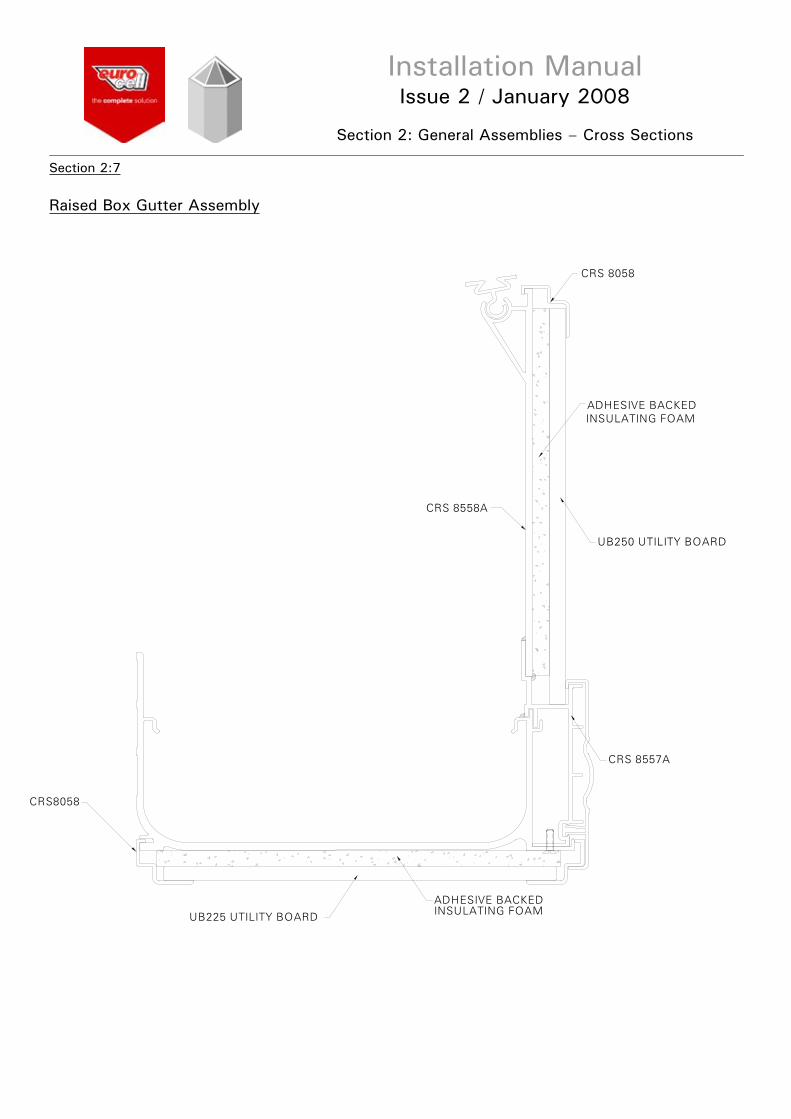
Section 2:7
Raised Box Gutter Assembly
ADHESIVE BACKEDINSULATING FOAM
UB250 UTILITY BOARD
UB225 UTILITY BOARD
CRS8058
ADHESIVE BACKEDINSULATING FOAM
CRS 8557A
CRS 8058
CRS 8558A

Installation ManualIssue 2 / January 2008
Section 3: Victorian/Edwardian Roof Installation
Section 3:1
2) Join remaining sections of Ring Beam together using both the Pressed and Flat Steel Cleats.
3) Fix the Ring Beam to the Window Frames from the inside ofthe windows through into the RingBeam using 4.8dia. self-tapping screws at a maximum of 600mm between fixings.
4) Hook into position on the Ring Beam the Ring Beam Variable Support. Slide the appropriate number of double studs (for the rafter) and Single Studs (for the Hips and Gable Rafter) down the Ring Beam Variable Support. NOTE: The studs must be fitted to EACH individual Ring Beam Variable Support as they are fitted.
1) Fit the first section of Ring Beam into position ensuring its correct location. Remember to fit the External Trim before positioning (or Integral gutter if used).
5) Whilst at floor level, ensure the Ridge Variable Support and the Ridge Glazing Trim has been positioned within the Ridge, and that the Nylon Threaded Bar has been fitted to the Spider Bracket. Slide the appropriate number of Double studs down the Ridge Variable Support for Rafter and Single studs for Gable Rafter.
6) Raise the assembled Ridge up to its correct height and temporarily support. Loosely fit the Gable Rafters complete with Wall Rafter Gutter to the Ridge and Ring Beam.
7) Fix the Hips complete with Spider Bar Moulding on to the Spider Bar. Fix the Hips onto the Ring Beam using Single Studs. Align the centre line of the Hips with the center of the Spider Bar. Once aligned, tighten the Grub Screws.
Wall RafterGutter
RidgeVariableSupport
RidgeGlazing Trim

Installation ManualIssue 2 / January 2008
Section 3: Victorian/Edwardian Roof Installation
Section 3:2
9) Fix the Gable Rafters to the Wall using appropriate fixings. 3 Places per Rafter.
10) Cut to length and fit the EavesBeam Seal into the Ring Beam Variable Support. DO NOT removeprotective tape at this time. (This may have been performed byyour supplier).
11) Carry out the Lead Flashing. The method and style of this is left to the installer although the flashing should finish inside the Wall Rafter Gutter. DO NOT flash around the Ridge at this point.
12) Fit a Glazing Stop and End Cap (Rafter/ Hip or Gable Rafter) to each Glazing Bar.
13) Fit the Glazing End Trim to theGlazing. If using Polycarbonate, peel back the protective film to enable the fitting of the End Trim. Seal End Trim using a suitable silicone sealant.
14) The order of Glazing should bedone in a specific way. Panels that sit on a Hip should be done first. So in the example shown, glaze panels 1 to 5 or 1 to 8 before glazing any others.
15) To Glaze, slide the Glazing panel on to the Rafters/ Hips and slide into the Ridge Glazing Trim if applicable (Remember to remove protective film if using polycarbonate).
16) Remove the protective tape from the Eaves Beam Seal, pull back the Glazing Sheet to the Glazing Stop and seat onto the Seal. Pull back tape film 1-2 inches and fold to inside of conservatory. Position glazing ensuring it is sealed down on glazing stops. Peal away tape film and pat glazing down from outside.
17) Once the Glazing is in positionthe Hip Top Caps can be fitted, making sure they butt unto the Ridge End Sealing Assembly.
1
23
4
5 1
4 5
8
23 6
7
Ensure lead finishes inside the Wall RafterGutter
32
24/2
5
Installation ManualIssue 2 / January 2008
Section 3: Victorian/Edwardian Roof Installation
Section 3:3
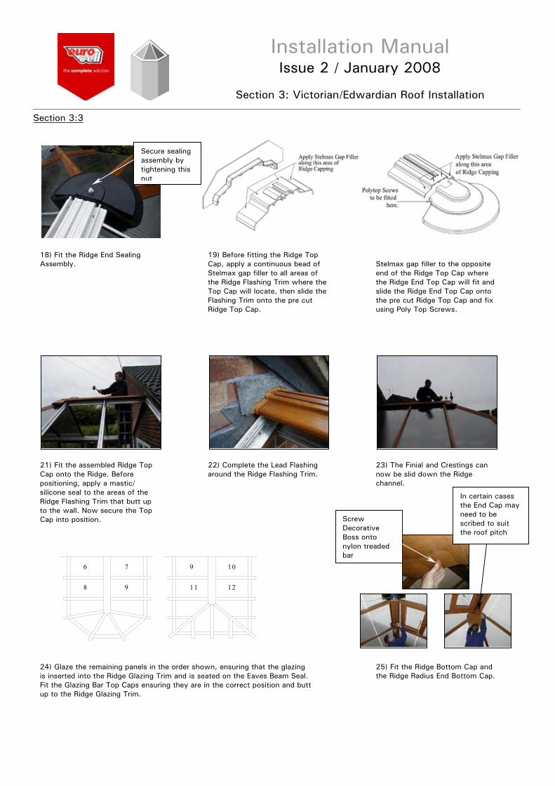
18) Fit the Ridge End Sealing Assembly.
19) Before fitting the Ridge Top Cap, apply a continuous bead of Stelmax gap filler to all areas of the Ridge Flashing Trim where the Top Cap will locate, then slide the Flashing Trim onto the pre cut Ridge Top Cap.
20) Apply a continuous bead of Stelmax gap filler to the opposite end of the Ridge Top Cap where the Ridge End Top Cap will fit and slide the Ridge End Top Cap onto the pre cut Ridge Top Cap and fix using Poly Top Screws.
21) Fit the assembled Ridge Top Cap onto the Ridge. Before positioning, apply a mastic/ silicone seal to the areas of the Ridge Flashing Trim that butt up to the wall. Now secure the Top Cap into position.
22) Complete the Lead Flashing around the Ridge Flashing Trim.
23) The Finial and Crestings can now be slid down the Ridge channel.
24) Glaze the remaining panels in the order shown, ensuring that the glazing is inserted into the Ridge Glazing Trim and is seated on the Eaves Beam Seal. Fit the Glazing Bar Top Caps ensuring they are in the correct position and buttup to the Ridge Glazing Trim.
25) Fit the Ridge Bottom Cap and the Ridge Radius End Bottom Cap.
121198
6 7 9 10
Secure sealing assembly by tightening this nut
ScrewDecorativeBoss onto nylon treaded bar
In certain cases the End Cap may need to be scribed to suit the roof pitch

Installation ManualIssue 2 / January 2008
Section 3: Victorian/Edwardian Roof Installation
Section 3:4
26) Fit the Internal Ring Beam Trims to the Ring Beam.
27) Apply glue to ONE inside face of the Ring Beam Joint Trim.
28) Fit the Trim to the Joint between the two Ring Beam Internal Trims. Repeat this process for all other Joints.
Installation ManualIssue 2 / January 2008
Section 4: Jack Rafter Installation
Section 4:1
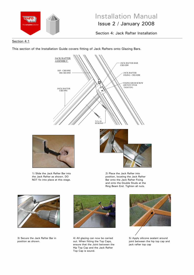
This section of the Installation Guide covers fitting of Jack Rafters onto Glazing Bars.
1) Slide the Jack Rafter Bar into the Jack Rafter as shown. DO NOT fix into place at this stage.
2) Place the Jack Rafter into position, locating the Jack Rafter Bar onto the Jack Rafter Fixing and onto the Double Studs at the Ring Beam End. Tighten all nuts.
3) Secure the Jack Rafter Bar in position as shown.
4) All glazing can now be carried out. When fitting the Top Caps, ensure that the Joint between the Hip Top Cap and the Jack Rafter Top Cap is sound.
5) Apply silicone sealant around joint between the hip top cap and jack rafter top cap

Installation ManualIssue 2 / January 2008
Section 5: P Shape Roof Installation
Section 5:1
This section of the Installation Guide covers the installation procedures for the following: 1) P Shape style Conservatory Roof
2) Valley
1) Before the installation of the roof commences, fit the fixing cleats to the Wall Plate as shown. It is not necessary to locate the screws through the holes in cleats.
3) Move the Wall Plate into position and fix the back to the wall at a maximum of 600mm centres. Now fix the Ridge to the fixing cleats previously fitted on the Wall Plate.
2) Fit the Wall Plate Variable Support complete with Glazing Trim to the Wall Plate. Slide a Single Stud (for Valley) and Double Studs down the Variable Support for the Glazing Bars.
4) Before fitting of the Valley commences, ensure that the Valley Double Sided Tape has been fitted in the position shown on both wings of the Valley. (Do Not remove the backing tape at this time).
5) Position and fix the first wing of the Valley ensuring the connecting lug is facing upwards. Do Not fully tighten the nuts at this stage.
6) Now fit the other wing of the Valley ensuring that the assembly is in the centre of both the Ridge/ Wall Plate and Ring Beam.
W all P late
R idge G lazing Trim
W all P lateVariable Support
lug is facingupwards
Double Sided Tape

Installation ManualIssue 2 / January 2008
Section 5: P Shape Roof Installation
Section 5:2
7) Pull back tape film 1-2 inches and fold to inside of conservatory. Position glazing ensuring it is seated down on glazing stops. Peel away tape film and pat glazing down from outside.
8) When glazing around the Valley, always start at the top near the Ridge and work down, i.e. in the order 1 to 6 on the example shown.
9) On some occasions it may be necessary to glaze panels 1 and 2 before the Jack Rafters are fitted. In this situation push the Glazing into the Ridge Glazing Trim and slide into position. Bed down the glazing onto the Valley Double Sided Tape.
10) Slide a 30mm long M6 Bolt upthe channel in the Valley and secure the Jack Rafters into position at both ends. Fully tightenthe bolts at both ends of the Valley.
11) Fit the remaining Glazing Bars ready for Glazing.
12) When all Glazing is complete, the Glazing Bar Top Caps including the Valley Top and Bottom Caps can be fitted.
13) Once the Ridge and Wall Plate Top Caps have been fitted, the Ridge Top cap Corner Trim can be fitted. Apply Stelmax Gap Filler to the under side of the Corner Trim.
14) Locate the Corner Trim and fixusing Poly Top screws in the position shown. Remove any excess gap filler.
Push glazing into glazing trim and slide into position
Bed down the glazing onto the double-sided tape
If the Jack RafterBar has not been fitted refer to Section 2:1

Installation ManualIssue 2 / January 2008
Section 6: 15-45 Lean To Roof Installation
2) Fit the Ring Beam onto theWindow Frames as described earlier in this guide. Fit the Ring Beam Variable Support into the Ring Beam and slide sufficient Single and Double Studs down for the Glazing Bars.
4) Lift the Wall Plate assembly into position ensuring it is level both horizontally and vertically. Fix through the whole assembly into the wall. As shown opposite
Section 6:1
This Section of the Installation Guide contains guidelines for a 15-45 Lean To Conservatory. There are two methods of fixing the Wall Plate, which depends on the following information:
1) Wall Plate, Wall Plate Variable Support and Glazing Trim unassembled, use METHOD 1 2) Wall Plate, Wall Plate Variable Support and Glazing Trim pre-assembled at the correct angle, use METHOD 2
Method 1
Method 2
1) Support the Wall Plate in position. Once satisfied with its position, drill through the Wall Plate and into the host wall. Fix the Wall Plate into the wall using appropriate fixings. If required, use packing behind the Wall Plate if the wall is not even.
2) Fit the Wall Plate Variable Support complete with Glazing Trim to the Wall Plate. Slide sufficient Double and Single Studs into the Variable Support for the Glazing Bars.
3) Fit the Ring Beam onto the Window Frames as described earlier in this guide. Fit the Ring Beam Variable Support into the Ring Beam and slide sufficient Single and Double Studs down for the Glazing Bars.
4) Fix the Gable Rafters into position. (fix back towall if applicable, remembering to fit the Wall Rafter Gutter).
5) Fix remaining Rafters into position, checking all centres as you go.
6) Fix the Wall Plate Top Cap into position and Lead Flash as shown in the diagram above. The Wall Plate BottomCap can also be fitted at this stage. As shown opposite.
7) Cut and fit the Eaves Beam Seal into position. DO NOT remove protective tape at this time. END OF METHOD 1 Proceed to section 6:2
1) Lay the pre-assembled Wall Plate complete with sufficient Single and Double Studs on top of the Window Frames.
3) Fix the Gable Rafters into position.
5) Fix remaining Rafters into position, checking all centres as you go.
6) Fix the Wall Plate Top Cap into position and Lead Flash as shown in the diagram. TheWall Plate Bottom Cap can also be fitted at this stage.
7) Cut and fit the Eaves Beam Seal into position. DO NOT remove protective tape at this time. END OF METHOD 2

Installation ManualIssue 2 / January 2008
Section 6: 15-45 Lean To Roof Installation
Section 6:2
8) Fit the Glazing Stops and Glazing Bar End Caps as describedearlier in this guide.
9) Fit the Glazing End Trims to theGlazing, apply silicone along end trim before fitting. If using polycarbonate, peel back enough protective tape to allow fitting of the End Trims.
10) Slide the Glazing onto the Rafters and into the Ridge/Wall Plate Glazing Trims.
11) Remove the protective tape from the Eaves Beam Seal, pull down Glazing to the Glazing Stop and seat onto the Eaves Beam Seal. (If using polycarbonate, remove protective film).
12) Once the Glazing is in position, snap on the Glazing Bar Top Caps ensuring they are snapped into the correct position and that they are butted up to the Ridge Glazing Trim. Fold up and clip the Glazing Bar End Caps into position.
13) The Ring Beam End Cap can now be fitted. To fit the End Cap, first cut down the capping to suit the pitch of the roof as shown.
14) Apply a bead of neutral cure silicone to the areas of the End Cap that locate onto the Ring Beam. Then place into position.
15) Fit the Gable End Trim onto the Gable Rafters (If they are not adjacent to a wall).
16) Apply a bead of neutral cure silicone seal to the areas of the Half Ridge Gable End Cap that willsit on the Wall Plate Top Cap.
17) Position the Gable End Cap into its correct position.

Installation ManualIssue 2 / January 2008
Section 7: 2.5 -15 Lean To Roof Installation
Section 7:1
The installation of this style of conservatory roof is similar to that of the 15-45 style of roof
Any other installation information for the 2.5-15 Lean To style conservatory is the same as for the 15-45 roof with the exception of the Lean To End Caps. The Installation guidelines for these are as follows.
1) Support the Wall Plate in position. Drill through the Wall Plate into the host wall. Fix the Wall Plate to the wall using the appropriate fixings. (Use packing ifrequired).
2) Hook the Variable Support into position as shown and then fit the Ridge Glazing Trims. Slide sufficient Double Studs down the Variable Support for the Rafters (Not the Gable Rafters).
3) Fit the Ring Beam onto the window frames as described earlier and fit the Ring Beam Variable Support complete with enough Double Studs for the Rafters.
4) Attach the Gable Rafters to either the Window Frames, Infill Panel or Timber Framework.
5) Fix the Rafters into position checking the centres as you go.
6) Fit the Lean to Seal onto the Lean To Variable Support and Glazing Trim as shown. Then fit the Lean To Top Cap and carry out the Lead Flashing onto it. The Lean To Bottom Cap can also be fitted at this point.
7) Apply a bead of neutral cure silicone to the lip of the End Cap that sits onto the Lean To Top Cap. Then locate the End Caps into their correct position.
WALL PLATEVARIABLE SUPPORT
GLAZING TRIM

Installation ManualIssue 2 / January 2008
Section 8: Standard Guttering Installation
Section 8:1
1) The Box Gutter should rest on the Window Frames. Before positioning, apply a neutral cure silicone on all areas of the Window Frame where the Box Gutter will sit.
2) Before positioning, locate the Box Gutter Insulation Trim into position on the Box Gutter. The Box Gutter can then be raised into position.
3) Drill through the Box Gutter into the host wall. The Box Gutter can then be fixed to the wall using appropriate fixings at a maximum of 600mm centres.
4) Position and fix the Ring Beam complete with Variable Support to the Box Gutter at 600mm maximum centres. Ensuring that sufficient Double and Single Studs are positioned within the Variable Support.
5) Offer up and position the Box Gutter under Cladding. Whilst supporting, fit the Ring Beam Internal Trim. The Lead Flashing can now be fitted.
BOX GUTTER
FASCIA BOARD RETAINING TRIM
WINDOW FRAME
ALONG FRAMEAPPLY SILICONE
BOX GUTTER
3.9 x 16 SELF TAPPINGSCREW
RING BEAMVARIABLE SUPPORT
RING BEAM
BOX GUTTERUNDER CLADDING
ADHESIVE BACKEDINSULATING FOAM
LEAD FLASHING
INTERNAL TRIMRING BEAM
WALL ANCHOR

Installation ManualIssue 2 / January 2008
Section 9: Box Gutter Adaptor Installation/ Guttering Installation
Section 9:1
The Following is a guide on how to fit a box gutter adaptor.
Guttering Installation
It is assumed that the installer has knowledge of Guttering so only instructions specific to Eurocell components are given.
1) Before attempting to fit the adaptor, ensure that the inside edge of the Box Gutter is fully De-Burred.
2) Smear soapy water on the inside face of the Box Gutter where the Adaptor will locate and to the seal that is fitted on the Adaptor.
3) Push the Box Gutter Adaptor into position as shown.
4) Position the Box Gutter Brace inthe Groove on the adaptor with one part of the Brace hooked into position.
5) To fit the other section of the Box Gutter Brace, lower it into position and then apply pressure in the position shown to cause compression to enable the brace to be clipped into position.
6) To join the adaptor onto existing standard guttering, use a straight union.
1) Gutter Brackets must be fitted at a maximum of 600mm centres and no more than 200mm from each corner. The Gutter Brackets are located in the Ring Beam External Trim and are twisted into position as shown.
2) To clip the Guttering into position, clip the front part of the Gutter Bracket into the Gutter section.
3) Rotate the rear section of the Gutter up and clip into position.

Installation ManualIssue 2 / January 2008
Section 10: Gable Fronted Roof Installation
Section 10:1
On a Gable End style conservatory, both Internal and External Gable End Caps are required.
1) Apply a bead of neutral cure silicone to the areas of the pre-cut Ridge Top Cap that the External End Cap will fit.
2) Position the External End Cap inits correct location as shown.
3) The External Gable End Trim must be cut to the required roof pitch.
4) Slide the End Trim onto the Ridge Bottom Cap.
5) When installing, apply a neutral cure silicone or mastic seal onto the face of the trim that is against the Window Frames. Now fit Ridge Bottom Cap complete with End Trim.

Installation ManualIssue 2 / January 2008
Section 11: Half Spider Situation
Section 11:1
4) Fit the Gable Bar complete withGable Bar Moulding to the Half Spider Bracket, loosely fit the other end onto the Ring Beam using a Double Stud.
5) Fix the Gable Bar to the wall using appropriate fixings. 3 Places.
6) Fix the Hip(s) complete with Spider Bracket Mouldings to the Half Spider Bracket. Fix the Hip(s) onto the Ring Beam using Single Studs. Align the centreline of the Hips with the centreline of the Threaded Bar. Once aligned tighten Grub screws.
7) Fit a Glazing Stop and End Cap (Rafter/Hip or Gable Rafter) to each Glazing Bar.
8) Cut to length and fit the Eaves Beam Seal into the Ring Beam Variable Support. DO NOT removeprotective tape at this time.
9) Carry out the Lead Flashing. The method and style of this is left to the installer although the flashing should finish inside the Wall Rafter Gutter. DO NOT flash around the Ridge at this point.
Installation ManualIssue 2 / January 2008
Section 11: Half Spider Situation
Section 11:2
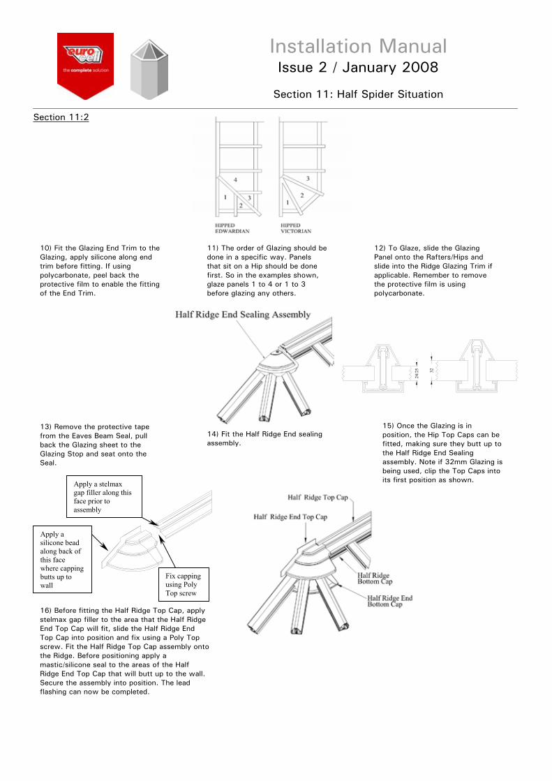
10) Fit the Glazing End Trim to theGlazing, apply silicone along end trim before fitting. If using polycarbonate, peel back the protective film to enable the fittingof the End Trim.
11) The order of Glazing should bedone in a specific way. Panels that sit on a Hip should be done first. So in the examples shown, glaze panels 1 to 4 or 1 to 3 before glazing any others.
12) To Glaze, slide the Glazing Panel onto the Rafters/Hips and slide into the Ridge Glazing Trim if applicable. Remember to remove the protective film is using polycarbonate.
13) Remove the protective tape from the Eaves Beam Seal, pull back the Glazing sheet to the Glazing Stop and seat onto the Seal.
14) Fit the Half Ridge End sealing assembly.
15) Once the Glazing is in position, the Hip Top Caps can be fitted, making sure they butt up tothe Half Ridge End Sealing assembly. Note if 32mm Glazing isbeing used, clip the Top Caps into its first position as shown.
16) Before fitting the Half Ridge Top Cap, apply stelmax gap filler to the area that the Half Ridge End Top Cap will fit, slide the Half Ridge End Top Cap into position and fix using a Poly Top screw. Fit the Half Ridge Top Cap assembly ontothe Ridge. Before positioning apply a mastic/silicone seal to the areas of the Half Ridge End Top Cap that will butt up to the wall. Secure the assembly into position. The lead flashing can now be completed.
Apply a stelmax gap filler along this face prior to assembly
Apply a silicone bead along back of this face where capping butts up to wall
Fix capping using Poly Top screw
32
24/2
5

Installation ManualIssue 2 / January 2008
Section 12: Tie Bar Installation
Section 12:1
NOTE: The Tie Bars are fitted BEFORE glazing of the roof commences
General Assembly of Tie Bars
1) Fit the Tie Bar Bracket on the specified Rafter in the position shown. Using the Bracket as a guide, mark through the hole centresand drill through the Rafter and Bottom Cap with a 6.5mm diameter drill.
2) Fix the Tie Bar Bracket to the Rafter using the screws and nuts provided. Once tightened, apply a silicone around the nut and bolt assembly.
3) Fix the Ridge Tie Bar Bracket to the underside of the Ridge using self-tapping countersunk screws.
Use Tie Bar Bracket as a guide for drilling hole centres.
Silicone aroundNut and Bolt assembly.
DECORATIVE COVER

Installation ManualIssue 2 / January 2008
Section 12: Tie Bar Installation
Section 12:2
4) Cut the vertical Tie Bar Rod so that the Centre Boss will align with the Rafter Tie Bar Brackets. Screw the vertical Tie Bar Rod into the Clevis Bracket and connect to the Ridge Tie Bar Bracket using the M10 x 30 nut and bolt. Push fit the PVC nut and bolt covers. Slide onto the Rod sufficient PVC Rod cover. Position the Centre Boss at the correct height by inserting the Vertical Tie Bar through the top junction and securing with an M10 bolt.
5) Cut a length of Tie Bar Rod to produce the horizontal Tie Bar. Screw one end into a Clevis Bracket.Connect the Clevis Bracket to the Rafter Tie Bar Bracket using the M10x 30 nut and bolt. Fit the PVC nut and bolt covers. Slide onto the Rod sufficient PVC rod cover. Connect the rod to the centre boss through the side junction and secure with an M10 bolt. Repeat this process for the other side.
6) Once satisfied that all Tie Rods are correctly positioned, fully tighten all fixings within the central boss.
7) Fit centre boss decorative plates by screwing together.

Installation ManualIssue 2 / January 2008
Section 12: Tie Bar Installation
Section 12:3
GENERAL ASSEMBLY OF TIE BARS TO INCORPORATE A FAN
The fitting of Tie Bars to incorporate a Fan is similar to a 3 Way Tie Bar
Except that two additional Rafter Tie Bar Brackets replace the Central Ridge
Tie Bar Bracket. The two additional Ties Bar Brackets must be positioned sufficiently
wide enough apart to allow for the fan blades.
Installation ManualIssue 2 / January 2008
Section 13: Bolster Bar Installation
Section 13:1
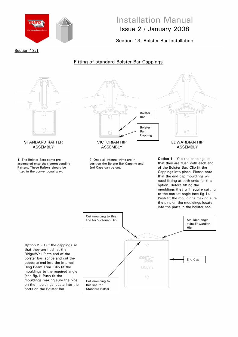
Fitting of standard Bolster Bar Cappings
1) The Bolster Bars come pre-assembled onto their corresponding Rafters. These Rafters should be fitted in the conventional way.
2) Once all internal trims are in position the Bolster Bar Capping and End Caps can be cut.
Option 1 – Cut the cappings so that they are flush with each end of the Bolster Bar. Clip fit the Cappings into place. Please note that the end cap mouldings will need fitting at both ends for this option. Before fitting the mouldings they will require cutting to the correct angle (see fig.1). Push fit the mouldings making surethe pins on the mouldings locate into the ports in the bolster bar.
Option 2 – Cut the cappings so that they are flush at the Ridge/Wall Plate end of the bolster bar, scribe and cut the opposite end into the Internal Ring Beam Trim. Clip fit the mouldings to the required angle (see fig.1) Push fit the mouldings making sure the pins on the mouldings locate into the ports on the Bolster Bar.
Bolster Bar
Bolster Bar Capping
Cut moulding to this line for Victorian Hip Moulded angle
suits Edwardian Hip
End Cap
Cut moulding to this line for Standard Rafter
STANDARD RAFTER ASSEMBLY
VICTORIAN HIP ASSEMBLY
EDWARDIAN HIP ASSEMBLY

Installation ManualIssue 2 / January 2008
Section 13: Bolster Bar Installation
Section 13:2
Fitting of Heavy Duty Bolster Bar Cappings
STANDARD RAFTER ASSEMBLY
VICTORIAN HIP ASSEMBLY
EDWARDIAN HIP ASSEMBLY
1) The Heavy Duty Bolster Bars come pre-assembled onto their corresponding rafters. These rafters should be fitted in the conventional way.
2) Once all internal trims are in position the Heavy Duty Bolster Bar Cappings and End Caps can be cut and fitted. There are two options available for the fitting of the cappings.
Option 1 – Cut the Cappings so that they are flush with each end of the Bolster Bar. Apply a continuous bead of silicone to inside bottom face of the cappings and push into position. Please note that the End Cap Mouldings will need fitting at both ends for this option. Before fitting the moulding correct angle. (see fig.1) Push fit the mouldings making sure that the pins on the mouldings locate intothe ports in the Bolster Bar.
Option 2 – Cut the Cappings so that they are flush at the Ridge/Wall Plate end of the Bolster Bar, scribe and cut the opposite end into the Internal Ring Beam Trim. Apply a continuous bead of silicone to the inside bottom face of the Cappings and push into position cut the moulding to the required angle (see fig.1). Push fit the moulding making sure the pins on the mouldings locate into the ports on the Bolster Bar.
Bolster Bar Capping
Heavy Duty Bolster Assembly
Moulded angle suitsEdwardian Hip
End Cap
Cut moulding to this line for Standard Rafter
Cut moulding to this line for Victorian Hip

Installation ManualIssue 2 / January 2008
Section 14: Updates
Section 14.1
Updates

Installation ManualIssue 2 / January 2008
Section 14: Updates
Section 14.1
Updates

www.eurocell.co.ukEurocell Profiles Ltd, Fairbrook House, Clover Nook Road, Alfreton, Derbyshire DE55 4RF
Tel: 01773 842100 Fax: 01773 838633 [email protected]