eurocell manual reve - gamry instruments
TRANSCRIPT

EuroCell™
Operator’s Manual

Limited Warranty
Gamry Instruments, Inc. warrants to the original user of this product that it shall be free of defects resulting
from faulty manufacture of the product or its components for a period of one year from the original
shipment date of your purchase.
Gamry Instruments, Inc. makes no warranties regarding either the satisfactory performance of this Cell Kit
or the fitness of the product for any particular purpose. The remedy for breach of this Limited Warranty
shall be limited solely to repair or by replacement, as determined by Gamry Instruments, Inc., and shall not
include other damages.
Gamry Instruments, Inc. reserves the right to make revisions to the product at any time without incurring
any obligation to install same on systems previously purchased. All product specifications are subject to
change without notice.
There are no warranties which extend beyond the description herein. This warranty is in lieu of, and
excludes any and all other warranties or representations, expressed, implied or statutory, including
merchantability and fitness, as well as any and all other obligations or liabilities of Gamry
Instruments, Inc.; including but not limited to, special or consequential damages.
This Limited Warranty gives you specific legal rights and you may have others which vary from state to
state. Some states do not allow for the exclusion of incidental or consequential damages.
No person, firm or corporation is authorized to assume for Gamry Instruments, Inc., any additional
obligation or liability not expressly provided herein except in writing duly executed by an officer of Gamry
Instruments, Inc.

EuroCell™
Operator’s Manual
Part number 988-0002
Copyright 2014−2017 Gamry Instruments, Inc.
Revision 1.31
November 28, 2017
If You Have Problems
Please visit our service and support page at www.gamry.com/service-support/.
This page contains information on installation, software updates, and training. It also contains links to the
latest available documentation. If you are unable to locate the information you need from our website, you
can contact us via email using the link provided on our website. Alternatively, you can contact us one of
the following ways:
Internet www.gamry.com/service-support/
Telephone (215) 682-9330 9:00 AM - 5:00 PM US Eastern Standard Time
(877) 367-4267 Toll-free US & Canada Only
Replacement parts for this kit are available from Gamry Instruments, Inc. Optional parts may be available
from Gamry Instruments, or from third-party vendors. Contact your local Gamry sales representative to
discuss any special requirements or accessories that you need.
Disclaimer
The information in this manual has been carefully checked and is believed to be accurate as of the time of
printing. However, Gamry Instruments, Inc. assumes no responsibility for errors that might appear.
Copyrights and Trademarks
EuroCell™ Manual copyright 2014−2017 Gamry Instruments, Inc.
VistaShield™ copyright 2017 Gamry Instruments, Inc.
Viton® is a registered trademark of The Chemours Company.
Kalrez® is a registered trademark of DuPont Performance Elastomers.
ACE-Thred™ is a trademark of Ace Glass, Inc.
Pyrex® is a registered trademark of Corning Incorporated.
No part of this document may be copied or reproduced in any form without the prior written consent of
Gamry Instruments, Inc.

Table of Contents
Limited Warranty ........................................................................................................................... ii Introduction ................................................................................................................................... 1 Chemical Compatibility of the EuroCell .......................................................................................... 2 Unpacking and Checking a Cell Kit ................................................................................................. 3
Checking for Shipping Damage ......................................................................................... 3 Parts List ........................................................................................................................... 4
Assembly of and Use of Your Cell Kit .............................................................................................. 5 Cell Assembly: General Information................................................................................... 5
Gas-flow Overview and Terminology .................................................................... 7 Pre-saturation of the Purge Gas ............................................................................ 8 EuroCell Gas Bubbler Assembly ............................................................................ 8
Attaching Gas Tubing to the Cell ....................................................................................... 9 Counter Electrode Assembly .............................................................................................. 10
Counter Electrode Overview and Terminology ...................................................... 10 High-Density Graphite Counter Electrodes ........................................................... 10 EuroCell Counter Electrode: Optional Isolated Assembly ....................................... 11
Reference Electrode and Bridge Tube ............................................................................... 11 Overview and Terminology .................................................................................. 11 Bridge Tube and Reference Electrode Assembly .................................................... 12 Bridge Tube and Reference Electrode: Maintenance and Care .............................. 13
Sample Holder Assembly .................................................................................................. 15 Spare Port ............................................................................................................ 17 Addition of Corrosive Agents ................................................................................ 17 Temperature Sensing, and Control ....................................................................... 17 Addition of a pH Electrode ................................................................................... 17 Getting a Stir Bar into the Cell .............................................................................. 17 Moving the Pieces About ..................................................................................... 17
Electrode Connections ................................................................................................................... 18 Troubleshooting ............................................................................................................................. 19 Specifications ................................................................................................................................. 21 Index ............................................................................................................................................. 22

Introduction--Checking for Shipping Damage
1
Introduction
Gamry Instruments designed the EuroCell™ kit for electrochemical corrosion testing. Like Gamry’s Multiport, it
is used with cylindrical metal specimens. The EuroCell is more versatile and less expensive than the Multiport,
and is an alternative to the Multiport.
A commercial source of suitable cylindrical specimens is the P/N 410 series from Alabama Specialty Products.
They have cylindrical samples available in several hundred different metals. They can be contacted at:
Metal Samples Co., Inc.
152 Metal Samples Road
P.O. Box 8
Munford, AL 36268 USA
Telephone: (256) 358-4202
Fax: (256) 358-4515
Email: [email protected]
Your Euro Corrosion Cell kit was shipped with one Alabama Specialty Products P/N 410 Series sample. The
sample material is C1018 mild steel. Most of the pieces required to run routine experiments are included in
EuroCell kit.
The EuroCell uses five standard ports to implement its required functions. You can customize the cell by
rearranging some of Gamry’s standard fittings or making or buying additional fittings, electrodes, sensors or
adapters.
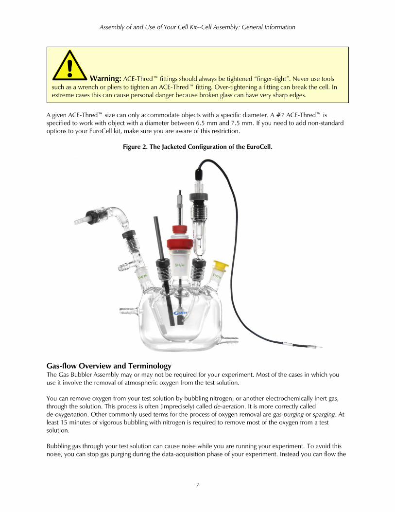
Too often, temperature control is neglected in designing electrochemical experiments. Temperature is an
important variable in the rate of both heterogeneous and homogeneous chemical reactions. Comparing test
results recorded at different temperatures can be vital in gaining a full understanding of a chemical system. For
these reasons, Gamry sells a special jacketed version of the EuroCell cell body. When this cell is connected to a
circulating water bath, accurate temperature control of your experiments becomes possible.
A reference electrode is not included in the cell kit. Requirements for this electrode vary too
much from user to user to make its inclusion in the standard kit practical. Gamry Instruments sells three
types of reference electrodes (SCE, Ag|AgCl, and Hg|Hg2SO4) that are suitable for use with your EuroCell
kit. Order your reference electrode separately.
Chemical Compatibility of the EuroCell--Checking for Shipping Damage
2
Chemical Compatibility of the EuroCell
The components in the EuroCell were selected to be as chemically inert as possible. In normal use, the only
materials in contact with the test solution are:
• The corrosion sample
• Borosilicate glass (Pyrex® or equivalent)
• unfired glass frit
• PTFE
• polyethylene
• Ace Glass’s FETFE O-ring material
Chemical resistance tables for most of these materials are available (try searching the Internet). One exception is
FETFE, which is a elastomer proprietary to Ace Glass, which consists of PTFE particles in a fluorinated rubber
base similar to Viton®. According to Ace Glass, it offers slightly better chemical resistance than Viton
®.
The black ACE-Thred™ fittings supplied with the cell do not normally come in contact with the cell electrolyte.
These are nylon fittings, so you can use nylon’s properties (which are generally available) as an indication of
these fitting’s suitability for use in any specific chemical environment.
Gamry’s EuroCell was not designed for use in electrolytes that dissolve glass (extremely basic solutions or HF-
containing solutions).
The simple construction of the polyethylene stoppers used to seal the unused port makes them easily adaptable
as a vent for purge gas: you simply poke a hole in the flat surface of the stopper. While they provide chemical
resistance to most aqueous electrolytes, they may not be a good choice for use with some aggressive solvents. If
polyethylene is not suitable for your application, glass and PTFE stoppers are available from most laboratory
supply houses. If you use these “more solid” stoppers, do not forget the need to vent purge gas from the cell.
Caution: The glass components in the cell and the glass frits used in the reference bridge
tube are not suitable for use with extremely basic solutions or solutions containing hydrofluoric acid. We do
not know of any substitute cell components that will completely overcome this limitation. If you need to
work with solutions that will damage the EuroCell cell, we recommend that you design and build an all-
plastic cell.
Caution: The nylon bushings in the ACE-Thred fittings and the FETFE O-rings may not be
suitable for use in some electrolytes (particularly non-aqueous media). If you need better chemical
resistance than that offered using the standard ACE-Thred components, ACE Glass (www.aceglass.com) can
provide replacement fittings made from PTFE and Kalrez®, which are extremely resistant to chemical attack.
Contact Gamry Instruments, if you need help selecting the proper replacement fittings.
Unpacking and Checking a Cell Kit--Checking for Shipping Damage
3
Unpacking and Checking a Cell Kit
This section is primarily intended for the user who has just received a new EuroCell Kit.
Checking for Shipping Damage
Your new EuroCell kit was shipped disassembled to minimize shipping damage. All of the pieces have been
carefully packaged in anticipation of rough handling in shipment. Unfortunately, no matter how carefully glass
pieces are packaged, damage will sometimes occur.
When you first receive your EuroCell kit, please check it for any signs of shipping damage. Be especially careful
if the shipping container shows signs of rough handling.
Obviously, the glass pieces are the most susceptible to damage. Check the glass pieces for chipping and small
cracks as well as for major damage.
If any parts were broken in shipment, please contact our US facility or your local Gamry representative as soon
as possible. In most cases, Gamry should have replacement parts in stock. Please retain the shipment’s
packaging material for a possible claim against the shipping company.
If any parts have been broken in shipment, please contact our US facility or your local Gamry representative as
soon as possible. In most cases, Gamry should have replacement parts in stock. Please retain the shipment’s
packaging material for a possible claim against the shipping company.
Warning: Do not use any glass parts that are chipped or cracked. Any damage to glass
increases the probability of additional damage. Broken glass can have extremely sharp edges that represent
a significant safety hazard. Injuries from broken glass can be quite severe.

Unpacking and Checking a Cell Kit--Parts List
4
Parts List
Please check the contents of your kit versus the EuroCell kit packing list in Table 1. When shipped, all of the
EuroCell kit components should be labeled with their Gamry Instruments, Inc. part number.
If you are checking the completeness of an older kit, you can identify the components by name using the
illustrations in Figure 1 later in this manual.
Table 1
EuroCell Kit Packing List
Quantity P/N Description
2 820-00001 PTFE Compression Gasket
2 820-00004 Sample Rod Centering Washer
1 820-00005 C1018 Sample, Cylinder
1 820-00036 Sample Rod, Threaded
1 850-00005 Standoff, Hex 8-32 Threaded
1 930-00030* EuroCell Cell Body (incl. 2 #7 bushing with O-ring)
1 930-00041** EuroCell Cell Body, jacketed (incl. 2 #7 bushing with O-ring)
1 930-00033 Gas Flow Adapter
1 930-00039 Tube, Glass, Elect Holder, EuroCell
1 930-00040 Bubbler, Ace to Frit
3 930-00042 Glass Frit with PTFE Heat-shrink Tubing
1 930-00045 Reference Electrode Bridge Tube, EuroCell with glass frit
1 935-00005 Adapter, 24/40 to 8 mm Tube
1 935-00014 Graphite counter electrode
1 935-00053 #11 ACE-Thred™ Bushing, Nylon with 2 O-rings
1 935-00054 Adapter, #7 ACE-Thred™ to ¼” hose
5 935-00059 Polyethylene Stoppers for 14/20 Joint
1 988-00002 Manual, EuroCell
*Only included in the Standard EuroCell configuration, 990-00196 (no stand).
**Only included in the Jacketed EuroCell configuration, 990-00203.
Contact us as soon as possible if any of the parts are missing. The contact information for our US facility is on
the first pages of this manual. If you are outside the US, you may want to contact your local Gamry
representative.

Assembly of and Use of Your Cell Kit--Cell Assembly: General Information
5
Assembly of and Use of Your Cell Kit
This section of the manual tells you how to assemble and use a EuroCell kit in its standard configuration.
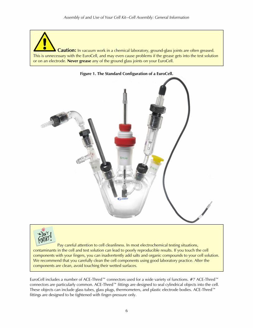
This “standard” cell configuration has:
• A standard cell body for use at room temperature
• A corrosion sample in the central 24/40 standard-taper port
• A three-way gas purge/blanket/vent adapter in one 14/20 standard-taper port
• A graphite-rod counter electrode in one #7 ACE-Thred™ port
• A reference electrode and bridge tube in one #7 ACE-Thred™ port
• One unused 14/20 standard taper port (may be closed with a stopper)
This is one of many possible cell configurations. Feel free to customize your EuroCell. You are only limited by
your imagination and the number and size of the ports available on the top of the cell.
Cell Assembly: General Information
A picture of an assembled cell is shown in Figure 1.
Your kit was shipped to you with a C1018 mild steel metal sample. Please use this sample to try out the
assembly of your cell as you read this section of the manual.
If you are assembling your EuroCell kit for the first time, you may want to assemble the entire cell dry first. After
you are comfortable with the cell’s assembly, you can fill the cell with a test solution and run real tests.
We recommend that you start the assembly of your cell by clamping the cell body in a three-fingered clamp
attached to a ring stand. Gamry sells a ring-stand kit which can be purchased using part number 990-00202.
Alternatively, these can be purchased from any supplier of laboratory equipment. The cell body is not stable
when laid on a flat surface such as a lab bench and can easily roll off a bench onto the floor with cell-shattering
results. Gamry Instruments can always use additional sales, but we hate to have them come in the form of
replacement cell bodies!
Three of the ports on EuroCell are standard-taper ground-glass joints. Never grease these joints.
Caution: Always assume that the cell body will roll a substantial distance if laid down on a
flat surface. Guard against it rolling off your test bench. Gamry’s optional Cell Stand Kit (part # 990-00202)
for the EuroCell can be very useful in preventing this type of accident.
Assembly of and Use of Your Cell Kit--Cell Assembly: General Information
6
Figure 1. The Standard Configuration of a EuroCell.
EuroCell includes a number of ACE-Thred™ connectors used for a wide variety of functions. #7 ACE-Thred™
connectors are particularly common. ACE-Thred™ fittings are designed to seal cylindrical objects into the cell.
These objects can include glass tubes, glass plugs, thermometers, and plastic electrode bodies. ACE-Thred™
fittings are designed to be tightened with finger-pressure only.
Pay careful attention to cell cleanliness. In most electrochemical testing situations,
contaminants in the cell and test solution can lead to poorly reproducible results. If you touch the cell
components with your fingers, you can inadvertently add salts and organic compounds to your cell solution.
We recommend that you carefully clean the cell components using good laboratory practice. After the
components are clean, avoid touching their wetted surfaces.
Caution: In vacuum work in a chemical laboratory, ground-glass joints are often greased.
This is unnecessary with the EuroCell, and may even cause problems if the grease gets into the test solution
or on an electrode. Never grease any of the ground glass joints on your EuroCell.
Assembly of and Use of Your Cell Kit--Cell Assembly: General Information
7
A given ACE-Thred™ size can only accommodate objects with a specific diameter. A #7 ACE-Thred™ is
specified to work with object with a diameter between 6.5 mm and 7.5 mm. If you need to add non-standard
options to your EuroCell kit, make sure you are aware of this restriction.
Figure 2. The Jacketed Configuration of the EuroCell.
Gas-flow Overview and Terminology
The Gas Bubbler Assembly may or may not be required for your experiment. Most of the cases in which you
use it involve the removal of atmospheric oxygen from the test solution.
You can remove oxygen from your test solution by bubbling nitrogen, or another electrochemically inert gas,
through the solution. This process is often (imprecisely) called de-aeration. It is more correctly called
de-oxygenation. Other commonly used terms for the process of oxygen removal are gas-purging or sparging. At
least 15 minutes of vigorous bubbling with nitrogen is required to remove most of the oxygen from a test
solution.
Bubbling gas through your test solution can cause noise while you are running your experiment. To avoid this
noise, you can stop gas purging during the data-acquisition phase of your experiment. Instead you can flow the
Warning: ACE-Thred™ fittings should always be tightened “finger-tight”. Never use tools
such as a wrench or pliers to tighten an ACE-Thred™ fitting. Over-tightening a fitting can break the cell. In
extreme cases this can cause personal danger because broken glass can have very sharp edges.
Assembly of and Use of Your Cell Kit--Cell Assembly: General Information
8
inert gas over the top of the test solution, often referred to as “blanketing” the cell. In general, blanketing is used
after solution purging, where blanketing prevents acquiring new oxygen from the gas above the solution.
Many modern electrochemical test systems include automatic control of gas flow in their experimental
sequencing. This is true of Gamry Instruments’ Pulse Voltammetry and Physical Electrochemistry systems. These
systems generate a digital signal that is intended to control a solenoid valve, which in turn routes gas flow to the
cell. Gamry’s VistaShield™ Faraday cage, when equipped with its Purge and Stir option, provides a complete
solution for purge-gas control.
Pre-saturation of the Purge Gas
Bubbling dry purge gas through your cell electrolyte can cause significant evaporation of the electrolyte’s solvent
during the purge process. This can be a significant source of error in some experiments. This problem can often
be avoided by pre-saturation of the purge gas with the electrolyte prior to it entering the cell. This is commonly
done using a “gas washing bottle,” which can be obtained at most laboratory supply companies.
The EuroCell kit does not include a gas washing bottle, for they are already available in many laboratories.
EuroCell Gas Bubbler Assembly
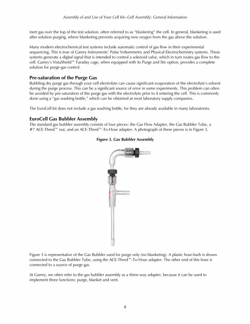
The standard gas bubbler assembly consists of four pieces: the Gas Flow Adapter, the Gas Bubbler Tube, a
#7 ACE-Thred™ nut, and an ACE-Thred™-To-Hose adapter. A photograph of these pieces is in Figure 3.
Figure 3. Gas Bubbler Assembly
Figure 3 is representative of the Gas Bubbler used for purge only (no blanketing). A plastic hose-barb is shown
connected to the Gas Bubbler Tube, using the ACE-Thred™-To-Hose adapter. The other end of this hose is
connected to a source of purge gas.
At Gamry, we often refer to the gas bubbler assembly as a three-way adapter, because it can be used to
implement three functions: purge, blanket and vent.
Assembly of and Use of Your Cell Kit--Attaching Gas Tubing to the Cell
9
The vent function is critical. Regardless of whether gas is flowing through or over the test solution, you must
provide a way for it leave the cell. If you, do not, the gas may not flow, or worse, the cell may burst apart
unexpectedly. Not providing a vent for the escape of purge gas is a very common and often dangerous
“mistake” made when setting up an electrochemical cell.
In normal use, the Gas Flow Adapter is installed in one of the 14/20 ground-glass ports on your EuroCell. The
Gas Bubbler Tube, with an O-ring installed as shown in Figure 3, is slid into a #7 ACE-Thred™ port on top of
the Gas Flow Adapter. When you are satisfied with position of the Gas Bubbler Tube, tighten the ACE-Thred™
nut.
Attaching Gas Tubing to the Cell
The position of the Gas Bubbler Tube is normally adjusted so its orifice end sits in the cell’s electrolyte. The
hose barb on the side of the Gas Flow Adapter can be used as a vent or as an inlet for blanket gas.
Connect the gas-flow system and add the cell electrolyte before the needle valve is turned on. Open the valve
slowly, while you watch the bubbles in the cell. Bubbling should not be vigorous enough to splash large
quantities of electrolyte on the cell walls.
In addition to the needle valve, a three-way valve is very useful in purge and blanket gas control. Three-way
valves are available in both electrically switched and manual versions. A three-way valve switches one gas
stream so it flows from a single inlet to one of two outlets.
If your system includes a three-way valve for switched purge and blanket gas control, we recommend that you:
• Connect the purge gas to the ACE-Thred™-To-Hose adapter on top of the Gas Bubbler Tube
• Connect the blanket gas to the hose barb on the side of the Gas Flow Adapter
• Use the spare port to provide a vent. A small hole poked into one of the polyethylene stoppers in the
cell kit is generally a sufficient vent.
If you do not have a three-way gas-control valve, you can switch from purge mode to blanket mode manually.
Connect the gas flow to the ACE-Thred™-To-Hose adapter. When you want to purge, loosen the ACE-Thred™
Warning: Your gas flow system should include a needle valve to control the gas flow rate.
Make all gas tubing connections to the cell with this valve turned all the way off. Making connection with a
cell filled with electrolyte or adding electrolyte to a system when the gas flow is on can lead to severe
accidents. Excessive gas flow can damage the cell and result in a loss of electrolyte. In extreme cases, this
can represent a significant safety hazard.
Warning: If you use purge of blanket gas, you must provide a vent for the gas to escape the
cell. EuroCell was not designed to withstand gas pressure! Failure to vent the cell can cause damage to the
cell, uncontrolled loss of electrolyte from the cell, and risk of personal injury to the cell’s operator.

Assembly of and Use of Your Cell Kit--Counter Electrode Assembly
10
nut holding the Gas Bubbler tube in place, slide the Gas Bubbler Tube deeply into the cell so its orifice is in the
cell solution, then retighten the ACE-Thred™ fitting. When you want to blanket, slide the Gas Bubbler Tube far
out of the cell, so its orifice is above the solution. When you use the cell in this way, the hose barb port on the
Gas Flow Adapter provides a convenient vent.
Counter Electrode Assembly
Counter Electrode Overview and Terminology
The counter electrode in a three-electrode electrochemical experiment is generally an inert metal or carbon
electrode that provides a source or sink of electrons to the cell. Another term used for this electrode in the
auxiliary electrode.
The electrochemist is generally not interested in the reactions that occur at the counter electrode. One
exception is when the reactions at the counter electrode produce a soluble product that can diffuse to the
working electrode and interfere with its operation. In this case, the electrochemist may want a diffusion barrier
to isolate the counter electrode compartment from the rest of the cell. A glass frit is commonly used as an
isolation barrier.
High-Density Graphite Counter Electrodes
Your EuroCell kit comes with a high-density graphite rod counter electrode (150 mm long × approx. 6.3 mm
dia.). It fits nicely in a #7 ACE-Thred™ port. The Gamry Instruments part number for replacement graphite rods
is 935-00014.
To use this graphite rod as the counter electrode in the EuroCell, slide the O-ring from the ACE-Thred port
directly onto the graphite rod and place the rod into the port, until the desired length of the rod is immersed in
the electrolyte.
The graphite rod that is shipped with your EuroCell is spectroscopic grade. It is very pure and therefore is
unlikely to be a significant source of contamination in your initial experiment. However, the rod is somewhat
porous and can adsorb substances present in your test solution. If you reuse a graphite rod, it can contaminate
your test solution. The effect is small, and you are unlikely to see it unless the test solution changes drastically
between tests.
Assembly of and Use of Your Cell Kit--Reference Electrode and Bridge Tube
11
EuroCell Counter Electrode: Optional Isolated Assembly
In the standard configuration of the EuroCell, the counter electrode is a graphite rod, which is immersed
directly in the test solution.
In some cases, you may want your counter electrode isolated from the bulk solution by a glass frit. Gamry
Instruments sells an Isolated Counter Electrode kit (Part Number 990-00194) that works with both the EuroCell
and the PTC1 Paint Test Cell kit.
There are two pieces in this isolated counter electrode kit:
• A fritted isolation tube
• 150 mm of platinum wire.
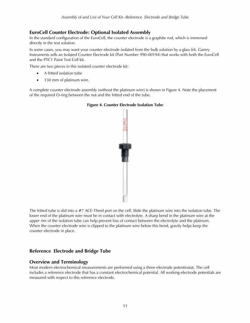
A complete counter electrode assembly (without the platinum wire) is shown in Figure 4. Note the placement
of the required O-ring between the nut and the fritted end of the tube.
Figure 4. Counter Electrode Isolation Tube
The fritted tube is slid into a #7 ACE-Thred port on the cell. Slide the platinum wire into the isolation tube. The
lower end of the platinum wire must be in contact with electrolyte. A sharp bend in the platinum wire at the
upper rim of the isolation tube can help prevent loss of contact between the electrolyte and the platinum.
When the counter electrode wire is clipped to the platinum wire below this bend, gravity helps keep the
counter electrode in place.
Reference Electrode and Bridge Tube
Overview and Terminology
Most modern electrochemical measurements are performed using a three-electrode potentiostat. The cell
includes a reference electrode that has a constant electrochemical potential. All working-electrode potentials are
measured with respect to this reference electrode.
Assembly of and Use of Your Cell Kit--Reference Electrode and Bridge Tube
12
In many cases, placing the reference electrode directly in the test electrolyte can be a problem. Examples
include:
• When the reference electrode is large, making it inconvenient to use in a small volume
• When the reference electrode’s filling solution will contaminate the electrolyte
• When the cell is heated and you do not want the reference potential to change with cell temperature
To avoid these problems, EuroCell always uses a bridge tube to locate the reference electrode above the cell.
The bridge tube is a glass tube filled with electrolyte that provides a conductive path from the cell electrolyte to
the tip of the reference electrode. The electrolyte in the bridge tube is usually identical to the cell electrolyte,
but in some cases a different electrolyte may be necessary.
A bridge tube is similar, but not identical, to a Luggin capillary. A Luggin capillary attempts to move the “sensing
point” of the reference electrode close to the working electrode’s surface. The bridge tube in EuroCell has too
large a tip for it to qualify as a true Luggin capillary.
The bridge tube in EuroCell is particularly convenient, because it terminates in an unfired glass frit, which
makes filling the bridge tube easy yet doesn’t add a lot of resistance to the reference electrode circuit. Most
other bridge tube or Luggin capillary designs either have excessive resistance causing noisy data, potentiostat
oscillation, or are difficult to fill with electrolyte.
Bridge Tube and Reference Electrode Assembly
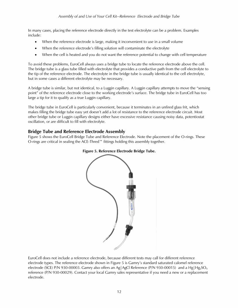
Figure 5 shows the EuroCell Bridge Tube and Reference Electrode. Note the placement of the O-rings. These
O-rings are critical in sealing the ACE-Thred™ fittings holding this assembly together.
Figure 5. Reference Electrode Bridge Tube.
EuroCell does not include a reference electrode, because different tests may call for different reference
electrode types. The reference electrode shown in Figure 5 is Gamry’s standard saturated calomel reference
electrode (SCE) P/N 930-00003. Gamry also offers an Ag|AgCl Reference (P/N 930-00015) and a Hg|Hg2SO4
reference (P/N 930-00029). Contact your local Gamry sales representative if you need a new or a replacement
electrode.
Assembly of and Use of Your Cell Kit--Reference Electrode and Bridge Tube
13
EuroCell can be used with third-party reference electrodes, if the reference electrode diameter is between 9
and 10.5 mm.
To fill, assemble, and install the bridge tube and reference electrode:
1) Place an O-ring and #7 ACE-Thred™ fitting on the middle section of the bridge tube (see Figure 5).
2) Place an O-ring and #11 ACE-Thred™ fitting on the reference electrode (see Figure 5).
3) Pour electrolyte into the larger-diameter end of the bridge tube, leaving about 2.5 cm between the
bottom of the ACE-Thred™ and the top of the electrolyte.
4) Place the reference electrode, tip first, into the larger end of the bridge tube and tighten the #11 ACE-
Thred™ fitting until it is finger-tight, so that the reference electrode is fixed in place.
5) Place the smaller end of the bridge tube into one of ACE-Thred™ ports on your EuroCell.
6) Adjust the height of the bridge tube so that its tip will be in the electrolyte and close to the working
electrode.
7) Tighten the bridge tube’s #7 ACE-Thred™ fitting until it is finger-tight and the bridge tube is held firmly
in place.
Bridge Tube and Reference Electrode: Maintenance and Care
The unfired glass-frit tips used on both the reference electrode and the bridge tube are subject to cracking when
allowed to go from a wetted to a dry state.
Your EuroCell kit contains three replacement frits with heat-shrinkable PTFE sleeves. Use one of these
whenever you need to replace a damaged frit.
Whenever possible store the bridge tube tip in the electrolyte used in your system. Place the bridge tube tip
down, in a flask containing the electrolyte you use in your tests.
If you cannot keep the frit wetted with electrolyte, you can store the bridge tube tip in the solvent that it will be
exposed to during testing. In aqueous testing, always use high quality de-ionized or distilled water. The glass
frits have a very large surface area which absorbs contaminants from impure solvents.
Periodically, it may be necessary to replace the glass frits on the reference electrode and bridge tube. EuroCell
comes with three spare glass frits with heat-shrinkable PTFE tubing.
To replace the frit of the bridge tube:
1. Make sure the bridge tube is clean and dry.
2. Cut the old frit off with a sharp blade, taking care not to cut yourself.
Caution: Do not allow the glass frits on the reference electrode or the bridge tube to dry
out. They are likely to crack, greatly increasing the flow of bridge-tube or reference filling solution into your
cell. If the frit does dry out, we recommend that you replace it.
Assembly of and Use of Your Cell Kit--Reference Electrode and Bridge Tube
14
3. Turn the tube upside down and place the PTFE sleeve over the end of the tube.
4. Insert the piece of glass frit in the sleeve and then heat the sleeve with a heat gun to shrink the PTFE
sleeve around the glass frit.
5. Trim the sleeve to be flush with the exposed end of the glass frit.
A similar procedure can be accomplished with the reference electrode, however it may be difficult to empty.
Instead just turn it upside down and keep the solution away from the tip.
Caution: Take care when using a heat gun to avoid burning oneself.
The reference electrode is also supplied with a clear plastic sleeve covering a fill hole in its glass body. This fill
hole serves two purposes:
• It allows you to refill the electrode with saturated KCl if the liquid level in the electrode drops.
• It also provides a vent, so the filling solution flows slowly out of the electrode.
In normal use, we recommend that the fill hole be kept slightly open. When storing the electrode, the fill hole
should be closed.
Gamry’s Reference electrodes are shipped with a black plastic sleeve covering the electrode tip. This tip is
effective in keeping the reference electrode’s glass-frit tip wet. A plastic sleeve on one side of Bridge Tube’s
glass-frit tip will not keep the bridge tube tip wet, unless the tube is filled with solvent or electrolyte.
Caution: Do not use a plastic sleeve to cover the Bridge Tube’s glass-frit tip, unless the
other side of the tip is covered with solvent or electrolyte. If the tip dries out, it is likely to crack, causing
irreproducible results in your electrochemical tests.
If the electrode or the bridge tube has been stored in a pure, poorly conductive solvent, the
glass-frit tip must refill with ions prior to use. In the case of the reference electrode, half an hour with the
vent hole open should suffice. In the case of the Bridge Tube, half a hour with a vented reference electrode
in place should also be sufficient.
Warning: Be careful when cutting off the old fit, to prevent injury. Never cut
towards your body.
Assembly of and Use of Your Cell Kit--Sample Holder Assembly
15
Sample Holder Assembly
The Sample Holder is generally the last part inserted into the cell. If you are deoxygenating your test solution,
do so before placing the test sample into the solution.
Surface finish of the sample and other sample preparations are critical if you want to obtain reproducible
results. Consult the corrosion measurement literature for details about the handling of corrosion test specimens.
Many of the surface preparation techniques used for weight-loss coupons are also applicable to electrochemical
test specimens.
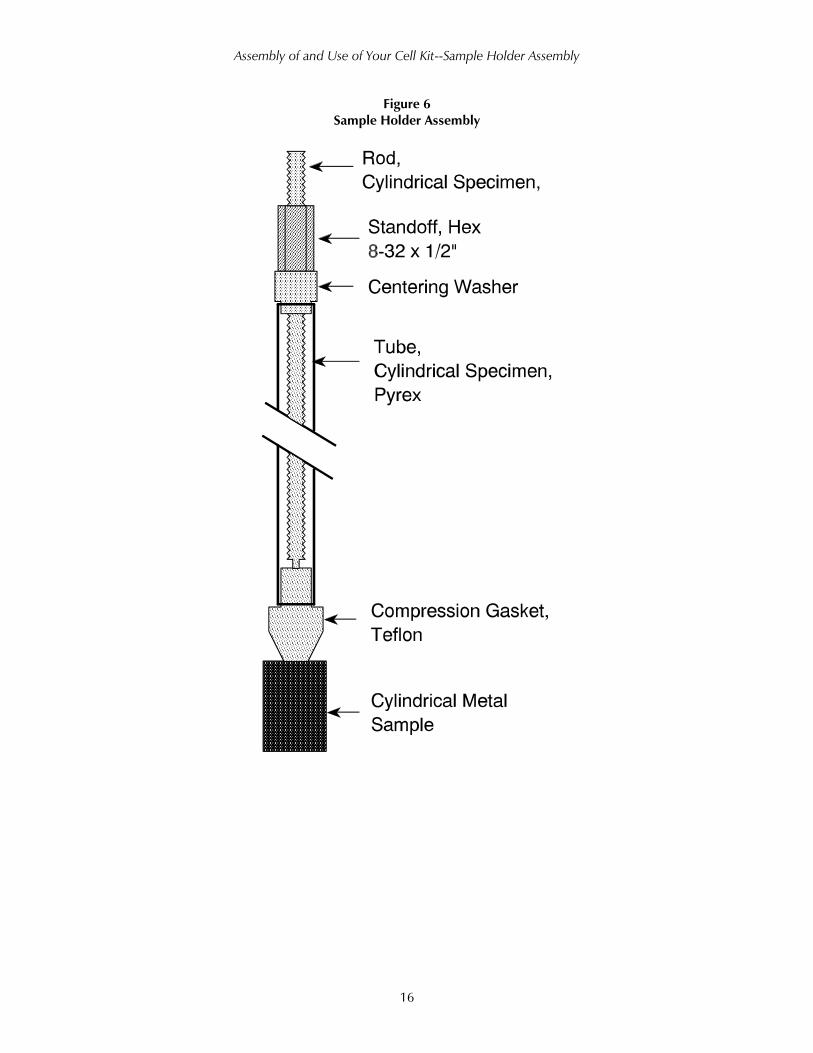
A diagram of an assembled Sample Holder is in Figure 6. A threaded rod is used to hold the assembly together
and to provide electrical contact with the metal sample. The PTFE Compression Gasket is used to prevent
leakage of solution into the interior of the glass rod. The sealing surfaces of this gasket must be smooth or a
good seal cannot be obtained.
Put together the assembly loosely before tightening the Hex Standoff. Consult the diagram in Figure 6 for the
position of the Sample Holder components. The centering washer has a small protrusion on one surface; the
other surface is flat. The side with the protrusion side faces into the glass tube.
The Hex Standoff at the top of the assembly is tightened while the metal sample is held on the other end. Only
tighten the assembly finger-tight.
A small amount of bending in the glass tube may occur when you tighten the assembly. This is normal and no
cause for concern.
Caution: Never use a wrench to tighten the Sample Holder Assembly. Doing so can
damage the PTFE Compression Gasket or even break the glass tube.
Take great care to insure that the surface of your test sample is not altered prior to the test.
Avoid contacting the sample with your fingers. You may want to degrease the metal sample mounted on
the Sample Holder just prior to starting your test.
Assembly of and Use of Your Cell Kit--Sample Holder Assembly
16
Figure 6
Sample Holder Assembly
Assembly of and Use of Your Cell Kit--Sample Holder Assembly
17
Spare Port
The normal EuroCell configuration includes a spare 14/20 port. If you really never use this port, you can cap it
with one of the 14/20 plastic stoppers included in your cell kit. Remember to poke a vent hole in this stopper if
you will have gas flowing into your cell and there is no other gas vent available.
You can also use this spare port for customizing your system. A few examples are listed below.
Addition of Corrosive Agents
In many experiments, you record a baseline curve before you add a vital reactant to the cell. You then add that
reactant, stir the cell, then record another curve. Many of Gamry’s analysis packages allow you to subtract the
baseline curve from the data curve. The resulting curve shows only electrochemistry related to this reactant.
Another common use for added reactant is current-versus-concentration studies.
To add reactant, remove the stopper, add the reactant, then replace the stopper.
Temperature Sensing, and Control
The rate of almost all chemical reactions is strongly temperature-dependent. For this reason, you may want to
either measure or control the temperature of your cell.
Ace Glass has thermometer adapters that are designed to mount a standard lab thermometer to a 14/20
ground-glass joint. One example is Ace part number 5028-26. This is an convenient way to add temperature
measurement to your system.
In many cases, temperature must be controlled, not measured. One way to do this is:
1. Purchase the jacketed option for the EuroCell. This is a special cell body (Gamry
part number 930-00041) that allows a flowing temperature-transfer fluid to encase the cell.
2. Plumb the jacket on the cell to a recirculating constant-temperature bath.
3. If the bath offers remote temperature sensing, place a sensor in the spare port of the cell. This may
require purchase of another option (for example an RTD-to-14/20-port adapter).
In some cases, Gamry’s software supports setting automatically the temperature. Add the controlled
temperature to the experiment’s Setup window, and the software controls the temperature bath via an RS-232
port. In other cases, a modified script is required.
Addition of a pH Electrode
Another possible use for the space port is addition of a pH electrode. Again, an adapter is required.
Getting a Stir Bar into the Cell
If you want to magnetically stir, and you forget to add a stir bar to your cell, you can add it using the spare port.
Moving the Pieces About
There are several circumstances in which the standard cell configuration may not work. One is a larger-than-
normal working or reference electrode.
There is no requirement that any electrode or adapter mount in any specific port. However, the main port
(24/40 joint) has the largest diameter of all the ports.
Electrode Connections--
18
Electrode Connections
If you are using your EuroCell with a Gamry Instruments potentiostat, make the following connections to the
electrodes.
The Reference Electrode lead plugs into the white pin jack on the cell cable.
The green and blue leads from the cell cable are attached to the Working Electrode. Cell currents in a EuroCell
experiment are often large enough that you should clip the blue and green leads separately to the working
electrode.
The red lead on the cell cable clips to the Counter Electrode.
Make sure that the long black lead on the cell cable cannot touch any other cell connection. You may find that
connection of this lead to a source of earth ground, such as a water pipe, will reduce noise in your experimental
results.
If you are measuring very small currents, you may find that a metal enclosure completely surrounding your cell
will further reduce noise. In this case, connect the shield, known as a Faraday cage, to an earth ground. Then
connect the black lead from the cell cable to the Faraday shield.
Gamry’s VistaShield is a versatile, easy-to-use Faraday cage that was designed to work well with the EuroCell
kit. When equipped with a Purge and Stir option, it provides a complete electrochemical corrosion test stand,
well integrated with Gamry’s cells, potentiostats, and software systems.
Always double-check your cell connections. Even an experienced experimentalist will
occasionally leave one of the cell cable leads lying on the desktop.
Some potentiostats may not include a blue clip lead. In this case, connect only the green lead
to the Working Electrode.
Troubleshooting--
19
Troubleshooting
By far, the most common source of problems is lack of a connection between a cell lead and the cell
electrolyte. The lack of connection can be between the potentiostat and the electrode, or between the
electrode and the electrolyte.
One very common and often embarrassing error is to forget to connect one of the cell leads! Always double-
check your cell connections.
A more subtle problem is a gas bubble blocking an electrode’s access to the electrolyte. Places where this can
happen include:
• Purge gas or gaseous reaction products collecting on the face of the working electrode.
• The counter electrode wire is not in the solution.
• If you have a counter isolation tube, it can fail to fill with electrolyte.
• The Reference Bridge tube contains a bubble between the reference electrode and the electrolyte.
• A bubble collects on the glass frit at the end of the reference electrode.
Another common problem is two electrodes shorting together (coming into mutual electrical contact). This can
occur within the cell (especially with a bare-wire counter electrode). It can also occur between the cell cable
connections.
This section of the manual is organized as a list of problems that you may encounter. Following each problem is
a list of some possible causes for that problem. Neither the list of problems nor the list of their causes is
comprehensive.
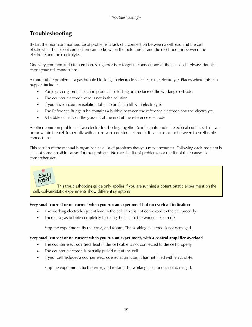
Very small current or no current when you run an experiment but no overload indication
• The working electrode (green) lead in the cell cable is not connected to the cell properly.
• There is a gas bubble completely blocking the face of the working electrode.
Stop the experiment, fix the error, and restart. The working electrode is not damaged.
Very small current or no current when you run an experiment, with a control amplifier overload
• The counter electrode (red) lead in the cell cable is not connected to the cell properly.
• The counter electrode is partially pulled out of the cell.
• If your cell includes a counter electrode isolation tube, it has not filled with electrolyte.
Stop the experiment, fix the error, and restart. The working electrode is not damaged.
This troubleshooting guide only applies if you are running a potentiostatic experiment on the
cell. Galvanostatic experiments show different symptoms.
Troubleshooting--
20
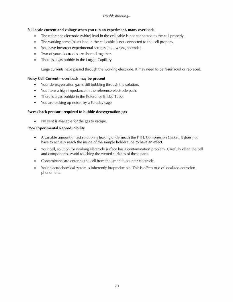
Full-scale current and voltage when you run an experiment, many overloads
• The reference electrode (white) lead in the cell cable is not connected to the cell properly.
• The working sense (blue) lead in the cell cable is not connected to the cell properly.
• You have incorrect experimental settings (e.g., wrong potential).
• Two of your electrodes are shorted together.
• There is a gas bubble in the Luggin Capillary.
Large currents have passed through the working electrode. It may need to be resurfaced or replaced.
Noisy Cell Current—overloads may be present
• Your de-oxygenation gas is still bubbling through the solution.
• You have a high impedance in the reference electrode path.
• There is a gas bubble in the Reference Bridge Tube.
• You are picking up noise: try a Faraday cage.
Excess back pressure required to bubble deoxygenation gas
• No vent is available for the gas to escape.
Poor Experimental Reproducibility
• A variable amount of test solution is leaking underneath the PTFE Compression Gasket. It does not
have to actually reach the inside of the sample holder tube to have an effect.
• Your cell, solution, or working electrode surface has a contamination problem. Carefully clean the cell
and components. Avoid touching the wetted surfaces of these parts.
• Contaminants are entering the cell from the graphite counter electrode.
• Your electrochemical system is inherently irreproducible. This is offten true of localized corrosion
phenomena.
Specifications--
21
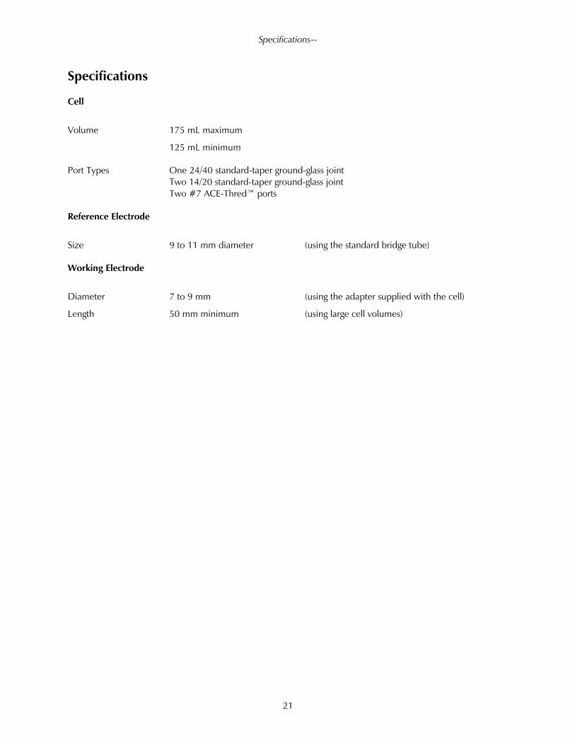
Specifications
Cell
Volume 175 mL maximum
125 mL minimum
Port Types One 24/40 standard-taper ground-glass joint
Two 14/20 standard-taper ground-glass joint
Two #7 ACE-Thred™ ports
Reference Electrode
Size 9 to 11 mm diameter (using the standard bridge tube)
Working Electrode
Diameter 7 to 9 mm (using the adapter supplied with the cell)
Length 50 mm minimum (using large cell volumes)

--
22
Index
Alabama Specialty Products, 1
assembly, 5
basic, 2
bridge, 12
cage, 18
cell connections, 18
chemical, 2
circulating, 1
counter, 10
damage, 3
deaeration, 7
electrode connections, 18, 19
Faraday cage, 18
gas, 7, 8
green and blue cell leads, 18
ground glass joints, 6
jacketed, 1
nitrogen, 7
noise, 18
parts list, 4
platinum, 11
polyethylene, 2
problems, iv
purging, 7
red cell leads, 18
reference electrode lead, 18
replacement of glass frit, 14
sample holder, 15
sample preparation, 15
shipping damage, 3
PTFE compression gasket, 15
temperature, 1
vacuum grease, 6
vent, 9
VistaShield, 8
warranty, ii