european commission directorate-general home a airs · european commission directorate-general home...
TRANSCRIPT

European Commission
Directorate-General Home Affairs
Prevention, Preparedness and Consequence Management of Terrorismand other Security-related Risks Programme
HOME/2009/CIPS/AG/C2-050i-Code: Real-time Malicious Code Identification
Deliverable D3: Integration and Pilot Operation
Workpackage: WP3: Integration and Pilot OperationContractual delivery date: June 2012Actual delivery date: July 2012Deliverable Dissemination Level: PublicEditor Alessandro Frossi (POLIMI)Contributors All PartnersInternal Reviewers: FORTH
Executive Summary: This deliverable is a technical report on the integration
of the different detection and analysis subsystems, and the test operations of the
unified i-Code system.
With the support of the Prevention, Preparedness and Consequence Management ofTerrorism and other Security-related Risks Programme. European Commission -
Directorate-General Home Affairs†.
†This project has been funded with the support of the Prevention, Preparedness and Consequence Manage-
ment of Terrorism and other Security-related Risks Programme of European Commission - Directorate-GeneralHome Affairs. This publication reflects the views only of the author, and the Commission cannot be held re-sponsible for any use which may be made of the information contained therein.

www.icode-project.eu 2 July 16, 2012

Contents
1 Introduction 7
2 Architectural Overview 9
2.1 General design . . . . . . . . . . . . . . . . . . . . . . . . . . 9
2.2 Components . . . . . . . . . . . . . . . . . . . . . . . . . . . . 10
2.2.1 Console . . . . . . . . . . . . . . . . . . . . . . . . . . 10
2.2.2 AccessMiner . . . . . . . . . . . . . . . . . . . . . . . 12
2.2.3 Argos . . . . . . . . . . . . . . . . . . . . . . . . . . . 12
2.2.4 Nemu . . . . . . . . . . . . . . . . . . . . . . . . . . . 13
2.2.5 Anubis . . . . . . . . . . . . . . . . . . . . . . . . . . . 13
3 Integration 15
3.1 Console . . . . . . . . . . . . . . . . . . . . . . . . . . . . . . 15
3.1.1 Prelude Back-end . . . . . . . . . . . . . . . . . . . . . 15
3.1.2 Correlation Rules . . . . . . . . . . . . . . . . . . . . . 16
3.1.3 Console Virtual Machine . . . . . . . . . . . . . . . . . 18
3.2 AccessMiner . . . . . . . . . . . . . . . . . . . . . . . . . . . . 19
3.2.1 Model Enforcement . . . . . . . . . . . . . . . . . . . 19
3.2.2 Threat Model . . . . . . . . . . . . . . . . . . . . . . . 19
3.2.3 Technology Overview . . . . . . . . . . . . . . . . . . 20
3.2.4 Hypervisor Architecture . . . . . . . . . . . . . . . . . 20
3.2.5 System Call Tracer . . . . . . . . . . . . . . . . . . . . 21
3.2.6 Process Revealer . . . . . . . . . . . . . . . . . . . . . 21
3.2.7 Policies Checker . . . . . . . . . . . . . . . . . . . . . 22
3.2.8 Prelude Integration . . . . . . . . . . . . . . . . . . . . 22
3.3 Argos . . . . . . . . . . . . . . . . . . . . . . . . . . . . . . . 23
3.3.1 Client Integration . . . . . . . . . . . . . . . . . . . . 23
3.3.2 Payload Analysis Integration . . . . . . . . . . . . . . 24
3

CONTENTS
3.3.3 Prelude Integration . . . . . . . . . . . . . . . . . . . . 243.3.4 Argos Virtual Machine . . . . . . . . . . . . . . . . . . 24
3.4 Nemu . . . . . . . . . . . . . . . . . . . . . . . . . . . . . . . 243.4.1 Prelude Integration . . . . . . . . . . . . . . . . . . . . 243.4.2 Nemu Virtual Machine . . . . . . . . . . . . . . . . . . 25
3.5 Anubis . . . . . . . . . . . . . . . . . . . . . . . . . . . . . . . 253.6 Events . . . . . . . . . . . . . . . . . . . . . . . . . . . . . . . 25
4 Testing phase 274.1 Testbed Architecture . . . . . . . . . . . . . . . . . . . . . . . 27
4.1.1 Exposure Virtual Machine . . . . . . . . . . . . . . . . 294.2 Event Triggering . . . . . . . . . . . . . . . . . . . . . . . . . 31
4.2.1 Shellcode Choice . . . . . . . . . . . . . . . . . . . . . 324.2.2 Vulnerability Exploitation . . . . . . . . . . . . . . . . 32
4.3 Deployment in Real-World Networks . . . . . . . . . . . . . . 36
www.icode-project.eu 4 July 16, 2012

List of Figures
2.1 Design overview of the i-Code system. . . . . . . . . . . . . . 102.2 Overall architecture of i-Code console. . . . . . . . . . . . . . 11
3.1 Sensor registration procedure . . . . . . . . . . . . . . . . . . 16
4.1 i-Code testbed architecture. . . . . . . . . . . . . . . . . . . . 284.2 Exposure virtual machine with IceCast2 server running. . . . 304.3 Metasploit console with icecast header module . . . . . . . . 334.4 Metasploit icecast header options . . . . . . . . . . . . . . . . 334.5 i-Code console reacting to Nemu alert in the first testing sce-
nario. . . . . . . . . . . . . . . . . . . . . . . . . . . . . . . . 344.6 Shellcode submission to Anubis in the first scenario. . . . . . 344.7 Issuing a read operation on monitored folder. . . . . . . . . . 344.8 Issuing a write operation on monitored folder. . . . . . . . . . 354.9 i-Code console reacting to AccessMiner alert in the first test-
ing scenario. . . . . . . . . . . . . . . . . . . . . . . . . . . . . 354.10 Detailed report popup for AccessMiner’s events. . . . . . . . . 35
5

LIST OF FIGURES
www.icode-project.eu 6 July 16, 2012

CHAPTER 1
Introduction
The i-Code project aims to detect and analyze malicious code and Internetattacks in real time. Its scope includes the detection of attacks in the net-work and on the host, the analysis of the malicious code, and post-attackforensics. Thus, the project takes on challenges from different aspects ofoperational security and proposes to address them with a number of noveldetection and analysis tools. Due to the variety of the tasks they face, thesetools are very diverse, but they can be interconnected to provide an enrichedunderstanding of security incidents, by means of the i-Code console.
Deliverable D1: System Design described the design of each i-Code de-tection and analysis component. Furthermore, the potential synergies be-tween these components were explored. In deliverable D2: System Imple-mentation, then, we reported the actual implementation of the tools and theconsole carried out the project partners and the first steps taken towardsthe final system integration.
In this document we continue from there, going through all the singletools’ integration processes to finally build a comprehensive system havingthe console as its only interface to the external world. We also describe thetesting phase of the i-Code system, which represents its pilot operation.
Outline In this document we detail the integration process of all the com-ponents into a single system. In Chapter 2, we describe the general archi-tecture of the system, going through a short overview of the componentsinvolved in the process and how they fit into the big picture. Chapter 3dwells into the details of how each tool is integrated with the each other,showing how the information about security threats is collected, saved intoevents and dispatched to the manager, before being shown to the final user.
7

CHAPTER 1. INTRODUCTION
Chapter 4, finally, shows the results of this integration process with thedetailed description of the architecture and procedures used in the pilotoperation.
www.icode-project.eu 8 July 16, 2012

CHAPTER 2
Architectural Overview
2.1 General design
The i-Code project aims at detecting and analyzing malicious code andInternet attacks in real time. This is not, however, the only scope of theproject: it also aims at creating an easy and centralized way to show theresults of those tasks. Therefore, it’s not all about the tools that representthe “core” of the system; they are, obviously, a big part of the system itself,but great importance has to be given to the integration of these componentsinto a bigger picture: a comprehensive system capable of detecting threatsin real-time and present them to the user on a single collector application.The advantage is clear: the user doesn’t have to directly use the single toolsand interpret their results (often presented in custom formats) but ratheruse the console application to have all the security alerts collected and shownin an easy-to-read format.
The general design is shown in Figure 2.1. All the sensors deployedwithin the target network (i.e., AccessMiner, Argos and Nemu) raise alertswhenever they detect a security threat and dispatch an event towards theconsole, giving detailed information about the threat itself. When the con-sole receives an alert, it saves it to make it persistent and sends the attachedshellcode to a remote installation of Anubis, which further analyzes it giv-ing back a report identifier. The user is then presented via web interfacethe events (in tabular form) and, following a link to Anubis, the previouslycreated report.
In Section 2.2 a more detailed view of the single components is presented,while Chapter 3 we will go in detail into the integration process.
9

CHAPTER 2. ARCHITECTURAL OVERVIEW
Figure 2.1: Design overview of the i-Code system.
2.2 Components
2.2.1 Console
This component, though not being “active” within the system (it doesn’traise events or detect threats), has a fundamental role in i-Code project: ithas to gather all the relevant events generated by the peripheral sensors andshow them to the user in an understandable and usable way. It is, therefore,the main component in the integration process, since it is the end-point ofany communication from and to the system: all the tools are supposed tosend their alerts to the console which, in turn, is responsible of sending theshellcodes to Anubis, receiving the corresponding report id and showing thealerts to the final user (see Figure 2.1).
Figure 2.2 shows the overall architecture of the i-Code console: the front-end is a simple web application whose task is to simply show the user theresult of the event analysis process performed by the back-end component.Here, in fact, the alerts are received and stored in a database; when theuser accesses the web application, then, they are retrieved and sent to thefront-end along with some useful statistics and additional information.
The console was built to be:
www.icode-project.eu 10 July 16, 2012

2.2. COMPONENTS
Figure 2.2: Overall architecture of i-Code console.
www.icode-project.eu 11 July 16, 2012
CHAPTER 2. ARCHITECTURAL OVERVIEW
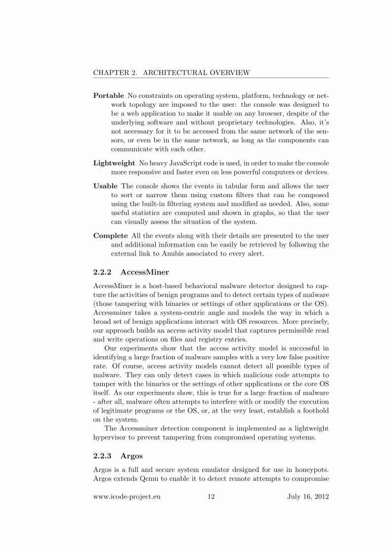
Portable No constraints on operating system, platform, technology or net-work topology are imposed to the user: the console was designed tobe a web application to make it usable on any browser, despite of theunderlying software and without proprietary technologies. Also, it’snot necessary for it to be accessed from the same network of the sen-sors, or even be in the same network, as long as the components cancommunicate with each other.
Lightweight No heavy JavaScript code is used, in order to make the consolemore responsive and faster even on less powerful computers or devices.
Usable The console shows the events in tabular form and allows the userto sort or narrow them using custom filters that can be composedusing the built-in filtering system and modified as needed. Also, someuseful statistics are computed and shown in graphs, so that the usercan visually assess the situation of the system.
Complete All the events along with their details are presented to the userand additional information can be easily be retrieved by following theexternal link to Anubis associated to every alert.
2.2.2 AccessMiner
AccessMiner is a host-based behavioral malware detector designed to cap-ture the activities of benign programs and to detect certain types of malware(those tampering with binaries or settings of other applications or the OS).Accessminer takes a system-centric angle and models the way in which abroad set of benign applications interact with OS resources. More precisely,our approach builds an access activity model that captures permissible readand write operations on files and registry entries.
Our experiments show that the access activity model is successful inidentifying a large fraction of malware samples with a very low false positiverate. Of course, access activity models cannot detect all possible types ofmalware. They can only detect cases in which malicious code attempts totamper with the binaries or the settings of other applications or the core OSitself. As our experiments show, this is true for a large fraction of malware- after all, malware often attempts to interfere with or modify the executionof legitimate programs or the OS, or, at the very least, establish a footholdon the system.
The Accessminer detection component is implemented as a lightweighthypervisor to prevent tampering from compromised operating systems.
2.2.3 Argos
Argos is a full and secure system emulator designed for use in honeypots.Argos extends Qemu to enable it to detect remote attempts to compromise
www.icode-project.eu 12 July 16, 2012

2.2. COMPONENTS
the emulated guest operating system. Using dynamic taint analysis it tracksnetwork data throughout execution and detects any attempts to use themin an illegal way. When an attack is detected, a footprint of the attack islogged that includes a possible payload injected by the attacker.
For the i-Code project, Argos is extended and deployed as a client-sidehoneypot that detects if websites, visited by clients inside the network, at-tempt to compromise visitors.
2.2.4 Nemu
Nemu is a network-level attack detector based on code emulation. The prin-ciple behind its detection approach is that the machine code interpretationof arbitrary data results to random code which, when it is attempted to runon an actual CPU, usually crashes soon, e.g., due to the execution of anillegal instruction. In contrast, if some input contains actual shellcode, thenthis code will run normally, exhibiting a potentially detectable behavior.
Nemu is built around a CPU emulator that executes valid instructionsequences found in the inspected input. Each input is mapped to an ar-bitrary location in the virtual address space of a supposed process, and anew execution begins from each and every byte of the input, as the posi-tion of the first instruction of the shellcode is unknown and can be easilyobfuscated. The detection engine is based on multiple heuristics that matchruntime patterns inherent in different types of shellcode. During execution,the system checks several conditions that should all be satisfied in order fora heuristic to match some shellcode.
All heuristics are evaluated in parallel and are orthogonal to each other,which means that more than one heuristic can match during the executionof some shellcode, giving increased detection confidence. For example, someheuristics match the decryption process of polymorphic shellcode, while oth-ers match operations found in plain shellcode. Polymorphic shellcode usuallycarries an encrypted version of a plain shellcode, so the execution of a poly-morphic shellcode usually triggers both self-decrypting and plain shellcodeheuristics.
2.2.5 Anubis
Anubis is a dynamic malware analysis system that is based on an instru-mented Qemu emulator. It is offered as an open service through a publicwebsite, where users can submit binaries for analysis and receive reportsthat describe the system- and network-level behavior of the analyzed bina-ries in a human-readable way. For the i-Code project, Anubis was extendedto support the analysis and classification of shellcode.
www.icode-project.eu 13 July 16, 2012

CHAPTER 2. ARCHITECTURAL OVERVIEW
www.icode-project.eu 14 July 16, 2012

CHAPTER 3
Integration
3.1 Console
The console is the main integration point of the i-Code system since it’sthe only one that will be shown to the user and will take care of all thecommunication between the user and the peripheral components. Its archi-tecture was accurately described in deliverable D2: System Implementationso, in this Section, only some components will be further detailed to givethe reader an insight on how the single part of the tool cooperate to makethe integration more smooth.
3.1.1 Prelude Back-end
The Prelude server is the real focus point of the whole integration; thiscomponent is responsible of:
• receiving the alerts from the tools
• storing all the information in a local database
• attaching geographical information to each event
• sending the shellcodes (attached to the events) to Anubis
Since this server handles all the relevant information passing throughthe system, it is crucial that it is correctly built and configured keepingsecurity as a first requisite. The database, in fact, is local and not accessibleby processes not running on the console virtual machine; the password,also, is known to the Prelude instance and to the working plugins only. Toincrease security between the sensors and the server, the sensor registration
15

CHAPTER 3. INTEGRATION
(a) Sensor side (b) Server side
Figure 3.1: Sensor registration procedure
process (shown in Figure 3.1) requires the interaction of both parties: theserver listens for new registration requests and creates a one-time passwordto be used as confirmation; the client, instead, generates a 2048 bit RSAkey to encrypt communications and requires the user to provide that samepassword given by the server; this ensures that a human operator is takingcare of registering a known sensor.
When a sensor raises an alert (see tools’ related Sections to know how anevent is created and sent), it is sent to the Prelude Manager process runningon the console machine. This process saves the alert in the database in afully normalized form (which also results difficult to be accessed by a humanoperator) and, at the same time, it forwards it to the registered and enabledplugins. While there are many built-in plugins bundled with Prelude, noneof them was used since they provide functionalities not relevant to the i-Code system; two custom scripts, instead, were created and registered (seeSection 3.1.2 for details). Each script receives as input every alert receivedby the manager and performs on them the small task it is designed for: thiscan be the modification of the alert (or any field) or the creation of a newcorrelated alert, which will be sent to the manager and treated as any othernew event.
When the front-end needs to show the events to the user, it uses acustom script to retrieve them directly from the database, without creatingunnecessary load on the manager.
3.1.2 Correlation Rules
Correlation rules (or plugins) are scripts that are registered on the managerto be eligible to have all the events forwarded and made accessible to them.
www.icode-project.eu 16 July 16, 2012

3.1. CONSOLE
Their task is to perform some minor operations on such events (e.g., checkingif the source address is in some specified networks) and, if necessary, raiseadditional events to the manager. This is particularly useful when dealingwith contexts: if, for example, 10 login failed events are detected in a 3minutes period, a new Possible Brute Force event can be raised by a rule.
As said in Section 3.1.1, no built-in rules were used since they imple-mented functionalities that were not needed by the i-Code system. Twoadditional custom rules, instead, were created and registered. These plug-ins, however, deviate from the standard plugin design: they do not createadditional events but rather modify incoming events; this is not usually al-lowed, anyway, because in a standard Prelude deployment all the eventshave to be securely stored in the database and cannot be modified.
In our case, however, the goal of the two plugins is to augment the in-formation contained in the event and it is, therefore, necessary to modify itafter being stored in the database. Since there’s no API provided by Preludefor this (while there is for context manipulation and event creation), we hadto do it manually: when a tool creates an alert, it stores a beacon in eachadditional field: this beacon is simply a random string that will be substi-tuted by the new information once the alert is delivered to the correlationrule. This trick was made necessary because the information stored in thedatabase is fully normalized and fragmented over many tables: retrievingthe entire field set for an event is not a simple matter of joining some tablesbut requires a much greater effort; the use of random beacons (long enoughto avoid unfortunate collisions) allows to pin-point the interesting data inthe database and modify it in a completely transparent way.
Source IP Geolocation Plugin
The Source IP Geolocation Plugin uses the event source IP to geographicallylocate the origin of the security threat.
The address contained in the alert.source(0).node.address(0).address fieldof the IDMEF event (see Section 3.6) translated into a country code: thecountry from where the packet was sent. Once this information is available,the plugin looks for the corresponding beacon in the additional data tableand substitutes it with the correct information.
In this way, the information is added to the alert, instead of creating abrand new one.
Anubis Submitter Plugin
The Anubis Submitter Plugin is the real integration point between the i-Code system and the remote Anubis application. It works just like theSource IP Geolocation Plugin: it retrieves the relevant information from the
www.icode-project.eu 17 July 16, 2012

CHAPTER 3. INTEGRATION
alert, uses it to collect new additional data and stores these new informationin the alert itself by modifying the beacon in the database.
The relevant piece of data, however, is not the source address, but ratherthe shellcode associated to the detected security threat; as described inSection 3.6, in fact, each tools attaches the attack shellcode (encoded inbase64) to the IDMEF alert in the alert.additional data(2).data field. Thisis then sent to Anubis via the Python script provided on the website1 andthe resulting report ID is written on the database in place of the beaconsaved in the alert.additional data(1).data field.
The result is that this plugin allows to further analyze the shellcode andretrieve the corresponding report directly from the Anubis website.
3.1.3 Console Virtual Machine
All the softwares that are part of the console component in the i-Code systemare hosted on the same virtual machine. This choice was made for two mainreasons:
• keeping all the components on the same machine does not require themto be accessible by processes running on other machines. Obviously,both the Prelude server and the web server have to be accessible fromoutside, but at least there is no need to expose the database and opena possible security hole. It would be, however, possible to host thedatabase or any other component (e.g. the Prelude Correlator tool)on other machines to balance the load on the console
• for testing purposes the system was not stressed enough to make astrong load-balancing a necessity: the frequency of incoming alertswas low enough to keep the Prelude server and the database far undertheir capacity limits.
There were no particular hardware requisites so a single core machinewith 1 Gb RAM was instantiated. The operating system is the one thatoffers both the maximum compatibility with the Prelude software (withpre-compiled packages offered by standard repositories) and easiness of use:Ubuntu Desktop 11.10 64-bit. The only packages needed to make the consolework were the following:
Prelude Libraries The libraries necessary to make the Prelude architec-ture work: they handle all the communications between the managerand the sensors, including cryptography and heartbeats.
Prelude Manager This is the software component that receives all theevents from the peripheral sensors. It relies on the above libraries
1http://shellcode.iseclab.org/Resources/submit_to_anubis.py
www.icode-project.eu 18 July 16, 2012

3.2. ACCESSMINER
and a storage connector, which, in our case, is a MySQL databaseconnector; the latter is in charge of writing and reading data from thenon-volatile storage.
MySQL Database The DBMS used to save all the alerts: it does not haveto be exposed to external connections because it is always accessed bylocal processes: the manager, the web application back-end and thecorrelation rules.
Prelude Correlator This software registers and runs the Geolocation andAnubis Submitter plugins: it is registered as a sensors with “forward”permissions on the manager, which means that every alert receivedby the Prelude system is sent immediately to the rule chain in thecorrelator. This component has also direct access to the database tomodify the events adding useful information.
Python + Flask The back-end logic and the front-end web applicationare both written using the Flask framework for Python, which is lightenough for the console application.
3.2 AccessMiner
The model enforcement component of AccessMiner was redesigned to in-crease its security by moving it at the hypervisor level. In addition, Ac-cessMiner was extended with a new module to communicate to the preludesystem. These modifications are explained in the rest of the section.
3.2.1 Model Enforcement
Our new enforcement model exploits the hardware virtualization supportavailable in commodity x86 CPU. By using the VMM extensions we designeda tamper-resistant detector that is able to control OS operations and verifythe policies derived from the AccessMiner system.
3.2.2 Threat Model
The threat model under which our enforcement model runs considers a verypowerful attacker. The attacker can operate with kernel-level privileges. Onthe other side the attacker cannot perform hardware-based attacks (e.g., aDMA-based attack) and he cannot tamper the hypervisor operations. Weassume that our hypervisor starts during the boot process of the machineand it is the privilegest hypervisor on the system.
www.icode-project.eu 19 July 16, 2012

CHAPTER 3. INTEGRATION
3.2.3 Technology Overview
Before describing how our detector works we give a brief introduction aboutIntel virtualization.
The main characteristic of Intel VT-x technology is supporting new VMXmode of operation. When in VMX mode, the processor can be either VMXroot or VMX non-root operation. The behavior of the processor in VMXroot operation is similar to the one that operates in normal mode expectof using a new set of instructions called VMX instructions. The behaviorof the processor in non-root operation is limited in terms of controlling theaccess to the resources even when the CPU is running in ring 0 (highestprivilege).
The VMM can monitor operations on critical resources without mod-ifying the code of the guest OS. Moreover because VMX non-root modeoperation includes all four IA-32 privileges levels (rings) guest software canrun in the original rings in where designed to be run.
A processor which has been turned on in a normal mode can be madeto enter VMX root operation by executing vmxon operation. The virtualmachine monitor VMM running in root operation sets up the environmentand initiates the virtual machine by executing vmlaunch instruction.
When a VMM is running, the CPU switches back and forth betweennon-root and root mode: the execution of the virtual machine might beinterrupted by an exit (VMexit) to root mode and subsequently resumed byan enter to non-root mode (VMentry).
The technology provides a data structure called the VMCS (virtual ma-chine control structure) that embeds all the information needed to capturethe state of the virtual machine or resume the virtual machine. The var-ious control fields determine the conditions under which control leaves thevirtual machine (VMexit) and returns to the VMM, and define the actionsthat need to be performed during VM entry and VM exit.
Various events cause the processor to leave control to VMM in rootoperation. The processor can also exit from the virtual machine explicitlyby executing vmcall instruction. In particular, for our detector model we areinterested to exploit the vmcall instruction for intercepting the system callevent. More details about the technique are explained in the next sections.
3.2.4 Hypervisor Architecture
The new Detector model is composed by three components: System callInterceptor, Process Revelear and Policies Checker. The outputs of all thecomponents are combined together to check the policies derived by Access-Miner system.
www.icode-project.eu 20 July 16, 2012

3.2. ACCESSMINER
3.2.5 System Call Tracer
The core of the system is represented by System Call Tracer. In orderto intercept the system call we monitor the sysenter/systexit instructions.Whenever a system call is issued by a process a sysenter instruction is in-voked. The sysenter instruction refers to the MSR register that contains theSYSENTER EIP, the instruction pointer that will point to a small stub thathandles the invocation of the appropriate system call handler. When thesystem call handler is terminated the control flow execution returns into thestub, at this point sysexit instruction is issued and the control-flow returnsto the user space application.
In order to bring the execution flow inside the hypervisor we need toswitch from VMX non-root mode to VMX root mode. To this end we sub-stituted the SYSENTER EIP value into the MSR register in order to pointto the vmcall instruction. By using this hooking technique the hypervisor isable to intercept every sysenter and sysexit performed on the system. Whena sysenter is invoked the hooking code intercepts the control-flow and parsesthe parameters according to the sort of the operation. Before sending theinformation to the Policies Checker, the system needs to check the successfulexecution of the operation and the return values (sysexit interception). Incase the operation fails, the component does not produce any output. In theother case, the System Call Tracer invokes the Policies Checker componentand it provides all the system call information: system call type, parameters,and return values.
3.2.6 Process Revealer
Another important information that we need to provide to the PoliciesChecker is the name of the process. To this end we utilize a cache systemthat is able to associated the CR3 value to the process’s name. In particularevery time a process is created or destroyed the system updates the processcache with the new information (CR3, process). From technical point ofview we utilize the same interception technique deployed for System CallTracer. In particular the system intercepts the sysexit for create/terminateprocess operation and queries the EPROCESS structure in order to obtainthe association between the process’s name and the CR3 value. The Pro-cess Revealer component will update the cache information accordingly. Itis important to note the cache memory system can speed up our detectionmechanism since the Policies Checker needs the information CR3, processname for applying the policies rules. Without cache system, every time asystem call is invoked, the Policies Checker should query the EPROCESSstructure and retrieves this information. In case of using the cache systemthe information can be obtained in constant time (e.g, hash table).
www.icode-project.eu 21 July 16, 2012

CHAPTER 3. INTEGRATION
3.2.7 Policies Checker
The main goal of this component is to check the policies derived from the Ac-cessMiner system and creates an alert in case some of them are violated. Inparticular, in order to check the policies we deployed an hash table memorystructure where the resources name (files pathname, registries pathname)is the key of the hash table and the element is represented by the name ofthe processes with their own permission on the resources. We recognize twomain phases for the Policies Checker: Initialization and Detection Phase.The initialization phase occurs after the loading of the hypervisor kernelmodule. The main task of such a phase is to initialize the memory struc-tures that will be used for the detection phase. The phase works as follows.First the Hypervisor Kernel Module reads the signatures from a configu-ration file. Then, whenever a signature is loaded the full-pathname of theresources is extracted and utilize as a key of the hash table in order to storethe following information: the list of the processes that can get access tothe resources and their own access permissions on that resources.
After the initialization of the hash memory structure a memory handlesstructure is created. This memory structure is used in order to track downthe different operations on the resources (e.g., files and registries) by lookingup the full-pathname and the resource handle. In particular every time aresource is opened we track down the handle associated to the resource full-pathname and we store it in the memory structure. After wards when someoperations occurs on the resource we link the resource full-pathname to thehandle and we pass this information to the detection module. Every timean handle is closed we remove it from the list.
During the detection phase, The System Call Tracer invokes the PoliciesChecker and sends the system call information. At this point the PoliciesChecker by using the full pathname as the key of the hash table it retrievesthe list of the processes and the resource access permissions. It also queriesthe process cache in order to get the process’s name that performed thesystem call. When obtained all the information it scans the list of theprocesses for searching the actual process name. If the process name isfound, the Policies Checker checks the permission associated to it and ifthere’s a mismatch with the permission it reports a warning. If the processis not present in the process list the Policies Checker reports a warning tothe system as well. In the other cases it does nothing.
3.2.8 Prelude Integration
Whenever a warning is produced the detector system sends the output ofthe warning to the serial port where a receiver (python server) is in chargeto decode the message according to the Prelude standard format and sendit back to the console. The Prelude standard format contains 8 fields with
www.icode-project.eu 22 July 16, 2012
3.3. ARGOS
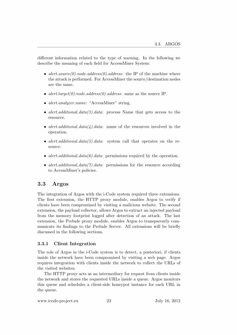
different information related to the type of warning. In the following wedescribe the meaning of each field for AccessMiner System:
• alert.source(0).node.address(0).address: the IP of the machine wherethe attack is performed. For AccessMiner the source/destination nodesare the same.
• alert.target(0).node.address(0).address: same as the source IP.
• alert.analyzer.name: “AccessMiner” string.
• alert.additional data(3).data: process Name that gets access to theresource.
• alert.additional data(4).data: name of the resources involved in theoperation.
• alert.additional data(5).data: system call that operates on the re-source.
• alert.additional data(6).data: permissions required by the operation.
• alert.additional data(7).data: permissions for the resource accordingto AccessMiner’s policies.
3.3 Argos
The integration of Argos with the i-Code system required three extensions.The first extension, the HTTP proxy module, enables Argos to verify ifclients have been compromised by visiting a malicious website. The secondextension, the payload collector, allows Argos to extract an injected payloadfrom the memory footprint logged after detection of an attack. The lastextension, the Prelude proxy module, enables Argos to transparently com-municate its findings to the Prelude Server. All extensions will be brieflydiscussed in the following sections.
3.3.1 Client Integration
The role of Argos in the i-Code system is to detect, a posteriori, if clientsinside the network have been compromised by visiting a web page. Argosrequires integration with clients inside the network to collect the URLs ofthe visited websites.
The HTTP proxy acts as an intermediary for request from clients insidethe network and stores the requested URLs inside a queue. Argos monitorsthis queue and schedules a client-side honeypot instance for each URL inthe queue.
www.icode-project.eu 23 July 16, 2012

CHAPTER 3. INTEGRATION
3.3.2 Payload Analysis Integration
The i-Code system has the capability of submitting payloads to Anubis forin-depth threat analysis. This capability of the i-Code system requires apayload to be a base64 encoded binary blob.
The memory footprint logged by Argos contains the required informa-tion, but in a different format. The payload extractor module is able tofind a payload inside this footprint, by using information collected duringthe attack, and extract it. Finally, after a successful extraction the payloadmodule returns a base64 encoded payload.
3.3.3 Prelude Integration
For the integration with Prelude, Argos is extended with a Prelude proxy.The proxy model allows for transparent scaling of capacity if required by anincrease or decrease of client requests. The Prelude proxy acts a client tothe Prelude Manager and is responsible for transparently forwarding eventsfrom Argos using the IDMEF format, as defined in deliverable D2: SystemImplementation.
3.3.4 Argos Virtual Machine
The virtual machine is configured to run the aforementioned HTTP proxyand Prelude proxy, as well as a Argos driver and a single Argos instance.
The Argos driver is responsible for orchestrating the website verificationprocess. For each URL collected by the HTTP proxy, the Argos driverschedules an Argos instance, configured as a client-side honeypot, and directsit to the website that requires verification. In the test phase the Argos driverschedules only one Argos instance, but the pool of Argos instances can bescaled linearly by distributing multiple instances over multiple servers.
In case of an attack detection, the Argos driver obtains the collectedinformation from the Argos instance and invokes the payload collector tofind an injected payload. When the payload collector finishes, the Argosdriver submits everything to the Prelude proxy server, which sends an eventto the Prelude Manager.
3.4 Nemu
3.4.1 Prelude Integration
As part of the i-Code system, Nemu was extended with a new module thatacts as a client for the Prelude manager and submits to it all detectedevents. For each attack, Nemu stores in a local SQLite database all therelevant information, such as the date and time of the incident, the sourceand destination IP address and port, the type of the identified shellcode and
www.icode-project.eu 24 July 16, 2012

3.5. ANUBIS
its execution trace, MD5 sums of the shellcode and the stream chunk thatcontained it, and other details. It also extracts the raw shellcode from theinput stream and stores it into a separate file for further analysis.
For performance and modularity, Nemu’s Prelude client module runs asa separate process, and does not require any form of communication withthe actual Nemu detector. This is achieved by relying only on Nemu’s lo-cal database for retrieving new incident alerts. The client module monitorsfor changes in Nemu’s database using Pyinotify, a Python module for mon-itoring filesystem events. Whenever a new record is written in the main“alerts” table in the database, the module is triggered and pulls the neces-sary information for submission to the Prelude manager. It then constructsan IDMEF message according to the format specified in deliverable D2:System Implementation, and transmits it to the Prelude manager. All therelevant info is retrieved from the database, except the extracted shellcode,which is read directly from its own file. The shellcode is included in thefield alert.additional data(2).data of the IDMEF message in base64encoding for subsequent analysis by Anubis, as described in Section 3.6.
3.4.2 Nemu Virtual Machine
Nemu is running on a separate virtual machine, and monitors all trafficreaching the main network interface, which is set to promiscuous mode.Nemu has been configured to scan both directions of each connection, soas to detect both client-side and server-side attacks. All attack incidentsare logged in the local database, and are then transmitted to the Preludemanager by Nemu’s Prelude client module, which also runs on the samevirtual machine.
3.5 Anubis
The Anubis malware analysis sandbox for analyzing shellcodes is deployedat TUV and is accessed through a public website2. Additionally, a Pythonscript facilitates the automatic submission of shellcodes. For each successfulsubmission of a shellcode, Anubis returns a unique report ID, with whichthe analysis report can be retrieved, once the analysis is finished.
3.6 Events
The events are the only mean for the sensors to communicate with the man-ager and pass it the information about security threats they detected; theycomply to the Intrusion Detection Message Exchange Format3 (IDMEF)
2http://shellcode.iseclab.org3http://www.ietf.org/rfc/rfc4765.txt
www.icode-project.eu 25 July 16, 2012

CHAPTER 3. INTEGRATION
which defines both data formats and exchange procedures for intrusion de-tection and response systems. The data format offers a skeleton structurefor events but also allows some degrees of freedom in customizing it; in thei-Code system we took this liberty to customize alerts to our need, whichresulted in the structure described in deliverable D2: System Implementa-tion.
The modification that most impacts on the integration process is theaddition of three custom fields besides the standard ones:
alert.additional data(0).data This field will contain the country the sourceIP belongs to. This information, however, is not immediately availablebut will be filled after the alert will be sent to the Source IP Geoloca-tion Plugin (see Section 3.1.2); to ensure that the data will be writtenin the correct event in the database, the sensors save a random stringin this field, leaving it behind as a beacon to allow the correlation ruleto point to the correct record when the source country is available.
alert.additional data(1).data This field is also filled with a random bea-con but the information it is reserved to is different: the Anubis Sub-mitter Plugin, in fact, will use this slot to save the report ID obtainedafter sending the shellcode to the remote installation of Anubis.
alert.additional data(2).data This field contains the base 64 encodedshellcode that was part of the attack and that was detected and savedby the tools. This is the data that will be sent to Anubis for furtheranalysis.
www.icode-project.eu 26 July 16, 2012
CHAPTER 4
Testing phase
This chapter is entirely dedicated to i-Code system testing phase. Section 4.1describes the architecture build to verify if the tools correctly detect andsignal security threats and if the console is able to gather such events andshow them to the user in a fast and easy way.
Section 4.2, instead, shows how the testing phase was conducted in everyaspect. Each step, in fact, is the result of a careful planning aimed atreducing the possible external factors that could compromise the experimentand, at the same time, keeping the attack as close to reality as possible: thismeans that the vulnerable software, the exploit and the deployed shellcodeare not custom and were not coded purposely for this test.
4.1 Testbed Architecture
The testbed for the i-Code system is a purely virtual environment madeof the machines described in Chapter 3. All the tools, exception made forAnubis, are hosted on dedicated machines and connected to each other viaa dedicated LAN network: in fact, while Argos, AccessMiner and Nemu donot rely on external data and computational power, Anubis takes advantageof remotely deployed workers performing the relevant shellcode and malwareanalysis and from previously analyzed samples. As a consequence we decidedto keep Anubis the way it was meant to be since the beginning: a remoteweb service.
This type of architecture was chosen because it has some advantages:
Manageability Keeping the virtual machines in the same environmentmade it faster to deploy them and easier to manage them; the pres-ence of a single entry point for all the configuration needs was also
27

CHAPTER 4. TESTING PHASE
Figure 4.1: i-Code testbed architecture.
beneficial, since the partners don’t have to deal with access and OSpermission issues and could instead focus on integrating the tools.
Network problems resilience During the integration of the entire sys-tem into i-Code the main focus had to be maintained on the devel-opment and debugging of the tools: network problems not directlyrelated to the development phase would have been a source of delaysand would have need additional efforts to be solved. This architecturepartly solves the issue by having a single virtual network to be man-aged and troubleshooted, thus relieving the partners from this burden.
Locality Some of the tools need to work in promiscuous mode and betherefore able to read the traffic originating from and going to othermachines in the system. On a distributed testing environment thisconstraint would have posed some issues on the placement of the ma-chines. This, however, wouldn’t be a problem in a real deploymentsince the sensors would likely be in the same network of the monitoredmachines and not remotely located.
The overall architecture is described in Figure 4.1: there’s a total ofsix virtual machines hosted on a single physical machine, including a VMcreated for testing purposes only (described in Section 4.1.1).
The host is has the following configuration:
Model: HP Z210 Workstation
CPU: Intel® Xeon(R) CPU E31245 @ 3.30Ghz x 4
www.icode-project.eu 28 July 16, 2012

4.1. TESTBED ARCHITECTURE
RAM: 16 Gb
Disk: 1 Tb
OS: Ubuntu Desktop 11.10 64-bit
Environment: VMware® Workstation 8.0.2
Because of some architectural constraints, VMWare Workstation 8 wasused to host the virtual machines: AccessMiner, in fact, relies on nestedvirtualization to run and therefore has to be able to access particular CPUtechnologies even in a virtual environment. For this same reason we alsohad to be sure that the host CPU provided two key features: Extended PageTables (EPT) and Intel Virtualization Technology (VT-x)
Virtual LAN. As said, tools like Nemu had to be able to enter promis-cuous mode to read traffic originating from and going to other virtual ma-chines. Also, to avoid network noise from external machines, the networkhad to be restricted to those guests only. For this reason a virtual LAN wascreated and used for the entire environment and VMWare was set to allowVMs to access promiscuous mode and get traffic not addressed to them.
The only other architectural constraint to fulfill was letting the systemhave access to the Internet to send shellcodes to Anubis and get back theirreport id. In addition, for testing purposes, the vulnerable virtual machine(Exposure) needed Internet access to allow droppers or particular shellcodesto download data from the web to the machine and trigger some specific rulesin the monitoring tools. Therefore both the Console and Exposure machineswere allowed to be NAT ted through the host network connection.
4.1.1 Exposure Virtual Machine
In order to fully test the i-Code system including the peripheral tools, thebest choice would be to deploy the system and wait for some random attack-ers to drop a shellcode onto the vulnerable decoy machine. This, however,would be a time-consuming task, so the next best choice was taken: simulatea real attack on a target machine in the virtual environment.
For this purpose a dedicated VM was created with Windows XP ServicePack 3 as operating system. Instead of exploiting an OS vulnerability,however, we chose a vulnerable software as the target of our testing phase:IceCast2 2.0 1 (see Figure 4.2), a free software for streaming multimedia wasinstalled on Exposure machine. No other software was installed.
The vulnerability that was exploited in IceCast server was a buffer over-flow in the request header, described in CVE-2004-1561 2. Since there’s an
1http://www.icecast.org/2http://www.cvedetails.com/cve/CVE-2004-1561/
www.icode-project.eu 29 July 16, 2012

CHAPTER 4. TESTING PHASE
Figure 4.2: Exposure virtual machine with IceCast2 server running.
www.icode-project.eu 30 July 16, 2012

4.2. EVENT TRIGGERING
existing Metasploit3 module to exploit this vulnerability and drop a shell-code into the vulnerable machine, this vulnerability was the best candidateto test the i-Code system.
In order to test AccessMiner functionalities, its client was installed onthis machine: this is the component responsible of detecting policy violationsand notify them. Also, to avoid noise on the console reducing false positives,a very minimum set of policies was configured; in particular a folder calledvulnfolder was created in the root level of the hard drive and AccessMinerwas configured to grant read permissions and revoke write permissions toall processes for that directory.
Finally, for Argos to work properly, the Argos virtual machine was setas Internet proxy to allow it to intercept all the traffic going from and tothe Exposure VM and identify possible threats.
4.2 Event Triggering
The real testing phase takes place in three different steps:
Shellcode choice The shellcode to be used for the test attack must bechosen carefully since it has to trigger all the tools involved in theprocess, namely Argos, Nemu and AccessMiner. While the first twotools should not have problems in detecting any kind of shellcode goingthrough the network, allowing us to use Metasploit built-in shellcodepayloads, AccessMiner raises alerts on predefined system policy vio-lations. For this reason, we couldn’t use any shellcode but we had tofind one capable of violating such policies.
Vulnerability exploitation Once a suitable shellcode is chosen, the vul-nerability described in Section 4.1.1 has to be exploited in order to beable to deploy the payload and let the tools react to the situation.
Console verification If all the tools correctly react to the shellcode sentto the vulnerable machine, the console must correctly and timely showthe generated alarms.
Test scenario This scenario evaluates how the system reacts to attacklaunched against hosted application: on the Exposure VM is installed a vul-nerable streaming server (IceCast server) answering HTTP requests comingfrom clients outside the network. For this test we pretended the host ma-chine to be an external client and launched the attack against the server,dropped a shellcode and tried to manipulate data on the vulnerable system:both Nemu and AccessMiner reacted to the attack.
3http://www.metasploit.com
www.icode-project.eu 31 July 16, 2012

CHAPTER 4. TESTING PHASE
In the following sections the three phases previously defined will be de-scribed.
4.2.1 Shellcode Choice
The shellcode that was chosen was the one that allowed the highest degreeof freedom on the vulnerable machine and allowed us to know exactly whenthe AccessMiner policies were violated. Therefore, for testing, we used asimple shell bind tcp shellcode, which makes the vulnerable machine spawna shell and connect it to a socket purposely created on the attacker’s side.
As a result, if the exploit was successfully landed, we had full remotecontrol over the Exposure VM and could easily write a file in the directoryconfigured to have only read-permissions, thus trigger AccessMiner.
4.2.2 Vulnerability Exploitation
The icecast header in Metasploit was built to exploit the vulnerability de-scribed in Section 4.1.1 and it was therefore the best choice to deploy ashellcode into the vulnerable machine.
Since the idea was to conduct the attack in realistic condition, as far aspossible, the Metasploit software was not executed on a virtual machine inthe virtual environment but rather on the host machine. No other externalmachines were used, so that no exposure was given to the test environmentallowing external factors to possibly compromise the experiment.
After starting the IceCast2 vulnerable server on the target machine, werun the Metasploit console on the host machine and load the icecast headermodule, as shown in Figure 4.3; we then set the required options for themodule: the only one needed at this point is the RHOST, set to the ExposureVM network address (172.0.0.50) (Figure 4.4).
After loading the payload chosen in Section 4.2.1, the attack is success-fully launched to the vulnerable machine. Nemu should have now detectedthe shellcode going through the network while AccessMiner should have seensome policy violations and therefore raised an alarm. Therefore both Nemuand AccessMiner should have sent security events to the console, which cannow display them on the web application.
4.2.2.1 i-Code Console reaction
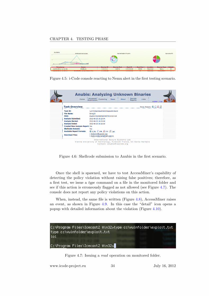
Right after launching the attack, Nemu correctly detects an attack originat-ing from the host machine client (with IP 172.0.0.1 – mapped as “Reserved”– and random port higher than 1024) and aimed at the Exposure VM server(IP 172.0.0.50 and port 8000), as shown in Figure 4.5. Also, the shellcodeis sent to the Anubis server, where the in–depth analysis is immediatelystarted (see Figure 4.6).
www.icode-project.eu 32 July 16, 2012

4.2. EVENT TRIGGERING
Figure 4.3: Metasploit console with icecast header module
Figure 4.4: Metasploit icecast header options
www.icode-project.eu 33 July 16, 2012
CHAPTER 4. TESTING PHASE
Figure 4.5: i-Code console reacting to Nemu alert in the first testing scenario.
Figure 4.6: Shellcode submission to Anubis in the first scenario.
Once the shell is spawned, we have to test AccessMiner’s capability ofdetecting the policy violation without raising false positives; therefore, asa first test, we issue a type command on a file in the monitored folder andsee if this action is erroneously flagged as not allowed (see Figure 4.7). Theconsole does not report any policy violations on this action.
When, instead, the same file is written (Figure 4.8), AccessMiner raisesan event, as shown in Figure 4.9. In this case the “detail” icon opens apopup with detailed information about the violation (Figure 4.10).
Figure 4.7: Issuing a read operation on monitored folder.
www.icode-project.eu 34 July 16, 2012

4.2. EVENT TRIGGERING
Figure 4.8: Issuing a write operation on monitored folder.
Figure 4.9: i-Code console reacting to AccessMiner alert in the first testingscenario.
Figure 4.10: Detailed report popup for AccessMiner’s events.
www.icode-project.eu 35 July 16, 2012

CHAPTER 4. TESTING PHASE
4.3 Deployment in Real-World Networks
The diverse set of detection approaches that comprise the i-Code architec-ture allows it to be adopted to fit different operational needs and deploymentscenarios. As part of the testing phase, two instances of the i-Code systemhave been installed and are operational in real networks.
The first instance has been installed at the University of Crete, andthe second one at the FORTH-ICS. In both deployments, Nemu is usedto scan the traffic that goes through the main gateway that connects eachorganization’s campus to the Internet. Nemu has been configured to scanthe client-to-server data of all established TCP connections, irrespectivelyof the destination port (service). In both cases, all detected attacks aresubmitted to Anubis for further analysis.
Due to the more strict firewall configuration policies that are in place atFORTH-ICS, the number of detected incidents for the past month is aboutthree per week, and are mostly related to non-managed guest devices thatconnect to the local network through the provided public WiFi. In contrast,the more open-access nature of the University network results to servicesbeing exposed to the public Internet, and consequently to a higher numberof attacks against local servers. The number of detected incidents at theUniversity of Crete for the last three months is about two incidents perday.
www.icode-project.eu 36 July 16, 2012