european ets 300 175-3 telecommunication … · ets 300 175-3: september 1996 ... 6.2.2.1 tail...
TRANSCRIPT

EUROPEAN ETS 300 175-3
TELECOMMUNICATION September 1996
STANDARD Second Edition
Source: ETSI TC-RES Reference: RE/RES-03027-3
ICS: 33.060, 33.060.50
Key words: DECT, MAC, radio
Radio Equipment and Systems (RES);Digital Enhanced Cordless Telecommunications (DECT);
Common Interface (CI);Part 3: Medium Access Control (MAC) layer
ETSI
European Telecommunications Standards Institute
ETSI Secretariat
Postal address: F-06921 Sophia Antipolis CEDEX - FRANCEOffice address: 650 Route des Lucioles - Sophia Antipolis - Valbonne - FRANCEX.400: c=fr, a=atlas, p=etsi, s=secretariat - Internet: [email protected]
Tel.: +33 92 94 42 00 - Fax: +33 93 65 47 16
Copyright Notification: No part may be reproduced except as authorized by written permission. The copyright and theforegoing restriction extend to reproduction in all media.
© European Telecommunications Standards Institute 1996. All rights reserved.

Page 2ETS 300 175-3: September 1996
Whilst every care has been taken in the preparation and publication of this document, errors in content,typographical or otherwise, may occur. If you have comments concerning its accuracy, please write to"ETSI Editing and Committee Support Dept." at the address shown on the title page.

Page 3ETS 300 175-3: September 1996
Contents
Foreword ......................................................................................................................................... 13
1 Scope .................................................................................................................................... 15
2 Normative references .............................................................................................................. 15
3 Definitions and abbreviations .................................................................................................... 163.1 Definitions................................................................................................................. 163.2 Abbreviations............................................................................................................ 17
4 Description of the MAC layer.................................................................................................... 194.1 MAC layer reference model ....................................................................................... 19
4.1.1 General ................................................................................................. 204.1.2 Cluster Control Function (CCF)................................................................ 204.1.3 Cell Site Functions (CSF)........................................................................ 204.1.4 Relationship to physical layer elements .................................................... 20
4.2 Frame and multiframe structures ................................................................................ 214.2.1 General ................................................................................................. 224.2.2 Frame structure ..................................................................................... 224.2.3 Multiframe structure................................................................................ 23
4.3 State definitions ........................................................................................................ 244.3.1 PP states .............................................................................................. 244.3.2 RFP states ............................................................................................ 25
5 Overview of MAC layer services............................................................................................... 265.1 General.................................................................................................................... 26
5.1.1 Broadcast Message Control (BMC) ......................................................... 265.1.2 Connectionless Message Control (CMC).................................................. 265.1.3 Multi-Bearer Control ............................................................................... 26
5.2 Service descriptions .................................................................................................. 265.2.1 Common functions.................................................................................. 265.2.2 BMC service .......................................................................................... 275.2.3 CMC service.......................................................................................... 275.2.4 MBC services ........................................................................................ 27
5.3 Logical channels........................................................................................................ 285.3.1 MBC connection endpoints (MC-SAP logical channels).............................. 28
5.3.1.1 The higher layer C-plane channels, C ............................... 285.3.1.2 The higher layer U-Plane channels, I ................................ 285.3.1.3 The higher layer U-Plane control channel, GF.................... 29
5.3.2 CMC endpoints (MB-SAP logical channels) .............................................. 295.3.2.1 The connectionless C-Plane channels, CL......................... 295.3.2.2 The connectionless U-Plane channels, SIN and SIP ........... 29
5.3.3 BMC endpoint (MA-SAP logical channel).................................................. 295.3.3.1 The slow broadcast channel, BS...................................... 29
5.3.4 Internal MAC control channels ................................................................. 295.3.4.1 The system information channel, Q .................................. 305.3.4.2 Identities channel, N........................................................ 305.3.4.3 The MAC control channel, M............................................ 305.3.4.4 MAC paging channel, P................................................... 30
5.4 SAP definitions.......................................................................................................... 305.4.1 MA SAP ................................................................................................ 315.4.2 MB SAP ................................................................................................ 315.4.3 MC SAP ................................................................................................ 315.4.4 ME SAP ................................................................................................ 32
Page 4ETS 300 175-3: September 1996
5.4.5 Order of transmission ............................................................................. 325.5 Bearers .................................................................................................................... 32
5.5.1 Bearer types.......................................................................................... 325.5.2 Bearer operation .................................................................................... 33
5.6 Connection oriented services...................................................................................... 335.6.1 Connection types.................................................................................... 34
5.6.1.1 Basic connections ........................................................... 345.6.1.2 Advanced connections..................................................... 345.6.1.3 Connection identifiers ...................................................... 345.6.1.4 Physical connections ...................................................... 35
5.6.2 Symmetric and asymmetric connections ................................................... 355.6.2.1 Symmetric connections.................................................... 355.6.2.2 Asymmetric connections.................................................. 36
5.7 Broadcast and connectionless services ....................................................................... 385.7.1 The broadcast services........................................................................... 39
5.7.1.1 The continuous broadcast service .................................... 395.7.1.2 The non-continuous broadcast service .............................. 40
5.7.2 The connectionless services .................................................................... 405.7.2.1 Connectionless downlink services..................................... 405.7.2.2 Connectionless uplink services ......................................... 40
6 Multiplexing ............................................................................................................................. 416.1 CCF multiplexing functions.......................................................................................... 416.2 CSF multiplexing functions.......................................................................................... 41
6.2.1 Bit MAPpings (MAP)............................................................................... 476.2.1.1 D-field MAPping (D-MAP)................................................ 476.2.1.2 A-field MAPping (A-MAP)................................................ 486.2.1.3 B-field MAPping (B-MAP)................................................ 49
6.2.2 Time multiplexers.................................................................................... 516.2.2.1 Tail MUltipleXer (T-MUX)................................................. 51
6.2.2.1.1 T-MUX algorithm for RFPtransmissions ..................................... 51
6.2.2.1.2 T-MUX algorithm for PT transmissions . 536.2.2.2 B-field control multiplexer (E/U-MUX)................................ 536.2.2.3 B-field mode multiplexer (C-MUX) .................................... 54
6.2.2.3.1 Double slot and full slot modes ............ 546.2.2.3.2 Half slot modes .................................. 57
6.2.3 Encryption.............................................................................................. 576.2.4 Scrambling............................................................................................. 586.2.5 Error control........................................................................................... 59
6.2.5.1 R-CRC overview............................................................. 596.2.5.2 R-CRC generation and checking ...................................... 596.2.5.3 X-CRC overview ............................................................. 606.2.5.4 X-CRC generation and checking....................................... 60
6.2.6 Broadcast controller ............................................................................... 61
7 Medium access layer messages............................................................................................... 617.1 Header field .............................................................................................................. 62
7.1.1 Overview/formatting................................................................................ 627.1.2 Tail identification, TA, bits a0 to a2 .......................................................... 627.1.3 The "Q1 / BCK" bit, bit a3 ....................................................................... 627.1.4 B-field identification, BA, bits a4 to a6...................................................... 637.1.5 The "Q2" bit, bit a7................................................................................. 63
7.2 Messages in the tail field............................................................................................ 637.2.1 Overview ............................................................................................... 637.2.2 Identities information (NT) ....................................................................... 647.2.3 System information and multiframe marker (QT) ....................................... 64
7.2.3.1 General.......................................................................... 647.2.3.2 Static system information ................................................ 65
7.2.3.2.1 General, QH = 0, 1 (hex) .................... 65

Page 5ETS 300 175-3: September 1996
7.2.3.2.2 QH and Normal-Reverse (NR) ............. 657.2.3.2.3 Slot Number (SN) ............................... 667.2.3.2.4 Start Position (SP) ............................. 667.2.3.2.5 ESCape bit (ESC) .............................. 667.2.3.2.6 Number of transceivers....................... 677.2.3.2.7 Extended RF carrier information
available ............................................ 677.2.3.2.8 RF carriers available (RF-cars) ........... 677.2.3.2.9 SPaRe bits (SPR) .............................. 677.2.3.2.10 Carrier number................................... 687.2.3.11 SPaRe bits (SPR) .............................. 687.2.3.2.12 Primary receiver Scan Carrier Number
(PSCN).............................................. 687.2.3.3 Extended RF carrier information....................................... 69
7.2.3.3.1 General, QH = 2 (hex) ........................ 697.2.3.3.2 Number of RF carriers ........................ 69
7.2.3.4 Fixed part capabilities ..................................................... 697.2.3.4.1 General, QH = 3 (hex) ........................ 697.2.3.4.2 Standard capabilities .......................... 70
7.2.3.5 Extended fixed part capabilities........................................ 717.2.3.5.1 General, QH = 4 (hex) ........................ 717.2.3.5.2 Extended capabilities.......................... 71
7.2.3.6 Secondary access rights identities ................................... 727.2.3.6.1 General, QH = 5 (hex) ........................ 727.2.3.6.2 SARI message................................... 72
7.2.3.7 Multiframe number.......................................................... 727.2.3.7.1 General, QH = 6 (hex) ........................ 727.2.3.7.2 Multiframe number.............................. 73
7.2.3.8 Escape .......................................................................... 737.2.3.8.1 General, QH = 7 (hex) ........................ 737.2.3.8.2 Escape information............................. 73
7.2.4 Paging Tail (PT) ..................................................................................... 737.2.4.1 General format............................................................... 73
7.2.4.1.1 PT format for full and long pagemessages.......................................... 73
7.2.4.1.2 PT format for short page messages .... 737.2.4.1.3 PT format for zero length page
messages.......................................... 737.2.4.2 PT header format ........................................................... 74
7.2.4.2.1 General format................................... 747.2.4.2.2 Bit a8 is the extend flag ...................... 747.2.4.2.3 BS SDU length indication..................... 74
7.2.4.3 MAC layer information for PT .......................................... 747.2.4.3.1 Information type ................................. 747.2.4.3.2 Fill bits............................................... 757.2.4.3.3 Blind full slot information...................... 757.2.4.3.4 Bearer description.............................. 757.2.4.3.5 RFP identity....................................... 767.2.4.3.6 Escape.............................................. 767.2.4.3.7 Dummy or connectionless downlink
bearer marker.................................... 767.2.4.3.8 Bearer handover information ............... 767.2.4.3.9 RFP status ........................................ 777.2.4.3.10 Active carriers.................................... 787.2.4.3.11 Recommended PP power level............ 78
7.2.5 MAC control (MT) .................................................................................. 797.2.5.1 General format and contents ........................................... 797.2.5.2 Basic connection control.................................................. 79
7.2.5.2.1 General ............................................. 797.2.5.2.2 Format for most messages ................. 79

Page 6ETS 300 175-3: September 1996
7.2.5.2.3 WAIT................................................. 807.2.5.3 Advanced connection control............................................ 81
7.2.5.3.1 General ............................................. 817.2.5.3.2 ACCESS_REQUEST.......................... 817.2.5.3.3 BEARER_HANDOVER_REQUEST...... 817.2.5.3.4 CONNECTION_HANDOVER_
REQUEST ......................................... 817.2.5.3.5 UNCONFIRMED_ACCESS_
REQUEST ......................................... 827.2.5.3.6 BEARER_CONFIRM .......................... 827.2.5.3.7 WAIT................................................. 827.2.5.3.8 ATTRIBUTES_T.{Req;Cfm}................. 827.2.5.3.9 BANDWIDTH_T.{Req;Cfm} ................. 837.2.5.3.10 Channel_list ....................................... 847.2.5.3.11 Unconfirmed_dummy .......................... 857.2.5.3.12 Unconfirmed_handover........................ 85
7.2.5.4 MAC layer test messages ............................................... 867.2.5.4.1 Basic format ...................................... 867.2.5.4.2 FORCE_TRANSMIT........................... 867.2.5.4.3 LOOPBACK_DATA ............................ 877.2.5.4.4 DEFEAT_ANTENNA_DIVERSITY........ 887.2.5.4.5 FORCE_BEARER_HANDOVER
(portable part only) ............................. 897.2.5.4.6 ESCAPE............................................ 897.2.5.4.7 NETWORK_TEST.............................. 897.2.5.4.8 CLEAR_TEST_MODES...................... 90
7.2.5.5 Quality control ................................................................ 907.2.5.6 Broadcast and connectionless services............................. 927.2.5.7 Encryption control ........................................................... 937.2.5.8 B-field setup, first PT transmission ................................... 937.2.5.9 Escape .......................................................................... 937.2.5.10 TARI message ............................................................... 937.2.5.11 REP connection control ................................................... 94
7.2.5.11.1 General ............................................. 947.2.5.11.2 Format for most messages ................. 947.2.5.11.3 REP CHANNEL MAP REQUEST: ........ 947.2.5.11.4 REP CHANNEL MAP CONFIRM:......... 95
7.3 Messages in the B-field ............................................................................................. 957.3.1 Overview ............................................................................................... 957.3.2 Slot type encoding.................................................................................. 967.3.3 Advanced connection control ................................................................... 96
7.3.3.1 General format ............................................................... 967.3.3.2 BEARER_REQUEST ...................................................... 977.3.3.3 BEARER_CONFIRM....................................................... 977.3.3.4 WAIT............................................................................. 987.3.3.5 ATTRIBUTES_B.{Req;Cfm}............................................. 987.3.3.6 BANDWIDTH_B.{Req;Cfm} ............................................. 987.3.3.7 CHANNEL_LIST ............................................................. 987.3.3.8 UNCONFIRMED_DUMMY............................................... 997.3.3.9 UNCONFIRMED_HANDOVER......................................... 997.3.3.10 RELEASE ...................................................................... 99
7.3.4 Null...................................................................................................... 1007.3.5 Quality control...................................................................................... 100
7.3.5.1 General format ............................................................. 1007.3.5.2 Bearer and connection control........................................ 1007.3.5.3 RESET ........................................................................ 1027.3.5.4 Bearer quality in an asymmetric connection..................... 102
7.3.6 Extended system information................................................................. 1037.3.6.1 General format ............................................................. 1037.3.6.2 TARI messages............................................................ 103

Page 7ETS 300 175-3: September 1996
7.3.7 GF-channel data packet........................................................................ 1037.3.8 Escape................................................................................................ 104
8 Medium access layer primitives .............................................................................................. 1048.1 Connection oriented service primitives....................................................................... 105
8.1.1 Connection setup: MAC_CON {req;ind;cfm}............................................ 1058.1.2 Connection modification: MAC_MOD {req;ind;cfm}.................................. 1068.1.3 CO data transmit ready: MAC_CO_DTR {ind} ........................................ 1078.1.4 CO data transfer: MAC_CO_DATA {req;ind}.......................................... 1078.1.5 Restart DLC: MAC_RES_DLC {ind}....................................................... 1088.1.6 Connection release: MAC_DIS {req;ind}................................................. 1088.1.7 MAC bandwidth: MAC_BW {ind;res}...................................................... 1088.1.8 Encryption ........................................................................................... 109
8.1.8.1 Load encryption key: MAC_ENC_KEY {req} ................... 1098.1.8.2 Enable/disable encryption: MAC_ENC_EKS {req;ind;cfm} 109
8.2 Connectionless and broadcast service primitives........................................................ 1098.2.1 Paging: MAC_PAGE {req;ind} ............................................................... 1098.2.2 Downlink connectionless: MAC_DOWN_CON {req;ind}............................ 1108.2.3 Uplink connectionless: MAC_UP_CON {req;ind;cfm}................................ 110
8.3 Management primitives............................................................................................ 1108.3.1 Connection control................................................................................ 110
8.3.1.1 Connection setup: MAC_ME_CON {ind} ......................... 1108.3.1.2 Connection setup allowed: MAC_ME_CON_ALL {req}..... 1118.3.1.3 Bearer release: MAC_ME_REL {req}............................. 1118.3.1.4 MBC release report: MAC_ME_REL_REP {ind}.............. 111
8.3.2 System information and identities........................................................... 1118.3.2.1 FP information preloading: MAC_ME_RFP_PRELOAD
{req} ............................................................................ 1118.3.2.2 PT information preloading: MAC_ME_PT_PRELOAD
{req} ............................................................................ 1118.3.2.3 System information output: MAC_ME_INFO {ind;res} ...... 1118.3.2.4 Extended system info: MAC_ME_EXT.{req;ind;res;cfm} .. 112
8.3.3 Channel map: MAC_ME_CHANMAP {ind;res}......................................... 1128.3.4 Status reports: MAC_ME_STATUS {req;ind;res;cfm}.............................. 1128.3.5 Error reports: MAC_ME_ERROR {ind;res}............................................. 112
8.4 Flow control............................................................................................................ 1128.4.1 MA SAP flow control ............................................................................ 1128.4.2 MB SAP flow control ............................................................................ 1138.4.3 MC SAP flow control ............................................................................ 113
9 Broadcast and connectionless procedures............................................................................... 1159.1 Downlink broadcast and connectionless procedures................................................... 115
9.1.1 Downlink broadcast procedure .............................................................. 1159.1.1.1 Broadcast information ................................................... 1159.1.1.2 Channel selection for downlink broadcast services .......... 1159.1.1.3 Downlink broadcast procedure description...................... 116
9.1.2 Downlink connectionless procedure........................................................ 1169.1.2.1 Channel selection at the RFP......................................... 1169.1.2.2 Downlink connectionless procedure description ............... 117
9.1.3 Paging broadcast procedure ................................................................. 1179.1.3.1 RFP paging broadcasts................................................. 1179.1.3.2 PP paging procedures................................................... 119
9.1.3.2.1 PP paging detection ......................... 1199.1.3.2.2 PP paging processing....................... 119
9.2 Uplink connectionless procedures ............................................................................. 1209.2.1 General ............................................................................................... 1209.2.2 Bearer selection for the connectionless uplink......................................... 1209.2.3 Procedure for the connectionless uplink.................................................. 121
9.2.3.1 Predicates ................................................................... 1219.2.3.2 PT D-field construction.................................................. 121

Page 8ETS 300 175-3: September 1996
9.2.3.3 PT transmission sequence............................................. 1219.2.3.4 FT procedure ............................................................... 122
9.3 Non-continuous broadcast procedure ........................................................................ 1229.3.1 Request for specific Q-channel information............................................. 122
9.3.1.1 A-field procedure .......................................................... 1239.3.1.2 B-field procedure .......................................................... 123
9.3.2 Request for a new dummy bearer.......................................................... 124
10 Connection oriented service procedures .................................................................................. 12410.1 Overview ................................................................................................................ 12410.2 C/O connection setup .............................................................................................. 124
10.2.1 General ............................................................................................... 12510.2.2 Initiation of a basic and a normal connection setup .................................. 12510.2.3 Initiation of a fast connection setup ........................................................ 12510.2.4 Connection setup procedure description ................................................. 125
10.2.4.1 Creation of MBCs ......................................................... 12510.2.4.2 Establishment of a single bearer duplex connection of a
known service type ....................................................... 12710.2.4.3 Establishment of multi-bearer connections and
connections needing service negotiation.......................... 12910.2.4.3.1 Symmetric connection....................... 13110.2.4.3.2 Asymmetric uplink connection ............ 13110.2.4.3.3 Asymmetric downlink connection........ 13110.2.4.3.4 Connection established ..................... 132
10.3 C/O connection modification..................................................................................... 13210.4 C/O connection release ........................................................................................... 133
10.4.1 General ............................................................................................... 13310.4.2 Procedure description........................................................................... 134
10.5 C/O bearer setup .................................................................................................... 13410.5.1 Single bearer setup procedures............................................................. 134
10.5.1.1 Basic bearer setup procedure........................................ 13410.5.1.2 A-field advanced single bearer setup procedure .............. 137
10.5.1.2.1 PT initiated....................................... 13710.5.1.2.2 FT initiated....................................... 141
10.5.1.3 B-field single bearer setup procedure ............................. 14110.5.1.3.1 PT initiated....................................... 14110.5.1.3.2 FT initiated....................................... 144
10.5.1.4 Double simplex setup procedure .................................... 14510.5.1.5 Physical setup .............................................................. 14910.5.1.6 Mapping procedure...................................................... 150
10.5.2 Channel list procedures......................................................................... 15110.5.2.1 Scope.......................................................................... 15110.5.2.2 Description of the channel list messages......................... 15110.5.2.3 Usage of the channel list messages................................ 152
10.6 C/O bearer handover............................................................................................... 15310.6.1 General ............................................................................................... 15310.6.2 Duplex bearer handover procedure ........................................................ 15410.6.3 Double simplex bearer handover............................................................ 155
10.7 C/O bearer release ................................................................................................. 15510.7.1 General ............................................................................................... 15510.7.2 Bearer release procedure description .................................................... 156
10.7.2.1 Unacknowledged release procedure............................... 15610.7.2.2 Acknowledged release procedure .................................. 15610.7.2.3 Fast release procedure ................................................. 15710.7.2.4 REP relayed bearer release .......................................... 157
10.8 C/O data transfer .................................................................................................... 15810.8.1 Higher layer associated signalling (C)..................................................... 158
10.8.1.1 CS-channel data ........................................................... 15810.8.1.1.1 Transmission principle....................... 15810.8.1.1.2 Numbering principle .......................... 158
Page 9ETS 300 175-3: September 1996
10.8.1.2 CF-channel data ........................................................... 15810.8.1.2.1 Transmission principle....................... 15910.8.1.2.2 Numbering principle .......................... 159
10.8.1.3 Q1 and Q2 bit settings for IN and IP_error detectionservices ....................................................................... 15910.8.1.3.1 Q2 bit settings ................................. 16010.8.1.3.2 Q1 bit settings ................................. 161
10.8.2 MOD-2 protected I-channel operation (IP).............................................. 16210.8.2.1 General ....................................................................... 16210.8.2.2 Limiting the lifetime of packets....................................... 16210.8.2.3 A-field shall always be correct ....................................... 16210.8.2.4 Use of the acknowledge bits.......................................... 162
10.8.2.4.1 Q2 and ACK bit setting forIP_error_correction services ............. 163
10.8.2.4.2 BCK bit setting................................. 16310.8.2.5 Data jump procedures................................................... 163
10.8.2.5.1 Bearer replacement.......................... 16410.8.2.5.2 Unilateral jump ................................. 16410.8.2.5.3 MAC IP bearer reset ........................ 166
10.8.3 Higher layer unprotected information (IN) and MAC error detectionservices (IP) ........................................................................................ 16610.8.3.1 IN_minimum_delay service ............................................ 16610.8.3.2 IN_normal_delay and IP_error_detection services........... 166
10.9 C/O procedures for FT connections with CRFP ......................................................... 16710.9.1 Dual C/O bearer setup.......................................................................... 16710.9.2 C/O connection release of connection with CRFP ................................... 16710.9.3 C/O connection suspend and resume..................................................... 167
11 Medium access layer management procedures ....................................................................... 16811.1 Broadcasting .......................................................................................................... 168
11.1.1 RFP transmission ................................................................................. 16811.1.2 PP reception........................................................................................ 168
11.2 Extended system information ................................................................................... 16811.2.1 PP requests......................................................................................... 16811.2.2 RFP response...................................................................................... 168
11.3 PP states and state transitions................................................................................. 16811.3.1 Actions in Idle_Lnlocked and Active_Unlocked states .............................. 16811.3.2 Entry into the Idle_Locked state ............................................................ 16911.3.3 Actions in the Idle_Locked state ............................................................ 169
11.3.3.1 Page detection in Idle_Locked state............................... 16911.3.3.2 Setup detection in Idle_Locked state.............................. 170
11.3.4 Idle_Locked and Active_Locked state transitions .................................... 17011.4 Physical channel selection........................................................................................ 170
11.4.1 The channel selection lists..................................................................... 17011.4.2 Physical channel and RFP selection at the PP ........................................ 17311.4.3 Physical channel selection at the RFP.................................................... 17511.4.4 In-connection base identification (handover criteria)................................. 176
11.5 In-connection quality control ..................................................................................... 17611.5.1 RFPI handshake................................................................................... 17611.5.2 Frequency control................................................................................. 177
11.5.2.1 RFP measurement of frequency error ............................ 17711.5.2.2 PT frequency correction ................................................ 177
11.6 Maximum allowed system load at RFPs.................................................................... 17711.7 PMID and FMID definitions ...................................................................................... 177
11.7.1 FMID definition..................................................................................... 17711.7.2 PMID definition..................................................................................... 177
11.8 RFP idle receiver scan sequence.............................................................................. 17811.9 PT fast set up receiver scan sequence ..................................................................... 179
12 Medium access layer test message procedure ........................................................................ 179

Page 10ETS 300 175-3: September 1996
12.1 Introduction............................................................................................................. 17912.2 General .................................................................................................................. 179
12.2.1 Portable part testing ............................................................................. 18112.2.2 Fixed part testing.................................................................................. 18112.2.3 Applicability of test messages ............................................................... 182
12.3 FORCE_TRANSMIT................................................................................................ 18212.3.1 Portable part........................................................................................ 18212.3.2 Fixed part ............................................................................................ 183
12.4 LOOPBACK_DATA ................................................................................................. 18312.4.1 Portable part........................................................................................ 18412.4.2 Fixed Part ............................................................................................ 184
12.4.2.1 IUTs implementing the DECT scrambler.......................... 18412.4.2.2 IUTs implementing a proprietary scrambler ..................... 184
12.5 DEFEAT_ANTENNA_DIVERSITY............................................................................. 18412.6 FORCE_BEARER_HANDOVER............................................................................... 18412.7 NETWORK_TEST................................................................................................... 18412.8 ESCAPE................................................................................................................. 18412.9 CLEAR_TEST_MODES........................................................................................... 184
Annex A (normative): MAC layer timers and constants................................................................. 185
A.1 Timers and Time Windows ..................................................................................................... 185
A.2 Constants ............................................................................................................................. 185
Annex B (informative): Construction of the CRC polynomial and error detecting performance ........... 186
Annex C (informative): MAC relationship to other layers................................................................. 187
Annex D (informative): Synchronisation......................................................................................... 188
Annex E (informative): Scrambling patterns .................................................................................. 189
Annex F (informative): Public Access Profile (PAP): mandatory requirements regarding the MAClayer ........................................................................................................ 190
F.1 MAC layer services ............................................................................................................... 190F.1.1 Connection oriented services.................................................................................... 190F.1.2 Broadcast services.................................................................................................. 190
F.2 MAC layer procedures........................................................................................................... 190F.2.1 Connection oriented service procedures.................................................................... 190
F.2.1.1 General ............................................................................................... 190F.2.1.2 Antenna diversity in connection oriented services .................................... 190
F.2.1.2.1 Q1 setting in direction PT to FT ..................................... 190F.2.1.2.2 Antenna change due to FT reception of Q1..................... 191F.2.1.2.3 Antenna change due to poor quality on slot received at FT191
F.2.1.3 Information for handover ....................................................................... 191F.2.1.3.1 Q1 and Q2 setting in direction FT to PT.......................... 191F.2.1.3.2 PT reception of Q1 and Q2 ........................................... 191
F.2.2 Broadcast procedures ............................................................................................. 191
F.3 Scrambling............................................................................................................................ 191
F.4 Required messages............................................................................................................... 192F.4.1 Header field ............................................................................................................ 192F.4.2 Messages in the tail field.......................................................................................... 192
F.4.2.1 Identities information (NT tail) ................................................................ 192F.4.2.2 System information and multiframe marker (QT tail) ................................ 192F.4.2.3 Paging (PT tail) .................................................................................... 193
Page 11ETS 300 175-3: September 1996
F.4.2.4 MAC control (MT tails).......................................................................... 193F.4.3 Messages in the B-field ........................................................................................... 193
F.5 Monitoring of speech quality................................................................................................... 193
Annex G (informative): Public Access Profile (PAP): MAC layer requirements for the optionalfeatures ................................................................................................... 194
G.1 Incoming call (feature 16)....................................................................................................... 194
G.2 Alphanumeric text messaging and radiopaging service (feature 32) ........................................... 194G.2.1 Alphanumeric service via the MAC broadcast service (case A) ................................... 194G.2.2 Alphanumeric service via the MAC C/L downlink service (case B1).............................. 195G.2.3 Alphanumeric service via the MAC C/L downlink and uplink services (case B2) ............ 195
G.3 Encryption (features 33 and 34) ............................................................................................. 196G.3.1 Connection oriented service procedures.................................................................... 196G.3.2 System information and multiframe marker (QT tail)................................................... 196G.3.3 MAC control (MT tails) ............................................................................................ 196
G.4 Selection of bearer service (feature 53) .................................................................................. 196
G.5 TARI request ........................................................................................................................ 197G.5.1 Non-continuous broadcast procedure........................................................................ 197G.5.2 Mac control (MT tails) ............................................................................................. 197
Annex H (informative): Seamless handover operation .................................................................... 198
H.1 I-Channel data flow for IN_miminmum_delay service ................................................................ 198
Annex J (informative): Bibliography.............................................................................................. 199
History ........................................................................................................................................... 200

Page 12ETS 300 175-3: September 1996
Blank page

Page 13ETS 300 175-3: September 1996
Foreword
This second edition European Telecommunication Standard (ETS) has been produced by the RadioEquipment and Systems (RES) Technical Committee of the European Telecommunications StandardsInstitute (ETSI).
This ETS forms part 3 of a series of 9 laying down the arrangements for the Digital Enhanced CordlessTelecommunications (DECT) Common Interface (CI).
Part 1: "Overview".
Part 2 "Physical layer (PHL)".
Part 3 "Medium Access Control (MAC) layer".
Part 4 "Data Link Control (DLC) layer".
Part 5: "Network (NWK) layer".
Part 6: "Identities and addressing".
Part 7: "Security features".
Part 8: "Speech coding and transmission".
Part 9: "Public Access Profile (PAP)".
Annexes A, C and D to this ETS are normative. Annex B and E to this ETS are informative.
Further details of the DECT system may be found in ETR 015, ETR 043, and ETR 056.
Transposition dates
Date of adoption of this ETS: 6 September 1996
Date of latest announcement of this ETS (doa): 31 December 1996
Date of latest publication of new National Standardor endorsement of this ETS (dop/e): 30 June 1997
Date of withdrawal of any conflicting National Standard (dow): 30 June 1997

Page 14ETS 300 175-3: September 1996
Blank page

Page 15ETS 300 175-3: September 1996
1 Scope
This second edition European Telecommunication Standard (ETS) gives an introduction and overview ofthe complete Digital Enhanced Cordless Telecommunications (DECT) Common Interface (CI).
This part of the DECT CI specifiesthe Medium Access Control (MAC) layer. The MAC layer is Part 3 of theDECT Common Interface standard and layer 2a of the DECT protocol stack.
It specifies three groups of MAC services:
- the broadcast message control service;
- the connectionless message control service; and
- the multi-bearer control service.
It also specifies the logical channels that are used by the above mentioned services, and how they aremultiplexed and mapped into the Service Data Units (SDUs) that are exchanged with the Physical Layer(PHL).
N e tw o rk lay erC -p lan e
D L C la yerC -p lan e
(3)
(2b )
M A C la ye r(2a)
P hy sic a l lay er(1)
N etw ork la ye rU -p lan e
D L C la yerU -p lan e
The DECT protocol stack
2 Normative references
This European Telecommunication Standard (ETS) incorporates, by dated or undated reference,provisions from other publications. These normative references are cited at the appropriate places in thetext and the publications are listed hereafter. For dated references, subsequent amendments to, orrevisions of, any of these publications apply to this ETS only when incorporated in it by amendment orrevision. For undated references the latest edition of the publication referred to applies.
[1] ETS 300 175-1 (1996): "Radio Equipment and Systems (RES); Digital EuropeanCordless Telecommunications (DECT); Common Interface (CI); Part 1:Overview".
[2] ETS 300 175-2 (1996): "Radio Equipment and Systems (RES); Digital EuropeanCordless Telecommunications (DECT); Common Interface (CI); Part 2: PhysicalLayer (PHL)".
[3] ETS 300 175-3 (1996): "Radio Equipment and Systems (RES); Digital EnhancedCordless Telecommunications (DECT); Common Interface (CI); Part 3: MediumAccess Control (MAC) layer".
[4] ETS 300 175-4 (1996): "Radio Equipment and Systems (RES); Digital EuropeanCordless Telecommunications (DECT); Common Interface (CI); Part 4: DataLink Control (DLC) layer".
Page 16ETS 300 175-3: September 1996
[5] ETS 300 175-5 (1996): "Radio Equipment and Systems (RES); Digital EuropeanCordless Telecommunications (DECT); Common Interface (CI); Part 5: Network(NWK) layer".
[6] ETS 300 175-6 (1996): "Radio Equipment and Systems (RES); Digital EuropeanCordless Telecommunications (DECT); Common Interface (CI); Part 6: Identitiesand addressing".
[7] ETS 300 175-7 (1996): "Radio Equipment and Systems (RES); Digital EuropeanCordless Telecommunications (DECT); Common Interface (CI); Part 7: Securityfeatures".
[8] ETS 300 175-8 (1996): "Radio Equipment and Systems (RES); Digital EuropeanCordless Telecommunications (DECT); Common Interface (CI); Part 8: Speechcoding and transmission".
[9] ETS 300 175-9 (1996): "Radio Equipment and Systems (RES); Digital EuropeanCordless Telecommunications (DECT); Common Interface (CI); Part 9: PublicAccess Profile (PAP)".
[10] I-ETS 300 176: "Radio Equipment and Systems (RES); Digital EuropeanCordless Telecommunications (DECT); Approval test specification".
3 Definitions and abbreviations
Most definitions and abbreviations are defined in Part 1 of this ETS, ETS 300 175-1 [1]. A fewabbreviations that are specific to this part appear in subclause 3.2.
3.1 Definitions
For the purposes of this ETS, the following definitions apply:
antenna diversity: See ETS 300 175-1 [1].
bearer handover: See ETS 300 175-1 [1].
broadcast: See ETS 300 175-1 [1].
C-plane: See ETS 300 175-1 [1].
cell: See ETS 300 175-1 [1].
Central Control Fixed Part (CCFP): See ETS 300 175-1 [1].
cluster: See ETS 300 175-1 [1].
connection handover: See ETS 300 175-1 [1].
Connectionless mode (C/L): See ETS 300 175-1 [1].
Connection Oriented mode (C/O): See ETS 300 175-1 [1].
Cordless Radio Fixed Part (CRFP): See ETS 300 175-1 [1].
double duplex bearer: See ETS 300 175-1 [1].
double simplex bearer: See ETS 300 175-1 [1].
duplex bearer: See ETS 300 175-1 [1].
Page 17ETS 300 175-3: September 1996
field: See ETS 300 175-1 [1].
Fixed Part (DECT Fixed Part) (FP): See ETS 300 175-1 [1].
Fixed radio Termination (FT): See ETS 300 175-1 [1].
full slot (slot): See ETS 300 175-1 [1].
half slot: See ETS 300 175-1 [1].
incoming call: See ETS 300 175-1 [1].
inter-cell handover: See ETS 300 175-1 [1].
logical channel: See ETS 300 175-1 [1].
Lower Layer Management Entity (LLME): See ETS 300 175-1 [1].
Lower Tester (LT): A logical grouping that contains the test equipment, a functionally equivalent DECTPT, a functionally equivalent DECT FT and a test controller.
MAC bearer (bearer): See ETS 300 175-1 [1].
MAC connection (connection): See ETS 300 175-1 [1].
multiframe: See ETS 300 175-1 [1].
outgoing call: See ETS 300 175-1 [1].
paging: See ETS 300 175-1 [1].
phase: See ETS 300 175-1 [1].
Physical channel (channel): See ETS 300 175-1 [1].
Portable Part (DECT Portable Part) (PP): See ETS 300 175-1 [1].
Portable radio Termination (PT): See ETS 300 175-1 [1].
Radio Fixed Part (RFP): See ETS 300 175-1 [1].
Repeater Part (REP): See ETS 300 175-1 [1].
segment: See ETS 300 175-1 [1].
segmentation: See ETS 300 175-1 [1].
simplex bearer: See ETS 300 175-1 [1].
TDMA frame: See ETS 300 175-1 [1].
U-plane: See ETS 300 175-1 [1].
Wireless Relay Station (WRS): See ETS 300 175-1 [1].

Page 18ETS 300 175-3: September 1996
3.2 Abbreviations
For the purposes of this ETS, the following abbreviations apply:
A-MAP A-field MAPB-MAP B-field MAPBMC Broadcast Message ControlBs slow Broadcast channelC higher layer control Channel (see CS and CF)CI Common Interface (standard)C/L ConnectionLessC/O Connection OrientedCF higher layer signalling Channel (fast)CBC Connectionless Bearer ControlCL higher layer ConnectionLess channel (protected; see CLS and CLF)CLF higher layer ConnectionLess channel (fast)CLS higher layer ConnectionLess channel (slow)CMC Connectionless Message ControlCRFP Cordless Radio Fixed PartCS higher layer signalling Channel (slow)D-MAP D-field MAPDBC Dummy Bearer ControlIUT Implementation Under TestE/U-MUX Switch between E-type and U-type MUltipleXesECN Exchanged Connection NumberFMID Fixed part MAC IDentityGF higher layer information control channelI higher layer Information channel (see IN and IP)IN higher layer Information channel (unprotected)IP higher layer Information channel (protected)IRC Idle Receiver ControlLBN Logical Bearer NumberLSB Least Significant BitLT Lower TesterM MAC control channelMAP bit MAPpingsMBC Multi-Bearer ControlMCEI MAC Connection Endpoint IdentificationMSB Most Significant BitMUX time MUltipleXorsN identities channelP Paging channelPMID Portable part MAC IDentityQ system information channelREP Repeater PartRPN Radio fixed Part NumberSIN higher layer connectionless channel (unprotected)SIP higher layer connectionless channel (protected)T-MUX Tail MUXTBC Traffic Bearer ControlWRS Wireless Relay Station

Page 19ETS 300 175-3: September 1996
4 Description of the MAC layer
4.1 MAC layer reference model
SYM BOL S USEDServ ice Access Po in t (SAP)
Serv ice Endpoin ts
Serv ice Ins tance
Control
TBC
D-SAPs
(CSF)
(CCF)
MC-SAPMB-SAP
ME-SAP
TBC
multiplexor
MA-SAP
Control
C B CC B C
multiplexor
IRCIRC
multiplexor
C luste rB ro a d c a stM e s sa g e
C o n n e ct io n le ssM e ss a g e Control
F u n ctio n s
G UIDE T O
Cell S iteF u n ct io n s
MultiB e a re rControl
D B C
multiplexor
NOTE: MA, MB, MC and D are Service Access Points (SAPs) between the adjacent layers. Each linethrough these SAPs represents an independent service instance. ME is a SAP to themanagement entity.
Figure 1: MAC reference model

Page 20ETS 300 175-3: September 1996
4.1.1 General
As far as possible, this ETS avoids defining specific physical architectures, and uses the MAC referencemodel shown in figure 1. This reference model architecture applies equally to both the FT and the PT.
There is always a single instance of cluster control function that controls all instances of the cell sitefunctions. In the FT, multiple cells would require multiple instances of CSFs (one per cell). Each of theseinstances connects to an independent physical layer via an independent D-SAP.
The multiplexor shown at the bottom of all CSFs is described in clause 6.
4.1.2 Cluster Control Function (CCF)
This includes all the MAC functions that are used to control more than one cell. A cluster contains only oneCCF. The CCF contains the following functional elements:
- BMC (Broadcast Message Control): the functions that control and distribute the cluster'sbroadcast information to/from all CBCs, TBCs and DBCs. There is only one BMC per CCF;
- CMC (Connectionless Message Control): the functions that control and distribute the informationof all connectionless services to one or more CBCs (refer to subclause 5.7 for a description ofconnectionless services). There is at most one CMC per CCF;
- MBC (Multi-Bearer Control): the functions that control the multiplexing and management of all thedata directly associated with a MAC connection between one FT and one PT. For single bearerconnections (when not performing bearer handover) an MBC only manages one TBC, formulti-bearer connections an MBC will manage several TBCs. There is always only one MBC perconnection, and therefore a CCF can contain multiple instances of MBCs (refer to subclauses 5.5and 5.6 for a description of bearers and connections).
4.1.3 Cell Site Functions (CSF)
This includes all the functions that are concerned with only one cell. Each CSF contains the followingfunctional elements:
- Connectionless Bearer Control ( CBC): the functions that control a connectionless bearer. EachCSF may contain multiple instances of CBC (refer to subclauses 5.7 and 5.7.2.1);
- Dummy Bearer Control (DBC): the functions that control one dummy bearer. There is a maximumof two DBCs per CSF (refer to subclause 5.7);
- Traffic Bearer Control (TBC): the functions that control one traffic bearer. Each CSF may containmultiple instances of TBC;
- Idle Receiver Control (IRC): the functions that control the receiver when not involved with a bearer.Each CSF may contain multiple instances of IRC, one per transceiver.
Refer to subclause 5.5.2 for descriptions of dummy bearer, traffic bearer, connectionless bearer.
Page 21ETS 300 175-3: September 1996
4.1.4 Relationship to physical layer elements
A TBC controls one duplex bearer or one double simplex bearer. It, therefore, controls two physicalchannels.
A DBC controls one simplex bearer and, therefore, controls one physical channel.
A CBC controls either a simplex or a duplex bearer and, therefore, may control one or two physicalchannels.
The IRC controls all of the radio transceivers (for one cell) on any of the available physical channels thatare not being used by the other entities (TBC, DBC or CBC). This provides various scanning functionsdefined in subclauses 11.3.2, 11.4.1 and 11.8.
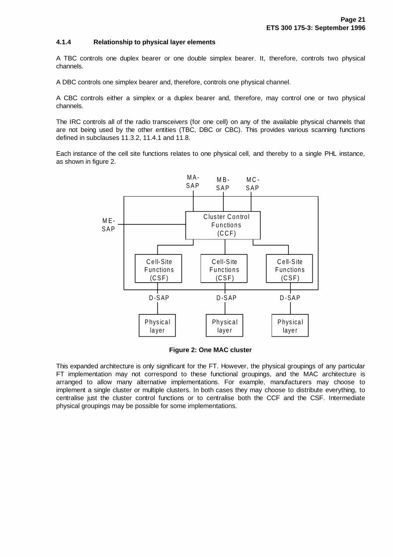
Each instance of the cell site functions relates to one physical cell, and thereby to a single PHL instance,as shown in figure 2.
C lus ter C o n tro lF u n ctio n s
(C C F )
C e ll-SiteF un ction s
(C S F )
C ell-S iteF u nc tio n s
(C S F )
C e ll-S iteF un ction s
(C S F )
P hys ic a lla yer
Ph y sic a llaye r
P hys ica llaye r
D -S AP D -S AP D -SA P
M E -S A P
M A -S A P
M B -S A P
M C -S A P
Figure 2: One MAC cluster
This expanded architecture is only significant for the FT. However, the physical groupings of any particularFT implementation may not correspond to these functional groupings, and the MAC architecture isarranged to allow many alternative implementations. For example, manufacturers may choose toimplement a single cluster or multiple clusters. In both cases they may choose to distribute everything, tocentralise just the cluster control functions or to centralise both the CCF and the CSF. Intermediatephysical groupings may be possible for some implementations.

Page 22ETS 300 175-3: September 1996
4.2 Frame and multiframe structures
4.2.1 General
There are two hierarchical levels of time division multiplexing:
- frame: a time division multiplex of slots;
- multiframe: a time division multiplex of frames.
Timing is defined by the FP transmissions, and the PP is required to slave all of its transmissions to thesetimings.
Detailed frame timing is defined by the PHL, but slot numbering is defined by the MAC layer.
Multiframe timing is wholly defined by the MAC layer.
4.2.2 Frame structure
A regular Time Division Multiple Access (TDMA) structure is created by the PHL (refer toETS 300 175-2 [2]). This frame defines 24 full-slot positions. Alternatively, each full-slot may be furtherdivided into two half-slots, or two consecutive full slots may be used together as a double slot (see figures3, 4, and 5).
The MAC layer controls the transmission and/or reception of data for every double, full or half slot, byissuing primitives to the PHL. Each primitive specifies the operation for one slot position. Continuousoperation on a given physical channel requires a regular series of primitives.
fu lls lo t
0
fu lls lo t
1
fu lls lo t
2
fu l ls lo t11
fu lls lo t12
fu lls lo t13
fu l ls lo t23
fu lls lo t23
fu lls lo t
0
norm a llyF P tran sm it(P P rec eiv e )
no rm a llyP P tra n sm it(FP receiv e )
ea rlie st la tes t
Figure 3
fu l l- s lo t
h a lf -s lo tL= 1
hal f- s lo tL = 0
e ar lie st la te sto ne slo t
Figure 4
fu ll- s lo t 2 n
ea rl ies t la tes ttw o s lo ts
fu l l-s lo t 2n + 1
d ou b le s lo t K = 2 n
Figure 5

Page 23ETS 300 175-3: September 1996
Full-slots are numbered from K = 0 to 23, and half-slots are numbered L = 0 or 1, where half-slot 0 occursearlier than half-slot 1. Double slots are numbered from K = 0 to 22, where K is an even number, i.e. KMOD 2 = 0.
Normally slots K = 0 to 11 are used in the FP to PP direction, and slots K = 12 to 23 in the PP to FPdirection.
Slot numbers (frame timing) are not included in every slot transmission. Slot numbers are only defined in aspecial (Q-channel) message that is transmitted at a low rate by all FPs. This message defines the actualslot number for that transmission (see subclause 7.2.3).
This also applies to a PP acting as the RFP in PP-to-PP direct communication mode.
4.2.3 Multiframe structure
The MAC layer superimposes a multiframe structure on the TDMA frame structure. This is a Time DivisionMultiplex (TDM) of 16 frames. The multiframe starts and ends on a frame boundary, as shown in figure 6.
f ra m e0
fram e1
f ra m e2
fram e1 3
f ra m e1 4
fram e15
f ra m e1 5
ea rl ies t lates to ne m ul ti- fr am e
Figure 6
The multiframe numbering is defined in the same way for the FP and the PP. A multiframe normally startswith FP transmissions (first half of frame 0) and ends with PP transmissions (last half of frame 15).
Frame numbers (multi-frame timing) are never included in a transmission. Frame numbers shall beinterpolated from the multiframe marker that is included in all FP transmissions. This marker appears onceper multiframe (in frame 8) (see subclauses 6.2.2.1 and 7.2.3).
When encryption is provided, an explicit multiframe number is also defined using a similar technique to slotnumbering:
- a special (Q-channel) message is transmitted at a low rate by the FP. This message defines theactual multiframe number for that transmission (see subclause 7.2.3).

Page 24ETS 300 175-3: September 1996
4.3 State definitions
4.3.1 PP states
Id leLocked
A c tiveU n locked
IdleU n locked
A ctiv eLo cke d
"s w itc h of f "
"sw itch on"n o su ita b leR FP fo un d
sui tab leR F P
first bearerestab lished
last bearerre leased
Figure 7: PP state diagram
A PP can exist in one of four major states at the MAC layer:
1) Inactive: where the RFP is not receiving or transmitting. Note that the inactive state is not shown inthe state diagram of figure 8.
2) Active_Locked: where the PP is synchronised to at least one RFP transmission and has one ormore connections in progress.
3) Idle_Locked: where the PP is synchronised to at least one RFP transmission. It is able to make orreceive connections, but has no connections in progress.
4) Active_Unlocked: where the PP is not synchronised to any RFP transmissions, and is unable tomake or receive connections. The PP makes occasional attempts to detect a suitable RFP andenter the Idle_Locked state.
5) Idle_Unlocked: the PP is not synchronised to any RFP and does not attempt to detect RFPs.
Several different modes of operation exist in the Idle_Locked state:
a) scanning mode: where the PP's receiver scan sequence is synchronised with that of the RFP;
b) high duty cycle Idle_Locked mode: where the PP receives 6 times per multiframe;
c) normal Idle_Locked mode: where the PP typically receives once per multiframe;
d) low duty cycle Idle_Locked mode: where the PP typically receives less than once per multiframe.

Page 25ETS 300 175-3: September 1996
4.3.2 RFP states
las t tra ff icbeare rre leased
first tra ff ic beare r es tab lished and dum m y o r C /L b eare r re leased
last tra ffic beare r re leased and dum m y o r C /L beare r e stab lished first tra ff ic
beare res tab lished
re lease o f las t dum m y o r C /L b earer
A c tive Id le
Ac tiveT raffic
es tab lish du m m y o r C /L beare r
ActiveTraffic andIdle
Figure 8: RFP state diagram
An RFP can exist in one of four major states at the MAC layer:
1) Inactive: where the RFP is not receiving or transmitting;
2) Active_Idle or C/L: where the RFP has either at least one dummy bearer or at least oneconnectionless downlink bearer, and a receiver that is scanning the physical channels in a knownsequence;
3) Active_Traffic: where the RFP has at least one traffic bearer, but does not have a dummy or aconnectionless downlink bearer;
4) Active_Traffic_and_Dummy or C/L: where the RFP has at least one traffic bearer and is alsomaintaining one dummy or connectionless downlink bearer.

Page 26ETS 300 175-3: September 1996
5 Overview of MAC layer services
5.1 General
The MAC layer offers three groups of services to the upper layers and to the management entity. Theseservice groupings are related to the functional groupings in the cluster control functions:
- broadcast message control;
- connectionless message control;
- multi-bearer control.
Each individual service is accessed via an independent service endpoint, and these endpoints are groupedinto three Service Access Points (SAPs). Each service endpoint contains one or more logical channels. Afourth group of logical channels is provided for internal (peer-to-peer) MAC control information. The logicalchannels are described in subclause 5.3 and the SAPs are described in subclause 5.4.
5.1.1 Broadcast Message Control (BMC)
The BMC provides a set of continuous point-to-multipoint connectionless services. These are used to carryinternal logical channels, and are also offered to the higher layers via the MA-SAP. These services operatein the direction FT to PT, and are available to all PTs within range.
The BMC services operate on all bearers, with each bearer carrying similar (equivalent) messages. TheBMC services may appear alone, but they also appear combined with both of the other services, therebyproducing bearers that contain data from two services (i.e. a single physical packet contains fields fromboth services).
5.1.2 Connectionless Message Control (CMC)
The CMC provides connectionless point-to-point or point-to-multipoint services to the higher layers via theMB-SAP. These services may operate in both directions between one specific FT and one or more PTs.
5.1.3 Multi-Bearer Control
Each instance of MBC provides one of a set of connection oriented point-to-point services to the higherlayers via the MC-SAP. These services may operate in both directions or in one direction between onespecific FT and one specific PT. Each service instance provides a connection (a connection orientedservice) between one FT and one PT.
An MBC service may use more than one bearer to provide a single service. In this event, these multiplebearers may be used to carry duplicated data (to provide redundancy) and/or distributed data (to provideincreased bandwidth).
5.2 Service descriptions
5.2.1 Common functions
All services shall only operate between one FT and one or more PTs.
All the services provide the following functions:
a) the means to monitor signal quality;
b) the means to provide error control for some data.

Page 27ETS 300 175-3: September 1996
5.2.2 BMC service
The BMC service provides two types of broadcast information in the direction FT to PT:
- permanent broadcasts containing the two MAC control channels, Q and N (see subclauses 5.3.4.1and 5.3.4.2);
- transient broadcasts containing the MAC paging channel, BS (see subclause 5.3.3.1).
The BMC service provides the following additional functions to the PT:
a) the means to acquire and maintain frame and multiframe synchronism between transmitters andreceivers;
b) the means to obtain primary and secondary access right identities;
c) the means to supply paging messages to the higher layers.
5.2.3 CMC service
The CMC service provides two alternative services:
- higher layer connectionless C-plane information, using the CLS and CLF channels (seesubclause 5.3.2.1);
- higher layer connectionless U-plane information, using the SIN and the SIP channels (seesubclause 5.3.2.2).
A single CCF may contain one single CMC instance. This CMC instance cannot be combined with an MBCconnection service.
The CMC service provides the following additional function:
- the means to multiplex more than one logical channel onto each MAC bearer of the broadcast, withdefined priorities.
5.2.4 MBC services
Each MBC instance can provide two separate connection oriented services to the higher layer:
- higher layer C-plane information, contained in the C-channels (see subclause 5.3.1.1);
- higher layer U-plane information contained in the I and GF channels (see subclauses 5.3.1.2 and5.3.1.3).
These two services are independent, and may be provided in combination or separately as part of a givenMBC service. The overall service may be bidirectional, or unidirectional (in either direction). The chosenservice type(s), and the service directions are defined during MBC connection establishment.
Each MBC service provides the following additional functions:
a) the means to set up, maintain and clear down a variety of different connections using one or morebearers (duplex bearers and/or double simplex bearers);
b) the ability to preserve connection quality by performing individual "bearer handover" of any duplex ordouble simplex bearers;
c) the means to multiplex more than one logical channel onto each MAC bearer of the connection, withdefined priorities;

Page 28ETS 300 175-3: September 1996
d) the means to encrypt optionally all higher layer data.
5.3 Logical channels
The following logical channels are defined:
a) MBC connection endpoints (MC-SAP logical channels):
C-channels: CS and CF;I channels: IN and IP;GF channel;
b) CMC service endpoint (MB-SAP logical channels):
CL channels:CLS and CLF;SIN channel and SIP channel;
c) BMC broadcast endpoint (MA-SAP logical channel):
BS channel;
d) Internal MAC control channels:
Q-channel;N-channel;M-channel;P-channel.
5.3.1 MBC connection endpoints (MC-SAP logical channels)
5.3.1.1 The higher layer C-plane channels, C
Higher layer information from the DLC C-plane uses the C-channels, these are two independent channels,the CS channel and the CF channel.
The CS channel is a slow duplex channel for higher layer information. It offers a low capacity which can beused by the higher layers with virtually no restriction. The transmission of CS channel data reduces thethroughput of the logical N-channel.
The CF channel is a fast duplex channel for higher layer information with a higher capacity than the CSchannel. Transmissions of CF channel data may reduce the throughput of, or interrupt, the logical I channel.
All C-channel information is protected by MAC layer error control which uses error correction based on anAutomatic Repeat reQuest (ARQ).
5.3.1.2 The higher layer U-Plane channels, I
Higher layer information from the DLC U-plane uses the I channels. These are the IN channel and the IPchannel, and they have different MAC layer protection schemes. The higher layers choose one of the twochannels, the IN and IP channels shall not be used in parallel for the same connection.
The IN information is protected by limited MAC layer error detection (X-field) and may include a minimumdelay mode for coded speech transmission. Depending on the physical packet size the MAC layerprocesses IN channel data in fields of different length.
The IP information is protected by MAC layer procedures, either error correction based on a modulo 2retransmission scheme or just error detection based on 16 bit CRCs. The DLC layer requests a servicetype, maximum allowed transmission time, and target and minimum acceptable numbers of uplink anddownlink bearers which the MAC layer tries to provide.

Page 29ETS 300 175-3: September 1996
5.3.1.3 The higher layer U-Plane control channel, G F
Higher layer U-plane control from the DLC uses the GF channel.
The GF channel is a fast simplex channel that is used to provide control of U-plane entities. For example, itis used to carry acknowledgements for asymmetric connections.
All GF channel information is protected by a MAC layer error control which allows error detection.
5.3.2 CMC endpoints (MB-SAP logical channels)
5.3.2.1 The connectionless C-Plane channels, C L
Higher layer connectionless information from the DLC C-plane uses the CL channels, these are twoindependent channels, the CLS channel and the CLF channel.
The CLS channel is a slow simplex channel for higher layer information. It offers a low capacity which canbe used by the higher layers with virtually no restriction. The transmission of CLS channel data reduces thethroughput of the logical N-channel.
The CLF channel is a fast simplex channel for higher layer information with a higher capacity than the CLSchannel.
All CL channel information is protected by MAC layer error control which allows error detection.
5.3.2.2 The connectionless U-Plane channels, SI N and SIP
Higher layer connectionless information from the DLC U-plane uses the SIN and SIP channels.
The SIN information is protected by limited MAC layer error detection (X-field) and can be used for codedspeech transmission. Depending on the physical packet size the MAC layer processes SIN channel data infields of different length.
The SIP information is protected by MAC layer error detection procedures based on 16 bit CRCs.
5.3.3 BMC endpoint (MA-SAP logical channel)
5.3.3.1 The slow broadcast channel, B S
The slow broadcast channel, BS, is a simplex data channel in the direction FT to PTs. It is used tobroadcast transient information from RFPs to all PTs that are listening. BS channel data is transmitted byRFPs on traffic, connectionless, and dummy bearers. BS channel information is available to Idle_Lockedand Active_Locked PTs.
The transmission of BS channel data reduces the throughput of the logical N-channel.
All BS channel information is protected by MAC layer error control which allows error detection.
NOTE: A typical use for the BS channel is to broadcast call set up requests; however, otheruses are allowed.

Page 30ETS 300 175-3: September 1996
5.3.4 Internal MAC control channels
5.3.4.1 The system information channel, Q
The system information channel, Q, is a simplex data channel used to supply PTs with information aboutthe DECT fixed system. Most Q-channel data is transmitted as repeated broadcasts on traffic,connectionless and dummy bearers. Q-channel data may also be transmitted on request.
Some Q-channel information is needed by a PT to change from the Active_Unlocked state to theIdle_Locked state.
All Q-channel information is protected by MAC layer error control which allows error detection.
5.3.4.2 Identities channel, N
The identities channel, N, is used for repeated transmissions of a system identity. N-channel data istransmitted by RFPs on traffic, connectionless and dummy bearers, and by PTs on traffic bearers.
The identities channel N has two purposes:
- for Active_Unlocked PPs the N-channel has a similar function as the Q-channel. Here the N-channelcan be considered as a simplex channel in the RFP to PP direction. The broadcast identity helpsactive unlocked PPs to find a system which offers the desired service and to which they haveaccess rights;
- for Active_Locked PPs the N-channel is received on all FP to PP bearers and echoed on all PP toFP bearers to provide a MAC layer handshake.
All N-channel information is protected by MAC layer error control which allows error detection.
5.3.4.3 The MAC control channel, M
The M channel is used to carry MAC layer information. This information appears in three differentpositions:
- MAC control in all header fields (see subclause 6.2.1.2);
- MAC control in a tail field (see subclause 6.2.2.1);
- MAC control in any B-subfield (see subclause 6.2.2.3).
MAC control forms an integral part of all three services. When used on a duplex bearer (as part of theMBC service) it conveys point-to-point MAC control. On all services it is also used to broadcast MAC layerstatus information.
All M channel information is protected by MAC layer error control which allows error detection.
5.3.4.4 MAC paging channel, P
The P-channel is used to carry paging messages. Each of these messages may contain one segment ofdata from the BS logical channel.
The P-channel appears as a part of all bearers transmitting in the direction FT to PT. The P-channel isnormally the only channel that is received by an PT in the Idle_Locked state.
All P-channel information is protected by a MAC layer error control which allows error detection.
Page 31ETS 300 175-3: September 1996
5.4 SAP definitions
The MAC layer communicates with the DLC layer through 3 SAPs. These SAPs are the MA SAP, the MBSAP and the MC SAP.
The MAC layer communicates with the management entity through the ME SAP.
The MAC layer communicates with each PHL instance through an independent D SAP. The D SAP isdefined in ETS 300 175-2 [2].
5.4.1 MA SAP
This is a SAP between the MAC and DLC layers. The SAP contains a single broadcast endpoint,containing one logical channel, the BS channel. The primitives passed through the MA SAP are used to:
- carry BS channel data; and
- control the data flow of the BS channel data.
The BS channel provides a connectionless simplex (broadcast) service in the direction FT to PT.
The permitted SDU lengths in primitives carrying BS channel data are 0, 20, 36, 72, 108, 144, 180 or 216bits.
5.4.2 MB SAP
This is a SAP between the MAC and the DLC layer. The MB SAP contains one service endpoint with fourlogical channels, the CLF, CLS, SIN and SIP channels.
The CLS and CLF channels provide connectionless services in both directions, FT to PT and PT to FT. Indirection FT to PTs the connectionless service is continuous, in direction PT to FT the service isdiscontinuous.
The permitted SDU length in primitives containing CLS channel data is 40 bits (= 1 CLS segment).
The permitted SDU length in primitives containing CLF channel data is an integer multiple of the CLF datasegment length, which is 64 bits.
The SIN channel offers one unprotected simplex service to the higher layers (FT to PT only).
The SIP channel offers one protected simplex service to the higher layers (FT to PT only).
For the SIN service the SDU length corresponds to the size of the SIN data fields in the U-type multiplexes(see subclause 6.2.2.2).
For the SIP service, the SDU length is an integer multiple of 32 octets or 256 bits (see subclause 6.2.2.2).
5.4.3 MC SAP
This is a SAP between the MAC and DLC layers. The SAP may contain multiple connection endpoints, andfive logical channels are associated with each endpoint; CS, CF, GF, IN, and Ip channels. Primitivestransferred through this SAP are used to:
- control the MAC processes to establish, maintain and release connections;
- carry CS, CF, GF, IN and IP channel data; and
- control the data flow of the CS, CF, GF, IN and IP channel data.
The CS and the CF channel offer two independent connection-oriented duplex services.
Page 32ETS 300 175-3: September 1996
For one connection the maximum throughput of CS channel data is 2 kbps. The SDU length of primitivescarrying CS channel data is equal to the CS data segment length of 40 bits.
The maximum throughput of CF channel data is 6,4 kbit/s for half slot connections, 25,6 kbit/s for full slotconnections, and 64 kbit/s for double slot connections. For CF channel data the SDU length is an integermultiple of the CF data segment length, which is 64 bits.
The IP and IN channels offer two independent connection orientated duplex services to the higher layers.One service uses either the logical IN or the logical IP channel.
For all data services the SDU length is an integer multiple of the I channel data segment length. Thesegment length need not be the same for every service and corresponds to the size of the IN and IP datafields in the U-type multiplexes (see subclause 6.2.2.2).
The GF channel offers a connection oriented simplex service. The GF SDU length is 56 bits.
5.4.4 ME SAP
This is a SAP between the MAC layer and the management entity. There is no formal definition for thisinterface, i.e. no endpoints and no logical channels are defined.
The following information is transferred:
- control of certain MAC processes (e.g. encryption);
- transfer of certain broadcast data (e.g. FP identities).
5.4.5 Order of transmission
Certain primitives exchanged between the MAC layer and the DLC layer may have a SDU containingpeer-to-peer messages. The SDU data is arranged as a list of octets or part octets, starting with octet 1.The bits within one octet are numbered from 1 to 8 where the most significant bit has number 8. The MAClayer transmits these octets in ascending order, starting with octet 1. Valid bits within one octet aretransmitted in descending order.
5.5 Bearers
MAC bearers are the elements that are created by each cell site function. Each bearer corresponds to asingle service instance to one PHL. Duplex and double-simplex bearers may be combined by the MBC toprovide complete MAC connections to provide a co-ordinated connection oriented service (seesubclause 5.6).
Page 33ETS 300 175-3: September 1996
5.5.1 Bearer types
Four types of bearer are defined:
1) simplex bearer : a simplex bearer is created by allocating one physical channel for transmissions inone direction. Two types of simplex bearers exist, short and long simplex bearers. The short simplexbearers only contain the A-field whereas long simplex bearers contain the A-field and the B-field(refer to subclause 6.2.1). One simplex bearer is created by one dummy bearer controller or by oneconnectionless bearer controller. A DBC shall always control a short simplex bearer;
2) duplex bearer : a duplex bearer is created by a pair of simplex bearers, operating in oppositedirections on two physical channels. These pairs of channels shall always use the same RF carrierand shall always use evenly spaced time slots (i.e. the starting points of the time slots areseparated by 0,5 frame). One duplex bearer is created by one traffic bearer controller or oneconnectionless bearer controller. A duplex bearer controlled by a TBC always contains the A-fieldand the B-field in both directions (refer to subclause 6.2.1);
3) double simplex : a double simplex bearer is created by a pair of long simplex bearers operating inthe same direction on two physical channels. These pairs of channels shall always use the same RFcarrier and shall always use evenly spaced time slots (i.e. the starting points of the time slots areseparated by 0,5 frame). Double simplex bearers shall only exist as part of a multi-bearerconnection. One double simplex bearer is created by one traffic bearer controller;
4) double duplex bearer: a double duplex bearer is composed by a pair of duplex bearers referring tothe same MAC connection. Each duplex bearer is created by one TBC and the pair is controlled bythe same MBC. The duplex bearers share their simplex bearers for the information flow.
Transmission on a bearer uses the PL_TX primitive, where the SDU in each PL_TX-req primitive containsthe data for one slot (for one transmission).
Reception on a bearer uses the PL_RX primitive, where the SDU in each PL_RX-cfm primitive contains thedata for one slot (for one reception).
5.5.2 Bearer operation
A bearer can exist in one of three operational states:
1) dummy bearer: where there are normally continuous transmissions (i.e. one transmission in everyframe, refer to subclause 5.7). These transmissions never contain data related to the MC or the MBSAP. A dummy bearer only supports BMC services. A dummy bearer is a short simplex bearer;
2) traffic bearer: where there are continuous point-to-point transmissions that usually contain MC SAPdata but never contain data related to the MB SAP. A traffic bearer supports both, BMC and MBCservices. A traffic bearer is a duplex bearer or a double simplex bearer;
3) connectionless bearer: where there are transmissions that may contain MB SAP data but nevercontain data related to the MC SAP. A connectionless bearer supports both BMC and CMCservices. In the direction FT to PTs a connectionless bearer is either duplex if the RFP also supportsthe connectionless uplink service, or simplex if it does not support the connectionless uplink service.For a PT, a connectionless bearer is either a simplex or a duplex bearer.
"Logical bearer" defines the effective service available from one traffic bearer. During bearer handover twoidentical duplex or double simplex bearers may exist to provide the service of one logical bearer. At allother times each logical bearer corresponds to one duplex or double simplex bearer.

Page 34ETS 300 175-3: September 1996
5.6 Connection oriented services
Each MBC instance creates one MAC connection, and provides an independent service to the higher(DLC) layer. A MAC connection is wholly contained within one cluster, using the services of one or moreTBCs within that cluster.
Each MAC connection may use the services of one or more bearers. A single-bearer connection shall usea single duplex bearer. A multi-bearer connection shall use one duplex bearer plus one or more additionalduplex and/or double simplex bearers.
5.6.1 Connection types
The MAC provides C-channel and I-channel services to the DLC layer by setting up and maintaining MACconnections.
All RFPs of a cluster shall provide the same capabilities to transmit higher layer control (in particular, theCF and GF channel capabilities shall be the same).
Three type of connections are defined:
- basic connections;
- advanced connections;
- physical connections.
5.6.1.1 Basic connections
Basic connections have no common connection number (common is defined to mean the same connectionnumber is known at both PT and FT). Therefore, only one basic connection may exist between a PT(identified by its PMID) and one particular FT (identified by the ARI).
Exception: During connection handover two basic connections may exist, serving the sameDLC link.
Basic connections only provide one full slot duplex bearer for the IN_minimum_delay service. Becausebasic connections are always single bearer connections no Logical Bearer Number (LBN) is assigned tothe bearer for these connections.
Basic connections shall not support CF, GF and IP channels and shall not send MAC extended control in theB-field.
5.6.1.2 Advanced connections
Advanced connections have a common connection number, called Exchanged Connection Number (ECN)which is assigned by the LLME. Therefore, more than one advanced connection may exist between a PTand one FT. Advanced connections may provide any service listed in subclauses 5.6.2.1 and 5.6.2.2.
Bearers of advanced connections are labelled by the MAC with LBNs (common parameters). The LBNenables the MAC to distinguish between different bearers in the same connection.
Advanced connections created with the A-field MAC messages (see subclause 10.2.4) may support the CFchannel. If the wanted service needs a GF channel the connection shall support the CF channel.
Advanced connections created with the B-field MAC messages shall support the CF channel.

Page 35ETS 300 175-3: September 1996
5.6.1.3 Connection identifiers
Locally each connection (each instance of an MBC) is always identified by a MAC Connection EndpointIdentification (MCEI). This MCEI allows the DLC to select one particular connection. In the PT the MCEI isassigned by the LLME and is unique within that PT. In the FT the MCEI is assigned by the LLME and isunique within that FT identified by its ARI. In general the MCEIs will be different in the PT and the FT forany given connection.
For advanced connections, a further common identifier, the ECN, is transmitted between PT and FT. Thefull identifier consists of ARI + PMID + ECN. PMID and ARI identify the PT and the FT. The ECN allowsdifferent advanced connections between the same PT and FT to be distinguished. The DLC and MAC atboth ends know this common identifier.
5.6.1.4 Physical connections
Physical connections only provide one duplex bearer without referring to a particular service.
Physical connections do not require the opening of a DLC link and can be identified at the MAC layer bythe PMID.
A physical connection can be linked to a duplex bearer of a basic or an advanced connection by a mappingprocedure (see subclause 10.5.1.6); after the mapping, it shall acquire the same properties of the linkedchannel and shall be referred to the same connection. The two linked bearers constitute a double duplexbearer.
5.6.2 Symmetric and asymmetric connections
The different connection oriented service types are divided into two categories, symmetric and asymmetricconnections:
- symmetric connections will always have the same number of simplex bearers in both transmissiondirections. Moreover the service characteristics (see subclause 5.6.2.1) and their bandwidths arethe same for both directions;
- asymmetric connections have a different number of logical simplex bearers for both transmissiondirections. Typically, there are only one or two bearers in the "reverse" direction. Although theservices in both directions have the same characteristics the bandwidth of the services will differ.
- Multibearer connections exist only in full slot and double slot transmission mode. This means thatasymmetric connections are not permitted in half slot transmission mode. All bearers of amultibearer connection shall be from the same slot type, i.e. either full slot or double slot.
- It is also assumed that asymmetric connections are fully asymmetric, that is, I channel data onlyflows in one direction.
In all connections, the DLC gives the MAC a "target number of bearers" and a "minimum acceptablenumber of bearers" to establish. When the connection has been established (or set up has failed), theMAC tells the DLC the "actual number of bearers" that have been established. In many cases the "targetnumber of bearers" equals the "minimum acceptable number of bearers".
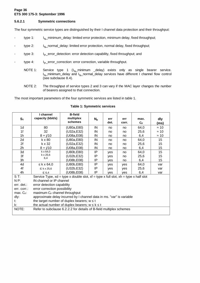
Page 36ETS 300 175-3: September 1996
5.6.2.1 Symmetric connections
The four symmetric service types are distinguished by their I channel data protection and their throughput:
- type 1: IN_minimum_delay: limited error protection, minimum delay, fixed throughput;
- type 2: IN_normal_delay: limited error protection, normal delay, fixed throughput;
- type 3: IP_error_detection: error detection capability, fixed throughput; and
- type 4: IP_error_correction: error correction, variable throughput.
NOTE 1: Service type 1 (IN_minimum _delay) exists only as single bearer service.IN_minimum_delay and IN_normal_delay services have different I channel flow control(see subclause 8.4).
NOTE 2: The throughput of service types 2 and 3 can vary if the MAC layer changes the numberof bearers assigned to that connection.
The most important parameters of the four symmetric services are listed in table 1.
Table 1: Symmetric services
ST
I channelcapacity (kbit/s)
B-fieldmultiplexschemes
Np errdet.
errcorr.
max.CF
dly(ms)
1d1f1h
8032
8 + j/10
(U80a,E80)(U32a,E32)(U08a,E08)
INININ
nonono
nonono
64,025,66,4
≈ 10≈ 10≈ 10
2d2f2h
k x 80k x 32
8 + j/10
(U80a,E80)(U32a,E32)(U08a,E08)
INININ
nonono
nonono
64,025,66,4
151515
3d3f3h
k x 64,0k x 25,6
6,4
(U80b,E80)(U32b,E32)(U08b,E08)
IPIPIP
yesyesyes
nonono
64,025,66,4
151515
4d4f4h
≤ k x 64,0≤ k x 25,6
≤ 6,4
(U80b,E80)(U32b,E32)(U08b,E08)
IPIPIP
yesyesyes
yesyesyes
64,025,66,4
varvarvar
S T: Service Type, xd = type x double slot, xf = type x full slot, xh = type x half slotN P: IN channel or IP channelerr. det.: error detection capabilityerr. corr.: error correction possibilitymax. CF: maximum CF channel throughputdly: approximate delay incurred by I channel data in ms. "var" is variablet: the target number of duplex bearers; w ≤ tk: the actual number of duplex bearers; w ≤ k ≤ tNOTE: Refer to subclause 6.2.2.2 for details of B-field multiplex schemes
Page 37ETS 300 175-3: September 1996
5.6.2.2 Asymmetric connections
General principles:
a) simplex bearers are always allocated in pairs;
b) pairs of simplex bearers are one half TDMA frame apart;
c) there exists (k + m + n) simplex bearers where k ≥·m + n ≥ 1. k bearers are in the main, "forward"data direction and m + n bearers are in the opposite, "reverse" direction;
d) all the k bearers in the forward direction have the same format;
e) the n bearers in the reverse direction are called "special" bearers. Depending on the slot type thesebearers have the E32 or the E80 format. They may be used to report reception quality on thedouble simplex bearers in the forward data direction and carry GF channel data. These specialbearers shall not carry I channel data;
f) the m data bearers in the reverse direction have the same format as the k bearers in the forwarddirection.
NOTE: n > 0.
The three asymmetric service types are distinguished by their I channel data protection and theirthroughput:
- type 5: IN_normal_delay : limited error protection, normal delay, fixed throughput;
- type 6: IP_error_detection : error detection capability, fixed throughput;
- type 7: IP_error_correction : error correction, variable throughput.
Table 2 shows the most important parameters for asymmetric connections. The first line in eachdescription defines the forward data direction. The second and third line describe the reverse direction.The same abbreviations are used as in table 1 except:
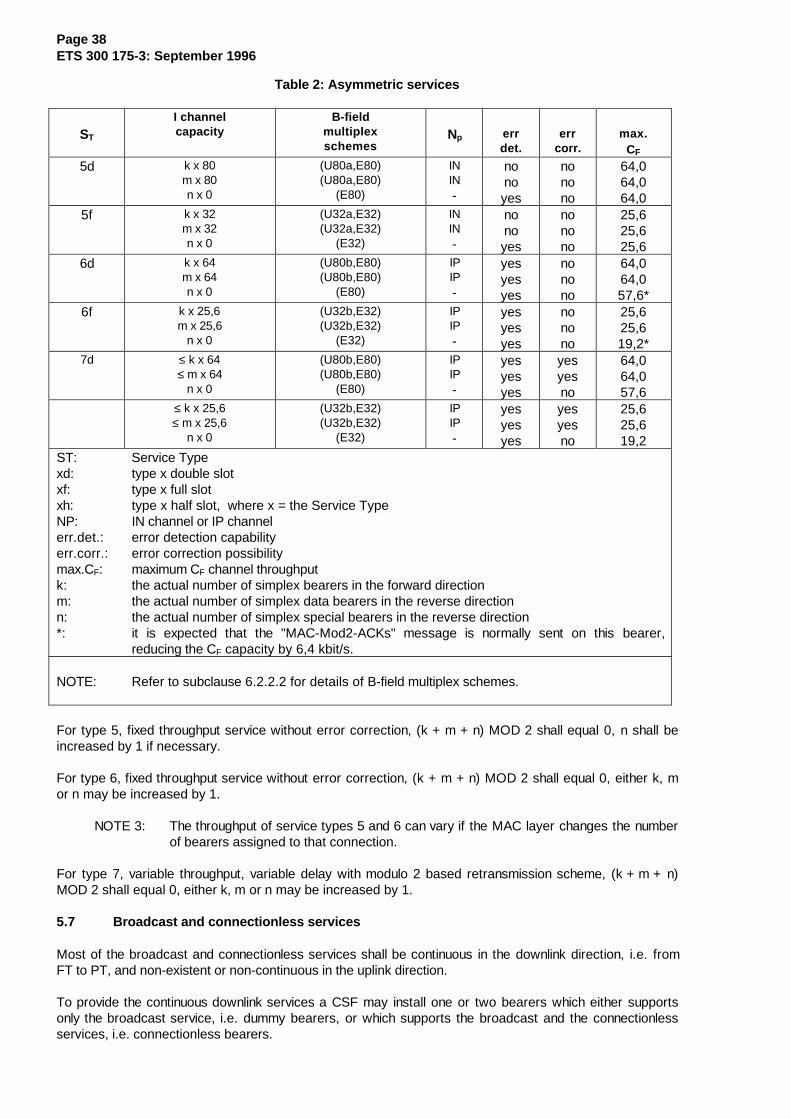
Page 38ETS 300 175-3: September 1996
Table 2: Asymmetric services
ST
I channelcapacity
B-fieldmultiplexschemes
Np errdet.
errcorr.
max.CF
5d k x 80m x 80n x 0
(U80a,E80)(U80a,E80)
(E80)
ININ-
nonoyes
nonono
64,064,064,0
5f k x 32m x 32n x 0
(U32a,E32)(U32a,E32)
(E32)
ININ-
nonoyes
nonono
25,625,625,6
6d k x 64m x 64n x 0
(U80b,E80)(U80b,E80)
(E80)
IPIP-
yesyesyes
nonono
64,064,057,6*
6f k x 25,6m x 25,6
n x 0
(U32b,E32)(U32b,E32)
(E32)
IPIP-
yesyesyes
nonono
25,625,619,2*
7d ≤ k x 64≤ m x 64
n x 0
(U80b,E80)(U80b,E80)
(E80)
IPIP-
yesyesyes
yesyesno
64,064,057,6
≤ k x 25,6≤ m x 25,6
n x 0
(U32b,E32)(U32b,E32)
(E32)
IPIP-
yesyesyes
yesyesno
25,625,619,2
ST: Service Typexd: type x double slotxf: type x full slotxh: type x half slot, where x = the Service TypeNP: IN channel or IP channelerr.det.: error detection capabilityerr.corr.: error correction possibilitymax.CF: maximum CF channel throughputk: the actual number of simplex bearers in the forward directionm: the actual number of simplex data bearers in the reverse directionn: the actual number of simplex special bearers in the reverse direction*: it is expected that the "MAC-Mod2-ACKs" message is normally sent on this bearer,
reducing the CF capacity by 6,4 kbit/s.
NOTE: Refer to subclause 6.2.2.2 for details of B-field multiplex schemes.
For type 5, fixed throughput service without error correction, (k + m + n) MOD 2 shall equal 0, n shall beincreased by 1 if necessary.
For type 6, fixed throughput service without error correction, (k + m + n) MOD 2 shall equal 0, either k, mor n may be increased by 1.
NOTE 3: The throughput of service types 5 and 6 can vary if the MAC layer changes the numberof bearers assigned to that connection.
For type 7, variable throughput, variable delay with modulo 2 based retransmission scheme, (k + m + n)MOD 2 shall equal 0, either k, m or n may be increased by 1.
5.7 Broadcast and connectionless services
Most of the broadcast and connectionless services shall be continuous in the downlink direction, i.e. fromFT to PT, and non-existent or non-continuous in the uplink direction.
To provide the continuous downlink services a CSF may install one or two bearers which either supportsonly the broadcast service, i.e. dummy bearers, or which supports the broadcast and the connectionlessservices, i.e. connectionless bearers.

Page 39ETS 300 175-3: September 1996
If two bearers are installed both bearers shall support the same services. The maximum of two bearers forone CSF is only allowed when:
a) no traffic bearer with downlink transmissions exists at the CSF; and
b) the FP has multiple RFPs with different FMIDs (refer to subclause 11.7), and provides inter-cellhandover capability.
If a CSF uses two bearers for this service, the CSF shall stop transmissions on one of these bearers, (i.e.release the bearer), within 4 multiframes after establishment of the first traffic bearer with downlinktransmissions.
The only exception to the above rule applies when the CSF decides to change the physical channel(s) forone of these particular bearers. In this case the CSF may maintain one additional bearer to provide thecontinuous downlink services for a duration of up to 4 multiframes. At most one bearer for this continuousdownlink service may change the physical channel(s) at the time. The number of physical channel changesfor this exception shall not exceed 5 changes per any one minute interval.
If a DBC or CBC is selected for the continuous downlink service this bearer shall normally transmit onceper frame in downlink direction. The only allowed exception applies for quality control purposes of thechosen physical channel, e.g. RSSI measurements. A DBC or CBC may miss at most one downlinktransmission in any one second interval, provided that:
a) CMC services are not affected (CBC only);
b) the BMC paging service (refer to subclause 9.1.3) is not affected.
It is further not allowed to miss transmissions in frames 0,8 and 14 of a multiframe (refer tosubclause 6.2.2.1.1).
NOTE: If no CMC service is provided, the broadcast service may be offered by a traffic bearerof an ongoing connection. The exception of missing one frame's transmission does notapply for the TBC controlling this traffic bearer.
PT attempts to setup a traffic bearer using the same physical channel(s) as used for a connectionlessdownlink service shall be ignored by the CSF. With the system capabilities message the FT tells the PTwhether or not a bearer setup attempt on dummy bearer(s) is allowed. If setup is prohibited a CSF shallignore attempts to setup a bearer using the same physical channel as a dummy bearer.
5.7.1 The broadcast services
Two broadcast services are defined, a continuous and a non-continuous broadcast service.
5.7.1.1 The continuous broadcast service
The continuous broadcast service is a simplex service in the direction FT to PT, and is controlled by theBMC.
This service allows PTs to lock on to an FT and to acquire access rights and service related information(see subclause 5.2.2). The service is available on all bearers with continuous transmissions in direction FTto PT. This can be a dummy bearer, a traffic bearer or a connectionless bearer.
Each RFP of an FP shall maintain at least one bearer with continuous broadcast transmissions. If an RFPmaintains neither a traffic bearer nor a connectionless bearer with continuous transmissions the RFP shallinstall at least one dummy bearer to provide the broadcast service. Dummy bearers exist only in thedownlink direction, i.e. FT to PT.
Data of the continuous broadcast service are always transmitted in the A-field (refer to subclause 6.2.1).The functionality of the service is determined by the rules to distribute data from all broadcast channels intothe A-field of consecutive frames within one multiframe (refer to subclause 6.2.2).
Page 40ETS 300 175-3: September 1996
5.7.1.2 The non-continuous broadcast service
The non-continuous broadcast service allows the PTs to obtain extended system information on request.This service is controlled by the BMC and works on a transient duplex bearer. The service needs a limitednumber of transmissions in both directions.
The request and the reply data are transmitted either in the A-field or in the B-field (refer tosubclause 6.2.1). The non-continuous broadcast service uses a unique A-field coding for the firsttransmission in either direction (refer to subclause 7.2.5.6). This is in order to distinguish transmissions ofthis service from transmissions of other connectionless services.
5.7.2 The connectionless services
The connectionless services allow multicast transmission of higher layer C-plane and U-plane data from anFT to PTs, and point-to-point transmission of higher layer C-plane data from a PT to one FT. Theseservices are controlled by the CMC. The FT to PTs connectionless service may be continuous (i.e. onetransmission in every frame). In the direction PT to FT, transmission is limited to a maximum of two slots intwo successive frames.
5.7.2.1 Connectionless downlink services
The connectionless downlink service offers a continuous simplex service to the DLC. Only one CMCdownlink service may exist within each cluster.
Connectionless bearers used for a downlink service are marked by a special header code and may also beannounced by using the BMC service.
A connectionless downlink service shall use CBCs controlling a duplex bearer or, if the CMC does notprovide an uplink service, CBCs controlling a simplex bearer. If two CBCs are installed at a CSF to providethe connectionless downlink service all data of this service shall be duplicated on both CBCs.
NOTE 1: The number of allowed CBCs per CSF for connectionless downlink services isrestricted (refer to subclause 5.7).
NOTE 2: Connectionless downlink and uplink services are independent.
NOTE 3: A connectionless uplink service may choose another bearer than the duplex bearerwhich is used for the downlink service.
Four types of continuous connectionless simplex services exist. They are distinguished by the logicalchannels supported:
a) only CLS channel;
b) CLS and CLF channels;
c) CLS and SIN channels.
d) CLS and SIP channels.
Service a) shall always use a short simplex bearer for the downlink. The services b) c) and d) use a longsimplex bearer.

Page 41ETS 300 175-3: September 1996
5.7.2.2 Connectionless uplink services
This service uses a CBC controlled bearer. Provided that the CBC controls both, the connectionlessdownlink and uplink service, this bearer is a duplex bearer. Otherwise the CBC controls a simplex bearer.The connectionless uplink service consists of one or two transmissions from the PT to the FT.
The following simplex services are offered to the DLC:
a) CLS-channel only, one CLS segment;
b) CLF-channel only; and
c) no SDU (only PMID passed to the FT's DLC).
Services a) and c) may use either a short simplex bearer or a long simplex bearer for the uplink. Service b)always uses a long simplex bearer for the uplink. All services may work together with either a shortsimplex bearer or a long simplex bearer for the downlink.
The PT uses A-field messages to address the RFP and to identify itself.
6 Multiplexing
To allocate DECT D-channel capacity to carry data from all logical channels defined in subclause 5.3,several controllers, multiplex algorithms and mapping schemes are used. Figures 9 to 12 show the fourpossible MAC layer multiplexing structures, corresponding to the four bearer arrangements.
6.1 CCF multiplexing functions
The MBC establishes and maintains a connection and controls the data flow of the I and C-channels. Forthese purposes the MBC uses MAC control.
In the transmission direction the MBC distributes the data received through the MC SAP to all the TBCs inone connection. This includes the routing of C-channel data to one TBC or duplication of this data to morethan one TBC and the careful management of data from all channels to two TBCs during seamless bearerhandover.
In the receiving direction the MBC collects data from all TBCs. For C-channel data the receiving trafficcontroller removes duplicate data and performs resequencing.
For I-channel services the MBC is either responsible for resequencing the data or it applies aretransmission scheme to correct transmission errors (see subclause 10.8).
Each MBC may contain a key stream generator. This element produces a cypher stream to encrypt ordecrypt all I, GF and C-channel data.
The BMC manages and distributes N, Q and BS-channel data.
Page 42ETS 300 175-3: September 1996
6.2 CSF multiplexing functions
Every TBC or CBC or DBC multiplexes data received from BMC, from CMC and from MBC ontoD-fields for delivery to the physical layer. The following functions are defined:
MAC control: MAC control is needed to setup, maintain and release bearers, and to enable/disableencryption.
Bit MAPpings (MAP): MAPs are spatial multiplexers, that combine two or more fields into a single (larger)field. Three MAPs are defined: A-MAP, B-MAP and D-MAP.
Time MUltipleXers (MUX): MUXs are used to switch between alternative fields on a frame-by-framebasis. They operate synchronously to the applied frame and multiframe timing. Three MUXs are defined:C-MUX, T-MUX and E/U MUX.
Scrambler: scrambling is used to modify specific data fields every frame according to a standard(predefined) pattern (refer to subclause 6.2.4).
Encryption: encryption is used to modify specific data fields according to a secret pattern denoted KSG infigure 9 (refer to subclause 6.2.3). The use of encryption is optional.
Error control (CRC): the error control modules generate extra error control bits (redundancy bits)according to standard cyclic generation algorithms (refer to subclause 6.2.5).
Broadcast control: this is used to merge MAC information with higher layer information as part of theBMC service.
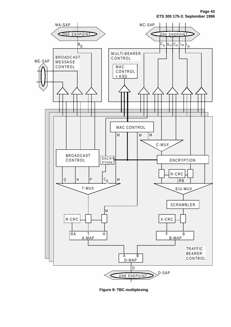
Page 43ETS 300 175-3: September 1996
R - C R C
T-MUX
A-MAP
X - C R C
B-MAP
D-MAP
R - C R C
E/U-MUX
S C R A M B L E R
G
MPNQ CS
MA-SAP MC-SAP
ME-SAP
A B
MM M
M
O N E E N D P O I N TO N E E N D P O I N T
BS
HTRA X B
D-SAPD
O N E E N D P O I N T
ENCRYPTION
C-MUX
R B
MAC CONTROL
INPC FFSC
M U LTI-B EA R E RC O N TR O L
EN C R Y-PTIO N
B R O AD C AS TM E S SA G EC O N TR O L M A C
C O N TR O L+ K SG
BR O A D C A STC O N TR O L
TR A FF ICBE A R ERC O N TR O L
I
Figure 9: TBC multiplexing

Page 44ETS 300 175-3: September 1996
R - C R C
T-MUX
A-MAP
C-MUX
C O N T R O L
X - C R C
B-MAP
D-MAP
R - C R C
E/U-MUX
S C R A M B L E R
C L FC L S
MPNQ
MA-SAP MB-SAP
ME-SAP
A B
MM M
M
ONE ENDPOINTONE ENDPOINT
HTRA X B
D-SAPD
ONE ENDPOINT
S IN
R BC LS
B S
M A C
S IP
B R O A D C A S TM E S S A G EC O N T R O L
C O N N E C -TIO N LE S SM E SS A G EC O N TR O L
BR O A D C A S TC O N TR O L
C O N N EC TIO N LE S SB E A R E RC O N T R O L (lon g )
Figure 10: CBC multiplexing (long)
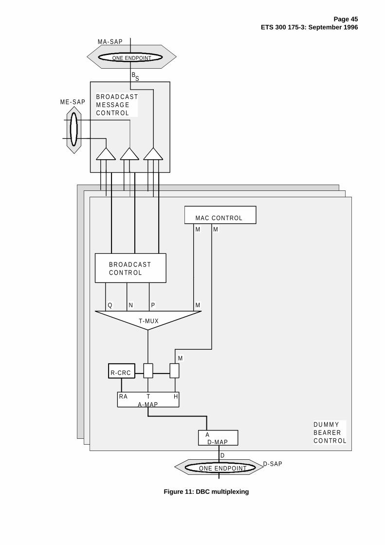
Page 45ETS 300 175-3: September 1996
R-CRC
T-MUX
A-MAP
D-MAP
MPNQ
MA-SAP
ME-SAP
A
MM
M
ONE ENDPOINT
HTRA
D-SAPD
ONE ENDPOINT
MAC CONTROL
BS
B R O A D C A S TM E SS A G EC O N TR O L
B R O A D C A S TC O N TR O L
D U M M YB E A R E RC O N TR O L
Figure 11: DBC multiplexing

Page 46ETS 300 175-3: September 1996
R-CRC
T-MUX
A-MAP
D-MAP
CLS
MPNQ
MA-SAP MB-SAP
ME-SAP
A
MM
M
ONE ENDPOINTONE ENDPOINT
HTRA
D-SAPD
ONE ENDPOINT
C LS
BS
C O N N E CT IO NL ES SM E SS A GEC O N TR O L
B R O AD C A S TME S SA GECO N TR O L
M A CC O N TR OL
B R O AD C A S TC O NT R O L
C O NN E C T IO N L ES SB E AR E RC O NT R O L(sh ort b ea re r)
Figure 12: CBC multiplexing (short)
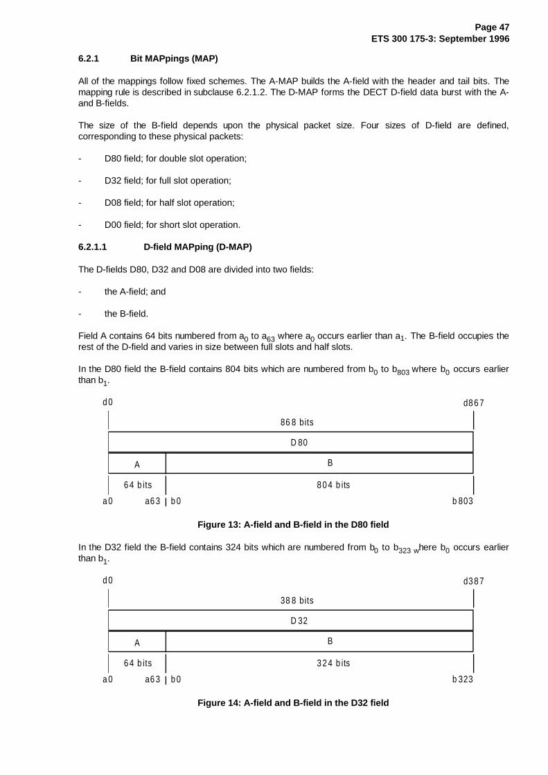
Page 47ETS 300 175-3: September 1996
6.2.1 Bit MAPpings (MAP)
All of the mappings follow fixed schemes. The A-MAP builds the A-field with the header and tail bits. Themapping rule is described in subclause 6.2.1.2. The D-MAP forms the DECT D-field data burst with the A-and B-fields.
The size of the B-field depends upon the physical packet size. Four sizes of D-field are defined,corresponding to these physical packets:
- D80 field; for double slot operation;
- D32 field; for full slot operation;
- D08 field; for half slot operation;
- D00 field; for short slot operation.
6.2.1.1 D-field MAPping (D-MAP)
The D-fields D80, D32 and D08 are divided into two fields:
- the A-field; and
- the B-field.
Field A contains 64 bits numbered from a0 to a63 where a0 occurs earlier than a1. The B-field occupies therest of the D-field and varies in size between full slots and half slots.
In the D80 field the B-field contains 804 bits which are numbered from b0 to b803 where b0 occurs earlierthan b1.
86 8 bits
d 0 d8 6 7
a 0 a6 3 b 0 b 803
A B
D 80
8 0 4 b its6 4 b its
Figure 13: A-field and B-field in the D80 field
In the D32 field the B-field contains 324 bits which are numbered from b0 to b323 where b0 occurs earlierthan b1.
38 8 bits
d 0 d3 8 7
a 0 a6 3 b 0 b 323
A B
D 32
3 2 4 b its6 4 b its
Figure 14: A-field and B-field in the D32 field
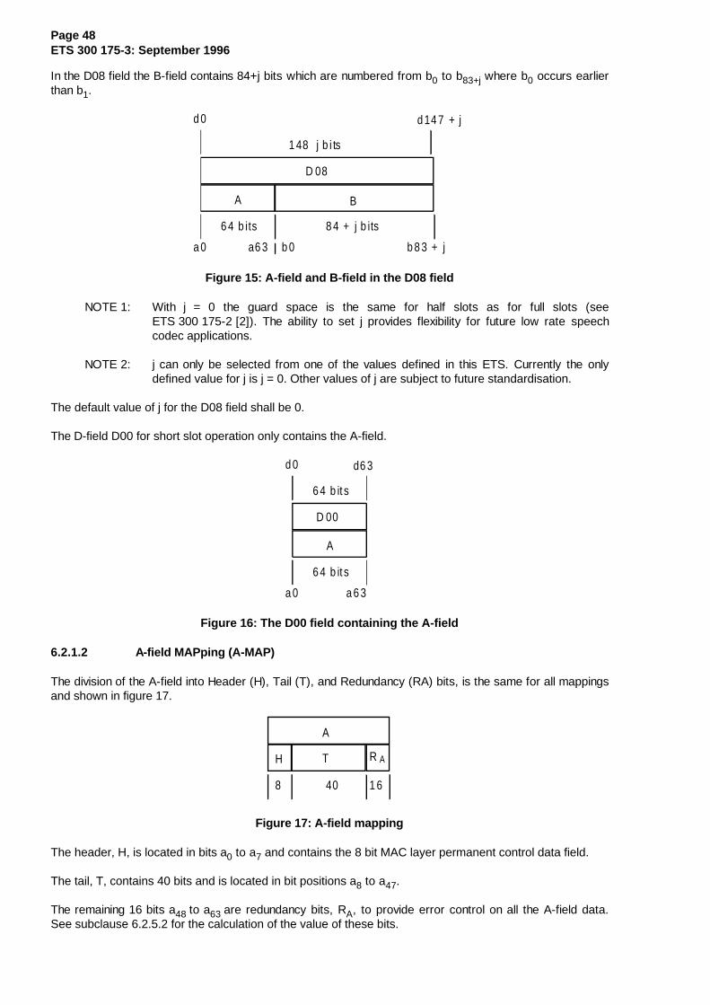
Page 48ETS 300 175-3: September 1996
In the D08 field the B-field contains 84+j bits which are numbered from b0 to b83+j where b0 occurs earlierthan b1.
1 48 j b i ts
d 0 d 14 7 + j
a 0 a6 3 b 0 b 8 3 + j
A B
D 08
8 4 + j b its6 4 b its
Figure 15: A-field and B-field in the D08 field
NOTE 1: With j = 0 the guard space is the same for half slots as for full slots (seeETS 300 175-2 [2]). The ability to set j provides flexibility for future low rate speechcodec applications.
NOTE 2: j can only be selected from one of the values defined in this ETS. Currently the onlydefined value for j is j = 0. Other values of j are subject to future standardisation.
The default value of j for the D08 field shall be 0.
The D-field D00 for short slot operation only contains the A-field.
6 4 b it s
d 0 d6 3
a 0 a 6 3
A
D 00
6 4 b it s
Figure 16: The D00 field containing the A-field
6.2.1.2 A-field MAPping (A-MAP)
The division of the A-field into Header (H), Tail (T), and Redundancy (RA) bits, is the same for all mappingsand shown in figure 17.
A
TH R A
8 40 1 6
Figure 17: A-field mapping
The header, H, is located in bits a0 to a7 and contains the 8 bit MAC layer permanent control data field.
The tail, T, contains 40 bits and is located in bit positions a8 to a47.
The remaining 16 bits a48 to a63 are redundancy bits, RA, to provide error control on all the A-field data.See subclause 6.2.5.2 for the calculation of the value of these bits.

Page 49ETS 300 175-3: September 1996
By definition the header field always contains the MAC control information.
The tail carries data from several logical channels, using the T-MUX algorithm defined in subclause 6.2.2.1.
6.2.1.3 B-field MAPping (B-MAP)
For the B-field two mappings exist, a protected format and an unprotected format. With the unprotectedformat the 4 bit X-field at the end of the B-field contains the only redundancy bits in the B-field.
Unprotected formats: in the unprotected double slot format the mapping of the A-field and B-field ontothe D80-field of physical packets P80 is shown in figure 18 and described as:
80 4
A B
d a tada ta R A
4 8 1 6
64
X
80 0 4
: 0 6 4
d = ai ib - 6 4i :
Figure 18: Unprotected B-field format (double slot)
In the unprotected full slot format the fields A and B are mapped onto the D32-field of physical packetsP32 as follows:
32 4
A B
d a tada ta R A
4 8 1 6
64
X
32 0 4
: 0 < i < 6 36 4 < i < 3 87
d = ai ib - 6 4i :
Figure 19: Unprotected B-field format (full slot)
In the unprotected half slot format the mapping of the A-field and B-field onto the D08-field of physicalpackets P08 is shown in figure 20 and described as:
84 + j
A B
d atada ta R A
48 1 6
64
X
8 0 + j 4
: 0 < i < 6 364 < i < 1 4 7 + j
d = ai ib - 6 4i :
Figure 20: Unprotected B-field format (half slot)

Page 50ETS 300 175-3: September 1996
Protected formats: the protected formats divide the B-field into subfields. The last 4 bits are always theX-field. The other bits are divided into subfields of 80 bit length, where the first subfield starts with the firstbit in the B-field. The subfields are numbered B0, B1, B2 etc. The last subfield before the X-field may havea smaller length than 80 bits. The bit bki from the Bk subfield corresponds to the bit b(80k+i) of the B-field.
All 80 bit subfields consist of a 64 bit data block followed by 16 CRC bits (RBj-fields). In all protectedformats the 80 bit subfield B0 is placed in the same relative position to the synchronisation word and startswith the 65th bit of the physical channel's D-field.
Figure 21 shows the protected double slot format, which is described as:
di = ai : 0 ≤ i ≤ 63b0i - 64 : 64 ≤ i ≤ 143b1i - 144 : 144 ≤ i ≤ 223b2i - 224 : 224 ≤ i ≤ 303b3i - 304 : 304 ≤ i ≤ 383b4i - 384 : 384 ≤ i ≤ 463b5i - 464 : 464 ≤ i ≤ 543b6i - 544 : 544 ≤ i ≤ 623b7i - 624 : 624 ≤ i ≤ 703b8i - 704 : 704 ≤ i ≤ 783b9i - 784 : 784 ≤ i ≤ 863xi - 864 : 864 ≤ i ≤ 867
data RA data data data data data data data data da ta da ta
48 16 64 16 64 16 64 16 64 16 64 16 64 1 6 64 16 64 1 6 64 16 64 16 4
XRB 0
RB 1
R R R R R R R RB 2 B 3 B 4 B 5 B 6 B 7 B 8 B 9
A B0 B1 B2 B3 B4 B5 B6 B 7 B8 B9
A B
64 804
X
Figure 21: Protected B-field format (double slot)
For the protected full slot format a more detailed mapping is shown in figure 22 and described as follows:
di = ai : 0 ≤ i ≤ 63b0i - 64 : 64 ≤ i ≤ 143b1i - 144 : 144 ≤ i ≤ 223b2i - 224 : 224 ≤ i ≤ 303b3i - 304 : 304 ≤ i ≤ 383xi - 384 : 384 ≤ i ≤ 387
data RA data data data data
48 16 64 16 64 16 64 16 64 16
RB 0
RB 1
R RB 2 B 3
A B0 B1 B2 B3
A
64
4
X
X
324
B
Figure 22: Protected B-field format (full slot)
With a B-field length of 84 + j bits in half slot mode, a subfield B1 only exists for j > 0. The use of this fieldin the protected half slot format is undefined. Keeping this field allows the unprotected and the protectedformat to have the same size. Therefore, for a chosen j the X-field is in the same position in both formats.This allows the same X-field procedure to be used for measuring the performance of the physical channelin both protected and unprotected half slot formats.
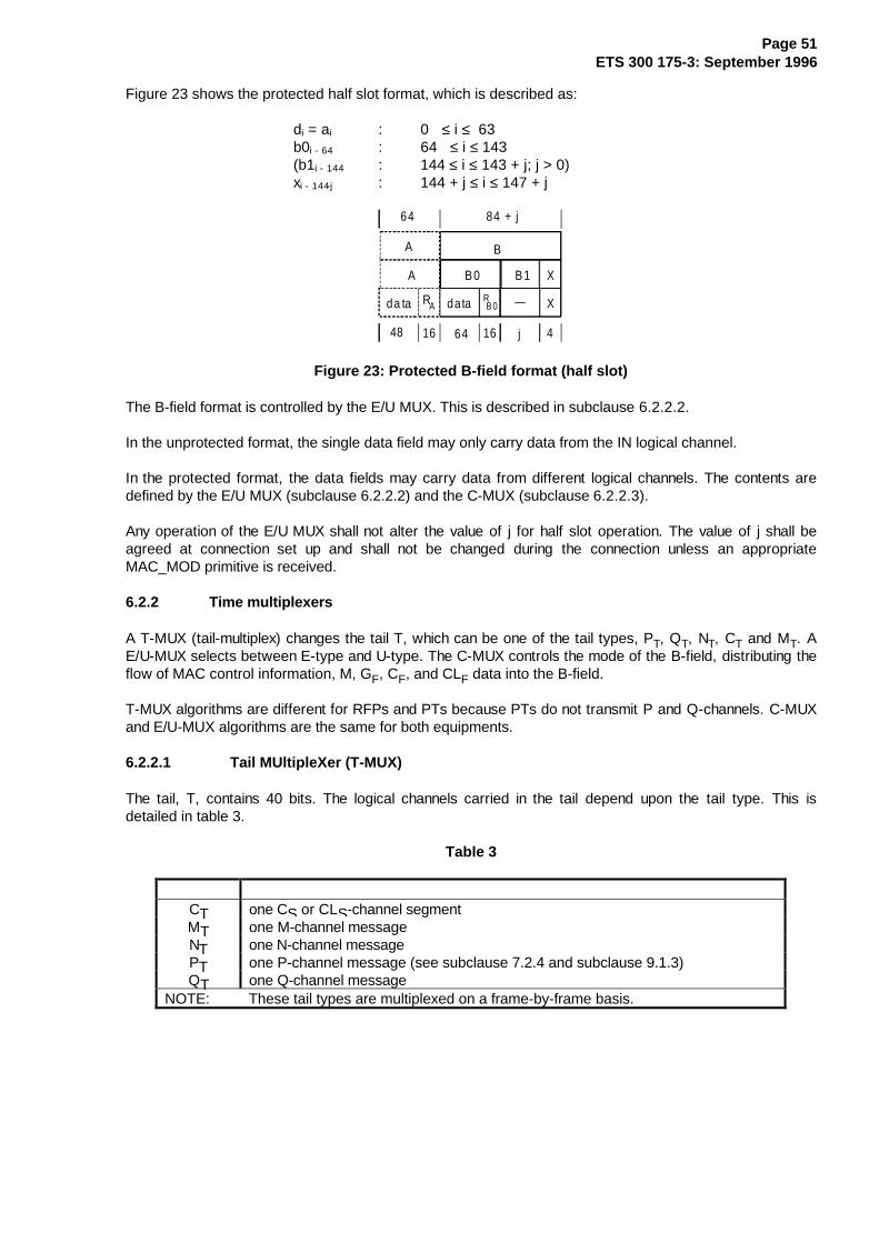
Page 51ETS 300 175-3: September 1996
Figure 23 shows the protected half slot format, which is described as:
di = ai : 0 ≤ i ≤ 63b0i - 64 : 64 ≤ i ≤ 143(b1i - 144 : 144 ≤ i ≤ 143 + j; j > 0)xi - 144-j : 144 + j ≤ i ≤ 147 + j
da ta RA data
48 16 64 16 j
RB 0
A B0 B1
A
64
4
X
X
84 + j
B
Figure 23: Protected B-field format (half slot)
The B-field format is controlled by the E/U MUX. This is described in subclause 6.2.2.2.
In the unprotected format, the single data field may only carry data from the IN logical channel.
In the protected format, the data fields may carry data from different logical channels. The contents aredefined by the E/U MUX (subclause 6.2.2.2) and the C-MUX (subclause 6.2.2.3).
Any operation of the E/U MUX shall not alter the value of j for half slot operation. The value of j shall beagreed at connection set up and shall not be changed during the connection unless an appropriateMAC_MOD primitive is received.
6.2.2 Time multiplexers
A T-MUX (tail-multiplex) changes the tail T, which can be one of the tail types, PT, QT, NT, CT and MT. AE/U-MUX selects between E-type and U-type. The C-MUX controls the mode of the B-field, distributing theflow of MAC control information, M, GF, CF, and CLF data into the B-field.
T-MUX algorithms are different for RFPs and PTs because PTs do not transmit P and Q-channels. C-MUXand E/U-MUX algorithms are the same for both equipments.
6.2.2.1 Tail MUltipleXer (T-MUX)
The tail, T, contains 40 bits. The logical channels carried in the tail depend upon the tail type. This isdetailed in table 3.
Table 3
CT one CS or CLS-channel segmentMT one M-channel messageNT one N-channel messagePT one P-channel message (see subclause 7.2.4 and subclause 9.1.3)QT one Q-channel message
NOTE: These tail types are multiplexed on a frame-by-frame basis.

Page 52ETS 300 175-3: September 1996
6.2.2.1.1 T-MUX algorithm for RFP transmissions
The DECT RFPs support a multiframe structure of 16 frames duration. Both frame and multiframe timingshall be synchronised for all RFPs of one DECT fixed system.
The 16 frames in one multiframe are numbered from frame 0 to frame 15. Once every multiframe, aspecial tail identification is sent in the header, H, to mark frame number 8 of the multiframe.
In all odd frames the tail contains either MT, CT or NT. The applied "MT, CT, NT" priority scheme means:
- MT type tails have priority over;
- CT type tails which have priority over the;
- NT type tails.
In frames {0,2,4,6,10,12} a "PT, NT" priority scheme is used:
- PT type tails have priority over the NT type tails.
The tail of frame 14 is reserved for NT ("NT" priority scheme) and the tail of frame 8 is reserved for QTinformation ("QT" scheme).
The resulting algorithm is given in table 4.
Table 4
Frame Priority scheme Frame Priority scheme0 PT, NT 1 MT, CT, NT
2 PT, NT 3 MT, CT, NT
4 PT, NT 5 MT, CT, NT
6 PT, NT 7 MT, CT, NT
8 QT 9 MT, CT, NT
10 PT, NT 11 MT, CT, NT
12 PT, NT 13 MT, CT, NT
14 NT 15 MT, CT, NT
Exceptions: When responding to a "bearer request" message or during bearer release, theFT may insert an MT tail in an even numbered frame. These are the onlyexceptions.
The following throughput capacities are achieved:(fpmf = frames per multiframe):
CT: higher layer control 0 - 2 kbit/s 0 - 8 fpmf;MT: MAC layer control 0 - 2 kbit/s 0 - 8 fpmf;
NT: identities information 0,25 - 3,75 kbit/s 1 - 15 fpmf;lower limit, excluding exceptions as above 0,25 kbit/s 1 fpmf;
PT: paging 0 - 1,5 kbit/s 0 - 6 fpmf;
QT: system information, excluding exceptions asabove 0,25 kbit/s 1 fpmf.

Page 53ETS 300 175-3: September 1996
6.2.2.1.2 T-MUX algorithm for PT transmissions
The algorithm shown in table 5 is used by PTs for all traffic bearers in connection oriented services:
Table 5
Frame Priority scheme Frame Priority scheme0 MT, CT, NT 1 NT
2 MT, CT, NT 3 NT
4 MT, CT, NT 5 NT
6 MT, CT, NT 7 NT
8 MT, CT, NT 9 NT
10 MT, CT, NT 11 NT
12 MT, CT, NT 13 NT
14 MT, CT, NT 15 NT
Exceptions: The transmission of a "bearer request" or a "bearer release" from a PT may usean MT tail and this may be placed in any frame (see subclauses 10.5 and 10.7).
The following throughput capacities are achieved(fpmf = frames per multi-frame):
NT: identities information 0,25 - 3,75 kbit/s 1 - 15 fpmf;
CT: higher layer control 0 - 2 kbit/s 0 - 8 fpmf;MT: MAC layer control 0 - 2 kbit/s 0 - 8 fpmf;
NT: identities information 2 - 4 kbit/s 8 - 16 fpmf;lower limit, excluding exceptions as above 2 kbit/s 8 fpmf.
Connectionless uplink services and requests for a BMC service always start with a MT message in the firstPT transmission (see subclause 7.2.5.6). Only for connectionless uplink services a second transmissionmay occur. This second transmission uses a CT tail when a CLS segment is carried and a MT tailotherwise.
6.2.2.2 B-field control multiplexer (E/U-MUX)
The E/U MUX switches the B-field between two types of multiplex, the E-type and the U-type.
1) E-type:
- for traffic bearers the B-field is used to carry M-channel data and/or CF-channel data and/orGF-channel data. For connectionless bearers the B-field is used to carry M-channel data and/orCLF-channel data.
2) U-type:
- the B-field is used to carry either IN-channel data or IP-channel data, or SIN or SIP -channel data.
The E/U MUX operates on a frame-by-frame basis in response to immediate traffic demands. The chosenmultiplex for each frame is indicated with the BA bits in the A-field header. E-type multiplex has priorityover U-type multiplex.

Page 54ETS 300 175-3: September 1996
The B-field multiplexes are defined in table 6.
Table 6
B-field multiplex B-field LogicalD80-field D32-field D08-field E/U format channel
E80
U80aU80b
E32
U32aU32b
U08aU08b
E
UU
Protected
UnprotectedProtected
C-MUX
IN or SINIP or SIP
The E-type multiplex always uses the protected B-field format. The possible modes of the E-type multiplexare defined by the C-MUX (see subclause 6.2.2.3).
The U-type multiplex in connection oriented services may use either the protected B-field format or theunprotected B-field format. This choice is defined at connection establishment for all bearers belonging tothat connection, and it corresponds to the logical channel required for the chosen service, IN or IP. Thechosen format is maintained until it is re-negotiated or the connection ends.
6.2.2.3 B-field mode multiplexer (C-MUX)
6.2.2.3.1 Double slot and full slot modes
For double slot and full slot mode all B-subfields are used for control. The following types of informationhave to be multiplexed:
- higher layer control from the CF or CLF logical channel;
- MAC layer connection related signalling;
- higher layer information from the GF logical channel; and
- MAC layer control to describe the contents of the subfields.
All extended MAC control and GF segments carried in the B-subfields have a header with a bit indicating ifthe next subfield in the same databurst contains an extended MAC control or GF segment, or whether itcontains higher layer control.

Page 55ETS 300 175-3: September 1996
For double slot operation the modes are given in table 7.
Table 7
Subfield B0 B1 B2 B3 B4 B5 B6 B7 B8 B9
C/O CF CF CF CF CF CF CF CF CF CF
Mode 0C/L CLF CLF CLF CLF CLF CLF CLF CLF CLF CLF
C/O M/M+GF CF CF CF CF CF CF CF CF CF
Mode 1C/L M CLF CLF CLF CLF CLF CLF CLF CLF CLF
C/O M/M+GF M/M+GF CF CF CF CF CF CF CF CF
Mode 2C/L M M CLF CLF CLF CLF CLF CLF CLF CLF
C/O M/M+GF M/M+GF M/M+GF CF CF CF CF CF CF CF
Mode 3C/L M M M CLF CLF CLF CLF CLF CLF CLF
C/O M/M+GF M/M+GF M/M+GF M/M+GF CF CF CF CF CF CF
Mode 4C/L M M M M CLF CLF CLF CLF CLF CLF
C/O M/M+GF M/M+GF M/M+GF M/M+GF M/M+GF CF CF CF CF CF
Mode 5C/L M M M M M CLF CLF CLF CLF CLF
C/O M/M+GF M/M+GF M/M+GF M/M+GF M/M+GF M/M+GF CF CF CF CF
Mode 6C/L M M M M M M CLF CLF CLF CLF
C/O M/M+GF M/M+GF M/M+GF M/M+GF M/M+GF M/M+GF M/M+GF CF CF CF
Mode 7C/L M M M M M M M CLF CLF CLF
C/O M/M+GF M/M+GF M/M+GF M/M+GF M/M+GF M/M+GF M/M+GF M/M+GF CF CF
Mode 8C/L M M M M M M M M CLF CLF
C/O M/M+GF M/M+GF M/M+GF M/M+GF M/M+GF M/M+GF M/M+GF M/M+GF M/M+GF M/M+GF
Mode 9C/L M M M M M M M M M MC/O M/M+GF M/M+GF M/M+GF M/M+GF M/M+GF M/M+GF M/M+GF M/M+GF M/M+GF M/M+GF
Mode 10C/L M M M M M M M M M M
For double slot operation the A-field header coding (BA bits) shall distinguish between :
- E-type, mode 0;
- E-type, modes 1 - 9; and
- E-type, mode 10.

Page 56ETS 300 175-3: September 1996
For full slot operation the modes given in table 8 are allowed.
Table 8
su bfield B0 B 1 B 2 B3
M o de 0C /O
C /L
CF
M
C L F
CF CF CF
M /M + GF
C L F C L F C L F
M o de 1C /O
C /L
CF CF CF
C L F C L F C L F
M o de 2C /O
C /L
CF CF
C L F C L F
M o de 3C /O
C /L
CF
C L F
M o de 4C /O
C /L
M /M + GF M /M +GF
M /M + GF M /M +GF M /M + GF
M /M + GF M /M +GF M /M + GF M /M +GF
M M
M M M
M M M M
For full slot operation the A-field header coding (BA bits) will distinguish between:
- E-type, mode 0;
- E-type, modes 1 - 3; and
- E-type, mode 4.
For Connection Oriented services (C/O) and when in E mode, the following priority scheme shall be usedto fill the four B-subfields:
1) Release: bearer release messages for this bearer may be transmitted and may be placed in all4 subfields.
2) Retransmissions of C F: for retransmissions of B-fields containing CF, the same mode shall beused.
3) Bearer quality control In an asymmetric connection: in an asymmetric connection a"MAC-Mod2-ACKs" message (subclause 7.3.5.4) may be placed in the subfield B0.
4) Other MAC layer control (excluding MAC_Dummy): this may be placed in the remainingsubfields. The subfields are used in the following order of preference, B0, B1, B2, B3.
5) New CF data: any remaining subfields may be used for CF data. The subfields are used in thefollowing order of preference, B3, B2, B1, B0. However, the sequence of data through the MC SAPshall be B0, B1, B2, B3.
6) New GF data: this may be placed in any subfield that has not yet been used. The order of usage ofsubfields and the sequence of data segments through the MC SAP is not specified.
7) Null message: this shall be used to fill any subfields still empty.

Page 57ETS 300 175-3: September 1996
In connectionless services new CLF segments have priority over MAC control.
6.2.2.3.2 Half slot modes
For half slot mode only one B-subfield is available for control. The following types of information have to bemultiplexed:
- higher layer control from the CF or CLF logical channel; and
- MAC layer connection related signalling.
NOTE: As multi-bearer half slots are prohibited, asymmetric connections are not possible, andso no GF-channel is used.
Only one E-type mapping exists.
The A-field header coding will distinguish between:
- E-type, mode 0; and
- E-type, mode 1.
Mode 0: the E-type databurst carries CF or CLF control;
Mode 1: the E-type databurst carries extended MAC control.
When in E mode, the following priority scheme shall be used to fill the B0 subfield in connection orientedservices:
1) Release: bearer release messages for this bearer may be placed in B0.
2) Retransmissions of CF .
3) MAC layer control (excluding MAC_dummy).
4) New CF data .
5) MAC_dummy: U-type information should normally be sent in preference to this.
For connectionless services, CLF data has priority over MAC control.
6.2.3 Encryption
Encryption is a privacy mechanism which may be provided to encrypt all C, I, and GF-channel data of aconnection oriented call. The key stream generator KSG in the MBC produces the encryption sequencewhich are XOR'd with the original data in the TBC's encryption entity.
NOTE 1: When enabled also M-channel data transmitted in the B-field is encrypted.
NOTE 2: Error control (R-CRC and X-CRC bits) are never encrypted.
Before activating the encryption mechanism for the first time, the DLC provides the MBC with a secretencryption key. This key is loaded into the key stream generator KSG.
Enabling and disabling of encryption is ordered by the DLC. The MBC is responsible for switching betweenencryption mode and clear mode. The actual encryption mode of the connection controlled by the MBCshall be the same for all established bearers of this connection.
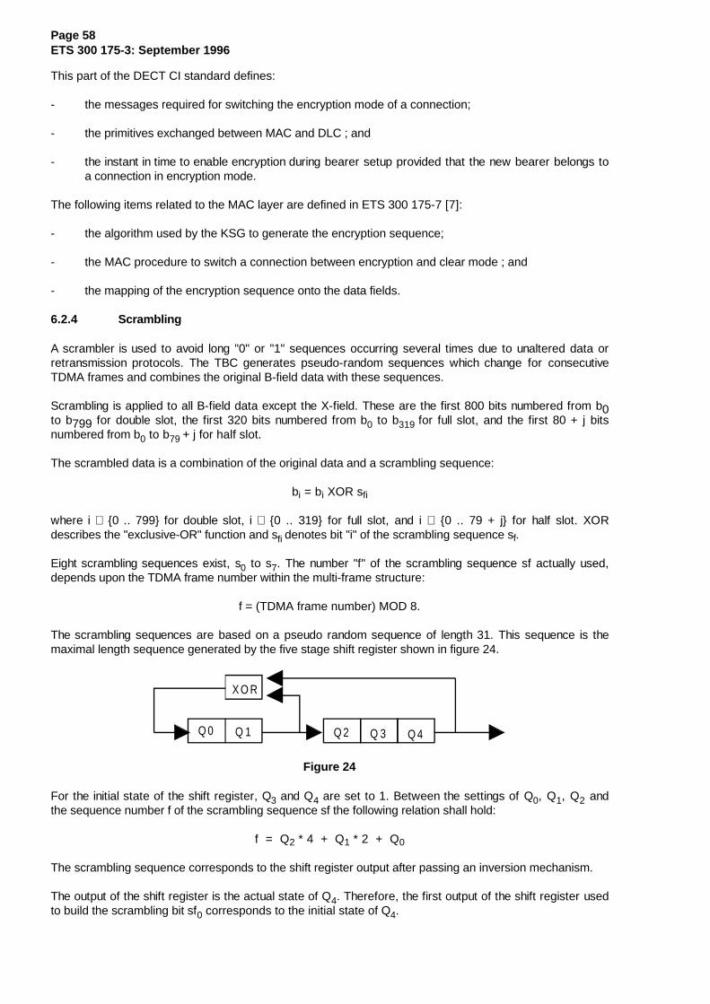
Page 58ETS 300 175-3: September 1996
This part of the DECT CI standard defines:
- the messages required for switching the encryption mode of a connection;
- the primitives exchanged between MAC and DLC ; and
- the instant in time to enable encryption during bearer setup provided that the new bearer belongs toa connection in encryption mode.
The following items related to the MAC layer are defined in ETS 300 175-7 [7]:
- the algorithm used by the KSG to generate the encryption sequence;
- the MAC procedure to switch a connection between encryption and clear mode ; and
- the mapping of the encryption sequence onto the data fields.
6.2.4 Scrambling
A scrambler is used to avoid long "0" or "1" sequences occurring several times due to unaltered data orretransmission protocols. The TBC generates pseudo-random sequences which change for consecutiveTDMA frames and combines the original B-field data with these sequences.
Scrambling is applied to all B-field data except the X-field. These are the first 800 bits numbered from b0to b799 for double slot, the first 320 bits numbered from b0 to b319 for full slot, and the first 80 + j bitsnumbered from b0 to b79 + j for half slot.
The scrambled data is a combination of the original data and a scrambling sequence:
bi = bi XOR sfi
where i ∈ {0 .. 799} for double slot, i ∈ {0 .. 319} for full slot, and i ∈ {0 .. 79 + j} for half slot. XORdescribes the "exclusive-OR" function and sfi denotes bit "i" of the scrambling sequence sf.
Eight scrambling sequences exist, s0 to s7. The number "f" of the scrambling sequence sf actually used,depends upon the TDMA frame number within the multi-frame structure:
f = (TDMA frame number) MOD 8.
The scrambling sequences are based on a pseudo random sequence of length 31. This sequence is themaximal length sequence generated by the five stage shift register shown in figure 24.
X O R
Q 0 Q 1 Q 2 Q 3 Q 4
Figure 24
For the initial state of the shift register, Q3 and Q4 are set to 1. Between the settings of Q0, Q1, Q2 andthe sequence number f of the scrambling sequence sf the following relation shall hold:
f = Q2 * 4 + Q1 * 2 + Q0
The scrambling sequence corresponds to the shift register output after passing an inversion mechanism.
The output of the shift register is the actual state of Q4. Therefore, the first output of the shift register usedto build the scrambling bit sf0 corresponds to the initial state of Q4.
Page 59ETS 300 175-3: September 1996
The inversion mechanism has two modes, the shift register output passes through non inverted or inverted.The inversion mechanism toggles from one mode to the other mode when the shift register switches to thestate following the all one state. The toggle mode is preset to invert the first output of the shift register.
Scrambling of the B-field is mandatory and shall always be applied, even when encryption is active.
6.2.5 Error control
The MAC layer provides error control for all logical channels, using a combination of two CyclicRedundancy Codes (CRC):
- R-CRC; a 16-bit CRC;
- X-CRC; a 4-bit CRC.
6.2.5.1 R-CRC overview
The R-CRC is used to provide the main MAC layer error control. The MAC layer calculates 16 redundancybits over several fixed length data blocks:
- all A-fields;
- all B-subfields in protected format.
In each case, the redundancy bits are appended to the data blocks and allow a redundancy check in thereceiver. In the different mapping schemes given in subclause 6.2.1.3, the fields for transmitting the CRCbits are denoted as RA and RB0 ... RB3. The procedure for calculating the 16 CRC bits and the rule tocheck a received data block with its CRC bits is defined in subclause 6.2.5.2.
Data transmitted from all logical channels except the IN-channel is located in data blocks to which these 16CRC bits are appended (see mapping schemes in subclause 6.2.1). This allows the receiver to detecterrors in all N, Q, BS, CS, CF, CLS, CLF, SIP, IP, GF and M-channel data.
For N, Q, BS, CLS, CLF, SIP, M and GF-channel data and IP-channel data (when in the IP_error_detectionservice) only error detection capability is provided. No MAC layer retransmission scheme is applied for thisdata.
For CS and CF-channel data, a MAC layer retransmission scheme is defined in order to correcttransmission errors. A numbering scheme allows successive data transmissions on these channels to bedistinguished. This allows repetition (retransmission) of the same data several times until the transmittergets an acknowledgement from the data receiver or the transmitter stops retransmitting the data. Theretransmission process is described in subclause 10.8.
For the IP_error_correction service the MAC layer provides a retransmission scheme for IP data.Retransmissions are done for each bearer independently. The receiving side requests that the sending sidetransmits the last packet again until no errors are detected or, until a timer expires. When the timer expiresthat packet is discarded. Data passed to the upper layer is almost free from errors. This error correctionscheme is called the MOD-2 retransmission scheme for IP data, and described in subclause 10.8.2.
6.2.5.2 R-CRC generation and checking
All m = 64 bit A-fields and all m = 80 bit B-subfields (see subclause 6.2.1.3) contain n data bits and 16check bits. Therefore the data block length n is m - 16. The 16 check bits are appended to the n data bits.For encoding, the n data bits shall be considered to be the coefficients of a polynomial having terms fromxm-1 down to x16. If the m bits of one protected field are transmitted in ascending order (r0,r1,...,rm-1) thepolynomial is built as:
r0 x xm-1 + r1 x xm-2 + ... + rn-1 x x16
Page 60ETS 300 175-3: September 1996
This polynomial is divided by the generating polynomial:
g(x) = x16 + x10 + x8 + x7 + x3 + 1 = 202'611 (oct)
The 16 check bits shall be the coefficients of the terms from x15 to x0 in the remainder polynomial, foundat the completion of the division. The remainder polynomial has the form:
rn x x15 + rn+1 x x14 + ... + rm-1 x x0
The last check bit (coefficient rm-1 of the x0 term in the remainder polynomial) is finally inverted.
In the resulting m = n+16 bit codeword, the leading n bits correspond to the original data bits.
For error detecting it has to be ensured that the received m-bit codeword is a valid codeword. Again the mbits can be considered to be the coefficients of a polynomial having terms from xm-1 down to x0. If the mbits of one protected field are received in ascending order (r0,r1,...,rm-1) the polynomial is built as:
r0 x xm-1 + r1 x xm-2 + ... + rm-1 x x0
After inverting the coefficient rm-1 of the x0 term the generator polynomial g(x) divides all valid codewords.
6.2.5.3 X-CRC overview
For error control of B-field data a limited error detection scheme is always applied, even for unprotectedB-field formats. This is the only protection that is applied to the IN logical channel. The MAC layercalculates 4 redundancy bits from selected B-field data bits. These four bits are transmitted in the X-field.The X-field occupies the last four bits of the B-field in all multiplexes. The X-field allows a redundancycheck in the receiver. The procedure for calculating and checking the X-field bits is defined insubclause 6.2.5.4.
6.2.5.4 X-CRC generation and checking
The X-field consists of the last four bits of the B-field. It is used to test channel quality and to detect slidingcollisions. Therefore, a CRC check is done over a selected number of scrambled B-field bits.
The overall number of test bits is m. These m bits include the four X-field bits. The number m is differentfor half slot, for full slot, and for double slot:
- m = 84 + j for half slot;
- m = 84 for full slot;
- m = 164 for double slot.
With a test bit assignment of (r0,r1, ... ,rm-1) the mapping of the test bits onto the B-field is the following:
ri = bi ; 0 ≤ i ≤ 83 + j for half slot,ri = bi + 48 ; 0 ≤ i ≤ 15
bi + 96 ; 16 ≤ i ≤ 31bi + 144 ; 32 ≤ i ≤ 47bi + 192 ; 48 ≤ i ≤ 63bi + 240 ; 64 ≤ i ≤ 83 for full slot,
ri = bi + 64 ; 0 ≤ i ≤ 15bi + 128 ; 16 ≤ i ≤ 31bi + 192 ; 32 ≤ i ≤ 47bi + 256 ; 48 ≤ i ≤ 63bi + 320 ; 64 ≤ i ≤ 79bi + 384 ; 80 ≤ i ≤ 95bi + 448 ; 96 ≤ i ≤ 111bi + 512 ;112 ≤ i ≤ 127
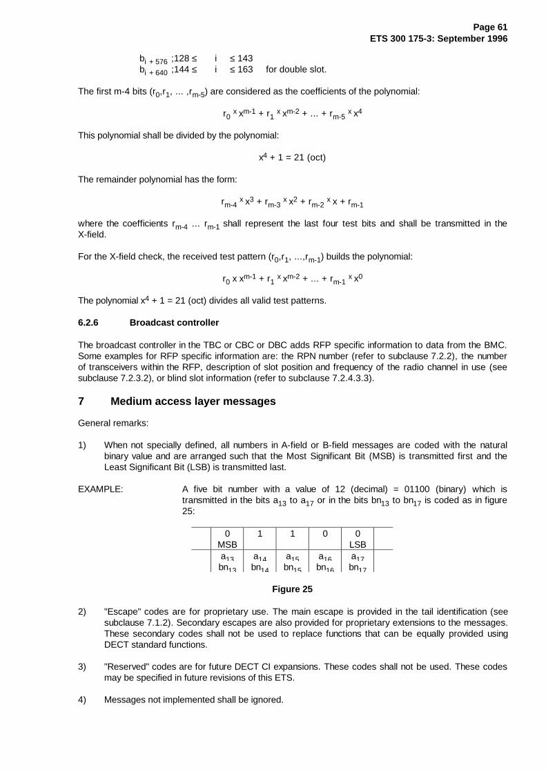
Page 61ETS 300 175-3: September 1996
bi + 576 ;128 ≤ i ≤ 143bi + 640 ;144 ≤ i ≤ 163 for double slot.
The first m-4 bits (r0,r1, ... ,rm-5) are considered as the coefficients of the polynomial:
r0 x xm-1 + r1 x xm-2 + ... + rm-5 x x4
This polynomial shall be divided by the polynomial:
x4 + 1 = 21 (oct)
The remainder polynomial has the form:
rm-4 x x3 + rm-3 x x2 + rm-2 x x + rm-1
where the coefficients rm-4 ... rm-1 shall represent the last four test bits and shall be transmitted in theX-field.
For the X-field check, the received test pattern (r0,r1, ...,rm-1) builds the polynomial:
r0 x xm-1 + r1 x xm-2 + ... + rm-1 x x0
The polynomial x4 + 1 = 21 (oct) divides all valid test patterns.
6.2.6 Broadcast controller
The broadcast controller in the TBC or CBC or DBC adds RFP specific information to data from the BMC.Some examples for RFP specific information are: the RPN number (refer to subclause 7.2.2), the numberof transceivers within the RFP, description of slot position and frequency of the radio channel in use (seesubclause 7.2.3.2), or blind slot information (refer to subclause 7.2.4.3.3).
7 Medium access layer messages
General remarks:
1) When not specially defined, all numbers in A-field or B-field messages are coded with the naturalbinary value and are arranged such that the Most Significant Bit (MSB) is transmitted first and theLeast Significant Bit (LSB) is transmitted last.
EXAMPLE: A five bit number with a value of 12 (decimal) = 01100 (binary) which istransmitted in the bits a13 to a17 or in the bits bn13 to bn17 is coded as in figure25:
0MSB
1 1 0 0LSB
a13bn13
a14bn14
a15bn15
a16bn16
a17bn17
Figure 25
2) "Escape" codes are for proprietary use. The main escape is provided in the tail identification (seesubclause 7.1.2). Secondary escapes are also provided for proprietary extensions to the messages.These secondary codes shall not be used to replace functions that can be equally provided usingDECT standard functions.
3) "Reserved" codes are for future DECT CI expansions. These codes shall not be used. These codesmay be specified in future revisions of this ETS.
4) Messages not implemented shall be ignored.
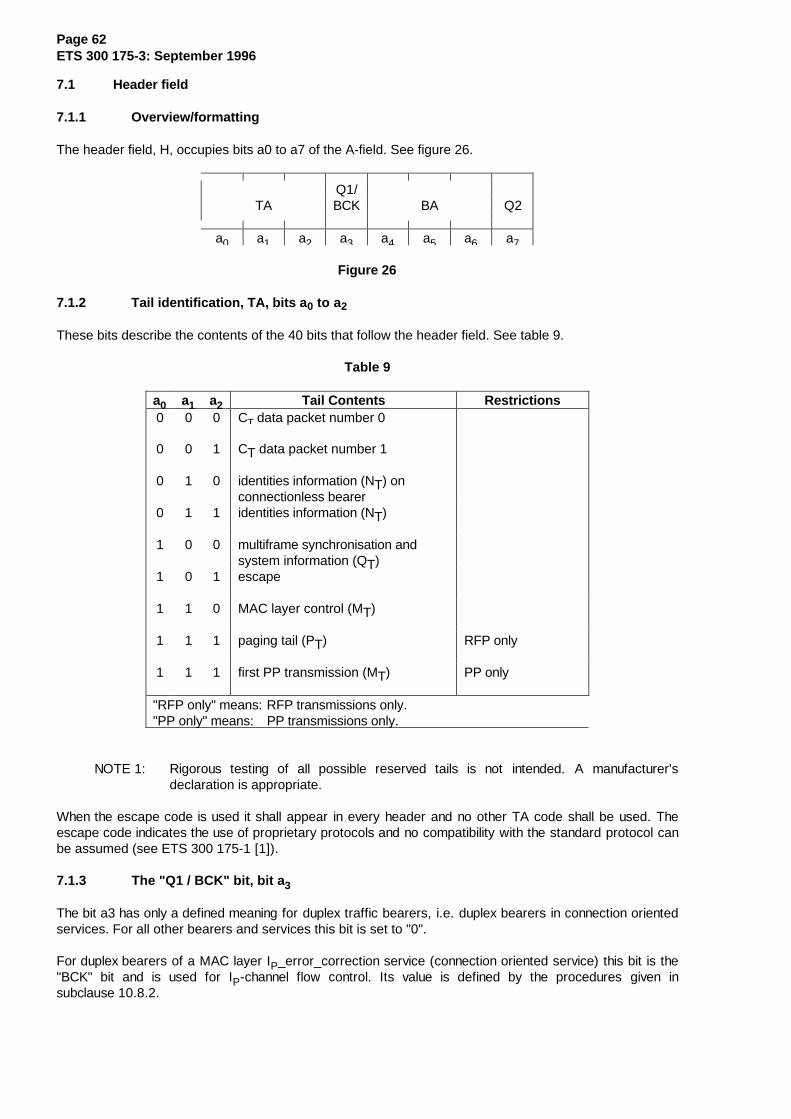
Page 62ETS 300 175-3: September 1996
7.1 Header field
7.1.1 Overview/formatting
The header field, H, occupies bits a0 to a7 of the A-field. See figure 26.
Q1/TA BCK BA Q2
a0 a1 a2 a3 a4 a5 a6 a7
Figure 26
7.1.2 Tail identification, TA, bits a 0 to a2
These bits describe the contents of the 40 bits that follow the header field. See table 9.
Table 9
a0 a1 a2 Tail Contents Restrictions0 0 0 CT data packet number 0
0 0 1 CT data packet number 1
0 1 0 identities information (NT) onconnectionless bearer
0 1 1 identities information (NT)
1 0 0 multiframe synchronisation andsystem information (QT)
1 0 1 escape
1 1 0 MAC layer control (MT)
1 1 1 paging tail (PT) RFP only
1 1 1 first PP transmission (MT) PP only
"RFP only" means: RFP transmissions only."PP only" means: PP transmissions only.
NOTE 1: Rigorous testing of all possible reserved tails is not intended. A manufacturer'sdeclaration is appropriate.
When the escape code is used it shall appear in every header and no other TA code shall be used. Theescape code indicates the use of proprietary protocols and no compatibility with the standard protocol canbe assumed (see ETS 300 175-1 [1]).
7.1.3 The "Q1 / BCK" bit, bit a 3
The bit a3 has only a defined meaning for duplex traffic bearers, i.e. duplex bearers in connection orientedservices. For all other bearers and services this bit is set to "0".
For duplex bearers of a MAC layer IP_error_correction service (connection oriented service) this bit is the"BCK" bit and is used for IP-channel flow control. Its value is defined by the procedures given insubclause 10.8.2.

Page 63ETS 300 175-3: September 1996
For duplex bearers of all the other connection oriented MAC layer services, this bit is the "Q1" bit and usedfor bearer quality control. Its value is defined by the procedures given in subclause 10.8.1.3.
7.1.4 B-field identification, BA, bits a 4 to a6
These bits describe the contents of the B-field that follows the A-field. See table 10.
Table 10
a4 a5 a6 B-field contents0 0 0 U-type, IN, SIN SIP, or IP packet number 0
0 0 1 U-type, IP error detect or IP packet number 1
0 1 0 E-type, all CF or CLF, packet number 0
0 1 1 E-type, all CF, packet number 1
1 0 0 E-type, not all CF or CLF; CF packet number 0
1 0 1 E-type, not all CF; CF packet number 1
1 1 0 E-type, all MAC control (unnumbered)
1 1 1 no B-field
NOTE: Testing of this H-field with all possible T- and B-fields is not intended. A manufacturer'sdeclaration is appropriate.
7.1.5 The "Q2" bit, bit a 7
The bit a7 has only a defined meaning for duplex traffic bearers, i.e. duplex bearers in connection orientedservices. For all other bearers and services this bit is set to "0".
For duplex bearers of connection oriented MAC layer services, this bit is the "Q2" bit and used for bearerquality control and C-channel flow control. Its value is defined by the procedures given insubclause 10.8.1.3 for IN and IP_error_detection services and in subclause 10.8.2.4 forIP_error_correction services.
7.2 Messages in the tail field
7.2.1 Overview
Several different messages may be multiplexed into the tail field, according to the T-MUX algorithm definedin subclause 6.2.2.1. The contents of the tail field are defined for each frame by the tail identification bitsdefined in subclause 7.1.2.
Each tail message has a fixed length of 40 bits. In the following descriptions the mapping of the messageinto the A-field is shown. The first bit of the message always appears in bit position a8 as shown infigure 27:
Head Tail R-CRC
a8 a47
Tail message - 40 bits
Figure 27
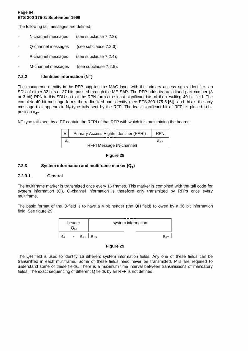
Page 64ETS 300 175-3: September 1996
The following tail messages are defined:
- N-channel messages (see subclause 7.2.2);
- Q-channel messages (see subclause 7.2.3);
- P-channel messages (see subclause 7.2.4);
- M-channel messages (see subclause 7.2.5).
7.2.2 Identities information (N T)
The management entity in the RFP supplies the MAC layer with the primary access rights identifier, anSDU of either 32 bits or 37 bits passed through the ME SAP. The RFP adds its radio fixed part number (8or 3 bit) RPN to this SDU so that the RPN forms the least significant bits of the resulting 40 bit field. Thecomplete 40 bit message forms the radio fixed part identity (see ETS 300 175-6 [6]), and this is the onlymessage that appears in NT type tails sent by the RFP. The least significant bit of RFPI is placed in bitposition a47.
NT type tails sent by a PT contain the RFPI of that RFP with which it is maintaining the bearer.
E Primary Access Rights Identifier (PARI) RPN
a8 a47RFPI Message (N-channel)
Figure 28
7.2.3 System information and multiframe marker (Q T)
7.2.3.1 General
The multiframe marker is transmitted once every 16 frames. This marker is combined with the tail code forsystem information (Q). Q-channel information is therefore only transmitted by RFPs once everymultiframe.
The basic format of the Q-field is to have a 4 bit header (the QH field) followed by a 36 bit informationfield. See figure 29.
headerQH
system information
a8 - a11 a12 a47
Figure 29
The QH field is used to identify 16 different system information fields. Any one of these fields can betransmitted in each multiframe. Some of these fields need never be transmitted. PTs are required tounderstand some of these fields. There is a maximum time interval between transmissions of mandatoryfields. The exact sequencing of different Q fields by an RFP is not defined.

Page 65ETS 300 175-3: September 1996
Table 11
QH SYSTEM INFORMATION MAN FREQ000X static system info Yes 80010 extended RF carriers note 1 80011 fixed part capabilities Yes 80100 extended fixed part capabilities note 2 80101 SARI list contents No 40110 multi-frame number note 3 80111 escape No -1000
to1111
} } Reserved}
MAN = Mandatory transmission (Yes/No).FREQ = Maximum repeat interval in multiframes, if implemented.
NOTE 1: If an extended frequency allocation is used this message shall be transmitted in themultiframe following every transmission of the static system information.
NOTE 2: If extended fixed part capabilities information is available this message shall betransmitted in the multiframe following every transmission of the fixed part capabilitiesinformation.
NOTE 3: If an RFP implements encryption then this message shall be transmitted at least onceevery 8 multiframes.
7.2.3.2 Static system information
7.2.3.2.1 General, Q H = 0, 1 (hex)
This message shall be sent at least once every 8 multiframes. See figure 30.
QH e T000 N SN SP s x M RF-cars spr CN spr PSCN
R c s c
a8 a15 a16 a23 a24 a31 a32 a39 a40 a47
Figure 30
7.2.3.2.2 QH and Normal-Reverse (NR)
NR defines whether the RFP is transmitting in its normal half frame, or whether this is the reversed half ofan asymmetric connection. See table 12.
Table 12
bit a 11 meaning01
"normal" RFP transmit half frame"normal"PP transmit half frame
NOTE: QH and NR are combined to allow easier decoding.
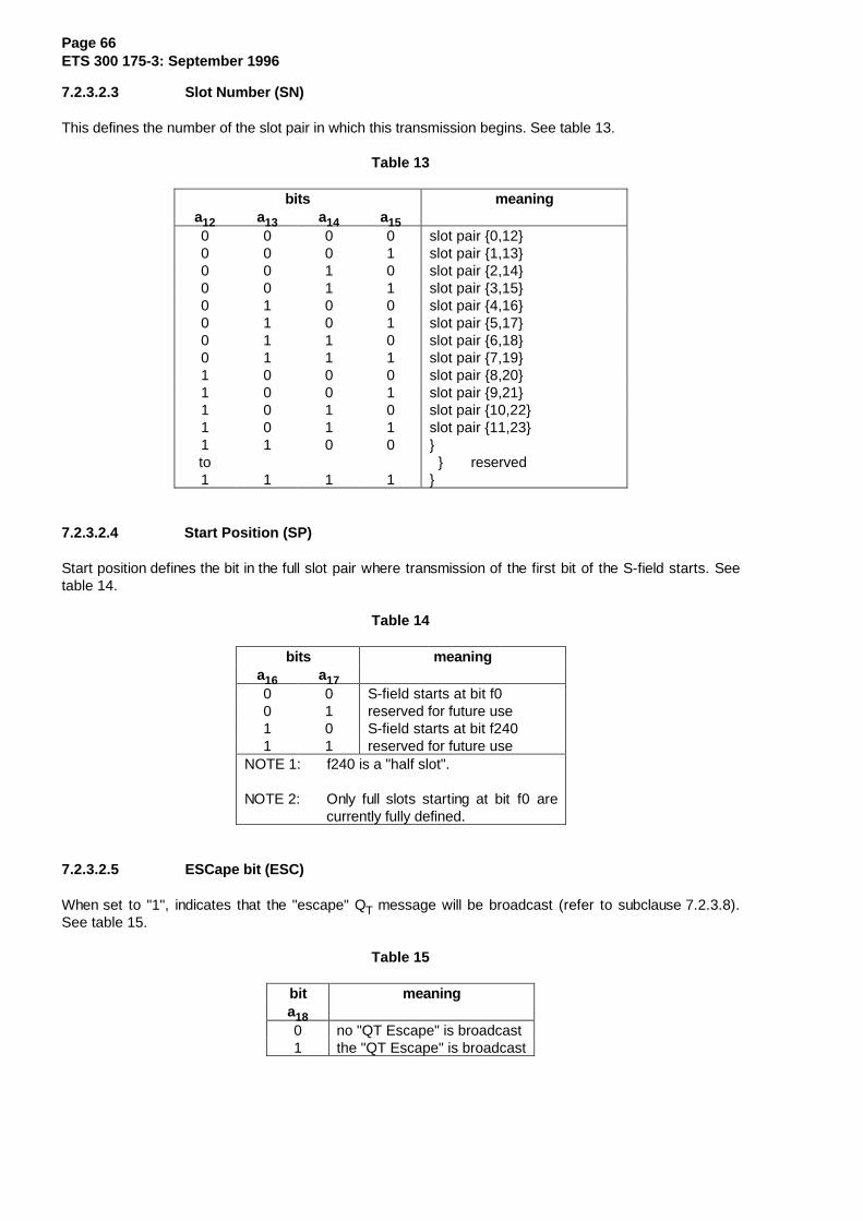
Page 66ETS 300 175-3: September 1996
7.2.3.2.3 Slot Number (SN)
This defines the number of the slot pair in which this transmission begins. See table 13.
Table 13
bits meaninga12 a13 a14 a150 0 0 0 slot pair {0,12}0 0 0 1 slot pair {1,13}0 0 1 0 slot pair {2,14}0 0 1 1 slot pair {3,15}0 1 0 0 slot pair {4,16}0 1 0 1 slot pair {5,17}0 1 1 0 slot pair {6,18}0 1 1 1 slot pair {7,19}1 0 0 0 slot pair {8,20}1 0 0 1 slot pair {9,21}1 0 1 0 slot pair {10,22}1 0 1 1 slot pair {11,23}1to1
1
1
0
1
0
1
} } reserved}
7.2.3.2.4 Start Position (SP)
Start position defines the bit in the full slot pair where transmission of the first bit of the S-field starts. Seetable 14.
Table 14
bits meaninga16 a170 0 S-field starts at bit f00 1 reserved for future use1 0 S-field starts at bit f2401 1 reserved for future use
NOTE 1: f240 is a "half slot".
NOTE 2: Only full slots starting at bit f0 arecurrently fully defined.
7.2.3.2.5 ESCape bit (ESC)
When set to "1", indicates that the "escape" QT message will be broadcast (refer to subclause 7.2.3.8).See table 15.
Table 15
bit meaninga180 no "QT Escape" is broadcast1 the "QT Escape" is broadcast
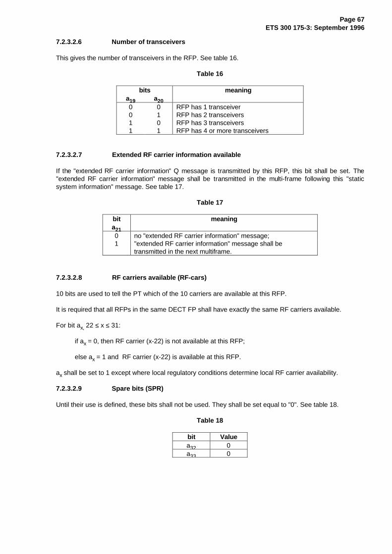
Page 67ETS 300 175-3: September 1996
7.2.3.2.6 Number of transceivers
This gives the number of transceivers in the RFP. See table 16.
Table 16
bits meaninga19 a200 0 RFP has 1 transceiver0 1 RFP has 2 transceivers1 0 RFP has 3 transceivers1 1 RFP has 4 or more transceivers
7.2.3.2.7 Extended RF carrier information available
If the "extended RF carrier information" Q message is transmitted by this RFP, this bit shall be set. The"extended RF carrier information" message shall be transmitted in the multi-frame following this "staticsystem information" message. See table 17.
Table 17
bit meaninga210 no "extended RF carrier information" message;1 "extended RF carrier information" message shall be
transmitted in the next multiframe.
7.2.3.2.8 RF carriers available (RF-cars)
10 bits are used to tell the PT which of the 10 carriers are available at this RFP.
It is required that all RFPs in the same DECT FP shall have exactly the same RF carriers available.
For bit ax, 22 ≤ x ≤ 31:
if ax = 0, then RF carrier (x-22) is not available at this RFP;
else ax = 1 and RF carrier (x-22) is available at this RFP.
ax shall be set to 1 except where local regulatory conditions determine local RF carrier availability.
7.2.3.2.9 Spare bits (SPR)
Until their use is defined, these bits shall not be used. They shall be set equal to "0". See table 18.
Table 18
bit Valuea32 0a33 0

Page 68ETS 300 175-3: September 1996
7.2.3.2.10 Carrier number
This defines the number of the RF carrier of this transmission. See table 19.
Table 19
bits meaninga34 a35 a36 a37 a38 a390 0 0 0 0 0 RF Carrier 00 0 0 0 0 1 RF Carrier 10 0 0 0 1 0 RF Carrier 2
............ etc. ...........0 0 1 0 0 1 RF Carrier 90 0 1 0 1 0 reserved
............ etc. ...........0 0 1 1 1 1 reserved
............ to ...........1 1 1 1 1 1 reserved
7.2.3.11 Spare bits (SPR)
Until their use is defined, these bits shall not be used. They shall be set equal to "0". See table 20.
Table 20
bit Valuea40 0a41 0
7.2.3.2.12 Primary receiver Scan Carrier Number (PSCN)
The PSCN defines the RF carrier on which one receiver will be listening on the next frame when only onereceiver is idle. See table 21.
Table 21
bits meaninga42 a43 a44 a45 a46 a470 0 0 0 0 0 primary scan next on RF Carrier 00 0 0 0 0 1 primary scan next on RF Carrier 10 0 0 0 1 0 primary scan next on RF Carrier 2
............ etc. ...........0 0 1 0 0 1 primary scan next on RF Carrier 90 0 1 0 1 0 reserved
............ etc. ...........0 0 1 1 1 1 reserved
............ to ...........1 1 1 1 1 1 reserved
NOTE: In normal systems the value in the PSCN field may change with each transmission (asPSCN has a 10 frame cycle and Q messages have a 16 frame cycle).

Page 69ETS 300 175-3: September 1996
7.2.3.3 Extended RF carrier information
7.2.3.3.1 General, Q H = 2 (hex)
The transmission of this message is mandatory if a DECT FT is able to transmit on a RF carrier that is notin the set {0,1,2,3,4,5,6,7,8,9}.
All PTs shall be able to understand bits a8 to a11, and bits a42 to a47 inclusive, of this message. Seefigure 31.
QH RF RF 0 0 number of0 0 1 0 carriers band spr RF Carriers
a8 a11 a12 a34 a35 a39 a41 a42 a47
Figure 31
23 bits are used to tell the PT which of the additional 23 carriers in the set {10, 11, 12...,32} are availableat this RFP.
For bit ax, 12 ≤ x ≤ 34:
if ax = 0 then RF carrier (x-2) is not available at this RFP; else ax = 1 and RF carrier (x-2) isavailable at this RFP.
The relation between carrier frequency and carrier number is defined in the Physical Layer specificationand depends on the RF band number.
Bits a35 to a39 give the number of the RF band. Bit a39 is the least significant bit. The RF band numbersto be used are defined by the Physical Layer specification.
7.2.3.3.2 Number of RF carriers
Bits a42 to a47 give the number of RF carriers that the RFP scans in a regular sequence. Bit a47 is theleast significant bit.
NOTE: The coding of bits a12 to a39, inclusive, is left for future standardisation when additionalfrequencies are allocated.
7.2.3.4 Fixed part capabilities
7.2.3.4.1 General, Q H = 3 (hex)
The fixed part shall transmit this message at least once every 8 multiframes.
A PT shall understand the bits in this message that relate to the service that the PT requires; e.g. if the PTneeds an RFP with frequency control, the PT shall be able to understand the bit that says whether the RFPimplements frequency control. See figure 32.
¸¶¶¶¶¾¶¶¶¶¶¶¶¶¶¶¶¶¶¶¶¶¶¶¶¶¶¶¶¶¶¶¶¶¶¶¶¶¶¶¶¶¹·�4+�·�FDSDELOLWLHV�DYDLODEOH�LQIRUPDWLRQ�··����·������������������������������������·º¶¶¶¶¿¶¶¶¶¶¶¶¶¶¶¶¶¶¶¶¶¶¶¶¶¶¶¶¶¶¶¶¶¶¶¶¶¶¶¶¶»·D���·D�����������������������������������··�D��·���������������������������������D��·
Figure 32

Page 70ETS 300 175-3: September 1996
7.2.3.4.2 Standard capabilities
¸¶¶¶¶¾¶¶¶¶¶¶¶¶¶¶¶¶¶¶¶¶¶¶¶¶¾¶¶¶¶¶¶¶¶¶¶¶¶¶¶¶¶¶¶¹·����·��3K\VLFDO�DQG�0$&��·���+LJKHU�OD\HU���··����·�OD\HU�FDSDELOLWLHV�·���LQIRUPDWLRQ����·º¶¶¶¶¿¶¶¶¶¶¶¶¶¶¶¶¶¶¶¶¶¶¶¶¶¿¶¶¶¶¶¶¶¶¶¶¶¶¶¶¶¶¶¶»·D���·D�������������������·D�����������������··�D��·�����������������D��·���������������D��·
Figure 33
Physical and MAC layer capabilities available:
If a capability is available:
then bit ax shall be set to 1;else (capability is not available) the bit ax shallbe set to 0.Reserved bits shall be set to 0.
Table 22
¸¶¶¶¶¶¶¶¶¾¶¶¶¶¶¶¶¶¶¶¶¶¶¶¶¶¶¶¶¶¶¶¶¶¶¶¶¶¶¶¶¶¶¶¶¶¶¶¶¶¶¶¶¶¶¶¶¶¶¶¶¶¹·��ELW���·����&DSDELOLW\��������������������������������������··�QXPEHU�·����������������������������������������������������·¼¶¶¶¶¶¶¶¶À¶¶¶¶¶¶¶¶¶¶¶¶¶¶¶¶¶¶¶¶¶¶¶¶¶¶¶¶¶¶¶¶¶¶¶¶¶¶¶¶¶¶¶¶¶¶¶¶¶¶¶¶½·��D�����·�H[WHQGHG�)3�,QIR��4+� �����������������������������··��D�����·�UHVHUYHG�������������������������������������������··��D�����·�UHVHUYHG�������������������������������������������··��D�����·�GRXEOH�VORW����������������������������������������··��D�����·�KDOI�VORW������������������������������������������··��D�����·�IXOO�VORW������������������������������������������··��D�����·�IUHTXHQF\�FRQWURO����������������������������������··��D�����·�SDJH�UHSHWLWLRQ������������������������������������··��D�����·�&�2�VHWXS�RQ�GXPP\�DOORZHG�������������������������··��D�����·�&�/�XSOLQN�����������������������������������������··��D�����·�&�/�GRZQOLQN���������������������������������������··��D�����·�EDVLF�$�ILHOG�VHW�XS�������������������������������··��D�����·�DGYDQFHG�$�ILHOG�VHW�XS����������������������������··��D�����·�%�ILHOG�VHW�XS�������������������������������������··��D�����·�&)�PHVVDJHV����������������������������������������··��D�����·�,1BPLQLPXPBGHOD\�����������������������������������··��D�����·�,1BQRUPDOBGHOD\������������������������������������··��D�����·�,3BHUURUBGHWHFWLRQ���������������������������������··��D�����·�,3BHUURUBFRUUHFWLRQ��������������������������������··��D�����·�PXOWLEHDUHU�FRQQHFWLRQV����������������������������·¼¶¶¶¶¶¶¶¶¿¶¶¶¶¶¶¶¶¶¶¶¶¶¶¶¶¶¶¶¶¶¶¶¶¶¶¶¶¶¶¶¶¶¶¶¶¶¶¶¶¶¶¶¶¶¶¶¶¶¶¶¶½·��127(����%LW�D���LQGLFDWHV�ZKHWKHU�RU�QRW�,GOHB/RFNHG�33V���··����������PD\�HQWHU�WKH�ORZ�GXW\�F\FOH�,GOHB/RFNHG�PRGH��VHH�··����������VXEFODXVH������������������������������������������··�������������������������������������������������������������··�127(����7KH�ELWV�D���DQG�D���LQGLFDWH�RQO\�WKH�FDSDELOLWLHV�··���������RI�WKH�)7�WR�SURYLGH�FRQQHFWLRQOHVV�VHUYLFHV�LQ�WKH�··���������XSOLQN�RU�GRZQOLQN�GLUHFWLRQ��7KH\�GR�QRW�LQGLFDWH��··���������LI�WKHVH�VHUYLFHV�DUH�DFWLYH�ZKHQ�WKH�PHVVDJH�LV����··���������WUDQVPLWWHG�����������������������������������������·º¶¶¶¶¶¶¶¶¶¶¶¶¶¶¶¶¶¶¶¶¶¶¶¶¶¶¶¶¶¶¶¶¶¶¶¶¶¶¶¶¶¶¶¶¶¶¶¶¶¶¶¶¶¶¶¶¶¶¶¶¶»
Higher layer information:
The management entity in the fixed part supplies the MAC layer with a 16 bit SDU via the ME SAP. At thePT the MAC layer passes the 16 bits out through the ME SAP to the management entity.
For the setting of the higher layer information bits refer to annex F of ETS 300 175-5 [5].

Page 71ETS 300 175-3: September 1996
7.2.3.5 Extended fixed part capabilities
7.2.3.5.1 General, Q H = 4 (hex)
Part of this message is reserved for future standardisation. See figure 34.
If this message is transmitted, it shall be sent at least once in every 8 multiframes.
NOTE: Bit a12 of the standard capabilities message (see subclause 7.2.3.4) indicates whetheror not this message is broadcast.
¸¶¶¶¶¶¶¶¶¶¾¶¶¶¶¶¶¶¶¶¶¶¶¶¶¶¶¶¶¶¶¶¶¶¶¶¶¶¶¶¶¶¶¶¶¶¶¹·���4+����·����H[WHQGHG�FDSDELOLWLHV�����������··���������·������������������������������������·º¶¶¶¶¶¶¶¶¶¿¶¶¶¶¶¶¶¶¶¶¶¶¶¶¶¶¶¶¶¶¶¶¶¶¶¶¶¶¶¶¶¶¶¶¶¶»·D�����D��·D��������������������������������D��·
Figure 34
7.2.3.5.2 Extended capabilities
The bits for which the coding is not defined shall be set to 0. These bits are left for future standardisation.
7.2.3.5.2.1 Wireless relay stations
The definition of the WBS support field, a12 to a17 is given in table 22b. The default value of the WRSsupport field is all bits set to 0.
Table 22b
¸¶¶¶¶¶¶¶¶¶¶¶¶¶¶¶¶¾¶¶¶¶¶¶¶¶¶¶¶¾¶¶¶¶¶¶¶¶¶¶¶¾¶¶¶¶¶¶¶¶¶¶¶¶¶¶¶¶¶¶¶¶¶¶¶¶¶¶¶¶¶¹·�:56�VXSSRUW����·�&5)3�ELWV�·��5(3�ELWV�·��������0HDQLQJ��������������··����������������·D���D���D��·D���D���D��·�����������������������������·¼¶¶¶¶¶¶¶¶¶¶¶¶¶¶¶¶À¶¶¶¶¶¶¶¶¶¶¶À¶¶¶¶¶¶¶¶¶¶¶À¶¶¶¶¶¶¶¶¶¶¶¶¶¶¶¶¶¶¶¶¶¶¶¶¶¶¶¶¶½·�&5)3�+RSV������·���������[�·�[���[���[�·���&5)3�LV�DOORZHG�����������··7KH�QXPEHU�RI���·���������[�·�[���[���[�·���&5)3�DOORZHG�LQ�FDVFDGH���··&5)3V�DOORZHG�WR·���������[�·�[���[���[�·���&5)3�DOORZHG�LQ�FDVFDGH���··EH�FDVFDGHG�ZLWK·���������[�·�[���[���[�·�1R�&5)3�DOORZHG�������������··WKH�SDUW�ZLWK���·�����������·�����������·�����������������������������··UHFHLYHG�5)3,���·�����������·�����������·�����������������������������·¼¶¶¶¶¶¶¶¶¶¶¶¶¶¶¶¶À¶¶¶¶¶¶¶¶¶¶¶À¶¶¶¶¶¶¶¶¶¶¶À¶¶¶¶¶¶¶¶¶¶¶¶¶¶¶¶¶¶¶¶¶¶¶¶¶¶¶¶¶½·&5)3�HQFU\SWLRQ�·�[���[�����·�[���[���[�·&5)3�HQFU\SWLRQ�QRW�VXSSRUWHG··����������������·�[���[�����·�[���[���[�·&5)3�HQFU\SWLRQ�VXSSRUWHG����·¼¶¶¶¶¶¶¶¶¶¶¶¶¶¶¶¶À¶¶¶¶¶¶¶¶¶¶¶À¶¶¶¶¶¶¶¶¶¶¶À¶¶¶¶¶¶¶¶¶¶¶¶¶¶¶¶¶¶¶¶¶¶¶¶¶¶¶¶¶½·�5(3�KRSV�������·�[���[���[�·���������[�·5(3�QRW�VXSSRUWHG������������··7KH�QXPEHU�RI���·�[���[���[�·���������[�·��5(3�LV�DOORZHG�������������··5(3V�DOORZHG�WR�·�[���[���[�·���������[�·��5(3�DUH�DOORZHG�LQ�FDVFDGH�··EH�FDVFDGHG�ZLWK·�[���[���[�·���������[�·��5(3�DUH�DOORZHG�LQ�FDVFDGH�··WKH�SDUW�ZLWK���·�����������·�����������·�����������������������������··UHFHLYHG�5)3,���·�����������·�����������·�����������������������������·¼¶¶¶¶¶¶¶¶¶¶¶¶¶¶¶¶À¶¶¶¶¶¶¶¶¶¶¶À¶¶¶¶¶¶¶¶¶¶¶À¶¶¶¶¶¶¶¶¶¶¶¶¶¶¶¶¶¶¶¶¶¶¶¶¶¶¶¶¶½·5(3�FDSDELOLWLHV·�[���[���[�·�[���[�����·5(3�LQWHUODFLQJ�QRW�VXSSRUWHG··����������������·�[���[���[�·�[���[�����·5(3�LQWHUODFLQJ�VXSSRUWHG����·º¶¶¶¶¶¶¶¶¶¶¶¶¶¶¶¶¿¶¶¶¶¶¶¶¶¶¶¶¿¶¶¶¶¶¶¶¶¶¶¶¿¶¶¶¶¶¶¶¶¶¶¶¶¶¶¶¶¶¶¶¶¶¶¶¶¶¶¶¶¶»
NOTE: The number of hops should be no more than one. Use of more than one hop may besubject to agreement with national radio authorities.

Page 72ETS 300 175-3: September 1996
7.2.3.5.2.2 Synchronisation field options
Bits a18 and a19 define the synchronisation field options support as given in table 22c.
Table 22c
¸¶¶¶¶¶¶¶¶¶¶¶¶¶¶¾¶¶¶¶¶¶¶¶¶¶¶¶¶¶¶¶¶¶¶¶¶¶¶¶¶¶¶¶¶¶¶¶¶¶¶¶¶¶¶¶¶¶¶¶¶¶¶¶¶¹·�����ELWV�����·�������������������������������������������������··��D�����D�����·�0HDQLQJ�����������������������������������������·¼¶¶¶¶¶¶¶¶¶¶¶¶¶¶À¶¶¶¶¶¶¶¶¶¶¶¶¶¶¶¶¶¶¶¶¶¶¶¶¶¶¶¶¶¶¶¶¶¶¶¶¶¶¶¶¶¶¶¶¶¶¶¶¶½·��������������·�VWDQGDUG��VHH�(76�����������VXEFODXVHV���������··��������������·�SURORQJHG�SUHDPEOH��VHH�(76�����������DQQH[�'���··��������������·�UHVHUYHG����������������������������������������··��������������·�UHVHUYHG����������������������������������������·º¶¶¶¶¶¶¶¶¶¶¶¶¶¶¿¶¶¶¶¶¶¶¶¶¶¶¶¶¶¶¶¶¶¶¶¶¶¶¶¶¶¶¶¶¶¶¶¶¶¶¶¶¶¶¶¶¶¶¶¶¶¶¶¶»
7.2.3.5.2.3 Profiles
Bits a43 to a47 relate mainly to support of defined profiles. The coding and the meaning of these bits aredefined in annex F of ETS 300 175-5 [5].
7.2.3.6 Secondary access rights identities
7.2.3.6.1 General, Q H = 5 (hex)
The transmission of this message is optional, subject to the existence of one or more valid SARIs. Seefigure 35.
If this message is transmitted, it shall be transmitted at least once every 4 multiframes.
¸¶¶¶¶¶¶¶¶¶¾¶¶¶¶¶¶¶¶¶¶¶¶¶¶¶¶¶¶¶¶¶¶¶¶¶¶¶¶¶¶¶¶¶¶¶¶¹·���4+����·������������6$5,�PHVVDJH������������··���������·������������������������������������·º¶¶¶¶¶¶¶¶¶¿¶¶¶¶¶¶¶¶¶¶¶¶¶¶¶¶¶¶¶¶¶¶¶¶¶¶¶¶¶¶¶¶¶¶¶¶»·D�����D��·D��������������������������������D��·
Figure 35
7.2.3.6.2 SARI message
The management entity in the fixed part supplies the MAC layer with a 36 bit SDU via the ME SAP. At thePT the MAC layer passes the 36 bits out through the ME SAP to the management entity. SeeETS 300 175-6 [6].
7.2.3.7 Multiframe number
7.2.3.7.1 General, Q H = 6 (hex)
Every RFP that supports encryption shall transmit this message at least once every 8 multiframes.
All PTs that support encryption shall understand this message. See figure 36.
¸¶¶¶¶¶¶¶¶¶¾¶¶¶¶¶¶¶¶¶¶¶¶¶¶¶¶¾¶¶¶¶¶¶¶¶¶¶¶¶¶¶¶¶¶¶¶¶¶¶¶¶¶¶¹·���4+����·�����VSDUH������·����PXOWLIUDPH�QXPEHU�����··���������·����������������·��������������������������·º¶¶¶¶¶¶¶¶¶¿¶¶¶¶¶¶¶¶¶¶¶¶¶¶¶¶¿¶¶¶¶¶¶¶¶¶¶¶¶¶¶¶¶¶¶¶¶¶¶¶¶¶¶»·D�����D��·D������������D��·D����������������������D��·
Figure 36
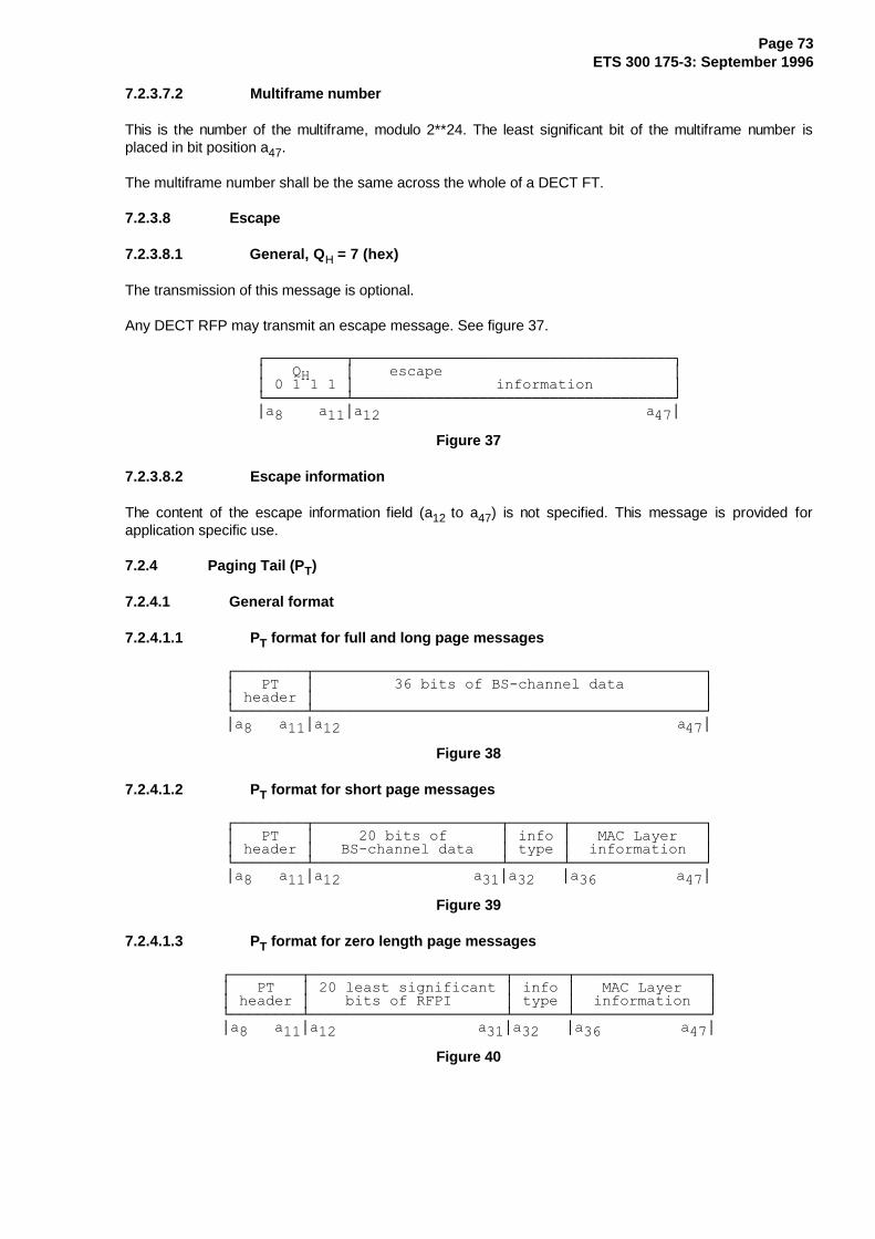
Page 73ETS 300 175-3: September 1996
7.2.3.7.2 Multiframe number
This is the number of the multiframe, modulo 2**24. The least significant bit of the multiframe number isplaced in bit position a47.
The multiframe number shall be the same across the whole of a DECT FT.
7.2.3.8 Escape
7.2.3.8.1 General, Q H = 7 (hex)
The transmission of this message is optional.
Any DECT RFP may transmit an escape message. See figure 37.
¸¶¶¶¶¶¶¶¶¶¾¶¶¶¶¶¶¶¶¶¶¶¶¶¶¶¶¶¶¶¶¶¶¶¶¶¶¶¶¶¶¶¶¶¶¶¶¹·���4+����·����HVFDSH��������������������������··���������·����������������LQIRUPDWLRQ���������·º¶¶¶¶¶¶¶¶¶¿¶¶¶¶¶¶¶¶¶¶¶¶¶¶¶¶¶¶¶¶¶¶¶¶¶¶¶¶¶¶¶¶¶¶¶¶»·D�����D��·D��������������������������������D��·
Figure 37
7.2.3.8.2 Escape information
The content of the escape information field (a12 to a47) is not specified. This message is provided forapplication specific use.
7.2.4 Paging Tail (P T)
7.2.4.1 General format
7.2.4.1.1 PT format for full and long page messages
¸¶¶¶¶¶¶¶¶¾¶¶¶¶¶¶¶¶¶¶¶¶¶¶¶¶¶¶¶¶¶¶¶¶¶¶¶¶¶¶¶¶¶¶¶¶¶¶¶¶¶¶¶¶¹·���37���·������������ELWV�RI�%6�FKDQQHO�GDWD���������··�KHDGHU�·��������������������������������������������·º¶¶¶¶¶¶¶¶¿¶¶¶¶¶¶¶¶¶¶¶¶¶¶¶¶¶¶¶¶¶¶¶¶¶¶¶¶¶¶¶¶¶¶¶¶¶¶¶¶¶¶¶¶»·D����D��·D����������������������������������������D��·
Figure 38
7.2.4.1.2 PT format for short page messages
¸¶¶¶¶¶¶¶¶¾¶¶¶¶¶¶¶¶¶¶¶¶¶¶¶¶¶¶¶¶¶¾¶¶¶¶¶¶¾¶¶¶¶¶¶¶¶¶¶¶¶¶¶¶¹·���37���·��������ELWV�RI������·�LQIR�·���0$&�/D\HU���··�KHDGHU�·���%6�FKDQQHO�GDWD���·�W\SH�·��LQIRUPDWLRQ��·º¶¶¶¶¶¶¶¶¿¶¶¶¶¶¶¶¶¶¶¶¶¶¶¶¶¶¶¶¶¶¿¶¶¶¶¶¶¿¶¶¶¶¶¶¶¶¶¶¶¶¶¶¶»·D����D��·D�����������������D��·D�����·D�����������D��·
Figure 39
7.2.4.1.3 PT format for zero length page messages
¸¶¶¶¶¶¶¶¶¾¶¶¶¶¶¶¶¶¶¶¶¶¶¶¶¶¶¶¶¶¶¶¾¶¶¶¶¶¶¾¶¶¶¶¶¶¶¶¶¶¶¶¶¶¶¹·���37���·����OHDVW�VLJQLILFDQW�·�LQIR�·���0$&�/D\HU���··�KHDGHU�·����ELWV�RI�5)3,������·�W\SH�·��LQIRUPDWLRQ��·º¶¶¶¶¶¶¶¶¿¶¶¶¶¶¶¶¶¶¶¶¶¶¶¶¶¶¶¶¶¶¶¿¶¶¶¶¶¶¿¶¶¶¶¶¶¶¶¶¶¶¶¶¶¶»·D����D��·D������������������D��·D�����·D�����������D��·
Figure 40

Page 74ETS 300 175-3: September 1996
7.2.4.2 PT header format
7.2.4.2.1 General format
¸¶¶¶¶¶¶¶¶¾¶¶¶¶¶¶¶¶¶¶¶¶¶¶¶¹·�H[WHQG�·�%6�6'8�OHQJWK�··��IODJ��·��LQGLFDWLRQ���·º¶¶¶¶¶¶¶¶¿¶¶¶¶¶¶¶¶¶¶¶¶¶¶¶»·���D����·D�����������D��·
Figure 41
7.2.4.2.2 Bit a 8 is the extend flag
a8 = 0: the next occurrence of a normal page shall be in a frame 0.
a8 = 1: another page message shall start in the next frame in this multiframe that is permitted to contain a PT type tail.
7.2.4.2.3 BS SDU length indication
Table 23
¸¶¶¶¶¶¶¶¶¶¶¶¾¶¶¶¶¶¶¶¶¶¶¶¶¶¶¶¶¶¶¶¶¶¶¶¶¶¶¶¶¶¶¶¶¶¶¶¶¶¹·�D��D���D��·�/HQJWK�LQGLFDWLRQ�������������������·¼¶¶¶¶¶¶¶¶¶¶¶À¶¶¶¶¶¶¶¶¶¶¶¶¶¶¶¶¶¶¶¶¶¶¶¶¶¶¶¶¶¶¶¶¶¶¶¶¶½·�����������·�]HUR�OHQJWK�SDJH��������������������··�����������·�VKRUW�SDJH��������������������������··�����������·�IXOO�SDJH���������������������������··�����������·�UHVHUYHG����������������������������··�����������·�QRW�WKH�ODVW����ELWV�RI�D�ORQJ�SDJH�··�����������·�WKH�ILUVW����ELWV�RI�D�ORQJ�SDJH����··�����������·�WKH�ODVW����ELWV�RI�D�ORQJ�SDJH�����··�����������·�DOO�RI�D�ORQJ�SDJH��ILUVW�DQG�ODVW��·º¶¶¶¶¶¶¶¶¶¶¶¿¶¶¶¶¶¶¶¶¶¶¶¶¶¶¶¶¶¶¶¶¶¶¶¶¶¶¶¶¶¶¶¶¶¶¶¶¶»
7.2.4.3 MAC layer information for PT
7.2.4.3.1 Information type
Table 24
¸¶¶¶¶¶¶¶¶¶¶¶¶¶¶¶¾¶¶¶¶¶¶¶¶¶¶¶¶¶¶¶¶¶¶¶¶¶¶¶¶¶¶¶¶¶¶¶¶¶¹·D���D���D���D��·�,QIRUPDWLRQ�W\SH����������������·¼¶¶¶¶¶¶¶¶¶¶¶¶¶¶¶À¶¶¶¶¶¶¶¶¶¶¶¶¶¶¶¶¶¶¶¶¶¶¶¶¶¶¶¶¶¶¶¶¶½·���������������·�ILOO�ELWV�����������������������··���������������·�EOLQG�IXOO�VORW�����������������··���������������·�RWKHU�EHDUHU��������������������··���������������·�UHFRPPHQGHG�RWKHU�EHDUHU��������··���������������·�JRRG�5)3�EHDUHU�����������������··���������������·�GXPP\�RU�&�/�EHDUHU�SRVLWLRQ����··���������������·�5)3�LGHQWLW\��������������������··���������������·�HVFDSH��������������������������··���������������·�GXPP\�RU�&�/�EHDUHU�PDUNHU������··���������������·�EHDUHU�KDQGRYHU�LQIRUPDWLRQ�����··���������������·�UIS�VWDWXV����������������������··���������������·�DFWLYH�FDUULHUV�����������������··���������������·�UHVHUYHG������������������������··���������������·�UHFRPPHQGHG�SRZHU�OHYHO���������··���������������·�`�������������������������������··�������WR������·��`�UHVHUYHG���������������������··���������������·�`�������������������������������·º¶¶¶¶¶¶¶¶¶¶¶¶¶¶¶¿¶¶¶¶¶¶¶¶¶¶¶¶¶¶¶¶¶¶¶¶¶¶¶¶¶¶¶¶¶¶¶¶¶»

Page 75ETS 300 175-3: September 1996
7.2.4.3.2 Fill bits
¸¶¶¶¶¶¶¶¶¶¾¶¶¶¶¶¶¶¶¶¶¶¶¶¶¶¶¶¶¶¹·���������·�������������������·º¶¶¶¶¶¶¶¶¶¿¶¶¶¶¶¶¶¶¶¶¶¶¶¶¶¶¶¶¶»·D�����D��·D���������������D��·
Figure 42
7.2.4.3.3 Blind full slot information
¸¶¶¶¾¶¶¶¾¶¶¶¾¶¶¶¾¶¶¶¾¶¶¶¾¶¶¶¾¶¶¶¾¶¶¶¾¶¶¶¾¶¶¶¾¶¶¶¹·D��·D��·D��·D��·D��·D��·D��·D��·D��·D��·D��·D��··���·���·���·���·���·���·���·���·���·���·���·���·º¶¶¶¿¶¶¶¿¶¶¶¿¶¶¶¿¶¶¶¿¶¶¶¿¶¶¶¿¶¶¶¿¶¶¶¿¶¶¶¿¶¶¶¿¶¶¶»·D�������������������������������������������D��·
Figure 43
For ax with 36 ≤ x ≤ 47:
if ax = 1: then full slot pair {(x-36),(x-24)} is not "blind", i.e. available;
else (ax = 0) full slot pair {(x-36),(x-24)} is "blind", i.e. not available.
NOTE: The blind slot information applies to the same slot number of all available carriers.
7.2.4.3.4 Bearer description
These codings are used to provide bearer information and consist of the following information types:
- other bearer;
- recommended other bearer;
- good RFP bearer; and
- dummy or connectionless bearer position.
The meaning of the messages are, however, different:
- "other bearer" means that this RFP has a bearer on the physical channel pair that is described in theremaining 12 bits;
- "recommended other bearer" means that this RFP has another bearer on the physical channel pairthat is described in the remaining 12 bits. This message shall not be sent unless the bearer that it issent on will be released in less than or equal to 4 multiframes;
NOTE 1: The bearer referred to in "other bearer" and "recommended other bearer" can meanany types of bearers indicated in subclause 5.5.2.
- "good RFP bearer" means that this RFP thinks that the physical channel pair described in theremaining 12 bits is a good bearer for the PT to use to set up a bearer with that RFP;
- "dummy or C/L bearer position" describes a dummy bearer position and/or marks the position of thebearer which is used for the downlink connectionless service.
NOTE 2: The "fixed part capabilities message" (see subclause 7.2.3.4) defines whether it isprohibited to setup a traffic bearer on this pair of physical channels.

Page 76ETS 300 175-3: September 1996
¸¶¶¶¶¶¶¶¶¶¾¶¶¶¶¶¾¶¶¶¶¶¶¶¶¶¶¶¶¶¹·���61����·�63��·�����&1������··���������·�����·�������������·º¶¶¶¶¶¶¶¶¶¿¶¶¶¶¶¿¶¶¶¶¶¶¶¶¶¶¶¶¶»·D�����D��·D����·D���������D��·
Figure 44
The coding of SP, SN, and CN are the same as in the "static system information" described insubclause 7.2.3.2. See figure 44 above.
7.2.4.3.5 RFP identity
¸¶¶¶¶¶¶¶¶¶¾¶¶¶¶¶¶¶¶¶¶¶¶¶¶¶¶¶¶¶¹·����OHDVW�VLJQLILFDQW�ELWV���··�����������RI�5)3,�����������·º¶¶¶¶¶¶¶¶¶¿¶¶¶¶¶¶¶¶¶¶¶¶¶¶¶¶¶¶¶»·D�������������������������D��·
Figure 45
7.2.4.3.6 Escape
Any DECT RFP may transmit an escape message.
The content of the escape information field (a36 to a47) is not specified. This message is provided forproprietary.
7.2.4.3.7 Dummy or connectionless downlink bearer marker
¸¶¶¶¶¶¶¶¶¶¾¶¶¶¶¶¶¶¶¶¶¶¶¶¶¶¶¶¶¶¹·���������·�������������������··���������·�������������������·º¶¶¶¶¶¶¶¶¶¿¶¶¶¶¶¶¶¶¶¶¶¶¶¶¶¶¶¶¶»·D�����D��·D���������������D��·
Figure 46
This message shall only be transmitted on a dummy bearer or on a connectionless downlink bearer.
7.2.4.3.8 Bearer handover information
¸¶¶¶¶¶¶¶¶¶¾¶¶¶¶¶¶¶¶¶¶¶¶¶¶¶¶¶¶¶¹·��LQIR���·��SDUDPHWHU��������··��W\SH���·�������������������·º¶¶¶¶¶¶¶¶¶¿¶¶¶¶¶¶¶¶¶¶¶¶¶¶¶¶¶¶¶»·D�����D��·D���������������D��·
Figure 47
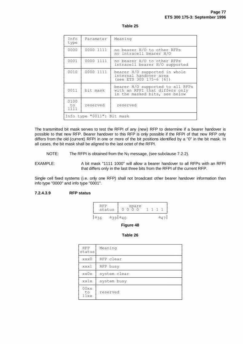
Page 77ETS 300 175-3: September 1996
Table 25
¸¶¶¶¶¶¶¾¶¶¶¶¶¶¶¶¶¶¶¾¶¶¶¶¶¶¶¶¶¶¶¶¶¶¶¶¶¶¶¶¶¶¶¶¶¶¶¶¶¶¶¶¶¶¹·�,QIR�·�3DUDPHWHU�·�0HDQLQJ��������������������������··�W\SH�·�����������·����������������������������������·¼¶¶¶¶¶¶À¶¶¶¶¶¶¶¶¶¶¶À¶¶¶¶¶¶¶¶¶¶¶¶¶¶¶¶¶¶¶¶¶¶¶¶¶¶¶¶¶¶¶¶¶¶½·������·�����������·�QR�EHDUHU�+�2�WR�RWKHU�5)3V������··������·�����������·�QR�LQWUDFHOO�EHDUHU�+�2����������·¼¶¶¶¶¶¶À¶¶¶¶¶¶¶¶¶¶¶À¶¶¶¶¶¶¶¶¶¶¶¶¶¶¶¶¶¶¶¶¶¶¶¶¶¶¶¶¶¶¶¶¶¶½·������·�����������·�QR�EHDUHU�+�2�WR�RWKHU�5)3V������··������·�����������·�LQWUDFHOO�EHDUHU�+�2�VXSSRUWHG���·¼¶¶¶¶¶¶À¶¶¶¶¶¶¶¶¶¶¶À¶¶¶¶¶¶¶¶¶¶¶¶¶¶¶¶¶¶¶¶¶¶¶¶¶¶¶¶¶¶¶¶¶¶½·������·�����������·�EHDUHU�+�2�VXSSRUWHG�LQ�ZKROH����··������·�����������·�LQWHUQDO�KDQGRYHU�DUHD�����������··������·�����������·��VHH�(76�����������>�@�����������·¼¶¶¶¶¶¶À¶¶¶¶¶¶¶¶¶¶¶À¶¶¶¶¶¶¶¶¶¶¶¶¶¶¶¶¶¶¶¶¶¶¶¶¶¶¶¶¶¶¶¶¶¶½·������·�����������·�EHDUHU�+�2�VXSSRUWHG�WR�DOO�5)3V�··������·�ELW�PDVN��·�ZLWK�DQ�5)3,�WKDW�GLIIHUV�RQO\���··������·�����������·�LQ�WKH�PDVNHG�ELWV��VHH�EHORZ����·¼¶¶¶¶¶¶À¶¶¶¶¶¶¶¶¶¶¶À¶¶¶¶¶¶¶¶¶¶¶¶¶¶¶¶¶¶¶¶¶¶¶¶¶¶¶¶¶¶¶¶¶¶½·������·�����������·����������������������������������··��WR��·�UHVHUYHG��·��UHVHUYHG������������������������··������·�����������·����������������������������������·¼¶¶¶¶¶¶¿¶¶¶¶¶¶¶¶¶¶¶¿¶¶¶¶¶¶¶¶¶¶¶¶¶¶¶¶¶¶¶¶¶¶¶¶¶¶¶¶¶¶¶¶¶¶½·,QIR�W\SH���������%LW�PDVN���������������������������·º¶¶¶¶¶¶¶¶¶¶¶¶¶¶¶¶¶¶¶¶¶¶¶¶¶¶¶¶¶¶¶¶¶¶¶¶¶¶¶¶¶¶¶¶¶¶¶¶¶¶¶¶¶»
The transmitted bit mask serves to test the RFPI of any (new) RFP to determine if a bearer handover ispossible to that new RFP. Bearer handover to this RFP is only possible if the RFPI of that new RFP onlydiffers from the old (current) RFPI in one or more of the bit positions identified by a "0" in the bit mask. Inall cases, the bit mask shall be aligned to the last octet of the RFPI.
NOTE: The RFPI is obtained from the NT message, (see subclause 7.2.2).
EXAMPLE: A bit mask "1111 1000" will allow a bearer handover to all RFPs with an RFPIthat differs only in the last three bits from the RFPI of the current RFP.
Single cell fixed systems (i.e. only one RFP) shall not broadcast other bearer handover information thaninfo type "0000" and info type "0001".
7.2.4.3.9 RFP status
¸¶¶¶¶¶¶¶¶¶¾¶¶¶¶¶¶¶¶¶¶¶¶¶¶¶¶¶¶¶¹·��5)3����·����VSDUH����������··��VWDWXV�·�������������������·º¶¶¶¶¶¶¶¶¶¿¶¶¶¶¶¶¶¶¶¶¶¶¶¶¶¶¶¶¶»·D�����D��·D���������������D��·
Figure 48
Table 26
¸¶¶¶¶¶¶¾¶¶¶¶¶¶¶¶¶¶¶¶¶¶¶¶¶¶¶¶¶¶¶¶¶¶¶¶¶¶¶¶¶¶¹·�5)3��·�0HDQLQJ��������������������������··VWDWXV·����������������������������������·¼¶¶¶¶¶¶À¶¶¶¶¶¶¶¶¶¶¶¶¶¶¶¶¶¶¶¶¶¶¶¶¶¶¶¶¶¶¶¶¶¶½·�[[[��·�5)3�FOHDU������������������������·¼¶¶¶¶¶¶À¶¶¶¶¶¶¶¶¶¶¶¶¶¶¶¶¶¶¶¶¶¶¶¶¶¶¶¶¶¶¶¶¶¶½·�[[[��·�5)3�EXV\�������������������������·¼¶¶¶¶¶¶À¶¶¶¶¶¶¶¶¶¶¶¶¶¶¶¶¶¶¶¶¶¶¶¶¶¶¶¶¶¶¶¶¶¶½·�[[�[�·�V\VWHP�FOHDU���������������������·¼¶¶¶¶¶¶À¶¶¶¶¶¶¶¶¶¶¶¶¶¶¶¶¶¶¶¶¶¶¶¶¶¶¶¶¶¶¶¶¶¶½·�[[�[�·�V\VWHP�EXV\����������������������·¼¶¶¶¶¶¶À¶¶¶¶¶¶¶¶¶¶¶¶¶¶¶¶¶¶¶¶¶¶¶¶¶¶¶¶¶¶¶¶¶¶½·���[[�·����������������������������������··��WR��·�UHVHUYHG�������������������������··���[[�·����������������������������������·º¶¶¶¶¶¶¿¶¶¶¶¶¶¶¶¶¶¶¶¶¶¶¶¶¶¶¶¶¶¶¶¶¶¶¶¶¶¶¶¶¶»

Page 78ETS 300 175-3: September 1996
7.2.4.3.10 Active carriers
¸¶¶¶¶¶¶¶¶¶¶¶¶¶¶¶¶¶¶¶¶¶¶¶¶¶¶¶¾¶¶¶¶¶¶¶¶¶¹·�����DFWLYH�FDUULHUV�������·��VSDUH��··���������������������������·���������·º¶¶¶¶¶¶¶¶¶¶¶¶¶¶¶¶¶¶¶¶¶¶¶¶¶¶¶¿¶¶¶¶¶¶¶¶¶»·D�����������������������D��·D�����D��·
Figure 49
For ax, with 36 ≤ x ≤ 45:
if ax = 0 then RFP is not transmitting on carrier (x-36);
if ax = 1 then RFP is active transmitting on carrier (x-36);
Bits a46 and a47 are spare.
7.2.4.3.11 Recommended PP power level
¸¶¶¶¶¶¶¶¶¶¶¶¶¶¶¶¶¶¶¶¶¶¶¶¶¶¶¶¾¶¶¶¶¶¶¶¶¶¶¶¶¶¶¶¾¶¶¶¶¶¶¶¶¶¶¶¶¶¶¶¹·����UHVHUYHG�IRU�IXWXUH����·�IRU�FDUULHUV��·�IRU�FDUULHUV��··�������GHYHORSPHQW���������·����F����������·�����≤�F�≤�����·º¶¶¶¶¶¶¶¶¶¶¶¶¶¶¶¶¶¶¶¶¶¶¶¶¶¶¶¿¶¶¶¶¶¶¶¶¶¶¶¶¶¶¶¿¶¶¶¶¶¶¶¶¶¶¶¶¶¶¶»·D�����������������������D��·D�����������D��·������������D��·
Figure 50
The coding of bit a47 is shown in the following table:
Table 27
¸¶¶¶¶¶¶¶¶¶¶¾¶¶¶¶¶¶¶¶¶¶¶¶¶¶¶¶¶¶¶¶¶¶¶¶¶¶¶¶¶¶¶¶¶¶¶¶¹·����D�����·�33�3RZHU�/HYHO���������������������·¼¶¶¶¶¶¶¶¶¶¶À¶¶¶¶¶¶¶¶¶¶¶¶¶¶¶¶¶¶¶¶¶¶¶¶¶¶¶¶¶¶¶¶¶¶¶¶½·����������·�OHYHO������������������������������··����������·�OHYHO������������������������������·º¶¶¶¶¶¶¶¶¶¶¿¶¶¶¶¶¶¶¶¶¶¶¶¶¶¶¶¶¶¶¶¶¶¶¶¶¶¶¶¶¶¶¶¶¶¶¶»
The coding of bits a45 to a46 is shown in the following table:
Table 28
¸¶¶¶¶¶¶¶¶¶¶¶¶¶¶¾¶¶¶¶¶¶¶¶¶¶¶¶¶¶¶¶¶¶¶¶¶¶¶¶¶¶¶¶¶¶¶¶¶¶¶¶¹·��D�����D�����·33�3RZHU�/HYHO����������������������·¼¶¶¶¶¶¶¶¶¶¶¶¶¶¶À¶¶¶¶¶¶¶¶¶¶¶¶¶¶¶¶¶¶¶¶¶¶¶¶¶¶¶¶¶¶¶¶¶¶¶¶½·��������������·�OHYHO������������������������������··��������������·�OHYHO������������������������������··��������������·�OHYHO������������������������������··��������������·�OHYHO������������������������������·º¶¶¶¶¶¶¶¶¶¶¶¶¶¶¿¶¶¶¶¶¶¶¶¶¶¶¶¶¶¶¶¶¶¶¶¶¶¶¶¶¶¶¶¶¶¶¶¶¶¶¶»
The PP, if it is capable of doing so, and unless instructed otherwise, at link initiation shall operate at apower level to correspond to that recommended. No other power level than 250 mW is currently defined inETS 300 175-2 [2].

Page 79ETS 300 175-3: September 1996
7.2.5 MAC control (M T)
7.2.5.1 General format and contents
Two different combinations of TA bits are used to indicate the presence of MAC layer control information inthe tail. The "first PT transmission" code is used only in the first transmission from a PT. This is intended toaid RFPs in busy systems to identify bearer set up requests amongst a background of ongoingconnections.
¸¶¶¶¶¶¶¾¶¶¶¶¶¶¾¶¶¶¶¶¶¶¶¾¶¶¶¶¶¶¶¶¾¶¶¶¶¶¶¶¶¾¶¶¶¶¶¶¶¶¹·��07��·�FRP��·�����������������������������������··KHDGHU·�PDQG�·����PRUH�KHDGHUV�RU�LQIRUPDWLRQ����··������·������·�����������������������������������·º¶¶¶¶¶¶¿¶¶¶¶¶¶¿¶¶¶¶¶¶¶¶¿¶¶¶¶¶¶¶¶¿¶¶¶¶¶¶¶¶¿¶¶¶¶¶¶¶¶»·D�����·D�����·D�������������������������������D��·
Figure 51
MT messages (see figure 51 above) are sent as 40 bit packets in the tail of the A-field. The first 4 bitheader provides a coarse division of messages and for most message types a second header, completingthe first octet, provides a finer division of the messages.
Table 29
¸¶¶¶¶¶¶¶¶¾¶¶¶¶¶¶¶¶¶¶¶¶¶¶¶¶¶¶¶¶¶¶¶¶¶¶¶¶¶¶¶¶¶¶¶¶¶¶¶¶¶¶¶¶¶¶¹·���07���·��0HVVDJH�W\SH��������������������������������··�KHDGHU�·����������������������������������������������·¼¶¶¶¶¶¶¶¶À¶¶¶¶¶¶¶¶¶¶¶¶¶¶¶¶¶¶¶¶¶¶¶¶¶¶¶¶¶¶¶¶¶¶¶¶¶¶¶¶¶¶¶¶¶¶½·��������·�EDVLF�FRQQHFWLRQ�FRQWURO���������������������··��������·�DGYDQFHG�FRQQHFWLRQ�FRQWURO������������������··��������·�0$&�OD\HU�WHVW�PHVVDJHV����������������������··��������·�TXDOLW\�FRQWURO������������������������������··��������·�EURDGFDVW�DQG�FRQQHFWLRQOHVV�VHUYLFHV��������··��������·�HQFU\SWLRQ�FRQWURO���������������������������··��������·�7DLO�IRU�XVH�ZLWK�WKH�ILUVW�WUDQVPLVVLRQ�RI��··��������·�D�%�ILHOG��EHDUHU�UHTXHVW��PHVVDJH�ZKHQ�QRW��··��������·�DOVR�VHQGLQJ�DQ�$�ILHOG��EHDUHU�UHTXHVW������··��������·�HVFDSH���������������������������������������··��������·�7$5,�PHVVDJH���������������������������������··��������·�5(3�FRQQHFWLRQ�FRQWURO�����������������������··��������·�`��������������������������������������������··���WR���·��`�UHVHUYHG����������������������������������··��������·�`��������������������������������������������·º¶¶¶¶¶¶¶¶¿¶¶¶¶¶¶¶¶¶¶¶¶¶¶¶¶¶¶¶¶¶¶¶¶¶¶¶¶¶¶¶¶¶¶¶¶¶¶¶¶¶¶¶¶¶¶»
7.2.5.2 Basic connection control
7.2.5.2.1 General
The basic connection control messages shall only be used by PPs and RFPs that are attempting toestablish a single duplex bearer voice connection with a B-field of 324 bits.
7.2.5.2.2 Format for most messages
¸¶¶¶¶¾¶¶¶¶¶¶¾¶¶¶¶¶¶¶¶¶¶¶¶¾¶¶¶¶¶¶¶¶¶¶¶¶¶¶¶¶¶¶¶¶¹·����·�FRP��·������������·��������������������··����·�PDQG�·����)0,'����·��������30,'��������··����·������·������������·��������������������·º¶¶¶¶¿¶¶¶¶¶¶¿¶¶¶¶¶¶¶¶¶¶¶¶¿¶¶¶¶¶¶¶¶¶¶¶¶¶¶¶¶¶¶¶¶»·D���·D�����·D�����������·D�������������������··�D��·���D��·���������D��·�����������������D��·
NOTE: For definitions of FMID, PMID, see subclause 11.7.
Figure 52

Page 80ETS 300 175-3: September 1996
Table 30
¸¶¶¶¶¶¶¶¶¾¶¶¶¶¶¶¶¶¶¶¶¶¶¶¶¶¶¶¶¶¶¶¶¶¶¶¶¶¶¶¶¶¶¶¶¶¶¶¶¶¶¶¶¶¶¶¶¶¶¶¶¶¶¹·&RPPDQG�·���%DVLF�FRQQHFWLRQ�FRQWURO�PHVVDJHV�����������������·¼¶¶¶¶¶¶¶¶À¶¶¶¶¶¶¶¶¶¶¶¶¶¶¶¶¶¶¶¶¶¶¶¶¶¶¶¶¶¶¶¶¶¶¶¶¶¶¶¶¶¶¶¶¶¶¶¶¶¶¶¶¶½·��������·�DFFHVVBUHTXHVW����������������������������������� �··��������·�EHDUHUBKDQGRYHUBUHTXHVW�������������������������� �··��������·�FRQQHFWLRQBKDQGRYHUBUHTXHVW���������������������� �··��������·�XQFRQILUPHGBDFFHVVBUHTXHVW����������������������� �··��������·�EHDUHUBFRQILUP��������������������������������������··��������·�ZDLW��IRUPDW�VHH�VXEFODXVH��������������������������··��������·�`���������������������������������������������������··���WR���·��`�UHVHUYHG�����������������������������������������··��������·�`���������������������������������������������������··��������·�UHOHDVH���������������������������������������������·¼¶¶¶¶¶¶¶¶¿¶¶¶¶¶¶¶¶¶¶¶¶¶¶¶¶¶¶¶¶¶¶¶¶¶¶¶¶¶¶¶¶¶¶¶¶¶¶¶¶¶¶¶¶¶¶¶¶¶¶¶¶¶½·� �LQGLFDWHV�PHVVDJHV�WKDW�XVH�WKH��ILUVW�37�WUDQVPLVVLRQ����··����FRGH��7KH�RWKHU�PHVVDJHV�XVH�WKH�QRUPDO�07�FRGH�����������·º¶¶¶¶¶¶¶¶¶¶¶¶¶¶¶¶¶¶¶¶¶¶¶¶¶¶¶¶¶¶¶¶¶¶¶¶¶¶¶¶¶¶¶¶¶¶¶¶¶¶¶¶¶¶¶¶¶¶¶¶¶¶»
This release message shall only refer to the bearer that it is transmitted on.
NOTE 1: An RFP that receives an UNCONFIRMED_ACCESS_REQUEST message does notreturn a BEARER_CONFIRM. It may listen to following frames to receive MACattributes messages or data.
NOTE 2: The use of the UNCONFIRMED_ACCESS_REQUEST message is intended here forachieving handover by changing base stations but remaining on the same physicalchannel. The use of this message in basic cases is still uncertain.
NOTE 3: Fast bearer set up requests are not allowed in basic A-field setups.
The FT may use the messages indicated with ** without the "first PT transmission" code.
7.2.5.2.3 WAIT
¸¶¶¶¶¾¶¶¶¶¾¶¶¶¶¶¶¶¶¾¶¶¶¶¾¶¶¶¶¶¾¶¶¶¶¶¶¶¶¶¾¶¶¶¶¶¶¶¶¶¶¹·����·����·�������������·����������30,'�RU���������··����·����·������)0,'���·����������VSDUH�����������··����·����·�������������·��������������������������·º¶¶¶¶¿¶¶¶¶¿¶¶¶¶¶¶¶¶¿¶¶¶¶¿¶¶¶¶¶¿¶¶¶¶¶¶¶¶¶¿¶¶¶¶¶¶¶¶¶¶»·D���·D���·D������������·D�������������������������··�D��·�D��·����������D��·�����������������������D��·
NOTE: The procedure does not make reference to the values of a16 to a47. It is not intended that thecontents of this field be included in any mandatory tests.
Figure 53

Page 81ETS 300 175-3: September 1996
7.2.5.3 Advanced connection control
7.2.5.3.1 General
Table 31
¸¶¶¶¶¶¶¶¶¾¶¶¶¶¶¶¶¶¶¶¶¶¶¶¶¶¶¶¶¶¶¶¶¶¶¶¶¶¶¶¶¶¶¶¶¶¶¶¶¶¶¶¶¶¶¶¶¶¶¹·&RPPDQG�·����$GYDQFHG�FRQQHFWLRQ�FRQWURO������������������··��������·�������������PHVVDJHV����������������������������·¼¶¶¶¶¶¶¶¶À¶¶¶¶¶¶¶¶¶¶¶¶¶¶¶¶¶¶¶¶¶¶¶¶¶¶¶¶¶¶¶¶¶¶¶¶¶¶¶¶¶¶¶¶¶¶¶¶¶½·��������·�$&&(66B5(48(67������������������������������� �··��������·�EHDUHUBKDQGRYHUBUHTXHVW���������������������� �··��������·�FRQQHFWLRQBKDQGRYHUBUHTXHVW������������������ �··��������·�XQFRQILUPHGBDFFHVVBUHTXHVW������������������� �··��������·�EHDUHUBFRQILUP����������������������������������··��������·�ZDLW��FRQWDLQV�)0,'�����������������������������··��������·�DWWULEXWHVB7�UHTXHVW����������������������������··��������·�DWWULEXWHVB7�FRQILUP����������������������������··��������·�EDQGZLGWKB7�UHTXHVW�����������������������������··��������·�EDQGZLGWKB7�FRQILUP�����������������������������··��������·�FKDQQHOBOLVW������������������������������������··��������·�XQFRQILUPHGBGXPP\���������������������������� �··��������·�XQFRQILUPHGBKDQGRYHU������������������������� �··��������·�UHVHUYHG����������������������������������������··��������·�UHVHUYHG����������������������������������������··��������·�UHOHDVH�����������������������������������������·¼¶¶¶¶¶¶¶¶¿¶¶¶¶¶¶¶¶¶¶¶¶¶¶¶¶¶¶¶¶¶¶¶¶¶¶¶¶¶¶¶¶¶¶¶¶¶¶¶¶¶¶¶¶¶¶¶¶¶½·� �LQGLFDWHV�PHVVDJHV�WKDW��LI�WUDQVPLWWHG�E\�D�37��XVH��··����WKH�ILUVW�37�WUDQVPLVVLRQ��FRGH�����������������������·º¶¶¶¶¶¶¶¶¶¶¶¶¶¶¶¶¶¶¶¶¶¶¶¶¶¶¶¶¶¶¶¶¶¶¶¶¶¶¶¶¶¶¶¶¶¶¶¶¶¶¶¶¶¶¶¶¶¶»
These messages allow a complicated connection to be established using MT messages. The connectionset up time is expected to be much longer than if MAC control messages are sent in the B-field.
The FT may use the messages indicated with ** without the "first PT transmission" code.
7.2.5.3.2 ACCESS_REQUEST
¸¶¶¶¶¾¶¶¶¶¾¶¶¶¶¶¶¶¶¾¶¶¶¶¾¶¶¶¶¾¶¶¶¶¶¶¶¶¾¶¶¶¶¶¶¶¶¹·����·����·�������������·����������������������··����·����·�����)0,'����·��������30,'����������··����·����·�������������·����������������������·º¶¶¶¶¿¶¶¶¶¿¶¶¶¶¶¶¶¶¿¶¶¶¶¿¶¶¶¶¿¶¶¶¶¶¶¶¶¿¶¶¶¶¶¶¶¶»·D���·D���·D������������·D���������������������··�D��·�D��·����������D��·�������������������D��·
Figure 54
7.2.5.3.3 BEARER_HANDOVER_REQUEST
¸¶¶¶¶¾¶¶¶¶¾¶¶¶¶¶¶¶¶¾¶¶¶¶¾¶¶¶¶¾¶¶¶¶¶¶¶¶¾¶¶¶¶¶¶¶¶¹·����·����·�������������·����������������������··����·����·�����)0,'����·��������30,'����������··����·����·�������������·����������������������·º¶¶¶¶¿¶¶¶¶¿¶¶¶¶¶¶¶¶¿¶¶¶¶¿¶¶¶¶¿¶¶¶¶¶¶¶¶¿¶¶¶¶¶¶¶¶»·D���·D���·D������������·D���������������������··�D��·�D��·����������D��·�������������������D��·
Figure 55
7.2.5.3.4 CONNECTION_HANDOVER_REQUEST
¸¶¶¶¶¾¶¶¶¶¾¶¶¶¶¶¶¶¶¾¶¶¶¶¾¶¶¶¶¾¶¶¶¶¶¶¶¶¾¶¶¶¶¶¶¶¶¹·����·����·�������������·����������������������··����·����·�����)0,'����·��������30,'����������··����·����·�������������·����������������������·º¶¶¶¶¿¶¶¶¶¿¶¶¶¶¶¶¶¶¿¶¶¶¶¿¶¶¶¶¿¶¶¶¶¶¶¶¶¿¶¶¶¶¶¶¶¶»·D���·D���·D������������·D���������������������··�D��·�D��·����������D��·�������������������D��·
Figure 56

Page 82ETS 300 175-3: September 1996
7.2.5.3.5 UNCONFIRMED_ACCESS_REQUEST
¸¶¶¶¶¾¶¶¶¶¾¶¶¶¶¶¶¶¶¾¶¶¶¶¾¶¶¶¶¾¶¶¶¶¶¶¶¶¾¶¶¶¶¶¶¶¶¹·����·����·�������������·����������������������··����·����·�����)0,'����·��������30,'����������··����·����·�������������·����������������������·º¶¶¶¶¿¶¶¶¶¿¶¶¶¶¶¶¶¶¿¶¶¶¶¿¶¶¶¶¿¶¶¶¶¶¶¶¶¿¶¶¶¶¶¶¶¶»·D���·D���·D������������·D���������������������··D���·D���·����������D��·�������������������D��·
NOTE: An RFP that receives an UNCONFIRMED_ACCESS_REQUEST message does not return aconfirm. It may listen to following frames to receive MAC attributes messages or data.
Figure 57
7.2.5.3.6 BEARER_CONFIRM
¸¶¶¶¶¾¶¶¶¶¾¶¶¶¶¶¶¶¶¾¶¶¶¶¾¶¶¶¶¾¶¶¶¶¶¶¶¶¾¶¶¶¶¶¶¶¶¹·����·����·�������������·����������������������··����·����·�����)0,'����·��������30,'����������··����·����·�������������·����������������������·º¶¶¶¶¿¶¶¶¶¿¶¶¶¶¶¶¶¶¿¶¶¶¶¿¶¶¶¶¿¶¶¶¶¶¶¶¶¿¶¶¶¶¶¶¶¶»·D���·D���·D������������·D���������������������··�D��·�D��·����������D��·�������������������D��·
Figure 58
7.2.5.3.7 WAIT
¸¶¶¶¶¾¶¶¶¶¾¶¶¶¶¶¶¶¶¾¶¶¶¶¾¶¶¶¶¶¾¶¶¶¶¶¶¶¶¶¾¶¶¶¶¶¶¶¶¶¶¹·����·����·�������������·����������30,'�RU���������··����·����·�����)0,'����·�����������VSDUH����������··����·����·�������������·��������������������������·º¶¶¶¶¿¶¶¶¶¿¶¶¶¶¶¶¶¶¿¶¶¶¶¿¶¶¶¶¶¿¶¶¶¶¶¶¶¶¶¿¶¶¶¶¶¶¶¶¶¶»·D���·D���·D������������·D�������������������������··�D��·�D��·����������D��·�����������������������D��·
NOTE: The procedure does not make reference to the values of a16 to a47. It is not intended that thecontents of this field be included in any mandatory tests.
Figure 59
7.2.5.3.8 ATTRIBUTES_T.{Req;Cfm}
¶¶¶¾¶¶¶¾¶¾¶¶¶¶¾¶¶¶¶¾¶¶¶¶¶¾¶¶¶¶¶¾¶¶¶¶¶¾¶¶¶¶¾¶¾¶¶¶¾¶¶¶¶¶¶¶¶¶¹·����·���·5·����·����·�XS��·�VHU�·�PD[�·VORW·&·���·���������··����·���·�·(&1�·/%1�·GRZQ�·W\SH�·OLIH�·W\SH·)·���·���������··����·���·&·����·����·VP�VV·�����·�����·����·�·VSU·��VSDUH��·º¶¶¶¶¿¶¶¶¿¶¿¶¶¶¶¿¶¶¶¶¿¶¶¶¶¶¿¶¶¶¶¶¿¶¶¶¶¶¿¶¶¶¶¿¶¿¶¶¶¿¶¶¶¶¶¶¶¶¶»·D���·D����·D���·D���·D����·D����·D����·D���·D����·D��������··�D��·��D��·�D��·�D��·��D��·��D��·��D��·�D��·��D��·������D��·
Figure 60
Table 32
¸¶¶¶¶¶¾¶¶¶¶¶¶¶¶¶¹·�5�&�·�0HDQLQJ�·¼¶¶¶¶¶À¶¶¶¶¶¶¶¶¶½·�����·�UHTXHVW�··�����·�FRQILUP�·º¶¶¶¶¶¿¶¶¶¶¶¶¶¶¶»
ECN:Exchanged Connection Number.
LBN: Logical Bearer Number.
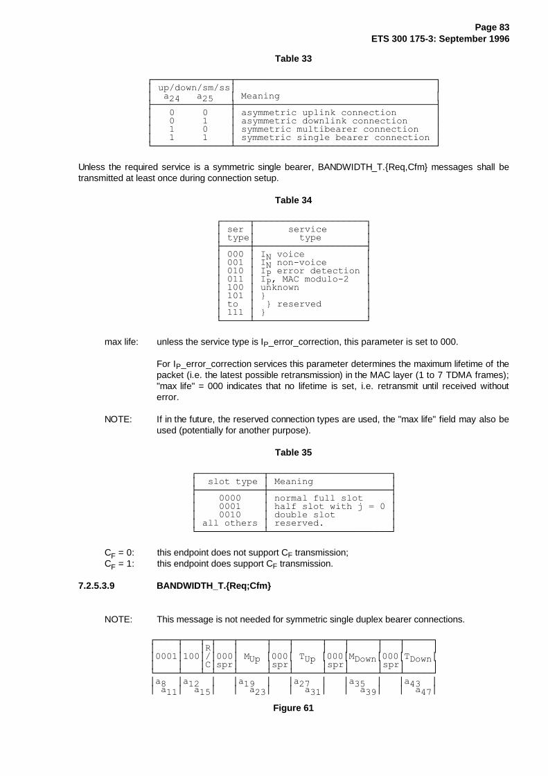
Page 83ETS 300 175-3: September 1996
Table 33
¸¶¶¶¶¶¶¶¶¶¶¶¶¶¶¾¶¶¶¶¶¶¶¶¶¶¶¶¶¶¶¶¶¶¶¶¶¶¶¶¶¶¶¶¶¶¶¶¶¶¶¶¹·�XS�GRZQ�VP�VV·������������������������������������··��D�����D�����·�0HDQLQJ����������������������������·¼¶¶¶¶¶¶¶¶¶¶¶¶¶¶À¶¶¶¶¶¶¶¶¶¶¶¶¶¶¶¶¶¶¶¶¶¶¶¶¶¶¶¶¶¶¶¶¶¶¶¶½·��������������·�DV\PPHWULF�XSOLQN�FRQQHFWLRQ�������··��������������·�DV\PPHWULF�GRZQOLQN�FRQQHFWLRQ�����··��������������·�V\PPHWULF�PXOWLEHDUHU�FRQQHFWLRQ���··��������������·�V\PPHWULF�VLQJOH�EHDUHU�FRQQHFWLRQ�·º¶¶¶¶¶¶¶¶¶¶¶¶¶¶¿¶¶¶¶¶¶¶¶¶¶¶¶¶¶¶¶¶¶¶¶¶¶¶¶¶¶¶¶¶¶¶¶¶¶¶¶»
Unless the required service is a symmetric single bearer, BANDWIDTH_T.{Req,Cfm} messages shall betransmitted at least once during connection setup.
Table 34
¸¶¶¶¶¶¾¶¶¶¶¶¶¶¶¶¶¶¶¶¶¶¶¶¶¶¶¹·�VHU�·������VHUYLFH�������··�W\SH·��������W\SH��������·¼¶¶¶¶¶À¶¶¶¶¶¶¶¶¶¶¶¶¶¶¶¶¶¶¶¶½·�����·�,1�YRLFH�����������··�����·�,1�QRQ�YRLFH�������··�����·�,3�HUURU�GHWHFWLRQ�··�����·�,3��0$&�PRGXOR�����··�����·�XQNQRZQ������������··�����·�`������������������··�WR��·��`�UHVHUYHG��������··�����·�`������������������·º¶¶¶¶¶¿¶¶¶¶¶¶¶¶¶¶¶¶¶¶¶¶¶¶¶¶»
max life: unless the service type is IP_error_correction, this parameter is set to 000.
For IP_error_correction services this parameter determines the maximum lifetime of thepacket (i.e. the latest possible retransmission) in the MAC layer (1 to 7 TDMA frames);"max life" = 000 indicates that no lifetime is set, i.e. retransmit until received withouterror.
NOTE: If in the future, the reserved connection types are used, the "max life" field may also beused (potentially for another purpose).
Table 35
¸¶¶¶¶¶¶¶¶¶¶¶¶¾¶¶¶¶¶¶¶¶¶¶¶¶¶¶¶¶¶¶¶¶¶¶¹·��VORW�W\SH�·�0HDQLQJ��������������·¼¶¶¶¶¶¶¶¶¶¶¶¶À¶¶¶¶¶¶¶¶¶¶¶¶¶¶¶¶¶¶¶¶¶¶½·������������·�QRUPDO�IXOO�VORW�����··������������·�KDOI�VORW�ZLWK�M� ���··������������·�GRXEOH�VORW����������··�DOO�RWKHUV�·�UHVHUYHG�������������·º¶¶¶¶¶¶¶¶¶¶¶¶¿¶¶¶¶¶¶¶¶¶¶¶¶¶¶¶¶¶¶¶¶¶¶»
CF = 0: this endpoint does not support CF transmission;CF = 1: this endpoint does support CF transmission.
7.2.5.3.9 BANDWIDTH_T.{Req;Cfm}
NOTE: This message is not needed for symmetric single duplex bearer connections.
¸¶¶¶¶¾¶¶¶¾¶¾¶¶¶¾¶¶¶¶¶¾¶¶¶¾¶¶¶¶¶¾¶¶¶¾¶¶¶¶¶¾¶¶¶¾¶¶¶¶¶¹·����·���·5·���·�����·���·�����·���·�����·���·�����··����·���·�·���·�08S�·���·�78S�·���·0'RZQ·���·7'RZQ··����·���·&·VSU·�����·VSU·�����·VSU·�����·VSU·�����·º¶¶¶¶¿¶¶¶¿¶¿¶¶¶¿¶¶¶¶¶¿¶¶¶¿¶¶¶¶¶¿¶¶¶¿¶¶¶¶¶¿¶¶¶¿¶¶¶¶¶»·D���·D����·���·D����·���·D����·���·D����·���·D����··�D��·��D��·���·��D��·���·��D��·���·��D��·���·��D��·
Figure 61
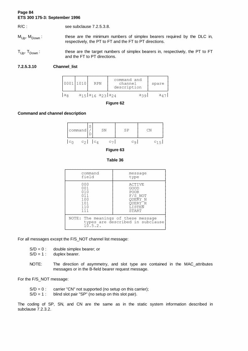
Page 84ETS 300 175-3: September 1996
R/C : see subclause 7.2.5.3.8.
MUp, MDown : these are the minimum numbers of simplex bearers required by the DLC in,respectively, the PT to FT and the FT to PT directions.
TUp, TDown : these are the target numbers of simplex bearers in, respectively, the PT to FTand the FT to PT directions.
7.2.5.3.10 Channel_list
¸¶¶¶¶¾¶¶¶¶¾¶¶¶¶¶¶¶¾¶¶¶¶¶¶¶¶¶¶¶¶¶¶¶¾¶¶¶¶¶¶¶¹·����·����·�������·��FRPPDQG�DQG��·�������··����·����·��531��·����FKDQQHO����·�VSDUH�··����·����·�������·��GHVFULSWLRQ��·�������·º¶¶¶¶¿¶¶¶¶¿¶¶¶¶¶¶¶¿¶¶¶¶¶¶¶¶¶¶¶¶¶¶¶¿¶¶¶¶¶¶¶»·D�����D��·D���D��·D�����������D��·����D��·
Figure 62
Command and channel description
¸¶¶¶¶¶¶¶¾¶¾¶¶¶¶¶¶¶¶¾¶¶¶¶¶¶¶¶¾¶¶¶¶¶¶¶¶¶¹·�������·6·��������·��������·���������··FRPPDQG·�·���61���·���63���·���&1����··�������·'·��������·��������·���������·º¶¶¶¶¶¶¶¿¶¿¶¶¶¶¶¶¶¶¿¶¶¶¶¶¶¶¶¿¶¶¶¶¶¶¶¶¶»·F����F�·�·F�����F�·������F�·������F��·
Figure 63
Table 36
¸¶¶¶¶¶¶¶¶¶¶¶¶¶¶¶¶¶¶¾¶¶¶¶¶¶¶¶¶¶¶¶¶¶¶¶¶¶¶¶¹·������FRPPDQG�����·������PHVVDJH�������··������ILHOG�������·������W\SH����������·¼¶¶¶¶¶¶¶¶¶¶¶¶¶¶¶¶¶¶À¶¶¶¶¶¶¶¶¶¶¶¶¶¶¶¶¶¶¶¶½·������������������·������$&7,9(��������··������������������·������*22'����������··������������������·������3225����������··������������������·������)�6B127�������··������������������·������48(5<B1�������··������������������·������48(5<B+�������··������������������·������/,67(1��������··������������������·������67$57���������·¼¶¶¶¶¶¶¶¶¶¶¶¶¶¶¶¶¶¶¿¶¶¶¶¶¶¶¶¶¶¶¶¶¶¶¶¶¶¶¶½·�127(��7KH�PHDQLQJV�RI�WKHVH�PHVVDJH���··�������W\SHV�DUH�GHVFULEHG�LQ�VXEFODXVH··���������������������������������������·º¶¶¶¶¶¶¶¶¶¶¶¶¶¶¶¶¶¶¶¶¶¶¶¶¶¶¶¶¶¶¶¶¶¶¶¶¶¶¶»
For all messages except the F/S_NOT channel list message:
S/D = 0 : double simplex bearer; orS/D = 1 : duplex bearer.
NOTE: The direction of asymmetry, and slot type are contained in the MAC_attributesmessages or in the B-field bearer request message.
For the F/S_NOT message:
S/D = 0 : carrier "CN" not supported (no setup on this carrier);S/D = 1 : blind slot pair "SP" (no setup on this slot pair).
The coding of SP, SN, and CN are the same as in the static system information described insubclause 7.2.3.2.

Page 85ETS 300 175-3: September 1996
7.2.5.3.11 Unconfirmed_dummy
¸¶¶¶¶¾¶¶¶¶¾¶¶¶¶¶¶¶¶¾¶¶¶¶¾¶¶¶¶¾¶¶¶¶¶¶¶¶¾¶¶¶¶¶¶¶¶¹·����·����·�������������·����������������������··����·����·�����)0,'����·��������30,'����������··����·����·�������������·����������������������·º¶¶¶¶¿¶¶¶¶¿¶¶¶¶¶¶¶¶¿¶¶¶¶¿¶¶¶¶¿¶¶¶¶¶¶¶¶¿¶¶¶¶¶¶¶¶»·D���·D���·D������������·D���������������������··�D��·�D��·�������������·�������������������D��·
Figure 64
7.2.5.3.12 Unconfirmed_handover
¸¶¶¶¶¾¶¶¶¶¾¶¶¶¶¶¶¶¶¾¶¶¶¶¾¶¶¶¶¾¶¶¶¶¶¶¶¶¾¶¶¶¶¶¶¶¶¹·����·����·�������������·����������������������··����·����·�����)0,'����·��������30,'����������··����·����·�������������·����������������������·º¶¶¶¶¿¶¶¶¶¿¶¶¶¶¶¶¶¶¿¶¶¶¶¿¶¶¶¶¿¶¶¶¶¶¶¶¶¿¶¶¶¶¶¶¶¶»·D���·D���·D������������·D���������������������··�D��·�D��·����������D��·�������������������D��·
Figure 65
7.2.5.3.13 RELEASE
¸¶¶¶¶¾¶¶¶¶¾¶¶¶¶¾¶¶¶¶¾¶¶¶¶¾¶¶¶¶¾¶¶¶¶¶¶¶¶¾¶¶¶¶¶¶¶¶¹·����·����·����·����·����·����������������������··����·����·����·/%1�·UHD�·���������30,'���������··����·����·VSU�·����·�VRQ·����������������������·º¶¶¶¶¿¶¶¶¶¿¶¶¶¶¿¶¶¶¶¿¶¶¶¶¿¶¶¶¶¿¶¶¶¶¶¶¶¶¿¶¶¶¶¶¶¶¶»·D��������·D���·D���·D���·D���������������������··������D��·�D��·�D��·�D��·�������������������D��·
Figure 66
NOTE: LBN refers to the bearer that is to be released. This message can be sent on a different bearerof the same connection to the one that is to be released.
Table 37
¸¶¶¶¶¶¶¶¶¶¶¶¶¶¶¶¾¶¶¶¶¶¶¶¶¶¶¶¶¶¶¶¶¶¶¶¶¶¶¶¶¶¶¶¶¶¶¶¶¶¶¶¶¶¶¶¶¹·����UHDVRQ�����·�����5HDVRQ�IRU�UHOHDVH�����������������··D���D���D���D��·����������������������������������������·¼¶¶¶¶¶¶¶¶¶¶¶¶¶¶¶À¶¶¶¶¶¶¶¶¶¶¶¶¶¶¶¶¶¶¶¶¶¶¶¶¶¶¶¶¶¶¶¶¶¶¶¶¶¶¶¶½·���������������·�XQNQRZQ��������������������������������··���������������·�EHDUHU�UHOHDVH��UHGXFH�FDSDFLW\��������··���������������·�FRQQHFWLRQ�UHOHDVH���������������������··���������������·�EHDUHU�VHWXS�RU�KDQGRYHU�IDLOHG��������··���������������·�EHDUHU�KDQGRYHU�VXFFHVVIXOO\�FRPSOHWHG�··���������������·�DWWHPSWHG�EHDUHU�+2�WR�DQRWKHU�FOXVWHU�··���������������·�WLPHRXW��ORVV�RI�VLJQDO����������������··���������������·�WLPHRXW��ORVV�RI�KDQGVKDNH�������������··���������������·�UHTXHVWHG�XQDFFHSWDEOH�VORW�W\SH�������··���������������·�UHTXHVWHG�XQDFFHSWDEOH�0$&�VHUYLFH�����··���������������·�EDVH�VWDWLRQ�EXV\����������������������··���������������·�UHYHUVH�GLUHFWLRQ��GRXEOH�VLPSOH[������··���������������·�GXSOLFDWH�30,'�������������������������··���������������·�XQDFFHSWDEOH�30,'����������������������··���������������·�UHVHUYHG�������������������������������··���������������·�UHVHUYHG�������������������������������·¼¶¶¶¶¶¶¶¶¶¶¶¶¶¶¶¿¶¶¶¶¶¶¶¶¶¶¶¶¶¶¶¶¶¶¶¶¶¶¶¶¶¶¶¶¶¶¶¶¶¶¶¶¶¶¶¶½·�127(���EHDUHU�KDQGRYHU�VXFFHVVIXOO\�FRPSOHWHG��LV�RQO\�··������LQWHQGHG�IRU�XVH�LQ�VRPH�GRXEOH�VLPSOH[�UHOHDVH���·º¶¶¶¶¶¶¶¶¶¶¶¶¶¶¶¶¶¶¶¶¶¶¶¶¶¶¶¶¶¶¶¶¶¶¶¶¶¶¶¶¶¶¶¶¶¶¶¶¶¶¶¶¶¶¶¶»

Page 86ETS 300 175-3: September 1996
7.2.5.4 MAC layer test messages
Refer to clause 12 for procedures.
7.2.5.4.1 Basic format
The basic format of the test message is given in figure 67.
¸¶¶¶¶¶¾¶¶¶¶¶¶¶¾¶¶¶¶¶¶¶¶¶¶¶¶¶¶¶¶¶¶¶¶¶¶¶¶¶¶¶¶¶¶¶¶¶¶¶¶¶¶¶¹·�����·�������·���������������������������������������··�����·�WHVW��·�������������GDWD�ILHOG����������������··�����·�������·���������������������������������������·º¶¶¶¶¶¿¶¶¶¶¶¶¶¿¶¶¶¶¶¶¶¶¶¶¶¶¶¶¶¶¶¶¶¶¶¶¶¶¶¶¶¶¶¶¶¶¶¶¶¶¶¶¶»·D����·D������·D��������������������������������������··��D��·����D��·������������������������������������D��·
Figure 67
Table 38
¸¶¶¶¶¶¶¶¶¶¶¶¶¾¶¶¶¶¶¶¶¶¶¶¶¶¶¶¶¶¶¶¶¶¶¶¶¶¶¶¶¶¶¶¶¶¶¶¶¶¶¶¶¹·���WHVW�����·�WHVW�PRGH�����������������������������·¼¶¶¶¶¶¶¶¶¶¶¶¶À¶¶¶¶¶¶¶¶¶¶¶¶¶¶¶¶¶¶¶¶¶¶¶¶¶¶¶¶¶¶¶¶¶¶¶¶¶¶¶½·������������·���������������������������������������··������������·�)25&(B75$160,7������������������������··������������·���������������������������������������··������������·�/223%$&.������������������������������··������������·���������������������������������������··������������·�'()($7B$17(11$B',9(56,7<��������������··������������·���������������������������������������··������������·�)25&(B%($5(5B+$1'29(5�����������������··������������·���������������������������������������··������������·�(6&$3(��������������������������������··������������·���������������������������������������··������������·�1(7:25.B7(67��������������������������··������������·���������������������������������������··������������·�`�������������������������������������··����WR������·��`�UHVHUYHG���������������������������··������������·�`�������������������������������������··������������·���������������������������������������··������������·�&/($5B7(67B02'(6����������������������·º¶¶¶¶¶¶¶¶¶¶¶¶¿¶¶¶¶¶¶¶¶¶¶¶¶¶¶¶¶¶¶¶¶¶¶¶¶¶¶¶¶¶¶¶¶¶¶¶¶¶¶¶»
If more than one test message of the type test = 0000, but with a different data field is received, then theIUT shall implement the most recently received message.
7.2.5.4.2 FORCE_TRANSMIT
This message forces the IUT to transmit on a specific slot and RF frequency. Handover is prohibited bymeans of the "Handover Disable" (HD) bit. The particular slot the IUT shall transmit on is indicated in theSlot Number (SN) field of the test message. The destination RF carrier is encoded in the Carrier Number(CN) field of the test message.
The format of the FORCE_TRANSMIT test message is given in figure 68.
¸¶¶¶¶¶¶¾¶¶¶¶¶¶¾¶¶¶¶¶¶¶¶¾¶¾¶¾¶¶¶¶¶¾¶¶¶¶¶¾¶¶¶¶¾¶¶¶¶¶¶¾¶¶¶¶¶¶¶¶¶¶¹·������·������·���VSU��·.·+·�VSU�·�����·����·������·���VSU����··������·������·��������·3·'·�����·�61��·�63�·��&1��·����������··������·������·��������·�·�·�����·�����·����·������·����������·º¶¶¶¶¶¶¿¶¶¶¶¶¶¿¶¶¶¶¶¶¶¶¿¶¿¶¿¶¶¶¶¶¿¶¶¶¶¶¿¶¶¶¶¿¶¶¶¶¶¶¿¶¶¶¶¶¶¶¶¶¶»·D�����·D�����·D�������·���·D����·D����·D���·D�����·D���������··���D��·���D��·�����D��·���·��D��·��D��·�D��·���D��·�������D��·
Figure 68
The KP bit is a23. It is set to "1" to prevent release of existing bearers, and set to "0" to initiate releasing ofexisting bearers.
The HD bit is a24. It is set to "1" to disable handover and set to "0" otherwise.
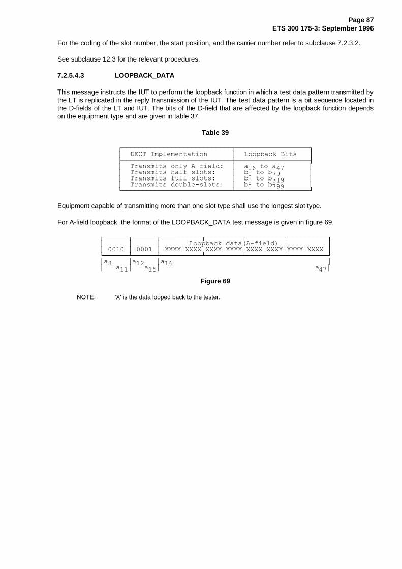
Page 87ETS 300 175-3: September 1996
For the coding of the slot number, the start position, and the carrier number refer to subclause 7.2.3.2.
See subclause 12.3 for the relevant procedures.
7.2.5.4.3 LOOPBACK_DATA
This message instructs the IUT to perform the loopback function in which a test data pattern transmitted bythe LT is replicated in the reply transmission of the IUT. The test data pattern is a bit sequence located inthe D-fields of the LT and IUT. The bits of the D-field that are affected by the loopback function dependson the equipment type and are given in table 37.
Table 39
¸¶¶¶¶¶¶¶¶¶¶¶¶¶¶¶¶¶¶¶¶¶¶¶¶¶¶¶¾¶¶¶¶¶¶¶¶¶¶¶¶¶¶¶¶¶¶¹·��'(&7�,PSOHPHQWDWLRQ������·��/RRSEDFN�%LWV���·¼¶¶¶¶¶¶¶¶¶¶¶¶¶¶¶¶¶¶¶¶¶¶¶¶¶¶¶À¶¶¶¶¶¶¶¶¶¶¶¶¶¶¶¶¶¶½·��7UDQVPLWV�RQO\�$�ILHOG���·��D���WR�D��������··��7UDQVPLWV�KDOI�VORWV�����·��E��WR�E���������··��7UDQVPLWV�IXOO�VORWV�����·��E��WR�E���������··��7UDQVPLWV�GRXEOH�VORWV���·��E��WR�E���������·º¶¶¶¶¶¶¶¶¶¶¶¶¶¶¶¶¶¶¶¶¶¶¶¶¶¶¶¿¶¶¶¶¶¶¶¶¶¶¶¶¶¶¶¶¶¶»
Equipment capable of transmitting more than one slot type shall use the longest slot type.
For A-field loopback, the format of the LOOPBACK_DATA test message is given in figure 69.
¸¶¶¶¶¶¶¾¶¶¶¶¶¶¾¶¶¶¶¶¶¶¶¶¶¾¶¶¶¶¶¶¶¶¶¾¶¶¶¶¶¶¶¶¶¾¶¶¶¶¶¶¶¶¶¶¹·������·������·�������/RRSEDFN�GDWD�$�ILHOG�������������··������·������·�;;;;�;;;;�;;;;�;;;;�;;;;�;;;;�;;;;�;;;;�·º¶¶¶¶¶¶¿¶¶¶¶¶¶¿¶¶¶¶¶¶¶¶¶¶¿¶¶¶¶¶¶¶¶¶¿¶¶¶¶¶¶¶¶¶¿¶¶¶¶¶¶¶¶¶¶»·D�����·D�����·D����������������������������������������··���D��·���D��·��������������������������������������D��·
Figure 69
NOTE: 'X' is the data looped back to the tester.
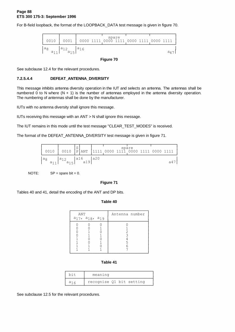
Page 88ETS 300 175-3: September 1996
For B-field loopback, the format of the LOOPBACK_DATA test message is given in figure 70.
¸¶¶¶¶¶¶¾¶¶¶¶¶¶¾¶¶¶¶¶¶¶¶¶¶¾¶¶¶¶¶¶¶¶¶¾¶¶¶¶¶¶¶¶¶¾¶¶¶¶¶¶¶¶¶¶¹·������·������·�������������VSDUH�����������������������··������·������·�����������������������������������������·º¶¶¶¶¶¶¿¶¶¶¶¶¶¿¶¶¶¶¶¶¶¶¶¶¿¶¶¶¶¶¶¶¶¶¿¶¶¶¶¶¶¶¶¶¿¶¶¶¶¶¶¶¶¶¶»·D�����·D�����·D����������������������������������������··���D��·���D��·��������������������������������������D��·
Figure 70
See subclause 12.4 for the relevant procedures.
7.2.5.4.4 DEFEAT_ANTENNA_DIVERSITY
This message inhibits antenna diversity operation in the IUT and selects an antenna. The antennas shall benumbered 0 to N where (N + 1) is the number of antennas employed in the antenna diversity operation.The numbering of antennas shall be done by the manufacturer.
IUTs with no antenna diversity shall ignore this message.
IUTs receiving this message with an ANT > N shall ignore this message.
The IUT remains in this mode until the test message "CLEAR_TEST_MODES" is received.
The format of the DEFEAT_ANTENNA_DIVERSITY test message is given in figure 71.
¸¶¶¶¶¶¶¾¶¶¶¶¶¶¾¶¾¶¶¶¶¾¶¶¶¶¾¶¶¶¶¶¶¶¶¶¾¶¶¶¶¶¶¶¶¶¾¶¶¶¶¶¶¶¶¶¶¹·������·������·6·����·������������VSDUH������������������··������·������·3·$17�·�����������������������������������·º¶¶¶¶¶¶¿¶¶¶¶¶¶¿¶¿¶¶¶¶¿¶¶¶¶¿¶¶¶¶¶¶¶¶¶¿¶¶¶¶¶¶¶¶¶¶¶¶¶¶¶¶¶¶¶¶»·D�����·D�����·D�����·D����������������������������������··���D��·���D��·���D��·��������������������������������D��·
NOTE: SP = spare bit = 0.
Figure 71
Tables 40 and 41, detail the encoding of the ANT and DP bits.
Table 40
¸¶¶¶¶¶¶¶¶¶¶¶¶¶¶¶¾¶¶¶¶¶¶¶¶¶¶¶¶¶¶¶¶¹·���$17���������·�$QWHQQD�QXPEHU�··�D����D����D���·����������������·¼¶¶¶¶¶¶¶¶¶¶¶¶¶¶¶À¶¶¶¶¶¶¶¶¶¶¶¶¶¶¶¶½·���������������·����������������··���������������·����������������··���������������·����������������··���������������·����������������··���������������·����������������··���������������·����������������··���������������·����������������··���������������·����������������·º¶¶¶¶¶¶¶¶¶¶¶¶¶¶¶¿¶¶¶¶¶¶¶¶¶¶¶¶¶¶¶¶»
Table 41
¸¶¶¶¶¶¶¶¾¶¶¶¶¶¶¶¶¶¶¶¶¶¶¶¶¶¶¶¶¶¶¶¶¶¶¶¶¹·�ELW���·���PHDQLQJ������������������·¼¶¶¶¶¶¶¶À¶¶¶¶¶¶¶¶¶¶¶¶¶¶¶¶¶¶¶¶¶¶¶¶¶¶¶¶½·�D�����·�UHFRJQLVH�4��ELW�VHWWLQJ���·º¶¶¶¶¶¶¶¿¶¶¶¶¶¶¶¶¶¶¶¶¶¶¶¶¶¶¶¶¶¶¶¶¶¶¶¶»
See subclause 12.5 for the relevant procedures.
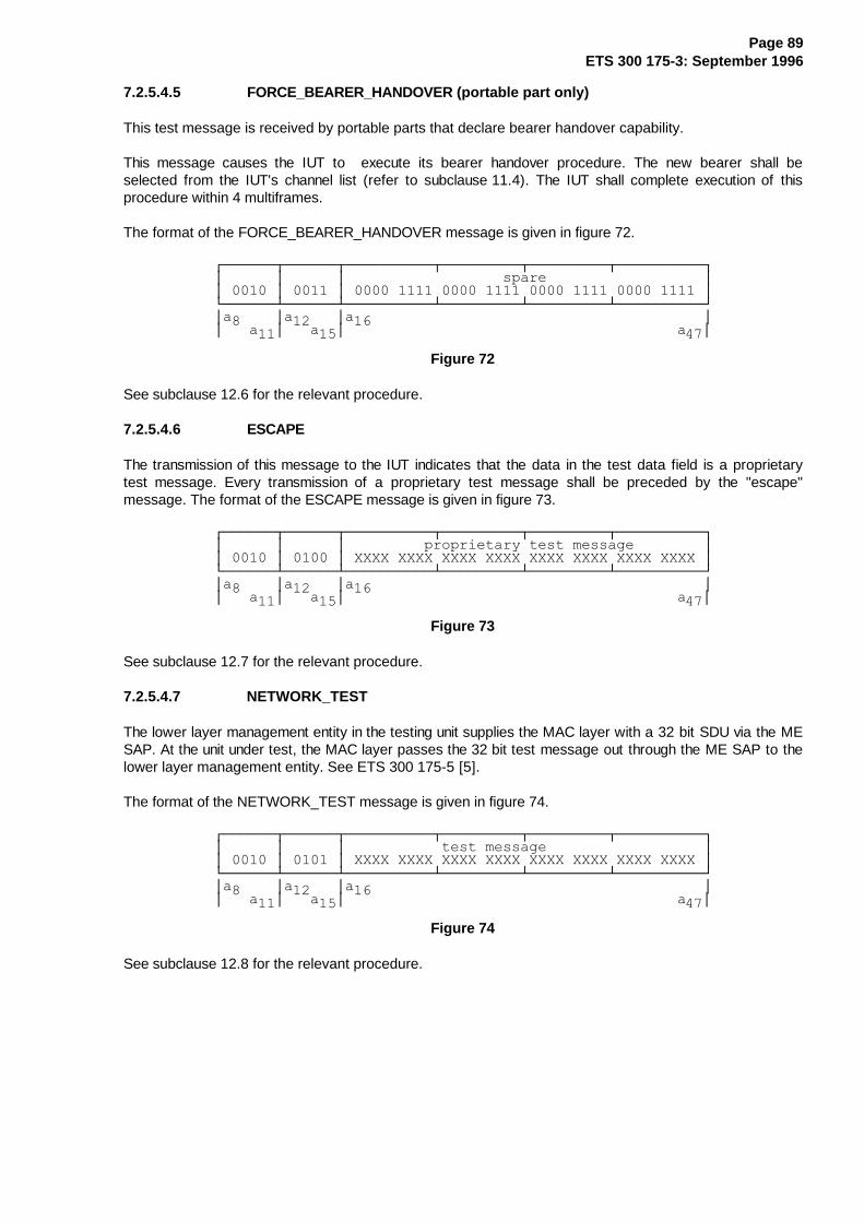
Page 89ETS 300 175-3: September 1996
7.2.5.4.5 FORCE_BEARER_HANDOVER (port able part only)
This test message is received by portable parts that declare bearer handover capability.
This message causes the IUT to execute its bearer handover procedure. The new bearer shall beselected from the IUT's channel list (refer to subclause 11.4). The IUT shall complete execution of thisprocedure within 4 multiframes.
The format of the FORCE_BEARER_HANDOVER message is given in figure 72.
¸¶¶¶¶¶¶¾¶¶¶¶¶¶¾¶¶¶¶¶¶¶¶¶¶¾¶¶¶¶¶¶¶¶¶¾¶¶¶¶¶¶¶¶¶¾¶¶¶¶¶¶¶¶¶¶¹·������·������·������������������VSDUH������������������··������·������·�����������������������������������������·º¶¶¶¶¶¶¿¶¶¶¶¶¶¿¶¶¶¶¶¶¶¶¶¶¿¶¶¶¶¶¶¶¶¶¿¶¶¶¶¶¶¶¶¶¿¶¶¶¶¶¶¶¶¶¶»·D�����·D�����·D����������������������������������������··���D��·���D��·��������������������������������������D��·
Figure 72
See subclause 12.6 for the relevant procedure.
7.2.5.4.6 ESCAPE
The transmission of this message to the IUT indicates that the data in the test data field is a proprietarytest message. Every transmission of a proprietary test message shall be preceded by the "escape"message. The format of the ESCAPE message is given in figure 73.
¸¶¶¶¶¶¶¾¶¶¶¶¶¶¾¶¶¶¶¶¶¶¶¶¶¾¶¶¶¶¶¶¶¶¶¾¶¶¶¶¶¶¶¶¶¾¶¶¶¶¶¶¶¶¶¶¹·������·������·���������SURSULHWDU\�WHVW�PHVVDJH��������··������·������·�;;;;�;;;;�;;;;�;;;;�;;;;�;;;;�;;;;�;;;;�·º¶¶¶¶¶¶¿¶¶¶¶¶¶¿¶¶¶¶¶¶¶¶¶¶¿¶¶¶¶¶¶¶¶¶¿¶¶¶¶¶¶¶¶¶¿¶¶¶¶¶¶¶¶¶¶»·D�����·D�����·D����������������������������������������··���D��·���D��·��������������������������������������D��·
Figure 73
See subclause 12.7 for the relevant procedure.
7.2.5.4.7 NETWORK_TEST
The lower layer management entity in the testing unit supplies the MAC layer with a 32 bit SDU via the MESAP. At the unit under test, the MAC layer passes the 32 bit test message out through the ME SAP to thelower layer management entity. See ETS 300 175-5 [5].
The format of the NETWORK_TEST message is given in figure 74.
¸¶¶¶¶¶¶¾¶¶¶¶¶¶¾¶¶¶¶¶¶¶¶¶¶¾¶¶¶¶¶¶¶¶¶¾¶¶¶¶¶¶¶¶¶¾¶¶¶¶¶¶¶¶¶¶¹·������·������·�����������WHVW�PHVVDJH������������������··������·������·�;;;;�;;;;�;;;;�;;;;�;;;;�;;;;�;;;;�;;;;�·º¶¶¶¶¶¶¿¶¶¶¶¶¶¿¶¶¶¶¶¶¶¶¶¶¿¶¶¶¶¶¶¶¶¶¿¶¶¶¶¶¶¶¶¶¿¶¶¶¶¶¶¶¶¶¶»·D�����·D�����·D����������������������������������������··���D��·���D��·��������������������������������������D��·
Figure 74
See subclause 12.8 for the relevant procedure.
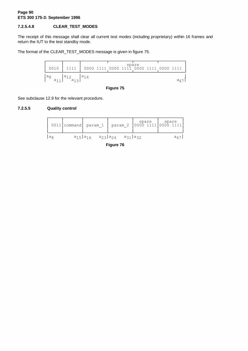
Page 90ETS 300 175-3: September 1996
7.2.5.4.8 CLEAR_TEST_MODES
The receipt of this message shall clear all current test modes (including proprietary) within 16 frames andreturn the IUT to the test standby mode.
The format of the CLEAR_TEST_MODES message is given in figure 75.
¸¶¶¶¶¶¶¾¶¶¶¶¶¶¾¶¶¶¶¶¶¶¶¶¶¾¶¶¶¶¶¶¶¶¶¾¶¶¶¶¶¶¶¶¶¾¶¶¶¶¶¶¶¶¶¶¹·������·������·������������������VSDUH������������������··������·������·�����������������������������������������·º¶¶¶¶¶¶¿¶¶¶¶¶¶¿¶¶¶¶¶¶¶¶¶¶¿¶¶¶¶¶¶¶¶¶¿¶¶¶¶¶¶¶¶¶¿¶¶¶¶¶¶¶¶¶¶»·D�����·D�����·D����������������������������������������··���D��·���D��·��������������������������������������D��·
Figure 75
See subclause 12.9 for the relevant procedure.
7.2.5.5 Quality control
¸¶¶¶¶¶¾¶¶¶¶¶¶¶¾¶¶¶¶¶¶¶¶¶¾¶¶¶¶¶¶¶¶¶¾¶¶¶¶¶¶¶¶¶¾¶¶¶¶¶¶¶¶¶¹·�����·�������·���������·���������·��VSDUH��·��VSDUH��··�����·FRPPDQG·�SDUDPB��·�SDUDPB��·���������·���������··�����·�������·���������·���������·���������·���������·º¶¶¶¶¶¿¶¶¶¶¶¶¶¿¶¶¶¶¶¶¶¶¶¿¶¶¶¶¶¶¶¶¶¿¶¶¶¶¶¶¶¶¶¿¶¶¶¶¶¶¶¶¶»·D���������D��·D�����D��·D�����D��·D���������������D��·
Figure 76

Page 91ETS 300 175-3: September 1996
Table 42
¸¶¶¶¶¶¶¶¶¾¶¶¶¶¶¶¶¶¶¶¶¾¶¶¶¶¶¶¶¶¶¶¶¾¶¶¶¶¶¶¶¶¶¶¶¶¶¶¶¶¶¶¶¶¶¶¶¶¶¶¶¶¹·�FRPPDQG·��SDUDPB���·��SDUDPB���·��������0HDQLQJ�������������·¼¶¶¶¶¶¶¶¶À¶¶¶¶¶¶¶¶¶¶¶À¶¶¶¶¶¶¶¶¶¶¶À¶¶¶¶¶¶¶¶¶¶¶¶¶¶¶¶¶¶¶¶¶¶¶¶¶¶¶¶½·��������·������/%1��·�����������·�DQWHQQD�VZLWFK�IRU�WKH�����··��������·�����������·�����������·���VLQJOH�EHDUHU�LGHQWLILHG�··��������·�����������·�����������·���E\�/%1�������������������··��������·�����������·�����������·�UHTXHVW��37���!�)7���������··��������·�����������·�����������·�UHMHFW���)7���!�37���������··��������·�����������·�����������·����������������������������··��������·����531����·�����������·�DQWHQQD�VZLWFK�IRU�DOO�����··��������·�����������·�����������·���EHDUHUV�RI�WKLV�FRQQHF���··��������·�����������·�����������·���WLRQ�WR�WKH�5)3�LGHQWL���··��������·�����������·�����������·���ILHG�E\�LWV�531����������··��������·�����������·�����������·�UHTXHVW��37���!�)7���������··��������·�����������·�����������·�UHMHFW���)7���!�37���������··��������·�����������·�����������·����������������������������··��������·������/%1��·�����������·�EHDUHU�KDQGRYHU�RI�WKH�����··��������·�����������·����RU�����·���EHDUHU�LGHQWLILHG�E\�/%1�··��������·�����������·����531����·�UHTXHVW��)7���!�37���������··��������·�����������·�����������·�UHMHFW���37���!�)7���������··��������·�����������·�����������·����������������������������··��������·�����������·�����������·�FRQQHFWLRQ�KDQGRYHU��������··��������·�����������·�����������·�UHTXHVW��)7���!�37���������··��������·�����������·�����������·�UHMHFW���37���!�)7���������··��������·�����������·�����������·����������������������������··��������·������/%1��·�IUHTXHQF\�·�IUHTXHQF\�FRQWURO�IRU�WKH��··��������·�����������·�HUURU�����·���EHDUHU�LGHQWLILHG�E\�/%1�··��������·�����������·�����������·�UHTXHVW��)7���!�37���������··��������·�����������·�����������·�UHMHFW���37���!�)7���������··��������·�����������·�����������·����������������������������··��������·����531����·�IUHTXHQF\�·�IUHTXHQF\�FRQWURO�IRU�DOO��··��������·�����������·�HUURU�����·���EHDUHUV�RI�WKLV�FRQQHF���··��������·�����������·�����������·���WLRQ�WR�WKH�5)3�LGHQWL���··��������·�����������·�����������·���ILHG�E\�LWV�531����������··��������·�����������·�����������·�UHTXHVW��)7���!�37���������··��������·�����������·�����������·�UHMHFW���37���!�)7���������··��������·�����������·�����������·����������������������������··��������·����531����·�DGYDQFH���·�$GYDQFH�WLPLQJ�IRU�DOO�WKH�··��������·�����������·�WLPLQJ����·���EHDUHUV�RI�WKLV�FRQQHF���··��������·�����������·LQFUHPHQW��·���WLRQ�WR�WKH�5)3�LGHQWL���··��������·�����������·GHFUHPHQW��·���ILHG�E\�LWV�531����������··��������·�����������·�����������·�UHTXHVW��)7���!�37���������··��������·�����������·�����������·�UHMHFW���37���!�)7���������··��������·�����������·�����������·����������������������������··��������·����531����·�����������·7KH�33�LQIRUPV�WKH�)7�WKDW��··��������·�����������·�����������·SURORQJHG�SUHDPEOH�LV�LPS���··��������·�����������·�����������·OHPHQWHG�IRU�DOO�WKH�EHDUHUV··��������·�����������·�����������·RI�WKLV�FRQQHFWLRQ�WR�WKH���··��������·�����������·�����������·5)3�LGHQWLILHG�E\�LWV�531���··��������·�����������·�����������·�UHTXHVW��37���!�)7���������··��������·�����������·�����������·�UHMHFW���)7���!�37���������··��������·�����������·�����������·����������������������������··��������·�����������·�����������·����������������������������··���WR���·�����������·�����������·���UHVHUYHG�����������������··��������·�����������·�����������·����������������������������·º¶¶¶¶¶¶¶¶¿¶¶¶¶¶¶¶¶¶¶¶¿¶¶¶¶¶¶¶¶¶¶¶¿¶¶¶¶¶¶¶¶¶¶¶¶¶¶¶¶¶¶¶¶¶¶¶¶¶¶¶¶»
NOTE 1: The function of these commands depends on the transmission direction. Thecommands are either requests or rejects. A reject should only be used if the requestedaction is not supported.
NOTE 2: For basic connections LBN is set to 1111.
NOTE 3: All other values for bits a16 to a47 inclusive are reserved. Potential uses include RSSIreporting, synchronisation word correlation report, clock jitter report, etc.
NOTE 4: For the bearer handover request, the RPN is an optional parameter. If set to all "0" theFP does not propose a particular RFP for handover.
NOTE 5: A PP may or may not accept the RFP's proposal of the new RPN.
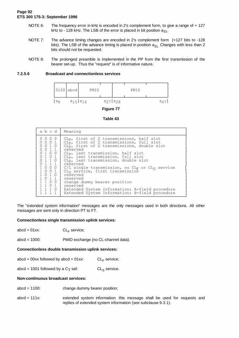
Page 92ETS 300 175-3: September 1996
NOTE 6: The frequency error in kHz is encoded in 2's complement form, to give a range of + 127kHz to - 128 kHz. The LSB of the error is placed in bit position a31.
NOTE 7: The advance timing changes are encoded in 2's complement form (+127 bits to -128bits). The LSB of the advance timing is placed in position a31. Changes with less than 2bits should not be requested.
NOTE 8: The prolonged preamble is implemented in the PP from the first transmission of thebearer set-up. Thus the "request" is of informative nature.
7.2.5.6 Broadcast and connectionless services
¸¶¶¶¶¾¶¶¶¶¾¶¶¶¶¶¶¶¶¾¶¶¶¶¾¶¶¶¶¾¶¶¶¶¶¶¶¶¾¶¶¶¶¶¶¶¶¹·����·����·�������������·����������������������··����·DEFG·����)0,'�����·�������30,'�����������··����·����·�������������·����������������������·º¶¶¶¶¿¶¶¶¶¿¶¶¶¶¶¶¶¶¿¶¶¶¶¿¶¶¶¶¿¶¶¶¶¶¶¶¶¿¶¶¶¶¶¶¶¶»·D�����D��·D���������D��·D������������������D��·
Figure 77
Table 43
¸¶¶¶¶¶¶¶¶¶¾¶¶¶¶¶¶¶¶¶¶¶¶¶¶¶¶¶¶¶¶¶¶¶¶¶¶¶¶¶¶¶¶¶¶¶¶¶¶¶¶¶¶¶¶¶¶¶¶¶¶¶¹·�D�E�F�G�·�0HDQLQJ�������������������������������������������·¼¶¶¶¶¶¶¶¶¶À¶¶¶¶¶¶¶¶¶¶¶¶¶¶¶¶¶¶¶¶¶¶¶¶¶¶¶¶¶¶¶¶¶¶¶¶¶¶¶¶¶¶¶¶¶¶¶¶¶¶¶½·���������·�&/)��ILUVW�RI���WUDQVPLVVLRQV��KDOI�VORW����������··���������·�&/)��ILUVW�RI���WUDQVPLVVLRQV��IXOO�VORW����������··���������·�&/)��ILUVW�RI���WUDQVPLVVLRQV��GRXEOH�VORW��������··���������·�UHVHUYHG������������������������������������������··���������·�&/)��ODVW�WUDQVPLVVLRQ��KDOI�VORW�����������������··���������·�&/)��ODVW�WUDQVPLVVLRQ��IXOO�VORW�����������������··���������·�&/)��ODVW�WUDQVPLVVLRQ��GRXEOH�VORW���������������··���������·�UHVHUYHG������������������������������������������··���������·�&�/�VLQJOH�WUDQVPLVVLRQ��QR�&/)�RU�&/6�VHUYLFH����··���������·�&/6�VHUYLFH��ILUVW�WUDQVPLVVLRQ�������������������··���������·�UHVHUYHG������������������������������������������··���������·�UHVHUYHG������������������������������������������··���������·�FKDQJH�GXPP\�EHDUHU�SRVLWLRQ����������������������··���������·�UHVHUYHG������������������������������������������··���������·�([WHQGHG�6\VWHP�,QIRUPDWLRQ��$�ILHOG�SURFHGXUH����··���������·�([WHQGHG�6\VWHP�,QIRUPDWLRQ��%�ILHOG�SURFHGXUH����·º¶¶¶¶¶¶¶¶¶¿¶¶¶¶¶¶¶¶¶¶¶¶¶¶¶¶¶¶¶¶¶¶¶¶¶¶¶¶¶¶¶¶¶¶¶¶¶¶¶¶¶¶¶¶¶¶¶¶¶¶¶»
The "extended system information" messages are the only messages used in both directions. All othermessages are sent only in direction PT to FT.
Connectionless single transmission uplink services:
abcd = 01xx: CLF service;
abcd = 1000: PMID exchange (no CL-channel data).
Connectionless double transmission uplink services:
abcd = 00xx followed by abcd = 01xx: CLF service;
abcd = 1001 followed by a CT tail: CLS service.
Non-continuous broadcast services:
abcd = 1100: change dummy bearer position;
abcd = 111x: extended system information: this message shall be used for requests andreplies of extended system information (see subclause 9.3.1).

Page 93ETS 300 175-3: September 1996
7.2.5.7 Encryption control
¸¶¶¶¶¾¶¶¶¶¶¶¾¶¶¶¶¶¶¶¶¾¶¶¶¶¾¶¶¶¶¾¶¶¶¶¶¶¶¶¾¶¶¶¶¶¶¶¶¹·����·�FRP��·�������������·����������������������··����·�PDQG�·�����)0,'����·��������30,'����������··����·������·�������������·����������������������·º¶¶¶¶¿¶¶¶¶¶¶¿¶¶¶¶¶¶¶¶¿¶¶¶¶¿¶¶¶¶¿¶¶¶¶¶¶¶¶¿¶¶¶¶¶¶¶¶»·D���·D�����·D������������·D���������������������··�D��·���D��·����������D��·�������������������D��·
Figure 78
Table 44
¸¶¶¶¶¶¶¶¶¾¶¶¶¶¶¶¶¶¶¶¶¶¶¶¶¶¶¶¹·FRPPDQG�·�0HVVDJH����������·¼¶¶¶¶¶¶¶¶À¶¶¶¶¶¶¶¶¶¶¶¶¶¶¶¶¶¶½·����[[��·�VWDUW�HQFU\SWLRQ�··����[[��·�VWRS�HQFU\SWLRQ��··����[[��·�UHVHUYHG���������··����[[��·�UHVHUYHG���������··��[[����·�UHTXHVW����������··��[[����·�FRQILUP����������··��[[����·�JUDQW������������··��[[����·�UHVHUYHG���������·º¶¶¶¶¶¶¶¶¿¶¶¶¶¶¶¶¶¶¶¶¶¶¶¶¶¶¶»
7.2.5.8 B-field setup, first PT transmission
¸¶¶¶¶¾¶¶¶¶¾¶¶¶¶¶¶¶¶¶¶¾¶¶¶¶¶¶¶¶¶¶¶¾¶¶¶¶¶¶¶¶¶¾¶¶¶¶¶¶¶¶¶¶¹·����·������������������������������������������������··����·�����OHDVW�VLJQLILFDQW����ELWV�RI�5)3,����������··����·������������������������������������������������·º¶¶¶¶¿¶¶¶¶¿¶¶¶¶¶¶¶¶¶¶¿¶¶¶¶¶¿¶¶¶¶¶¿¶¶¶¶¶¶¶¶¶¿¶¶¶¶¶¶¶¶¶¶»·D���·D��������������������������������������������D��·
Figure 79
This message shall only be used for the first transmission on a new physical channel and only by PTs. Itmay be used by PTs to ensure that an RFP that is capable of both A- and B-field setups uses the B-fieldsetup procedures.
7.2.5.9 Escape
¸¶¶¶¶¶¶¾¶¶¶¶¾¶¶¶¶¶¶¶¶¶¾¶¶¶¶¶¶¶¶¶¾¶¶¶¶¶¶¶¶¶¾¶¶¶¶¶¶¶¶¶¹·������·��������������������������������������������··������·����HVFDSH�LQIRUPDWLRQ����������������������··������·��������������������������������������������·º¶¶¶¶¶¶¿¶¶¶¶¿¶¶¶¶¶¶¶¶¶¿¶¶¶¶¶¶¶¶¶¿¶¶¶¶¶¶¶¶¶¿¶¶¶¶¶¶¶¶¶»·D�����·D�������������������������������������������··���D��·�����������������������������������������D��·
Figure 80
Any DECT equipment may transmit an escape message.
The content of the escape information field (a36 to a47) is not specified. This message is provided forapplication specific use.
7.2.5.10 TARI message
The message is assumed to be a "request" when transmitted in direction PT to FT, and to be a "reply"when transmitted in direction FT to PT.
¸¶¶¶¶¾¶¶¶¶¾¶¶¶¶¶¶¶¶¾¶¶¶¶¶¶¶¶¾¶¶¶¶¶¶¶¶¾¶¶¶¶¶¶¶¶¹·����·����·������7$5,�ILHOG�������������������·º¶¶¶¶¿¶¶¶¶¿¶¶¶¶¶¶¶¶¿¶¶¶¶¶¶¶¶¿¶¶¶¶¶¶¶¶¿¶¶¶¶¶¶¶¶»·D���·D������������������������������������D��·
Figure 81

Page 94ETS 300 175-3: September 1996
The management entity in the transmitting radio endpoint supplies the MAC layer with a 36 bit SDU via theME SAP. At the receiving endpoint the MAC layer passes the 36 bit SDU out through the ME SAP to themanagement entity.
For the coding of the TARI field refer to ETS 300 175-6 [6].
7.2.5.11 REP connection control
7.2.5.11.1 General
The REP connection control messages shall be used to establish a duplex bearer and to create a doubleduplex bearer.
7.2.5.11.2 Format for most messages
¸¶¶¶¶¶¶¶¶¶¶¶¾¶¶¶¶¶¶¶¶¶¶¶¾¶¶¶¶¶¶¶¶¶¶¶¾¶¶¶¶¶¶¶¶¶¶¶¹·�����������·��FRPPDQG��·���)0,'����·����30,'���·¼¶¶¶¶¶¶¶¶¶¶¶À¶¶¶¶¶¶¶¶¶¶¶À¶¶¶¶¶¶¶¶¶¶¶À¶¶¶¶¶¶¶¶¶¶¶½·���D�������·��D��������·���D�������·�D�����D���·º¶¶¶¶¶¶¶¶¶¶¶¿¶¶¶¶¶¶¶¶¶¶¶¿¶¶¶¶¶¶¶¶¶¶¶¿¶¶¶¶¶¶¶¶¶¶¶»
NOTE: For definitions of FMID and PMID, see subclause 11.7.
Figure 82
Table 45
¸¶¶¶¶¶¶¶¶¶¾¶¶¶¶¶¶¶¶¶¶¶¶¶¶¶¶¶¶¶¶¶¶¶¶¶¶¶¶¶¶¶¶¶¶¶¶¶¶¶¶¶¶¶¶¶¶¶¶¶¶¶¹·�FRPPDQG�·����������5(3�FRQQHFWLRQ�FRQWURO�PHVVDJHV����������·¼¶¶¶¶¶¶¶¶¶À¶¶¶¶¶¶¶¶¶¶¶¶¶¶¶¶¶¶¶¶¶¶¶¶¶¶¶¶¶¶¶¶¶¶¶¶¶¶¶¶¶¶¶¶¶¶¶¶¶¶¶½·���������·�5(3BDFFHVVBUHTXHVW���������������������������� ���··���������·�5(3BEHDUHUBKDQGRYHUBUHTXHVW������������������� ���··���������·�5(3BEHDUHUBFRQILUP��������������������������������··���������·�5(3BZDLW������������������������������������������··���������·�5(3BUHOHDVH���������������������������������������··���������·�5(3BFKDQQHOBPDSBUHTXHVW���������������������������··���������·�5(3BFKDQQHOBPDSBFRQILUP���������������������������·¼¶¶¶¶¶¶¶¶¶À¶¶¶¶¶¶¶¶¶¶¶¶¶¶¶¶¶¶¶¶¶¶¶¶¶¶¶¶¶¶¶¶¶¶¶¶¶¶¶¶¶¶¶¶¶¶¶¶¶¶¶½·���������·� �LQGLFDWHV�PHVVDJHV�WKDW�XVH�WKH�ILUVW��37�WUDQV�··���������·�PLVVLRQ��FRGH��2WKHU�PHVVDJHV�XVH�WKH�QRUPDO������··���������·�07�FRGH�������������������������������������������·º¶¶¶¶¶¶¶¶¶¿¶¶¶¶¶¶¶¶¶¶¶¶¶¶¶¶¶¶¶¶¶¶¶¶¶¶¶¶¶¶¶¶¶¶¶¶¶¶¶¶¶¶¶¶¶¶¶¶¶¶¶»
For REP_channel_map.req and REP_channel_map.cfm messages the format is defined in figures 83 and84.
7.2.5.11.3 REP CHANNEL MAP REQUEST:
¸¶¶¶¶¶¶¾¶¶¶¶¶¶¾¶¶¶¶¶¶¾¶¶¶¶¶¶¾¶¶¶¶¶¶¾¶¶¶¶¶¶¾¶¶¶¶¶¶¹·������·������·��61��·��&1��·�)0,'�·��61��·��&1��·¼¶¶¶¶¶¶À¶¶¶¶¶¶À¶¶¶¶¶¶À¶¶¶¶¶¶À¶¶¶¶¶¶À¶¶¶¶¶¶À¶¶¶¶¶¶··D�����·D�����·�D����·�D����·�D����·�D����·D��D��·º¶¶¶¶¶¶¿¶¶¶¶¶¶¿¶¶¶¶¶¶¿¶¶¶¶¶¶¿¶¶¶¶¶¶¿¶¶¶¶¶¶¿¶¶¶¶¶¶»
Figure 83
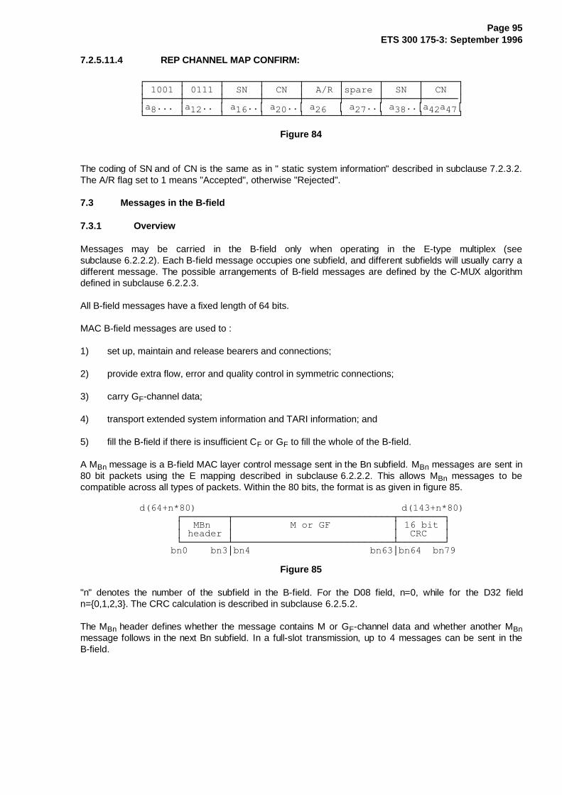
Page 95ETS 300 175-3: September 1996
7.2.5.11.4 REP CHANNEL MAP CONFIRM:
¸¶¶¶¶¶¶¾¶¶¶¶¶¶¾¶¶¶¶¶¶¾¶¶¶¶¶¶¾¶¶¶¶¶¶¾¶¶¶¶¶¶¾¶¶¶¶¶¶¾¶¶¶¶¶¶¹·������·������·��61��·��&1��·��$�5�·VSDUH�·��61��·��&1��·¼¶¶¶¶¶¶À¶¶¶¶¶¶À¶¶¶¶¶¶À¶¶¶¶¶¶À¶¶¶¶¶¶À¶¶¶¶¶¶À¶¶¶¶¶¶À¶¶¶¶¶¶··D�����·D�����·�D����·�D����·�D����·�D����·�D����·D��D��·º¶¶¶¶¶¶¿¶¶¶¶¶¶¿¶¶¶¶¶¶¿¶¶¶¶¶¶¿¶¶¶¶¶¶¿¶¶¶¶¶¶¿¶¶¶¶¶¶¿¶¶¶¶¶¶»
Figure 84
The coding of SN and of CN is the same as in " static system information" described in subclause 7.2.3.2.The A/R flag set to 1 means "Accepted", otherwise "Rejected".
7.3 Messages in the B-field
7.3.1 Overview
Messages may be carried in the B-field only when operating in the E-type multiplex (seesubclause 6.2.2.2). Each B-field message occupies one subfield, and different subfields will usually carry adifferent message. The possible arrangements of B-field messages are defined by the C-MUX algorithmdefined in subclause 6.2.2.3.
All B-field messages have a fixed length of 64 bits.
MAC B-field messages are used to :
1) set up, maintain and release bearers and connections;
2) provide extra flow, error and quality control in symmetric connections;
3) carry GF-channel data;
4) transport extended system information and TARI information; and
5) fill the B-field if there is insufficient CF or GF to fill the whole of the B-field.
A MBn message is a B-field MAC layer control message sent in the Bn subfield. MBn messages are sent in80 bit packets using the E mapping described in subclause 6.2.2.2. This allows MBn messages to becompatible across all types of packets. Within the 80 bits, the format is as given in figure 85.
G����Q ���������������������������������������G�����Q �������¸¶¶¶¶¶¶¶¶¾¶¶¶¶¶¶¶¶¶¶¶¶¶¶¶¶¶¶¶¶¶¶¶¶¶¶¶¶¾¶¶¶¶¶¶¶¶¹����·��0%Q���·����������0�RU�*)�����������·����ELW�·����·�KHDGHU�·����������������������������·��&5&���·����º¶¶¶¶¶¶¶¶¿¶¶¶¶¶¶¶¶¶¶¶¶¶¶¶¶¶¶¶¶¶¶¶¶¶¶¶¶¿¶¶¶¶¶¶¶¶»����EQ�����EQ�·EQ����������������������EQ��·EQ����EQ��
Figure 85
"n" denotes the number of the subfield in the B-field. For the D08 field, n=0, while for the D32 fieldn={0,1,2,3}. The CRC calculation is described in subclause 6.2.5.2.
The MBn header defines whether the message contains M or GF-channel data and whether another MBnmessage follows in the next Bn subfield. In a full-slot transmission, up to 4 messages can be sent in theB-field.

Page 96ETS 300 175-3: September 1996
Table 46
¸¶¶¶¶¶¶¶¶¾¶¶¶¶¶¶¶¶¶¶¶¶¶¶¶¶¶¶¶¶¶¶¶¶¶¶¶¶¶¶¶¶¶¶¶¶¶¶¹·��0%Q���·��0HVVDJH�W\SH������������������������··�KHDGHU�·��������������������������������������·¼¶¶¶¶¶¶¶¶À¶¶¶¶¶¶¶¶¶¶¶¶¶¶¶¶¶¶¶¶¶¶¶¶¶¶¶¶¶¶¶¶¶¶¶¶¶¶½·��;�����·�UHVHUYHG�����������������������������··��;�����·�DGYDQFHG�FRQQHFWLRQ�FRQWURO����������··��;�����·�QXOO���������������������������������··��;�����·�TXDOLW\�FRQWURO����������������������··��;�����·�H[WHQGHG�V\VWHP�LQIRUPDWLRQ����������··��;�����·�*)�FKDQQHO�GDWD�SDFNHW���������������··��;�����·�UHVHUYHG�����������������������������··��;�����·�HVFDSH�������������������������������·º¶¶¶¶¶¶¶¶¿¶¶¶¶¶¶¶¶¶¶¶¶¶¶¶¶¶¶¶¶¶¶¶¶¶¶¶¶¶¶¶¶¶¶¶¶¶¶»
For full slots:
X = 1: subfield B(n+1) exists and contains a MBn message or subfield B(n) is the last subfield in this slot;
X = 0: subfields B(n+1) to B3, inclusive, contain CF or CLF data.
For half slots:
X = 1.
For double slots:
X = 1: subfield B(n+1) exists and contains a MBn message or subfield B(n) is the last subfield in this slot;
X = 0: subfields B(n+1) to B9, inclusive, contain CF or CLF data.
7.3.2 Slot type encoding
Table 47
¸¶¶¶¶¶¶¶¶¶¶¶¶¾¶¶¶¶¶¶¶¶¶¶¶¶¶¶¶¶¶¶¶¶¹·��VORW�W\SH�·�0HDQLQJ������������·¼¶¶¶¶¶¶¶¶¶¶¶¶À¶¶¶¶¶¶¶¶¶¶¶¶¶¶¶¶¶¶¶¶½·������������·�QRUPDO�IXOO�VORW���··������������·�KDOI�VORW�ZLWK�M ��··������������·�GRXEOH�VORW��������··�DOO�RWKHUV�·�UHVHUYHG�����������·º¶¶¶¶¶¶¶¶¶¶¶¶¿¶¶¶¶¶¶¶¶¶¶¶¶¶¶¶¶¶¶¶¶»
NOTE: If the slot type or j value is not implementable at the destination, a release is sent,preferably with the "reasons for release" field completed.
7.3.3 Advanced connection control
7.3.3.1 General format
¸¶¶¶¶¶¶¶¶¾¶¶¶¶¶¶¶¶¶¾¶¶¶¶¶¶¶¶¶¶¶¶¶¶¶¶¶¶¶¶¶¶¶¶¶¶¶¶¶¶¹·��;�����·�FRPPDQG�·���������LQIRUPDWLRQ����������·º¶¶¶¶¶¶¶¶¿¶¶¶¶¶¶¶¶¶¿¶¶¶¶¶¶¶¶¶¶¶¶¶¶¶¶¶¶¶¶¶¶¶¶¶¶¶¶¶¶»·EQ���EQ�·EQ����EQ�·EQ������������������������EQ��·
Figure 86

Page 97ETS 300 175-3: September 1996
Table 48
¸¶¶¶¶¶¶¶¶¾¶¶¶¶¶¶¶¶¶¶¶¶¶¶¶¶¶¶¶¶¶¶¶¶¶¶¶¶¶¶¶¶¶¶¶¶¶¶¶¹·FRPPDQG�·�$GYDQFHG�FRQQHFWLRQ�FRQWURO�PHVVDJHV��·¼¶¶¶¶¶¶¶¶À¶¶¶¶¶¶¶¶¶¶¶¶¶¶¶¶¶¶¶¶¶¶¶¶¶¶¶¶¶¶¶¶¶¶¶¶¶¶¶½·��������·�$&&(66B5(48(67��������������������� �··��������·�EHDUHUBKDQGRYHUBUHTXHVW������������ �··��������·�FRQQHFWLRQBKDQGRYHUBUHTXHVW�������� �··��������·�XQFRQILUPHGBDFFHVVBUHTXHVW��������� �··��������·�EHDUHUBFRQILUP������������������������··��������·�ZDLW����������������������������������··��������·�DWWULEXWHVB%�UHTXHVW������������������··��������·�DWWULEXWHVB%�FRQILUP������������������··��������·�EDQGZLGWKB%�UHTXHVW�������������������··��������·�EDQGZLGWKB%�FRQILUP�������������������··��������·�FKDQQHOBOLVW��������������������������··��������·�XQFRQILUPHGBGXPP\������������������ �··��������·�XQFRQILUPHGBKDQGRYHU��������������� �··��������·�UHVHUYHG������������������������������··��������·�UHVHUYHG������������������������������··��������·�UHOHDVH�������������������������������·¼¶¶¶¶¶¶¶¶¿¶¶¶¶¶¶¶¶¶¶¶¶¶¶¶¶¶¶¶¶¶¶¶¶¶¶¶¶¶¶¶¶¶¶¶¶¶¶¶½·�� �LQGLFDWHV�PHVVDJHV��WKDW�LI�WUDQVPLWWHG�E\�··�����D�37��XVH�WKH��ILUVW�37�WUDQVPLVVLRQ��FRGH�·º¶¶¶¶¶¶¶¶¶¶¶¶¶¶¶¶¶¶¶¶¶¶¶¶¶¶¶¶¶¶¶¶¶¶¶¶¶¶¶¶¶¶¶¶¶¶¶¶»
The FT may use the messages indicated with ** without the "first PT transmission" code.
7.3.3.2 BEARER_REQUEST
¸¶¶¶¶¶¶¾¶¶¶¾¶¶¾¶¾¶¾¶¶¾¶¶¾¶¶¶¶¾¶¶¶¶¾¶¶¶¶¶¾¶¶¶¶¾¶¶¶¶¾¶¶¶¶¶¾¶¶¶¶¹·������·,�%·����·�������·����·����·�XS��·�VHU·PD[�·VORW�·VSU�··;�����·�&�·)0,'·�30,'��·(&1�·/%1�·GRZQ�·W\SH·OLIH·W\SH�·����··������·�1�·����·�������·����·����·VP�VV·����·����·�����·����·º¶¶¶¶¶¶¿¶¶¶¿¶¶¿¶¿¶¿¶¶¿¶¶¿¶¶¶¶¿¶¶¶¶¿¶¶¶¶¶¿¶¶¶¶¿¶¶¶¶¿¶¶¶¶¶¿¶¶¶¶»·EQ����·EQ�·EQ��·EQ�����·EQ��·EQ��·EQ���·EQ��·EQ��·EQ���·EQ��··���EQ�·EQ�·EQ��·���EQ��·EQ��·EQ��·�EQ��·EQ��·EQ��·�EQ��·EQ��·
Figure 87
Table 49
¸¶¶¶¶¶¶¶¶¶¶¶¶¶¶¶¾¶¶¶¶¶¶¶¶¶¶¶¶¶¶¶¶¶¶¶¶¶¶¶¶¶¶¶¶¶¹·�,���%���&���1�·�����������������������������··�����E���E�����·�0HDQLQJ���������������������·¼¶¶¶¶¶¶¶¶¶¶¶¶¶¶¶À¶¶¶¶¶¶¶¶¶¶¶¶¶¶¶¶¶¶¶¶¶¶¶¶¶¶¶¶¶½·���������������·�DFFHVVBUHTXHVW��������������··���������������·�EHDUHUBKDQGRYHUBUHTXHVW�����··���������������·�FRQQHFWLRQBKDQGRYHUBUHTXHVW�··���������������·�XQFRQILUPHGBDFFHVVBUHTXHVW��·º¶¶¶¶¶¶¶¶¶¶¶¶¶¶¶¿¶¶¶¶¶¶¶¶¶¶¶¶¶¶¶¶¶¶¶¶¶¶¶¶¶¶¶¶¶»
For the coding of bits b40 ... b59, see subclause 7.2.5.3.8.
PMID = Portable part MAC layer IDentity (refer to subclause 11.7);
FMID = Fixed part MAC layer IDentity (refer to subclause 11.7).
7.3.3.3 BEARER_CONFIRM
¸¶¶¶¶¶¶¶¶¶¶¾¶¶¾¶¾¶¾¶¶¾¶¶¾¶¶¶¶¾¶¶¶¶¾¶¶¶¶¶¾¶¶¶¶¾¶¶¶¶¾¶¶¶¶¶¾¶¶¶¶¹·����������·����·�������·����·����·�XS��·�VHU·PD[�·VORW�·VSU�··;���������·)0,'·�30,'��·(&1�·/%1�·GRZQ�·W\SH·OLIH·W\SH�·����··����������·����·�������·����·����·VP�VV·����·����·�����·����·º¶¶¶¶¶¶¶¶¶¶¿¶¶¿¶¿¶¿¶¶¿¶¶¿¶¶¶¶¿¶¶¶¶¿¶¶¶¶¶¿¶¶¶¶¿¶¶¶¶¿¶¶¶¶¶¿¶¶¶¶»·EQ��������·EQ��·EQ�����·EQ��·EQ��·EQ���·EQ��·EQ��·EQ���·EQ��··�������EQ�·EQ��·���EQ��·EQ��·EQ��·�EQ��·EQ��·EQ��·�EQ��·EQ��·
Figure 88
For the coding of bits b40 ... b59, see subclause 7.2.5.3.8.

Page 98ETS 300 175-3: September 1996
7.3.3.4 WAIT
¸¶¶¶¶¶¶¶¶¶¾¶¶¶¾¶¶¾¶¶¶¶¾¶¶¶¶¶¶¶¾¶¶¶¶¶¶¶¾¶¶¶¶¶¶¶¶¾¶¶¶¶¶¾¶¶¶¶¶¶¶¹·���������·������·�������30,'���������·����������������������··;��������·�)0,'�·�����RU�VSDUH�������·��������VSDUH���������··���������·������·��������������������·����������������������·º¶¶¶¶¶¶¶¶¶¿¶¶¶¿¶¶¿¶¶¶¶¿¶¶¶¶¶¶¶¿¶¶¶¶¶¶¶¿¶¶¶¶¶¶¶¶¿¶¶¶¶¶¿¶¶¶¶¶¶¶»·EQ�������·EQ����·EQ������������������·EQ��������������������··������EQ�·��EQ��·����������������EQ��·������������������EQ��·
NOTE: The procedure does not make reference to the values of bn8 to bn63. It is not intended that thecontents of this field be included in any mandatory tests.
Figure 89
7.3.3.5 ATTRIBUTES_B.{Req;Cfm}
¸¶¶¶¶¶¶¶¶¾¶¾¶¶¾¶¾¶¾¶¶¾¶¶¾¶¶¶¶¶¶¶¶¶¾¶¶¶¶¶¾¶¶¶¶¾¶¶¶¶¾¶¶¶¶¶¾¶¶¶¶¹·��������·5·����·�������·��VSDUH��·�XS��·�VHU·PD[�·VORW�·VSU�··;�������·�·)0,'·�30,'��·���������·GRZQ�·W\SH·OLIH·W\SH�·����··��������·&·����·�������·���������·VP�VV·����·����·�����·����·º¶¶¶¶¶¶¶¶¿¶¿¶¶¿¶¿¶¿¶¶¿¶¶¿¶¶¶¶¶¶¶¶¶¿¶¶¶¶¶¿¶¶¶¶¿¶¶¶¶¿¶¶¶¶¶¿¶¶¶¶»·EQ���EQ�·�·EQ��·EQ�����·EQ�������·EQ���·EQ��·EQ��·EQ���·EQ��··�������EQ�·EQ��·���EQ��·�����EQ��·�EQ��·EQ��·EQ��·�EQ��·EQ��·
Coding of bits b48 ... b59 (see subclause 7.2.5.3.8).
NOTE: These messages are used when modifying a connection (typically as a result of a page with"unknown" service type).
Figure 90
7.3.3.6 BANDWIDTH_B .{Req;Cfm}
¸¶¶¶¶¶¶¶¾¶¾¶¶¾¶¾¶¾¶¶¶¶¶¶¾¶¶¶¾¶¶¶¶¾¶¶¶¾¶¶¶¶¾¶¶¶¾¶¶¶¶¶¾¶¶¶¾¶¶¶¶¶¹·�������·5·����·�����VSU·���·����·���·����·���·�����·���·�����··;������·�·)0,'·��������·���·08S�·���·78S�·���·0'RZQ·���·7'RZQ··�������·&·����·VSU�����·VSU·����·VSU·����·VSU·�����·���·�����·º¶¶¶¶¶¶¶¿¶¿¶¶¿¶¿¶¿¶¶¶¶¶¶¿¶¶¶¿¶¶¶¶¿¶¶¶¿¶¶¶¶¿¶¶¶¿¶¶¶¶¶¿¶¶¶¿¶¶¶¶¶»·EQ�������·EQ��·EQ������·EQ������·EQ������·EQ�������·EQ�������··������EQ�·EQ��·����EQ��·����EQ��·����EQ��·�����EQ��·�����EQ��·
Figure 91
For MUp, TUp, MDown and TDown refer to subclause 7.2.5.3.9.
7.3.3.7 CHANNEL_LIST
¸¶¶¶¶¶¶¶¶¾¶¶¶¶¶¶¶¾¶¶¶¶¶¶¶¶¶¶¶¶¶¾¶¶¶¶¶¶¶¶¶¶¶¶¶¾¶¶¶¶¶¶¶¶¶¶¶¶¶¹·��������·�������·��VW�FRPPDQG�·��QG�FRPPDQG�·��UG�FRPPDQG�··;�������·��531��·�DQG�FKDQQHO�·�DQG�FKDQQHO�·�DQG�FKDQQHO�··��������·�������·�GHVFULSWLRQ�·�GHVFULSWLRQ�·�GHVFULSWLRQ�·º¶¶¶¶¶¶¶¶¿¶¶¶¶¶¶¶¿¶¶¶¶¶¶¶¶¶¶¶¶¶¿¶¶¶¶¶¶¶¶¶¶¶¶¶¿¶¶¶¶¶¶¶¶¶¶¶¶¶»·EQ���EQ�·���EQ��·���������EQ��·���������EQ��·���������EQ��·
Figure 92
"Command and channel description" shall have the same coding as in subclause 7.2.5.3.10. All threecommands and channel descriptions shall apply to the same RFP, identified by RPN.

Page 99ETS 300 175-3: September 1996
7.3.3.8 UNCONFIRMED_DUMMY
¸¶¶¶¶¶¶¶¶¶¾¶¶¾¶¾¶¾¶¶¾¶¶¾¶¶¶¶¾¶¶¶¶¾¶¶¶¶¶¾¶¶¶¶¾¶¶¶¶¾¶¶¶¶¶¾¶¶¶¶¹·���������·����·�������·����·����·�XS��·�VHU·PD[�·VORW�·VSU�··;��������·)0,'·�30,'��·(&1�·/%1�·GRZQ�·W\SH·OLIH·W\SH�·����··���������·����·�������·����·����·VP�VV·����·����·�����·����·º¶¶¶¶¶¶¶¶¶¿¶¶¿¶¿¶¿¶¶¿¶¶¿¶¶¶¶¿¶¶¶¶¿¶¶¶¶¶¿¶¶¶¶¿¶¶¶¶¿¶¶¶¶¶¿¶¶¶¶»·EQ�������·EQ��·EQ�����·EQ��·EQ��·EQ���·EQ��·EQ��·EQ���·EQ��··������EQ�·EQ��·���EQ��·EQ��·EQ��·�EQ��·EQ��·EQ��·�EQ��·EQ��·
Figure 93
7.3.3.9 UNCONFIRMED_HANDOVER
¸¶¶¶¶¶¶¶¶¶¾¶¶¾¶¾¶¾¶¶¾¶¶¾¶¶¶¶¾¶¶¶¶¾¶¶¶¶¶¾¶¶¶¶¾¶¶¶¶¾¶¶¶¶¶¾¶¶¶¶¹·���������·����·�������·����·����·�XS��·�VHU·PD[�·VORW�·VSU�··;��������·)0,'·�30,'��·(&1�·/%1�·GRZQ�·W\SH·OLIH·W\SH�·����··���������·����·�������·����·����·VP�VV·����·����·�����·����·º¶¶¶¶¶¶¶¶¶¿¶¶¿¶¿¶¿¶¶¿¶¶¿¶¶¶¶¿¶¶¶¶¿¶¶¶¶¶¿¶¶¶¶¿¶¶¶¶¿¶¶¶¶¶¿¶¶¶¶»·EQ�������·EQ��·EQ�����·EQ��·EQ��·EQ���·EQ��·EQ��·EQ���·EQ��··������EQ�·EQ��·���EQ��·EQ��·EQ��·�EQ��·EQ��·EQ��·�EQ��·EQ��·
Figure 94
7.3.3.10 RELEASE
¸¶¶¶¶¾¶¶¶¶¾¶¶¾¶¾¶¾¶¶¾¶¶¾¶¶¶¶¾¶¶¶¶¾¶¶¶¶¶¶¶¶¶¾¶¶¶¶¶¶¶¶¹·����·����·����·�������·����·����·���������·��������··;���·����·)0,'·�30,'��·VSU�·/%1�·��VSDUH��·�UHDVRQ�··����·����·����·�������·����·����·���������·��������·º¶¶¶¶¿¶¶¶¶¿¶¶¿¶¿¶¿¶¶¿¶¶¿¶¶¶¶¿¶¶¶¶¿¶¶¶¶¶¶¶¶¶¿¶¶¶¶¶¶¶¶»·EQ�������·EQ��·EQ�����·EQ��·EQ��·EQ�������·EQ������··������EQ�·EQ��·���EQ��·EQ��·EQ��·�����EQ��·����EQ��·
NOTE 1: LBN refers to the bearer that is to be released. This message can be sent on a different bearerof the same connection to the one that is to be released.
NOTE 2: A release message shall not be accepted unless FMID and PMID are both correct.
NOTE 3: Mandatory use of the reason field is expected to be minimal or even non-existent.
Figure 95
Table 50
¸¶¶¶¶¶¶¶¶¶¶¶¾¶¶¶¶¶¶¶¶¶¶¶¶¶¶¶¶¶¶¶¶¶¶¶¶¶¶¶¶¶¶¶¶¶¶¶¶¶¶¶¶¹·��UHDVRQ���·�����([SODQDWLRQ�IRU�UHOHDVH������������·¼¶¶¶¶¶¶¶¶¶¶¶À¶¶¶¶¶¶¶¶¶¶¶¶¶¶¶¶¶¶¶¶¶¶¶¶¶¶¶¶¶¶¶¶¶¶¶¶¶¶¶¶½·�����������·�XQNQRZQ��������������������������������··�����������·�EHDUHU�UHOHDVH��UHGXFH�FDSDFLW\��������··�����������·�FRQQHFWLRQ�UHOHDVH���������������������··�����������·�EHDUHU�VHWXS�RU�KDQGRYHU�IDLOHG��������··�����������·�EHDUHU�KDQGRYHU�VXFFHVVIXOO\�FRPSOHWHG�··�����������·�DWWHPSWHG�EHDUHU�+2�WR�DQRWKHU�FOXVWHU�··�����������·�WLPHRXW��ORVV�RI�VLJQDO����������������··�����������·�WLPHRXW��ORVV�RI�KDQGVKDNH�������������··�����������·�UHTXHVWHG�XQDFFHSWDEOH�VORW�W\SH�������··�����������·�UHTXHVWHG�XQDFFHSWDEOH�0$&�VHUYLFH�����··�����������·�EDVH�VWDWLRQ�EXV\����������������������··�����������·�UHYHUVH�GLUHFWLRQ��GRXEOH�VLPSOH[������··�����������·�GXSOLFDWH�30,'�������������������������··�����������·�XQDFFHSWDEOH�30,'����������������������··�����������·�`��������������������������������������··����WR�����·��`�UHVHUYHG����������������������������··�����������·�`��������������������������������������·º¶¶¶¶¶¶¶¶¶¶¶¶¶¶¶¶¶¶¶¶¶¶¶¶¶¶¶¶¶¶¶¶¶¶¶¶¶¶¶¶¶¶¶¶¶¶¶¶¶¶¶¶»
NOTE 4: "Bearer handover successfully completed" is only intended for use in double simplexrelease.

Page 100ETS 300 175-3: September 1996
7.3.4 Null
This message is used to fill bn subfields when there is no I data or CF data or GF data or other MBnmessages to send.
¸¶¶¶¶¾¶¶¶¶¾¶¶¶¶¶¶¶¶¶¾¶¶¶¶¶¶¶¶¶¶�?¶¶¶¶¶¶¶¶¶¾¶¶¶¶¶¶¶¶¶¹·����·����·�����������������������������������������··;���·�1&)·������������������VSDUH������������������··����·����·�����������������������������������������·º¶¶¶¶¿¶¶¶¶¿¶¶¶¶¶¶¶¶¶¿¶¶¶¶¶¶¶¶¶¶�?¶¶¶¶¶¶¶¶¶¿¶¶¶¶¶¶¶¶¶»·EQ��·EQ��·EQ���������������������������������������··�EQ�·�EQ�·�������������������������������������EQ��·
Figure 96
Table 51
¸¶¶¶¶¶¶¾¶¶¶¶¶¶¶¶¶¶¶¶¶¶¶¶¶¶¶¶¶¶¶¶¶¶¶¶¶¶¶¶¶¶¶¶¶¶¶¶¶¶¶¹·�1&)��·�0HDQLQJ�����������������������������������·¼¶¶¶¶¶¶À¶¶¶¶¶¶¶¶¶¶¶¶¶¶¶¶¶¶¶¶¶¶¶¶¶¶¶¶¶¶¶¶¶¶¶¶¶¶¶¶¶¶¶½·������·�QR�&)�RU�&/)�GDWD�LQ�WKH�%�ILHOG����������··������·�RQH�%�VXEILHOG�FRQWDLQV�&)�RU�&/)�GDWD����··������·�WZR�%�VXEILHOGV�FRQWDLQ�&)�RU�&/)�GDWD����··������·�WKUHH�%�VXEILHOGV�FRQWDLQ�&)�RU�&/)�GDWD��··������·�IRXU�%�VXEILHOGV�FRQWDLQ�&)�RU�&/)�GDWD���··������·�ILYH�%�VXEILHOGV�FRQWDLQ�&)�RU�&/)�GDWD���··������·�VL[�%�VXEILHOGV�FRQWDLQ�&)�RU�&/)�GDWD����··������·�VHYHQ�%�VXEILHOGV�FRQWDLQ�&)�RU�&/)�GDWD��··������·�HLJKW�%�VXEILHOGV�FRQWDLQ�&)�RU�&/)�GDWD��··������·�QLQH�%�VXEILHOGV�FRQWDLQ�&)�RU�&/)�GDWD���··������·�¶¹����������������������������������������··��WR��·��¼¶�UHVHUYHG������������������������������··������·�¶»����������������������������������������·º¶¶¶¶¶¶¿¶¶¶¶¶¶¶¶¶¶¶¶¶¶¶¶¶¶¶¶¶¶¶¶¶¶¶¶¶¶¶¶¶¶¶¶¶¶¶¶¶¶¶»
7.3.5 Quality control
7.3.5.1 General format
¸¶¶¶¶¶¶¶¶¾¶¶¶¶¶¶¶¶¶¾¶¶¶¶¶¶¶¶¶¶¶¶¶¶¶¶¶¶¶¶¶¶¶¶¶¶¶¶¶¶¹·��;�����·�FRPPDQG�·���������LQIRUPDWLRQ����������·º¶¶¶¶¶¶¶¶¿¶¶¶¶¶¶¶¶¶¿¶¶¶¶¶¶¶¶¶¶¶¶¶¶¶¶¶¶¶¶¶¶¶¶¶¶¶¶¶¶»·EQ���EQ�·EQ����EQ�·EQ������������������������EQ��·
Figure 97
Table 52
¸¶¶¶¶¶¶¶¶¶¶¾¶¶¶¶¶¶¶¶¶¶¶¶¶¶¶¶¶¶¶¶¶¶¶¶¶¶¶¶¶¶¶¶¶¶¶¶¶¶¶¶¶¶¶¶¹·�FRPPDQG��·���0HDQLQJ����������������������������������·¼¶¶¶¶¶¶¶¶¶¶À¶¶¶¶¶¶¶¶¶¶¶¶¶¶¶¶¶¶¶¶¶¶¶¶¶¶¶¶¶¶¶¶¶¶¶¶¶¶¶¶¶¶¶¶½·����������·�¹������������������������������������������··����WR����·�¼�%HDUHU�DQG�&RQQHFWLRQ�&RQWURO������������··����������·�»������������������������������������������··����������·�¹������������������������������������������··����WR����·�¼�UHVHUYHG���������������������������������··����������·�»������������������������������������������··����������·�5HVHW��������������������������������������··����������·�%HDUHU�TXDOLW\�LQ�DQ�DV\PPHWULF�FRQQHFWLRQ�·º¶¶¶¶¶¶¶¶¶¶¿¶¶¶¶¶¶¶¶¶¶¶¶¶¶¶¶¶¶¶¶¶¶¶¶¶¶¶¶¶¶¶¶¶¶¶¶¶¶¶¶¶¶¶¶»
7.3.5.2 Bearer and connection control
¸¶¶¶¶¶¾¶¶¶¶¶¶¾¶¶¾¶¾¶¾¶¶¾¶¶¾¶¶¶¶¶¶¶¶¶¾¶¶¶¶¶¶¶¶¶¾¶¶¶¶¶¶¶¶¶¹·�����·�FRP��·����·�������·���������·���������·���������··�;���·�PDQG�·)0,'·�30,'��·�SDUDPB��·�SDUDPB��·���������··�����·������·����·�������·���������·���������·���������·º¶¶¶¶¶¿¶¶¶¶¶¶¿¶¶¿¶¿¶¿¶¶¿¶¶¿¶¶¶¶¶¶¶¶¶¿¶¶¶¶¶¶¶¶¶¿¶¶¶¶¶¶¶¶¶»·E����·EQ����·EQ��·EQ�����·EQ�������·EQ�������·EQ�������··��EQ�·����E�·EQ��·���EQ��·�����EQ��·�����EQ��·�����EQ��·
Figure 98

Page 101ETS 300 175-3: September 1996
Table 53
¸¶¶¶¶¶¶¶¶¾¶¶¶¶¶¶¶¶¶¶¶¾¶¶¶¶¶¶¶¶¶¶¶¾¶¶¶¶¶¶¶¶¶¶¶¶¶¶¶¶¶¶¶¶¶¶¶¶¶¶¶¶¹·�FRPPDQG·��SDUDPB���·��SDUDPB���·��������0HDQLQJ�������������·¼¶¶¶¶¶¶¶¶À¶¶¶¶¶¶¶¶¶¶¶À¶¶¶¶¶¶¶¶¶¶¶À¶¶¶¶¶¶¶¶¶¶¶¶¶¶¶¶¶¶¶¶¶¶¶¶¶¶¶¶½·��������·������/%1��·�����������·�DQWHQQD�VZLWFK�IRU�WKH�����··��������·�����������·�����������·���VLQJOH�EHDUHU�LGHQWLILHG�··��������·�����������·�����������·���E\�/%1�������������������··��������·�����������·�����������·�UHTXHVW��37���!�)7���������··��������·�����������·�����������·�UHMHFW���)7���!�37���������··��������·�����������·�����������·����������������������������··��������·����531����·�����������·�DQWHQQD�VZLWFK�IRU�DOO�����··��������·�����������·�����������·���EHDUHUV�RI�WKLV�FRQQHF���··��������·�����������·�����������·���WLRQ�WR�WKH�5)3�LGHQWL���··��������·�����������·�����������·���ILHG�E\�LWV�531����������··��������·�����������·�����������·�UHTXHVW��37���!�)7���������··��������·�����������·�����������·�UHMHFW���)7���!�37���������··��������·�����������·�����������·����������������������������··��������·������/%1��·�����������·�EHDUHU�KDQGRYHU�RI�WKH�����··��������·�����������·����RU�����·���EHDUHU�LGHQWLILHG�E\�/%1�··��������·�����������·����531����·�UHTXHVW��)7���!�37���������··��������·�����������·�����������·�UHMHFW���37���!�)7���������··��������·�����������·�����������·����������������������������··��������·�����������·�����������·�FRQQHFWLRQ�KDQGRYHU��������··��������·�����������·�����������·�UHTXHVW��)7���!�37���������··��������·�����������·�����������·�UHMHFW���37���!�)7���������··��������·�����������·�����������·����������������������������··��������·������/%1��·�IUHTXHQF\�·�IUHTXHQF\�FRQWURO�IRU�WKH��··��������·�����������·�HUURU�����·���EHDUHU�LGHQWLILHG�E\�/%1�··��������·�����������·�����������·�UHTXHVW��)7���!�37���������··��������·�����������·�����������·�UHMHFW���37���!�)7���������··��������·�����������·�����������·����������������������������··��������·����531����·�IUHTXHQF\�·�IUHTXHQF\�FRQWURO�IRU�DOO��··��������·�����������·�HUURU�����·���EHDUHUV�RI�WKLV�FRQQHF���··��������·�����������·�����������·���WLRQ�WR�WKH�5)3�LGHQWL���··��������·�����������·�����������·���ILHG�E\�LWV�531����������··��������·�����������·�����������·�UHTXHVW��)7���!�37���������··��������·�����������·�����������·�UHMHFW���37���!�)7���������··��������·�����������·�����������·����������������������������··��������·����531����·�DGYDQFH���·�$GYDQFH�WLPLQJ�IRU�DOO�WKH�··��������·�����������·�WLPLQJ����·���EHDUHUV�RI�WKLV�FRQQHF���··��������·�����������·LQFUHPHQW��·���WLRQ�WR�WKH�5)3�LGHQWL���··��������·�����������·GHFUHPHQW��·���ILHG�E\�LWV�531����������··��������·�����������·�����������·�UHTXHVW��)7���!�37���������··��������·�����������·�����������·�UHMHFW���37���!�)7���������··��������·�����������·�����������·����������������������������··��������·����531����·�����������·7KH�33�LQIRUPV�WKH�)7�WKDW��··��������·�����������·�����������·SURORQJHG�SUHDPEOH�LV�LPS���··��������·�����������·�����������·OHPHQWHG�IRU�DOO�WKH�EHDUHUV··��������·�����������·�����������·RI�WKLV�FRQQHFWLRQ�WR�WKH���··��������·�����������·�����������·5)3�LGHQWLILHG�E\�LWV�531���··��������·�����������·�����������·�UHTXHVW��37���!�)7���������··��������·�����������·�����������·�UHMHFW���)7���!�37���������··��������·�����������·�����������·����������������������������··��������·�����������·�����������·����������������������������··���WR���·�����������·�����������·���UHVHUYHG�����������������··��������·�����������·�����������·����������������������������·º¶¶¶¶¶¶¶¶¿¶¶¶¶¶¶¶¶¶¶¶¿¶¶¶¶¶¶¶¶¶¶¶¿¶¶¶¶¶¶¶¶¶¶¶¶¶¶¶¶¶¶¶¶¶¶¶¶¶¶¶¶»
NOTE 1: The function of these commands depends on the transmission direction. Thecommands are either requests or reject. A reject should only be used if the requestedaction is not supported.
NOTE 2: For the bearer handover request, the RPN is an optional parameter. If set to all "0" theFP does not propose a particular RFP for handover.
NOTE 3: A PP may or may not accept the RFP's proposal of the new RPN.
NOTE 4: The frequency error in kHz is encoded in 2's complement form, to give a range of + 127kHz to - 128 kHz. The least significant bit of the error is placed in bit position bn55.
NOTE 5: The advance timing changes are encoded in 2's complement form (+127 bits to -128bits). The LSB of the advance timing is placed in position a31. Changes with less than 2bits should not be requested.

Page 102ETS 300 175-3: September 1996
NOTE 6: The prolonged preamble is implemented in the PP from the first transmission of thebearer set-up. Thus the "request" is of informative nature.
7.3.5.3 RESET
This message shall only be used in the MAC IP_error_correction service.
¸¶¶¶¶¾¶¶¶¶¾¶¶¾¶¾¶¾¶¶¾¶¶¾¶¶¶¶¾¶¶¶¶¾¶¶¶¶¶¶¶¶¶¾¶¶¶¶¶¶¶¶¶¹·����·����·����·�������·����·����·���������·���������··;���·����·)0,'·�30,'��·FWUO·/%1�·��VSDUH��·��VSDUH��··����·����·����·�������·����·����·���������·���������·º¶¶¶¶¿¶¶¶¶¿¶¶¿¶¿¶¿¶¶¿¶¶¿¶¶¶¶¿¶¶¶¶¿¶¶¶¶¶¶¶¶¶¿¶¶¶¶¶¶¶¶¶»·EQ�������·EQ��·EQ�����·EQ��·EQ��·EQ�������·EQ�������··������EQ�·EQ��·���EQ��·EQ��·EQ��·�����EQ��·�����EQ��·
Figure 99
Table 54
¸¶¶¶¶¶¶¾¶¶¶¶¶¶¶¶¶¶¶¶¶¶¶¶¶¶¶¶¶¶¶¹·�FWUO�·�0HDQLQJ���������������·¼¶¶¶¶¶¶À¶¶¶¶¶¶¶¶¶¶¶¶¶¶¶¶¶¶¶¶¶¶¶½·���[[�·�UHTXHVW���������������··���[[�·�FRQILUP���������������··��[���·�UHVHUYHG��������������··��[���·��VW�7'0$�KDOI�IUDPH���··��[���·��QG�7'0$�KDOI�IUDPH���··��[���·�ERWK�7'0$�KDOI�IUDPHV�··��[[[�·�UHVHUYHG��������������·º¶¶¶¶¶¶¿¶¶¶¶¶¶¶¶¶¶¶¶¶¶¶¶¶¶¶¶¶¶¶»
7.3.5.4 Bearer quality in an asymmetric connection
This is the "MAC-Mod2-ACKs" message.
¸¶¶¶¶¾¶¶¶¶¾¶¶¶¶¶¶¾¶¶¶¶¶¶¾¶¶¶¶¶¶¾¶¶¶¾¶¶¶¾¶¶¶¶¶¶¾¶¶¶¶¶¶¾¶¶¶¶¶¶¹·����·����·��DFNQRZOHGJPHQWV�IRU���·��DFNQRZOHGJPHQWV�IRU���··;���·����·�FKDQQHOV�LQ�WKH�ILUVW��·�FKDQQHOV�LQ�WKH�VHFRQG�··����·����·���KDOI�RI�WKH�IUDPH����·���KDOI�RI�WKH�IUDPH����·º¶¶¶¶¿¶¶¶¶¿¶¶¶¶¶¶¿¶¶¶¶¶¶¿¶¶¶¶¶¶¿¶¶¶¿¶¶¶¿¶¶¶¶¶¶¿¶¶¶¶¶¶¿¶¶¶¶¶¶»·EQ����EQ�·��������������������EQ��·��������������������EQ��·
Figure 100
Acknowledgements for physical channels in the first half of the TDMA frame.
¸¶¶¶¶¶¶¶¾¶¶¶¶¶¶¶¾¶¶¶¶¶¶¶¾¶¶¶¶¶¶¶¾¶¶¶¶¶¶¶¾¶¶�?�?¶¶¾¶¶¶¶¶¶¶¹·��/%1��·��/%1��·��/%1��·��/%1��·��/%1��·��������·�/%1���··4��·4��·4��·4��·4��·4��·4��·4��·4��·4��·��������·4��·4��··%&.·$&.·%&.·$&.·%&.·$&.·%&.·$&.·%&.·$&.·��������·%&.·$&.·º¶¶¶¿¶¶¶¿¶¶¶¿¶¶¶¿¶¶¶¿¶¶¶¿¶¶¶¿¶¶¶¿¶¶¶¿¶¶¶¿¶¶�?�?¶¶¿¶¶¶¿¶¶¶»·EQ�·EQ�·��������������������������������������������EQ��·
Figure 101
Acknowledgements for physical channels in the second half of the TDMA frame.
¸¶¶¶¶¶¶¶¾¶¶¶¶¶¶¶¾¶¶¶¶¶¶¶¾¶¶¶¶¶¶¶¾¶¶¶¶¶¶¶¾¶¶�?�?¶¶¾¶¶¶¶¶¶¶¹·��/%1��·��/%1��·��/%1��·��/%1��·��/%1��·��������·�/%1���··4��·4��·4��·4��·4��·4��·4��·4��·4��·4��·��������·4��·4��··%&.·$&.·%&.·$&.·%&.·$&.·%&.·$&.·%&.·$&.·��������·%&.·$&.·º¶¶¶¿¶¶¶¿¶¶¶¿¶¶¶¿¶¶¶¿¶¶¶¿¶¶¶¿¶¶¶¿¶¶¶¿¶¶¶¿¶¶�?�?¶¶¿¶¶¶¿¶¶¶»·EQ��������������������������������������������������EQ��·
Figure 102
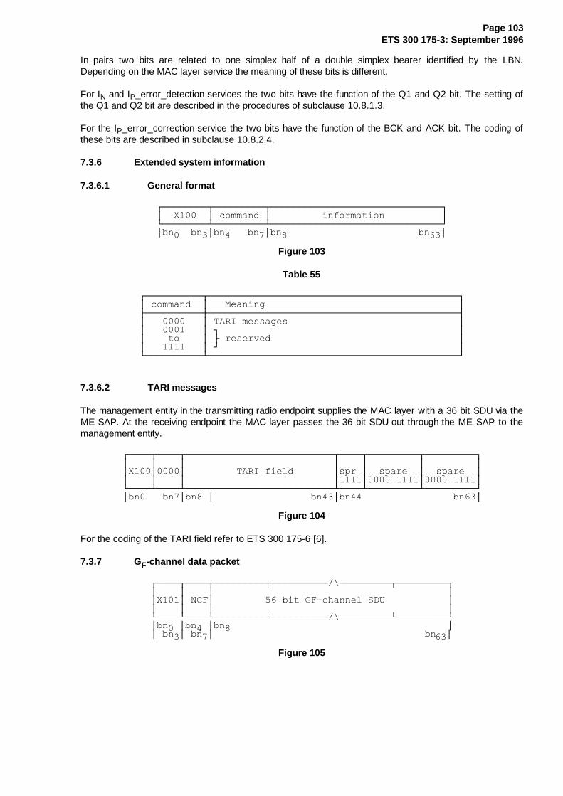
Page 103ETS 300 175-3: September 1996
In pairs two bits are related to one simplex half of a double simplex bearer identified by the LBN.Depending on the MAC layer service the meaning of these bits is different.
For IN and IP_error_detection services the two bits have the function of the Q1 and Q2 bit. The setting ofthe Q1 and Q2 bit are described in the procedures of subclause 10.8.1.3.
For the IP_error_correction service the two bits have the function of the BCK and ACK bit. The coding ofthese bits are described in subclause 10.8.2.4.
7.3.6 Extended system information
7.3.6.1 General format
¸¶¶¶¶¶¶¶¶¾¶¶¶¶¶¶¶¶¶¾¶¶¶¶¶¶¶¶¶¶¶¶¶¶¶¶¶¶¶¶¶¶¶¶¶¶¶¶¶¶¹·��;�����·�FRPPDQG�·���������LQIRUPDWLRQ����������·º¶¶¶¶¶¶¶¶¿¶¶¶¶¶¶¶¶¶¿¶¶¶¶¶¶¶¶¶¶¶¶¶¶¶¶¶¶¶¶¶¶¶¶¶¶¶¶¶¶»·EQ���EQ�·EQ����EQ�·EQ������������������������EQ��·
Figure 103
Table 55
¸¶¶¶¶¶¶¶¶¶¶¾¶¶¶¶¶¶¶¶¶¶¶¶¶¶¶¶¶¶¶¶¶¶¶¶¶¶¶¶¶¶¶¶¶¶¶¶¶¶¶¶¶¶¶¶¹·�FRPPDQG��·���0HDQLQJ����������������������������������·¼¶¶¶¶¶¶¶¶¶¶À¶¶¶¶¶¶¶¶¶¶¶¶¶¶¶¶¶¶¶¶¶¶¶¶¶¶¶¶¶¶¶¶¶¶¶¶¶¶¶¶¶¶¶¶½·����������·�7$5,�PHVVDJHV������������������������������··����������·�¹������������������������������������������··����WR����·�¼�UHVHUYHG���������������������������������··����������·�»������������������������������������������·º¶¶¶¶¶¶¶¶¶¶¿¶¶¶¶¶¶¶¶¶¶¶¶¶¶¶¶¶¶¶¶¶¶¶¶¶¶¶¶¶¶¶¶¶¶¶¶¶¶¶¶¶¶¶¶»
7.3.6.2 TARI messages
The management entity in the transmitting radio endpoint supplies the MAC layer with a 36 bit SDU via theME SAP. At the receiving endpoint the MAC layer passes the 36 bit SDU out through the ME SAP to themanagement entity.
¸¶¶¶¶¾¶¶¶¶¾¶¶¶¶¶¶¶¶¶¶¶¶¶¶¶¶¶¶¶¶¶¶¶¶¶¶¾¶¶¶¶¾¶¶¶¶¶¶¶¶¶¾¶¶¶¶¶¶¶¶¶¹·����·����·��������������������������·����·���������·���������··;���·����·���������7$5,�ILHOG�������·VSU�·��VSDUH��·��VSDUH��··����·����·��������������������������·����·���������·���������·º¶¶¶¶¿¶¶¶¶¿¶¶¶¶¶¶¶¶¶¶¶¶¶¶¶¶¶¶¶¶¶¶¶¶¶¶¿¶¶¶¶¿¶¶¶¶¶¶¶¶¶¿¶¶¶¶¶¶¶¶¶»·EQ����EQ�·EQ��·�����������������EQ��·EQ������������������EQ��·
Figure 104
For the coding of the TARI field refer to ETS 300 175-6 [6].
7.3.7 GF-channel data packet
¸¶¶¶¶¾¶¶¶¶¾¶¶¶¶¶¶¶¶¶¾¶¶¶¶¶¶¶¶¶¶�?¶¶¶¶¶¶¶¶¶¾¶¶¶¶¶¶¶¶¶¹·����·����·�����������������������������������������··;���·�1&)·������������ELW�*)�FKDQQHO�6'8�����������··����·����·�����������������������������������������·º¶¶¶¶¿¶¶¶¶¿¶¶¶¶¶¶¶¶¶¿¶¶¶¶¶¶¶¶¶¶�?¶¶¶¶¶¶¶¶¶¿¶¶¶¶¶¶¶¶¶»·EQ��·EQ��·EQ���������������������������������������··�EQ�·�EQ�·�������������������������������������EQ��·
Figure 105

Page 104ETS 300 175-3: September 1996
Table 56
¸¶¶¶¶¶¶¾¶¶¶¶¶¶¶¶¶¶¶¶¶¶¶¶¶¶¶¶¶¶¶¶¶¶¶¶¶¶¶¶¶¶¶¶¶¶¹·�1&)��·�0HDQLQJ������������������������������·¼¶¶¶¶¶¶À¶¶¶¶¶¶¶¶¶¶¶¶¶¶¶¶¶¶¶¶¶¶¶¶¶¶¶¶¶¶¶¶¶¶¶¶¶¶½·������·�QR�&)�GDWD�LQ�WKH�%�ILHOG������������··������·�RQH�%�VXEILHOG�FRQWDLQV�&)�GDWD������··������·�WZR�%�VXEILHOGV�FRQWDLQ�&)�GDWD������··������·�WKUHH�%�VXEILHOGV�FRQWDLQ�&)�GDWD����··������·�IRXU�%�VXEILHOGV�FRQWDLQ�&)�GDWD�����··������·�ILYH�%�VXEILHOGV�FRQWDLQ�&)�GDWD�����··������·�VL[�%�VXEILHOGV�FRQWDLQ�&)�GDWD������··������·�VHYHQ�%�VXEILHOGV�FRQWDLQ�&)�GDWD����··������·�HLJKW�%�VXEILHOGV�FRQWDLQ�&)�GDWD����··������·�QLQH�%�VXEILHOGV�FRQWDLQ�&)�GDWD�����··������·�¹������������������������������������··�WR���·�¼�UHVHUYHG���������������������������··������·�»������������������������������������·º¶¶¶¶¶¶¿¶¶¶¶¶¶¶¶¶¶¶¶¶¶¶¶¶¶¶¶¶¶¶¶¶¶¶¶¶¶¶¶¶¶¶¶¶¶»
7.3.8 Escape
¸¶¶¶¶¾¶¶¶¶¾¶¶¶¶¶¶¶¶¶¾¶¶¶¶¶¶¶¶¶¶�?¶¶¶¶¶¶¶¶¶¾¶¶¶¶¶¶¶¶¶¹·����·����������������������������������������������··;���·�����������HVFDSH�LQIRUPDWLRQ�����������������··����·����������������������������������������������·º¶¶¶¶¿¶¶¶¶¿¶¶¶¶¶¶¶¶¶¿¶¶¶¶¶¶¶¶¶¶�?¶¶¶¶¶¶¶¶¶¿¶¶¶¶¶¶¶¶¶»·EQ��·EQ��������������������������������������������··�EQ�·������������������������������������������EQ��·
Figure 106
Any DECT equipment may transmit an escape message.
The content of the escape information field (bn4 to bn63) is not specified. This message shall not be usedto perform a function that is specified in another part of the DECT CI standard.
8 Medium access layer primitives
The contents of clause 8 are for information only. This clause is aimed to assist in the description of layerto layer procedures.
These primitives are abstract and their concrete representations may vary from implementation toimplementation. Therefore, they shall not be considered to be a testable entity.
Four types of primitives exist, Request (req), Indicate (ind), Response (res) and Confirm (cfm). A "cfm"primitive only occurs as confirmation of an action initiated by a "req" primitive. A "res" primitive can onlyfollow a "ind" primitive. The direction of the primitives is shown in figure 107:
��������������������������?�'/&���UHT��LQG��UHV��FIP���������������������������?�������↓B���↑����↓�B��↑�B����������������������������?������↓B���↑����↓�B��↑�B���������������������//0(����?�����↓B���↑����↓�B��↑�B������������������������������?�����������������������¹������������������������������_�����������������������_���������������������UHT��¶!¶!_�����������������������_���������������������LQG���¶�¶_����������0$&����������_���������������������UHV��¶!¶!_�����������������������_���������������������FIP���¶�¶_�����������������������_������������������������������_�����������������������_������������������������������������������������������»�����������������������������������↓B���↑B����↓B��↑�B�����������������������������������↓B���↑B����↓B��↑�B�����������������������������������↓B���↑B����↓B��↑�B���������������������������3+/����UHT��LQG��UHV��FIP
Figure 107

Page 105ETS 300 175-3: September 1996
8.1 Connection oriented service primitives
Connections are identified by the MAC Connection Endpoint Identifier, MCEI.
8.1.1 Connection setup: MAC_CON {req;ind;cfm}
Parameter list:
Table 57
¸¶¶¶¶¶¶¶¶¶¶¶¶¶¶¶¶¶¶¶¶¶¶¶¶¶¶¶¶¶¶¶¶¶¶¶¶¶¶¶¶¶¶¶¶¶¶¾¶¶¶¶¶¾¶¶¶¶¶¾¶¶¶¶¶¹·�3DUDPHWHU������������������������������������·�UHT�·�LQG�·�FIP�·¼¶¶¶¶¶¶¶¶¶¶¶¶¶¶¶¶¶¶¶¶¶¶¶¶¶¶¶¶¶¶¶¶¶¶¶¶¶¶¶¶¶¶¶¶¶¶À¶¶¶¶¶À¶¶¶¶¶À¶¶¶¶¶½·�0&(,�����������������������������������������·��;��·��;��·�;���··�)0,'��QRWH�����������������������������������·��;��·��;��·�����··�30,'�����������������������������������������·��;��·��;��·�����··�FRQQHFWLRQ�KDQGRYHU�"������������������������·��;��·��;��·�����··������ROG�0&(,��QRWH��������������������������·��;��·�����·�����··�&)�UHTXLUHG�"��������������������������������·��;��·��;��·�����··����������������������������������������������·�����·�����·�����··�VORW�W\SH������������������������������������·��;��·��;��·�����··�VHUYLFH�W\SH���������������������������������·��;��·��;��·�����··������PD[�OLIHWLPH��QRWH����������������������·��2��·��;��·�����··�XS�GRZQ�VP�VV��QRWH��������������������������·��2��·��;��·�����··�FRQQHFWLRQ�W\SH������������������������������·�����·��;��·��;��··������(&1��QRWH�������������������������������·�����·��;��·��;��·¼¶¶¶¶¶¶¶¶¶¶¶¶¶¶¶¶¶¶¶¶¶¶¶¶¶¶¶¶¶¶¶¶¶¶¶¶¶¶¶¶¶¶¶¶¶¶¿¶¶¶¶¶¿¶¶¶¶¶¿¶¶¶¶¶½·�;� �SDUDPHWHU�H[LVWV�������������������������������������������··�2� �SDUDPHWHU�RSWLRQDO�����������������������������������������··��� �SDUDPHWHU�GRHV�QRW�H[LVW�LQ�WKLV�SULPLWLYH�����������������·¼¶¶¶¶¶¶¶¶¶¶¶¶¶¶¶¶¶¶¶¶¶¶¶¶¶¶¶¶¶¶¶¶¶¶¶¶¶¶¶¶¶¶¶¶¶¶¶¶¶¶¶¶¶¶¶¶¶¶¶¶¶¶¶¶½·�127(����)0,'�LV�RQO\�QHHGHG�IRU�IL[HG�SDUW�LQLWLDWHG��IDVW�����··���������VHWXS��������������������������������������������������··����������������������������������������������������������������··�127(����7KH��ROG�0&(,��SDUDPHWHU�LV�RQO\�QHHGHG�LI�FRQQHFWLRQ��··���������KDQGRYHU�� ��\HV��DQG�WKH�SUHYLRXV��FRQQHFWLRQ�W\SH�� �··����������EDVLF�������������������������������������������������··����������������������������������������������������������������··�127(����7KH��PD[LPXP�OLIHWLPH��SDUDPHWHU�RQO\�DSSOLHV�WR�WKH���··���������,3BHUURUBFRUUHFWLRQ�VHUYLFH��7KH�VHWWLQJ�RI�WKLV�������··���������SDUDPHWHU�LQ�WKH�0$&B&21�UHT�SULPLWLYH�LV�RSWLRQDO�����··���������'HIDXOW�YDOXH��L�H��DVVXPHG�ZKHQ�QRW�VHW��LV��PD[LPXP��··���������OLIHWLPH� �XQOLPLWHG�����������������������������������··����������������������������������������������������������������··�127(����7KH�VHWWLQJ�RI�WKLV�SDUDPHWHU�LQ�WKH�0$&B&21�UHT�������··���������SULPLWLYH�LV�RSWLRQDO��'HIDXOW�YDOXH�LV��VV���WKH������··���������V\PPHWULF�VLQJOH�EHDUHU�FRQQHFWLRQ���������������������··����������������������������������������������������������������··�127(����7KH��(&1��SDUDPHWHU�LV�RQO\�XVHG�LI��FRQQHFWLRQ�W\SH���··��������� ����DGYDQFHG������������������������������������������·º¶¶¶¶¶¶¶¶¶¶¶¶¶¶¶¶¶¶¶¶¶¶¶¶¶¶¶¶¶¶¶¶¶¶¶¶¶¶¶¶¶¶¶¶¶¶¶¶¶¶¶¶¶¶¶¶¶¶¶¶¶¶¶¶»
Parameter values:
MCEI = local matter;
connection handover ? = { yes, no };
old MCEI = local matter, or null;
CF required ? = { yes, no };
slot type = { double, full, half with j=0 };
service type = { IN_minimum_delay, IN_normal_delay, IP_error_detection; IP_error_correction, unknown, C-channel only };
maximum lifetime = { unlimited, 1, 2, ... , 7 };

Page 106ETS 300 175-3: September 1996
up/down/sm/ss: up = asymmetric uplink connection;down = asymmetric downlink connection;sm = symmetric multibearer connection;ss = symmetric single bearer connection;
connection type = { basic, advanced };
ECN = {0, 1, ... 15}.
8.1.2 Connection modification: MAC_MOD {req;ind;cfm}
Parameter list:
Table 58
¸¶¶¶¶¶¶¶¶¶¶¶¶¶¶¶¶¶¶¶¶¶¶¶¶¶¶¶¶¶¶¶¶¶¶¶¶¶¶¶¶¶¶¶¶¾¶¶¶¾¶¶¶¾¶¶¶¹·�3DUDPHWHU����������������������������������·UHT·LQG·FIP·¼¶¶¶¶¶¶¶¶¶¶¶¶¶¶¶¶¶¶¶¶¶¶¶¶¶¶¶¶¶¶¶¶¶¶¶¶¶¶¶¶¶¶¶¶À¶¶¶À¶¶¶À¶¶¶½·�0&(,���������������������������������������·�;�·�;�·�;�··��������������������������������������������·���·���·���··�(&1����������������������������������������·�;�·�;�·�;�··�VORW�W\SH����������������������������������·�;�·�;�·���··��������������������������������������������·���·���·���··�VHUYLFH�W\SH�������������������������������·�;�·�;�·���··������PD[�OLIHWLPH��������������������������·�;�·�;�·���··�WDUJHW�QXPEHU�RI�XSOLQN�VLPSOH[�EHDUHUV����·�;�·���·���··�WDUJHW�QXPEHU�RI�GRZQOLQN�VLPSOH[�EHDUHUV��·�;�·���·���··�PLQLPXP�DFFHSWDEOH�XSOLQN�VLPSOH[�EHDUHUV��·�;�·���·���··�PLQLPXP�DFFHSWDEOH�GRZQOLQN�VLPSOH[�EHDUHUV·�;�·���·���·¼¶¶¶¶¶¶¶¶¶¶¶¶¶¶¶¶¶¶¶¶¶¶¶¶¶¶¶¶¶¶¶¶¶¶¶¶¶¶¶¶¶¶¶¶¿¶¶¶¿¶¶¶¿¶¶¶½·�;� �SDUDPHWHU�H[LVWV�����������������������������������··��� �SDUDPHWHU�RSWLRQDO���������������������������������·º¶¶¶¶¶¶¶¶¶¶¶¶¶¶¶¶¶¶¶¶¶¶¶¶¶¶¶¶¶¶¶¶¶¶¶¶¶¶¶¶¶¶¶¶¶¶¶¶¶¶¶¶¶¶¶¶»
Parameter values are the same as MAC_CON except:
MCEI = local matter;
ECN = {0, 1, ... 15};
slot type = { double, full, half with j=0 };
service type = { IN_minimum_delay, IN_normal_delay, IP_error_detection, IP_error_correction, C-channel only };
maximum lifetime = { unlimited, 1, 2, ... , 7 };
target number of uplink simplex bearers = {1,2, ... 30};
target number of downlink simplex bearers = {1,2, ... 30};
minimum acceptable uplink simplex bearers = {1,2, ... 30};
minimum acceptable downlink simplex bearers = {1,2, ... 30}.
NOTE 1: Target number · minimum acceptable.
NOTE 2: If "slot type" = "half" then target number = minimum acceptable = 1.
NOTE 3: "Slot type" shall only be used to adjust j.
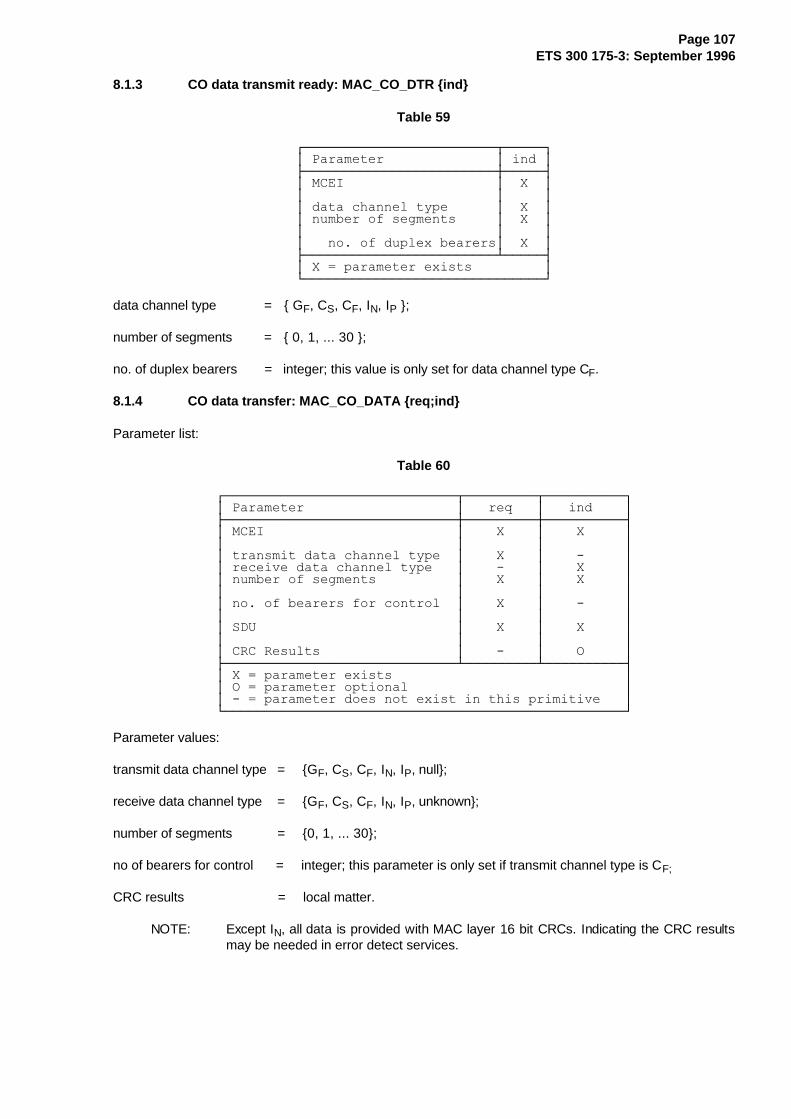
Page 107ETS 300 175-3: September 1996
8.1.3 CO data transmit ready: MAC_CO_DTR {ind}
Table 59
¸¶¶¶¶¶¶¶¶¶¶¶¶¶¶¶¶¶¶¶¶¶¶¶¶¾¶¶¶¶¶¹·�3DUDPHWHU��������������·�LQG�·¼¶¶¶¶¶¶¶¶¶¶¶¶¶¶¶¶¶¶¶¶¶¶¶¶À¶¶¶¶¶½·�0&(,�������������������·��;��··������������������������·�����··�GDWD�FKDQQHO�W\SH������·��;��··�QXPEHU�RI�VHJPHQWV�����·��;��··������������������������·�����··���QR��RI�GXSOH[�EHDUHUV·��;��·¼¶¶¶¶¶¶¶¶¶¶¶¶¶¶¶¶¶¶¶¶¶¶¶¶¿¶¶¶¶¶½·�;� �SDUDPHWHU�H[LVWV���������·º¶¶¶¶¶¶¶¶¶¶¶¶¶¶¶¶¶¶¶¶¶¶¶¶¶¶¶¶¶¶»
data channel type = { GF, CS, CF, IN, IP };
number of segments = { 0, 1, ... 30 };
no. of duplex bearers = integer; this value is only set for data channel type CF.
8.1.4 CO data transfer: MAC_CO_DATA {req;ind}
Parameter list:
Table 60
¸¶¶¶¶¶¶¶¶¶¶¶¶¶¶¶¶¶¶¶¶¶¶¶¶¶¶¶¶¶¾¶¶¶¶¶¶¶¶¶¾¶¶¶¶¶¶¶¶¶¶¹·�3DUDPHWHU�������������������·���UHT���·���LQG����·¼¶¶¶¶¶¶¶¶¶¶¶¶¶¶¶¶¶¶¶¶¶¶¶¶¶¶¶¶¶À¶¶¶¶¶¶¶¶¶À¶¶¶¶¶¶¶¶¶¶½·�0&(,������������������������·����;����·����;�����··�����������������������������·���������·����������··�WUDQVPLW�GDWD�FKDQQHO�W\SH��·����;����·����������··�UHFHLYH�GDWD�FKDQQHO�W\SH���·���������·����;�����··�QXPEHU�RI�VHJPHQWV����������·����;����·����;�����··�����������������������������·���������·����������··�QR��RI�EHDUHUV�IRU�FRQWURO��·����;����·����������··�����������������������������·���������·����������··�6'8�������������������������·����;����·����;�����··�����������������������������·���������·����������··�&5&�5HVXOWV�����������������·���������·����2�����·¼¶¶¶¶¶¶¶¶¶¶¶¶¶¶¶¶¶¶¶¶¶¶¶¶¶¶¶¶¶¿¶¶¶¶¶¶¶¶¶¿¶¶¶¶¶¶¶¶¶¶½·�;� �SDUDPHWHU�H[LVWV�����������������������������··�2� �SDUDPHWHU�RSWLRQDO���������������������������··��� �SDUDPHWHU�GRHV�QRW�H[LVW�LQ�WKLV�SULPLWLYH���·º¶¶¶¶¶¶¶¶¶¶¶¶¶¶¶¶¶¶¶¶¶¶¶¶¶¶¶¶¶¶¶¶¶¶¶¶¶¶¶¶¶¶¶¶¶¶¶¶¶¶»
Parameter values:
transmit data channel type = {GF, CS, CF, IN, IP, null};
receive data channel type = {GF, CS, CF, IN, IP, unknown};
number of segments = {0, 1, ... 30};
no of bearers for control = integer; this parameter is only set if transmit channel type is CF;
CRC results = local matter.
NOTE: Except IN, all data is provided with MAC layer 16 bit CRCs. Indicating the CRC resultsmay be needed in error detect services.
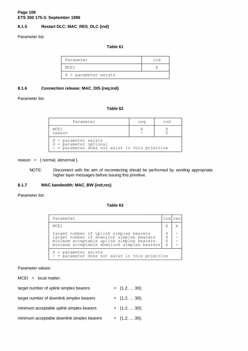
Page 108ETS 300 175-3: September 1996
8.1.5 Restart DLC: MAC_RES_DLC {ind}
Parameter list:
Table 61
¸¶¶¶¶¶¶¶¶¶¶¶¶¶¶¶¶¶¶¶¶¶¶¶¶¶¶¶¶¶¶¶¾¶¶¶¶¶¶¶¶¶¶¹·�3DUDPHWHU���������������������·����LQG���·¼¶¶¶¶¶¶¶¶¶¶¶¶¶¶¶¶¶¶¶¶¶¶¶¶¶¶¶¶¶¶¶À¶¶¶¶¶¶¶¶¶¶½·�0&(,��������������������������·�����;����·¼¶¶¶¶¶¶¶¶¶¶¶¶¶¶¶¶¶¶¶¶¶¶¶¶¶¶¶¶¶¶¶¿¶¶¶¶¶¶¶¶¶¶½·�;� �SDUDPHWHU�H[LVWV���������������������·º¶¶¶¶¶¶¶¶¶¶¶¶¶¶¶¶¶¶¶¶¶¶¶¶¶¶¶¶¶¶¶¶¶¶¶¶¶¶¶¶¶¶»
8.1.6 Connection release: MAC_DIS {req;ind}
Parameter list:
Table 62
¸¶¶¶¶¶¶¶¶¶¶¶¶¶¶¶¶¶¶¶¶¶¶¶¶¶¶¶¶¶¶¶¾¶¶¶¶¶¶¶¶¶¾¶¶¶¶¶¶¶¶¶¶¹·���������3DUDPHWHU�������������·���UHT���·���LQG����·¼¶¶¶¶¶¶¶¶¶¶¶¶¶¶¶¶¶¶¶¶¶¶¶¶¶¶¶¶¶¶¶À¶¶¶¶¶¶¶¶¶À¶¶¶¶¶¶¶¶¶¶½·�0&(,��������������������������·����;����·����;�����··�UHDVRQ������������������������·���������·����2�����·¼¶¶¶¶¶¶¶¶¶¶¶¶¶¶¶¶¶¶¶¶¶¶¶¶¶¶¶¶¶¶¶¿¶¶¶¶¶¶¶¶¶¿¶¶¶¶¶¶¶¶¶¶½·�;� �SDUDPHWHU�H[LVWV�������������������������������··�2� �SDUDPHWHU�RSWLRQDO�����������������������������··��� �SDUDPHWHU�GRHV�QRW�H[LVW�LQ�WKLV�SULPLWLYH�����·º¶¶¶¶¶¶¶¶¶¶¶¶¶¶¶¶¶¶¶¶¶¶¶¶¶¶¶¶¶¶¶¶¶¶¶¶¶¶¶¶¶¶¶¶¶¶¶¶¶¶¶¶»
reason = { normal, abnormal }.
NOTE: Disconnect with the aim of reconnecting should be performed by sending appropriatehigher layer messages before issuing this primitive.
8.1.7 MAC bandwidth: MAC_BW {ind;res}
Parameter list:
Table 63
¸¶¶¶¶¶¶¶¶¶¶¶¶¶¶¶¶¶¶¶¶¶¶¶¶¶¶¶¶¶¶¶¶¶¶¶¶¶¶¶¶¶¶¶¶¾¶¶¶¾¶¶¶¹·�3DUDPHWHU����������������������������������·LQG·UHV·¼¶¶¶¶¶¶¶¶¶¶¶¶¶¶¶¶¶¶¶¶¶¶¶¶¶¶¶¶¶¶¶¶¶¶¶¶¶¶¶¶¶¶¶¶À¶¶¶À¶¶¶½·�0&(,���������������������������������������·�;�·�;�··��������������������������������������������·���·���··�WDUJHW�QXPEHU�RI�XSOLQN�VLPSOH[�EHDUHUV����·�;�·���··�WDUJHW�QXPEHU�RI�GRZQOLQN�VLPSOH[�EHDUHUV��·�;�·���··�PLQLPXP�DFFHSWDEOH�XSOLQN�VLPSOH[�EHDUHUV��·�;�·���··�PLQLPXP�DFFHSWDEOH�GRZQOLQN�VLPSOH[�EHDUHUV·�;�·���·¼¶¶¶¶¶¶¶¶¶¶¶¶¶¶¶¶¶¶¶¶¶¶¶¶¶¶¶¶¶¶¶¶¶¶¶¶¶¶¶¶¶¶¶¶¿¶¶¶¿¶¶¶½·�;� �SDUDPHWHU�H[LVWV�������������������������������··��� �SDUDPHWHU�GRHV�QRW�H[LVW�LQ�WKLV�SULPLWLYH�����·º¶¶¶¶¶¶¶¶¶¶¶¶¶¶¶¶¶¶¶¶¶¶¶¶¶¶¶¶¶¶¶¶¶¶¶¶¶¶¶¶¶¶¶¶¶¶¶¶¶¶¶¶»
Parameter values:
MCEI = local matter;
target number of uplink simplex bearers = {1,2, ... 30};
target number of downlink simplex bearers = {1,2, ... 30};
minimum acceptable uplink simplex bearers = {1,2, ... 30};
minimum acceptable downlink simplex bearers = {1,2, ... 30}.
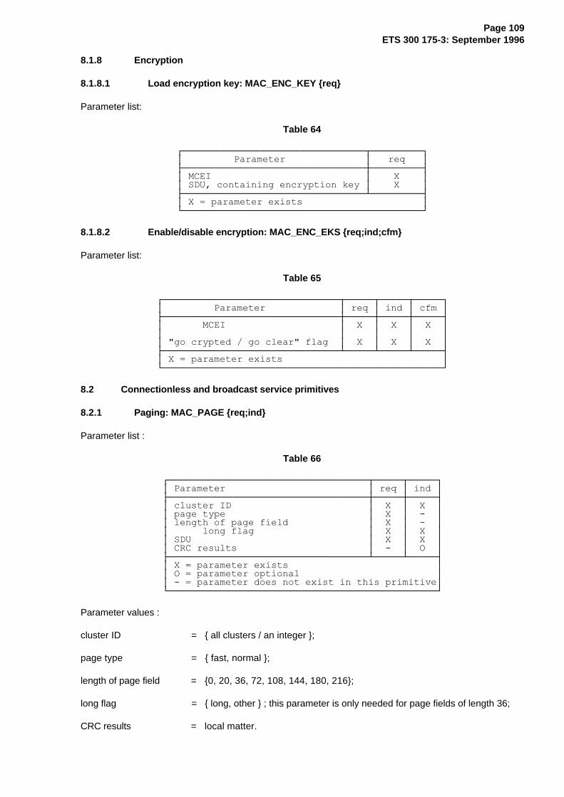
Page 109ETS 300 175-3: September 1996
8.1.8 Encryption
8.1.8.1 Load encryption key: MAC_ENC_KEY {req}
Parameter list:
Table 64
¸¶¶¶¶¶¶¶¶¶¶¶¶¶¶¶¶¶¶¶¶¶¶¶¶¶¶¶¶¶¶¶¶¾¶¶¶¶¶¶¶¶¶¹·���������3DUDPHWHU��������������·���UHT���·¼¶¶¶¶¶¶¶¶¶¶¶¶¶¶¶¶¶¶¶¶¶¶¶¶¶¶¶¶¶¶¶¶À¶¶¶¶¶¶¶¶¶½·�0&(,���������������������������·����;����··�6'8��FRQWDLQLQJ�HQFU\SWLRQ�NH\�·����;����·¼¶¶¶¶¶¶¶¶¶¶¶¶¶¶¶¶¶¶¶¶¶¶¶¶¶¶¶¶¶¶¶¶¿¶¶¶¶¶¶¶¶¶½·�;� �SDUDPHWHU�H[LVWV���������������������·º¶¶¶¶¶¶¶¶¶¶¶¶¶¶¶¶¶¶¶¶¶¶¶¶¶¶¶¶¶¶¶¶¶¶¶¶¶¶¶¶¶¶»
8.1.8.2 Enable/disable encryption: MAC_ENC_EKS {req;ind;cfm}
Parameter list:
Table 65
¸¶¶¶¶¶¶¶¶¶¶¶¶¶¶¶¶¶¶¶¶¶¶¶¶¶¶¶¶¶¶¶¾¶¶¶¶¶¾¶¶¶¶¶¾¶¶¶¶¶¹·���������3DUDPHWHU�������������·�UHT�·�LQG�·�FIP�·¼¶¶¶¶¶¶¶¶¶¶¶¶¶¶¶¶¶¶¶¶¶¶¶¶¶¶¶¶¶¶¶À¶¶¶¶¶À¶¶¶¶¶À¶¶¶¶¶½·�������0&(,��������������������·��;��·��;��·��;��··�������������������������������·�����·�����·�����··��JR�FU\SWHG���JR�FOHDU��IODJ��·��;��·��;��·��;��·¼¶¶¶¶¶¶¶¶¶¶¶¶¶¶¶¶¶¶¶¶¶¶¶¶¶¶¶¶¶¶¶¿¶¶¶¶¶¿¶¶¶¶¶¿¶¶¶¶¶½·�;� �SDUDPHWHU�H[LVWV����������������������������·º¶¶¶¶¶¶¶¶¶¶¶¶¶¶¶¶¶¶¶¶¶¶¶¶¶¶¶¶¶¶¶¶¶¶¶¶¶¶¶¶¶¶¶¶¶¶¶¶¶»
8.2 Connectionless and broadcast service primitives
8.2.1 Paging: MAC_PAGE {req;ind}
Parameter list :
Table 66
¸¶¶¶¶¶¶¶¶¶¶¶¶¶¶¶¶¶¶¶¶¶¶¶¶¶¶¶¶¶¶¶¶¶¶¶¾¶¶¶¶¶¾¶¶¶¶¶¹·�3DUDPHWHU�������������������������·�UHT�·�LQG�·¼¶¶¶¶¶¶¶¶¶¶¶¶¶¶¶¶¶¶¶¶¶¶¶¶¶¶¶¶¶¶¶¶¶¶¶À¶¶¶¶¶À¶¶¶¶¶½·�FOXVWHU�,'������������������������·��;��·��;��··�SDJH�W\SH�������������������������·��;��·�����··�OHQJWK�RI�SDJH�ILHOG��������������·��;��·�����··������ORQJ�IODJ��������������������·��;��·��;��··�6'8�������������������������������·��;��·��;��··�&5&�UHVXOWV�����������������������·�����·��2��·¼¶¶¶¶¶¶¶¶¶¶¶¶¶¶¶¶¶¶¶¶¶¶¶¶¶¶¶¶¶¶¶¶¶¶¶¿¶¶¶¶¶¿¶¶¶¶¶½·�;� �SDUDPHWHU�H[LVWV��������������������������··�2� �SDUDPHWHU�RSWLRQDO������������������������··��� �SDUDPHWHU�GRHV�QRW�H[LVW�LQ�WKLV�SULPLWLYH·º¶¶¶¶¶¶¶¶¶¶¶¶¶¶¶¶¶¶¶¶¶¶¶¶¶¶¶¶¶¶¶¶¶¶¶¶¶¶¶¶¶¶¶¶¶¶¶»
Parameter values :
cluster ID = { all clusters / an integer };
page type = { fast, normal };
length of page field = {0, 20, 36, 72, 108, 144, 180, 216};
long flag = { long, other } ; this parameter is only needed for page fields of length 36;
CRC results = local matter.
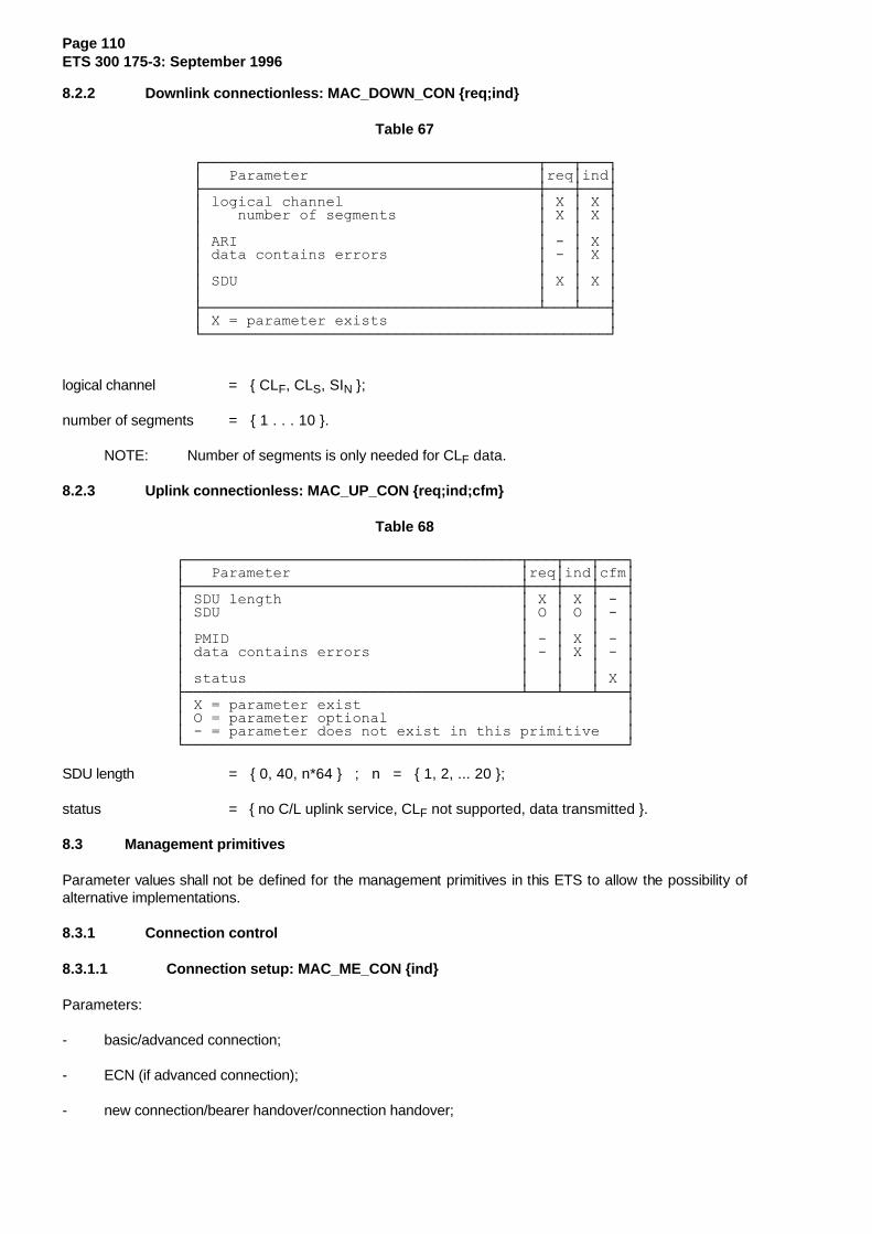
Page 110ETS 300 175-3: September 1996
8.2.2 Downlink connectionless: MAC_DOWN_CON {req;ind}
Table 67
¸¶¶¶¶¶¶¶¶¶¶¶¶¶¶¶¶¶¶¶¶¶¶¶¶¶¶¶¶¶¶¶¶¶¶¶¶¶¶¾¶¶¶¾¶¶¶¹·���3DUDPHWHU��������������������������·UHT·LQG·¼¶¶¶¶¶¶¶¶¶¶¶¶¶¶¶¶¶¶¶¶¶¶¶¶¶¶¶¶¶¶¶¶¶¶¶¶¶¶À¶¶¶À¶¶¶½·�ORJLFDO�FKDQQHO����������������������·�;�·�;�··����QXPEHU�RI�VHJPHQWV����������������·�;�·�;�··��������������������������������������·���·���··�$5,����������������������������������·���·�;�··�GDWD�FRQWDLQV�HUURUV�����������������·���·�;�··��������������������������������������·���·���··�6'8����������������������������������·�;�·�;�··��������������������������������������·���·���·¼¶¶¶¶¶¶¶¶¶¶¶¶¶¶¶¶¶¶¶¶¶¶¶¶¶¶¶¶¶¶¶¶¶¶¶¶¶¶¿¶¶¶¿¶¶¶½·�;� �SDUDPHWHU�H[LVWV�������������������������·º¶¶¶¶¶¶¶¶¶¶¶¶¶¶¶¶¶¶¶¶¶¶¶¶¶¶¶¶¶¶¶¶¶¶¶¶¶¶¶¶¶¶¶¶¶¶»
logical channel = { CLF, CLS, SIN };
number of segments = { 1 . . . 10 }.
NOTE: Number of segments is only needed for CLF data.
8.2.3 Uplink connectionless: MAC_UP_CON {req;ind;cfm}
Table 68
¸¶¶¶¶¶¶¶¶¶¶¶¶¶¶¶¶¶¶¶¶¶¶¶¶¶¶¶¶¶¶¶¶¶¶¶¶¶¶¾¶¶¶¾¶¶¶¾¶¶¶¹·���3DUDPHWHU��������������������������·UHT·LQG·FIP·¼¶¶¶¶¶¶¶¶¶¶¶¶¶¶¶¶¶¶¶¶¶¶¶¶¶¶¶¶¶¶¶¶¶¶¶¶¶¶À¶¶¶À¶¶¶À¶¶¶½·�6'8�OHQJWK���������������������������·�;�·�;�·���··�6'8����������������������������������·�2�·�2�·���··��������������������������������������·���·���·���··�30,'���������������������������������·���·�;�·���··�GDWD�FRQWDLQV�HUURUV�����������������·���·�;�·���··��������������������������������������·���·���·���··�VWDWXV�������������������������������·���·���·�;�·¼¶¶¶¶¶¶¶¶¶¶¶¶¶¶¶¶¶¶¶¶¶¶¶¶¶¶¶¶¶¶¶¶¶¶¶¶¶¶¿¶¶¶¿¶¶¶¿¶¶¶½·�;� �SDUDPHWHU�H[LVW������������������������������··�2� �SDUDPHWHU�RSWLRQDO���������������������������··��� �SDUDPHWHU�GRHV�QRW�H[LVW�LQ�WKLV�SULPLWLYH���·º¶¶¶¶¶¶¶¶¶¶¶¶¶¶¶¶¶¶¶¶¶¶¶¶¶¶¶¶¶¶¶¶¶¶¶¶¶¶¶¶¶¶¶¶¶¶¶¶¶¶»
SDU length = { 0, 40, n*64 } ; n = { 1, 2, ... 20 };
status = { no C/L uplink service, CLF not supported, data transmitted }.
8.3 Management primitives
Parameter values shall not be defined for the management primitives in this ETS to allow the possibility ofalternative implementations.
8.3.1 Connection control
8.3.1.1 Connection setup: MAC_ME_CON {ind}
Parameters:
- basic/advanced connection;
- ECN (if advanced connection);
- new connection/bearer handover/connection handover;
Page 111ETS 300 175-3: September 1996
- old MCEI (if connection handover).
8.3.1.2 Connection setup allowed: MAC_ME_CON_ALL {req}
Parameters:
- forbid/allow flag;
- forbid reason (i.e. asked for basic, can retry with advanced);
- ECN;
- new MBC required;
- MCEI.
8.3.1.3 Bearer release: MAC_ME_REL {req}
This primitive is used by the LLME to release a bearer due to not finding an MBC on handover.
8.3.1.4 MBC release report: MAC_ME_REL_REP {ind}
Parameter:
- ECN.
8.3.2 System information and identities
8.3.2.1 FP infor mation preloading: MAC_ME_RFP_PRELOAD {req}
Parameters:
- PARI;
- RPN;
- SARI;
- fixed part capabilities;
- multiframe number.
8.3.2.2 PT information preloading: MAC_ME_PT_PRELOAD {req}
Parameters:
- assigned individual TPUI;
- assigned/default flag.
8.3.2.3 System information output: MAC_ME_INFO {ind;res}
Parameters:
- PARI;
- RPN;
- SARI;
Page 112ETS 300 175-3: September 1996
- fixed part capabilities;
- multiframe number.
8.3.2.4 Extended system info: MAC_ME_EXT.{req;ind;res;cfm}
Parameters:
- FMID;
- PMID;
- SDU.
8.3.3 Channel map: MAC_ME_CHANMAP {ind;res}
Parameters:
- strongest channels;
- Quietest/free channels.
8.3.4 Status reports: MAC_ME_STATUS {req;ind;res;cfm}
Parameters:
- call status;
- slot drift/slot theft (X-field) report;
- CRC report (retransmission report);
- timer status;
- handover required;
- diversity switch required.
8.3.5 Error reports: MAC_ME_ERROR {ind;res}
Parameters:
- service overload;
- call failure.
8.4 Flow control
8.4.1 MA SAP flow control
Transmitter: the BMC of an FT may accept MAC_PAGE-req primitives. According to the paging type(fast or normal, see subclause 9.1.3.1), the SDU length, and the T-Mux algorithm the BMC will distributethe P-channel information to all TBCs, CBCs and DBCs of a cluster. If the BMC cannot distribute the SDUcontained in the MAC_PAGE-req primitive, that SDU is discarded and nothing is returned to the higherlayers.
Receiver: the BMC in a PT may receive paging messages from any bearer. If BS-channel messages werereceived in one TDMA frame the BMC should send at least one of these messages with a MAC_PAGE-indprimitive to the DLC.
Page 113ETS 300 175-3: September 1996
8.4.2 MB SAP flow control
The flow control of SIN, CLS and CLF-channel data depends on the transmission direction and theconnectionless service. Flow control is described separately for downlink and uplink directions in thecorresponding procedures in subclauses 9.1.2 and 9.2 respectively.
8.4.3 MC SAP flow control
The MBC shall request the DLC for all data to be transmitted from the CS, CF, GF, IN and IP-channel. Withthe MAC_CO_DTR-ind primitive the MBC may request for segments of several channels or selectively forsegments of only one channel. The DLC responds by issuing one or several MAC_CO_DATA-reqprimitives to the MAC. A MAC_CO_DATA primitive shall carry data segments from only one logical(sub)channel. Data is delivered from the MAC to the DLC with the MAC_CO_DATA-ind primitive.
The following primitive flow shall be provided on the transmitting side:
a) CS and CF-channels: before an ARQ window starts (see subclause 10.8.1) the MAC shall requestwith MAC_CO_DTR-ind primitives for the maximum number of allowed higher layer controlsegments (CS and CF-channel data). By requesting CF segments the MAC indicates the number ofestablished duplex bearers. The DLC shall respond with MAC_CO_DATA-req primitives. Theseprimitives shall contain at most the indicated number of CS and CF segments, and for data type CF,the number of duplex bearers allowed to carry higher layer control.
NOTE 1: The number of allowed CS or CF segments indicated with the MAC_CO_DTR-indprimitive may be zero, e.g. when retransmissions are needed.
If no CF-channel is provided the number of acceptable CF segments in the MAC_CO_DTR-indprimitive and the number of allowed duplex bearers for higher layer control in theMAC_CO_DATA-req primitive shall always be zero.
The CF data shall always be transmitted on the allowed number of duplex bearers indicated with theMAC_CO_DATA-req primitive. This rule is also applied for retransmissions of CF data. The MACshall only retransmit the CF data on the number of bearers specified by the DLC, a value "0"disables all retransmissions.
A MAC_CO_DATA-ind primitive may allow the DLC to issue one or more CF segments. The DLCmay respond with a MAC_CO_DATA-req primitive for CF data that reserves some bearers forhigher layer control but the primitive itself does not contain a SDU (i.e. number of CF segments = 0).The number of reserved bearers shall not be used for I-channel data. If no or not sufficientGF-channel data is available (see item d)) the MAC shall fill the remaining segments (see item e)).
b) IN_normal_delay and I P: before a TDMA half frame starts the MAC shall request with aMAC_CO_DTR-ind primitive for all new I-channel data segments which can be transmitted in thisTDMA half frame. The DLC shall reply with a MAC_CO_DATA-req primitive. This primitive shallcontain the requested number of I-channel segments for the IN_normal_delay service. ForIP services the number of delivered IP segments shall not exceed the number indicated in theMAC_CO_DTR-ind primitive. If a TDMA half frame is the beginning half frame of an ARQ window,the I-channel request shall follow the C-channel request.
If two bearers with the same LBN are maintained during bearer handover, I-channel data shall beduplicated on both bearers, the new and the old bearer.
c) IN_minimum_delay: just before the transmission of a bearer carrying IN data in aIN_minimum_delay service starts the MAC request with a MAC_CO_DTR-ind primitive this segment.The DLC shall respond with a MAC_CO_DATA-req primitive and deliver a IN segment.If two bearers with the same LBN are maintained during bearer handover, I-channel data may bedifferent on both bearers. The MAC shall ask for data for the two bearers using two independentprimitives. See annex H for information regarding seamless handover operation.

Page 114ETS 300 175-3: September 1996
d) GF-channel: if the GF-channel is used (IP service) and capacity is available for GF segments, theMAC request just before the transmission starts with a MAC_CO_DTR-ind primitive and indicatesthe maximum number of acceptable GF segments. The DLC may respond with aMAC_CO_DATA-req primitive and deliver at most the indicated number of segments. Capacity canbe available on bearers carrying some higher layer control, extended MAC control or on bearerswhich are not used to carry either CF or IP data.
e) Filling: if the DLC delivers insufficient control segments for a particular bearer, the MAC shall fill theremaining segments.
NOTE 2: If no control segments are delivered by the DLC, the MAC shall fill all segments.
NOTE 3: IN mode filling is performed by the DLC.
The following primitive flow shall be provided on the receiving end:
a) if the A-field CRC fails, the B-field data segments are delivered with a MAC_CO_DATA-indprimitive, and are labelled as "unknown";
b) correctly received new CS and CF data segments shall be delivered with a MAC_CO_DATA-indprimitive to the DLC at TDMA half frame boundaries;
c) correctly received GF segments are delivered to the DLC immediately with a MAC_CO_DATA-indprimitive;
d) for the IP_error_correction and IN_minimum_delay services, correctly received I-channel segmentsand all B-field segments labelled as "unknown" are delivered to the DLC immediately with aMAC_CO_DATA-ind primitive;
e) for the IP_error_detection and IN_normal_delay services, Correctly received I-channel segments andsegments labelled as "unknown" are issued to the DLC with MAC_CO_DATA-ind primitives at halfframe boundaries. Sequencing shall be provided. For sequencing the "unknown" segments aretreated as I-channel segments.

Page 115ETS 300 175-3: September 1996
9 Broadcast and connectionless procedures
9.1 Downlink broadcast and connectionless procedures
This subclause describes the procedures for the continuous downlink BMC and CMC services.
9.1.1 Downlink broadcast procedure
9.1.1.1 Broadcast information
The broadcast information provides three basic services to any locked PPs:
1) access rights identifiers: (N-channel and Q-channel);
2) system information: (Q-channel);
3) paging information: (P-channel).
Access Rights Identifiers (ARIs):
Access right identifiers are broadcast in two channels. The primary access rights identifier is repeatedmost frequently using the N-channel, and shall be provided by all RFPs. The RFP may indicate theexistence of secondary access rights identities. Any SARIs are broadcast as part of the Q-channel usingthe SARI message (see subclause 7.2.3.6).
NOTE: Tertiary Access Right Identifiers (TARIs) may also exist. These are available ondemand (see subclause 9.3).
The ARIs determine if a PP can request service from the RFP, according to the rules given inETS 300 175-6 [6].
System information:
System information gives many details about the operation of the fixed part. This is a mixture of generalinformation, plus RFP specific information.
Certain system information messages are essential for PTs to lock to a system. These messages shall betransmitted by all RFPs. The contents and provisions of these messages and the maximum intervalbetween repeats are defined in subclause 7.2.3. Transmission of these messages is described insubclause 11.1.1. The PT locking procedure is defined in subclause 11.3.
Paging information:
Paging information is used to send transient information to locked PPs. The main application of this serviceis to deliver call setup messages, these messages are used to connect incoming (FP-originated) calls.
There is a fast and a normal paging mode. In normal paging mode the paging message positions within amultiframe are restricted to minimise the duty cycle of idle locked PPs. This enables idling PPs to switchoff for the other frames. However, paging message delays may occur, and the fast paging mode is definedfor cases where a higher duty cycle is acceptable and shorter delay is wanted. Fast paging is expected tobe primarily used for data terminals.
Paging procedures are defined in subclause 9.1.3.
9.1.1.2 Channel selection for downlink broadcast services
As defined in subclause 5.7.1 the continuous broadcast service shall always be available at each CSF.This service shall be provided on:
- all traffic bearers with transmissions in the direction FT to PT;
Page 116ETS 300 175-3: September 1996
- any connectionless bearer used for a downlink CMC service;
- the dummy bearer.
Channel selection to provide the downlink broadcast service shall only be applied to setup a dummybearer, and may occur if either:
1) in presence of traffic bearers neither a bearer providing a connectionless downlink service nor adummy bearer exists; or
2) the last bearer with transmissions in the direction FT to PT is released, and neither a dummy bearernor a bearer providing a connectionless downlink service exists; or
3) one dummy bearer but no traffic bearer exists and the CSF tries to install a second dummy bearer;or
4) the RFP decides to change the physical channel for a dummy bearer; or
5) the RFP receives a "change dummy bearer position" message (see subclause 7.2.5.6) and the FT'sCSF allows a change; or
NOTE: It depends on the system configuration if a CSF allows a dummy bearer change whenrequested. FTs may ignore a "change dummy bearer position" message.
6) a connectionless downlink service has finished.
Except for situation 6) above, the FT shall choose a channel according to subclause 11.4.3 with followingpreferences:
For situation 2) above: if the last bearer with transmissions in the direction FT to PT was a trafficbearer, this bearer should be converted into a dummy bearer.
For situation 5) above: the physical channel proposed in the "change dummy bearer position" messageshould be chosen if allowed (see subclause 11.4.3).
If a CSF decides to install dummy bearer(s) when a connectionless service has finished (situation 6))above, the CSF shall convert the connectionless downlink bearers to dummy bearers.
9.1.1.3 Downlink broadcast procedure description
The downlink broadcast procedure is defined by the T-MUX rule (refer to subclause 6.2.2.1). This ruledefines the distribution of the available capacity for Q, N and P-channels.
The Q-channel information depends on the system configuration. Q-channel capacity shall be split fortransmission of the different messages according to the rules defined in subclause 7.2.3.1.
The P-channel capacity shall be used as defined in subclause 9.1.3.
9.1.2 Downlink connectionless procedure
9.1.2.1 Channel selection at the RFP
If dummy bearers exist in the CSF, all dummy bearers shall be converted into connectionless bearers.
When no dummy bearer is present or when the RFP decides to change the physical channel to provide theconnectionless downlink service, the RFP shall choose a channel according to subclause 11.4.3.
BMC services may be used to announce the creation of a new downlink service.

Page 117ETS 300 175-3: September 1996
9.1.2.2 Downlink connectionless procedure description
FT procedure:
The CBC of a downlink service normally transmits continuously, i.e. in one slot every frame (refer tosubclause 5.7). The CBC supports the BMC and the CMC downlink service. Dependent on the downlinkservice (refer to subclause 5.7.2.1) the DLC may deliver CLS, CLF or SIN data with aMAC_DOWN_CON-req primitive. During SIN services the DLC shall submit one segment of SIN channeldata per frame. For CLF services the DLC may submit at most the maximum number of CLF segments thatcan be transmitted in one frame. In addition the DLC may deliver one segment of CLS data every secondframe.
CLS data is transmitted by the RFP strictly following the T-MUX rules defined in subclause 6.2.2.1. Nonumbering is applied for CLS segments. The TA bits in the A-field header may use either code for CT tails.
CLF data is positioned in the B-field according to the definition in subclause 6.2.2.3.
PT Procedure:
Predicate: The PT has a CBC installed and is receiving the FT's connectionless bearer.
NOTE: The FT's connectionless downlink transmissions can be recognised by the specialheader coding for the NT tails. In addition, the FT may use the BMC service tobroadcast the connectionless bearer position.
The PT's CMC delivers all connectionless data together with the CRC results to the DLC using theMAC_DOWN_CON-ind primitive. If the A-field was received with errors any B-field data shall be deliveredwith data type set to "unknown". The A-field tail shall be delivered as "unknown" on A-field CRC failure onlywhen received in a TDMA frame where CT tails in the downlink direction are allowed (refer tosubclause 6.2.2.1).
9.1.3 Paging broadcast procedure
In subclause 9.1.3 the following definitions shall apply:
if "length of page field" = 0, the page is "zero length";
if "length of page field" = 20, the page is "short";
if "length of page field" = 36, the page is "full" or "long"; and
if "length of page field" > 36, the page is "long".
9.1.3.1 RFP paging broadcasts
Paging messages are used to alert a PP at any location within a DECT fixed part. The BS-channel ishandled by the broadcast message controller and the broadcast controllers in every TBC, CBC, and DBC.
The BMC in each cluster shall check that the "cluster ID" parameter in the MAC_PAGE-req primitive refersto the BMC's cluster. Zero length, short, full and long pages are distinguished by their different SDU lengthand the "long" flag for SDU length 36.
All paging messages are broadcast by an RFP using the PT type tails. Within one cluster, all BS-channelinformation shall be duplicated in the PT type tails of all bearers.
The BMC shall not generate a PT type tail containing short, full, or long page information except afterhaving received a MAC_PAGE-req primitive. Zero length pages may be generated either after receiving aMAC_PAGE-req primitive with "length of page field" = 0, or by the broadcast controller in the TBC, CBC,or DBC itself. On a traffic bearer, NT type tails should usually be sent in preference to PT type tailscontaining zero length pages.

Page 118ETS 300 175-3: September 1996
No more than one zero length page shall be sent in any multiframe.
The MAC_PAGE-req primitive shall define one of two possible paging types:
- normal paging;
- fast paging.
PT type tail transmissions are only allowed in certain frames of the multiframe (refer to subclause 6.2.2.1).Fast paging may only be used to alert PPs that listen to all allowed frames for PT tails. Normal paging isapplied to alert PPs that do not listen to all of these frames. To ensure that PPs have not to listen to allallowed frames for PT tails within one multiframe but can receive all page tails of the normal paging typetransmitted in that multiframe the FT sets an extend flag in the PT tail header. Paging tails of the normaland fast paging type shall be transmitted within a multiframe according to the following rules:
Fast full and fast short paging messages and the first segment of a fast long page message may beplaced in any frame in which transmission of PT type tails is permitted, except that they shall not interruptlong pages.
NOTE 1: Higher layer functions are used to ascertain whether a PT is likely to respond to fastpaging.
Fast zero length pages shall be treated as normal, zero length pages. Normal full, normal short and normalzero length paging messages and the first segment of a normal long page message shall be restricted tothe following frames:
a) frame 0 in any multiframe sequence;
b) frame 2, only if frame 0 has the extend flag set to 1;
c) frame 4, only if frames 0, 2 have the extend flag set to 1;
d) frame 6, only if frames 0, 2, 4 have the extend flag set to 1;
e) frame 10, only if frames 0, 2, 4, 6 have the extend flag set to 1;
f) frame 12, only if frames 0, 2, 4, 6, 10 have the extend flag set to 1.
In frame 12, the extend flag shall be set to 0.
Long pages shall have the extend flag set to 0.
NOTE 2: Within one multiframe, at most one long page of the normal paging type may betransmitted, and this is the last transmitted page of the normal paging type for thatmultiframe.
Long pages are divided into segments of 36 bits and shall be transmitted in successive frames in whichPT type tails are permitted. Long pages shall not continue from frame 12 to frame 0.
Every PT tail contains a 4 bit header. One bit is the extend flag, referred to above. The other three bits inthis header indicate the length of the page. For the BS SDU length 36 two codes are used to distinguish fulland long pages. Pages longer than 36 bits make use of three codes, one indicating "the first 36 bits of along page" another "not the last 36 bits of a long page", and the other indicating "the last 36 bits of a longpage".
Short pages contain 2 bytes of MAC layer information. Zero length pages contain 20 bits of RFP identityand then 2 bytes of MAC layer information. See subclause 7.2.4 for the format of the PT messages. Thebroadcast controller in each TBC, CBC or DBC decides which type of MAC layer information is placed inthe two byte field, and the information shall be specific to that RFP.
Page 119ETS 300 175-3: September 1996
The BMC shall at least distribute full and short pages to the broadcast controllers in TBCs, CBCs andDBCs for transmission in frame 0. The BMC need not distribute pages to the broadcast controllers inTBCs, CBCs, and DBCs for transmission in frames other than frame 0.
The broadcast controller in a TBC, CBC or DBC shall transmit the PT type tail distributed to it by the BMCin the frame indicated by the BMC.
The MAC layer shall transmit an NT type tail in frame 0 at least once every T205 seconds.
The BMC shall not supply the bearers in its cluster with page messages that are older than T204multiframes, measured from the time instant when the MAC_PAGE-req primitive was received. This limitsthe lifetime of a page message in the MAC layer.
NOTE 3: This limit applies to MAC layer repeats as well as to initial transmissions.
"Zero length" and "long" pages shall be issued by a cluster's BMC to all TBCs, CBCs and DBCs not morethan once.
For FPs that do not allow PPs to enter into low duty cycle Idle_Locked mode (see subclause 11.3.3) andprovided that capacity is available and the lifetime of the page information in the MAC layer has notexpired, then "short" and "full" pages shall be issued by the BMC at least once and may be repeated atmost three times. New page messages have priority over repetitions.
For FPs that allow the PPs to enter into low duty cycle Idle_Locked mode, provided that capacity isavailable and the lifetime of the page information in the MAC layer has not expired, the BMC shall issue"short" and "full" pages for a first transmission to all TBCs, CBCs and DBCs. The BMC shall repeat thetransmission of "short" and "full" page messages in the three multiframes following the first transmission ofthe messages, provided that the MAC layer lifetime has not expired. Repeats of page messages havepriority over first transmissions of new page messages.
NOTE 4: MAC control added to short page messages (refer to subclause 7.2.4) need not be thesame for all repetitions.
NOTE 5: The FP broadcasts within the "fixed part capabilities" message (see subclause 7.2.3.4)whether or not PPs are allowed to enter the low duty cycle Idle_Locked mode.
9.1.3.2 PP paging procedures
9.1.3.2.1 PP paging detection
Idle_Locked is the normal state of a PP between calls. In this state the PP maintains synchronism with atleast one RFP by receiving regularly PT or NT type tail messages on any bearer from an RFP. Thefrequency of the reception depends on the Idle_Locked mode:
- high duty cycle Idle_Locked mode;
- normal Idle_Locked mode;
- low duty cycle Idle_Locked mode.
These modes are described in subclause 11.3.3 and define the ability to receive page messages.
9.1.3.2.2 PP paging processing
The extend flag should be used to extend normal page detection, irrespective of the CRC result (pass orfail).
Page 120ETS 300 175-3: September 1996
The various lengths of page fields shall be handled as follows:
Zero length page: a MAC_PAGE-ind primitive shall not be issued. The contents of the PT tail may beused by the portable termination.
Short and full page: the complete BS-channel SDUs should be delivered to the higher layer, irrespectiveof the CRC result (pass or fail) with a MAC_PAGE-ind primitive. For short pages the rest of theinformation in the PT tail may be used by the PT.
Long page: the complete BS-channel SDU of a long page should be delivered to the higher layer with aMAC_PAGE-ind primitive, provided that all parts of the message (see subclause 9.1.3.1) are receivedwithout error (CRC passed).
NOTE 1: The BMC in the PT may assemble a complete message from receptions on severalbearers.
NOTE 2: Bearers from different RFPs may carry different page messages, but the pagemessages are the same for all RFPs belonging to one cluster.
9.2 Uplink connectionless procedures
9.2.1 General
This procedure allows the DLC layer in a PT to send a short protected message to the DLC layer in theFT. The PT's MAC layer may use a random access technique to select when to transmit the message.
To provide protection, the PT's MAC layer adds CRCs to the higher layer data.
The connectionless uplink service consists of one or two transmissions on a selected C/L uplink bearer.For connectionless uplink services the number of transmissions from a single PT shall not exceed N203 forany period of T215 multiframes.
Segment numbering is not defined for this service.
9.2.2 Bearer selection for the connectionless uplink
The "standard capabilities" QT message shall indicate whether an FT offers the connectionless uplinkservice. If it does not provide this service, the PT shall not attempt to make connectionless uplinktransmissions. If a "connectionless uplink" service is provided, but CF messages are not supported, thePT's MAC layer shall not attempt to transmit CLF data.
When no CF-channel is supported at the FT (see "standard capabilities", subclause 7.2.3.4.2) and a PT'sMAC layer receives a MAC_UP_CON-req primitive containing CLF segments, the PT shall respond with aMAC_UP_CON-cfm primitive with the status parameter set to "CLF not supported".
For RFPs of an FP which supports the C/L uplink service (see "fixed part capabilities", subclause 7.2.3.4),the TDD pair of any dummy or C/L downlink bearer shall be considered as a C/L uplink bearer, i.e. theRFPs listen to the allocated channel in all TDMA frames.
If a dummy bearer or a connectionless downlink bearer can be found within T214 frames after receiving aMAC_UP_CON-req primitive, the PT shall use the TDD pair of this bearer. Otherwise the PT shall select achannel for the uplink service according to the procedure defined in subclause 11.4.2.
NOTE 1: An RFP may provide one dummy bearer when traffic bearers are present. If aconnectionless downlink service is needed this dummy bearer is converted to aconnectionless bearer and is the only bearer at the RFP which supports the C/Ldownlink service. RFPs may broadcast the position of a permanent broadcast orconnectionless bearer using the BMC service (PT tail).
Page 121ETS 300 175-3: September 1996
NOTE 2: At least one dummy bearer is always maintained when no traffic or connectionlessbearer for downlink transmissions exist.
A dummy bearer is marked as a short bearer (no B-field) in the BA field of the A-field header and uses thenormal identification for NT tails.
A connectionless downlink bearer is marked by using a special identification for NT tails.
9.2.3 Procedure for the connectionless uplink
9.2.3.1 Predicates
1) The PT shall be in the Idle_Locked or Active_Locked state;
2) the PT shall know of at least one bearer suitable for an uplink connectionless transmission (seesubclause 9.2.2);
3) the PT knows the FMID of a suitable RFP;
4) the PT has a CBC installed.
9.2.3.2 PT D-field construction
When the PT's MAC layer receives a MAC_UP_CON-req primitive it constructs one or two D-fields to betransmitted by its physical layer.
The A-field of the first D-field contains the "first PT transmission" TA bits; FMID; PMID; and a byteidentifying the connectionless uplink service (see subclause 7.2.5.6).
For the CLF service as many CLF segments as possible are placed in the B-field, and MAC layer CRCsare added. Segments of CLF data are positioned according to the rules of subclause 6.2.2.3.
If the SDU length is 0 (only PMID exchange) or 40 bits (CLS service), the B-field may be filled in anymanner with the BA code in the A-field header = 000, or need not even be transmitted at all with the BAcode = 111.
A second D-field shall be constructed for CLF services with 11 to 20 segments in double slot mode, with 5to 8 CLF segments in full slot mode, or with 2 CLF segments in half slot mode, and for the CLS service.
For the CLS service the TA bits in the second D-field indicate data from the CLS-channel by using either ofthe CT tail coding and place the SDU in the tail.
For the CLF services the A-field shall contain a MT tail identifying the second transmission of aconnectionless uplink service (see subclause 7.2.5.6).
9.2.3.3 PT transmission sequence
Transmission sequence of the PT's CBC depends on the channel selection criteria:
a) the selected channel is the TDD pair of a connectionless downlink or a dummy bearer;
b) the PT selected a free channel.
Page 122ETS 300 175-3: September 1996
Case a)
The transmission sequences are different for C/L uplink services using one or two transmissions:
1) One transmission:
- the PT sends the D-field in an arbitrarily chosen frame.
2) Two transmissions:
- the PT sends the first D-field in an arbitrarily chosen even numbered frame, and thesecond D-field on the same channel in the next TDMA frame.
NOTE 1: The uplink channel on the TDD pair of a dummy or C/L downlink bearer is not checkedprior to transmission.
NOTE 2: Controlled by the higher layers retransmissions of the same C/L uplink data may occur.To prevent continuous collisions (e.g. two PTs start transmission in the same TDMAframe and use the same retransmission algorithm in their higher layers), the MAC layershould choose a random delay between receiving a MAC_UP_CON-req primitive andthe beginning of the first transmission.
Case b)
- After selecting the channel (see subclause 11.4) the PT sends the first D-field in time with theprimary receiver scan of the FT;
- if the connectionless uplink service consists of two transmissions the PT sends the second D-field onthe same channel in the next TDMA frame.
9.2.3.4 FT procedure
The FT may receive a C/L uplink transmission either on the TDD half of its dummy or connectionlessdownlink bearer, or by scanning for PT first transmissions. When receiving a PT's C/L uplink transmissionmarked as "first PP transmission" (see subclause 7.1.2) with correct A-field CRC and containing the FT'sFMID, the FT shall install a CBC to process the C/L uplink service.
The FT shall decide upon the coding of the MT tail message (see subclause 7.2.5.6) whether the PT usesa single transmission uplink service or a double transmission uplink service. If a double transmission uplinkservice is in progress the FT's CBC shall receive the second transmission in the next TDMA frame on thesame connectionless uplink bearer.
If all data related to the C/L uplink service has been received correctly, i.e. with correct CRCs, the CMCissues a MAC_UP_CON-ind primitive to the DLC with the SDU containing received CLF or CLS data.
9.3 Non-continuous broadcast procedure
A-field and B-field procedures exist which allow PTs to acquire more Q-channel information and as afurther BMC service to request a new dummy bearer.
9.3.1 Request for specific Q-channel information
A PT may acquire extended system information upon request. The procedure is initiated by the PT's LLME(see subclause 11.2.1).

Page 123ETS 300 175-3: September 1996
9.3.1.1 A-field procedure
PT procedure:
The PT creates two D-fields to be transmitted by its physical layer. The B-field of both transmissions maybe filled in any manner or need not even be transmitted at all.
The A-field of the first D-field contains the "first PT transmission" TA bits, FMID, PMID, and a byteidentifying the service (extended system information; see subclause 7.2.5.6).
The A-field of the second D-field contains the MT tail TA bits and the request in the A-field tail (refer tosubclause 7.2.5.10).
The PT selects a channel according to the rules for duplex bearers (see subclause 11.4) and sends thefirst D-field in time with the primary receiver scan of the FT. The PT transmits the second D-field on thesame channel in the next TDMA frame.
The PT then listens to the TDD pair of the bearer until a reply is received or time-out expires (T206, seesubclause 11.2.2).
FT procedure:
An FT receiving an extended system information request issues the request to the LLME (seesubclause 11.2.2). If the LLME replies the FT creates two D-fields to be transmitted. The B-field of bothtransmissions may be filled in any manner or need not even be transmitted at all.
The A-field header of both transmissions use the MT tail TA bits.
The first A-field tail contains FMID, PMID, and a byte identifying the service (extended system information;see subclause 7.2.5.6).
The second A-field tail contains the FT response (refer to subclause 7.2.5.10).
The RFP selects the TDD pair of that channel on which the request was received and transmits theD-fields in two successive frames.
9.3.1.2 B-field procedure
PT procedure:
The PT creates one single D-field for the request. This D-field is marked as a "first PT transmission" in theA-field header. The A-field tail contains a special MT tail identifying the transmission as part of theextended system information service. The B-field contains the request(s) (see subclause 7.3.6).
The PT selects a free channel according to the rules for duplex bearers (see subclause 11.4.2) andtransmits the D-field in time with the primary receiver scan of the FT. The PT then scans the TDD pair ofthe bearer until a reply is received or time-out expires (T206, see subclause 11.2.2). A reply is markedwith the same MT tail as used for the request. Replies are delivered to the LLME (see subclause 11.2.1).
FT procedure:
An FT receiving a extended system information request issues the request to the LLME (seesubclause 11.2.2). If the LLME replies the FT creates one D-field with the A-field containing an MT tail.This tail identifies the D-field as part of the extended system information service (see subclause 7.2.5.6).The B-field contains the response from the LLME.
The RFP selects the TDD pair of that channel on which the request was received and transmits the D-fieldonce on this channel.

Page 124ETS 300 175-3: September 1996
9.3.2 Request for a new dummy bearer
A PT may request the continuous BMC service on a new dummy bearer. The PT, therefore, selects a freechannel and prepares one single D-field. The D-field contains an A-field with an MT tail identifying theservice (see subclause 7.2.5.6). The D-field is marked as "first PT transmission" (see subclause 7.1.2).The B-field may be filled in any manner or need not even be transmitted at all. The PT transmits the D-fieldin time with the primary receiver scan of the FT on the selected channel.
The FT may ignore the PT's request or install the dummy bearer on the TDD half of that channel on whichthe request was received. A PT shall not attempt to change the dummy bearer position at an RFP aftertwo successive unsuccessful attempts to this RFP.
10 Connection oriented service procedures
10.1 Overview
The connection oriented procedures use two peer-to-peer associations, connections and bearers. Aconnection is the association that is visible to the DLC layer, and each connection uses the services of oneor more bearers as described in subclause 5.6.
The procedures are described in the following groups:
Connection control procedures:
- connection setup (see subclause 10.2);- connection modification (see subclause 10.3);- connection release (see subclause 10.4).
Bearer control procedures:
- bearer setup (see subclause 10.5);- bearer handover (see subclause 10.6);- bearer release (see subclause 10.7).
Data transfer (see subclause 10.8):
- CRFP connection control procedures (see subclause 10.9).
The procedures are written in the style of a time sequence diagram, with the PT and FT proceduresinterlaced to represent the order of events. The steps are numbered as a single series, and the variedoutcomes are described with a series of lettered substeps (3a, 3b etc).
10.2 C/O connection setup
Connection setup is the first phase of a connection orientated MAC service and the first phase of aconnection handover. The phrase "Connection_Established" is defined to mean completion of setup at theMAC layer.
Connection setup can be originated from either side. These directions are defined as follows:
- MAC PT_originated;
- MAC FT_originated.
All setup attempts for connection handover are PT_originated.

Page 125ETS 300 175-3: September 1996
10.2.1 General
There are four connection setup processes:
- basic connection setup process, PT_originated;
- normal connection setup process, PT_originated;
- fast connection setup process, FT_originated;
- physical connection setup process, REP_originated.
The basic setup process is used to set up a basic connection. The normal and fast setup processes createadvanced connections (see subclause 5.6).
The physical setup process is used to set up a physical connection (see subclause 10.5.1.5).
10.2.2 Initiation of a basic and a normal connection setup
A basic or normal setup may be initiated by a network layer call that originates from either the PT or FT asdetailed in the following overview:
FT_originated call:
- FT higher layer sends a paging command to the PT higher layer;
- if this page is received successfully, the PT higher layer initiates a connection setup by issuing aMAC_CON-req primitive to the PT MAC layer.
PT_originated call:
- the PT higher layer initiates a connection setup by issuing a MAC_CON-req primitive to the PT MAClayer.
10.2.3 Initiation of a fast connection setup
FT_originated call only:
- the FT DLC initiates a connection setup without any prior paging by issuing a MAC_CON-reqprimitive to the MAC layer. This primitive is addressed to only one RFP and the address of the RFPshall be known in advance.
10.2.4 Connection setup procedure description
10.2.4.1 Creation of MBCs
Calling side:
A connection setup starts with the initiation process, either the DLC in the PT (basic and normal setup) orthe DLC in the FT (fast setup) issues a MAC_CON-req primitive to its MAC.
This primitive includes a MAC Connection Endpoint Identifier (MCEI) which is used to identify all furtherprimitives related to this connection.
For fast connection setup the MAC_CON-req primitive shall include the Radio fixed Part Number (RPN) toidentify the RFP to which the PT is registered, and the calling address which is the PMID. If the wantedRFP cannot be addressed by the MBC the MAC issues a MAC_DIS-ind primitive to the DLC and releasesthe MBC entity.
Page 126ETS 300 175-3: September 1996
If a connection is requested to perform a connection handover the MAC_CON-req primitive shall includethe new and the old MCEI.
In addition, the MAC_CON-req primitive shall include the necessary parameters to identify the wantedservice. After receiving a paging command the full service description is not always known by the PTs.Then the service has type "unknown".
If the MAC cannot establish a connection (e.g. an advanced connection is needed and the FT onlysupports basic connections) or the MAC does not support the wanted service (e.g. the MAC only knowsbasic connections and a data service is wanted) the MAC issues a MAC_DIS-ind primitive to the DLC andreleases the MBC ending the procedure.
The MBC asks the LLME for allowance to set up the connection between the FT (as identified by its ARI)and the PT (as identified by its PMID). If a single bearer IN_minimum_delay service is wanted and noCF-channel is required the MBC may ask to establish a basic connection, otherwise the MBC asks for anadvanced connection (see subclause 5.6). If the new connection is for connection handover the MBC alsoissues the MCEI of the old connection to the LLME.
Whenever an MBC is allowed to establish an advanced connection the LLME assigns the ExchangedConnection Number (ECN) to the MBC.
The LLME may forbid the establishment of the desired connection (e.g. there already exists a basicconnection, no further ECNs available). If a basic connection was requested by the MBC and thenprohibited by the LLME, the MBC may reattempt by asking for an advanced connection.
If it is not allowed to set up the wanted connection the MAC issues a MAC_DIS-ind primitive to the DLCindicating the reason, and releases the MBC.
If the MBC is allowed to set up the connection the MAC reports the connection type (basic or advanced)with the MAC_CON-cfm primitive to the DLC after the successful setup of the first bearer.
NOTE 1: In the case of a successful connection setup there exists a common identification forthe connection known at both, PT and FT. It consists of ARI + PMID (+ ECN) wherethe ECN only appears for advanced connections. For advanced connections thisidentification is always unique within the PT and the FT. For basic connections aduplication may occur only during connection handover.
NOTE 2: It is assumed that the PMID does not change during one connection (e.g. from anarbitrary PMID to a PMID derived from the assigned individual TPUI (seesubclause 11.7.2)).
The first task of the calling side's MBC is to invoke the creation of a new MBC at the called side. To allowthe necessary radio transmissions at least one bearer controlled by a TBC shall exist. For setting up newbearers the MBC chooses one of the bearer setup procedures. The choice depends on the requestedservice (see subclauses 10.2.4.2 and 10.2.4.3).
Higher layer control during connection setup:
At the calling side the MAC may enable transmissions of higher layer control even in the first transmission.After receiving the MAC_CON-req primitive the MAC may ask immediately for higher layer controlsegments with a MAC_CO_DTR-ind primitive (refer to subclause 8.4.3).
Called side:
On the called side a new TBC is created by receiving a "bearer_request" message including both a callingaddress and its own address (FMID and PMID) on the scanned physical channel. The message type alsocontains the information if the new bearer belongs to a basic or an advanced connection.

Page 127ETS 300 175-3: September 1996
The TBC has then to receive all necessary parameters to identify an MBC. The MBC is fully identifiedafter:
a) receiving with the "bearer_request" message either an access request or a handover request,including the calling address (FMID or PMID) and defining the connection type (advanced orbasic); and
b) for advanced connections only, receiving an ECN; and
c) for basic connections and only in case of a handover request, an indication if bearer orconnection handover is wanted.
NOTE 3: The parameters are not always known after the first received message, e.g. for setupprocedures using the advanced connection control MT message set, the conditions arefulfilled after receiving two messages, the "bearer_request" message and the"attributes_request" message (see subclause 10.5.1.2.1).
The TBC issues PMID, ARI and for an advanced connection also the ECN to the LLME and indicates thepurpose of the wanted connection (bearer/connection handover or new connection).
NOTE 4: For an FT initiated bearer setup the calling address is the FMID. But the PT has to belocked to the calling RFP and, therefore, the PT knows the FT's ARI.
The LLME can now decide:
a) to release the TBC;
b) to connect the TBC to an existing MBC; or
c) to create a new MBC for connecting the TBC.
If a new MBC is needed the LLME requests the MAC to create a new MBC and assigns a MCEI to thisMBC. The creation of a new MBC is reported to the DLC by issuing a MAC_CON-ind primitive after thefirst successful bearer setup. This primitive informs the DLC if a basic or an advanced connection is set up,and describes the wanted service type.
NOTE 5: The wanted service may be of type "unknown" at this moment.
Higher layer control during connection setup:
The called side may enable transmission of higher layer control after issuing the MAC_CON-ind primitive.The MAC has to ask for this higher layer control with a MAC_CO_DTR-ind primitive (refer tosubclause 8.4.3).
10.2.4.2 Establishment of a single bearer duplex connection of a known service type
This procedure is applied for all basic connections and for some advanced connections. Advancedconnections are established with this procedure provided that:
a) the MAC_CON-req primitive at the initiating side contained the full MAC layer service description;and
b) the connection is a single bearer connection.
For a single bearer connection the duplex bearer setup is initiated by:
a) the PT, for basic and normal connection setup;
b) the FT, for fast connection setup.

Page 128ETS 300 175-3: September 1996
With the creation of the MBC on the initiating side a connection setup timer (T200, see annex A) is started.A successful connection setup shall be completed before this timer expires. Otherwise the connectionsetup fails.
The MBC of the initiating side shall have knowledge of at least one available physical channel. The MBCshall also know the address (FMID or PMID) of the called part. The MBC creates a TBC and issues thecalled address (FMID/PMID) and the physical channel description to the new TBC. The MBC alsoindicates if the wanted bearer is used for bearer handover, connection handover or for a new MACconnection and which single bearer setup procedure has to be used. For advanced single bearerconnections the logical bearer number of the only bearer shall be set to 15 (= "1111"). The MBC issues theLBN and the ECN to the TBC.
To establish the bearer the TBC uses one of the following procedures:
a) the basic bearer setup procedure (see subclause 10.5.1.1) for a basic connection setup;
b) the PT initiated A-field advanced single bearer setup procedure (see subclause 10.5.1.2.1) or thePT initiated B-field advanced single bearer setup procedure (see subclause 10.5.1.3.1) for a normalconnection setup;
c) the FT initiated B-field advanced single bearer setup (see subclause 10.5.1.3.2) for fast connectionsetup.
At the end of a setup procedure a TBC will report to the MBC either:
- "Bearer_established" or "bearer_setup_failed", indicating the reason.
NOTE 1: At the destination side these messages only occur if a bearer setup attempt wasdetected and a new MBC was created.
If a bearer setup attempt failed the TBC is released (see bearer setup procedures). The calling MBC canreattempt with the same procedure up to N200 (see annex A) times, subject to using a new availablechannel each time and/or accessing a new RFP (see subclause 11.4.2). Each reattempt is reported to theDLC with a MAC_RES_DLC-ind primitive.
NOTE 2: This reporting of reattempts is necessary to support overlapped setup, whereby setupof the higher layers occurs at the same time as setup of the MAC layer.
Explanation: The MAC forgets acknowledged higher layer data and so this data cannot berepeated in a MAC bearer setup reattempt. The primitive, therefore, tells thehigher layers that a new connection setup was started automatically. Higherlayers shall restart their overlapped procedures, or shall release the MAC setupwith a MAC_DIS-req primitive.
If the setup attempt fails N200 + 1 times or the connection setup time-out (T200) expires, the initiatingMAC reports "setup_failure" to its DLC, using a MAC_DIS-ind primitive with the reason and releases theMBC. This event is also reported to the LLME.
At the called side it is not always possible to recognise how often setup attempts fail. Here the MBC isalways released when "bearer_setup_failed" was recognised (see single bearer setup procedures) or by atime-out (e.g. T200 or T201). The connection setup timer (T200) for a new MBC shall be started atcreation of the MBC. Release of an MBC at the called side is always reported to the LLME, and to its DLCwith a MAC_DIS-ind primitive provided that a MAC_CON-ind primitive was issued before.
NOTE 3: This condition may occur if a bearer setup was successful at the called side but failedat the calling side. Here the calling side may reattempt to setup a bearer.
An MBC assumes that a bearer setup was successful when the TBC reported "bearer_established".

Page 129ETS 300 175-3: September 1996
When the TBC at the called side reports "bearer_established" the MBC knows all necessary MACparameters for the wanted service. If the MAC does not support the wanted service it will proceed with aconnection release procedure and should indicate the reason (see subclause 10.4).
If the MAC supports the service the connection setup for a single bearer connection is completed.Immediately after the TBC reported "bearer_established" the MAC reports "connection_established" plusservice parameters with a MAC_CON-ind primitive at the called side or with a MAC_CON-cfm primitive atthe initiating side to the DLC. All following transmissions may contain valid I-channel data and the MACuses the appropriate multiplex for the wanted service.
10.2.4.3 Establishment of multi-bearer connections and connections needing servicenegotiation
Overview:
The following service negotiation procedures shall be used to establish all asymmetric connections, andshall also be used for symmetric multi-bearer connections.
The procedure shall also be applied for connections with service type "unknown".
Channel list messages shall be used for the establishment of asymmetric connections as defined insubclause 10.5.1.4. Channel list messages should be used for all multibearer connection establishment.
During a multi-bearer connection establishment, the first pilot (duplex) bearer within one connection shall beset up by the initiating side (see subclauses 10.2.2 and 10.2.3). Either of the two MBCs may be themaster for all subsequent bearer establishment in the sense that this MBC initiates all of the remainingbearer setups.
The multi-bearer connection establishment procedure starts with the setting up of one duplex bearer, the"pilot channel". This allows the service type to become known, (if it was unknown), and initial channel listmessages to be exchanged.
NOTE 1: Channel list messages and procedures are described in subclause 10.5.2.
The pilot (duplex) bearer setup is initiated by:
- the PT, for normal connection setup;
- the FT, for fast connection setup.
Procedure description:
The receipt of a MAC_CON-req primitive causes the creation of the MBC on the initiating side and thestarting of a connection setup timer (T200). A successful connection setup shall be completed before thistimer expires. Otherwise the connection setup fails and any bearers that have been set up are released.
The MBC of the initiating side shall have knowledge of at least one available physical channel. The MBCshall also know the address (FMID or PMID) of the called part. The MBC creates a TBC and issues thecalled address (FMID/PMID) and the physical channel description to the new TBC. The MBC alsoindicates if the wanted pilot bearer is used for connection handover or for a new connection. For the pilotbearer the MBC sets the logical bearer number to 15 (= "1111") and issues the LBN and the ECN to theTBC.
To establish the bearer the TBC uses one of the following procedures:
- the PT initiated A-field advanced single bearer setup procedure (see subclause 10.5.1.2.1) or thePT initiated B-field advanced single bearer setup procedure (see subclause 10.5.1.3.1) for a normalconnection setup;

Page 130ETS 300 175-3: September 1996
- the FT initiated B-field advanced single bearer setup (subclause 10.5.1.3.2) for fast connectionsetup.
At the end of a setup procedure a TBC will report to the MBC either:
- "bearer_established"; or
- "bearer_setup_failed", indicating the reason.
NOTE 2: At the destination side these messages only occur if a bearer setup attempt wasdetected and a new MBC was created.
If a bearer setup attempt failed the TBC is released (see bearer setup procedures) and the calling MBCcan reattempt with the same procedure up to N200 (see annex A) times, subject to using a new availablechannel each time and/or accessing a new RFP (see subclause 11.4.2). Each reattempt is reported to theDLC with a MAC_RES_DLC-ind primitive.
NOTE 3: This reporting of reattempts is necessary to support overlapped setup, whereby setupof the higher layers occurs at the same time as setup of the MAC layer.
Explanation: The MAC forgets acknowledged higher layer data and so this data cannot berepeated in a MAC bearer setup reattempt. The primitive, therefore, tells thehigher layers that a new connection setup was started automatically. Higherlayers shall restart their overlapped procedures, or shall release the MAC setupwith a MAC_DIS-req primitive.
If the setup attempt fails N200 + 1 times or the connection setup time-out expires (T200) the initiating MACreports "setup_failure" to the DLC, using a MAC_DIS-ind primitive with the reason set and releases theMBC. This event is also reported to the LLME.
At the called side it is not always possible to recognise how often setup attempts fail. Here the MBC isalways released when "bearer_setup_failed" was recognised (see single bearer setup procedures) or by atime-out (e.g. T200 or T201). The setup timer (T200) for a new MBC shall be started at the creation of theMBC. A release of an MBC is always reported to the LLME, and to the DLC with a MAC_DIS-ind primitiveprovided that a MAC_CON-ind primitive was issued before.
An MBC assumes that a bearer setup was successful when the TBC reported "bearer_established".
When the TBC at the called side reports "bearer_established" the called MBC may know all the necessaryMAC parameters for the wanted service. If the service is defined and the called MAC does not support thisservice it will proceed with a connection release procedure and should indicate the reason (seesubclause 10.4). Otherwise the MBC issues a MAC_CON-ind primitive to the DLC.
The MBC on the initiating side issues a MAC_CON-cfm primitive to the DLC after the TBC reported"bearer_established".
If the service is not fully defined, e.g. the service type is "unknown" or the number of bearers is undefined,the connection is in a pending state until the DLC on either side issues a MAC_MOD-req primitive that shallcontain all necessary parameters.
NOTE 4: For PT initiated calls the MAC_MOD-req primitive may be issued at the same time asthe MAC_CON-req primitive.
NOTE 5: A MAC_MOD-req primitive is needed for all multibearer connections.
The MBC at the side where the MAC_MOD-req primitive was issued shall release the connection when thewanted service is not able to be supported. Otherwise the MBC sends repeatedly the appropriateattributes and/or bandwidth request messages, until these messages are confirmed or a connectionrelease is recognised. If both messages are needed, the bandwidth request message shall not precedethe attribute request message.

Page 131ETS 300 175-3: September 1996
When negotiating the bandwidth the requesting side shall propose the wanted bandwidth. The bandwidthconfirm message, however, may contain the same minimum and target number of bearers or a reducednumber of bearers. The negotiated bandwidth is given by the numbers in the confirm message. If thebandwidths in the request and confirm message are different the MBC at the initiating side shall issue aMAC_BW-ind primitive to the DLC. When the offered bandwidth is sufficient for the service the DLC shallreply with a MAC_BW-res primitive, otherwise with MAC_DIS-req primitive. The latter case shall cause aconnection release.
MAC_MOD-ind and -cfm shall not be issued until the connection is fully established.
Now the two MBC functions have the same, complete, knowledge of the connection that is required.Further progress depends upon the service type :
- symmetric connection;
- asymmetric uplink connection; or
- asymmetric downlink connection.
10.2.4.3.1 Symmetric connection
A symmetric connection is one that offers a symmetric I-channel service to the DLC. The eventualbandwidth and service type for the direction PP to FP and FP to PP are identical. A symmetric connectionshall only use duplex bearers.
If the connection is a single bearer connection (previously of type "unknown"), this is now established andMAC_MOD-ind and MAC_MOD-cfm primitives are issued.
Otherwise this is a multibearer connection, and all following bearer set ups shall be PT initiated. The PTshall "add" duplex bearers using the A-Field advanced or B-Field single bearer setup procedures (seesubclauses 10.5.1.2.1 and 10.5.1.3.1). The channel list procedures described in subclause 10.5.2 shouldbe used to decrease the connection establishment time by negotiating changes to the receiver scanningpatterns at the receiving side.
10.2.4.3.2 Asymmetric uplink connection
An asymmetric uplink connection is one that offers an asymmetric I-channel service to the DLC. It shall usea mixture of double simplex bearers in the direction PP to FP and duplex bearers.
For all subsequent double simplex bearer setups the PT is the T-side. The double simplex setup procedureis described in subclause 10.5.1.4.
The number of duplex bearers shall be determined by the MBC in the PT, and at least one duplex bearershall be maintained at all times. The PT may add duplex bearers by using the procedures defined insubclauses 10.5.1.2.1 or 10.5.1.3.1. For setting up further duplex bearers the channel list procedures(refer to subclause 10.5.2) should be used in order to decrease the connection establishment time.
10.2.4.3.3 Asymmetric downlink connection
A asymmetric downlink connection is one that offers an asymmetric I-channel service to the DLC. It shalluse a mixture of double simplex bearers in the direction FP to PP and duplex bearers.
For all subsequent double simplex bearer setups the FT is the T-side. The double simplex setup procedureis described in subclause 10.5.1.4.
The number of duplex bearers shall be determined by the MBC in the FT, and at least one duplex bearershall be maintained at all times. The FT may add duplex bearers by using the procedures defined insubclauses 10.5.1.2.2 or 10.5.1.3.2. For setting up further duplex bearers the channel list procedures(refer to subclause 10.5.2) should be used in order to decrease the connection establishment time.
Page 132ETS 300 175-3: September 1996
10.2.4.3.4 Connection established
When the number of established bearers equals the "minimum" parameter the MBC entities shall issue theappropriate MAC_MOD primitive (ind or cfm) to report "connection_established". The MBCs shall keepattempting to obtain the "target" number of bearers until the connection setup timer (T200) expires, andmay try to obtain this number of bearers afterwards.
If the connection set up timer expires at either side before the "minimum" number of bearers areestablished, a MAC_DIS-ind primitive is issued containing "connection_establishment_failure" and allestablished bearers are released. The release of the bearers shall cause the other side to issue aMAC_DIS-ind primitive.
All transmissions following the MAC_MOD-ind or MAC_MOD-cfm primitive respectively may contain validI-channel data and the MAC shall use the appropriate multiplex for the wanted service.
10.3 C/O connection modification
The DLC on either side may initiate a connection modification of an advanced connection by issuing aMAC_MOD-req primitive.
Modifications to existing connections are only allowed to change the bandwidth, i.e. the number of requiredbearers. The transmission direction of double simplex bearers may be switched by using the fast releaseprocedure (see subclause 10.7.2.3). Switching a bearer from duplex to double simplex and vice versa isprohibited.
NOTE 1: A bandwidth change may switch a single bearer connection to a multibearer connectionand vice versa.
NOTE 2: A bandwidth change may switch an asymmetric connection to a symmetric connectionand vice versa or may change the direction of an asymmetric connection.
NOTE 3: Some bandwidth change requests may cause ambiguous situations of the MACI-channel data flow, e.g:
- the wanted minimum number of simplex bearers in one direction is above theactual number of established bearers, and, therefore, the MAC cannot providethe new service instantaneously;
- sequencing of data segments in IN_normal_delay and IP_error_detectionservices might fail during the establishment of new bearers.
NOTE 4: In multibearer connections the sequencing of I-channel data segments forIN_normal_delay and IP_error_detection services can only be guaranteed by the MAClayer if the minimum number of needed bearers equals the target number of bearers.Adding or releasing bearers during a call may cause ambiguous situations (seesubclauses 8.4.3 and 10.8.3.2).
Whenever the bandwidth change might cause ambiguity for the data service it is assumed that the sidewhich invokes the connection modification has already negotiated the modification at a higher layer. Inthese cases, the receiving DLC should ignore I-channel data delivered before receiving a MAC_MOD-indor -cfm primitive.
The MBC at the initiating side sends repeatedly the appropriate bandwidth request message (A-field orB-field) until a bandwidth confirm message is received or a connection release is recognised. Thebandwidth confirm message may contain the same minimum and target number of bearers or reducednumber of bearers. The negotiated bandwidth is given by the numbers in the confirm message. If thebandwidths in the request and confirm message are different the MBC at the initiating side shall issue aMAC_BW-ind primitive to the DLC. When the offered bandwidth is sufficient for the service, the DLC shallreply with a MAC_BW-res primitive, otherwise with a MAC_DIS-req primitive.

Page 133ETS 300 175-3: September 1996
After this negotiation the agreed bandwidth for both directions may be the same (e.g. the far end does notallow a change and the bandwidth is still sufficient). For this case the procedure ends.
To modify the connection according to the negotiated new bandwidth one of the MBC is the master in thesense that only this MBCs may initiate new bearer setups. If the modified connection is symmetric or afully asymmetric uplink, the PT is the master. For fully asymmetric downlink connections the FT is themaster.
The only slave function is to release all existing double simplex bearers in direction the slave to master.Independently for each double simplex bearer, the slave shall choose either the unacknowledged releaseprocedure or the fast release procedure. The fast release procedure allows the immediate setup of a newdouble simplex bearer on the same physical channels but in the reverse direction.
First the master releases bearers, such that in neither direction the established number of bearers remainsabove the target number.
If in both directions the number of surviving bearers is equal to or greater than the minimum number ofbearers, both MBCs, issue a MAC_MOD primitive (-ind or -cfm) to indicate the new available bandwidth.The masters MBC may still try to setup the target number of bearers.
If in either direction the number of surviving bearers is less than the minimum required bearers theconnection modification timer (T211) is started and the master tries to setup the required number ofbearers using the procedures in subclause 10.2.4.3.1 through subclause 10.2.4.3.3. If the minimumnumber of bearers is not established before the connection modification timer expires, the MBCs send aMAC_DIS-ind primitive to the DLC. As a consequence the connection is released.
The modification is successfully completed when the minimum number of bearers is established before themodification timeout expires. This event is reported to the DLC on both sides with a MAC_MOD primitive(-ind or -cfm). The master's MBC may still try to achieve the target number of bearers even after theconnection modification timer expires (T211).
10.4 C/O connection release
10.4.1 General
Connection release is the last phase of a connection orientated MAC service. During connection release anexisting MBC will be released. This action is reported to the LLME and to the DLC if necessary.
Several events can cause a release of an established connection:
a) the DLC of either side issues a MAC_DIS-req primitive to the MBC;
b) during connection setup, an MBC was created for a service which is not provided by the MAC (e.g.IP data service requested on an FT which supports only IN services);
c) due to a bearer release, a TBC reports "connection_release" to the MBC (i.e. in the receivedRELEASE message the reason was set to "connection_release");
d) as a result of bearer release, no TBC controlling a duplex bearer exists;
e) due to a bearer release, the MBC cannot maintain the minimum acceptable service.
Event a) describes the initiation of a normal connection release. The DLC of either side decides to releasethe connection. As a consequence, one of the event c), d) or e) will cause a connection release at theopposite side.
During connection setup, event d) does not normally cause a connection release at the calling side. Beforethe MAC_CON-cfm primitive is issued to the DLC the event d) only causes a connection release when theTBC reports that the MAC service cannot be provided to the MBC. Without this report the MBC mayreattempt the bearer setup (see subclause 10.2.4).

Page 134ETS 300 175-3: September 1996
Events d) and e) may occur at any time due to a bearer failure.
NOTE: A bearer release will be the consequence if a bearer fails.
10.4.2 Procedure description
If an MBC received a MAC_DIS-req primitive from its DLC the MBC initiates a bearer release on all TBCsand disconnects the TBCs. The MAC releases the MBC and reports this event to the LLME.
During connection setup, one of the MBCs may be asked to provide a service that cannot be provided byits MAC layer. In this case that MBC initiates bearer release at all TBCs and then disconnects these TBCs.A MAC Layer issues a MAC_DIS-ind if it has received a MAC_CON-req or already issued aMAC_CON-ind. The MAC releases the MBC and reports this event to the LLME.
A TBC may report bearer released to the MBC for several reasons, e.g. bearer failed due to a timeout orrelease message received. The MBC disconnects this TBC and tests if:
- the last duplex bearer has been released;
- the wanted service cannot be provided further;
- the TBC indicated a connection release.
The occurrence of at least one of these events will normally cause a connection release (exception seesubclause 10.4.1, comment to event d)). The MBC initiates a bearer release on all remaining TBCs anddisconnects the TBCs. A MAC layer issues a MAC_DIS-ind if it has received a MAC_CON-req or alreadyissued a MAC_CON-ind. The MAC releases the MBC and reports this event to the LLME.
10.5 C/O bearer setup
10.5.1 Single bearer setup procedures
In the following procedures, the set of messages used to switch the bearer state to Bearer_Establishedafter the confirm message has been received are called the "other" messages. The "other" messagescomprises all messages except release.
10.5.1.1 Basic bearer setup procedure
Predicates:
a) PT is in frame and multiframe synchronism with a cluster. The PT has already received the RFPI ofat least one RFP within this cluster and knows the RFP's receiver scanning sequence;
b) an MBC has been created in the PT's MAC to control a connection. The MBC has knowledge of atleast one available channel and knows the FMID of the desired RFP;
c) the PT's MBC has created a new TBC in order to set up a new bearer. The MBC has issued thePMID, FMID and the physical channel identification to the TBC. The MBC indicated if the wantedbearer is to be used for a bearer handover or a new connection, and whether the connection is"normal" or a "handover".
Procedure Description:
This procedure is always PT initiated and based on the exchange of:
- a "bearer_request" message from PT to FT; followed by
- a "bearer_confirm" message from FT to PT; followed by
- an "other" message from PT to FT; followed by

Page 135ETS 300 175-3: September 1996
- an "other" message from FT to PT.
The "bearer_request" message is one of the following messages defined in subclause 7.2.5.2:
- the ACCESS_REQUEST message;
- the BEARER_HANDOVER_REQUEST message;
- the CONNECTION_HANDOVER_REQUEST message.
The "bearer_confirm" message is:
- the BEARER_CONFIRM message from subclause 7.2.5.2.
The messages are carried in the tail of the A-field. The bearer request and bearer confirm messages areMT messages of the basic connection control message set. With these messages the FT and PT exchangetheir MAC identities. Between request and confirm the exchange of some WAIT messages (seesubclause 7.2.5.2) is allowed. The FMID contained in the WAIT and the "bearer_confirm" messages shallbe the same as that in the "bearer_request" message. The "other" message is used to switch the bearerstate at the receiving end to Bearer_Established.
The bearer request message and the first response (confirm or WAIT message) from the called side mayappear in any frame, over-riding the rules of the T-Mux algorithm described in subclause 6.2.2.1. This firstresponse of the called side shall occur in the TDMA half frame following the successful reception of therequest message. Until the PT transmits the "other" message in a successful bearer setup, the MACcontrol messages following the request shall occupy all allowed tails for MT. The T-Mux algorithm defineswhich tails are allowed. The two "other" messages are any A-field messages transmitted in successiveTDMA half frames following that TDMA half frame in which the PT received the bearer confirm message.
Before Bearer_Established, the B-field may not contain valid I-channel data. If valid I-channel data isavailable, then it should be included in the B-field. When Bearer Established, the B-field shall contain validI-channel data if available.If no I-channel data is available, it is recommended that all bits in the B-field areset to "F".
Independent of the current encryption mode of the connection (enabled or disabled) bearer setup alwaysstarts in "clear" (encryption disabled). In the case of bearer handover, transmissions on the new bearerare switched to the current encryption mode of the connection immediately after the second "other"message was transmitted/received.

Page 136ETS 300 175-3: September 1996
Procedure:
1 PT transmits one "bearer_request" at the righttime on a given available channel (selectiondefined in subclause 11.4.2) to one of its knownRFPs using the "first PT transmission" headercode given in subclause 7.1.2.
2 FT receives "bearer_request" error free (see note 2)with correct FMID and creates a new TBC elseprocedure ends (bearer setup failed, no TBC = nofurther transmissions).
NOTE 1: It is assumed that an FT which does not have the capacity to create a new TBC (e.g.simple residential system, call in progress, no bearer or connection handovercapability) is not listening to bearer request messages and, therefore, cannot receivethis message. If the MBC can create a new TBC this FMID check has to be donewithin one TDMA half frame = 5 ms.
3 FT's TBC asks LLME for an MBC identified by (ARI +PMID) to be connected. If the FT cannot provide anMBC the procedure ends (bearer setup failed, seenote 3).
�����������������������������������������������������������������������������WHILE (FT not ready to transmit "bearer_confirm") DO BEGIN
a) FT sends WAIT;
b) If the PT receives WAIT error free:then the PT responds with WAIT;else procedure ends (bearer setupfailed).
If WAIT messages were received before, the PT should release the TBC by using a bearer releaseprocedure. Otherwise the TBC shall stop transmissions and the PT should release the TBC.
c) If the FT receives WAIT message error free:then continue;else procedure ends with FT initiating bearer release(bearer setup failed).
END {WHILE}�����������������������������������������������������������������������������
4 FT sends "bearer_confirm".
5 If the PT receives "bearer_confirm" error free:then the PT sends immediately "other" (see note4);else the procedure ends (bearer setup failed).
If WAIT messages were received before, the PT should release the TBC by using a bearer releaseprocedure. Otherwise the TBC shall stop transmissions and the PT should release the TBC.
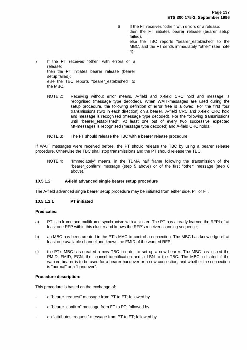
Page 137ETS 300 175-3: September 1996
6 If the FT receives "other" with errors or a release:then the FT initiates bearer release (bearer setupfailed),else the TBC reports "bearer_established" to theMBC, and the FT sends immediately "other" (see note4).
7 If the PT receives "other" with errors or arelease:then the PT initiates bearer release (bearersetup failed);else the TBC reports "bearer_established" tothe MBC.
NOTE 2: Receiving without error means, A-field and X-field CRC hold and message isrecognised (message type decoded). When WAIT-messages are used during thesetup procedure, the following definition of error free is allowed: For the first fourtransmissions (two in each direction) on a bearer, A-field CRC and X-field CRC holdand message is recognised (message type decoded). For the following transmissionsuntil "bearer_established": At least one out of every two successive expectedMt-messages is recognised (message type decoded) and A-field CRC holds.
NOTE 3: The FT should release the TBC with a bearer release procedure.
If WAIT messages were received before, the PT should release the TBC by using a bearer releaseprocedure. Otherwise the TBC shall stop transmissions and the PT should release the TBC.
NOTE 4: "Immediately" means, in the TDMA half frame following the transmission of the"bearer_confirm" message (step 5 above) or of the first "other" message (step 6above).
10.5.1.2 A-field advanced single bearer setup procedure
The A-field advanced single bearer setup procedure may be initiated from either side, PT or FT.
10.5.1.2.1 PT initiated
Predicates:
a) PT is in frame and multiframe synchronism with a cluster. The PT has already learned the RFPI of atleast one RFP within this cluster and knows the RFP's receiver scanning sequence;
b) an MBC has been created in the PT's MAC to control a connection. The MBC has knowledge of atleast one available channel and knows the FMID of the wanted RFP;
c) the PT's MBC has created a new TBC in order to set up a new bearer. The MBC has issued thePMID, FMID, ECN, the channel identification and a LBN to the TBC. The MBC indicated if thewanted bearer is to be used for a bearer handover or a new connection, and whether the connectionis "normal" or a "handover".
Procedure description:
This procedure is based on the exchange of:
- a "bearer_request" message from PT to FT; followed by
- a "bearer_confirm" message from FT to PT; followed by
- an "attributes_request" message from PT to FT; followed by
Page 138ETS 300 175-3: September 1996
- an "attributes_confirm" message from FT to PT; followed by
- an "other" message from PT to FT; followed by
- an "other" message from FT to PT.
The "bearer_request" message is one of the following messages defined in subclause 7.2.5.3:
- the ACCESS_REQUEST message;
- the BEARER_HANDOVER_REQUEST message;
- the CONNECTION_HANDOVER_REQUEST message.
The "bearer_confirm" message is:
- the BEARER_CONFIRM message of subclause 7.2.5.3.
The "attributes_request" message is:
- the ATTRIBUTES_T message (subclause 7.2.5.3). The Request/Confirm (R/C) bit is set to 0.
The "attributes_confirm" message is:
- the ATTRIBUTES_T message (subclause 7.2.5.3). The Request/Confirm (R/C) bit is set to 1.
All service parameters in the ATTRIBUTES_T messages used as the "attributes_request" and"attributes_confirm" messages shall be the same. The only difference is the setting of the R/C bit.
The messages are carried in the tail of the A-field. Except for the "other" message all messages are MTmessages of the advanced control message set. With the MT messages the FT and PT exchange theirMAC identities and agree the service type. Between the needed setup messages the exchange of someWAIT messages (see subclause 7.2.5.3) is allowed. The FMID contained in the WAIT and the"bearer_confirm" messages shall be the same as that in the "bearer_request" message. The "other"message is used to switch the bearer state at the receiving end to Bearer_Established.
The bearer request message and the first response (confirm or WAIT message) from the called side mayappear in any frame, overriding the rules of the T-Mux algorithm described in subclause 6.2.2.1. This firstresponse of the called side shall occur in the TDMA half frame following the successful reception of therequest message. Until the PT transmits the "other" message in a successful bearer setup, the MACcontrol messages following the request shall occupy all allowed tails for MT. The T-Mux algorithm defineswhich tails are allowed. The "other" messages are any A-field messages transmitted in successive TDMAhalf frames following that half frame in which the PT received the bearer confirm message.
Before Bearer_Established, the B-field need not contain valid I-channel data. If the U-type multiplex is usedduring setup and no valid I-channel data is available, it is recommended that all bits in the B-field are set to"0". In the first transmission the PT may send a setup request also in the B-field. In this case the FT canchoose to proceed with an A-field bearer setup (this procedure) or a B-field setup (seesubclause 10.5.1.3).
Independent of the current encryption mode of the connection (enabled or disabled) bearer setup startsalways in "clear" (encryption disabled). In case of bearer handover, transmissions on the new bearer areswitched to the current encryption mode of the connection immediately after the second "other" messagewas transmitted/received.

Page 139ETS 300 175-3: September 1996
Procedure:
1 PT transmits one "bearer_request" at the righttime on a given available channel (selectiondefined in subclause 11.4.2) to one of its knownRFPs using the "first PT transmission" headercode given in subclause 7.1.2.
2 FT receives "bearer_request" error free (see note 3)with correct FMID and creates new TBC elseprocedure ends (bearer setup failed, no TBC = notransmissions).
NOTE 1: It is assumed that an FT which does not have the capacity to create a new TBC (e.g.simple residential system, call in progress, no bearer or connection handovercapability) is not listening to bearer request messages and, therefore, cannot receivethis message. If the MBC can create a new TBC this FMID check has to be donewithin one TDMA half frame = 5 ms.
�����������������������������������������������������������������������������WHILE (FT not ready to transmit "bearer_confirm") DO BEGIN
a) FT sends WAIT.
b) If the PT receives WAIT error free:then the PT responds with WAIT;else procedure ends (bearer setup failed).
If WAIT messages were received before, the PT should release the TBC by using a bearer releaseprocedure. Otherwise the TBC shall stop transmissions and the PT should release the TBC.
c) If�the FT receives WAIT message error freethen continue;else procedure ends with FT initiating bearer release(bearer setup failed).
END {WHILE}�����������������������������������������������������������������������������
3 FT sHnds "bearer_confirm";
4 If the PT receives "bearer_confirm" error free:then continue;else the procedure ends (bearer setup failed).
�����������������������������������������������������������������������������
If WAIT messages were received before, the PT should release the TBC by using a bearer releaseprocedure. Otherwise the TBC shall stop transmissions and the PT should release the TBC.
WHILE (PT not ready to transmit "attributes_request") DO BEGIN
a) PT sends WAIT.
b) If the FT receives WAIT error free:then the FT responds with WAIT;else procedure ends (bearer setup failed), with the FTinitiating a bearer release.
c) If the PT receives WAIT message error free:then continue;else procedure ends (bearer setup failed) withthe PT initiating a bearer release.

Page 140ETS 300 175-3: September 1996
END {WHILE}�����������������������������������������������������������������������������
5 PT sends "attributes_request".
6 FT receives "attributes_request" error free elseprocedure ends (bearer setup failed) with FT initiatinga bearer release.
7 FT's TBC asks LLME for an MBC identified by (ARI +PMID + ECN) to be connected. If the FT cannotprovide an MBC the procedure ends (bearer setupfailed) with FT initiating a bearer release.
8 FT's TBC asks MBC for connection with the receivedlogical bearer number (LBN). If the MBC cannotaccept a new bearer with this LBN the procedure ends(bearer setup failed) with FT initiating a bearerrelease.
�����������������������������������������������������������������������������WHILE (FT not ready to transmit "attributes_confirm") DO BEGIN
a) FT sends WAIT.
b) If PT receives WAIT error free:then the PT responds with WAIT;else procedure ends (bearer setup failed) withPT initiating a bearer release.
c) If FT receives WAIT message error free:then continue;else procedure ends with FT initiating bearer release(bearer setup failed).
END {WHILE}�����������������������������������������������������������������������������
9 FT sends "attributes_confirm".
10 If PT receives "attributes_confirm" without error:then continue;else the procedure ends (bearer setup failed)with PT initiating bearer release.
11 PT sends immediately "other" (see note 3).
12 If the FT receives "other" with errors or a release:then the FT initiates bearer release (bearer setupfailed);else the TBC reports "bearer_established" to theMBC.
13 FT sends immediately "other" (see note 3).
14 If the PT receives "other" with errors or arelease:then the PT initiates bearer release (bearersetup failed);else the TBC reports "bearer_established" tothe MBC.

Page 141ETS 300 175-3: September 1996
NOTE 2: Receiving without error means A-field and X-field CRC hold and message is recognised(message type decoded).
If WAIT messages were received before, the PT should release the TBC by using a bearer releaseprocedure. Otherwise the TBC shall stop transmissions and the PT should release the TBC.
NOTE 3: "immediately" means, In the TDMA half frame following the transmission of the"attributes_confirm" message (step 11) or of the first "other" message (step 13).
10.5.1.2.2 FT initiated
Predicates:
a) For setting up the first bearer of a connection: the PT is location registered with the FT and hasinformed the FT of the RFPI of the RFP that it was locked to;
b) the PT is scanning all channels of the FT, using the same scanning sequence as the FT or the FThas received a LISTEN-channel list message;
c) an MBC has been created in the FT's MAC to control a connection. The MBC has knowledge of atleast one available channel;
d) the FT's MBC has created a new TBC in order to set up a new bearer. The MBC has issued PMID,FMID, ECN, the physical channel identification and a new LBN for this connection to the TBC.
Procedure description:
Same as in subclause 10.5.1.2.1 with the following two exceptions:
- change transmission direction of all messages;
- the "bearer_request" message cannot be the BEARER_HANDOVER_REQUEST message asdefined in subclause 7.2.5.3. Bearer handover of a duplex bearer is always initiated by the PT.
Procedure:
Same procedure as PT initiated with following changes:
- exchange names PT and FT in procedure steps;
- change PMID in step 2 to FMID.
Step 1 is changed to:
FT transmits one "bearer_request" at the right time on a given available channel (selection defined insubcaluse 11.4.3) to its known PT.
10.5.1.3 B-field single bearer setup procedure
The B-field single bearer setup procedure may be initiated from either side, PT or FT.
10.5.1.3.1 PT initiated
During bearer setup the A-field tail messages follow the normal T-MUX rules, except for the firsttransmission of the PT. The first transmission of the PT is labelled in the header's tail identification and thetail carries either a MT message indicating that the connection uses B-field setup (see subclause 7.2.5.8).
Predicates:

Page 142ETS 300 175-3: September 1996
the same as in subclause 10.5.1.2.
Procedure description:
this procedure is based on the exchange of:
- a "bearer_request" message from PT to FT; followed by
- a "bearer_confirm" message from FT to PT; followed by
- an "other" message from PT to FT; followed by
- an "other" message from FT to PT.
The "bearer_request" message is:
- the BEARER_REQUEST message of subclause 7.3.3.2 where the second header indicatesACCESS_REQUEST, BEARER_HANDOVER_REQUEST orCONNECTION_HANDOVER_REQUEST.
The "bearer_confirm" message is:
- the BEARER_CONFIRM message of subclause 7.3.3.3.
All service parameters in the bearer request and the bearer confirm message shall be the same.
The messages are carried in at least the B0 subfield. The bearer request and bearer confirm messagesare extended MAC control. Between request and confirm the exchange of some WAIT messages (seesubclause 7.3.3.4) are allowed in subfield B0. The FMID contained in the WAIT and the "bearer_confirm"messages shall be the same as that in the "bearer_request" message. The "other" message is used toswitch the bearer state at the receiving end to Bearer_Established.
Independent of the current encryption mode of the connection (enabled or disabled) bearer setup startsalways in "clear" (encryption disabled). In case of bearer handover, transmissions on the new bearer areswitched to the current encryption mode of the connection immediately after the second "other" messagewas transmitted/received.
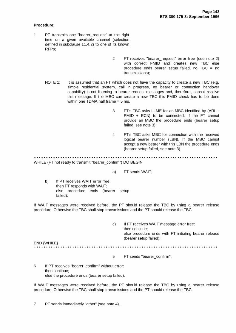
Page 143ETS 300 175-3: September 1996
Procedure:
1 PT transmits one "bearer_request" at the righttime on a given available channel (selectiondefined in subclause 11.4.2) to one of its knownRFPs;
2 FT receives "bearer_request" error free (see note 2)with correct FMID and creates new TBC elseprocedure ends bearer setup failed, no TBC = notransmissions);
NOTE 1: It is assumed that an FT which does not have the capacity to create a new TBC (e.g.simple residential system, call in progress, no bearer or connection handovercapability) is not listening to bearer request messages and, therefore, cannot receivethis message. If the MBC can create a new TBC this FMID check has to be donewithin one TDMA half frame = 5 ms.
3 FT's TBC asks LLME for an MBC identified by (ARI +PMID + ECN) to be connected. If the FT cannotprovide an MBC the procedure ends (bearer setupfailed, see note 3);
4 FT's TBC asks MBC for connection with the receivedlogical bearer number (LBN). If the MBC cannotaccept a new bearer with this LBN the procedure ends(bearer setup failed, see note 3).
�����������������������������������������������������������������������������WHILE (FT not ready to transmit "bearer_confirm") DO BEGIN
a) FT sends WAIT;
b) If PT receives WAIT error free:then PT responds with WAIT;else procedure ends (bearer setupfailed);
If WAIT messages were received before, the PT should release the TBC by using a bearer releaseprocedure. Otherwise the TBC shall stop transmissions and the PT should release the TBC.
c) If FT receives WAIT message error free:then continue;else procedure ends with FT initiating bearer release(bearer setup failed);
END {WHILE}�����������������������������������������������������������������������������
5 FT sends "bearer_confirm";
6 If PT receives "bearer_confirm" without error:then continue;else the procedure ends (bearer setup failed).
If WAIT messages were received before, the PT should release the TBC by using a bearer releaseprocedure. Otherwise the TBC shall stop transmissions and the PT should release the TBC.
7 PT sends immediately "other" (see note 4).

Page 144ETS 300 175-3: September 1996
8 If the FT receives "other" with correct A-field andX-field CRCs :then the TBC reports "bearer_established" to theMBC;else the FT initiates bearer release (bearer setupfailed).
9 FT sends immediately "other" (see note 4).
10 If the PT receives "other" with correct A-fieldand X-field CRCs :then the TBC reports "bearer_established" tothe MBC;else the PT initiates bearer release (bearersetup failed).
NOTE 2: Except for the reception of the "bearer_request" message the expression "Receivederror free" means, that the A-field and all B-subfields are received without CRC failure.For the "bearer_request" message, the A-field and the B0-subfield shall be receivedwithout CRC error.
NOTE 3: The FT should release the TBC with a bearer release procedure.
If WAIT messages were received before, the PT should release the TBC by using a bearer releaseprocedure. Otherwise the TBC shall stop transmissions and the PT should release the TBC.
NOTE 4: "Immediately" means, In the TDMA half frame following the transmission of the"bearer_confirm" message (step 7) or of the first "other" message (step 9).
NOTE 5: The relevant MAC messages (bearer request, bearer confirm, WAIT and release) haveto be in subfield B0. Nevertheless duplication in other subfields is allowed.
10.5.1.3.2 FT initiated
During bearer setup the A-field tail messages follow the normal T-MUX rules.
Predicates:
same as in subclause 10.5.1.2.2
Procedure description:
same as in subclause 10.5.1.3.1 with the following two exceptions:
- change transmission direction of all messages;
- the second header in the BEARER_REQUEST message cannot indicate bearer handover. Bearerhandover of a duplex bearer is always initiated by the PT.
Procedure:
same procedure as PT initiated with following changes:
- exchange names PT and FT;
- change FMID in step 2 to PMID;
- step 1 changes to:
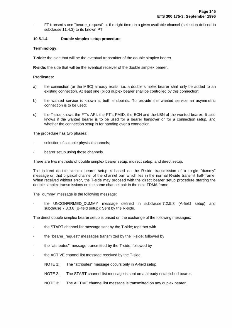
Page 145ETS 300 175-3: September 1996
- FT transmits one "bearer_request" at the right time on a given available channel (selection defined insubclause 11.4.3) to its known PT.
10.5.1.4 Double simplex setup procedure
Terminology:
T-side: the side that will be the eventual transmitter of the double simplex bearer.
R-side: the side that will be the eventual receiver of the double simplex bearer.
Predicates:
a) the connection (or the MBC) already exists, i.e. a double simplex bearer shall only be added to anexisting connection. At least one (pilot) duplex bearer shall be controlled by this connection;
b) the wanted service is known at both endpoints. To provide the wanted service an asymmetricconnection is to be used;
c) the T-side knows the FT's ARI, the PT's PMID, the ECN and the LBN of the wanted bearer. It alsoknows if the wanted bearer is to be used for a bearer handover or for a connection setup, andwhether the connection setup is for handing over a connection.
The procedure has two phases:
- selection of suitable physical channels;
- bearer setup using those channels.
There are two methods of double simplex bearer setup: indirect setup, and direct setup.
The indirect double simplex bearer setup is based on the R-side transmission of a single "dummy"message on that physical channel of the channel pair which lies in the normal R-side transmit half-frame.When received without error, the T-side may proceed with the direct bearer setup procedure starting thedouble simplex transmissions on the same channel pair in the next TDMA frame.
The "dummy" message is the following message:
- the UNCONFIRMED_DUMMY message defined in subclause 7.2.5.3 (A-field setup) andsubclause 7.3.3.8 (B-field setup): Sent by the R-side.
The direct double simplex bearer setup is based on the exchange of the following messages:
- the START channel list message sent by the T-side; together with
- the "bearer_request" messages transmitted by the T-side; followed by
- the "attributes" message transmitted by the T-side; followed by
- the ACTIVE channel list message received by the T-side.
NOTE 1: The "attributes" message occurs only in A-field setup.
NOTE 2: The START channel list message is sent on a already established bearer.
NOTE 3: The ACTIVE channel list message is transmitted on any duplex bearer.

Page 146ETS 300 175-3: September 1996
The "bearer_request" message is the following message:
- the UNCONFIRMED_ACCESS_REQUEST message defined either in subclause 7.2.5.3 (A-fieldsetup) or in subclause 7.3.3.2 (B-field setup).
The "attributes" message for A-field setup is:
- the ATTRIB_T message (subclause 7.2.5.2). The Request/Confirm (R/C) bit is set to 0.
Channel selection procedure:
Prior to initiating an Indirect Setup, the R-side shall select a channel using the double simplex channelprocedures as described in subclause 11.4. The T-side shall not select the channel.
NOTE 4: Although the R-side only makes a single (backward) transmission, the channel selectionmust use the double simplex procedure.
The R-side should select other suitable physical channels for setup, and should indicate these to the T-sideusing indirect setup (the "dummy" message) or GOOD or LISTEN channel list messages.
NOTE 5: These channel list messages may be transmitted on any existing bearer of thisconnection, and may be MT messages or extended MAC control.
The T-side always initiates the double simplex transmissions as described in the direct setup procedure.When initiating this procedure, the T-side should give preference to accepting any indirect setupprocedures from the R-side.
When selecting channels for the direct procedure (i.e. when not responding to an indirect setuptransmission) the T-side should select a channel in the following order of preference:
a) a channel indicated by a LISTEN message;
b) any channel that is aligned to a predefined R-side scanning pattern (see subclause 11.8 for RFPs,and subclause 11.9 for PPs);
c) a channel indicated by a GOOD message.
In these cases the T-side channel selection shall use the double simplex channel selection procedures asdescribed in subclause 11.4.
Before selecting a physical channel, the T-side should attempt to receive one (or more) transmission onthat channel. If a connectionless or broadcast transmission is received as indicated by the BA coding (seesubclause 7.1.4) the physical channel should not be used.
NOTE 6: Connectionless and broadcast transmissions should be given special treatment, toimprove their reliability.
Indirect setup procedure:
The indirect procedure enables the R-side to propose a channel to set up a double simplex bearer.Nevertheless, it is the T-side's responsibility to accept the proposal.
R-side proposal:
The R-side shall initiate the set up by transmitting a "dummy" message in the normal half of the TDMAframe. This transmission shall be aligned to a known T-side scanning pattern (see subclauses 11.8 and11.9). The R-side shall then attempt to receive a direct double simplex set up on these channels as thougha LISTEN message had been sent (i.e. the R-side shall listen to the channel for 4 TDMA frames).

Page 147ETS 300 175-3: September 1996
If the "dummy" message is received successfully by the T-side, the T-side should initiate a direct doublesimplex setup on that channel using the procedure listed below. If the T-side responds to this "dummy"transmission, it shall commence double simplex transmissions in the TDMA frame immediately following theTDMA frame that contained the DUMMY message.
Direct setup procedure:
The T-side shall report a setup attempt on the selected physical channels by issuing a START channel listmessage. This message shall be transmitted only once for one setup attempt on any bearer of thisconnection. The START message shall be transmitted on at least one established bearer when respondingto a GOOD message (channel selection (c) above; see subclause 10.5.2 for the channel list messages).
NOTE 7: The START message may be duplicated on more than one bearer, provided that alltransmissions of the START message occur within a single TDMA frame.
NOTE 8: The START message may be a MT message or extended MAC control.
At the T-side the MBC creates a TBC and shall start transmissions on both physical channels of the newbearer in the same TDMA frame if the R-side scanning pattern is known (channel selection type (b) above)or if the R-side has a temporary TBC installed (channel selection type (a) above). Otherwise, the TBCshall start transmissions on both physical channels of the new bearer in the TDMA frame following thatframe in which the START channel list message was transmitted. Transmissions on a new bearer shallstart in "clear" (encryption disabled), and for encrypted connections the transmissions shall be switched to"encrypted" at the third TDMA frame boundary after the transmission of the START message.
NOTE 9: This ensures that the next two TDMA frames, which may contain B-field setupmessages, shall always be transmitted in "clear".
For A -field setup:
The first transmissions on both channels may violate the T-MUX rules defined in subclause 6.2.2.1and at least one channel shall contain the "bearer_request" message in the A-field tail. Thismessage shall be labelled in the A-field header as a MT message. The next two allowed TDMAframes for MT tails (T-MUX algorithm) shall also be used for the bearer setup. In the first of theseframes the "bearer_request" message shall be repeated on at least one channel, and in the secondthe "attributes" message shall be transmitted on at least one channel.
NOTE 10: The A-field setup may transmit the "bearer_request" message in one channel, and the"attributes" message in the other channel.
For B-field setup:
The first transmission on each channel shall contain the "bearer_request" message. This messageshall be repeated in the following TDMA frame on both physical channels of the new bearer if theR-side scanning is not known and no temporary TBC is present at the R-side, i.e., only for channelselection type (c): response to a GOOD message. The "bearer_request" message shall always bepresent in the B0 subfield and may be duplicated into other subfields.
NOTE 11: Further transmissions of the "bearer_request" message are allowed, subject to therules in the following paragraphs.
NOTE 12: The minimum retransmission of the "bearer_request" message defines the earliest pointat which "early" data transmission may occur.
In certain cases the double simplex transmissions shall be limited to a maximum period of 2 TDMA frames.This limit shall apply only if the T-side has not received a GOOD, ACTIVE, or a LISTEN message for theselected double simplex channel.
NOTE 13: A suitable GOOD, ACTIVE, or LISTEN message may be received at any time up to theexpiry of this transmission limit. In cases a) and c) above, the GOOD or LISTEN
Page 148ETS 300 175-3: September 1996
message will have been received before the double simplex transmissions start, and nospecial action is needed.
NOTE 14: In case b), a rapid response is needed from the R-side if a partial setup attempt isreceived by the R-side. The immediate transmission of a LISTEN message is thereforerecommended.
The T-side shall now wait for a confirmation from the R-side of successful double simplex bearerestablishment. A confirmation shall be indicated by the reception of an ACTIVE channel list message forthis pair of physical channels on any existing bearer of the connection.
NOTE 15: This ACTIVE channel list message may also occur as a reply to a QUERY_N or aQUERY_H channel list message issued by the initiating side.
At the T-side the reception of the ACTIVE channel list message switches the bearer state toBearer_Established. If this message is not received within T212 frames after the first bearer requestmessage was transmitted or a POOR channel list message is received for this bearer at any time duringbearer setup, the bearer setup has failed and the MAC releases the new bearer with the unacknowledgedrelease procedure (see subclause 10.7.2.1).
At the R-side of a double simplex bearer a correctly received START channel list message may occur onany established bearer, and shall immediately alter the receiver scanning pattern if this is possible.
When a scanning change is possible, the R-side receiver scanner shall listen on the indicated pair ofphysical channels during at least four TDMA frames following that frame in which the START message wasreceived. If a LISTEN message has not already been sent as part of the channel selection procedure, theR-side should immediately return a LISTEN message for the indicated channels.
NOTE 16: The LISTEN message may be transmitted in all cases.
If a change to the scanning is not possible, the R-side should respond with a POOR channel list message.
At the R-side, a "bearer_request" message may be received on any physical channel. The physical channelshould also be indicated by the receipt of a START message, but the receipt of the START message onlyessential in certain cases (notably for encrypted connections).
NOTE 17: The first "bearer_request" message may occur before the START message, even forencrypted connections.
For encrypted connections, a successfully established TBC shall only be connected to the MBC if a STARTmessage has been received for that bearer. Otherwise the TBC shall be released.
NOTE 18: The START message is essential for encrypted connections to enable the start ofencryption.
For connections which are not encrypted, a successfully established TBC shall be connected to the MBCeven if the START message is not received.
In both cases, successful establishment of a TBC requires the following setup messages to be received.
For A -field setup:
If a "bearer_request" message is received on at least one channel a TBC shall be created. The TBCshall try to receive the repeated "bearer_request" and the "attributes" messages on both physicalchannels. If both these messages are received within 3 frames without errors, and at least onemessage is received without errors on each channel, the TBC should be connected to the MBC andthe bearer shall switch its state to Bearer_Established. Otherwise, the MAC shall release the TBC.

Page 149ETS 300 175-3: September 1996
For B-field setup:
If a "bearer_request" message is received on at least one channel a TBC shall be created. The TBCshall try to receive the repeated "bearer_request" message on both physical channels. If thismessage is received within 2 frames without errors on both physical channels the TBC should beconnected to the MBC and the bearer shall switch its state to Bearer_Established. Otherwise, theMAC shall release the TBC.
As soon as a new double simplex bearer TBC is established, the MBC at the receiving end shall report thisevent with an ACTIVE channel list message to the T-side. This message shall be transmitted on anyestablished bearer of the connection.
If the R-side detects an unsuccessful setup attempt (i.e. at least one setup message is received for agiven bearer, but the full setup criteria as given above have not been achieved), then the R-side shouldrequest an immediate halt to the setup attempt by sending a POOR channel list message.
NOTE 19: This action is not essential. The setup attempt should terminate due to lack of apositive message.
I-channel data transmission may start on both physical channels as soon as there is available capacity. ForA-field setup this can occur in the first transmission, but for B-field setup at least two setup messages haveto be transmitted. Any I-channel data transmitted before the bearer state is "established" (i.e. beforereceipt of the ACTIVE channel list message) may be lost if the bearer setup fails.
NOTE 20: Data transfer on an unestablished bearer is unreliable. In particular, the IP errorcorrected service cannot return acknowledgements until it has been connected to theMBC.
10.5.1.5 Physical setup
A physical setup shall always be REP initiated, as explained in the following overview.
The calling side doesn't require the creation of a new MBC at the called side.
Called side:
- on the called side a new TBC is created by receiving a "REP_bearer_request" message, includingthe MAC addresses PMID and FMID on the scanned physical channel. The message type alsocontains the information that the new bearer belongs to a physical connection.
MBC identification:
The TBC has to receive all necessary parameters to identify an MBC.
The MBC is fully identified after:
a) receiving with "REP_bearer_request" message either a REP_access request or aREP_bearer_handover request (see subclause 7.2.5.11), including the calling address PMID anddefining the connection type as physical; and
b) receiving the REP_channel_map_request (see subclause 7.2.5.11) message which indicates theduplex bearer to which the physical setup bearer has to be linked. This message is necessary onlyfor a new bearer setup; in case of a bearer handover request, the old mapping still stays effective.The MBC to refer to is the one to which belongs the TBC of the linked bearer.
The TBC issues a PMID, ARI and the REP_channel_map.request message, when received, to the referredMBC and indicates the purpose of the wanted connection (bearer handover or a new setup).

Page 150ETS 300 175-3: September 1996
The MBC can now decide:
a) to release the TBC;b) to accept the TBC.
Procedure description:
The procedure of a physical bearer setup is identical to the basic bearer setup procedure described insubclause 10.5.1, where:
- the PT is REP and the FT could be also a REP;- the exchanged Mt messages belong to the REP control set (see ETS 300 175-3 [3],
subclause 7.2.5.11);- the bearer_request message can be either a REP_access.request or a
REP_bearer_handover.request message.
10.5.1.6 Mapping procedure
This procedure allows the creation of a double duplex bearer, after two duplex bearers have been setupbetween two far ends. When one of the two duplex bearers already belongs to a double duplex bearer theprocedure is called "interlacing".
After receiving without errors the REP_channel_map.request onto a duplex bearer, the receiving side candecide:
a) to Accept to map together the indicated channels;b) to Reject to map together the indicated channels.
While not ready to send REP_channel_map.confirm, the receiving side can send wait messages: thesending side shall answer with wait messages; when ready it shall send back onto the same duplex bearerthe REP_channel_map.confirm message setting the A/R flag to Accepted (case (a)) or Rejected (case(b)).
Case (b) may apply when interlacing of the two duplex bearers is requested and the receiving side doesnot support "interlacing".
If it is case (a), a double duplex bearer has been created.
Within the double duplex bearer the two duplex bearers shall exchange their simplex bearers such that theinformation flow, for the uplink transmission direction, shall use the uplink simplex bearer of one duplexbearer and, for the downlink transmission direction, the downlink simplex bearer of the other duplex bearer.The figure at the end of this subclause shows an example of information flow within a double duplexbearer.
Within the REP_channel_map.request message, the first SN and CN fields refer to the "Master channel": itis the channel whose reference connection shall become the reference connection for the mapped bearers.
The release of one of the two duplex bearers composing the double duplex shall cancel the link, given withthe mapping procedure, between the surviving duplex bearer and the released one.
The REP_channel_map.req message may over-ride the T-Mux algorithm (refer to subclause 6.2.2.1) whentransmitted as a first "other" message (refer to subclause 10.5) during a bearer setup procedure. The firstresponse (REP_channel_map.confirm or wait message) shall occur in the TDMA half frame following thesuccessful reception of the REP_channel_map.req from the receiving side and may also over-ride theT-Mux algorithm. The TBC shall report "bearer established" after the mapping procedure is successfullycompleted (i.e. the double duplex bearer has been created).
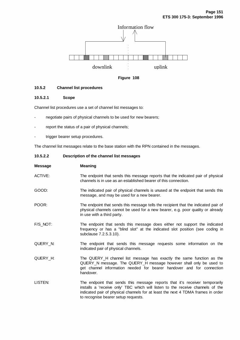
Page 151ETS 300 175-3: September 1996
Information flow
downlink uplink
Figure 108
10.5.2 Channel list procedures
10.5.2.1 Scope
Channel list procedures use a set of channel list messages to:
- negotiate pairs of physical channels to be used for new bearers;
- report the status of a pair of physical channels;
- trigger bearer setup procedures.
The channel list messages relate to the base station with the RPN contained in the messages.
10.5.2.2 Description of the channel list messages
Message Meaning
ACTIVE: The endpoint that sends this message reports that the indicated pair of physicalchannels is in use as an established bearer of this connection.
GOOD: The indicated pair of physical channels is unused at the endpoint that sends thismessage, and may be used for a new bearer.
POOR: The endpoint that sends this message tells the recipient that the indicated pair ofphysical channels cannot be used for a new bearer, e.g. poor quality or alreadyin use with a third party.
F/S_NOT: The endpoint that sends this message does either not support the indicatedfrequency or has a "blind slot" at the indicated slot position (see coding insubclause 7.2.5.3.10).
QUERY_N: The endpoint that sends this message requests some information on theindicated pair of physical channels.
QUERY_H: The QUERY_H channel list message has exactly the same function as theQUERY_N message. The QUERY_H message however shall only be used toget channel information needed for bearer handover and for connectionhandover.
LISTEN: The endpoint that sends this message reports that it's receiver temporarilyinstalls a 'receive only' TBC which will listen to the receive channels of theindicated pair of physical channels for at least the next 4 TDMA frames in orderto recognise bearer setup requests.
Page 152ETS 300 175-3: September 1996
START: The endpoint that sends this message has selected the indicated pair of physicalchannels for a new bearer and shall transmit on this bearer in at least the nextTDMA frame. If the channel pair is accessible and no TBC is installed at thereceiving endpoint of a START message, the receiving side should install atemporary 'receive only' TBC to recognise bearer setup requests.
10.5.2.3 Usage of the channel list messages
Message Meaning
ACTIVE: This message shall be used by the receiving side to confirm the establishment ofa double simplex bearer, and may be used from either side at any time to reportthe status of the physical channel pair.
GOOD, POOR,F/S_NOT: These messages may be used at any time from either side to report the status
of the physical channel pair.
QUERY_N: This message may be used at any time from either side.
QUERY_H: This message is allowed only during a handover operation (bearer orconnection).
LISTEN: This message may be used at any time.
NOTE 1: Subclauses 10.2.4.3.1 to 10.2.4.3.3 describe which endpoint is allowed to initiatebearer setup. Therefore, a LISTEN message transmitted in the wrong direction ismeaningless.
START: This message is used to announce double simplex bearer setup attempts(handover or initial setup) on the indicated channel pair and to trigger encryptionon those bearers. For one setup attempt the START channel list message shallbe sent on one or more bearers within one TDMA frame. The START channel listmessage is sent by the PT when the bearer belongs to an asymmetric uplinkconnection, and by the FT when the connection is asymmetric downlink.
The START message may also be used to announce duplex bearer setupattempts on channels other than the scanned channels (refer to subclauses 11.8and 11.9). When used, the message is sent on one or more bearers within onesingle TDMA frame. FTs may use this mechanism only when the connection isasymmetric downlink, and PTs when the connection is symmetric or asymmetricuplink.
Except for the START message, all channel list messages may be retransmitted. When not explicitlyprohibited, the channel list messages can be sent on any bearer of the connection, even during bearersetup (if the capacity is available).
NOTE 2: There is no guarantee the receiving endpoint will decode the channel list messagesduring bearer setup. It is recommended to transmit important messages which mayinfluence setup procedures (i.e. LISTEN, START, and ACTIVE) only on establishedbearers.

Page 153ETS 300 175-3: September 1996
The following channel list messages should produce a response from the receiving entity:
- QUERY_N or QUERY_H messages:
- Message responses shall be: GOOD, POOR, ACTIVE, LISTEN or F/S_NOT.
- START message for double simplex bearer:
- Message response shall be: ACTIVE or POOR.
10.6 C/O bearer handover
10.6.1 General
The MAC layer provides PTs and FTs with several mechanisms to control the quality of transmissions andreceptions. Bearer handover may be initiated either by using this quality information or by receiving abearer handover request message from the far end (see subclauses 7.2.5.5 and 7.3.5). For duplexbearers the PT only can initiate a bearer handover, and for double simplex bearers the transmitting sideonly can initiate a bearer handover. The existing bearer can be maintained until the new bearer has beenestablished. During bearer handover the two bearers can operate in parallel.
NOTE 1: Bearer handover requires that an MBC for the connection exists on both sides, PT andFT, and that the new selected RFP at the fixed side belongs to the same cluster.
PTs should use bearer handover to attempt to connect to the best RFP of the cluster in which theconnection is established. This may be the same RFP as the existing bearer, or may be a new RFP.
DECT equipments may have several indicators to monitor reception quality:
- the A-field CRC;
- the X-field CRC;
- the CRCs of the B-subfields in protected mode (E-type or U-type for IP);
- X-field to Z-field comparison (for Z-field refer to ETS 300 175-2 [2]);
- link identity information;
- synchronisation pulse;
- clock jitter;
- signal strength;
- . . .
To control the quality of transmissions the MAC layer uses the reports from the far end, coded in two bits:
- the (Q1,Q2) bits or the (BCK,Q2) bits or the (BCK,ACK) bits (see subclauses 7.1.1 and 7.3.5.4).
There are no specified rules for the PT which define when a bearer handover attempt has to be made. Forsystem reasons the maximum rate at which bearer handovers can be performed is limited by a simpletimer. No more than two successful bearer handovers should occur within T202 seconds.
NOTE 2: This should not be confused with multiple attempts at handover, but following onesuccessful handover, a new handover cannot be attempted immediately.
Different handover procedures exist for duplex and double simplex bearers.

Page 154ETS 300 175-3: September 1996
10.6.2 Duplex bearer handover procedure
The setup of a new bearer for duplex bearer handover is always initiated by the PT. The MBC of the PTshall have knowledge of at least one available channel and shall know the address (FMID) of the wantedFT. The MBC creates a TBC and issues called address (PMID/FMID) and the physical channel descriptionto the new TBC. The MBC indicates to the TBC that the wanted bearer is used for a bearer handover andwhich bearer setup procedure shall be used. In addition, for advanced connections the MBC issues thenew TBC with the ECN and the LBN, which is also assigned to the TBC of the bearer which has to behanded over.
The TBC tries to set up a new bearer using one of the single bearer setup procedures described insubclause 10.5.1:
- the basic bearer setup procedure for all basic connections;
- the A-field single bearer setup procedure or the B-field single bearer setup procedure for advancedconnections.
At the end of all these procedures the TBC reports either "bearer_established" or "bearer_setup_failed" tothe MBC.
NOTE 1: At the called side these messages only occur if a bearer setup attempt was detected(TBC created).
If the bearer setup failed the MBC can reattempt a bearer handover with the same procedure, subject tousing a new available channel each time (see subclause 11.4) and/or accessing a new RFP. Within anytime window of T202 seconds at most N201 bearer setup attempts shall occur for a bearer handover ofone particular bearer.
An MBC assumes that a bearer setup was successful when the TBC reported "bearer_established".Immediately after this TBC report the MAC switches the new bearer to the same E/U multiplex as used bythe old bearer. For U-type databursts all following transmissions shall contain valid I-channel data.
NOTE 2: In advanced connections the "new" and the "old" bearers have the same LBN number.
In basic connections, two bearers shall only occur during bearer handover. There is no LBN, i.e. the "new"and the "old" bearer are the only bearers of the connection.
For a limited time the MBC may maintain both TBCs, controlling the new and the old bearer. The MBC inthe FT decides when and which one of the two TBCs is released with a bearer release procedure. The FTshall invoke this bearer release procedure within a time interval of T203 after the new bearer wasestablished (TBC reported "bearer_established").
NOTE 3: During the time where the new and the old bearer are maintained, both bearerstogether form one logical bearer (see subclause 5.5.2).
For the limited time where both bearers are established:
Except for IN_minimum_delay services all I-channel data transmitted in one TDMA half frame is the samefor both bearers (see data flow control, subclause 8.4).
For IN_minimum_delay services I-channel data transmitted in one TDMA frame may be different for bothbearers (see subclause 8.4).

Page 155ETS 300 175-3: September 1996
10.6.3 Double simplex bearer handover
The receiving endpoint of a specific double simplex bearer may request a bearer handover. The requestmay be transmitted on any bearer in reverse direction. The request message is defined as a MT messagein subclause 7.2.5.5 and as an extended MAC control message in subclause 7.3.5.
By receiving a bearer handover request the transmitting side of a double simplex bearer may eitherinitialise a bearer handover, reject the handover request with a BEARER_HANDOVER_REJECT message(see subclauses 7.2.5.5 and 7.3.5) or not react upon this request message.
Initialisation of a bearer handover starts with the negotiation of a new pair of physical channels. This isdone using the channel list procedures. The new bearer is set up with the double simplex setup procedure(see subclause 10.5.1.4), except that the UNCONFIRMED_HANDOVER message is used in place of theUNCONFIRMED_ACCESS_REQUEST message. The same logical bearer number LBN is assigned to thenew double simplex bearer as for the old bearer.
As soon as possible all I-channel information carried on this logical bearer is duplicated on both doublesimplex bearers.
This occurs no later than when the bearer is established, i.e. when the receiving end reports theacceptance of the new bearer with an ACTIVE message (see channel list procedure).
The initiating side shall reattempt to setup a new double simplex bearer at most N201 times within T202seconds.
NOTE 2: The relevant reattempts are those where the initiating side actually starts transmissionson a new bearer.
The new bearer setup is successful when the initiating side receives a confirmation, i.e. an ACTIVEmessage (subclauses 7.2.5.3.10 and 7.3.3.7) for this bearer. As soon as this message is received theinitiating side proceeds with a bearer release of the old double simplex bearer with the unacknowledgedrelease procedure (see subclause 10.7.2.1).
10.7 C/O bearer release
10.7.1 General
Bearer release describes the release of a TBC which controlled a duplex or a double simplex bearer.
A bearer release may be caused by several events:
a) the MBC on either side initiates a bearer release;
b) a bearer in setup phase cannot be connected to an MBC. Here the LLME initiates a bearer release(see single bearer setup procedures);
c) a TBC received faulty MAC messages during setup (see setup procedures);
d) the TBC releases the bearer due to a timeout. See handshaking requirement,(see subclause 11.5);
e) the TBC receives a release message error free.
NOTE 1: Event b) should not occur for double simplex bearers. Here the channels have to benegotiated before transmissions on a double simplex bearer start.

Page 156ETS 300 175-3: September 1996
A bearer release is initiated when on either side one of the events a) .. d) occurs. The FP shall onlyrelease a bearer if it has previously received a MAC control message referencing that bearer with correctFMID and PMID. Two bearer release procedures exist:
- the unacknowledged bearer release procedure; and
- the acknowledged bearer release procedure.
The unacknowledged bearer release procedure is always applied for a release of a duplex bearer, and fora double simplex bearer only if the MBC on the transmitting side decides to release the bearer. During thisprocedure MAC RELEASE messages (see subclause 7.2.5.3.13) are transmitted and afterwards the TBCstops transmitting. As a consequence, one of the events d) or e) will occur at the far end.
NOTE 2: If event d) is recognised at the far end a second bearer release procedure is initiated.
The acknowledged bearer release procedure is applied when the receiving end of a double simplex bearerdecides to release this bearer (events a), c) and d)). The release is negotiated on a duplex bearer.
NOTE 3: A connection release may interrupt this procedure.
10.7.2 Bearer release procedure description
10.7.2.1 Unacknowledged release procedure
The unacknowledged release procedure shall be applied to release duplex bearers, and double simplexbearers only by the transmitting side (exception for double simplex bearer, see subclause 10.7.2.3).
The unacknowledged release procedure uses the RELEASE message. This message allows the reasonfor a bearer release to be reported (only for advanced connections).
All sets of MAC connection control messages contain a RELEASE message. The unacknowledged bearerrelease procedure shall use the RELEASE message of that message set which was used to setup thebearer. If this message is transmitted in the B-field, the message may be duplicated into all subfields.
The RELEASE message appears twice without any warning, replacing the normal transmission. Themessage is sent two times in successive frames on that bearer which has to be released, and thetransmitting end releases the radio channel immediately afterwards. If the TBC is connected to an MBCand it was not the MBC's decision to release the bearer, the TBC reports this event to the MBC andindicates the reason. Finally the MAC releases the TBC.
The receiving end shall release the channel immediately after successful receipt of any RELEASEmessage. If the TBC is connected to an MBC the TBC shall report this event to the MBC and indicate thereason. The MAC shall release the TBC afterwards.
10.7.2.2 Acknowledged release procedure
The acknowledged release procedure is only used to release double simplex bearers when initiated by thereceiving end.
NOTE 1: The receiving end of double simplex bearers may only initiate an acknowledged releaseof any of these bearers when at least one established duplex bearer exists. Otherwisethe TBC is released without any negotiation.
The receiving end of a double simplex bearer may request a release of this bearer by sending a RELEASEmessage on any bearer in reverse direction. Within this message the setting of the LBN shall identify thedouble simplex bearer, and whenever necessary the reason shall be set.
During bearer handover it is possible that the receiving end initiates an acknowledged bearer release eitherfor the "new" bearer or for the "old" bearer due to a timeout. To avoid ambiguity the reason shall be set to

Page 157ETS 300 175-3: September 1996
"bearer handover successfully completed" or to "bearer handover failed". The first command means torelease the "old" bearer the latter command indicates to release the "new" bearer.
If the transmitting end of an established double simplex bearer receives a RELEASE message for thisbearer, it shall proceed with an unacknowledged bearer release.
The receiving end of a double simplex bearer may correctly receive a RELEASE command issued duringthe unacknowledged release procedure. In this case the bearer release is confirmed, the MAC releasesthe TBC and the procedure stops. If no release command is received within T213 frames after initiating theprocedure the receiving end of the double simplex bearer shall use the channel list procedure to verify thechannel status. The transmitting end may reply with an GOOD or a POOR message. These two messagesindicate that the bearer is released. The MAC releases the TBC and the procedure stops. If the reply isthe ACTIVE message the release procedure shall be repeated.
10.7.2.3 Fast release procedure
The fast release procedure allows to switch the transmission direction of double simplex bearers veryquickly.
The fast release procedure shall only be used during connection modification (see subclause 10.3) torelease double simplex bearers. The procedure is always initiated by the MBC of the transmitting side anduses the RELEASE message with the reason set to "reverse".
Both sets of advanced MAC connection control messages, A-field and B-field, contain this RELEASEmessage. The fast release procedure shall use the RELEASE message of that message set which wasused to setup the bearer. If this message is transmitted in the B-field, the message may be duplicated intoall subfields.
The RELEASE message appears in one TDMA frame on both physical channels of the double simplexbearer. The transmitting end releases the radio channel immediately afterwards and starts to scan on bothradio channels for at least 4 TDMA frames. Within this 4 frames the "old" receiving side is now allowed tosetup directly a double simplex bearer in the reverse direction.
The receiving TBC of a RELEASE message with the reason set to "reverse" shall report this event to theMBC. The MBC shall decide either to release the TBC or to setup a new double simplex bearer in reversedirection. Receiving a RELEASE message with reason set to "reverse" has the same effect as a normalrelease and a received LISTEN channel list message for this physical channel pair. To setup a new doublesimplex bearer the MBC proceeds with the double simplex setup procedure and takes into account that aequivalent to the LISTEN channel list message was already received.
NOTE: The "old" transmitting side of a double simplex bearer stops transmissions aftersending the RELEASE message. If the RELEASE message is not received correctly atimeout should cause a release on the "old" receiving side (see subclause 11.5).
10.7.2.4 REP relayed bearer release
In case of unacknowledged release procedure (refer to subclause 10.7.2.1) of a bearer which has beenmapped with another bearer (refer to subclause 10.5.1.6):
at the FT as transmitting side:
the radio channel and the associated TBC shall not be released after sending the RELEASE messages, IFit's an MBC decision to release the bearer and IF the channel is also interlaced with another channel (referto subclause 10.5.1.6 for definitions).
at the FT as receiving side:
the radio channel and the associated TBC shall not be released after successful receiving of a RELEASEmessage IF the channel is also interlaced with another channel.

Page 158ETS 300 175-3: September 1996
10.8 C/O data transfer
10.8.1 Higher layer associated signalling (C)
All higher layer control (CS and CF-channel data) is protected by a MAC layer ARQ procedure. Thisprocedure is based on the principle that a data transmitter shall retransmit CS and CF segments when noacknowledgments for these segments have been received.
For the transmission of C-channel data time windows called ARQ windows are defined. These ARQwindows start with the normal TDMA half frame for transmissions. Therefore, the windows are different forFT and PT:
- ARQ windows for FT start with slot 0;
- ARQ windows for PT start with slot 12.
10.8.1.1 CS-channel data
The CS data service is a low rate service with a variable throughput of maximum 2 kbit/s. Independent ofthe number of bearers controlled by an MBC a maximum of one CS segment may be transmitted in a givendirection in an ARQ window of 10 ms. The same segment may, however, be duplicated over severalbearers.
10.8.1.1.1 Transmission principle
a) Those TDMA frames where the T-MUX algorithm does not allow CT messages (seesubclause 6.2.2.1) shall not be used for transmissions of CS segments;
b) CS data shall be sent only on duplex bearers. The same CS segment may be sent on several duplexbearers during one frame. Only one CS segment shall be transmitted within one ARQ window;
c) if a CS segment is sent in one particular ARQ window the successful transmission of this segment isconfirmed when an acknowledgement is received in the second half of the same ARQ window onany of those duplex bearers which carried the CS segment. Successful acknowledgment is achievedwhen the A-field of at least one of these bearers was received by the sending side of the CSsegment without CRC failure and with the Q2 bit in the header set to 1. In the direction FT to PT anacknowledgment is also given when Q2 equals 0 and Q1 is set to 1 (Q1 and Q2 bit setting, seesubclause 10.8.1.3);
d) a CS segment shall be retransmitted until the successful transmission of this segment is confirmed.Retransmission shall be done before another CS segment is transmitted in the same data direction.
10.8.1.1.2 Numbering principle
a) A one bit packet number is assigned to each CS segment. The number shall alter for successive CSsegments. In databursts containing CS segments this packet number is transmitted in the tailidentification field of the A-field header (see subclause 7.1.2);
b) packet number "1" shall be assigned to the first CS segment transmitted by an MBC.
10.8.1.2 CF-channel data
A MAC_CO_DATA-req primitive carrying CF-channel data delivers a set of CF segments to the MBC. Thenumber of CF segments building this set may be equal to or less than the maximum number of acceptablesegments indicated by the MBC with the MAC_CO_DTR-ind primitive (see subclause 8.4). The maximumnumber shall always be chosen such that all CF segments can be transmitted in the B-field of onedataburst.

Page 159ETS 300 175-3: September 1996
CF-channel data is transmitted as sets of CF segments, a set of 1 segment for half slot, up to 4 segmentsfor full slot, and up to 10 segments for double slot. Thus either all the CF segments of one singleMAC_CO_DATA-req primitive are contained in the B-field of an E-type databurst or no CF data at all is inthe B-field. The mapping of the CF segments onto the B-field is described in subclause 6.2.2.3.
10.8.1.2.1 Transmission principle
a) CF data shall be sent only on duplex bearers. The same set of CF segments may be sent on severalduplex bearers during one ARQ window. Only one set of CF segments shall be transmitted withinone ARQ window;
b) if a set of CF segments is sent in one particular ARQ window the successful transmission of this setis confirmed when an acknowledgement is received in the second half of the same ARQ window onany of those bearers which carried the CF data. Successful acknowledgment is achieved when theA-field of at least one of these bearers was received without CRC failure and with the Q2 bit in theheader set to 1. (Q2 bit setting, see subclause 10.8.1.3);
c) a set of CF segments shall be retransmitted until the successful transmission of this set is confirmed.Retransmission shall be done before another set of CF segments is transmitted in the same datadirection.
NOTE 1: Retransmissions of an already acknowledged set of CF segments is allowed as long asno new set of CF segments is transmitted.
NOTE 2: Step c) implies that retransmissions may occur on another bearer and/or withinterruptions. As a consequence the receiver should not accept any CF data when theA-field CRC failed.
NOTE 3: E-type databursts containing MAC control only (e.g. release) may follow CFtransmissions on a bearer even when the CF data are not yet acknowledged.
10.8.1.2.2 Numbering principle
a) A one bit packet number is assigned to each set of CF segments. The number shall alter forsuccessive sets. In databursts containing a set of CF segments this packet number is transmitted inthe BA identification of the A-field header (see subclause 7.1.4);
b) packet number "1" shall be assigned to the first set of CF segments transmitted by an MBC.
10.8.1.3 Q1 and Q2 bit settings for I N and IP_error detection services
The Q1 and Q2 bits are used for C-channel flow control and for quality control. The setting of the Q2 bitfulfils all necessary requirements to guarantee a reliable C-channel data service.
The setting of the Q1 bits may report some further quality details which can improve the functionality.Nevertheless, the setting of Q1 is optional and the meaning depends on the transmission direction.

Page 160ETS 300 175-3: September 1996
The following two tables give an overview of the Q1 and Q2 bit setting for both directions:
Q1 and Q2 sent from PT to FT:
Table 69
¸¶¶¶¶¶¶¶¶¶¶¶¶¶¶¶¶¶¶¶¶¶¶¶¾¶¶¶¶¶¶¶¶¶¶¶¶¶¶¶¶¶¶¶¶¶¶¶¶¶¶¶¶¶¶¹·�����4��ELW�VHWWLQJ����·�����4��ELW�VHWWLQJ�����������·¼¶¶¶¶¶¶¶¶¶¶¶¶¶¶¶¶¶¶¶¾¶¶¶À¶¶¶¾¶¶¶¶¶¶¶¶¶¶¶¶¶¶¶¶¶¶¶¶¶¶¶¶¶¶½·�DQWHQQD�VZLWFK����·���·���·��$�ILHOG�&5&�SDVVHG��$1'�··�UHTXHVW�����������·���·���·��DOO�&)�DFFHSWHG�ZKHQ�&)�··�������������������·���·���·�VHJPHQWV�ZHUH�UHFHLYHG���·¼¶¶¶¶¶¶¶¶¶¶¶¶¶¶¶¶¶¶¶À¶¶¶½¶¶¶À¶¶¶¶¶¶¶¶¶¶¶¶¶¶¶¶¶¶¶¶¶¶¶¶¶¶½·�QR�VSHFLDO�DFWLRQ�·���·���·��$�ILHOG�&5&�IDLOHG��25��··�IURP�)7�UHTXHVWHG�·���·���·��RQH�RU�PRUH�&)�VHJPHQWV�··�������������������·���·���·�QRW�DFFHSWHG�������������·º¶¶¶¶¶¶¶¶¶¶¶¶¶¶¶¶¶¶¶¿¶¶¶¿¶¶¶¿¶¶¶¶¶¶¶¶¶¶¶¶¶¶¶¶¶¶¶¶¶¶¶¶¶¶»
Table 70: Q1 and Q2 sent from FT to PT
¸¶¶¶¶¶¶¶¶¶¶¶¶¶¶¶¶¶¶¶¶¶¶¶¶¶¶¾¶¶¶¶¶¶¶¶¶¶¶¶¶¶¶¶¶¶¶¶¶¶¶¶¶¶¶¶¶¶¹·�4��VHWWLQJ�IRU�JLYHQ�4���·������4��ELW�VHWWLQJ����������·¼¶¶¶¶¶¶¶¶¶¶¶¶¶¶¶¶¶¶¶¶¶¶¾¶¶¶À¶¶¶¾¶¶¶¶¶¶¶¶¶¶¶¶¶¶¶¶¶¶¶¶¶¶¶¶¶¶½·�VOLGLQJ�FROOLVLRQ����·���·���·�$�ILHOG�&5&�SDVVHG��$1'��··�QR�VOLGLQJ�FROOLVLRQ�·���·���·�%�ILHOG�GDWD�DFFHSWHG� ��·¼¶¶¶¶¶¶¶¶¶¶¶¶¶¶¶¶¶¶¶¶¶¶À¶¶¶À¶¶¶À¶¶¶¶¶¶¶¶¶¶¶¶¶¶¶¶¶¶¶¶¶¶¶¶¶¶½·�$�ILHOG�&5&�SDVVHG���·���·���·�$�ILHOG�&5&�IDLOHG��25���··�$�ILHOG�&5&�IDLOHG���·���·���·�%�ILHOG�GDWD�UHMHFWHG� ��·¼¶¶¶¶¶¶¶¶¶¶¶¶¶¶¶¶¶¶¶¶¶¶¿¶¶¶¿¶¶¶¿¶¶¶¶¶¶¶¶¶¶¶¶¶¶¶¶¶¶¶¶¶¶¶¶¶¶½·� �7KH�LQGLFDWLRQ�ZKHWKHU�RU�QRW�%�ILHOG�GDWD�KDYH�EHHQ��··���DFFHSWHG�UHMHFWHG�LV�RQO\�PDQGDWRU\�ZKHQ�D�VHW�RI�&)��··���VHJPHQWV�ZDV�UHFHLYHG��UHIHU�WR�VXEFODXVH�������������·º¶¶¶¶¶¶¶¶¶¶¶¶¶¶¶¶¶¶¶¶¶¶¶¶¶¶¶¶¶¶¶¶¶¶¶¶¶¶¶¶¶¶¶¶¶¶¶¶¶¶¶¶¶¶¶¶¶»
The two following subclauses describe the setting of Q1 and Q2 in more detail.
10.8.1.3.1 Q2 bit settings
For duplex bearers the Q2 bit is the bit a7 of the A-field header. This bit is used for CS and CF-channelflow control and may also be used to report bearer quality. The Q2 bit shall be set in response to the lastreceived databurst on this bearer.
The quality of double simplex bearer shall be reported with the bearer quality control message defined insubclause 7.3.5.4. This message provides a Q2 bit for each simplex bearer. The location of the Q2 bitsdepends on the logical bearer number (LBN). The Q2 bits reserved for established double simplex bearersshall be set according to the last known quality results. The Q2 bits reserved for non-existing doublesimplex bearers shall be set to "0".
NOTE 1: No C-channel data is transmitted on double simplex bearers.
NOTE 2: For double simplex bearers the bit a7 of the A-field header is always set to 0.
NOTE 3: During bearer handover of a double simplex bearer the values of the Q2 bits for thislogical bearer should be ignored.
Rules for Q2 bit setting:
a) the Q2 bit is set to "0" whenever the A-field CRC failed. If the A-field CRC passes the Q2 bit settingis determined by the rules b) or c);
b) when a set of CF segments was received (correct A-field and BA bits indicate E-type with CF) theQ2 bit setting depends on the CF data only. Setting the bit to "1" indicates an acknowledgment forthis set of CF data (duplex bearer only);
c) if the B-field contains an IP segment, an IN segment or only MAC control (see BA bit setting in theA-field header) the Q2 bit setting depends on the transmission direction.
Page 161ETS 300 175-3: September 1996
c1) Data from FT to PT, Q2 from PT to FT: The Q2 bit shall be set to "1";
c2) Data from PT to FT, Q2 from FT to PT: The Q2 bit may either be set to "1" or report if theB-field data were accepted. In the latter case the Q2 bit shall be set to "1" for acceptedB-field data and to "0" for rejected B-field data. It is the manufacturer's freedom to define therules for accepting B-field data.
Notes to rule c2):
NOTE 4: Manufacturers should set the Q2 bit according to B-field data acceptance. This optionenables PTs to initiate a bearer handover whenever the bearer quality is bad. Testsmay be based e.g. on the X-field CRC result or on RB CRC results of B-subfields ifMAC control or an IP segment was received.
NOTE 5: Q2 set to "1" is also an acknowledgment for received CS data (duplex bearers only). Ifthe setting of the Q2 bit depends on the acceptance of B-field data the Q1 bit settingoption to report the A-field CRC result should also be applied. Otherwise the CS datathroughput may suffer.
10.8.1.3.2 Q1 bit settings
For duplex bearers the Q1 bit is the bit a3 of the A-field header.
The Q1 bit for double simplex bearers in reverse direction is located in the bearer quality control messagedefined in subclause 7.3.5.4. This message provides a Q1 bit for each simplex bearer. The location of theQ1 bits depends on the Logical Bearer Number (LBN) of the related double simplex bearer. All Q1 bitsreserved for non-existing double simplex bearers shall be set to "0".
NOTE 1: For double simplex bearers the bit a3 of the A-field header are always set to 0.
NOTE 2: During bearer handover of a double simplex bearer the values of the Q1 bits for thislogical bearer should be ignored.
The setting of the Q1 bit has different optional rules for both directions.
Q1 transmitted in direction PT to FT: An RFP may be provided with antenna diversity. The PT mayrequest the FT to switch the antenna by setting the Q1 bit to "1". Otherwise the Q1 bit is set to "0".
NOTE 3: Requesting to switch the antenna is optional. It is allowed to set Q1 always to "0".
Q1 transmitted in direction FT to PT: The rule to set the Q1 bit depends on the Q2 setting:
a) Q2 set to 1: Q1 set to "1" indicates a detected sliding collision with another radio signal. OtherwiseQ1 is set to "0"; If the option of reporting sliding collisions is applied the setting of the Q1 bit shallreport a collision on one single received databurst on this bearer (i.e. no statistical averaging shallbe applied).
NOTE 4: The indication of sliding collision is optional. It is allowed to set Q1 always to "0".
b) Q2 set to 0: Q1 may be set according to the A-field CRC result: Q1 = "1" reports CRC passed andQ1 = "0" reports CRC failed. Otherwise Q1 is set to "0".
NOTE 5: Q1 setting according to the A-field CRC is optional. It is allowed to set Q1 always to"0".
If the option to report A-field CRC is applied the Q1 bit shall be set:
- in response to the last received databurst on this bearer for a duplex bearer;
Page 162ETS 300 175-3: September 1996
- in response of the last known CRC result of this bearer for a double simplex bearer.
10.8.2 MOD-2 protected I-channel operation (I P)
10.8.2.1 General
The modulo-2 procedure uses a 2-state packet number in the A-field header. This packet number appliesto the complete B-field of IP data. The first IP packet sent on a new logical bearer is labelled with packetnumber "1".
Successful reception of the data is acknowledged independently for each logical bearer. For duplexbearers the acknowledgement mechanism uses the Q2 and the BCK bits in the return A-field header. Fordouble simplex bearers, two equivalent bits, the ACK and BCK bits, for each logical simplex bearer aremultiplexed into a "MAC-MOD2-ACKS" message, and this message is sent in at least one B-subfield on atleast one reverse bearer.
Following successful acknowledgement, the transmitter may advance to the next packet, toggling thepacket number. (If the transmitter has no new packet to send, it may repeat the old data, or send E-modefilling data.)
MOD-2 operation in the asymmetric case shall use the E32-mux or the E80-mux in the reverse direction.
NOTE 1: The MOD-2 receiver may use selective reception, or even majority voting to achieveCRC success.
10.8.2.2 Limiting the lifetime of packets
The originating entity (the sender of packets) is required to limit the lifetime of every data packet to anintegral number of TDMA frames, according to the service demanded by the DLC layer in theMAC_CON-req primitive.
This requirement shall be met by stopping the MOD-2 retransmission of any packet that exceeds this timelimit, irrespective of whether an acknowledgement has been received from the peer TBC. This process willtypically cause invocation of one of the "data jump" procedures described in subclause 10.8.2.5.
10.8.2.3 A-field shall always be correct
The receive procedure is required to always receive the A-field successfully before accepting any of theB-field during MOD-2 operation.
NOTE: This requirement means that E-mode interruptions are allowed at any time. Forexample a B-field MAC message ("bearer release") can be sent on the old bearerduring bearer handover, without causing an exception condition and risking data errors.
10.8.2.4 Use of the acknowledge bits
During MOD-2 operation two bits are used for IP-channel flow control. These bits are located in differentpositions for duplex and double simplex bearers. The two bits are:
- the Q2 bit and the BCK bit in the A-field header at positions a3 and a7 as described in subclause 7.1for a duplex bearer;
- two pairs of an ACK and a BCK bit in the quality control message described in subclause 7.3.5.4 fora double simplex bearer.
The settings of the Q2 bit for duplex bearers and the ACK bit for double simplex bearers are different anddescribed in subclause 10.8.2.4.1.
The setting of the BCK bit is the same for duplex and double simplex bearers and described insubclause 10.8.2.4.2.

Page 163ETS 300 175-3: September 1996
The two control bits Q2 and BCK shall be set individually for each duplex bearer of a symmetric or anasymmetric connection.
The two control bits ACK and BCK in the quality control message shall be set individually for each logicalhalf of a double simplex bearer in asymmetric connections. The ACK bits for non-existing logical doublesimplex bearers shall be set to "0" and the BCK bits to "1".
During bearer handover of a double simplex bearer, the acknowledge results for the old and the newbearer (bearers with the same LBN) should be combined to produce a single set of results.
NOTE: It is not allowed to transmit two different IP segments in the same TDMA half frame onthe "new" and the "old" double simplex bearer during bearer handover (seesubclause 10.6.3).
10.8.2.4.1 Q2 and ACK bit setting for I P_error_correction services
Q2 bit setting for duplex bearer
The Q2 bit setting influences the retransmission mechanism from CS, CF and IP data. The setting of theQ2 bit is exactly the same as in IN and IP_error_detection services when transmitted in PT to FT direction(refer to subclause 10.8.1.3.1).
NOTE 1: When an IP segment was received (A-field CRC correct and the BA bits set to IPsegment with number 0 or 1) the Q2 bit is set to "1", regardless of the results of theB-field CRCs. The MOD-2 retransmission scheme assumes for proper operation, thatthe packet number of the IP segment is then known to the IP data receiver.
ACK bit setting for double simplex bearer:
Data received on a double simplex bearer is acknowledged on another bearer in reverse direction. Thereverse bearer provides an ACK bit for each simplex bearer in forward direction.
NOTE 2: One of the two simplex bearers used for IP data transfer and the reverse bearer foracknowledgments may be in adjacent slots. Therefore it is probably not possible for thedata receiver to always set the ACK bit in response to the last received databurst.
The ACK bit on the reverse bearer does not influence the CS and the CF retransmission scheme and is setas follows:
- for services using MOD-2 MAC retransmission the ACK bit reports the last correctly received IPpacket number, i.e. the packet number indicated in the last received A-field with correct CRC andthe BA bits indicating IP data.
Exception: When receiving a RESET message (during a IP bearer reset procedure, seesubclause 10.8.2.5.3) the ACK bit shall be reset to "0".
10.8.2.4.2 BCK bit setting
In MOD-2 mode the second control bit, BCK, is used to report the IP packet number of the next expectedIP segment.
NOTE: A unilateral jump procedure (see subclause 10.8.2.5.2) may toggle the BCK bit.
10.8.2.5 Data jump procedures
"Data jump" is defined as the name for any procedure that is used to unstick a bearer that is failing totransmit its IP data successfully. This is required to stop a retransmission when the packet lifetime hasexpired, or to stop a transmission if the packet has been rescheduled (via another bearer). There are threedata jump procedures:

Page 164ETS 300 175-3: September 1996
- bearer replacement (incl bearer release);
- unilateral (unacknowledged) jump;
- IP bearer reset.
NOTE 1: In the preferred implementation the MBC functional block contains the data jumpcontrol.
NOTE 2: Data jump procedures may cause a loss and/or a duplication of data.
10.8.2.5.1 Bearer replacement
In the event of repeated data errors, bearer handover is the expected MAC response. Bearer handover isattempted, and bearer release may occur if the handover is unsupported or unsuccessful. If a(non-seamless) handover is done - here defined as "bearer replacement", then it can provide a data jump.
During normal bearer handover a new bearer with the same LBN is created. The packet numbering of bothbearers is the same, and IP data is duplicated on both bearers.
"Bearer replacement" is defined to be the case where an old bearer is replaced with a new bearer that hasa different LBN. For bearer replacement the new bearer contains independent packet numbering for IPMOD-2 protected data. Now the data on a new bearer may be different data or may (still) be a duplicateof the data on the old bearer.
10.8.2.5.2 Unilateral jump
The unilateral jump process is described with two state tables, one for the transmitter, and one for thereceiver.
Receiver:
The three state variables at the receiver are:
- LAST-BCK meaning "what packet number was transmitted in the last BCK bit to indicate the numberof the next expected IP segment";
- LAST-PKT meaning "what IP packet number appeared in the last databurst with correct receivedA-field and containing IP data";
- THIS-PKT-NO meaning "what IP packet number appears in the databurst just received with correctreceived A-field and containing IP data".
- NEXT-PK-NO meaning "what Ip packet number the Receiver shall ask for in the next burst".
The Receiver, after evaluating the A-CRC of the received Ip packet (see subclause 10.8.2.3.) evaluatesthe state variables following table 71 to know how the Transmitter acted; after that, it evaluates theRb-CRCs of all the B subfields and shall act as indicated in table 71A.
Table 71
¸¶¶¶¶¶¶¶¶¶¶¶¶¶¶¶¶¶¶¶¶¶¶¶¶¶¶¶¶¶¶¶¶¶¶¶¶¶¶¶¶¶¶¶¶¶¶¶¶¶¶¶¶¶¶¶¶¶¶¶¶¶¹·��7+,6�3.7 /$67�3.7��7+,6�3.7 /$67�%&.��+RZ�WUDQVPLWWHU�DFWHG·¼¶¶¶¶¶¶¶¶¶¶¶¶¶¶¶¶¶¶¶¶¶¶¶¶¶¶¶¶¶¶¶¶¶¶¶¶¶¶¶¶¶¶¶¶¶¶¶¶¶¶¶¶¶¶¶¶¶¶¶¶¶½·�D�������\HV����������������\HV�������UHWUDQVPLW�������������··�E�������QR�����������������\HV�������QRUPDO�DGYDQFH���������··�F�������\HV����������������QR��������XQQHFHVVDU\�UHWUDQVPLW�··�G�������QR�����������������QR��������MXPS�������������������·º¶¶¶¶¶¶¶¶¶¶¶¶¶¶¶¶¶¶¶¶¶¶¶¶¶¶¶¶¶¶¶¶¶¶¶¶¶¶¶¶¶¶¶¶¶¶¶¶¶¶¶¶¶¶¶¶¶¶¶¶¶»

Page 165ETS 300 175-3: September 1996
Table 71A
Table 71state
Rb-CRC result how Receiver shall act
(a) Rb-CRCs passed NEXT-BCK = LAST-BCK + 1(MOD 2); RX requires a newIP packet
(a) Rb-CRCs failed NEXT-BCK = LAST-BCK; RXrequires the retransmissionof the IP packet
(b) Rb-CRCs passed NEXT-BCK = LAST-BCK + 1(MOD 2); RX requires a newIP packet
(b) Rb-CRCs failed NEXT-BCK = LAST-BCK; RXrequires the retransmissionof the IP packet
(c) Rb-CRCs passed NEXT-BCK = LAST-BCK; RXstill requires the same IPpacket
(c) Rb-CRCs failed NEXT-BCK = LAST-BCK; RXstill requires the same IPpacket
(d) Rb-CRCs passed NEXT-BCK = LAST-BCK; RXrequires a new IP packet(alignment to TX jump), theIP packet just received isaccepted
(d) Rb-CRCs failed NEXT-BCK = LAST-BCK + 1(MOD 2); RX requires theretransmission of the IPpacket (alignment to TXjump), the IP packet justreceived is rejected
Transmitter:
Define: LTIP = packet number of the last transmitted IP segment.
The two state variables at the transmitter are:
ΣACKN meaning "has the receiver acknowledged the LTIP at least once?";
- for duplex bearer the LTIP is acknowledged by receiving an A-field correct and with the Q2 bitset to 1 (see subclause 10.8.2.4.1);
- for double simplex bearer the LTIP is acknowledged by receiving an A-field correct and withACK set to LTIP (see subclause 10.8.2.4.1).
NOTE 1: For double simplex bearer this process is independent for both simplex bearers.
NOTE 2: ΣACKN is reset to "no" if the transmission of a new IP packet starts.
LAST-BCK meaning "what was the setting of the last correct received BCK bit (with the BCK bit thereceiver reports the next expected IP packet)?".
NOTE 3: If ΣACKN switches to "yes" also a new BCK is received.

Page 166ETS 300 175-3: September 1996
Table 72
¸¶¶¶¶¶¶¶¶¶¶¶¶¶¶¶¶¶¶¶¶¶¶¶¶¶¶¶¶¶¶¶¶¶¶¶¶¶¶¶¶¶¶¶¶¶¶¶¶¶¶¶¶¶¶¶¶¶¶¶¶¶¹·�����$&.1������/7,3� �/$67�%&.��+RZ�WUDQVPLWWHU�VKDOO�DFW����·¼¶¶¶¶¶¶¶¶¶¶¶¶¶¶¶¶¶¶¶¶¶¶¶¶¶¶¶¶¶¶¶¶¶¶¶¶¶¶¶¶¶¶¶¶¶¶¶¶¶¶¶¶¶¶¶¶¶¶¶¶¶½·�D���<HV�����������QR���������QRUPDO�DGYDQFH��RU�UHWUDQVPLW��··�E���<HV�����������\HV��������UHWUDQVPLW�RU�MXPS�������������··�F���1R������������QR���������UHWUDQVPLW�RU�MXPS�������������··�G���1R������������\HV��������UHWUDQVPLW�RU�MXPS�������������·º¶¶¶¶¶¶¶¶¶¶¶¶¶¶¶¶¶¶¶¶¶¶¶¶¶¶¶¶¶¶¶¶¶¶¶¶¶¶¶¶¶¶¶¶¶¶¶¶¶¶¶¶¶¶¶¶¶¶¶¶¶»
The transmitter shall use the jump procedure only when the packet limit lifetime expires.
In state (b) the transmitter can choose between retransmission and jump. Its choice is reflected in the pktnumber chosen. If jump the pkt number toggles if retransmit the pkt number is unchanged.
10.8.2.5.3 MAC IP bearer reset
Any Control using an E-Type multiplex interrupts IP data flow on a physical channel of a logical bearerwithout warning. A MAC IP bearer reset on that half of the logical bearer which uses a particular physicalchannel is accomplished by the transmission of a RESET_REQUEST message on that physical channel.
NOTE: During bearer handover one half of a logical bearer may consist of two physicalchannels, one physical channel belonging to the 'old' bearer and one belonging to the'new' bearer. The reception of a RESET_REQUEST message on either of thesephysical channels indicates an IP bearer reset. No U-type multiplex, i.e. IP-channeldata, would be sent on either of these physical channels until the MAC IP bearer resetis completed.
The transmitter (T-side) repeats the RESET_REQUEST message on the same logical half bearer until aRESET_CONFIRM message is received in reply or the bearer is released. No further IP data shall be senton this bearer, until the reply is received.
The receiving end (R-side) of a RESET_REQUEST message shall reset the packet number sequencevariable and the receive buffers of that logical half bearer on which the message was received. The R-sideshall reply with a RESET_CONFIRM message. The RESET_CONFIRM message may be transmitted onany bearer with capacity in direction to the T-side, and may be duplicated onto more than one bearer.
If possible the RESET_REQUEST and RESET_CONFIRM messages should be duplicated onto morethan one B-subfield of a bearer. The RESET messages are defined in subclause 7.3.5.3.
Upon receipt of RESET_CONFIRM the T-side may resume transmission of IP data on the logical halfbearer, starting with packet 1.
10.8.3 Higher layer unprotected information (I N) and MAC error detection services (I P)
10.8.3.1 IN_minimum_delay service
Each U-type databurst carries one IN data segment. The MBC asks for each IN data segment with aMAC_CO_DTR-ind primitive and receives one IN segment from the DLC in a MAC_CO_DATA-req primitive(see subclause 8.4).
NOTE: During bearer handover two established bearers may be assigned to one logicalbearer. The IN data segments transmitted in one TDMA frame on these two bearersneed not be the same.
10.8.3.2 IN_normal_delay and I P_error_detection services
At the beginning of each TDMA half frame the MBC shall dispose of all I-channel (IN or IP-channel)segments which are transmitted in this TDMA half frame (see subclause 8.4). The number of segmentsequals the number of logical simplex bearers which are allocated for I-channel data transmissions in thisTDMA half frame. The segments shall be assigned to the allocated logical simplex bearers in ascending

Page 167ETS 300 175-3: September 1996
order: the first segment to the logical simplex bearer with the smallest LBN number, the last segment tothat bearer with the highest LBN number.
NOTE 1: There might exist additional logical simplex bearers which are reserved fortransmissions of extended control.
NOTE 2: The list of available LBN numbers may be not continuous: In one TDMA half framethere might be 4 logical simplex bearers with e.g. LBNs 1, 2, 4 and 7 to transmitI-channel data, one simplex bearer with LBN 6 which is used to transmit extendedcontrol and two logical simplex bearers with the LBN numbers 3 and 5 for receivingdata. Bearers with successive LBNs might not be in consecutive slot order.
10.9 C/O procedures for FT connections with CRFP
The following procedures provide means to address CRFPs on one physical relayed connection of an FTwith a PT. The connection with the PT is either in relay state or local state. In relay state, all higher layerC-plane signalling shall be relayed by the CRFPs between FT and PT. In local state, all higher layerC-plane signalling shall be buffered at the FT and CRFP. The local state is a temporary state to allowhigher layer communcation between FT and a specific CRFP. The procedures defined in this section arerequired to support encryption of connections relayed by a CRFP.
10.9.1 Dual C/O bearer setup
At FT :
Initially a bearer will be established between the FT and CRFP (identified by its PMID). The FT regardsthe CRFP initially as a PT. A relayed bearer setup as defined below can only be accepted at the FT whena barer to the CRFP already exists. By definition the FT is then in the local state.
A relayed bearer setup, indicated by the "bearer_request" without the "first PT transmission" code, shall betreated at the FT as a request from a CRFP. The TBC shall request the LLME to be connected to theMBC related to the PMID (of the PT) received in the message. Then the connection setup procedure asdefined in subclause 10.2 shall continue. The FT is now establishing the connection via the CRFP with thePT identified by the PMID. When the first bearer of the connection with the PT is established, theconnection shall automatically enter the relay state.
At the FT multiple logical connections have been established on one physical connection. However only onelogical connection shall be active at the same time, and the other logical connection is suspended.
10.9.2 C/O connection release of connection with CRFP
When the MBC related to a PT is released, the FT shall release all MBCs associated with thecorresponding TBCs.
10.9.3 C/O connection suspend and resume
Modification of the state of the connection with a CRFP after the connection is established, can beaccomplished by suspending/resuming connections with the related MBC’s in FT and CRFP. Thisprocedure may be necessary to update cipher keys in the CRFP.
At FT:
To support the communication with a specific CRFP, the FT shall be able to address a specific CRFPidentified by the PMID on one physical MAC connection. The FT shall be able to temporarily suspend theconnection with the PT.
The LLME at the FT shall decide to change the connection of a TBC from one MBC (MBC_1) to anotherMBC (MBC_2), that is suspended. First the LLME shall suspend the connection of MBC_1 for transmissionand resume connection of MBC_2 for transmission. The MBC_1 shall still receive channel d ata. The
Page 168ETS 300 175-3: September 1996
MBC_2 then issues the called address (FMID/PMID) to the TBC. The TBC shall transmit an"access_request" on the active TBC with the "normal MT transmit" code.
When the TBC receives "bearer_confirm" the TBC shall report to the MBC_2 that the switch is successfullyestablished, which immediately (next frame) resumes the connection with MBC_2 for reception andsuspends the connection with MBC_1 for reception.
In case of a basic connection, the access request and bearer confirm messages belong to the basicconnection control set and in case of an advanced connection, the access request and bearer_confirmmessages belong to the basic connection control set.
NOTE : This procedure can be used for single bearer connections and multi bearerconnections. Furthermore it supports all IN and IP channels.
11 Medium access layer management procedures
11.1 Broadcasting
11.1.1 RFP transmission
The DECT fixed part's management entity makes all the N and Q-channel information available to the BMCby means of a MAC_ME_RFP_PRELOAD-req primitive (see subclause 8.3.2.1). The LLME may updatethis information at any time. This primitive is used to give the MAC layer the SARI messages (seesubclause 7.2.3.6).
11.1.2 PP reception
The MAC layer of the PP passes Q and N logical channel information to the LLME by means of aMAC_ME_INFO-ind primitive. If necessary, the LLME responds with a MAC_ME_INFO-res primitive (seesubclause 8.3.2.3).
The PP shall understand and comply with all Q-channel information that is needed for the service that thePP requires. For example, a PP that requires an RFP to supply it with frequency control information, shallcheck that the RFP provides this capability before attempting to establish a connection with it.
11.2 Extended system information
11.2.1 PP requests
The PP may use this facility to submit its ARI(s) for checking by the RFP in its TARI list. The procedure isinvoked by the LLME passing a MAC_ME_EXT-req primitive (see subclause 8.3.2.4) to the MAC layer.When the MAC layer has received a reply from the RFP, it issues a MAC_ME_EXT-cfm primitive (seesubclause 8.3.2.4) containing the SDU.
11.2.2 RFP response
An RFP of an FP that provides the extended system information service shall issue a MAC_ME_EXT-indprimitive to the LLME after receiving an extended system information request. The LLME may return areply with a MAC_ME_EXT-res primitive. Data delivered within this primitive shall be transmitted withinT206 frames after receiving the extended system information request.
11.3 PP states and state transitions
Refer to figure 7 for PP states and transitions.
11.3.1 Actions in Idle_Lnlocked and Active_Unlocked states
In the Idle_Unlocked state, a PP need not do anything.

Page 169ETS 300 175-3: September 1996
In the Active_Unlocked state, PPs occasionally try and enter the Idle_Locked state (seesubclause 11.3.2).
A PP may change between the Idle_Unlocked and the Active_Unlocked state as it wishes.
11.3.2 Entry into the Idle_Locked state
An Active_Unlocked PP occasionally scans for a DECT fixed part with which it can enter the Idle_Lockedstate. The timing of the start and end of this scan are controlled by the management entity which shouldconsider such things as power consumption and SARI list length.
NOTE: The primitives PL-ME-SYNC, PL-RX, PL-ME-SIG_STR are described in subclauses7.1 and 7.2 of the DECT physical layer (see ETS 300 175-2 [2]).
The scan can be achieved using PL_ME_SYNC primitives to obtain slot timing and PL_RX primitives toobtain N and Q-channel information. The Q-channel information allows frame, multi-frame, and receiverscan synchronisation to be obtained.
The PP uses a MAC_ME_INFO-ind primitive to pass a PARI or a SARI to the management entity. Themanagement entity issues a MAC_ME_INFO-res containing the PARI only if it identifies an acceptableARI.
The PP should then use PL_ME_SIG_STR and PL_RX primitives to select the RFP (that transmits theabove PARI) with the strongest signal strength.
If the PP wishes to enter the Idle_Locked state it shall extract all the transmitted QT information that isnecessary for all the MAC and physical layer service types that it can use.
EXAMPLE: If a PP can implement encryption and only B-field connection setups, it has toreceive the "multiframe number" and the "fixed part capabilities" messages.
After this QT information has been obtained, the PP may enter the Idle_Locked state.
11.3.3 Actions in the Idle_Locked state
In the Idle_Locked state, the PP shall maintain frame and multiframe synchronism with the FP and mayoccasionally scan for RFPs with a stronger signal strength. If a stronger RFP is found, then the PP maylock to this RFP instead. In addition the PP should be able to receive paging messages and may providethe means to detect connection setup attempts from the FP (fast setup).
In order to remain in the Idle_Locked state the PP shall :
- resynchronise its timing with the FP's timing at least every T216 multiframes (refer toETS 300 175-2 [2]);
- receive in frame 0 at least one A-field with correct CRC every T207 seconds; and
- receive at least one NT type tail containing the PARI in the MAC_ME_INFO-res primitive every T208seconds.
If any of these conditions are not met, the PP shall enter either the Active_Unlocked state or theIdle_Unlocked state.
At any time an Idle_Locked PP may leave this state and enter either the Active_Unlocked state or theIdle_Unlocked state.
11.3.3.1 Page detection in Idle_Locked state
In Idle_Locked state the PP should receive the BS-channel. To provide this function three typical modes ofoperation for an Idle_Locked PP are described below.
Page 170ETS 300 175-3: September 1996
High duty cycle Idle_Locked mode: the PP receives all BS-channel data that is transmitted in frames 0,2, 4, 6, 10, and 12 of the multiframe sequence. High duty cycle Idle_Locked mode enables a PP to receivefast pages (see subclause 9.1.3)
NOTE 1: Higher layer functions are used to ascertain whether a PP is likely to respond to fastpaging (refer to ETS 300 175-5 [5]).
Normal Idle_Locked mode: the PP at least receives any BS-channel data transmitted in frame 0 and inany additional frames that are commanded by the extend flag.
Low duty cycle Idle_Locked mode: in at least one out of every four multiframes the PP shall attempt toreceive any BS-channel data transmitted in frame 0 and in any additional frames that are commanded bythe extend flag. Unless the FP broadcasts that low duty Idle_Locked mode is supported (see "pagerepetition bit" in "fixed part capabilities", subclause 7.2.3.4) the PP shall not enter this mode.
NOTE 2: PPs in low duty cycle Idle_Locked mode do normally not receive long page messageswhich are used by higher layers for connectionless downlink services.
11.3.3.2 Setup detection in Idle_Locked state
PPs may allow FPs to setup a connection without prior paging. This process is called fast setup anddescribed in subclause 10.2.3.
NOTE 1: Higher layer functions are used to ascertain whether a PP is likely to respond to fastsetups attempts.
To provide the fast setup capability the PP's receiver scan sequence is synchronised with that of the RFP(see subclause 11.9). It receives in every slot on the scanned RF channel and is looking for a "bearerrequest" message containing its own PMID.
NOTE 2: The RFP transmissions do not indicate the first transmission with a special headercoding.
For RFP transmissions, the "Paging tail (PT)" uses the same header coding as the "First PT transmission"header code. The correct meaning of this coding shall be implied by the direction of transmission (seesubclause 7.1.2).
11.3.4 Idle_Locked and Active_Locked state transitions
Entry into the Active_Locked state can only be achieved from the Idle_Locked state. This transition isachieved by the establishment of a connection, as described in subclause 10.2.
When an Active_Locked PP releases its last existing connection, it shall return to the Idle_Locked state.
11.4 Physical channel selection
The physical channel selected for a MAC bearer is only allowed to be changed due to a detected need tochange it. Typical needs are detection of bad quality or interference on the physical channel in use,detection of an RFP that is stronger than the own RFP, detection of a physical channel with lessinterference than the one in use, and detection of local congestion.
11.4.1 The channel selection lists
Prior to the first transmission on any bearer DECT RFPs and PPs have to select physical channels. To findappropriate channels the channels shall be ordered according to the measured field strength.
The term "channel" refers to the relevant physical channel of a TDD pair (i.e. two time slots using the samefrequency, and starting points of the time slots are separated by 0,5 frame). The RSSI measurement in therelevant physical channel determines the selection performance for one or both physical channels of a TDDpair. The choice of the relevant physical channel of a TDD pair depends on the wanted bearer type.

Page 171ETS 300 175-3: September 1996
a) Duplex bearer:
for a duplex bearer the relevant physical channel is the receiving physical channel, e.g. for a PP theRSSI measurement in slot 3 on frequency fx defines the selection performance to use slot pair(3/15) on this frequency as a duplex bearer.
b) Double simplex bearer:
for a double simplex bearer the relevant physical channel is that channel of the TDD pair with thehigher measured field strength, e.g. for a PP the higher of the RSSI values measured in slots 3 and15 on frequency fx defines the selection performance to use slot pair (3/15) on this frequency as adouble simplex uplink bearer.
c) Simplex bearer:
for a simplex bearer the relevant physical channel in the transmitter is different for PPs and RFPs.For PPs it is the receiving TDD half of the desired physical channel, e.g. the RSSI measurement inslot 3 on frequency fx defines the selection performance to use slot 15 on this frequency as an uplinksimplex bearer. For RFPs it is that channel of the TDD pair with the higher measured field strength.
Table 73
¸¶¶¶¶¶¶¶¶¶¶¶¶¶¶¶¶¾¶¶¶¶¶¶¶¶¶¶¶¶¶¶¶¶¶¶¶¶¶¶¶¶¶¶¶¶¶¶¶¶¶¶¶¶¶¶¶¶¶¶¶¹·�:DQWHG���������·�5HOHYDQW�SK\VLFDO�FKDQQHO�RI�WKH�7''�SDLU�··������EHDUHU����¼¶¶¶¶¶¶¶¶¶¶¶¶¶¶¶¶¶¶¶¶¶¾¶¶¶¶¶¶¶¶¶¶¶¶¶¶¶¶¶¶¶¶¶½·�����������W\SH�·��6HOHFWLRQ�E\�D�33��·�6HOHFWLRQ�E\�DQ�5)3�·¼¶¶¶¶¶¶¶¶¶¶¶¶¶¶¶¶À¶¶¶¶¶¶¶¶¶¶¶¶¶¶¶¶¶¶¶¶¶À¶¶¶¶¶¶¶¶¶¶¶¶¶¶¶¶¶¶¶¶¶½·����������������·��FKDQQHO�LQ�QRUPDO��·��FKDQQHO�LQ�QRUPDO��··�GXSOH[���������·��UHFHLYLQJ�7''������·��UHFHLYLQJ�7''������··����������������·��KDOI�IUDPH���������·��KDOI�IUDPH���������·¼¶¶¶¶¶¶¶¶¶¶¶¶¶¶¶¶À¶¶¶¶¶¶¶¶¶¶¶¶¶¶¶¶¶¶¶¶¶À¶¶¶¶¶¶¶¶¶¶¶¶¶¶¶¶¶¶¶¶¶½·����������������·��FKDQQHO�LQ�QRUPDO��·��FKDQQHO�ZLWK�������··�VLPSOH[��������·��UHFHLYLQJ�7''������·��KLJKHU�PHDVXUHG����··����������������·��KDOI�IUDPH���������·��566,���������������·¼¶¶¶¶¶¶¶¶¶¶¶¶¶¶¶¶À¶¶¶¶¶¶¶¶¶¶¶¶¶¶¶¶¶¶¶¶¶À¶¶¶¶¶¶¶¶¶¶¶¶¶¶¶¶¶¶¶¶¶½·����������������·��FKDQQHO�ZLWK�������·��FKDQQHO�ZLWK�������··�GRXEOH�VLPSOH[�·��KLJKHU�PHDVXUHG����·��KLJKHU�PHDVXUHG����··����������������·��566,���������������·��566,���������������·º¶¶¶¶¶¶¶¶¶¶¶¶¶¶¶¶¿¶¶¶¶¶¶¶¶¶¶¶¶¶¶¶¶¶¶¶¶¶¿¶¶¶¶¶¶¶¶¶¶¶¶¶¶¶¶¶¶¶¶¶»
The resolution of the RSSI measurement shall be better than or equal to 6 dB as defined inETS 300 175-2 [2]. The lowest boundary shall be equal or less than - 93 dBm. Channels with a measuredRSSI of less than this lowest boundary are considered as quiet channels, and may be immediatelyselected for a bearer setup attempt. An upper limit may be defined where a channel is considered to bebusy. Channels with a RSSI of more than this upper limit need not be ordered with a resolution of 6 dB, butthese channels shall not be selected for a bearer setup attempt. Channels with a measured field strengthwhich lies between these two boundaries shall be ordered according to the measured field strength into "n"bands. The RSSI difference of all channels within the same band shall not exceed 6 dB.
NOTE 1: The upper limit may be a variable which depends on the interference environment.Nevertheless the upper limit can not exceed the highest field strength for which areceiver guarantees a RSSI measurement resolution of 6 dB.

Page 172ETS 300 175-3: September 1996
The description above leads to the "n"-bandbin model, given in figure 109.
¸¶¶¶¶¶¶¶¶¶¶¶¾¶¶¶¶¶¶¶¶¶¶¾¶¶¶¶¶¶¶¶¹�¸¶¶¶¶¶¶¶¶¶¶¶¶¹·����566,���·��«�566,��·��EDQG��·�·��FRPPHQW���·º¶¶¶¶¶¶¶¶¶¶¶¿¶¶¶¶¶¶¶¶¶¶¿¶¶¶¶¶¶¶¶»�º¶¶¶¶¶¶¶¶¶¶¶¶»¸¶¶¶¶¶¶¶¶¶¶¶¾¶¶¶¶¶¶¶¶¶¶¾¶¶¶¶¶¶¶¶¹�¸¶¶¶¶¶¶¶¶¶¶¶¶¹·�����������·����������·��������·�·���EXV\�����··�!�PD[�G%P�·����������·��EXV\��·�·���GRQW����··�����������·����������·��������·�·���WU\������·¼¶¶¶¶¶¶¶¶¶¶¶À¶¶¶¶¶¶¶¶¶¶À¶¶¶¶¶¶¶¶½�¼¶¶¶¶¶¶¶¶¶¶¶¶½·�����������·����������·��������·�·������������··�����������·��≤���G%��·��E�Q���·�·������������··�����������·����������·��������·�·�S����������··�����������¼¶¶¶¶¶¶¶¶¶¶À¶¶¶¶¶¶¶¶½�·��R���������·����������������������������������·���V��������·����������������������������������·����V�������·����������������������������������·�����L������··�����������¼¶¶¶¶¶¶¶¶¶¶À¶¶¶¶¶¶¶¶½�·������E�����··�����������·����������·��������·�·�������O����··�����������·��≤���G%��·��E�����·�·��������H���··�����������·����������·��������·�·������������··�����������¼¶¶¶¶¶¶¶¶¶¶À¶¶¶¶¶¶¶¶½�·�F����������··�����������·����������·��������·�·��D���������··�����������·��≤���G%��·��E�����·�·���Q��������··�����������·����������·��������·�·����G�������··�����������¼¶¶¶¶¶¶¶¶¶¶À¶¶¶¶¶¶¶¶½�·�����L������··�����������·����������·��������·�·������G�����··�����������·��≤���G%��·��E�����·�·�������D����··�����������·����������·��������·�·��������W���··�����������¼¶¶¶¶¶¶¶¶¶¶À¶¶¶¶¶¶¶¶½�·���������H��··�����������·����������·��������·�·����������V�··�����������·��≤���G%��·��E�����·�·������������··�����������·����������·��������·�·������������·¼¶¶¶¶¶¶¶¶¶¶¶À¶¶¶¶¶¶¶¶¶¶À¶¶¶¶¶¶¶¶½�¼¶¶¶¶¶¶¶¶¶¶¶¶½·�����������·����������·��������·�·���TXLHW����··���PLQ�G%P�·����������·��TXLHW�·�·���DOZD\V���··�����������·����������·��������·�·���DOORZHG��·º¶¶¶¶¶¶¶¶¶¶¶¿¶¶¶¶¶¶¶¶¶¶¿¶¶¶¶¶¶¶¶»�º¶¶¶¶¶¶¶¶¶¶¶¶»
��PD[�G%P���XSSHU�OLPLW��QRW�VSHFLILHGPLQ�G%P���ORZHU�OLPLW��≤�������G%P
Figure 109
Depending on the wanted bearer type a basic channel list can be modelled where a quality assignmentbased on the measured RSSI exists for each TDD pair of physical channels, i.e. for each slot pair of eachfrequency. The quality assignment is either a band number (b(1), ... ,b(n)), a "busy" sign or a "quiet" sign.
The basic channel list describes the overall DECT interference environment for a given upper limit "max"and does not depend on any system restrictions. It is not required that DECT equipments set up acomplete basic channel list. However, different slot types require different channel lists.
In reality there might exist channels which cannot be measured or used.
EXAMPLE 1 : A DECT equipment may be unable to use slot pair (4/16) on frequency fx havingat the same time an established bearer on slot pair (3/15) and frequency fy.
EXAMPLE 2 : A DECT equipment may be unable to measure the RSSI in slot 15 and frequencyfx while having a bearer established in slot pair (3/15) and frequency fy.
EXAMPLE 3 : An RFP may not be allowed to support all 10 DECT frequencies.
A modified channel list shall therefore take into account all known restrictions. "busy" is used below as ageneral term for channels that shall not be used. A DECT equipment shall be able to create a modifiedchannel list with following properties:
a) all entries of own blind slots or blind TDD channel pairs shall be regarded as busy;
b) not supported frequencies at the FP shall be regarded as busy.

Page 173ETS 300 175-3: September 1996
NOTE 2: The information concerning frequencies that are not supported at the FP are broadcastby the FP with the static system information message (see subclause 7.2.3.2).
The following deviations are allowed for the modified channel list:
a) if all possible candidates are below the lower limit "min", the list of quiet channels need not becomplete.
b) the uppermost band of possible candidates (band b(n)) need not be complete, i.e. there might existchannels belonging to b(n) which are regarded as "busy". Nevertheless, the bands below the bandb(n) as well as the list of quiet channels have to be complete.
NOTE 3: These two deviations allow the RFP or PP to only create a list of m candidate channelswhich are quiet and/or the quietest channels. Here the upper limit "max" is a variableand depends on the interference environment. All except the m quietest channels areregarded as "busy".
In addition further channels may be regarded as busy due to restrictions at the far end, e.g. received blindslot or POOR channel information.
NOTE 4: Blind slot information is temporary and specific for each RFP of an FP.
PPs should take into consideration a recognised connectionless downlink bearer or a dummy bearer of thelocked RFP.
NOTE 5: The PP's RSSI measurement for the channel used by the RFP for the broadcast orconnectionless service will normally lead to the decision not to select it. Neverthelessthis channel may be the preferred channel for a new bearer, e.g. a connectionlessuplink bearer or a duplex bearer when allowed (see fixed part capabilities,subclause 7.2.3.4).
The maintenance of the modified channel list may be done regularly or upon need, subject to rules insubclauses 11.4.2 and 11.4.3.
11.4.2 Physical channel and RFP selection at the PP
A PP shall be in a locked state (Idle_Locked or Active_Locked) before it may start transmission on aphysical channel.
The initial set up should be performed so as to always connect to the strongest possible RFP, and it shalluse the signal strength values obtained with PL_ME_SIG_STR primitives as a criteria. Therefore it isrecommended to make at least 3 attempts to the strongest RFP before selecting the next strongest RFP.
The selection of physical channels shall be subject to all of the following rules:
a) for a duplex bearer the TDD pair including the dummy bearer may only be selected when allowed(see subclause 7.2.3.4);
b) unless the selected channel has a measured RSSI that meets the "quiet" criterion (seesubclause 11.4.1), the complete modified channel list shall have been updated within the last T209seconds;
c) channels marked as "busy" shall not be selected;
d) for bearer handover and for setting up the pilot channel of an IN_normal_delay or an IP service:
d1) if the quietest unselected channel is marked as "quiet": if none of the unselected quietchannels can be accessed within the next three TDMA frames, a channel of bands b(1) orb(2) may be selected; otherwise a quiet channel shall be selected for the next setup attempt;
Page 174ETS 300 175-3: September 1996
d2) if the quietest unselected channel is in band b(x), x < (n-1): If none of the unselected channelsin band b(x) can be accessed within the next three TDMA frames, a channel of bands b(x+1)or b(x+2) may be selected; otherwise a channel of band b(x) shall be selected for the nextsetup attempt;
d3) if the quietest unselected channel is in band b(n-1): If none of the unselected channels in bandb(n-1) can be accessed within the next three TDMA frames, a channel of band b(n) may beselected; otherwise a channel of band b(n-1) shall be selected for the next setup attempt;
d4) if the quietest unselected channel is in the highest band b(n): A channel in band b(n) shall beselected for the next setup attempt;
e) for all other bearer establishments:
e1) unless all channels marked as "quiet" have been selected at least once, no channel of thebands b(1) to b(n) shall be selected;
e2) unless all channels of the bands b(1) to b(x-1) have been selected at least once, no channelsof the band b(x) shall be selected;
f) in any time window of T210 seconds the number of channel selections shall not exceed the valueN202 multiplied by a factor which depends on the number of required bearers (see table 74).
The number of required duplex and double simplex bearers is calculated as the difference betweenthe target number of bearers and the number of already established bearers at the beginning of thetime interval.
Table 74
¸¶¶¶¶¶¶¶¶¶¶¶¾¶¶¶¶¶¶¶¶¶¶¶¶¹·�1XPEHU�RI�·�0D[LPXP����··�UHTXLUHG��·�QXPEHU�RI��··�EHDUHUV���·�VHOHFWLRQV�·¼¶¶¶¶¶¶¶¶¶¶¶À¶¶¶¶¶¶¶¶¶¶¶¶½·�����������·���� �1�����··�����������·���� �1�����··�����������·���� �1�����··�����������·���� �1�����··���!�������·���� �1�����·º¶¶¶¶¶¶¶¶¶¶¶¿¶¶¶¶¶¶¶¶¶¶¶¶»
NOTE 1: For uplink simplex bearers a lower limit is defined in subclause 9.2.1.
NOTE 2: For multibearer connections a complete set of channels may be selected at the start ofthe connection establishment procedure using the channel selection rules. The parallelsetup attempts of the multibearer connection may then use these selected channels inany order (for example the order of known receiver scanning and/or an order indicatedby received channel list messages).
g) unless a "GOOD" or a "LISTEN" channel list message or "acceptable channel" information isreceived a channel shall not be reselected for access to the same RFP until the modified channel listhas been completely updated;
h) a channel may only be selected if it is checked within the last 2 frames before the first transmission,and the RSSI shall not be more than 12 dB stronger than the previous value (checking channels: seesubclause 11.4.1);
EXAMPLE: Having made a RSSI measurement with a 6 dB resolution the channel may stillbe selected for a new bearer when it belongs to band b(x+1), assuming thechannel was previously in band b(x). The channel shall not be selected for a newbearer if it belongs to a band higher than b(x+1).

Page 175ETS 300 175-3: September 1996
i) the PP may use information from the RFP (e.g. "acceptable channel" or "channel list" information) toaid its choice of channel. Nevertheless, rules a) to h) shall not be violated.
NOTE 3: For simplex uplink bearers this selection procedure is only applied when no dummy orC/L downlink bearer has been found. Otherwise the TDD pair of this downlink bearerhas to be chosen for the uplink (see subclause 9.2.2).
In addition to these rules it is recommended not to use any channel pair for setting up a duplex or a doublesimplex bearer to a specific RFP when a C/L downlink or a dummy bearer of another RFP was recognisedin the normal receive channel of the PP (slot 0..11).
It is allowed to use the PP channel selection rules for simplex bearers for setting up a dummy bearer whena PP acts as the RFP in PP-to-PP direct communication mode.
11.4.3 Physical channel selection at the RFP
For an FT initiated setup of a duplex bearer (fast setup, see subclause 10.5.1.3) and for setting up adouble simplex downlink bearer (refer to subclause 10.5.1.4) the RFP shall know the receiver scanningsequence of the PP before it may transmit a "bearer request" message on a physical channel.
For the creation of a dummy bearer following the termination of all other bearers at an RFP, the RFPshould select without interruption the channel previously occupied by the last active downlink bearer. Theselection of physical channels in all other circumstances or if this recommendation is not followed shall besubject to all of the following rules:
a) unless the selected channel has a measured RSSI that meets the "quiet" criterion (seesubclause 11.4.1), the complete modified channel list shall have been updated within the last T209seconds;
b) channels marked as "busy" shall not be selected;
c) for setting up the pilot bearer and for bearer handover of a double simplex bearer when the RFP isin operation as the T-Side:
c1) if the quietest unselected channel is marked as "quiet". If none of the unselected quietchannels can be accessed within the next three TDMA frames, a channel of bands b(1) orb(2) may be selected; otherwise a quiet channel shall be selected for the next setup attempt;
c2) if the quietest unselected channel is in band b(x), x < (n-1). If none of the unselected channelsin band b(x) can be accessed within the next three TDMA frames, a channel of bands b(x+1)or b(x+2) may be selected; otherwise a channel of band b(x) shall be selected for the nextsetup attempt;
c3) if the quietest unselected channel is in band b(n-1). If none of the unselected channels in bandb(n-1) can be accessed within the next three TDMA frames, a channel of band b(n) may beselected; otherwise a channel of band b(n-1) shall be selected for the next setup attempt;
c4) if the quietest unselected channel is in the highest band b(n). A channel in band b(n) shall beselected for the next setup attempt;
d) for all other bearer establishments:
d1) unless all channels marked as "quiet" have been selected at least once, no channel of thebands b(1) to b(n) shall be selected;
d2) unless all channels of the bands b(1) to b(x-1) have been selected at least once, no channelsof the band b(x) shall be selected;
e) in any time window of T210 seconds the number of channel selections shall not exceed the valueN202 multiplied by a factor which depends on the number of required bearers (see table 75);
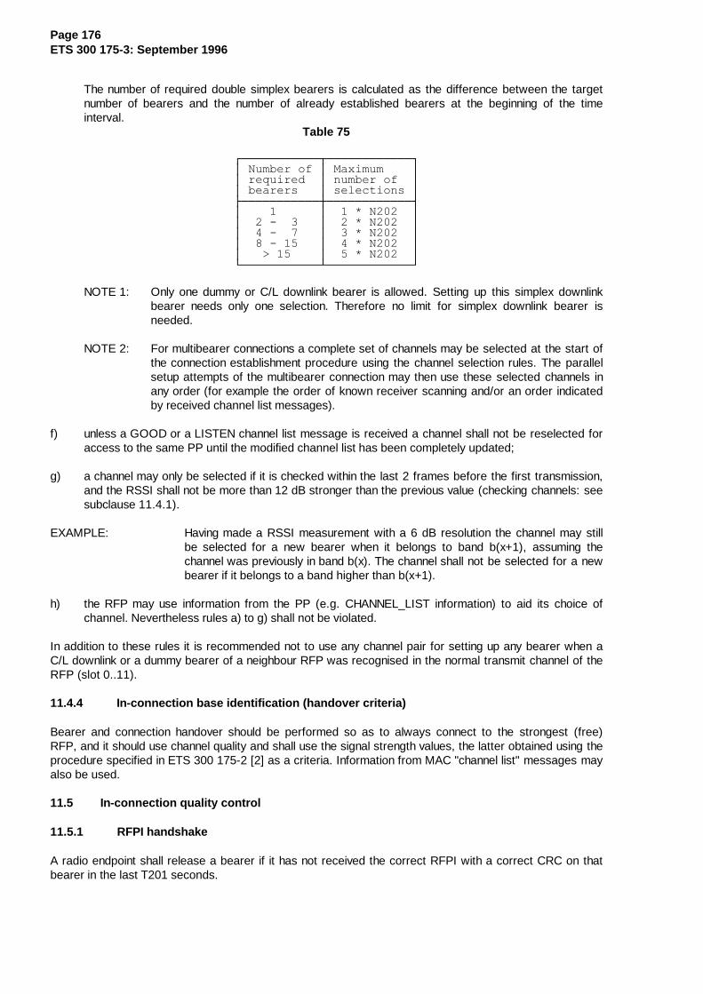
Page 176ETS 300 175-3: September 1996
The number of required double simplex bearers is calculated as the difference between the targetnumber of bearers and the number of already established bearers at the beginning of the timeinterval.
Table 75
¸¶¶¶¶¶¶¶¶¶¶¶¾¶¶¶¶¶¶¶¶¶¶¶¶¹·�1XPEHU�RI�·�0D[LPXP����··�UHTXLUHG��·�QXPEHU�RI��··�EHDUHUV���·�VHOHFWLRQV�·¼¶¶¶¶¶¶¶¶¶¶¶À¶¶¶¶¶¶¶¶¶¶¶¶½·�����������·���� �1�����··�����������·���� �1�����··�����������·���� �1�����··�����������·���� �1�����··���!�������·���� �1�����·º¶¶¶¶¶¶¶¶¶¶¶¿¶¶¶¶¶¶¶¶¶¶¶¶»
NOTE 1: Only one dummy or C/L downlink bearer is allowed. Setting up this simplex downlinkbearer needs only one selection. Therefore no limit for simplex downlink bearer isneeded.
NOTE 2: For multibearer connections a complete set of channels may be selected at the start ofthe connection establishment procedure using the channel selection rules. The parallelsetup attempts of the multibearer connection may then use these selected channels inany order (for example the order of known receiver scanning and/or an order indicatedby received channel list messages).
f) unless a GOOD or a LISTEN channel list message is received a channel shall not be reselected foraccess to the same PP until the modified channel list has been completely updated;
g) a channel may only be selected if it is checked within the last 2 frames before the first transmission,and the RSSI shall not be more than 12 dB stronger than the previous value (checking channels: seesubclause 11.4.1).
EXAMPLE: Having made a RSSI measurement with a 6 dB resolution the channel may stillbe selected for a new bearer when it belongs to band b(x+1), assuming thechannel was previously in band b(x). The channel shall not be selected for a newbearer if it belongs to a band higher than b(x+1).
h) the RFP may use information from the PP (e.g. CHANNEL_LIST information) to aid its choice ofchannel. Nevertheless rules a) to g) shall not be violated.
In addition to these rules it is recommended not to use any channel pair for setting up any bearer when aC/L downlink or a dummy bearer of a neighbour RFP was recognised in the normal transmit channel of theRFP (slot 0..11).
11.4.4 In-connection base identification (handover criteria)
Bearer and connection handover should be performed so as to always connect to the strongest (free)RFP, and it should use channel quality and shall use the signal strength values, the latter obtained using theprocedure specified in ETS 300 175-2 [2] as a criteria. Information from MAC "channel list" messages mayalso be used.
11.5 In-connection quality control
11.5.1 RFPI handshake
A radio endpoint shall release a bearer if it has not received the correct RFPI with a correct CRC on thatbearer in the last T201 seconds.
Page 177ETS 300 175-3: September 1996
11.5.2 Frequency control
11.5.2.1 RFP measurement of frequency error
Provided the RFP supports frequency control the frequency error of the received physical packets isreported in the PL_RX-cfm primitive. If the frequency error is too large (when averaged over a suitablylong time) a frequency control request is sent to the PT (see subclauses 7.2.5.5 and 7.3.5).
If the RFP receives a frequency control reject message, it shall not send any more frequency controlmessage to that PT.
11.5.2.2 PT frequency correction
When a frequency control request message is received by the MAC layer in the PT, it sends anappropriate PL_FREQ_ADJ-req primitive to its physical layer.
In response to a PL_FREQ_ADJ-req primitive the Physical layer may issue a PL_FREQ_ADJ-cfmprimitive, indicating that frequency control is not supported. A PP's MAC layer receiving this primitive maysend a frequency reject message to the requesting RFP.
11.6 Maximum allowed system load at RFPs
In any frame the maximum capacity occupied by traffic bearers at an RFP shall not exceed 14.4 half slotsper TDMA frame, multiplied by the number of RF channels available to the DECT system, as regulated bythe national authorities.
NOTE: One half slot traffic bearer occupies two half slots;one full slot traffic bearer occupies four half slot;one double slot traffic bearer occupies eight half slots.
11.7 PMID and FMID definitions
11.7.1 FMID definition
FMID is supplied to the MAC layer from the management entity.
Only one derivation is defined for the FMID:
FMID = least significant 12 bits of RFPI.
RFPI is the radio fixed part identity and is defined in ETS 300 175-6 [6].
NOTE: Each RFP of the same FP has a geographically unique FMID.
11.7.2 PMID definition
PMID is a 20 bit ID.
Two derivations for the PMID are defined. The derivation depends on whether the PT has an assignedindividual TPUI or a default TPUI. TPUI is the temporary portable subscriber identity and is defined inETS 300 175-6 [6]. The correct PMID is supplied to the portable MAC layer by the management entity.
If an assigned individual TPUI exists the PMID shall be equal to this TPUI, otherwise the PMID is derivedarbitrarily with the most significant four bits set to "1110".
NOTE: In the latter case the PMID may be set to the default TPUI.
The PMID is recalculated for every new connection setup attempt.
Page 178ETS 300 175-3: September 1996
11.8 RFP idle receiver scan sequence
In every slot a receiver in an RFP is either active , or scanning , or idling .
The receiver is active if it is receiving a traffic bearer used by that RFP.
Scanning is when the receiver is listening for bearer set up attempts on physical channels. If the receiveris active on a particular slot, it will be unable to listen in that slot on a different RF carrier (however, anRFP may have more than one receiver).
Idle is a non-preferred state. It implies that the RFP is not scanning for any (more) bearer set up attempts.Receivers are (almost automatically) idle when the RFP transmits.
All RFPs within a DECT internal handover area (see ETS 300 175-6 [6]) shall operate on the same set ofRF carriers.
The primary scan is defined as the scan that is maintained if the RFP has one or more receiver(s) free. Ifthe RFP has more than one receiver free, it maintains secondary and tertiary scans that lag behind theprimary scan .
All RFPs within a DECT internal handover area (see ETS 300 175-6 [6]) shall have their primary scans onthe same RF carrier at the same time.
If different systems are synchronised (e.g. via the synchronisation port), it is recommended that at anygiven time, the primary scans of these systems are on different RF carriers.
When RFPs scan the physical channels they shall do so in the order described below.
By the primary scan all available RF carriers shall be scanned sequentially at a rate of 1 carrier perTDMA frame. RF carriers shall be scanned in order of ascending carrier numbers.
After scanning the highest numbered available RF carrier, the receiver re-starts the primary scan in thefollowing TDMA frame on the lowest numbered available carrier.
An RFP shall listen to all slots in which a PP transmission on a new bearer can be accepted.
NOTE: An RFP of an FP that does not support asymmetric connections may be idle duringslots 0 to 11. These are the normal RFP transmit slots.
The RFP uses the QT messages to broadcast on which RF carrier its primary scan will be in the nextframe. These messages also give the number of transceivers at the RFP (thus giving an indication ofwhether a secondary or tertiary scan exists) and the number of RF carriers that exist.
Secondary receiver scan lags behind the primary receiver scan by 6 TDMA frames.
The tertiary receiver scan lags behind the primary receiver scan by 3 TDMA frames.
The operation of any additional idle receiver(s) is not defined.
Broadcast blind slot information should reflect the primary receiver scan sequence (refer tosubclause 7.2.4.3.3).
In order to optimise system performance for multiple transceiver RFPs, the RFPs should maintain activebearers in the following order of preference:
a) on any available transceiver without an active receiver scan in operation;
b) on the transceiver with the tertiary receiver scan;
c) on the transceiver with the secondary receiver scan;

Page 179ETS 300 175-3: September 1996
d) on the transceiver with the primary receiver scan.
An RFP that has an extended frequency allocation and uses one or more of the basic DECT frequenciesshall transmit "static_system_information" with a PSCN set equal to one of the basic DECT frequencies atleast once every 32 multiframes. Furthermore, the "extended_RF_carriers" message shall contain thenumber of RF carriers being scanned at that RFP.
11.9 PT fast set up receiver scan sequence
For the fast setup procedure, if the PT does not support the LISTEN message, it shall arrange its receiverscanning sequence such that it scans the same sequence of channels as the primary scan (seesubclause 11.8) at the chosen RFP. The PT scan sequence should lead the RFP (primary) scan by oneframe, as shown in figure 110.
5)3�SULPDU\�VFDQ¶¶¶¶¶¶¶¾¶¶¶¶¶¶¶¶¶¾¶¶¶¶¶¶¶¶¶¾¶¶¶¶¶¶¶¶¶¾¶¶¶¶¶¶¶¶¶¾¶¶¶¶¶¶
�·&KDQ�1���·&KDQ�1���·&KDQ�1���·���������·¶¶¶¶¶¶¿¶¶¶¶¶¶¶¶¶¿¶¶¶¶¶¶¶¶¶¿¶¶¶¶¶¶¶¶¶¿¶¶¶¶¶¶¶¶¶¿¶¶¶¶¶
�����·��������!·���7'0$�IUDPH
37�)DVW�6HWXS�6FDQ¶¶¶¶¶¶¶¾¶¶¶¶¶¶¶¶¶¾¶¶¶¶¶¶¶¶¶¾¶¶¶¶¶¶¶¶¶¾¶¶¶¶¶¶¶¶¶¾¶¶¶¶¶¶
�·&KDQ�1���·&KDQ�1���·&KDQ�1���·���������·¶¶¶¶¶¶¿¶¶¶¶¶¶¶¶¶¿¶¶¶¶¶¶¶¶¶¿¶¶¶¶¶¶¶¶¶¿¶¶¶¶¶¶¶¶¶¿¶¶¶¶¶
Figure 110
12 Medium access layer test message procedure
12.1 Introduction
For the purpose of testing, DECT equipment capable of transmitting shall recognise the set of testmessages sent by the testing system as defined in this ETS. The ability to recognise and implement thesemessages is contained in the Implementation Under Test (IUT). The response of the IUT to thesemessages is dependant on the equipment type.
DECT equipment not capable of transmitting shall not be required to recognise these messages.
NOTE: Implementation Under Test (IUT is equivalent to Equipment Under Test (EUT)).
Subclause 7.2.5.4 of this specification defines the test messages.
DECT equipment that implements only connectionless services shall not be required to implement the testmessages. However, the applicant shall declare to the test laboratory how the functions of force transmit,loopback, defeat antenna diversity and clear test modes shall be initiated.
12.2 General
The ability to recognise and implement the test messages is resident in the medium access control layer ofthe IUT. Execution of these messages are inhibited unless the IUT, in addition to the normal modeoperation, is also in the test standby mode. The test standby mode is invoked by some means of manualswitching in the IUT (e.g. dip-switch, jumper, or key-pad code as designated by the manufacturer) toprevent accidental execution of these messages in a normal DECT environment.
Receipt of a test message causes the IUT to enter the appropriate test mode(s). The IUT shall stay in thetest mode(s) indefinitely or until a "clear test modes" message is received. Receipt of this message shallclear all previously enabled test modes and return the IUT to the test standby mode (see figure 111).

Page 180ETS 300 175-3: September 1996
Figure 111: State mode diagram for IUTs during testing
After switching to the test standby mode and before the receipt of the test messages the IUT shall have noactive bearers other than the dummy bearer if the IUT is an FP.
The IUT shall be able to be switched out of the test standby mode by the same means of manual switchingas described above or by powering down the IUT. The tester should not transmit any test messagesbefore the IUT has entered the test standby mode.
No more than one test message per multiframe shall be sent to the IUT. If, however, the manufacturerdeclares to the testing authority that the IUT is able to execute test messages at a higher rate, then thetest messages shall be allowed to be sent at this higher rate.
Test messages are arranged into two groups. The first group comprises those messages which cause theIUT to enter a static mode of operation. The second group is dynamic. The IUT does not enter apermanent test mode after execution of the test message, i.e. the dynamic test message invokes atemporary test mode. These two groups are listed below:
Static Modes
a) FORCE_TRANSMIT;
b) LOOPBACK_DATA;
c) DEFEAT_ANTENNA_DIVERSITY.
Dynamic Modes
a) FORCE_BEARER_HANDOVER;
b) CLEAR_TEST_MODES.
All of the static test modes shall be able to be in operation at the same time.
The ESCAPE test message is neither static or dynamic; it serves to notify the IUT of the presence of aproprietary test message in the subsequent data bits.
Page 181ETS 300 175-3: September 1996
For a detailed description of the test procedures utilising the test messages, refer to I-ETS 300 176 [10].
12.2.1 Portable part testing
Once in the test standby mode, the IUT shall receive in at least all frames in the first half of a multiframeand all slots declared as being supported. The EUT shall execute the test message within 16 frames of thereception of the test message. Execution of the force bearer handover message shall be completed within4 multiframes.
The PP shall be able to receive and process the test messages described in subclause 7.2.5.4. The PPshall be able to receive MT tails sent on a dummy bearer in any frame allowed by the T-MUX algorithm ifno bearers currently exist.
The test message shall be sent by the LT in an MT tail using a dummy bearer if no bearers currently existotherwise they shall be sent on an existing bearer.
12.2.2 Fixed part testing
The FP shall be able to receive and process the test messages described in subclause 7.2.5.4 on a bearerthat has been initiated by the LT.
Entry into the test standby mode is from the Active_Idle or C/L state. The EUT shall execute the testmessage within 16 frames of the reception of the test message.
If there is no interference, a dummy bearer shall not change physical channels in test mode.
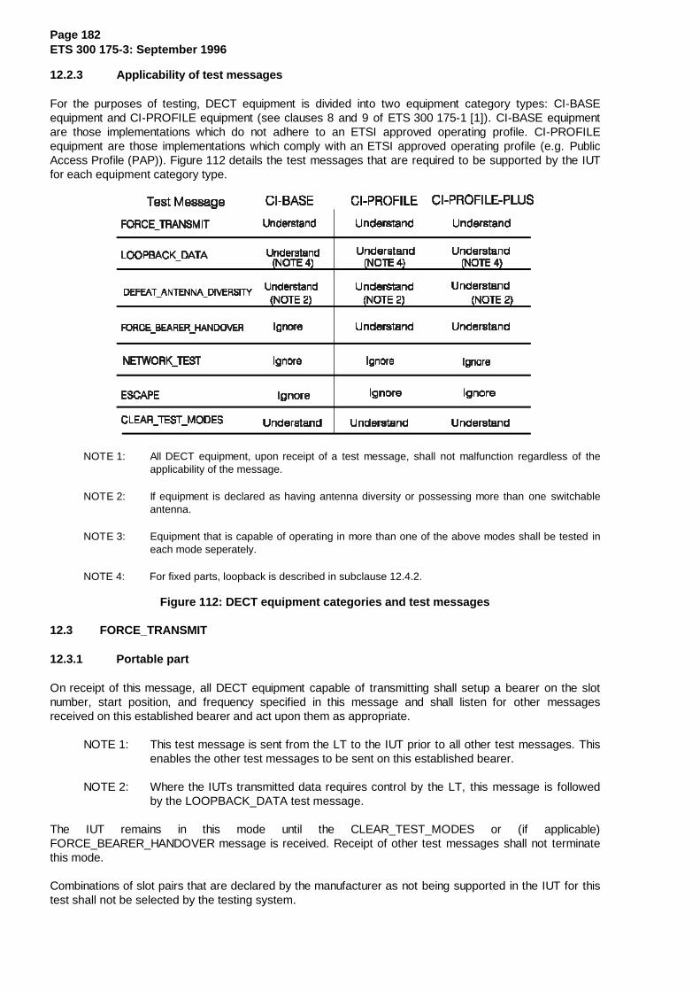
Page 182ETS 300 175-3: September 1996
12.2.3 Applicability of test messages
For the purposes of testing, DECT equipment is divided into two equipment category types: CI-BASEequipment and CI-PROFILE equipment (see clauses 8 and 9 of ETS 300 175-1 [1]). CI-BASE equipmentare those implementations which do not adhere to an ETSI approved operating profile. CI-PROFILEequipment are those implementations which comply with an ETSI approved operating profile (e.g. PublicAccess Profile (PAP)). Figure 112 details the test messages that are required to be supported by the IUTfor each equipment category type.
NOTE 1: All DECT equipment, upon receipt of a test message, shall not malfunction regardless of theapplicability of the message.
NOTE 2: If equipment is declared as having antenna diversity or possessing more than one switchableantenna.
NOTE 3: Equipment that is capable of operating in more than one of the above modes shall be tested ineach mode seperately.
NOTE 4: For fixed parts, loopback is described in subclause 12.4.2.
Figure 112: DECT equipment categories and test messages
12.3 FORCE_TRANSMIT
12.3.1 Portable part
On receipt of this message, all DECT equipment capable of transmitting shall setup a bearer on the slotnumber, start position, and frequency specified in this message and shall listen for other messagesreceived on this established bearer and act upon them as appropriate.
NOTE 1: This test message is sent from the LT to the IUT prior to all other test messages. Thisenables the other test messages to be sent on this established bearer.
NOTE 2: Where the IUTs transmitted data requires control by the LT, this message is followedby the LOOPBACK_DATA test message.
The IUT remains in this mode until the CLEAR_TEST_MODES or (if applicable)FORCE_BEARER_HANDOVER message is received. Receipt of other test messages shall not terminatethis mode.
Combinations of slot pairs that are declared by the manufacturer as not being supported in the IUT for thistest shall not be selected by the testing system.

Page 183ETS 300 175-3: September 1996
If there exists a bearer at the time the IUT receives the FORCE_TRANSMIT message, the IUT shall firstexamine the status of the "keep previous" bit to determine whether to release the current bearer. If the"keep previous" bit is set to "1", the IUT shall not release the old bearer. The IUT shall execute theappropriate setup procedure at the new slot and frequency indicated in the FORCE_TRANSMIT message.If the "keep previous" bit is set to "0", the IUT shall first release any existing bearers before performing thecall setup.
The maximum number of bearers active at any time shall not exceed the declared limit of the IUT.
NOTE 3: A manufacturer could include a multi-bearer force transmit test message as part of aproprietary test message set.
If the "handover disable" bit is set to "1" then bearer and connection handover shall be disabled (seesubclause 7.2.5.4.2).
12.3.2 Fixed part
The IUT shall allow bearer setup using any PMID while in the test standby mode. In addition, the IUT shallproceed with the bearer setup request on the slot pair on which the bearer setup request was received.
NOTE 1: The LT will initiate bearers with the IUT using the normal bearer setup proceduresdescribed in subclause 10.2, and in this way controls the transmissions of the IUT.
NOTE 2: The FORCE_TRANSMIT test message is not used when the IUT is a FP.
The IUT shall listen for other messages received on this established bearer.
The IUT remains in this mode until the CLEAR_TEST_MODES message is received. Receipt of other testmessages shall not terminate this mode.
DECT equipment utilising only the connectionless services shall not limit the number of successivetransmissions.
12.4 LOOPBACK_DATA
Loopback is that process by which data received in one slot is used to compose the data to be transmittedin the next half-frame. The sequence of the bits and their values as transmitted by the IUT is identical withthe sequence of the bits and their values as received by the IUT.
For DECT equipment capable of setting up a bearer, the IUT must have a bearer existing before thismessage can be executed by the IUT. If no bearer exists when the test message is transmitted by thetester, the IUT shall ignore this message.
DECT equipment utilising only A-field transmissions shall loopback bits a16 to a47 of the A-field. The IUTshall not limit the number of successive transmissions.
DECT equipment capable of B-field transmission shall loopback bits b0 to b79 for half-slot implementationsor bits b0 to b319 for full-slot implementations. Equipment supporting both half- and full-slot operation shallloopback bits b0 to b319. The A-field loopback shall not be used.
DECT equipment capable of transmitting double-slots shall loopback bits b0 to b799. Equipment supportinghalf- and/or full-slots in addition to the double-slot shall loopback bits b0 to b799. The A-field loopback shallnot be used.

Page 184ETS 300 175-3: September 1996
12.4.1 Portable part
The point at which loopback occurs in the MAC of the IUT can be above or below the scrambling functionsof the IUT.
If a FORCE_BEARER_HANDOVER message is received after receipt of the LOOPBACK_DATAmessage, the IUT shall continue to operate in the loopback mode after execution of the bearer handoverprocedure. The IUT may transmit the loopback data on both bearers during execution of its bearerhandover procedure. The IUT shall continue to operate in the loopback mode until receipt of theCLEAR_TEST_MODES or power down of the unit.
12.4.2 Fixed Part
12.4.2.1 IUTs implementing the DECT scrambler
The point of loopback in the MAC of the IUT may occur above and below any scrambling functions of theIUT.
12.4.2.2 IUTs implementing a proprietary scrambler
The point of loopback in the MAC of the IUT shall occur below any scrambling functions of the IUT.
NOTE: "Below" means without passing through the scrambling functions of the IUT.
12.5 DEFEAT_ANTENNA_DIVERSITY
All equipment equipped with antenna diversity shall respond to this message. The antenna selected by thismessage shall be used for both receive and transmit. The IUT stays on the selected antenna until a newantenna is selected or the "clear test modes" message is received.
12.6 FORCE_BEARER_HANDOVER
This message is recognised only by CI-PROFILE equipment capable of transmitting a traffic bearer. TheIUT must have a duplex bearer existing before this message is executed. If there are no duplex bearer(s)between the IUT and testing system at the time of reception of this message, the IUT shall ignore thismessage.
12.7 NETWORK_TEST
This message is used to invoke testing procedures resident in the network layer. The 32 bit SDU is passedthrough the ME SAP to the LLME. No further action is requiredAll implementations shall recognise thenetwork test message, however, IUTs not implementing this method to invoke testing procedures shallignore the network test message.
12.8 ESCAPE
Proprietary test messages resident in an IUT shall be declared by the manufacturer to the testing authoritybefore testing may begin. Any transmission of a proprietary test message shall be preceded by theESCAPE message in the same transmission. Proprietary test message(s) shall occupy bit positions a16 toa47 of the A-field. All implementations shall recognise the ESCAPE test message, however, EUTs notimplementing proprietary test message(s) shall ignore the ESCAPE message.
12.9 CLEAR_TEST_MODES
The CLEAR_TEST_MODES message is used as a "reset" function. It's purpose is to force the IUT back tothe test standby mode. Receipt of this message shall clear all previously enabled static test modes(including static proprietary modes) within 16 frames and return the IUT to the test standby mode.
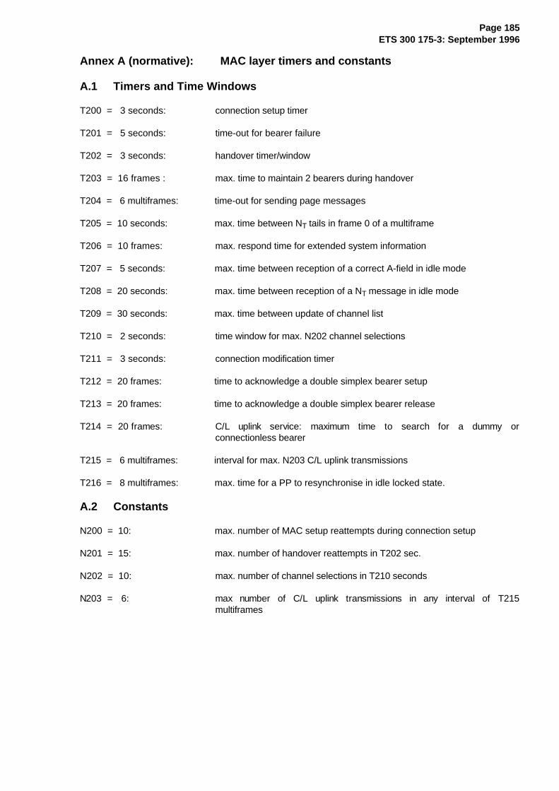
Page 185ETS 300 175-3: September 1996
Annex A (normative): MAC layer timers and constants
A.1 Timers and Time Windows
T200 = 3 seconds: connection setup timer
T201 = 5 seconds: time-out for bearer failure
T202 = 3 seconds: handover timer/window
T203 = 16 frames : max. time to maintain 2 bearers during handover
T204 = 6 multiframes: time-out for sending page messages
T205 = 10 seconds: max. time between NT tails in frame 0 of a multiframe
T206 = 10 frames: max. respond time for extended system information
T207 = 5 seconds: max. time between reception of a correct A-field in idle mode
T208 = 20 seconds: max. time between reception of a NT message in idle mode
T209 = 30 seconds: max. time between update of channel list
T210 = 2 seconds: time window for max. N202 channel selections
T211 = 3 seconds: connection modification timer
T212 = 20 frames: time to acknowledge a double simplex bearer setup
T213 = 20 frames: time to acknowledge a double simplex bearer release
T214 = 20 frames: C/L uplink service: maximum time to search for a dummy orconnectionless bearer
T215 = 6 multiframes: interval for max. N203 C/L uplink transmissions
T216 = 8 multiframes: max. time for a PP to resynchronise in idle locked state.
A.2 Constants
N200 = 10: max. number of MAC setup reattempts during connection setup
N201 = 15: max. number of handover reattempts in T202 sec.
N202 = 10: max. number of channel selections in T210 seconds
N203 = 6: max number of C/L uplink transmissions in any interval of T215multiframes

Page 186ETS 300 175-3: September 1996
Annex B (informative): Construct ion of the CRC polynomial and errordetecting performance
The factorisation of the polynomial g(x) results in:
g(x) = M7(13)(x) * M7(29)(x) * (x+1)2;
202'611 = 203 * 253 * (3)2 (octal).
M7(i)(x) denotes the minimal polynomial of αi where α is the primitive element of GF(27) used in AppendixC of Peterson and Weldon "Error correcting codes" [20].
The product of M7(13)(x) * M7
(29)(x) results in a generator polynomial for a primitive binary (127,113) BCHcode with minimum Hamming distance of 5. Multiplying this polynomial with (x+1)2 gives the generatorpolynomial g(x). For different data block lengths n the minimum Hamming distance dmin for the (m,n) blockcode generated with g(x) is given in table B.1.
Table B.1
¸¶¶¶¶¶¶¶¶¶¾¶¶¶¶¶¶¶¶¶¶¶¶¶¹·��GPLQ���·�P� �Q�������·¼¶¶¶¶¶¶¶¶¶À¶¶¶¶¶¶¶¶¶¶¶¶¶½·���������·�������������··���������·�������������··���������·�������������·º¶¶¶¶¶¶¶¶¶¿¶¶¶¶¶¶¶¶¶¶¶¶¶»
The polynomial g(x) has the minimum number of non zero coefficients for codes with dmin = 6.
For 17 ≤ m ≤ 128 the resulting (m,n) block code provides the following error detection properties:
- detect all odd number of errors;
- any error pattern with less than 6 errors; and
- any error-burst up to length 16.
Because a BCH code is included, up to double error correcting may be applied.

Page 187ETS 300 175-3: September 1996
Annex C (informative): MAC relationship to other layers
A complete DECT fixed radio termination may contain several independent cells, where each cell containsone independent physical layer instance (independent radio transceivers).
The MAC layer provides an intermediate level of grouping between these distributed physical layers andthe single (central) instance of the higher layers. This intermediate grouping is termed a (MAC) cluster,where one cluster represents a single MAC layer instance. A complete FT may thereby contain two levelsof hierarchy:
- one FT may contain multiple independent MAC clusters (MAC layer instances);
- each cluster may control multiple independent PHL cells (physical layer instances).
�·�����·�¸¶¶¶¶¿¶¶¶¶¶¿¶¶¶¶¹�·��&HQWUDO�)7���·�·���HOHPHQWV����·�·�KLJKHU�OD\HUV�·�º¶¶¾¶¶¶¶¾¶¶¶¶¾¶¶»
�¸¶¶¶¶¶¶¶¶¶¶¶¶»����·����º¶¶¶¶¶¶¶¶¶¶¶¶¹¸¶¶¶¶¶¿¶¶¶¶¹������¸¶¶¶¶¶¿¶¶¶¶¹������¸¶¶¶¶¶¿¶¶¶¶¹·���0$&����·������·���0$&����·������·���0$&����··�FOXVWHU��·������·�FOXVWHU��·������·�FOXVWHU��·º¶¶¾¶¶¾¶¶¾¶»������º¶¶¾¶¶¾¶¶¾¶»������º¶¶¾¶¶¾¶¶¾¶»�¸¶¶»��·��º¶¶¹�����¸¶¶»��·��º¶¶¹�����¸¶¶»��·��º¶¶¹
¸¶¶¿¶¹¸¶¶¿¶¹¸¶¶¿¶¹¸¶¶¿¶¹¸¶¶¿¶¹¸¶¶¿¶¹¸¶¶¿¶¹¸¶¶¿¶¹¸¶¶¿¶¹·3+/�··3+/�··3+/�··3+/�··3+/�··3+/�··3+/�··3+/�··3+/�··FHOO··FHOO··FHOO··FHOO··FHOO··FHOO··FHOO··FHOO··FHOO·º¶¶¶¶»º¶¶¶¶»º¶¶¶¶»º¶¶¶¶»º¶¶¶¶»º¶¶¶¶»º¶¶¶¶»º¶¶¶¶»º¶¶¶¶»
NOTE: This divisions in this picture do not correspond to physical boundaries.
Figure C.1: FT with multiple MAC clusters
The independent lower instances of MAC and PHL are all accessed via independent sets of service accesspoints. The MAC functional groupings correspond to these independent SAPs.
The single instance of MAC cluster control functions relate to the single set of upper SAPs.
The multiple instances of MAC cell site functions relate to the multiple instances of lower SAPs. (There isone CSF for each PHL cell belonging to the cluster).

Page 188ETS 300 175-3: September 1996
Annex D (informative): Synchronisation
The MAC layer, in combination with the physical layer provides synchronisation between fixed radiotermination and portable radio terminations. In all cases, the FT is the timing master, and a PT is alwaysrequired to synchronise to an FT before it can obtain service.
Three types of synchronisation are defined:
- slot synchronisation; refer to ETS 300 175-2 [2];
- frame synchronisation; refer to ETS 300 175-2 [2];
- multiframe synchronisation; refer to subclause 4.2.3.
Synchronisation of a PT is achieved and maintained by the reception of physical packets by the physicallayer for any active slots. This provides the first level of timing. A small number of messages are then usedin the Q logical channel to define frame synchronisation and multiframe synchronisation relative to this slottiming. This process is defined in subclause 6.2.2.1.
The FT transmissions are required to be frame and multi-frame synchronised at all RFPs in any onecluster. It is required that this synchronisation is maintained across a complete fixed radio termination.
At the PT, successful synchronisation is required for the PT to "lock" to the transmissions of an FT. A PTcan exist in one of three synchronisation states at the MAC layer:
1) Unlocked: the PT is not synchronised to any RFP;
2) Lock_pending: the PT is receiving RFP transmissions, but has not yet obtained frame and/ormultiframe synchronisation;
3) Locked: the PT has achieved frame and multi-frame lock to an RFP.

Page 189ETS 300 175-3: September 1996
Annex E (informative): Scrambling patterns
Table E.1 lists the first 16 bits and the last 2 bits (for both full and half slots) of the scrambling bitsequence that shall be used each frame.
The sequence repeats every 8 frames, so the sequence is the same for frames 0 and 8, and for frames 1and 9, etc.
Table E.1
����������¸¶¶¶¶¶¶¶¶¶¶¶¶¶¶¶¶¶¶¶¶¶¶¶¶¶¶¶¶¶¶¶¹����������·���)5$0(�180%(56���������������·¸¶¶¶¶¶¶¶¶¹¼¶¶¶¾¶¶¶¾¶¶¶¾¶¶¶¾¶¶¶¾¶¶¶¾¶¶¶¾¶¶¶½·�%,7����··���·���·���·���·���·���·���·���··�180%(5�··���·���·���·���·���·���·���·���·¼¶¶¶¶¶¶¶¶ÀÀ¶¶¶À¶¶¶À¶¶¶À¶¶¶À¶¶¶À¶¶¶À¶¶¶À¶¶¶½·���E����··���·���·���·���·���·���·���·���··���E����··���·���·���·���·���·���·���·���··���E����··���·���·���·���·���·���·���·���··���E����··���·���·���·���·���·���·���·���··���E����··���·���·���·���·���·���·���·���··���E����··���·���·���·���·���·���·���·���··���E����··���·���·���·���·���·���·���·���··���E����··���·���·���·���·���·���·���·���··���E����··���·���·���·���·���·���·���·���··���E����··���·���·���·���·���·���·���·���··���E����··���·���·���·���·���·���·���·���··���E����··���·���·���·���·���·���·���·���··���E����··���·���·���·���·���·���·���·���··���E����··���·���·���·���·���·���·���·���··���E����··���·���·���·���·���·���·���·���··���E����··���·���·���·���·���·���·���·���··��������··���·���·���·���·���·���·���·���··��HWF���··���·���·���·���·���·���·���·���··��������··���·���·���·���·���·���·���·���··���E����··���·���·���·���·���·���·���·���··���E����··���·���·���·���·���·���·���·���··��������··���·���·���·���·���·���·���·���··��HWF���··���·���·���·���·���·���·���·���··��������··���·���·���·���·���·���·���·���··��E�����··���·���·���·���·���·���·���·���··��E�����··���·���·���·���·���·���·���·���··��E�����··���·���·���·���·���·���·���·���·º¶¶¶¶¶¶¶¶¿¿¶¶¶¿¶¶¶¿¶¶¶¿¶¶¶¿¶¶¶¿¶¶¶¿¶¶¶¿¶¶¶»
Page 190ETS 300 175-3: September 1996
Annex F (informative): P ublic Access Profile (PAP): mandatory re quirementsregarding the MAC layer
This annex is a reprint of clause 8 of ETS 300 175-9 [9] and contains the elements specified in this part ofthe standard. In the event of any conflict between this annex and ETS 300 175-9 [9], the text inETS 300 175-9 [9] shall be the prime source (i.e. ETS 300 175-9 [9] is normative).
Public access equipment shall provide at least all of the elements stated below.
F.1 MAC layer services
F.1.1 Connection oriented services
The FT and PT shall support basic connections, these are from service type 1f (IN_minimum_delay). Atleast the B-field multiplex type U32a shall be supported.
F.1.2 Broadcast services
The FT shall support the continuous broadcast service.
F.2 MAC layer procedures
F.2.1 Connection oriented service procedures
F.2.1.1 General
The FT and PT shall support the basic connection set-up procedure and the A-field connection releaseprocedure.
NOTE 1: The basic set-up procedure creates a basic connection.
The PT shall support the duplex bearer handover procedure and the connection handover procedure. If theFT does not support the connection handover procedure for intra-cell handover, the FT shall support theduplex bearer handover procedure.
NOTE 2: Support of the connection handover procedure requires the MAC to support additionalmessages as defined in subclause F.4.2.4.
F.2.1.2 Antenna diversity in connection oriented services
F.2.1.2.1 Q1 setting in direction PT to FT
The PT shall set Q1 = 1 in the next associated transmission when the quality of the received burst isdetermined to be poor. The determination of the received quality may be based on the following:
a) results of the A and X-CRCs;
b) conditions of the S and Z fields;
c) radio signal strength;
d) other appropriate parameters.
The Q1 bit is defined in the A-field header message, refer to this ETS.
S- and Z-field failure are defined as in ETS 300 175-2 [2]. A-CRC and X-CRC are defined in this ETS.

Page 191ETS 300 175-3: September 1996
F.2.1.2.2 Antenna change due to FT reception of Q1
If antenna diversity is implemented, the RFP shall, on reception of Q1 = 1, change antenna for nextassociated RFP transmission unless the RFP has knowledge of the optimum downlink transmissionantenna obtained from simultaneous measurements of the last PT transmission as per subclause 8.3 ofETS 300 175-2 [2] on all provided antennas.
If Q1 = 0 is received by the RFP in the next associated slot, the antenna should also be changed for theassociated receive direction.
F.2.1.2.3 Antenna change due to poor quality on slot received at FT
If antenna diversity is implemented, the RFP shall, when the quality of the received burst is poor, changeantenna. The determination of the received quality may be based on the following:
a) results of the A and X-CRCs;
b) conditions of the S and Z fields;
c) radio signal strength;
d) other appropriate parameters.
S- and Z-field failure are defined as in ETS 300 175-2 [2]. A-CRC and X-CRC are defined in this ETS.
If the next associated slot is received error free by the RFP, the antenna should also be changed for theassociated transmit direction.
F.2.1.3 Information for handover
F.2.1.3.1 Q1 and Q2 setting in direction FT to PT
Q1 and Q2 shall be used in accordance with this ETS. The Q2 bit shall be set according to A-field andB-field acceptance. The minimum criteria for B-field data rejection as defined in this ETS is X-CRC failure.It is also mandated to set Q1 on sliding collision information if Q2 = 1, and on A-CRC result if Q2 = 0.Sliding collision is defined in ETS 300 175-2 [2] annex B.
The Q1 bit and the Q2 bit are defined in the A-field header message, refer to this ETS.
F.2.1.3.2 PT reception of Q1 and Q2
The PT should use Q1 and Q2 information for making the handover decision.
F.2.2 Broadcast procedures
At least the following downlink broadcast procedures shall be supported by the FT:
- broadcast of NT messages (see subclause F.4.2.1);
- broadcast of mandatory QT messages (see subclause F.4.2.2).
F.3 Scrambling
Scrambling of the B field as specified in this ETS is mandatory.

Page 192ETS 300 175-3: September 1996
F.4 Required messages
F.4.1 Header field
The FT and PT shall understand all tail identifications.
The FT and PT shall be able to send at least the tail identifications code given in table F.1.
Table F.1
¸¶¶¶¶¶¶¶¶¶¾¶¶¶¶¶¶¶¶¶¶¶¶¶¶¶¶¶¶¶¶¶¶¶¶¶¶¶¶¶¾¶¶¶¶¶¶¶¶¶¶¶¶¶¶¹·D��D��D��·�������7DLO�FRQWHQWV���������·�5HVWULFWLRQV�·¼¶¶¶¶¶¶¶¶¶À¶¶¶¶¶¶¶¶¶¶¶¶¶¶¶¶¶¶¶¶¶¶¶¶¶¶¶¶¶À¶¶¶¶¶¶¶¶¶¶¶¶¶¶½·���������·�&T�GDWD�SDFNHW�QXPEHU�������·��������������··���������·�����������������������������·��������������··���������·�&T�GDWD�SDFNHW�QXPEHU�������·��������������··���������·�����������������������������·��������������··���������·�LGHQWLWLHV�LQIRUPDWLRQ��1T��·��������������··���������·�����������������������������·��������������··���������·�PXOWLIUDPH�V\QFKURQLVDWLRQ��·���5)3�RQO\���··���������·�DQG�V\VWHP�LQIRUPDWLRQ��4T��·��������������··���������·�����������������������������·��������������··���������·�0$&�OD\HU�FRQWURO��0T�������·��������������··���������·�����������������������������·��������������··���������·�ILUVW�&33�WUDQVPLVVLRQ��0T��·���33�RQO\����·¼¶¶¶¶¶¶¶¶¶¿¶¶¶¶¶¶¶¶¶¶¶¶¶¶¶¶¶¶¶¶¶¶¶¶¶¶¶¶¶¿¶¶¶¶¶¶¶¶¶¶¶¶¶¶½·��������5)3�RQO\��PHDQV�5)3�WUDQVPLVVLRQV�RQO\��������··��������33�RQO\��PHDQV�33�WUDQVPLVVLRQV�RQO\����������·º¶¶¶¶¶¶¶¶¶¶¶¶¶¶¶¶¶¶¶¶¶¶¶¶¶¶¶¶¶¶¶¶¶¶¶¶¶¶¶¶¶¶¶¶¶¶¶¶¶¶¶¶¶¶»
The FT shall react correctly to the B field identification for "U type, IN" and shall be able to send the B fieldidentifications for "U type, IN" and "no B-field".
The PT shall react correctly to the B field identifications for "U type, IN" and "no B-field" and shall be ableto send the B field identification for "U type, IN".
The FT and PT shall be able to send and shall react correctly to the Q1 and Q2 bits using the proceduresdefined in subclauses F.2.1.2 and F.2.1.3.
F.4.2 Messages in the tail field
F.4.2.1 Identities information (N T tail)
PT and FT shall be able to send, and shall react correctly to the NT tail.
F.4.2.2 System information and multiframe marker (Q T tail)
The FT shall be able to send and the PT shall understand at least the QT messages given in table F.2.
Table F.2
¸¶¶¶¶¶¶¾¶¶¶¶¶¶¶¶¶¶¶¶¶¶¶¶¶¶¶¶¶¶¶¶¶¶¶¶¶¶¶¶¶¶¶¶¶¶¶¾¶¶¶¶¶¶¶¶¾¶¶¶¶¶¶¹·��4H��·�6\VWHP�,QIRUPDWLRQ��������������������·��0DQ���·�)UHT�·¼¶¶¶¶¶¶À¶¶¶¶¶¶¶¶¶¶¶¶¶¶¶¶¶¶¶¶¶¶¶¶¶¶¶¶¶¶¶¶¶¶¶¶¶¶¶À¶¶¶¶¶¶¶¶À¶¶¶¶¶¶½·����;�·�VWDWLF�V\VWHP�LQIR��������������������·��<HV���·������··������·�H[WHQGHG�5F�FDUULHUV������������������·��QRWH��·������··������·�IL[HG�SDUW�FDSDELOLWLHV���������������·��<HV���·������··������·�6$5,�OLVW�FRQWHQWV��������������������·��1R����·������·¼¶¶¶¶¶¶¿¶¶¶¶¶¶¶¶¶¶¶¶¶¶¶¶¶¶¶¶¶¶¶¶¶¶¶¶¶¶¶¶¶¶¶¶¶¶¶¿¶¶¶¶¶¶¶¶¿¶¶¶¶¶¶½·�0DQ���0DQGDWRU\�WUDQVPLVVLRQ��<HV�1R�������������������������··�)UHT��0D[LPXP�UHSHDW�LQWHUYDO�LQ�PXOWLIUDPHV��LI�LPSOHPHQWHG�··��������������������������������������������������������������··�127(��7UDQVPLVVLRQ�RI�WKH��([WHQGHG�5F�FDUULHUV��PHVVDJH�LV��··�������RQO\�PDQGDWHG�IRU�)3V�WKDW�VXSSRUW�H[WHQGHG�5F�FDUULHU�··�������RSHUDWLRQ����������������������������������������������·º¶¶¶¶¶¶¶¶¶¶¶¶¶¶¶¶¶¶¶¶¶¶¶¶¶¶¶¶¶¶¶¶¶¶¶¶¶¶¶¶¶¶¶¶¶¶¶¶¶¶¶¶¶¶¶¶¶¶¶¶¶¶»

Page 193ETS 300 175-3: September 1996
F.4.2.3 Paging (P T tail)
The transmission and understanding of paging messages is not required for the minimum public accessprofile.
F.4.2.4 MAC control (M T tails)
PT and FT shall be able to send and shall react correctly to the following groups of messages:
- the basic connection control messages (note 1);
- MAC test messages (note 2).
NOTE 1: The "Unconfirmed_access_request" message shall not be used for a basic connection.
NOTE 2: Equipment shall only respond to MAC test messages when operating in the"Test-Standby-Mode". Refer to I-ETS 300 176 [10].
F.4.3 Messages in the B-field
No operations that require transmission or response to B-field messages is required for the minimum publicaccess profile.
NOTE: Equipment shall understand the tail code associated with B-field messages as definedin subclause F.4.1. Received B-field messages should be discarded if they cannot beunderstood.
F.5 Monitoring of speech quality
The X-CRC information from received slot with IN data should be used to support monitoring of receivedspeech quality.
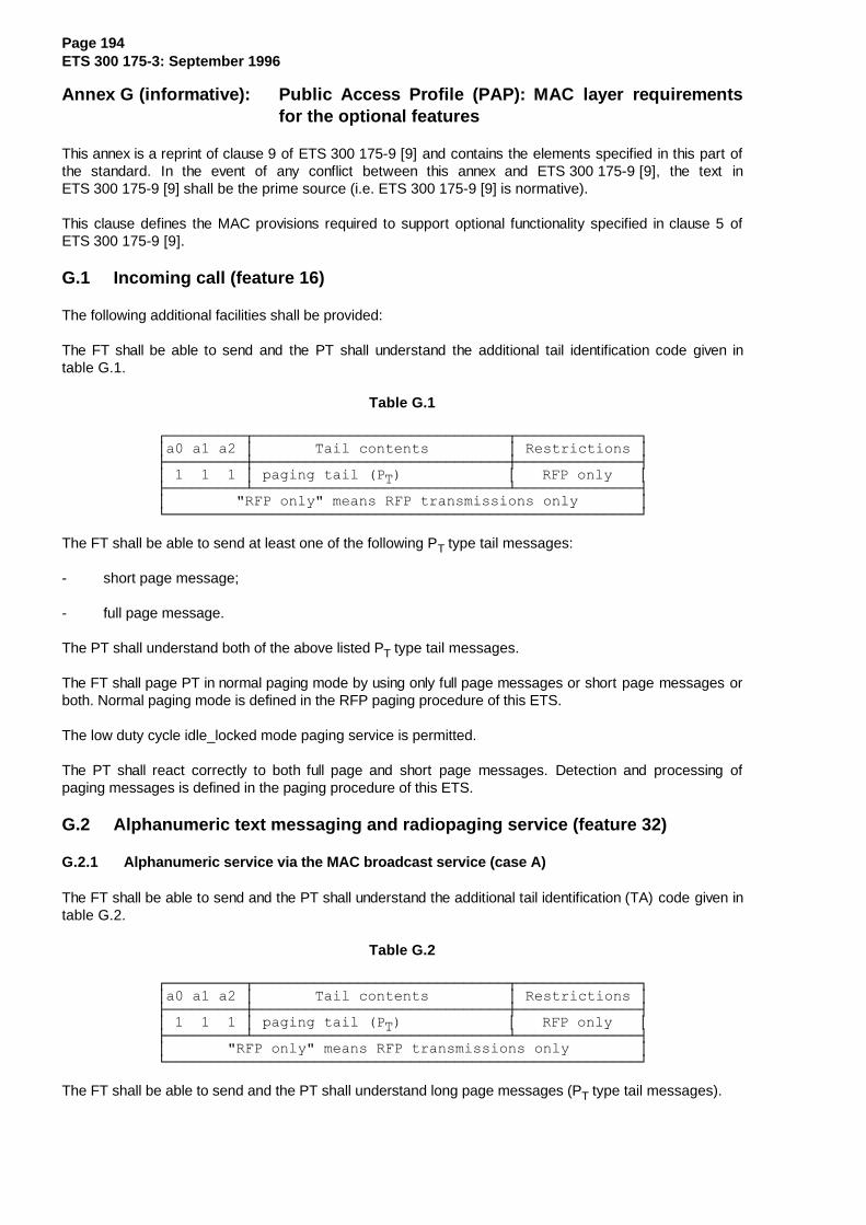
Page 194ETS 300 175-3: September 1996
Annex G (informative): P ublic Access Profile (PAP): MAC layer re quirementsfor the optional features
This annex is a reprint of clause 9 of ETS 300 175-9 [9] and contains the elements specified in this part ofthe standard. In the event of any conflict between this annex and ETS 300 175-9 [9], the text inETS 300 175-9 [9] shall be the prime source (i.e. ETS 300 175-9 [9] is normative).
This clause defines the MAC provisions required to support optional functionality specified in clause 5 ofETS 300 175-9 [9].
G.1 Incoming call (feature 16)
The following additional facilities shall be provided:
The FT shall be able to send and the PT shall understand the additional tail identification code given intable G.1.
Table G.1
¸¶¶¶¶¶¶¶¶¶¾¶¶¶¶¶¶¶¶¶¶¶¶¶¶¶¶¶¶¶¶¶¶¶¶¶¶¶¶¶¾¶¶¶¶¶¶¶¶¶¶¶¶¶¶¹·D��D��D��·�������7DLO�FRQWHQWV���������·�5HVWULFWLRQV�·¼¶¶¶¶¶¶¶¶¶À¶¶¶¶¶¶¶¶¶¶¶¶¶¶¶¶¶¶¶¶¶¶¶¶¶¶¶¶¶À¶¶¶¶¶¶¶¶¶¶¶¶¶¶½·���������·�SDJLQJ�WDLO��37�������������·���5)3�RQO\���·¼¶¶¶¶¶¶¶¶¶¿¶¶¶¶¶¶¶¶¶¶¶¶¶¶¶¶¶¶¶¶¶¶¶¶¶¶¶¶¶¿¶¶¶¶¶¶¶¶¶¶¶¶¶¶½·���������5)3�RQO\��PHDQV�5)3�WUDQVPLVVLRQV�RQO\�������·º¶¶¶¶¶¶¶¶¶¶¶¶¶¶¶¶¶¶¶¶¶¶¶¶¶¶¶¶¶¶¶¶¶¶¶¶¶¶¶¶¶¶¶¶¶¶¶¶¶¶¶¶¶¶»
The FT shall be able to send at least one of the following PT type tail messages:
- short page message;
- full page message.
The PT shall understand both of the above listed PT type tail messages.
The FT shall page PT in normal paging mode by using only full page messages or short page messages orboth. Normal paging mode is defined in the RFP paging procedure of this ETS.
The low duty cycle idle_locked mode paging service is permitted.
The PT shall react correctly to both full page and short page messages. Detection and processing ofpaging messages is defined in the paging procedure of this ETS.
G.2 Alphanumeric text messaging and radiopaging service (feature 32)
G.2.1 Alphanumeric service via the MAC broadcast service (case A)
The FT shall be able to send and the PT shall understand the additional tail identification (TA) code given intable G.2.
Table G.2
¸¶¶¶¶¶¶¶¶¶¾¶¶¶¶¶¶¶¶¶¶¶¶¶¶¶¶¶¶¶¶¶¶¶¶¶¶¶¶¶¾¶¶¶¶¶¶¶¶¶¶¶¶¶¶¹·D��D��D��·�������7DLO�FRQWHQWV���������·�5HVWULFWLRQV�·¼¶¶¶¶¶¶¶¶¶À¶¶¶¶¶¶¶¶¶¶¶¶¶¶¶¶¶¶¶¶¶¶¶¶¶¶¶¶¶À¶¶¶¶¶¶¶¶¶¶¶¶¶¶½·���������·�SDJLQJ�WDLO��37�������������·���5)3�RQO\���·¼¶¶¶¶¶¶¶¶¶¿¶¶¶¶¶¶¶¶¶¶¶¶¶¶¶¶¶¶¶¶¶¶¶¶¶¶¶¶¶¿¶¶¶¶¶¶¶¶¶¶¶¶¶¶½·��������5)3�RQO\��PHDQV�5)3�WUDQVPLVVLRQV�RQO\��������·º¶¶¶¶¶¶¶¶¶¶¶¶¶¶¶¶¶¶¶¶¶¶¶¶¶¶¶¶¶¶¶¶¶¶¶¶¶¶¶¶¶¶¶¶¶¶¶¶¶¶¶¶¶¶»
The FT shall be able to send and the PT shall understand long page messages (PT type tail messages).

Page 195ETS 300 175-3: September 1996
For the alphanumeric service the FT shall only use long page messages in normal paging mode. Thispaging mode is defined in the RFP paging procedure of this ETS.
The PT shall react correctly to long page messages. Detection and processing of paging messages isdefined in the paging procedure of this ETS.
G.2.2 Alphanumeric service via the MAC C/L downlink service (case B1)
FT and PT shall support the requirements for incoming calls as defined in clause G.1.
FT and PT shall support the CLF channel. To transmit or receive CLF channel data the multiplex E32 shallbe supported.
The FT shall be able to transmit, and the PT shall understand the coding of the TA field of the A-fieldheader given in table G.3.
Table G.3
¸¶¶¶¶¶¶¶¶¶¾¶¶¶¶¶¶¶¶¶¶¶¶¶¶¶¶¶¶¶¶¶¶¶¶¶¶¶¶¶¾¶¶¶¶¶¶¶¶¶¶¶¶¶¶¹·D��D��D��·�������7DLO�FRQWHQWV���������·�5HVWULFWLRQV�·¼¶¶¶¶¶¶¶¶¶À¶¶¶¶¶¶¶¶¶¶¶¶¶¶¶¶¶¶¶¶¶¶¶¶¶¶¶¶¶À¶¶¶¶¶¶¶¶¶¶¶¶¶¶½·���������·�LGHQWLWLHV�LQIRUPDWLRQ��17��·���5)3�RQO\���··���������·�RQ�FRQQHFWLRQOHVV�EHDUHU����·��������������·¼¶¶¶¶¶¶¶¶¶¿¶¶¶¶¶¶¶¶¶¶¶¶¶¶¶¶¶¶¶¶¶¶¶¶¶¶¶¶¶¿¶¶¶¶¶¶¶¶¶¶¶¶¶¶½·���������5)3�RQO\��PHDQV�5)3�WUDQVPLVVLRQV�RQO\�������·º¶¶¶¶¶¶¶¶¶¶¶¶¶¶¶¶¶¶¶¶¶¶¶¶¶¶¶¶¶¶¶¶¶¶¶¶¶¶¶¶¶¶¶¶¶¶¶¶¶¶¶¶¶¶»
Additional B-field identification codes in the A-field header are used for the C/L downlink service. These aregiven in table G.4.
Table G.4
¸¶¶¶¶¶¶¶¶¶¾¶¶¶¶¶¶¶¶¶¶¶¶¶¶¶¶¶¶¶¶¶¶¶¶¶¶¶¶¶¶¶¶¶¶¶¶¶¶¹·D��D��D��·���������%�ILHOG�FRQWHQWV�������������·¼¶¶¶¶¶¶¶¶¶À¶¶¶¶¶¶¶¶¶¶¶¶¶¶¶¶¶¶¶¶¶¶¶¶¶¶¶¶¶¶¶¶¶¶¶¶¶¶½·���������·�(�W\SH��DOO�&/)����������������������··���������·��������������������������������������··���������·�(�W\SH��QRW�DOO�&/)������������������··���������·��������������������������������������··���������·�(�W\SH��DOO�0$&�FRQWURO��XQQXPEHUHG��·º¶¶¶¶¶¶¶¶¶¿¶¶¶¶¶¶¶¶¶¶¶¶¶¶¶¶¶¶¶¶¶¶¶¶¶¶¶¶¶¶¶¶¶¶¶¶¶¶»
The FT shall be able to transmit and the PT shall understand these additional BA codes.
The FT shall be able to transmit and the PT shall understand the MAC B-field "null" message.
The FT and PT shall support the downlink connectionless procedure as defined in this ETS.
G.2.3 Alphanumeric service via the MAC C/L downlink and uplink services (case B2)
FT and PT shall support the requirements for the alphanumeric service via the MAC C/L downlink serviceas defined in subclause G.2.2.
The FT shall support the CF channel.
NOTE: Even though this channel is not used by basic connections the PT decides on the CFcapability indication in the fixed part capabilities message (see subclause F.4.2.2) if theCLF channel is available (see C/L uplink procedure in this ETS.
The PT shall be able to transmit and the FT shall understand the additional B-field identification codesdefined in subclause G.2.2.
The PT shall be able to transmit and the FT shall understand the subset of the broadcast andconnectionless service MT tail messages given in table G.5.
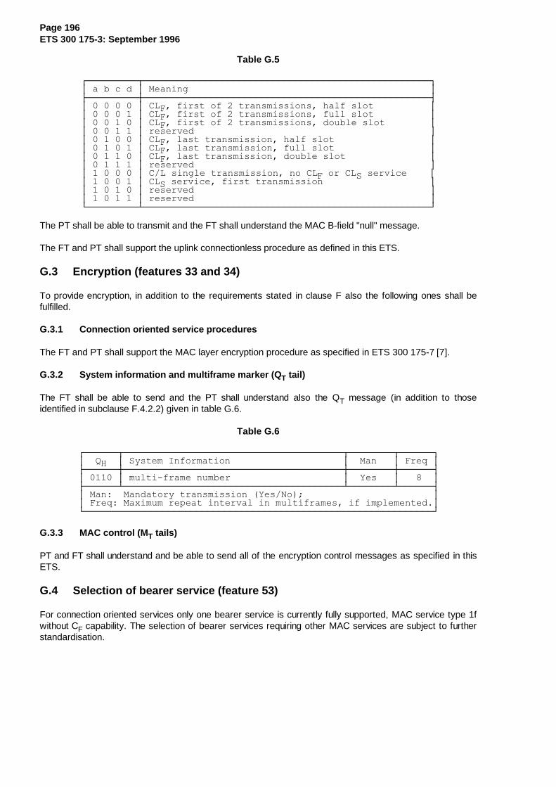
Page 196ETS 300 175-3: September 1996
Table G.5
¸¶¶¶¶¶¶¶¶¶¾¶¶¶¶¶¶¶¶¶¶¶¶¶¶¶¶¶¶¶¶¶¶¶¶¶¶¶¶¶¶¶¶¶¶¶¶¶¶¶¶¶¶¶¶¶¶¶¶¶¶¶¹·�D�E�F�G�·�0HDQLQJ�������������������������������������������·¼¶¶¶¶¶¶¶¶¶À¶¶¶¶¶¶¶¶¶¶¶¶¶¶¶¶¶¶¶¶¶¶¶¶¶¶¶¶¶¶¶¶¶¶¶¶¶¶¶¶¶¶¶¶¶¶¶¶¶¶¶½·���������·�&/)��ILUVW�RI���WUDQVPLVVLRQV��KDOI�VORW����������··���������·�&/)��ILUVW�RI���WUDQVPLVVLRQV��IXOO�VORW����������··���������·�&/)��ILUVW�RI���WUDQVPLVVLRQV��GRXEOH�VORW��������··���������·�UHVHUYHG������������������������������������������··���������·�&/)��ODVW�WUDQVPLVVLRQ��KDOI�VORW�����������������··���������·�&/)��ODVW�WUDQVPLVVLRQ��IXOO�VORW�����������������··���������·�&/)��ODVW�WUDQVPLVVLRQ��GRXEOH�VORW���������������··���������·�UHVHUYHG������������������������������������������··���������·�&�/�VLQJOH�WUDQVPLVVLRQ��QR�&/)�RU�&/6�VHUYLFH����··���������·�&/6�VHUYLFH��ILUVW�WUDQVPLVVLRQ�������������������··���������·�UHVHUYHG������������������������������������������··���������·�UHVHUYHG������������������������������������������·º¶¶¶¶¶¶¶¶¶¿¶¶¶¶¶¶¶¶¶¶¶¶¶¶¶¶¶¶¶¶¶¶¶¶¶¶¶¶¶¶¶¶¶¶¶¶¶¶¶¶¶¶¶¶¶¶¶¶¶¶¶»
The PT shall be able to transmit and the FT shall understand the MAC B-field "null" message.
The FT and PT shall support the uplink connectionless procedure as defined in this ETS.
G.3 Encryption (features 33 and 34)
To provide encryption, in addition to the requirements stated in clause F also the following ones shall befulfilled.
G.3.1 Connection oriented service procedures
The FT and PT shall support the MAC layer encryption procedure as specified in ETS 300 175-7 [7].
G.3.2 System information and multiframe marker (Q T tail)
The FT shall be able to send and the PT shall understand also the QT message (in addition to thoseidentified in subclause F.4.2.2) given in table G.6.
Table G.6
¸¶¶¶¶¶¶¾¶¶¶¶¶¶¶¶¶¶¶¶¶¶¶¶¶¶¶¶¶¶¶¶¶¶¶¶¶¶¶¶¶¶¶¶¶¶¶¾¶¶¶¶¶¶¶¶¾¶¶¶¶¶¶¹·��4+��·�6\VWHP�,QIRUPDWLRQ��������������������·��0DQ���·�)UHT�·¼¶¶¶¶¶¶À¶¶¶¶¶¶¶¶¶¶¶¶¶¶¶¶¶¶¶¶¶¶¶¶¶¶¶¶¶¶¶¶¶¶¶¶¶¶¶À¶¶¶¶¶¶¶¶À¶¶¶¶¶¶½·������·�PXOWL�IUDPH�QXPEHU��������������������·��<HV���·������·¼¶¶¶¶¶¶¿¶¶¶¶¶¶¶¶¶¶¶¶¶¶¶¶¶¶¶¶¶¶¶¶¶¶¶¶¶¶¶¶¶¶¶¶¶¶¶¿¶¶¶¶¶¶¶¶¿¶¶¶¶¶¶½·�0DQ���0DQGDWRU\�WUDQVPLVVLRQ��<HV�1R�������������������������··�)UHT��0D[LPXP�UHSHDW�LQWHUYDO�LQ�PXOWLIUDPHV��LI�LPSOHPHQWHG�·º¶¶¶¶¶¶¶¶¶¶¶¶¶¶¶¶¶¶¶¶¶¶¶¶¶¶¶¶¶¶¶¶¶¶¶¶¶¶¶¶¶¶¶¶¶¶¶¶¶¶¶¶¶¶¶¶¶¶¶¶¶¶»
G.3.3 MAC control (M T tails)
PT and FT shall understand and be able to send all of the encryption control messages as specified in thisETS.
G.4 Selection of bearer service (feature 53)
For connection oriented services only one bearer service is currently fully supported, MAC service type 1fwithout CF capability. The selection of bearer services requiring other MAC services are subject to furtherstandardisation.
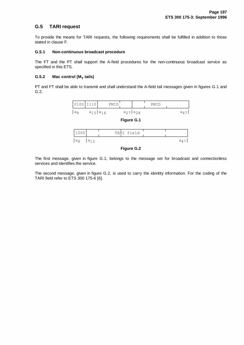
Page 197ETS 300 175-3: September 1996
G.5 TARI request
To provide the means for TARI requests, the following requirements shall be fulfilled in addition to thosestated in clause F.
G.5.1 Non-continuous broadcast procedure
The FT and the PT shall support the A-field procedures for the non-continuous broadcast service asspecified in this ETS.
G.5.2 Mac control (M T tails)
PT and FT shall be able to transmit and shall understand the A-field tail messages given in figures G.1 andG.2.
¸¶¶¶¶¾¶¶¶¶¾¶¶¶¶¶¶¶¶¾¶¶¶¶¾¶¶¶¶¾¶¶¶¶¶¶¶¶¶¶¶¶¶¶¶¶¶¹·����·����·����)0,'�����·�������30,'�����������·º¶¶¶¶¿¶¶¶¶¿¶¶¶¶¶¶¶¶¿¶¶¶¶¿¶¶¶¶¿¶¶¶¶¶¶¶¶¿¶¶¶¶¶¶¶¶»·D�����D��·D���������D��·D������������������D��·
Figure G.1
¸¶¶¶¶¾¶¶¶¶¾¶¶¶¶¶¶¶¶¾¶¶¶¶¶¶¶¶¾¶¶¶¶¶¶¶¶¾¶¶¶¶¶¶¶¶¹·����·�����������7$5,�ILHOG�������������������·º¶¶¶¶¿¶¶¶¶¿¶¶¶¶¶¶¶¶¿¶¶¶¶¶¶¶¶¿¶¶¶¶¶¶¶¶¿¶¶¶¶¶¶¶¶»·D���·D������������������������������������D��·
Figure G.2
The first message, given in figure G.1, belongs to the message set for broadcast and connectionlessservices and identifies the service.
The second message, given in figure G.2, is used to carry the identity information. For the coding of theTARI field refer to ETS 300 175-6 [6].

Page 198ETS 300 175-3: September 1996
Annex H (informative): Seamless handover operation
H.1 I-Channel data flow for I N_miminmum_delay service
When two bearers are maintained during bearer handover in a IN_minimum delay_service the datatransmitted in one frame is not the same for the two bearers using physical channels in different time slots.For transmission, the voice service description in the DLC (see ETS 300 175-4 [4]) (LU1) implies that theresponse on a MAC_CO_DTR-ind primitive is a MAC_CO_DATA-req primitive containing the latest octets.Therefore the data depends on the time instant when the MAC_CO_DTR-ind primitive was sent. Toachieve minimum delay the occurrence of this primitive should depend on the slot number used by aparticular physical channel. This implies that during a bearer handover two MAC_CO_DTR-ind primitivesare sent in one frame and two MAC_CO_DATA-req primitives are received by the MBC containingdifferent data for the old and the new bearer. For a handover in which no IN bits are to be lost or addeddue to the handover, synchronisation between MAC and DLC is necessary. It is recommended tosynchronise the MAC and DLC such that the relative offset in data octets for delivering IN_segments tobearers in different slot positions is given in tables H.1 and H.2.
Table H.1: Double slot operation
¸¶¶¶¶¶¶¶¶¶¶¶¶¶¶¶¶¶¶¶¾¶¶¶¶¶¶¶¶¶¶¶¶¶¶¶¶¶¶¶¶¾¶¶¶¶¶¶¶¶¶¶¶¶¶¶¶¶¶¶¶¶¶¹·��VORWV����RFWHW���·���VORWV����RFWHW���·����VORWV����RFWHW���·¼¶¶¶¶¶¶¶¶¶¶¶¶¶¶¶¶¶¶¶À¶¶¶¶¶¶¶¶¶¶¶¶¶¶¶¶¶¶¶¶À¶¶¶¶¶¶¶¶¶¶¶¶¶¶¶¶¶¶¶¶¶½·������������[������·�������������[������·�������������[�������··������������[������·�������������[������·�������������[�������·º¶¶¶¶¶¶¶¶¶¶¶¶¶¶¶¶¶¶¶¿¶¶¶¶¶¶¶¶¶¶¶¶¶¶¶¶¶¶¶¶¿¶¶¶¶¶¶¶¶¶¶¶¶¶¶¶¶¶¶¶¶¶»
NOTE 1: The slot numbers correspond to the slots where transmission on a double slot bearerstarts.
Table H.2: Full slot operation
¸¶¶¶¶¶¶¶¶¶¶¶¶¶¶¶¶¶¶¶¾¶¶¶¶¶¶¶¶¶¶¶¶¶¶¶¶¶¶¶¶¾¶¶¶¶¶¶¶¶¶¶¶¶¶¶¶¶¶¶¶¶¶¹·��VORWV����RFWHW���·���VORWV����RFWHW���·����VORWV����RFWHW���·¼¶¶¶¶¶¶¶¶¶¶¶¶¶¶¶¶¶¶¶À¶¶¶¶¶¶¶¶¶¶¶¶¶¶¶¶¶¶¶¶À¶¶¶¶¶¶¶¶¶¶¶¶¶¶¶¶¶¶¶¶¶½·������������[������·������������[�������·�������������[�������··������������[������·������������[�������·�������������[�������··������������[������·������������[�������·�������������[�������··������������[������·������������[�������·�������������[�������·º¶¶¶¶¶¶¶¶¶¶¶¶¶¶¶¶¶¶¶¿¶¶¶¶¶¶¶¶¶¶¶¶¶¶¶¶¶¶¶¶¿¶¶¶¶¶¶¶¶¶¶¶¶¶¶¶¶¶¶¶¶¶»
NOTE 2: For half slot operation: no recommendation.
Page 199ETS 300 175-3: September 1996
Annex J (informative): Bibliography
- CEPT Recommendation T/SGT SF2 (89) 6/0: "Draft Recommendation T/SF Services and Facilitiesof Digital European Cordless Telecommunications".
- ETR 043: "Radio Equipment and Systems (RES); Digital European Cordless Telecommunications(DECT); Common Interface; Services and facilities requirements specification".
- ETR 015: "Radio Equipment and Systems (RES) Digital European Cordless Telecommunications(DECT); Reference Document".
- ETR 056: "Radio Equipment and Systems (RES); Digital European Cordless Telecommunications(DECT); System description document".
- ETR 042: "Radio Equipment and Systems (RES); Digital European Cordless Telecommunications(DECT); A guide to the DECT features that influence the traffic capacity and the maintenance of highradio link transmission quality, including the results of simulations".
- W.W. Peterson and E.J. Weldon (1972, 2nd edit.): "Error Correcting Codes" (MIT Press,Cambridge, MA).

Page 200ETS 300 175-3: September 1996
History
Document history
October 1992 First Edition
July 1995 Public Enquiry PE 88: 1995-07-24 to 1995-11-17
June 1996 Vote V 106: 1996-06-24 to 1996-08-30
September 1996 Second Edition
ISBN 2-7437-0949-9 - Edition complète - Edition 2ISBN 2-7437-0952-9 - Partie 3 - Edition 2Dépôt légal : Septembre 1996