european ets 300 737 telecommunication · pdf fileets 300 737 (gsm 08.60 version 5 ... (e-trau...
TRANSCRIPT
EUROPEAN ETS 300 737
TELECOMMUNICATION February 1998
STANDARD Second Edition
Source: SMG Reference: RE/SMG-020860QR1
ICS: 33.020
Key words: Digital cellular telecommunications system, Global System for Mobile communications (GSM)
GLOBAL SYSTEM FOR MOBILE COMMUNICATIONS
R
Digital cellular telecommunications system (Phase 2+);
Inband control of remote transcoders and rate adaptors for
Enhanced Full Rate (EFR) and full rate traffic channels
(GSM 08.60 version 5.1.1)
ETSI
European Telecommunications Standards Institute
ETSI Secretariat
Postal address: F-06921 Sophia Antipolis CEDEX - FRANCEOffice address: 650 Route des Lucioles - Sophia Antipolis - Valbonne - FRANCEX.400: c=fr, a=atlas, p=etsi, s=secretariat - Internet: [email protected]
Tel.: +33 4 92 94 42 00 - Fax: +33 4 93 65 47 16
Copyright Notification: No part may be reproduced except as authorized by written permission. The copyright and theforegoing restriction extend to reproduction in all media.
© European Telecommunications Standards Institute 1998. All rights reserved.

Page 2ETS 300 737 (GSM 08.60 version 5.1.1): February 1998
Whilst every care has been taken in the preparation and publication of this document, errors in content,typographical or otherwise, may occur. If you have comments concerning its accuracy, please write to"ETSI Editing and Committee Support Dept." at the address shown on the title page.

Page 3ETS 300 737 (GSM 08.60 version 5.1.1): February 1998
Contents
Foreword ...........................................................................................................................................5
1 Scope.......................................................................................................................................71.1 Normative references...................................................................................................71.2 Abbreviations ..............................................................................................................8
2 General Approach .....................................................................................................................8
3 Frame Structure ......................................................................................................................113.1 Speech Frames.........................................................................................................113.2 O&M Frames ............................................................................................................123.3 Data Frames.............................................................................................................13
3.3.1 Data Frame (for Synchronisation) ............................................................133.3.2 Extended data frame (E-TRAU : data transport) .......................................14
3.4 Idle Speech Frames ..................................................................................................153.5 Coding......................................................................................................................15
3.5.1 Coding of Speech Frames.......................................................................163.5.2 Coding of O&M Frames ..........................................................................183.5.3 Coding of Data Frames...........................................................................183.5.4 Coding of Extended Data Frames ............................................................183.5.5 Coding of Idle Speech Frames.................................................................19
3.6. Order of Bit Transmission ..........................................................................................19
4 Procedures .............................................................................................................................194.1 Remote Control of Transcoders and Rate Adaptors .....................................................194.2 Resource Allocation...................................................................................................204.3 Resource Release.....................................................................................................204.4 In Call Modification ....................................................................................................204.5 Transfer of Idle Frames .............................................................................................21
4.5.1 In Full rate data case: .............................................................................214.5.2 In Full rate speech case: .........................................................................214.5.3 In Enhanced Full rate speech case:..........................................................21
4.6 Procedures for Speech Frames..................................................................................214.6.1 Time Alignment of Speech Frames...........................................................21
4.6.1.1 Initial Time Alignment State..............................................214.6.1.2 The Static Time Alignment State ......................................224.6.1.3 Initiation at Resource Allocation........................................244.6.1.4 Time Alignment During Handover......................................24
4.6.1.4.1 BSS External Handover.......................244.6.1.4.2 BSS Internal Handover........................24
4.6.2 Procedures for Discontinuous Transmission (DTX) ....................................244.6.2.1 DTX procedures in the uplink direction ..............................244.6.2.2 DTX procedures in the downlink direction..........................24
4.7 Procedures for Data Frames......................................................................................254.7.1 9.6 and 4.8 kbit/s channel coding................................................................................25
4.7.1.1 The RAA Function...................................................................................254.7.1.2 The RA1/RA1' Function ...........................................................................264.7.1.3 The RA2 Function ...................................................................................264.7.1.4 Procedures for 8 kbit/s intermediate rate adaption rate .............................264.7.1.5 Procedures for 16 kbit/s intermediate rate adaption rate............................264.7.1.6 Support of Non-Transparent Bearer Applications.......................................27
4.7.2 14.5 kbit/s channel coding ..........................................................................................274.7.2.1 The RAA’ Function ..................................................................................274.7.2.2 The RA1’/RAA' Function ..........................................................................27

Page 4ETS 300 737 (GSM 08.60 version 5.1.1): February 1998
4.7.2.3 The RA2 Function ...................................................................................274.8 Frame Synchronization...............................................................................................27
4.8.1 Search for Frame Synchronization............................................................274.8.2 Frame Synchronization After Performing Downlink Timing Adjustments........274.8.3 Frame Synchronization Monitoring and Recovery.......................................28
4.9 Correction/detection of bit errors on the terrestrial circuits ............................................294.9.1 Error Detection on the Control Bits...........................................................29
4.9.1.1 General Procedure..........................................................294.9.1.2 Speech Frames ..............................................................29
4.9.2 Handling of frames received with errors....................................................294.9.2.1 In case of Full Rate: ........................................................294.9.2.2 In case of Enhanced Full rate:..........................................30
4.10 Procedures for Operation & Maintenance ....................................................................304.10.1 Transfer of O&M Information Between the TRAU and the BSC...................304.10.2 Procedures in the TRAU..........................................................................304.10.3 Procedures in the BSC............................................................................30
4.10.3.1 Use of O&M Frames .......................................................314.10.4 Procedures in the BTS ............................................................................31
History..............................................................................................................................................32
Page 5ETS 300 737 (GSM 08.60 version 5.1.1): February 1998
Foreword
This European Telecommunication Standard (ETS) has been produced by the Special Mobile Group(SMG) of the European Telecommunications Standards Institute (ETSI).
This ETS specifies the inband control of remote transcoders and rate adaptors for full rate speech,Enhanced Full rate speech and full rate data within the Digital cellular telecommunications system(Phase 2+).
The specification from which this ETS has been derived was originally based on CEPT documentation,hence the presentation of this ETS may not be entirely in accordance with the ETSI/PNE Rules.
Transposition dates
Date of adoption of this ETS: 23 January 1998
Date of latest announcement of this ETS (doa): 31 May 1998
Date of latest publication of new National Standardor endorsement of this ETS (dop/e): 30 November 1998
Date of withdrawal of any conflicting National Standard (dow): 30 November 1998

Page 6ETS 300 737 (GSM 08.60 version 5.1.1): February 1998
Blank page
Page 7ETS 300 737 (GSM 08.60 version 5.1.1): February 1998
1 Scope
When 64 kbit/s traffic channels are used on the Abis interface, the speech shall be coded according toCCITT Recommendation G.711 and the data rate adaptation shall be as specified in GSM 04.21 and GSM08.20.
In the case where 16 kbit/s traffic channels are used for full rate speech or enhanced full rate speech orfull rate data service, then this specification shall apply for frame structure and for control of remotetranscoders and additional rate adaptors.
The use and general aspects of the Abis interface are given in GSM 08.51.
NOTE: This specification should be considered together with the GSM 06 series ofspecifications, GSM 04.21 (Rate Adaptation on the MS-BSS Interface) and GSM08.20 (Rate Adaptation on the BS/MSC Interface).
1.1 Normative references
This ETS incorporates by dated and undated reference, provisions from other publications. Thesenormative references are cited at the appropriate places in the text and the publications are listedhereafter. For dated references, subsequent amendments to or revisions of any of these publications applyto this ETS only when incorporated in it by amendment or revision. For undated references, the latestedition of the publication referred to applies.
[1] GSM 01.04 (ETR 350): "Digital cellular telecommunications system (Phase 2+);Abbreviations and acronyms".
[2] GSM 04.06 (ETS 300 938): "Digital cellular telecommunications system; MobileStation - Base Station System (MS - BSS) interface; Data Link (DL) layerspecification".
[3] GSM 04.21 (ETS 300 945): "Digital cellular telecommunications system; Rateadaption on the Mobile Station - Base Station System (MS - BSS) interface".
[4] GSM 06.01 (ETS 300 960): "Digital cellular telecommunications system; Full ratespeech; Processing functions".
[5] GSM 06.10 (ETS 300 961): "Digital cellular telecommunications system; Full ratespeech; Transcoding".
[6] GSM 06.11 (ETS 300 962): "Digital cellular telecommunications system; Full ratespeech; Substitution and muting of lost frames for full rate speech channels".
[7] GSM 06.12 (ETS 300 963): "Digital cellular telecommunications system; Full ratespeech; Comfort noise aspect for full rate speech traffic channels".
[8] GSM 06.31 (ETS 300 964): "Digital cellular telecommunications system; Full ratespeech; Discontinuous Transmission (DTX) for full rate speech traffic channels".
[9] GSM 06.32 (ETS 300 965): "Digital cellular telecommunications system; VoiceActivity Detector (VAD)".
[10] GSM 08.20: "Digital cellular telecommunications system; Rate adaption on theBase Station System - Mobile-services Switching Centre (BSS - MSC)interface".
[11] GSM 08.51: "Digital cellular telecommunications system; Base Station Controller- Base Transceiver Station (BSC - BTS) interface; General aspects".

Page 8ETS 300 737 (GSM 08.60 version 5.1.1): February 1998
[12] GSM 08.54: "Digital cellular telecommunications system (Phase 2+); BaseStation Controller - Base Transceiver Station (BSC - BTS) interface; Layer 1structure of physical circuits".
[13] GSM 08.58: "Digital cellular telecommunications system (Phase 2+); BaseStation Controller - Base Transceiver Station (BSC - BTS) interface; Layer 3specification".
[14] GSM 12.21 (ETS 300 623): "Digital cellular telecommunications system(Phase 2); Network Management (NM) procedures and message on the A-bisinterface".
[15] CCITT Recommendation G.711: "Pulse code modulation (PCM) of voicefrequencies".
[16] CCITT Recommendation I.460: "Multiplexing, rate adaption and support ofexisting interfaces".
[17] CCITT Recommendation V.110: "Support of data terminal equipments (DTEs)with V-Series interfaces by an integrated services digital network".
[18] GSM 06.51 (ETS 300 723): "Digital cellular telecommunications system;Enhanced Full rate speech processing functions".
[19] GSM 06.60 (ETS 300 726): "Digital cellular telecommunications system;Enhanced Full rate speech transcoding".
[20] GSM 06.61 (ETS 300 727): "Digital cellular telecommunications system;Substitution and muting of lost frames for Enhanced Full rate speech channels".
[21] GSM 06.62 (ETS 300 728): "Digital cellular telecommunications system; Comfortnoise aspect for Enhanced Full rate speech traffic channels".
[22] GSM 06.81 (ETS 300 729): "Digital cellular telecommunications system;Discontinuous Transmission (DTX) for Enhanced Full rate speech trafficchannel".
[23] GSM 06.82 (ETS 300 730): "Digital cellular telecommunications system; VoiceActivity Detection (VAD)".
1.2 Abbreviations
Abbreviations used in this specification are listed in GSM 01.04.
2 General Approach
When the transcoders/rate adaptors are positioned remote to the BTS, the information between theChannel Codec Unit (CCU) and the remote Transcoder/Rate Adaptor Unit (TRAU) is transferred in frameswith a fixed length of 320 bits (20 mS). In this specification, these frames are denoted "TRAU frames".Within these frames, both the speech/data and the TRAU associated control signals are transferred.
The Abis interface should be the same if the transcoder is positioned 1) at the MSC site of the BSS or if itis positioned 2) at the BSC site of the BSS. In case 1), the BSC should be considered as transparent for16 kbit/s channels.
In case of 4,8 and 9,6 kbit/s channel coding when data is adapted to the 320 bit frames, a conversionfunction is required in addition to the conversion/rate adaption specified in GSM 08.20. This functionconstitutes the RAA. In case of 14,5 kbit/s channel coding, no RAA rate adaption is required becauseV.110 framing is not used.
Page 9ETS 300 737 (GSM 08.60 version 5.1.1): February 1998
The TRAU is considered a part of the BSC, and the signalling between the BSC and the TRAU (e.g.detection of call release, handover and transfer of O&M information) may be performed by using BSCinternal signals. The signalling between the CCU and the TRAU, using TRAU frames as specified in thisspecification, is mandatory when the Abis interface is applied.
NOTE: If standard 64 kbit/s switching is used in the BSC, multiplexing according to CCITTRecommendation I.460 should apply at both sides of the switch.
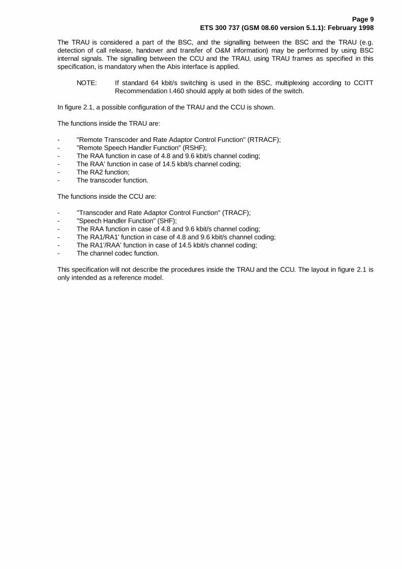
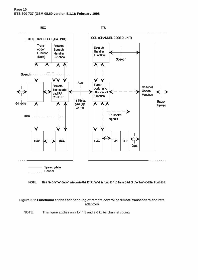
In figure 2.1, a possible configuration of the TRAU and the CCU is shown.
The functions inside the TRAU are:
- "Remote Transcoder and Rate Adaptor Control Function" (RTRACF);- "Remote Speech Handler Function" (RSHF);- The RAA function in case of 4.8 and 9.6 kbit/s channel coding;- The RAA’ function in case of 14.5 kbit/s channel coding;- The RA2 function;- The transcoder function.
The functions inside the CCU are:
- "Transcoder and Rate Adaptor Control Function" (TRACF);- "Speech Handler Function" (SHF);- The RAA function in case of 4.8 and 9.6 kbit/s channel coding;- The RA1/RA1' function in case of 4.8 and 9.6 kbit/s channel coding;- The RA1’/RAA’ function in case of 14.5 kbit/s channel coding;- The channel codec function.
This specification will not describe the procedures inside the TRAU and the CCU. The layout in figure 2.1 isonly intended as a reference model.
Page 10ETS 300 737 (GSM 08.60 version 5.1.1): February 1998
Figure 2.1: Functional entities for handling of remote control of remote transcoders and rateadaptors
NOTE: This figure applies only for 4,8 and 9,6 kbit/s channel coding

Page 11ETS 300 737 (GSM 08.60 version 5.1.1): February 1998
3 Frame Structure
3.1 Speech Frames
Bit number
Octet no. 1 2 3 4 5 6 7 80 0 0 0 0 0 0 0 01 0 0 0 0 0 0 0 02 1 C1 C2 C3 C4 C5 C6 C73 C8 C9 C10 C11 C12 C13 C14 C154 1 D1 D2 D3 D4 D5 D6 D75 D8 D9 D10 D11 D12 D13 D14 D156 1 D16 D17 D18 D19 D20 D21 D227 D23 D24 D25 D26 D27 D28 D29 D308 1 D31 D32 D33 D34 D35 D36 D379 D38 D39 D40 D41 D42 D43 D44 D45
10 1 D46 D47 D48 D49 D50 D51 D5211 D53 D54 D55 D56 D57 D58 D59 D6012 1 D61 D62 D63 D64 D65 D66 D6713 D68 D69 D70 D71 D72 D73 D74 D7514 1 D76 D77 D78 D79 D80 D81 D8215 D83 D84 D85 D86 D87 D88 D89 D9016 1 D91 D92 D93 D94 D95 D96 D9717 D98 D99 D100 D101 D102 D103 D104 D10518 1 D106 D107 D108 D109 D110 D111 D11219 D113 D114 D115 D116 D117 D118 D119 D12020 1 D121 D122 D123 D124 D125 D126 D12721 D128 D129 D130 D131 D132 D133 D134 D13522 1 D136 D137 D138 D139 D140 D141 D14223 D143 D144 D145 D146 D147 D148 D149 D15024 1 D151 D152 D153 D154 D155 D156 D15725 D158 D159 D160 D161 D162 D163 D164 D16526 1 D166 D167 D168 D169 D170 D171 D17227 D173 D174 D175 D176 D177 D178 D179 D18028 1 D181 D182 D183 D184 D185 D186 D18729 D188 D189 D190 D191 D192 D193 D194 D19530 1 D196 D197 D198 D199 D200 D201 D20231 D203 D204 D205 D206 D207 D208 D209 D21032 1 D211 D212 D213 D214 D215 D216 D21733 D218 D219 D220 D221 D222 D223 D224 D22534 1 D226 D227 D228 D229 D230 D231 D23235 D233 D234 D235 D236 D237 D238 D239 D24036 1 D241 D242 D243 D244 D245 D246 D24737 D248 D249 D250 D251 D252 D253 D254 D25538 1 D256 D257 D258 D259 D260 C16 C1739 C18 C19 C20 C21 T1 T2 T3 T4
Page 12ETS 300 737 (GSM 08.60 version 5.1.1): February 1998
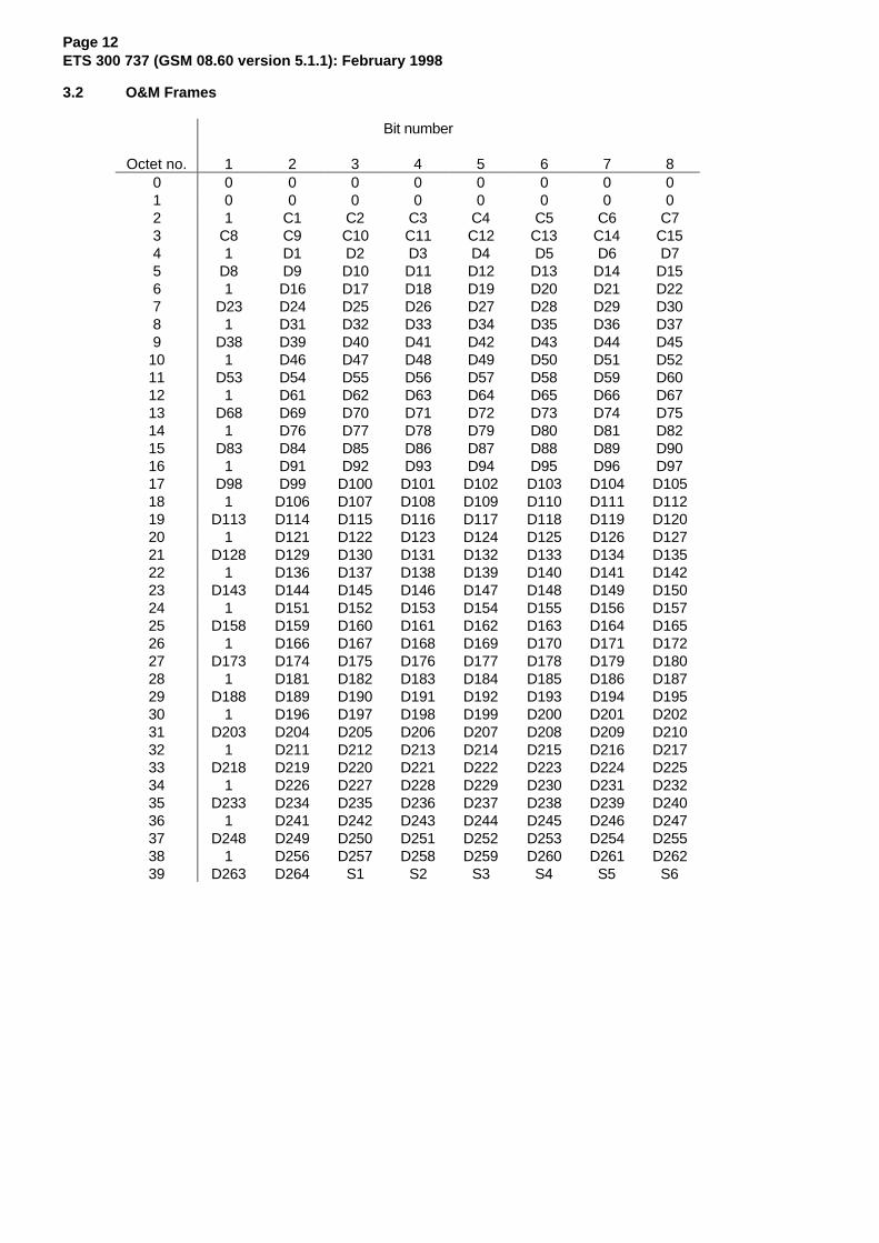
3.2 O&M Frames
Bit number
Octet no. 1 2 3 4 5 6 7 80 0 0 0 0 0 0 0 01 0 0 0 0 0 0 0 02 1 C1 C2 C3 C4 C5 C6 C73 C8 C9 C10 C11 C12 C13 C14 C154 1 D1 D2 D3 D4 D5 D6 D75 D8 D9 D10 D11 D12 D13 D14 D156 1 D16 D17 D18 D19 D20 D21 D227 D23 D24 D25 D26 D27 D28 D29 D308 1 D31 D32 D33 D34 D35 D36 D379 D38 D39 D40 D41 D42 D43 D44 D45
10 1 D46 D47 D48 D49 D50 D51 D5211 D53 D54 D55 D56 D57 D58 D59 D6012 1 D61 D62 D63 D64 D65 D66 D6713 D68 D69 D70 D71 D72 D73 D74 D7514 1 D76 D77 D78 D79 D80 D81 D8215 D83 D84 D85 D86 D87 D88 D89 D9016 1 D91 D92 D93 D94 D95 D96 D9717 D98 D99 D100 D101 D102 D103 D104 D10518 1 D106 D107 D108 D109 D110 D111 D11219 D113 D114 D115 D116 D117 D118 D119 D12020 1 D121 D122 D123 D124 D125 D126 D12721 D128 D129 D130 D131 D132 D133 D134 D13522 1 D136 D137 D138 D139 D140 D141 D14223 D143 D144 D145 D146 D147 D148 D149 D15024 1 D151 D152 D153 D154 D155 D156 D15725 D158 D159 D160 D161 D162 D163 D164 D16526 1 D166 D167 D168 D169 D170 D171 D17227 D173 D174 D175 D176 D177 D178 D179 D18028 1 D181 D182 D183 D184 D185 D186 D18729 D188 D189 D190 D191 D192 D193 D194 D19530 1 D196 D197 D198 D199 D200 D201 D20231 D203 D204 D205 D206 D207 D208 D209 D21032 1 D211 D212 D213 D214 D215 D216 D21733 D218 D219 D220 D221 D222 D223 D224 D22534 1 D226 D227 D228 D229 D230 D231 D23235 D233 D234 D235 D236 D237 D238 D239 D24036 1 D241 D242 D243 D244 D245 D246 D24737 D248 D249 D250 D251 D252 D253 D254 D25538 1 D256 D257 D258 D259 D260 D261 D26239 D263 D264 S1 S2 S3 S4 S5 S6
Page 13ETS 300 737 (GSM 08.60 version 5.1.1): February 1998
3.3 Data Frames
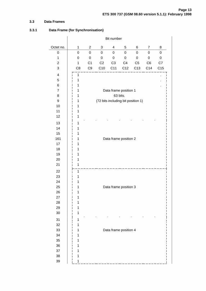
3.3.1 Data Frame (for Synchronisation)
Bit number
Octet no. 1 2 3 4 5 6 7 8
0 0 0 0 0 0 0 0 0
1 0 0 0 0 0 0 0 0
2 1 C1 C2 C3 C4 C5 C6 C7
3 C8 C9 C10 C11 C12 C13 C14 C15
4 1 .
5 1 .
6 1 .
7 1 Data frame position 1
8 1 63 bits.
9 1 (72 bits including bit position 1)
10 1
11 1
12 1
13 1
14 1
15 1
161 1 Data frame position 2
17 1
18 1
19 1
20 1
21 1
22 1
23 1
24 1
25 1 Data frame position 3
26 1
27 1
28 1
29 1
30 1
31 1
32 1
33 1 Data frame position 4
34 1
35 1
36 1
37 1
38 1
39 1

Page 14ETS 300 737 (GSM 08.60 version 5.1.1): February 1998
3.3.2 Extended data frame (E-TRAU : data transport)
Bit number
Octet no. 1 2 3 4 5 6 7 8
0 0 0 0 0 0 0 0 0
1 0 0 0 0 0 0 0 0
2 1 C1 C2 C3 C4 C5 C6 C7
3 C8 C9 C10 C11 C12 C13 M1 M2
4 D1 D2 ...
5
6
7 Data block of 288 data bits and M1, M2.
8
9
10
11
12
13
14
15
16
17
18
19
20
21
22
23
24
25
26
27
28
29
30
31
32
33
34
35
36
37
38
39 ... D287 D288

Page 15ETS 300 737 (GSM 08.60 version 5.1.1): February 1998
3.4 Idle Speech Frames
Bit number
Octet no. 1 2 3 4 5 6 7 80 0 0 0 0 0 0 0 01 0 0 0 0 0 0 0 02 1 C1 C2 C3 C4 C5 C6 C73 C8 C9 C10 C11 C12 C13 C14 C154 1 1 1 1 1 1 1 15 1 1 1 1 1 1 1 16 1 1 1 1 1 1 1 17 1 1 1 1 1 1 1 18 1 1 1 1 1 1 1 19 1 1 1 1 1 1 1 1
10 1 1 1 1 1 1 1 111 1 1 1 1 1 1 1 112 1 1 1 1 1 1 1 113 1 1 1 1 1 1 1 114 1 1 1 1 1 1 1 115 1 1 1 1 1 1 1 116 1 1 1 1 1 1 1 117 1 1 1 1 1 1 1 118 1 1 1 1 1 1 1 119 1 1 1 1 1 1 1 120 1 1 1 1 1 1 1 121 1 1 1 1 1 1 1 122 1 1 1 1 1 1 1 123 1 1 1 1 1 1 1 124 1 1 1 1 1 1 1 125 1 1 1 1 1 1 1 126 1 1 1 1 1 1 1 127 1 1 1 1 1 1 1 128 1 1 1 1 1 1 1 129 1 1 1 1 1 1 1 130 1 1 1 1 1 1 1 131 1 1 1 1 1 1 1 132 1 1 1 1 1 1 1 133 1 1 1 1 1 1 1 134 1 1 1 1 1 1 1 135 1 1 1 1 1 1 1 136 1 1 1 1 1 1 1 137 1 1 1 1 1 1 1 138 1 1 1 1 1 1 C16 C1739 C18 C19 C20 C21 T1 T2 T3 T4
3.5 Coding
In the following sections, the coding of the frames is described. Any spare or not used control bits shouldbe coded binary "1".
For all frame types the octet 0, 1 and the first bit of octets 2, 4, 6, 8, ... 38 are used as frame sync.

Page 16ETS 300 737 (GSM 08.60 version 5.1.1): February 1998
3.5.1 Coding of Speech Frames
Control bits (C-bits):
Description Uplink Downlink
C1C2C3C4 C5 C1C2C3C4 C5Frame type FR Speech: 0 0 0 1 0. Speech: 1 1 1 0 0(Bits C1 - C5). EFR Speech: 1 1 0 1 0 Speech: 1 1 0 1 0
Time Binary number indicating the Binary number indicatingAlignment required timing adjustment to the timing adjustment made.(Bits C6 - C11) be made in steps of 250/500 µs.
The following values apply for the codingC6C7 . . . C11 0 0 0 0 0 0 No change in frame timing 0 0 0 0 0 1 Delay frame 1 x 500 µs 0 0 0 0 1 0 Delay frame 2 x 500 µs . . . .... . . . .... 1 0 0 1 1 1 Delay frame 39 x 500 µs 1 0 1 0 0 0 Not used . . . .... 1 1 1 1 0 1 Not used 1 1 1 1 1 0 Delay frame 1 x 250 µs 1 1 1 1 1 1 Advance frame 250 µs
Frame indicators. The definition C12: BFI C12 - C15: Spareand coding of these indicators 0 : BFI = 0are given in GSM 06.31. 1 : BFI = 1 IF FR. Speech
C13 C14: SID ELSEBits C12 - C16 0 0 :SID = 0 C12: UFE
0 1 :SID = 1 0 :UFE=0 bad uplink frame 1 0 :SID = 2 1 : UFE=1 good up-link frame
Downlink Uplink Frame Error C15: TAF(UFE) C12 0 : TAF = 0(see subclause 4.8.3) 1 : TAF = 1 C13 - C15: spare
C16: Spare C16: SP 0 : SP = 0 1 : SP = 1
DTX indicator C17: DTXd C17: Spare0 : DTX not applied1 : DTX applied
Bits C18 - C21 Spare Spare
Page 17ETS 300 737 (GSM 08.60 version 5.1.1): February 1998
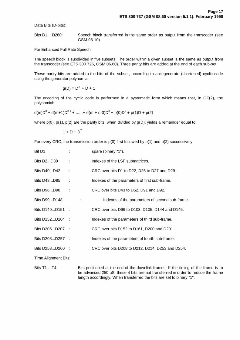
Data Bits (D-bits):
Bits D1 .. D260: Speech block transferred in the same order as output from the transcoder (seeGSM 06.10).
For Enhanced Full Rate Speech:
The speech block is subdivided in five subsets. The order within a given subset is the same as output fromthe transcoder (see ETS 300 726, GSM 06.60). Three parity bits are added at the end of each sub-set.
These parity bits are added to the bits of the subset, according to a degenerate (shortened) cyclic codeusing the generator polynomial:
g(D) = D3 + D + 1
The encoding of the cyclic code is performed in a systematic form which means that, in GF(2), thepolynomial:
d(m)Dn + d(m+1)Dn-1 + ......+ d(m + n-3)D3 + p(0)D2 + p(1)D + p(2)
where p(0), p(1), p(2) are the parity bits, when divided by g(D), yields a remainder equal to:
1 + D + D2
For every CRC, the transmission order is p(0) first followed by p(1) and p(2) successively.
Bit D1 : spare (binary "1").
Bits D2...D39 : Indexes of the LSF submatrices.
Bits D40...D42 : CRC over bits D1 to D22, D25 to D27 and D29.
Bits D43...D95 : Indexes of the parameters of first sub-frame.
Bits D96...D98 : CRC over bits D43 to D52, D91 and D92.
Bits D99...D148 : Indexes of the parameters of second sub-frame.
Bits D149...D151 : CRC over bits D99 to D103, D105, D144 and D145.
Bits D152...D204 : Indexes of the parameters of third sub-frame.
Bits D205...D207 : CRC over bits D152 to D161, D200 and D201.
Bits D208...D257 : Indexes of the parameters of fourth sub-frame.
Bits D258...D260 : CRC over bits D208 to D212, D214, D253 and D254.
Time Alignment Bits:
Bits T1 .. T4: Bits positioned at the end of the downlink frames. If the timing of the frame is tobe advanced 250 µS, these 4 bits are not transferred in order to reduce the framelength accordingly. When transferred the bits are set to binary "1".

Page 18ETS 300 737 (GSM 08.60 version 5.1.1): February 1998
3.5.2 Coding of O&M Frames
Control bits (C-bits):
Description Uplink DownlinkC1C2C3C4 C5 C1C2C3C4 C5
Frame type 0 0 1 0 1 : O&M 1 1 0 1 1 : O&M Bits C1 - C5 Bits C6 - C15 Spare Spare
Data Bits (D-bits):
Bits D1 .. D264: Bits used for transfer of O&M information. The coding and use of these bits areleft to the manufacturer of the BSC/TRAU.
Spare Bits:
Bits S1 .. S6: Spare
3.5.3 Coding of Data Frames
Control bits (C-bits):
Description Uplink DownlinkFrame type. C1C2C3C4 C5 C1C2C3C4 C5Bits C1 - C5 0 1 0 0 0 : Data 1 0 1 1 0 : Data
except 14.5 except 14.5
1 0 1 0 0 : Data14.51) 1 0 1 0 0 : Data 14.51)
Intermediate RA bit 0: 8 kbit/s 0: 8 kbit/srate. 1: 16 kbit/s 1: 16 kbit/sBit C6for data servicesexcept 14.5Spare Spare Sparefor Data 14.5Bits C7 - C15 Spare Spare
NOTE 1: The Data frame is in case of data 14.5 kbit/s used only for synchronization purposes.The data bits are in this case set according to subclause 4.5.1.
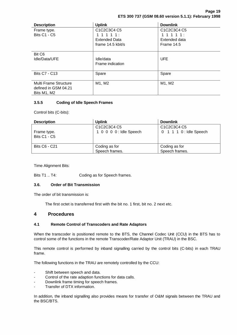
3.5.4 Coding of Extended Data Frames
Control bits (C-bits):
Page 19ETS 300 737 (GSM 08.60 version 5.1.1): February 1998
Description Uplink DownlinkFrame type. C1C2C3C4 C5 C1C2C3C4 C5Bits C1 - C5 1 1 1 1 1 : 1 1 1 1 1 :
Extended Data Extended dataframe 14.5 kbit/s Frame 14.5
Bit C6Idle/Data/UFE Idle/data UFE
Frame indication
Bits C7 - C13 Spare Spare
Multi Frame Structure M1, M2 M1, M2defined in GSM 04.21Bits M1, M2
3.5.5 Coding of Idle Speech Frames
Control bits (C-bits):
Description Uplink DownlinkC1C2C3C4 C5 C1C2C3C4 C5
Frame type. 1 0 0 0 0 : Idle Speech 0 1 1 1 0 : Idle SpeechBits C1 - C5
Bits C6 - C21 Coding as for Coding as forSpeech frames. Speech frames.
Time Alignment Bits:
Bits T1 .. T4: Coding as for Speech frames.
3.6. Order of Bit Transmission
The order of bit transmission is:
The first octet is transferred first with the bit no. 1 first, bit no. 2 next etc.
4 Procedures
4.1 Remote Control of Transcoders and Rate Adaptors
When the transcoder is positioned remote to the BTS, the Channel Codec Unit (CCU) in the BTS has tocontrol some of the functions in the remote Transcoder/Rate Adaptor Unit (TRAU) in the BSC.
This remote control is performed by inband signalling carried by the control bits (C-bits) in each TRAUframe.
The following functions in the TRAU are remotely controlled by the CCU:
- Shift between speech and data.- Control of the rate adaption functions for data calls.- Downlink frame timing for speech frames.- Transfer of DTX information.
In addition, the inband signalling also provides means for transfer of O&M signals between the TRAU andthe BSC/BTS.
Page 20ETS 300 737 (GSM 08.60 version 5.1.1): February 1998
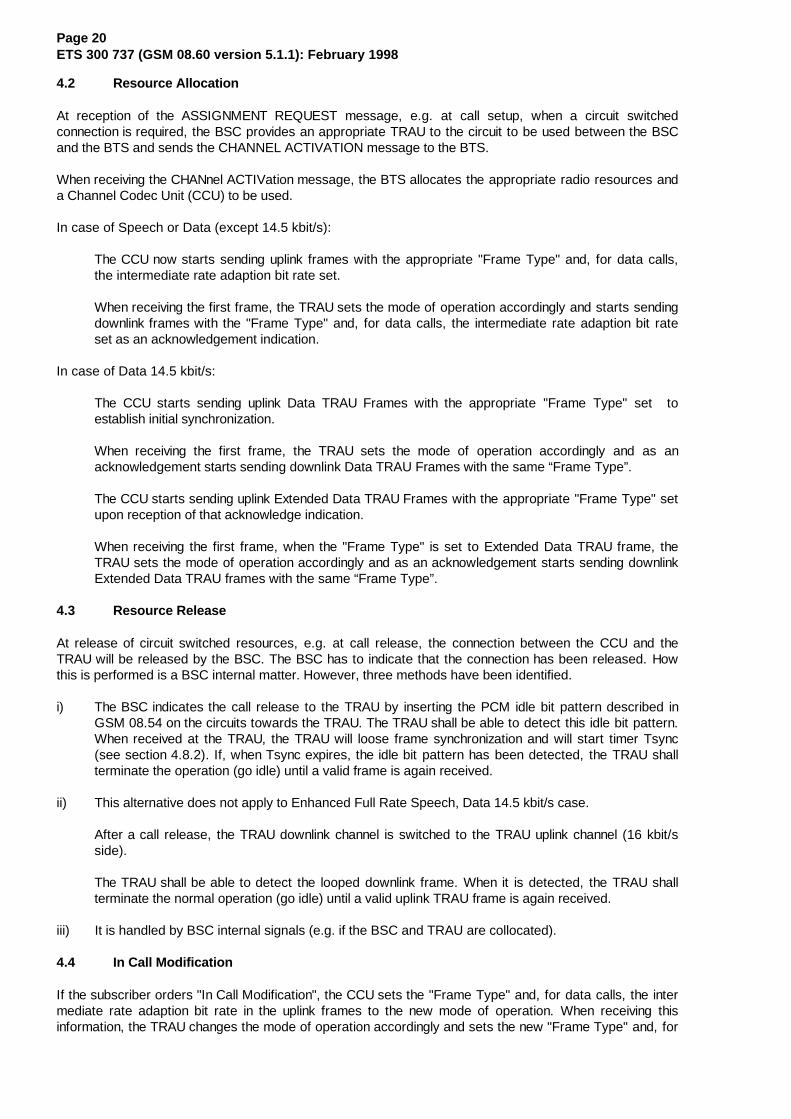
4.2 Resource Allocation
At reception of the ASSIGNMENT REQUEST message, e.g. at call setup, when a circuit switchedconnection is required, the BSC provides an appropriate TRAU to the circuit to be used between the BSCand the BTS and sends the CHANNEL ACTIVATION message to the BTS.
When receiving the CHANnel ACTIVation message, the BTS allocates the appropriate radio resources anda Channel Codec Unit (CCU) to be used.
In case of Speech or Data (except 14.5 kbit/s):
The CCU now starts sending uplink frames with the appropriate "Frame Type" and, for data calls,the intermediate rate adaption bit rate set.
When receiving the first frame, the TRAU sets the mode of operation accordingly and starts sendingdownlink frames with the "Frame Type" and, for data calls, the intermediate rate adaption bit rateset as an acknowledgement indication.
In case of Data 14.5 kbit/s:
The CCU starts sending uplink Data TRAU Frames with the appropriate "Frame Type" set toestablish initial synchronization.
When receiving the first frame, the TRAU sets the mode of operation accordingly and as anacknowledgement starts sending downlink Data TRAU Frames with the same “Frame Type”.
The CCU starts sending uplink Extended Data TRAU Frames with the appropriate "Frame Type" setupon reception of that acknowledge indication.
When receiving the first frame, when the "Frame Type" is set to Extended Data TRAU frame, theTRAU sets the mode of operation accordingly and as an acknowledgement starts sending downlinkExtended Data TRAU frames with the same “Frame Type”.
4.3 Resource Release
At release of circuit switched resources, e.g. at call release, the connection between the CCU and theTRAU will be released by the BSC. The BSC has to indicate that the connection has been released. Howthis is performed is a BSC internal matter. However, three methods have been identified.
i) The BSC indicates the call release to the TRAU by inserting the PCM idle bit pattern described inGSM 08.54 on the circuits towards the TRAU. The TRAU shall be able to detect this idle bit pattern.When received at the TRAU, the TRAU will loose frame synchronization and will start timer Tsync(see section 4.8.2). If, when Tsync expires, the idle bit pattern has been detected, the TRAU shallterminate the operation (go idle) until a valid frame is again received.
ii) This alternative does not apply to Enhanced Full Rate Speech, Data 14.5 kbit/s case.
After a call release, the TRAU downlink channel is switched to the TRAU uplink channel (16 kbit/sside).
The TRAU shall be able to detect the looped downlink frame. When it is detected, the TRAU shallterminate the normal operation (go idle) until a valid uplink TRAU frame is again received.
iii) It is handled by BSC internal signals (e.g. if the BSC and TRAU are collocated).
4.4 In Call Modification
If the subscriber orders "In Call Modification", the CCU sets the "Frame Type" and, for data calls, the intermediate rate adaption bit rate in the uplink frames to the new mode of operation. When receiving thisinformation, the TRAU changes the mode of operation accordingly and sets the new "Frame Type" and, for
Page 21ETS 300 737 (GSM 08.60 version 5.1.1): February 1998
data calls, the intermediate rate adaption bit rate in the downlink frames. The same procedure applies formode change between Data 14,5 kbit/s.
In case of mode change to data 14,5 kbit/s from Speech or Data (other than 14.5 kbit/s) the sameprocedure as for “Resource Allocation” is performed.
4.5 Transfer of Idle Frames
Between the TRAU and the CCU a TRAU frame shall be transferred every 20 mS.
4.5.1 In Full rate data case:
If no data is received from the MS (uplink direction) or no data is received from the MSC side of theinterface (downlink direction), idle data frames shall be transferred instead of data frames. Idle dataframes are data frames with all data bit positions set to binary "1". In addition, for 14,5 kbit/s channelcoding; the C6 bit shall be set to ‘1’ in the uplink extended data frame.
4.5.2 In Full rate speech case:
If no speech is received from the MS (uplink direction), the CCU shall send TRAU speech frames with BFIflag set to 1 (bad frame) or idle speech frames.If no speech is received from the MSC side of the interface(downlink direction), idle speech frames shall be transferred instead of speech frames.
4.5.3 In Enhanced Full rate speech case:
If no speech is received from the MS (uplink direction), the CCU shall send TRAU speech frames with BFIflag set to 1 (bad frame). If no speech is received from the MSC side of the interface (downlink direction),idle speech frames shall be transferred instead of speech frames.
4.6 Procedures for Speech Frames
4.6.1 Time Alignment of Speech Frames
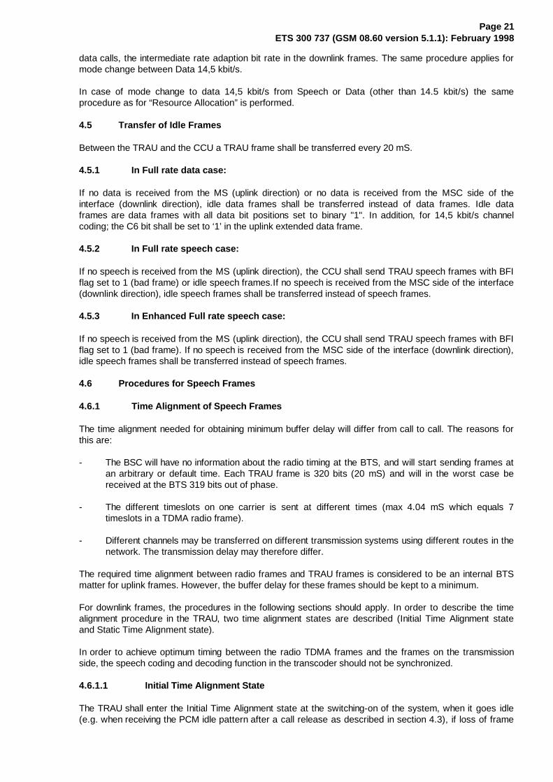
The time alignment needed for obtaining minimum buffer delay will differ from call to call. The reasons forthis are:
- The BSC will have no information about the radio timing at the BTS, and will start sending frames atan arbitrary or default time. Each TRAU frame is 320 bits (20 mS) and will in the worst case bereceived at the BTS 319 bits out of phase.
- The different timeslots on one carrier is sent at different times (max 4.04 mS which equals 7timeslots in a TDMA radio frame).
- Different channels may be transferred on different transmission systems using different routes in thenetwork. The transmission delay may therefore differ.
The required time alignment between radio frames and TRAU frames is considered to be an internal BTSmatter for uplink frames. However, the buffer delay for these frames should be kept to a minimum.
For downlink frames, the procedures in the following sections should apply. In order to describe the timealignment procedure in the TRAU, two time alignment states are described (Initial Time Alignment stateand Static Time Alignment state).
In order to achieve optimum timing between the radio TDMA frames and the frames on the transmissionside, the speech coding and decoding function in the transcoder should not be synchronized.
4.6.1.1 Initial Time Alignment State
The TRAU shall enter the Initial Time Alignment state at the switching-on of the system, when it goes idle(e.g. when receiving the PCM idle pattern after a call release as described in section 4.3), if loss of frame

Page 22ETS 300 737 (GSM 08.60 version 5.1.1): February 1998
synchronization is detected, in call modification from data to speech is performed or if BSS internalhandover is detected.
In the initial state, the frames shall only be delayed (or no change)(see note). The transcoder is able toadjust the time for transmitting the speech frames in steps of 125 µS (one speech sample). The CCUcalculates the required timing adjustment and returns a frame including the number of 250/500 µS steps bywhich the frames in the downlink direction have to be delayed (binary number in the "Time Alignment" field).
When receiving this information, the TRAU processes this data and sets the "Time Alignment" field in thenext downlink frame as ordered and then delays the subsequent frame accordingly.
NOTE: If the TRAU, in this state, receives an order to advance the next frame 250 µS, thisorder shall be interpreted as "Delay frame 39*500 µS".
When a frame is delayed due to timing adjustments, the TRAU shall fill in the gap between the frames withthe appropriate number of binary "1".
After having adjusted the timing, the TRAU shall receive at least three new frames before a newadjustment is made. This in order to avoid oscillation in the regulation.
The TRAU shall change from the Initial Time Alignment state to the Static Time Alignment state when it hasperformed two subsequent timing adjustments which are less than 500 µS (including no change).
The procedure is illustrated in figure 4.1.
4.6.1.2 The Static Time Alignment State
In the Static Time Alignment state, the TRAU performs timing adjustments in single steps of 250 µS. Thetiming may either be delayed (time alignment code 111110, advanced (time alignment code 111111) or notchanged (time alignment code 000000).
When receiving an order for adjusting the timing, the transcoder skips or repeats two speech samples inorder to achieve the correct timing.
If the timing is to be advanced 250 µS, the TRAU sets the "Time Alignment" field in the next downlink frameas ordered and then the 4 last bits of the frame are not transferred (the T-bits).
If the timing is to be delayed, the TRAU sets the "Time Alignment" field in the next downlink frame asordered and then delays the subsequent frame by adding four binary "1" between the frames.
After having adjusted the timing, the TRAU shall receive at least three new frames before a newadjustment is made.
If, in this state, the TRAU detects a change in the timing of the uplink frames bigger than n x 250 µS,where n = 4, it shall enter the Initial Time Alignment state and in that state it may perform an adjustment onthe downlink equal to the change detected on the uplink.

Page 23ETS 300 737 (GSM 08.60 version 5.1.1): February 1998

Page 24ETS 300 737 (GSM 08.60 version 5.1.1): February 1998
4.6.1.3 Initiation at Resource Allocation
When the BTS receives the CHANNEL ACTIVATION message from the BSC, it allocates the appropriateradio resources and a Channel Codec Unit (CCU). The CCU then initiates sending of speech frames (oridle speech frames if speech is not received from the MS) towards the transcoder with normal framephase for the TDMA channel in question. The "Time Alignment" field in these frames is set to "no change".
The TRAU will now be in the Initial Time Alignment state. When receiving the first frame it shall startsending speech frames (or idle speech frames) towards the BTS with arbitrary or default phase related tothe uplink frame phase.
When receiving these frames the CCU calculates the timing adjustment required in order to achieveminimum buffer delay and sets the "Time Alignment" field in the uplink frames accordingly.
The procedures described for the Initial and for the Static Time Alignment states are then followed duringthe call.
4.6.1.4 Time Alignment During Handover
4.6.1.4.1 BSS External Handover
For BSS external handover, the procedure described in section 4.6.1.3 should be used by the newBSC/BTS at resource allocation.
4.6.1.4.2 BSS Internal Handover
If a BSS internal handover has been performed, the timing of the downlink frames may have to be adjustedseveral steps of 250/500 µS. In order to speed up the alignment of the downlink frames, this must bedetected by the TRAU, e.g. by detecting the change in the uplink frame timing as described in section4.6.1.2. The TRAU should then enter the Initial Time Alignment state and in that state it may perform anadjustment on the downlink equal to the change detected on the uplink.
4.6.2 Procedures for Discontinuous Transmission (DTX)
The procedures for comfort noise are described in GSM 06.12, for Full rate speech and in GSM 06.62(ETS 300 728) for Enhanced Full rate speech, the overall operation of DTX is described in GSM 06.31 andin GSM 06.81 (ETS 300 729) for respectively Full rate speech and Enhanced Full rate speech and theVoice Activity Detector is described in GSM 06.32 and GSM 06.82 (ETS 300 730) for respectively Fullrate speech and Enhanced full rate speech.
The DTX Handler function is considered as a part of the TRAU when remote transcoders are applied. Thespecification of the DTX Handler is given in GSM 06.31 for Full rate speech and in GSM 06.81(ETS 300 729) for Enhanced Full Rate speech.
4.6.2.1 DTX procedures in the uplink direction
In all frames in the uplink direction, the BFI (Bad Frame Indicator), the SID (Silence Descriptor) indicatorand the TAF (Time Alignment Flag) indicator is set as output from the RSS (see GSM 06.31 and GSM06.81 (ETS 300 729)).
In the comfort noise states, the MS will transmit a new frame only every 480 mS (24 frames). Theseframes are transferred in the normal way between the CCU and the TRAU. Between these frames theCCU shall transfer uplink idle speech frames in case of Full Rate Speech and speech frames with BFI setto "1" in case of Enhanced Full rate Speech.
4.6.2.2 DTX procedures in the downlink direction
To inform the DTX handler in the remote transcoder whether downlink DTX may be applied or not, theDTXd bit (C17) in the uplink speech frame is used. The coding is as follows:
Page 25ETS 300 737 (GSM 08.60 version 5.1.1): February 1998
DTXd = 0 : downlink DTX is not applied;DTXd = 1 : downlink DTX is applied.
Though this parameter is linked with the resource allocation in the BTS at call setup, its value may varyduring the connection.
In the downlink frames the SP (Speech) indicator is set as output from the TX DTX handler (seeGSM 06.31 and GSM 06.81 (ETS 300 729)).
If downlink DTX is not used, the SP indicator should be coded binary "1".
4.7 Procedures for Data Frames
4.7.1 9.6 and 4.8 kbit/s channel coding
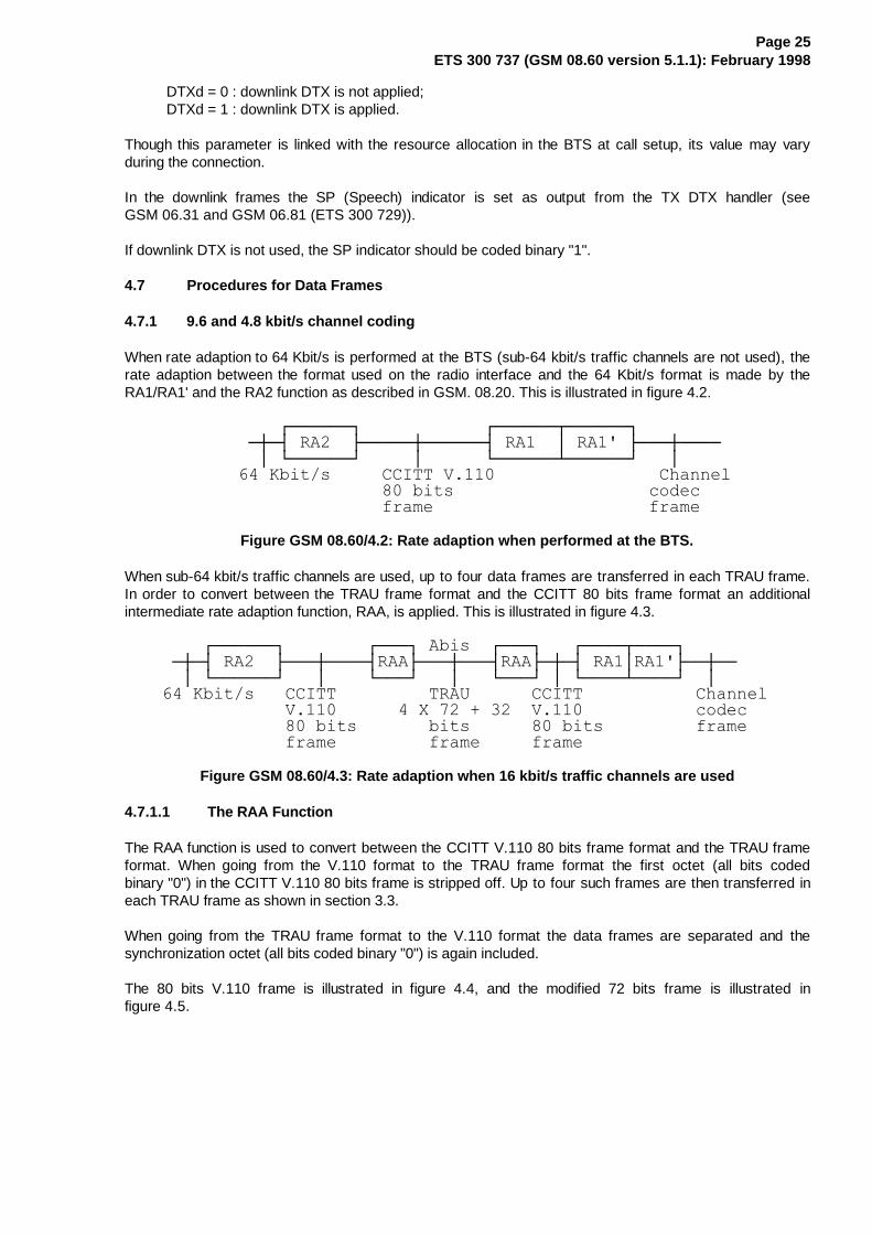
When rate adaption to 64 Kbit/s is performed at the BTS (sub-64 kbit/s traffic channels are not used), therate adaption between the format used on the radio interface and the 64 Kbit/s format is made by theRA1/RA1' and the RA2 function as described in GSM. 08.20. This is illustrated in figure 4.2.
�����������¸¶¶¶¶¶¶¹������������¸¶¶¶¶¶¶¾¶¶¶¶¶¶¹������������¶À¶½�5$���¼¶¶¶¶¶À¶¶¶¶¶¶½�5$���·�5$��¼¶¶¶À¶¶¶¶���������·�º¶¶¶¶¶¶»�����·������º¶¶¶¶¶¶¿¶¶¶¶¶¶»���·����������.ELW�V�����&&,77�9��������������������&KDQQHO������������������������ELWV�������������������FRGHF���������������������IUDPH���������������������IUDPH
Figure GSM 08.60/4.2: Rate adaption when performed at the BTS.
When sub-64 kbit/s traffic channels are used, up to four data frames are transferred in each TRAU frame.In order to convert between the TRAU frame format and the CCITT 80 bits frame format an additionalintermediate rate adaption function, RAA, is applied. This is illustrated in figure 4.3.
������¸¶¶¶¶¶¶¹��������¸¶¶¶¹�$ELV��¸¶¶¶¹���¸¶¶¶¶¾¶¶¶¶¹���¶À¶½�5$���¼¶¶¶À¶¶¶¶½5$$¼¶¶¶À¶¶¶½5$$¼¶À¶½�5$�·5$�¼¶¶À¶¶����·�º¶¶¶¶¶¶»���·����º¶¶¶»���·���º¶¶¶»�·�º¶¶¶¶¿¶¶¶¶»��·�����.ELW�V���&&,77���������75$8������&&,77�����������&KDQQHO��������������9������������;����������9���������������FRGHF�����������������ELWV�������ELWV���������ELWV���������IUDPH��������������IUDPH���������IUDPH�����IUDPH�������
Figure GSM 08.60/4.3: Rate adaption when 16 kbit/s traffic channels are used
4.7.1.1 The RAA Function
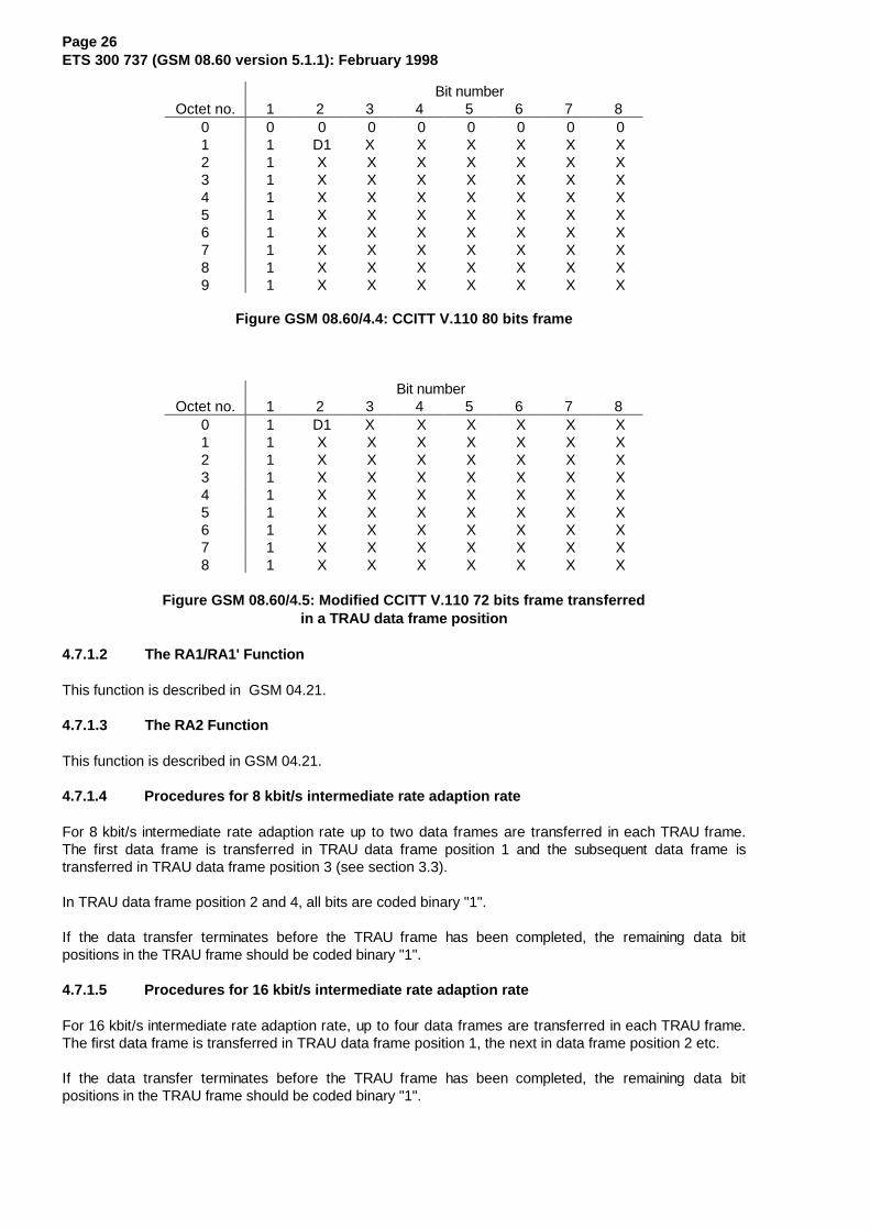
The RAA function is used to convert between the CCITT V.110 80 bits frame format and the TRAU frameformat. When going from the V.110 format to the TRAU frame format the first octet (all bits codedbinary "0") in the CCITT V.110 80 bits frame is stripped off. Up to four such frames are then transferred ineach TRAU frame as shown in section 3.3.
When going from the TRAU frame format to the V.110 format the data frames are separated and thesynchronization octet (all bits coded binary "0") is again included.
The 80 bits V.110 frame is illustrated in figure 4.4, and the modified 72 bits frame is illustrated infigure 4.5.
Page 26ETS 300 737 (GSM 08.60 version 5.1.1): February 1998
Bit number Octet no. 1 2 3 4 5 6 7 8
0 0 0 0 0 0 0 0 01 1 D1 X X X X X X2 1 X X X X X X X3 1 X X X X X X X4 1 X X X X X X X5 1 X X X X X X X6 1 X X X X X X X7 1 X X X X X X X8 1 X X X X X X X9 1 X X X X X X X
Figure GSM 08.60/4.4: CCITT V.110 80 bits frame
Bit numberOctet no. 1 2 3 4 5 6 7 8
0 1 D1 X X X X X X1 1 X X X X X X X2 1 X X X X X X X3 1 X X X X X X X4 1 X X X X X X X5 1 X X X X X X X6 1 X X X X X X X7 1 X X X X X X X8 1 X X X X X X X
Figure GSM 08.60/4.5: Modified CCITT V.110 72 bits frame transferredin a TRAU data frame position
4.7.1.2 The RA1/RA1' Function
This function is described in GSM 04.21.
4.7.1.3 The RA2 Function
This function is described in GSM 04.21.
4.7.1.4 Procedures for 8 kbit/s intermediate rate adaption rate
For 8 kbit/s intermediate rate adaption rate up to two data frames are transferred in each TRAU frame.The first data frame is transferred in TRAU data frame position 1 and the subsequent data frame istransferred in TRAU data frame position 3 (see section 3.3).
In TRAU data frame position 2 and 4, all bits are coded binary "1".
If the data transfer terminates before the TRAU frame has been completed, the remaining data bitpositions in the TRAU frame should be coded binary "1".
4.7.1.5 Procedures for 16 kbit/s intermediate rate adaption rate
For 16 kbit/s intermediate rate adaption rate, up to four data frames are transferred in each TRAU frame.The first data frame is transferred in TRAU data frame position 1, the next in data frame position 2 etc.
If the data transfer terminates before the TRAU frame has been completed, the remaining data bitpositions in the TRAU frame should be coded binary "1".

Page 27ETS 300 737 (GSM 08.60 version 5.1.1): February 1998
4.7.1.6 Support of Non-Transparent Bearer Applications
In GSM 08.20, the procedures for transfer of non-transparent bearer applications are specified. The 240bit RLP frame is converted to four modified V.110 80 bit frames.
The same conversion is applied when transferred in a TRAU frame. The frames are coded as specified insections 4.7.4 and 4.7.5.
4.7.2 14.5 kbit/s channel coding
When rate adaption to 64 Kbit/s is performed at the BTS (sub-64 kbit/s traffic channels are not used), therate adaption between the format used on the radio interface and the 64 Kbit/s format is as described inGSM 08.20.
When sub-64 kbit/s traffic channels are used, up to eight 36 bits frames are transferred in each E-TRAUframe. In order to convert between the E-TRAU frame format and the 36 bits frame format used for theradio interface an additional intermediate rate adaption function, RA1’/RAA’, is applied. This is illustrated infigure 4.3.1 (see also GSM 08.20).
������¸¶¶¶¶¶¶¹��������¸¶¶¶¶¹�$ELV���������¸¶¶¶¶¶¾¶¶¶¶¹���¶À¶½�5$���¼¶¶¶À¶¶¶¶½5$$¼¶¶¶À¶¶¶¶¶¶¶¶¶¶½�5$$·5$�¼¶¶À¶¶����·�º¶¶¶¶¶¶»���·����º¶¶¶¶»���·����������º¶¶¶¶¶¿¶¶¶¶»��·�����.ELW�V���$�75$8���������(�75$8�����������5DGLR���������������;������������������������������,QWHUIDFH���������������ELWV���������ELWV��������������IUDPH��������������IUDPH���������IUDPH������������
Figure GSM 08.60/4.3.1: Rate adaption when 16 kbit/s traffic channels are used
4.7.2.1 The RAA’ Function
See GSM 08.20
4.7.2.2 The RA1’/RAA' Function
This function is described in GSM 08.20.
4.7.2.3 The RA2 Function
This function is described in GSM 04.21.
4.8 Frame Synchronization
4.8.1 Search for Frame Synchronization
The frame synchronization is obtained by means of the first two octets in each frame, with all bits codedbinary "0", and the first bit in octet no. 2, 4, 6, 8, ... 38 coded binary "1". The following 35 bit alignmentpattern is used to achieve frame synchronization:
�������������������;;;;;;;�;;;;;;;;��;;;;;;;�;;;;;;;;��;;;;;;;�;;;;;;;;�;;;;;;;�;;;;;;;;��;;;;;;;�;;;;;;;;��;;;;;;;�;;;;;;;;��;;;;;;;�;;;;;;;;�;;;;;;;�;;;;;;;;��;;;;;;;�;;;;;;;;��;;;;;;;�;;;;;;;;��;;;;;;;�;;;;;;;;�;;;;;;;�;;;;;;;;��;;;;;;;�;;;;;;;;��;;;;;;;�;;;;;;;;��;;;;;;;�;;;;;;;;�;;;;;;;�;;;;;;;;��;;;;;;;�;;;;;;;;��;;;;;;;�;;;;;;;;��;;;;;;;�;;;;;;;;
4.8.2 Frame Synchronization After Performing Downlink Timing Adjustments
If the timing of the downlink speech frames is adjusted, the adjustment is indicated in bits C6 - C11 asdescribed in sections 4.6.1.1 and 4.6.1.2. The frame synchronization unit shall change its framesynchronization window accordingly.

Page 28ETS 300 737 (GSM 08.60 version 5.1.1): February 1998
4.8.3 Frame Synchronization Monitoring and Recovery
The monitoring of the frame synchronization shall be a continuous process.
Loss of frame synchronization shall not be assumed unless at least three consecutive frames, each with atleast one framing bit error, are detected.
In case of Full Rate speech:
If the TRAU looses its frame synchronization it starts a timer Tsync = 1 second. If Tsync expiresbefore frame synchronization is again obtained the TRAU initiates sending of the urgent alarmpattern described in section 4.10.2.
The exception from this procedure is when "Resource Release" is detected while Tsync is running(see section 4.3). In this case, the procedure in section 4.3 shall be followed.
If loss of frame synchronization is detected by the CCU it starts a timer Tsync. If Tsync expiresbefore frame synchronization is again obtained the call shall be released and an indication given toO&M.
Tsync is reset every time frame synchronization is again obtained.
In case of Enhanced full rate speech:
When it detects a framing bit error, the TRAU uses the control bit UFE (uplink Frame Error) in thenext downlink TRAU frame to indicate it to the CCU. When the CCU receives a TRAU frameindicating an Uplink Frame Error and which has no errors on the sychronization pattern and thecontrol bits, it starts a timer TsyncU.
If loss of frame sychronization is detected by the CCU it starts a timer TsyncD. If TsyncD or TsyncUexpires before frame sychronization is again obtained, the call shall be released as specified inGSM 08.58 with the case field set to " Remote Transcoder Failure".
TsyncD is reset every time frame synchronisation is again obtained.
TsychU is reset every time three consecutive TRAU frames are received without Uplink Frame Errorindication, without errors on the frame synchronisation pattern and on the control bits.
TsyncD and TsyncU are parameters set by O&M (default value = 1 second).
In case of Data 14.5 kbit/s:
The following 17 bit alignment pattern of the Extended Data TRAU Frame is used for FrameSynchronization Monitoring:
�������������������;;;;;;;�;;;;;;;;�;;;;;;;;�;;;;;;;;�;;;;;;;;�;;;;;;;;;;;;;;;;�;;;;;;;;�;;;;;;;;�;;;;;;;;�;;;;;;;;�;;;;;;;;�;;;;;;;;�;;;;;;;;;;;;;;;;�;;;;;;;;�;;;;;;;;�;;;;;;;;�;;;;;;;;�;;;;;;;;�;;;;;;;;�;;;;;;;;;;;;;;;;�;;;;;;;;�;;;;;;;;�;;;;;;;;�;;;;;;;;�;;;;;;;;�;;;;;;;;�;;;;;;;;;;;;;;;;�;;;;;;;;�;;;;;;;;�;;;;;;;;�;;;;;;;;�;;;;;;;;�;;;;;;;;�;;;;;;;;
When it detects a framing bit error, the TRAU uses the control bit UFE (uplink Frame Error) in thenext downlink Extended Data TRAU Frame to indicate it to the CCU. When the CCU receives anExtended Data TRAU Frame indicating an Uplink Frame Error and which has no errors on thesynchronization pattern and the control bits, it starts a timer TsyncU and TsyncR.
If loss of frame synchronization is detected by the CCU it starts a timer TsyncD and starts sendingData TRAU Frames in the uplink direction to trigger the TRAU to start sending Data TRAU Framesin the downlink direction to be used for downlink Synchronization Recovery.

Page 29ETS 300 737 (GSM 08.60 version 5.1.1): February 1998
If TsyncR expires before frame synchronization is again obtained, the CCU starts sending DataTRAU Frames in the uplink direction to be used for uplink Synchronization Recovery.
If TsyncD or TsyncU expires before frame synchronization is again obtained, the call shall bereleased as specified in GSM 08.58 with the case field set to " Remote Transcoder Failure".
TsyncD is reset every time frame synchronization is again obtained.
TsychU and TsyncR is reset every time three consecutive TRAU frames are received without UplinkFrame Error indication, without errors on the frame synchronization pattern and on the control bits.
TsyncD and TsyncU are parameters set by O&M (default value = 1 second)
TsyncR are a parameter set by O&M (default value = 60 milliseconds).
4.9 Correction/detection of bit errors on the terrestrial circuits
4.9.1 Error Detection on the Control Bits
For the control bits, (C-bits), no error coding is made. However, in order to reduce the possibility ofmisinterpretation of control information due to bit errors, the following procedure should be followed.
4.9.1.1 General Procedure
If any undefined combination of the C-bits is received (see section 3.5), the frame should be reacted uponas received with errors.
4.9.1.2 Speech Frames
In addition to the general procedure described in the previous section, the following procedure should befollowed for the speech frames:
Bits C6 - C11: Time Alignment.
The full range of the time alignment adjustment should only be applied when the TRAU is in the Initial TimeAlignment state (see sections 4.6.1.1 and 4.6.1.2).
If, in the Static Time Alignment state, a time alignment order is received indicating an adjustment of morethan 250 µS, the next downlink frame should be delayed only one 250 µS step.
If an uplink frame is received with the "Time Alignment" field set to an unused value (101000 ... 111101),this value should be interpreted as "no change".
4.9.2 Handling of frames received with errors
If TRAU frame is received in the uplink or downlink with detectable errors in the control bits, then thecontrol information shall be ignored. The speech or data bits shall be handled as if no error had beendetected.
If frame synchronisation has been lost (see section 4.8.3) in the uplink direction the TRAU shall:
- for speech, mute the decoded speech as if it has received frames with errors (cf. GSM 06.11 andGSM 06.61 (ETS 300 727));
- for data, send idle frames as defined in GSM 08.20 to the MSC/interworking.
4.9.2.1 In case of Full Rate:
If frame synchronisation has been lost in the downlink direction then the same procedure shall be followedas when frame synchronisation is lost on the PCM link.

Page 30ETS 300 737 (GSM 08.60 version 5.1.1): February 1998
4.9.2.2 In case of Enhanced Full rate:
For speech calls, the CCU shall transmit a layer two fill frame on the air interface if frame synchronizationhas been lost in the downlink direction.
If a CRC error is detected in a downlink TRAU speech frame a solution can be to transmit a layer two fillframe on the air interface, another solution can be to replace the bad part of the TRAU speech frame only.The choice of the solution is left open.
If a CRC error is detected in a uplink TRAU speech frame, the TRAU speech frame shall be regarded asbad or partly bad and the TRAU shall apply the procedure defined in GSM 06.61 (ETS 300 727).
4.10 Procedures for Operation & Maintenance
The general procedures for Operation and Maintenance are described in GSM 12.21.
If the transcoders are positioned outside the BTS, some O&M functions will be required for the TRAU andthe CCU. In particular this applies for transcoders positioned at the MSC site.
The transcoders outside the BTS are considered a part of the BSC, and the O&M functions for the TRAUshould therefore be implemented in the BSC.
The CCU is a part of the BTS and the O&M functions for this unit should therefore be implemented in theBTS.
4.10.1 Transfer of O&M Information Between the TRAU and the BSC
The transfer of O&M information between the BSC and the TRAU is possible to do in two ways. Either it ishandled directly between the BSC and the TRAU or a BTS is used as a message transfer point. Thechoice between the two methods is up to the manufacturer of the BSC:
i) The transfer of O&M information between the BSC and the TRAU is handled internally by the BSC.The O&M signalling between the TRAU and the BSC may either be handled by proprietary BSCsolutions or the O&M TRAU frames defined in sections 3.2 and 3.5.2 could be used. In the lattercase, the BSC has to act as a terminal for the O&M TRAU frames sent between the TRAU and theBSC.
ii) The O&M information between the TRAU and the BSC is transferred using O&M TRAU framesbetween the TRAU and the CCU in a BTS. The BTS then acts as a relay function between the O&MTRAU frames and the associated O&M messages sent between the BTS and the BSC.
4.10.2 Procedures in the TRAU
In case of urgent fault conditions in the TRAU, e.g. loss of frame synchronization, non-ability of thetranscoder to process data etc., this should if possible, be signalled to the BTS/BSC as an urgent alarmpattern. The urgent alarm pattern is a continuous stream of binary "0".
If O&M TRAU frames information between the TRAU and the BSC is transferred using O&M framesbetween the CCU in a BTS and the TRAU, the TRAU sends O&M frames periodically until the identicalO&M TRAU frame is received for acknowledgement. The period is at least 64*20ms (1,28 sec).
In case of minor fault conditions, when no immediate action is required, the TRAU may send O&M framesindicating the fault instead of the urgent alarm pattern.
4.10.3 Procedures in the BSC
The BSC should be able to detect a faulty TRAU, take it out of service and give an indication to O&M. Afaulty TRAU could be detected e.g. by routine tests, alarms from the TRAU, release of call initiated by theBTS due to remote transcoder failure etc. How this is handled by the BSC is regarded as a BSC internalmatter.

Page 31ETS 300 737 (GSM 08.60 version 5.1.1): February 1998
4.10.3.1 Use of O&M Frames
The use and coding of O&M TRAU frames is left to the implementor of the BSC/TRAU.
If O&M TRAU frames are used, they are always carrying 264 data bits.
Any corresponding O&M message between the BSC and the BTS shall always carry all 264 O&M databits.
4.10.4 Procedures in the BTS
If a CCU in a BTS receives O&M TRAU frames from the TRAU, the BTS shall:
- send the identical frame to the TRAU for acknowledgement; and
- put the 264 data bits from the received frames into an appropriate O&M message and send it to theBSC.
If the CCU receives O&M frames during a call then "stolen frames" shall be indicated to the MS and layer2 frames of format A (see GSM 04.06) shall be transmitted.
If the CCU receives O&M frames during a data call, then the same procedure shall be used as when V.110frame is lost.
If receiving an O&M message from the BSC, carrying TRAU O&M information, the BTS puts the 264 databits from the received message into an O&M TRAU frame and then the CCU allocated to the addressedconnection sends the frame to the TRAU in one single O&M TRAU frame. Repetition is done according toGSM 12.21.
In case of a faulty CCU, the O&M procedures are BTS internal.
If the CCU receives the urgent alarm pattern, the BTS shall initiate release of the call as specified in GSM08.58 with the cause field set to "Remote Transcoder Failure".

Page 32ETS 300 737 (GSM 08.60 version 5.1.1): February 1998
History
Document history
March 1996 Public Enquiry PE 104: 1996-03-25 to 1996-08-16
November 1996 Vote V 115: 1996-11-25 to 1997-01-17
March 1997 First Edition
September 1997 One-step Approval Procedure OAP 9803: 1997-09-19 to 1998-01-16(Second Edition)
February 1998 Second Edition
ISBN 2-7437-2001-8Dépôt légal : Février 1998