european gnss contingency/reversion handbook for pbn … · 2019-04-15 · rnav 1 infrastructure...
TRANSCRIPT
1
European GNSS Contingency/Reversion Handbook for PBN Operations
Scenarios and Options
PBN HANDBOOK No. 6.
PBN HANDBOOK No. 6
Edition No. : Draft v.0.3
Edition Date : 01FEB2019
Status : NSG Document under development.
Intended Audience : EUROCONTROL Stakeholder Groups
-

2
This document is one of a series of PBN Handbooks which are inter-related but can each be
used independently. Handbooks 1-3-7 are mainly aimed at ATM / operational audiences,
whilst Handbooks 2 & 4 are primarily aimed at Infrastructure Managers. Handbooks 5 & 6,
provide the link between the two audiences on subjects of common importance.
This document is Handbook No 6.
For more information please contact
Contact the NAV User Support Cell :
EUROCONTROL: DECMA/RTD/CNS Evolution Unit
www.trainingzone.eurocontrol.int – in particular
Training Catalogue ‘+ Navigation’
Direct Access Modules – General ‘PBN Awareness Package’
3
DOCUMENT CONTROL
The following table records the complete history of the successive editions of the present document.
DRAFT
Edition
Number Edition Date Reason for Change Pages Affected
0.1 Q1/2018 Creation of the document All
0.2 Q3/2018 Revision of document All
0.3 Q1/2019 Revision of document following NSG
Webex 26 November 2018 All
4
EXECUTIVE SUMMARY Context
As the EU regulations related to PBN clearly indicate that GNSS is to become the primary navigation infrastructure over the next decade, this document sets out what States need to consider if the signals from primary infrastructure are degraded or lost. . (See EC Regulation No 716 of 2014 (PCP IR ATM #1; ATM #3), and EC Regulation No 1048 of 2018 (PBN IR)). Article 6 of the PBN IR requires ANSP to ensure the availability of contingency measures in the event of GNSS failure, or failure of other means needed to enable PBN Operations. Related SESAR research also identified a need for guidance material for ANSPs on how to develop a minimum operational network [MON] of VOR/DME. This document has been produced under the auspices of the Navigation Steering Group (NSG), which reports to both the Network Operations Team (NETOPS) and the Communication, Navigation and Surveillance Team (CNS-T).
Purpose
This document addresses the topic of GNSS Reversion/Contingency in the context of PBN operations. The main emphasis is placed on terminal and extended terminal operations in a surveillance environment. Operations in a non- ATS surveillance environment as well those in the Final Approach are also covered for completeness This document is not intended to be a definitive guide to contingency operations for PBN. Rather, its explanatory nature and use of sample scenarios are provided as a ‘starter pack’ for ANSPs and regulators to assist in their deliberations when planning contingency operations for GNSS reversion. It serves as a bridge document between existing EUROCONTROL guidance material already published to support Airspace Planners and Infrastructure Planners implementing PBN. This document is deliberately not detailed: it seeks rather to enhance understanding on the shared challenge of providing for GNSS contingency/reversion. Scope & Timelines
The first obligation on ANSPs stemming from the PBN IR is in December 2020 with a second obligation set for 2024. By 2040, this regulation requires GNSS to be the central positioning source for PBN. Because single-frequency single-constellation (SF-SC) i.e. GPS L1, will be the most prevalent form of GNSS positioning used up to and beyond 2030, dual-frequency multi-constellation (DF-MC) is out of this document’s scope. Thus, dual-frequency multi-constellation or the loss of one out of several frequencies or the loss of one out of several constellations is not covered in this document. In context, the expression GNSS when used in this document means the GPS core constellation (only) as well as SBAS, depending on the context.
Recommendations:
ANSPs are encouraged to develop Reversion Scenarios and associated Contingency Procedures in the event of a GNSS outage in order to ensure compliance with Articles 3-6 of the PBN IR to meet applications specified for the three step target dates of 2020, 2024 and 2030 described in Article 7 of the PBN IR.
5
TABLE OF CONTENTS
1. CONTEXT ........................................................................................................................ 10
1.1 Regulatory Context ............................................................................................................... 10
1.2 PBN Positioning .................................................................................................................... 10
1.3 Regulatory (and Positioning) step-change .......................................................................... 12
1.4 Summary............................................................................................................................... 12
2. GPS OUTAGE IMPACT ...................................................................................................... 13
2.1 INTRODUCTION .................................................................................................................... 13
2.2 THE VOCABULARY CHALLENGE ............................................................................................ 13
2.3 OUTAGE – MITIGATION - CONTINGENCY ............................................................................. 16
2.3.1 Regulatory Impact ........................................................................................................ 16
2.4 Summary............................................................................................................................... 20
3. SCENARIOS FOR GNSS CONTINGENCY / REVERSION ........................................................ 21
3.1 Introduction .......................................................................................................................... 21
3.2 CNS trade-offs ...................................................................................................................... 22
3.3 Scenarios continental Terminal and Extended Terminal ..................................................... 22
3.3.1 Scenario for High Density continental Terminal and Extended Terminal ..................... 24
3.3.2 Scenario for High Density continental Terminal and Extended Terminal ..................... 26
3.3.3 Scenarios for Medium-Density continental Terminal and Extended Terminal ............. 28
3.3.4 Scenarios for Low-Density continental Terminal and Extended Terminal .................... 30
4. PROCESS FOR CONTINGENCY SCENARIO DEVELOPMENT ................................................. 33
4.1 DEVELOPMENT OF A VOR(/DME) MON ............................................................................... 36
4.1.1 Residual operational roles of VOR ................................................................................ 36
4.1.2 VOR(/DME) MON Design Process ................................................................................. 37
5. CONCLUSION .................................................................................................................. 41
Appendix 1/3: Impact of GPS Outage on airborne and ground Systems
Appendix 2/3: Budapest Simulation Summary (2014)
Appendix 3/3: Impact of GPS outage on SUR (re PCP airports)

6
7
ABBREVIATIONS
4D 4-dimensional
ADS-B
A-PNT
Automatic Dependent Surveillance- Broadcast
Alternative Positioning Navigation and Timing
APV Approach Procedure with Vertical Guidance
APV-Baro Approach Procedure with Vertical Guidance with Barometric Vertical Guidance
APV-SBAS Approach Procedure with Vertical Guidance with Satellite Based Augmentation
AR Authorisation Required
B-RNAV Basic Area Navigation (RNAV 5)
CS-ACNS Certification Specification for Airborne CNS
D/D DME/DME
DME Distance Measuring Equipment
EGNOS European Geostationary Navigation Overlay Service
FAS Final Approach Segment
FL Flight Level
FMS Flight Management System
FRT Fixed-Radius Transition
GBAS Ground Based Augmentation System
GNSS Global Satellite Navigation System
GPS Global Positioning System
ICAO International Civil Aviation Organization
ILS Instrument Landing System
IRU Inertial Reference Unit
PALS Precision Approach and Landing System
LOA Letter of Acceptance
LNAV Lateral Navigation
LNAV/VNAV Lateral Navigation/Vertical Navigation
LP Lateral Precision
LPV Lateral Precision with Vertical Guidance
MASPS Minimum Aviation System Performance Standards
MC Multi Constellation
MF Multi Frequency
MLS Microwave Landing System
MoC
MON
Means of Compliance
Minimum Operational Network
MOPS Minimum Operational Performance Standards
NAV Navigation
NAVAID Navigation Aid
NM Nautical Mile
NPA Non Precision Approach

8
NPR Noise Preferential Routes
NSA National Supervisory Authority
PA Precision Approach
PANS Procedures of Air Navigation Services
PBN Performance-Based Navigation
PBN SG Performance-Based Navigation Study Group
PIRG Planning and Implementation Regional Group
P-RNAV Precision Area Navigation (≈ RNAV 1)
PRB Performance Review Body
PRC Performance Review Commission
RF Radius to Fix
RNAV Area Navigation
RNP Required Navigation Performance
RNP APCH Required Navigation Performance Approach
RTA Required Time of Arrival
RTCA Radio Technical Commission for Aeronautics
SARPS Standards And Recommended Practices
SBAS Satellite Based Augmentation System
SID Standard Instrument Departure
SIS Signal In Space
SPA Specific Approval
SPI Surveillance Performance and Interoperability
STAR
TACAN
Standard Instrument Arrival Route
Tactical Air Navigation System
TBO Trajectory Based Operations
TMA Terminal Control Area
TOAC Time of Arrival Control
TPO Tactical Parallel Offset
TSO Technical Standard Order
US United States
VOR Very-High Frequency (VHF) Omni-directional Radio Range
VORTAC Very-High Frequency (VHF) Omni-directional Radio Range/Tactical Air Navigation System
VNAV Vertical Navigation
WG Working Group
xLS Precision landing system such as ILS, GLS, MLS
9
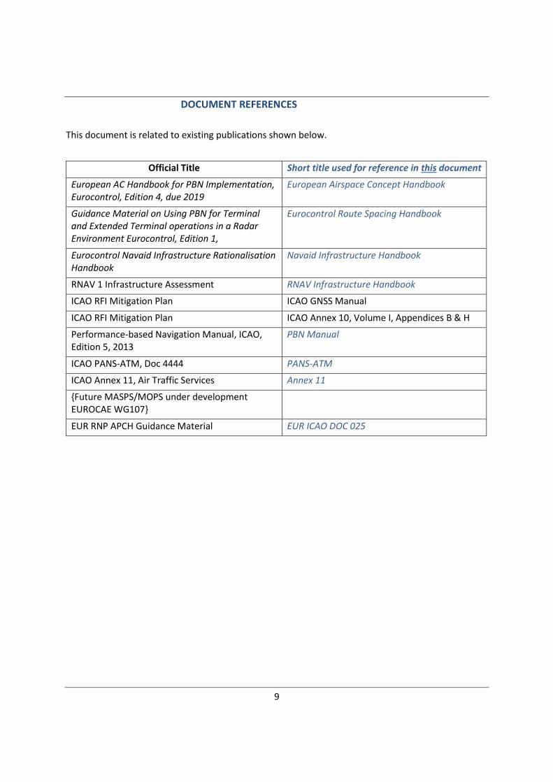
DOCUMENT REFERENCES
This document is related to existing publications shown below.
Official Title Short title used for reference in this document
European AC Handbook for PBN Implementation, Eurocontrol, Edition 4, due 2019
European Airspace Concept Handbook
Guidance Material on Using PBN for Terminal and Extended Terminal operations in a Radar Environment Eurocontrol, Edition 1,
Eurocontrol Route Spacing Handbook
Eurocontrol Navaid Infrastructure Rationalisation Handbook
Navaid Infrastructure Handbook
RNAV 1 Infrastructure Assessment RNAV Infrastructure Handbook
ICAO RFI Mitigation Plan ICAO GNSS Manual
ICAO RFI Mitigation Plan ICAO Annex 10, Volume I, Appendices B & H
Performance-based Navigation Manual, ICAO, Edition 5, 2013
PBN Manual
ICAO PANS-ATM, Doc 4444 PANS-ATM
ICAO Annex 11, Air Traffic Services Annex 11
{Future MASPS/MOPS under development EUROCAE WG107}
EUR RNP APCH Guidance Material EUR ICAO DOC 025
__REV GM on RNP Contigency and GNSS Reversion_19MAR2019_fp.docx
10
1. CONTEXT
1.1 Regulatory Context
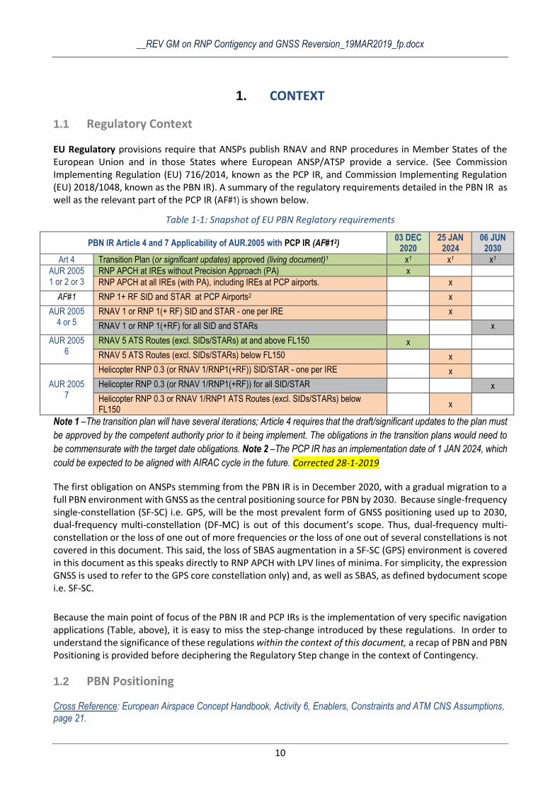
EU Regulatory provisions require that ANSPs publish RNAV and RNP procedures in Member States of the European Union and in those States where European ANSP/ATSP provide a service. (See Commission Implementing Regulation (EU) 716/2014, known as the PCP IR, and Commission Implementing Regulation (EU) 2018/1048, known as the PBN IR). A summary of the regulatory requirements detailed in the PBN IR as well as the relevant part of the PCP IR (AF#1) is shown below.
Table 1-1: Snapshot of EU PBN Reglatory requirements
PBN IR Article 4 and 7 Applicability of AUR.2005 with PCP IR (AF#12) 03 DEC
2020 25 JAN
2024 06 JUN
2030
Art 4 Transition Plan (or significant updates) approved (living document)1 x1 x1 x1
AUR 2005 1 or 2 or 3
RNP APCH at IREs without Precision Approach (PA) x
RNP APCH at all IREs (with PA), including IREs at PCP airports. x
AF#1 RNP 1+ RF SID and STAR at PCP Airports2 x
AUR 2005 4 or 5
RNAV 1 or RNP 1(+ RF) SID and STAR - one per IRE x
RNAV 1 or RNP 1(+RF) for all SID and STARs x
AUR 2005 6
RNAV 5 ATS Routes (excl. SIDs/STARs) at and above FL150 x
RNAV 5 ATS Routes (excl. SIDs/STARs) below FL150 x
AUR 2005 7
Helicopter RNP 0.3 (or RNAV 1/RNP1(+RF)) SID/STAR - one per IRE x
Helicopter RNP 0.3 (or RNAV 1/RNP1(+RF)) for all SID/STAR x
Helicopter RNP 0.3 or RNAV 1/RNP1 ATS Routes (excl. SIDs/STARs) below FL150
x
Note 1 –The transition plan will have several iterations; Article 4 requires that the draft/significant updates to the plan must
be approved by the competent authority prior to it being implement. The obligations in the transition plans would need to
be commensurate with the target date obligations. Note 2 –The PCP IR has an implementation date of 1 JAN 2024, which
could be expected to be aligned with AIRAC cycle in the future. Corrected 28-1-2019
The first obligation on ANSPs stemming from the PBN IR is in December 2020, with a gradual migration to a full PBN environment with GNSS as the central positioning source for PBN by 2030. Because single-frequency single-constellation (SF-SC) i.e. GPS, will be the most prevalent form of GNSS positioning used up to 2030, dual-frequency multi-constellation (DF-MC) is out of this document’s scope. Thus, dual-frequency multi-constellation or the loss of one out of more frequencies or the loss of one out of several constellations is not covered in this document. This said, the loss of SBAS augmentation in a SF-SC (GPS) environment is covered in this document as this speaks directly to RNP APCH with LPV lines of minima. For simplicity, the expression GNSS is used to refer to the GPS core constellation only) and, as well as SBAS, as defined bydocument scope i.e. SF-SC.
Because the main point of focus of the PBN IR and PCP IRs is the implementation of very specific navigation applications (Table, above), it is easy to miss the step-change introduced by these regulations. In order to understand the significance of these regulations within the context of this document, a recap of PBN and PBN Positioning is provided before deciphering the Regulatory Step change in the context of Contingency.
1.2 PBN Positioning
Cross Reference: European Airspace Concept Handbook, Activity 6, Enablers, Constraints and ATM CNS Assumptions, page 21.
__REV GM on RNP Contigency and GNSS Reversion_19MAR2019_fp.docx
11
The PBN Concept is comprised of three elements:
- The Navigation Specification (which provides the certification/operational standards for the RNAV
or RNP application)
- The Navaid Infrastructure (which provides the positioning for the required RNAV or RNP
specification)
- The Navigation Application which is the use of the Navigation Specification and Infrastructure
together in the form of Routes, SIDS/STARs and Instrument Approach Procedures
Whilst PBN relies on the use of an area navigation (RNAV) system for navigation, positioning is provided to an aircraft’s RNAV system by any of the following means, which may be used in combination:
(i) the space-based Navaid Infrastructure (GNSS, in this case, GPS &and SBAS);
(ii) ground-based Navaids (DME/DME, VOR/DME); or
(iii) an on-board inertial reference system periodically updated by the space- or ground-based infrastructure.
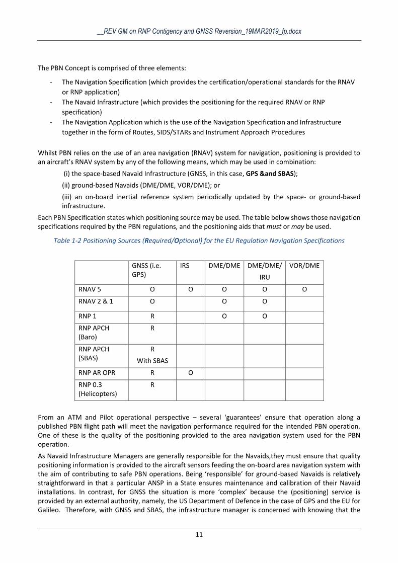
Each PBN Specification states which positioning source may be used. The table below shows those navigation specifications required by the PBN regulations, and the positioning aids that must or may be used.
Table 1-2 Positioning Sources (Required/Optional) for the EU Regulation Navigation Specifications
GNSS (i.e. GPS)
IRS DME/DME DME/DME/
IRU
VOR/DME
RNAV 5 O O O O O
RNAV 2 & 1 O O O
RNP 1 R O O
RNP APCH (Baro)
R
RNP APCH (SBAS)
R
With SBAS
RNP AR OPR R O
RNP 0.3 (Helicopters)
R
From an ATM and Pilot operational perspective – several ‘guarantees’ ensure that operation along a published PBN flight path will meet the navigation performance required for the intended PBN operation. One of these is the quality of the positioning provided to the area navigation system used for the PBN operation.
As Navaid Infrastructure Managers are generally responsible for the Navaids,they must ensure that quality positioning information is provided to the aircraft sensors feeding the on-board area navigation system with the aim of contributing to safe PBN operations. Being ‘responsible’ for ground-based Navaids is relatively straightforward in that a particular ANSP in a State ensures maintenance and calibration of their Navaid installations. In contrast, for GNSS the situation is more ‘complex’ because the (positioning) service is provided by an external authority, namely, the US Department of Defence in the case of GPS and the EU for Galileo. Therefore, with GNSS and SBAS, the infrastructure manager is concerned with knowing that the
__REV GM on RNP Contigency and GNSS Reversion_19MAR2019_fp.docx
12
GNSS and or SBAS is working, when it cannot be used and ensuring that GNSS vulnerabilities are properly mitigated.
It is critically important to safe operations, that ATM and Infrastructure work together closely to ensure that an appropriate level of positioning is provided for PBN operations, which allows the Infrastructure manager to assess the MON (minimum operational network) of the ground based navaidsNavaids, to be provided.
1.3 Regulatory (and Positioning) step-change
Cross Reference: European Airspace Concept Handbook, Activities 6 & 7, Enablers, Constraints and ATM CNS Assumptions, page 21 et seq.
Cross Reference: Eurocontrol Route Spacing Handbook, Chapter 1.
Extensive use is still made of vectoring in today’s operations. A transition period is envisaged from the current mix of vectoring, conventional and RNAV ATS Routes or SID/STARs and operations based on a mix of ground-based and space-based infrastructure to a total PBN environment, predicated primarily on GNSS by 2030 . This total PBN environment will be predicated on either RNAV or RNP operations, which are reliant on GNSS as the primary positioning source, with minimal conventional routes or radar vectoring.
This transition towards the new ‘norm’ scheduled for June 2030 affects several PBN stakeholders, including:
- Air traffic controllers who will need to adapt to controlling traffic less tactically (less vectoring) and rely more on the strategic de-confliction of pre-defined routes published in the airspace structure. (See EUROCONTROL Route Spacing Handbook).
- Procedure designers who may need to use different obstacle criteria when designing procedures.
- ATC system managers who will be potentially affected by the need to generate adaptations to their systems should an implementation safety case demonstrate the need for controllers to be informed of the area outage, its location and dimensions.
- Infrastructure Managers who will place GNSS at the ‘centre’ of the infrastructure stage – and ensure that there are adequate ground-based Navaids to support operations through the transition through to the end state and to support contingency operations in both instances, should the need arise.
The step-change triggered by the two PBN regulations should not be under-estimated in terms of GPS being placed at the centre of the positioning stage. What this ‘position shift’ means is that a GNSS outage could have considerable impact, given that it is to become central to PBN, and is also used for some Communication and Surveillance applications (e.g. time stamping and ADS-B surveillance, respectively). This means that contingency procedures are needed in the case of a reversion from GNSS.
1.4 Summary
This chapter has provided a snapshot of the regulatory requirements, highlighted the resulting step-change, and provided a refresher on the significance of GPS positioning for PBN operations particularly in light of the step change triggered by the PBN regulatory instruments and because GPS is a shared ‘resource’, also used by some surveillance and communication services. The next Chapter discusses the Impact of GNSS outage.
What are strategically de-conflicted procedures?
Because PBN allows SIDs/STARs to be placed (almost) anywhere, airspace designers layout PBN flight paths so as to ensure that the aircraft operating on those paths will be ‘automatically’ separated from each other. This is a great PBN benefit.
__REV GM on RNP Contigency and GNSS Reversion_19MAR2019_fp.docx
13
2. GPS OUTAGE IMPACT
2.1 INTRODUCTION
The key goal of the PBN IR is to have an exclusive PBN environment based primarily on GPS for positioning by 2030. With GPS central to these end-state PBN operations, a GPS outage could have significant impact. In some cases, an SBAS outage can also have a significant impact.
But to understand GPS outage and its impact, it is important first to ensure that the vocabulary associated with this discussion is understood by the two communities targeted by this handbook, namely ATCOs/Airspace Designers and Infrastructure managers. For this reason, this Chapter first ensures a common understanding of the terms used by the various communities, then discusses GPS outage and mitigation before looking at the impact of GPS outage.
2.2 THE VOCABULARY CHALLENGE
The primary goal of GNSS Contingency /Reversion is to ensure the safety of continued operations.
A challenge facing both ATCOs and Infrastructure Managers as regards contingency/reversion relates to vocabulary used by each community. Both specialists use different terms, often for the same thing, with the added complexity that few of these terms are defined by ICAO. Examples of these multiple terms are shown in bold in the text which follows. Yet, despite the absence of formal definition in many cases, it is considered useful to understand the ‘generic’ intent/meaning of these words when used.
ATM Vocabulary
The ATM community speaks of contingency, with PANS-ATM having a Chapter dedicated to contingency procedures. Operational ATCOs are heard using expressions such as contingencies, back up, fall back, reversion (plan B!). The generic meaning to be attributed to this variety of informal terms is that due to some ‘issue’, ATM operations cannot continue normally and ATCOs have to do something ‘different’. Reasons for these issues causing ‘non-normal’ situations can include equipment failure such as a glide path inoperative; partial or total surveillance system failure; depressurisation experienced by an aircraft; hijack or aircraft’s loss of navigation function. Often, contingency has a negative impact on traffic flow i.e. causing less runway or sector throughput or reduced air traffic flow rate. In this handbook, in an ATM context, this handbook will use the term contingency and contingency procedures to the extent possible.
Infrastructure
The Infrastructure community has its own collection of terms and to understand these, it is useful to recall that the link between PBN and the Navaid Infrastructure is that the Navaid Infrastructure provides a positioning service to the aircraft on PBN procedures. The Navaid Infrastructure is split into space-based infrastructure (GNSS, which includes GPS, BeiDou, Galileo, Glonass, in the future, and SBAS) and ground-based Navaid infrastructure which includes DME, VOR, ILS, where DME/DME can provide positioning for RNAV 1 and RNAV 5, and VOR/DME can provide positioning for RNAV 5. Conventional navigation relies only on the use of ground-based Navaids.
Within the context of contingency/reversion, infrastructure managers use the expression Reversion to refer to the need to ‘revert’ from a primary positioning system (e.g. GNSS) to the ‘backup’ system (e.g. DME/DME) when the primary system cannot be used. The increasing use of GNSS for PBN has introduced a considerable range of vocabulary related to total GNSS non-availability or its partially availability.
Alternative Position, Navigation and Timing (A-PNT) is a commonly accepted term used to refer to
what alternatives to GNSS are available when GNSS cannot be used to provide positioning for PBN.
Thus, one form of A-PNT for RNAV 1 or RNAV 5 is typically DME/DME, and for RNAV 5, VOR/DME is
possible.
__REV GM on RNP Contigency and GNSS Reversion_19MAR2019_fp.docx
14
The expression VOR/MON (VOR Minimum Operational Network), whilst not limited to the reversion
context, has grown in profile because of the consequences of extensive GNSS use. VOR/MON relates
to the minimum (number of) VORs needed in an airspace to service both normal and reversion
operations. (This notion of ‘MON’ is occasionally extended to VOR/DME MON and DME MON).
Because GNSS is vulnerable to certain threats, infrastructure managers seek to understand GNSS
vulnerability. This can be due to a constellation weakness, radio frequency interference (RFI) or
Ionospheric Interference (linked to space weather). RFI can be caused by (intentional) spoofing or
jamming or (unintentional) equipment failure or radio operator error. There is a need to mitigate
GNSS vulnerability: whilst key mitigations are achieved by placing more demands on the system
(ensuring technical resilience and robustness), there is also certain reliance on (operational
ATM/Flight crew) contingency procedures to maintain an acceptable level of safety. RFI is of greatest
significance to Contingency Procedures for GNSS reversion, as RFI is the most likely cause of GNSS
outage.
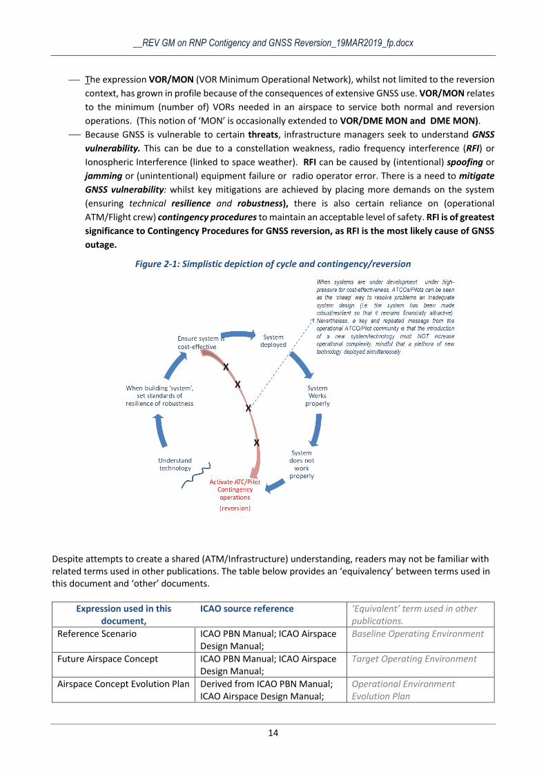
Figure 2-1: Simplistic depiction of cycle and contingency/reversion
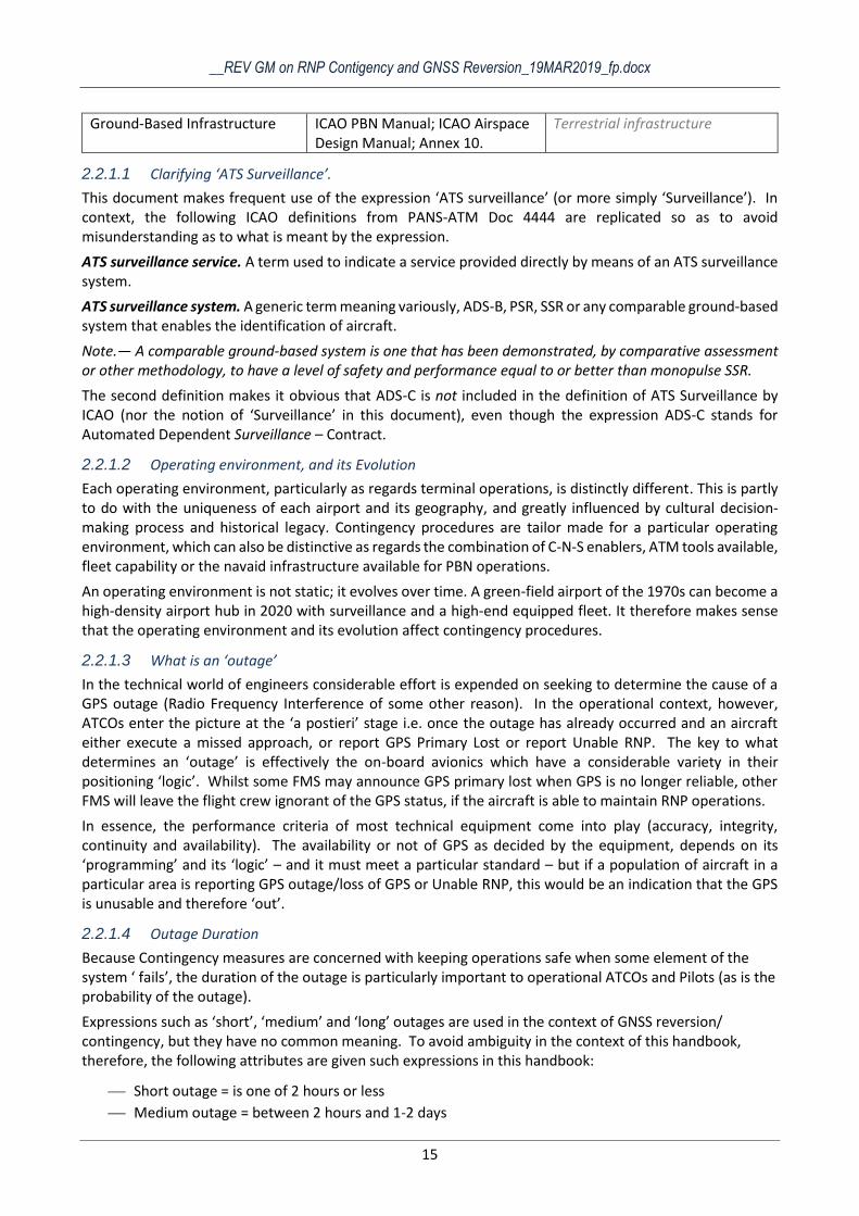
Despite attempts to create a shared (ATM/Infrastructure) understanding, readers may not be familiar with related terms used in other publications. The table below provides an ‘equivalency’ between terms used in this document and ‘other’ documents.
Expression used in this document,
ICAO source reference ‘Equivalent’ term used in other publications.
Reference Scenario ICAO PBN Manual; ICAO Airspace Design Manual;
Baseline Operating Environment
Future Airspace Concept ICAO PBN Manual; ICAO Airspace Design Manual;
Target Operating Environment
Airspace Concept Evolution Plan Derived from ICAO PBN Manual; ICAO Airspace Design Manual;
Operational Environment Evolution Plan
__REV GM on RNP Contigency and GNSS Reversion_19MAR2019_fp.docx
15
Ground-Based Infrastructure ICAO PBN Manual; ICAO Airspace Design Manual; Annex 10.
Terrestrial infrastructure
2.2.1.1 Clarifying ‘ATS Surveillance’.
This document makes frequent use of the expression ‘ATS surveillance’ (or more simply ‘Surveillance’). In context, the following ICAO definitions from PANS-ATM Doc 4444 are replicated so as to avoid misunderstanding as to what is meant by the expression.
ATS surveillance service. A term used to indicate a service provided directly by means of an ATS surveillance system.
ATS surveillance system. A generic term meaning variously, ADS-B, PSR, SSR or any comparable ground-based system that enables the identification of aircraft.
Note.— A comparable ground-based system is one that has been demonstrated, by comparative assessment or other methodology, to have a level of safety and performance equal to or better than monopulse SSR.
The second definition makes it obvious that ADS-C is not included in the definition of ATS Surveillance by ICAO (nor the notion of ‘Surveillance’ in this document), even though the expression ADS-C stands for Automated Dependent Surveillance – Contract.
2.2.1.2 Operating environment, and its Evolution
Each operating environment, particularly as regards terminal operations, is distinctly different. This is partly to do with the uniqueness of each airport and its geography, and greatly influenced by cultural decision-making process and historical legacy. Contingency procedures are tailor made for a particular operating environment, which can also be distinctive as regards the combination of C-N-S enablers, ATM tools available, fleet capability or the navaid infrastructure available for PBN operations.
An operating environment is not static; it evolves over time. A green-field airport of the 1970s can become a high-density airport hub in 2020 with surveillance and a high-end equipped fleet. It therefore makes sense that the operating environment and its evolution affect contingency procedures.
2.2.1.3 What is an ‘outage’
In the technical world of engineers considerable effort is expended on seeking to determine the cause of a GPS outage (Radio Frequency Interference of some other reason). In the operational context, however, ATCOs enter the picture at the ‘a postieri’ stage i.e. once the outage has already occurred and an aircraft either execute a missed approach, or report GPS Primary Lost or report Unable RNP. The key to what determines an ‘outage’ is effectively the on-board avionics which have a considerable variety in their positioning ‘logic’. Whilst some FMS may announce GPS primary lost when GPS is no longer reliable, other FMS will leave the flight crew ignorant of the GPS status, if the aircraft is able to maintain RNP operations.
In essence, the performance criteria of most technical equipment come into play (accuracy, integrity, continuity and availability). The availability or not of GPS as decided by the equipment, depends on its ‘programming’ and its ‘logic’ – and it must meet a particular standard – but if a population of aircraft in a particular area is reporting GPS outage/loss of GPS or Unable RNP, this would be an indication that the GPS is unusable and therefore ‘out’.
2.2.1.4 Outage Duration
Because Contingency measures are concerned with keeping operations safe when some element of the system ‘ fails’, the duration of the outage is particularly important to operational ATCOs and Pilots (as is the probability of the outage).
Expressions such as ‘short’, ‘medium’ and ‘long’ outages are used in the context of GNSS reversion/ contingency, but they have no common meaning. To avoid ambiguity in the context of this handbook, therefore, the following attributes are given such expressions in this handbook:
Short outage = is one of 2 hours or less
Medium outage = between 2 hours and 1-2 days
__REV GM on RNP Contigency and GNSS Reversion_19MAR2019_fp.docx
16
Long outage = > 2 days to 1 week
Extended outage > 1 week These (nominal) explanations of duration are only intended to serve as a short hand in this handbook. As can be seen in Appendix 2, the question of ‘duration’ was of particular relevance in the Budapest RNP 1 simulations in 2014. This study also showed that determination of a GPS outage was challenging.
Given the increasing reliance on GPS and its vulnerabilities, the element of outage duration is of considerable significance.
2.2.1.5 Outage Area
Inasmuch as outages can be of varying durations, outages can also vary in area. Some outages are localised e.g. in the direct vicinity of an approach flight path, whilst others can cover areas of different sizes, and in extreme cases, very wide areas.
2.3 OUTAGE – MITIGATION - CONTINGENCY
GPS and its augmentations are vulnerable, and such vulnerability must be mitigated either by requiring systems to be more resilient and robust, or by depending on contingency procedures which in turn may rely on alternative positioning sources or COM and/or Surveillance ensure GNSS reversion in order to maintain an acceptable level of safety.
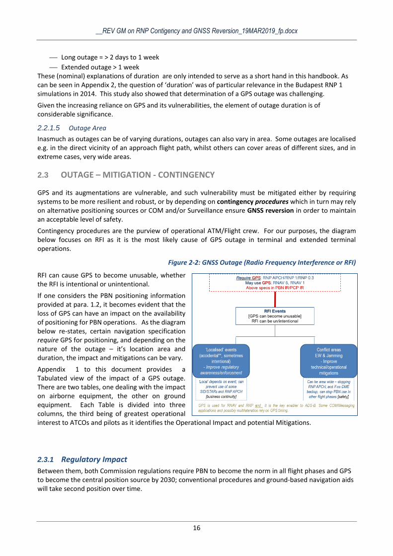
Contingency procedures are the purview of operational ATM/Flight crew. For our purposes, the diagram below focuses on RFI as it is the most likely cause of GPS outage in terminal and extended terminal operations.
Figure 2-2: GNSS Outage (Radio Frequency Interference or RFI)
RFI can cause GPS to become unusable, whether the RFI is intentional or unintentional.
If one considers the PBN positioning information provided at para. 1.2, it becomes evident that the loss of GPS can have an impact on the availability of positioning for PBN operations. As the diagram below re-states, certain navigation specification require GPS for positioning, and depending on the nature of the outage – it’s location area and duration, the impact and mitigations can be vary.
Appendix 1 to this document provides a Tabulated view of the impact of a GPS outage. There are two tables, one dealing with the impact on airborne equipment, the other on ground equipment. Each Table is divided into three columns, the third being of greatest operational interest to ATCOs and pilots as it identifies the Operational Impact and potential Mitigations.
2.3.1 Regulatory Impact
Between them, both Commission regulations require PBN to become the norm in all flight phases and GPS to become the central position source by 2030; conventional procedures and ground-based navigation aids will take second position over time.
__REV GM on RNP Contigency and GNSS Reversion_19MAR2019_fp.docx
17
Airspace Concept evolution
Operationally, the shift to PBN makes it possible to design strategically-de-conflicted SIDs/STARs or ATS Routes (in the en route network below Free Route Airspace). This may result in significantly less vectoring by 2030 [European Airspace Concept Handbook]. Moreover, RNAV 1/RNP 1 navigation performance provides the possibility to reduce the lateral spacing between routes; by 2030, a strategically de-conflicted route plan of closely spaced routes in extended terminal could be implemented. [European Airspace Concept Handbook]
For Infrastructure Managers, because PBN flight paths can be placed anywhere1 (obstacles permitting), the infrastructure managers must know where these PBN flight paths will be placed so that effective positioning coverage is made available along the flight paths for both nominal and contingency operations. [Navaid Infrastructure Handbook].
Over time, GNSS supplants conventional Navaids as the primary positioning source
Operationally, during normal operations, primary reliance on GNSS for positioning is of little relevance to the ATCO outside the final approach; In reality, the controller is mostly unaware of which positioning source is being used. If GNSS becomes unusable locally or over a wider area, the ATCO could most likely receive reports and need to know that the aircraft can continue to navigate i.e. that alternative positioning is provided e.g. using DME/DME for RNAV 1. In the Budapest Simulations it was found useful for the controllers to have an indication on their surveillance display as to which aircraft were capable of continuing navigation without GNSS.
For Infrastructure Managers, the shift to GNSS as the primary positioning source is significant: first, GNSS vulnerability mitigation increases in importance; second, it heralds a change to the evolution of the ground-based Navaid infrastructure.
As regards the first, the infrastructure manager needs to be fully aware of GNSS interference events, their causes and their impact.
Regarding the second, there is a change to the extent of the required ground-based Navaid infrastructure i.e. what MON is needed to provide the required A-PNT (see para. 2.2).
Because GNSS becomes the primary positioning source by 2030, ground-based Navaids to support normal operations are less needed over time. Ground-based Navaids must provide for GNSS reversion: a cost-effective ground-based infrastructure providing adequate redundancy must be available in the event of a GNSS outage to meet the levels of safety (and business continuity) required during contingency. Consequently,
Ground-based Navaid Infrastructure optimisation,
rationalisation and decommission opportunities
change i.e. ‘how much’ ground-based Navaid
infrastructure is needed provides opportunities to
streamline and potentially save costs.
Ground-based Navaid Infrastructure investment
decisions are affected, as are equipment life-cycles which impact upon maintenance and
replacement schedules.
1 This simplified statement is provided generically, and is not entirely accurate. It alludes to the fact that GNSS positioning is ‘usually’ available everywhere thus giving total freedom in route design (which was not the case with ground-based Navaids). However, there are places where GNSS cannot be used.
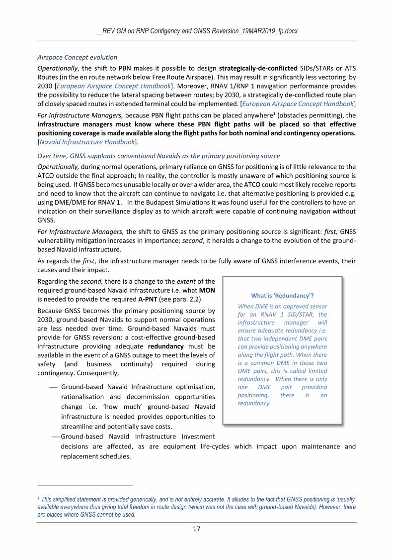
What is ‘Redundancy’?
When DME is an approved sensor for an RNAV 1 SID/STAR, the infrastructure manager will ensure adequate redundancy i.e. that two independent DME pairs can provide positioning anywhere along the flight path. When there is a common DME in those two DME pairs, this is called limited redundancy. When there is only one DME pair providing positioning, there is no redundancy.
__REV GM on RNP Contigency and GNSS Reversion_19MAR2019_fp.docx
18
2.3.1.1 Impact of the operating environment’s evolution over Time
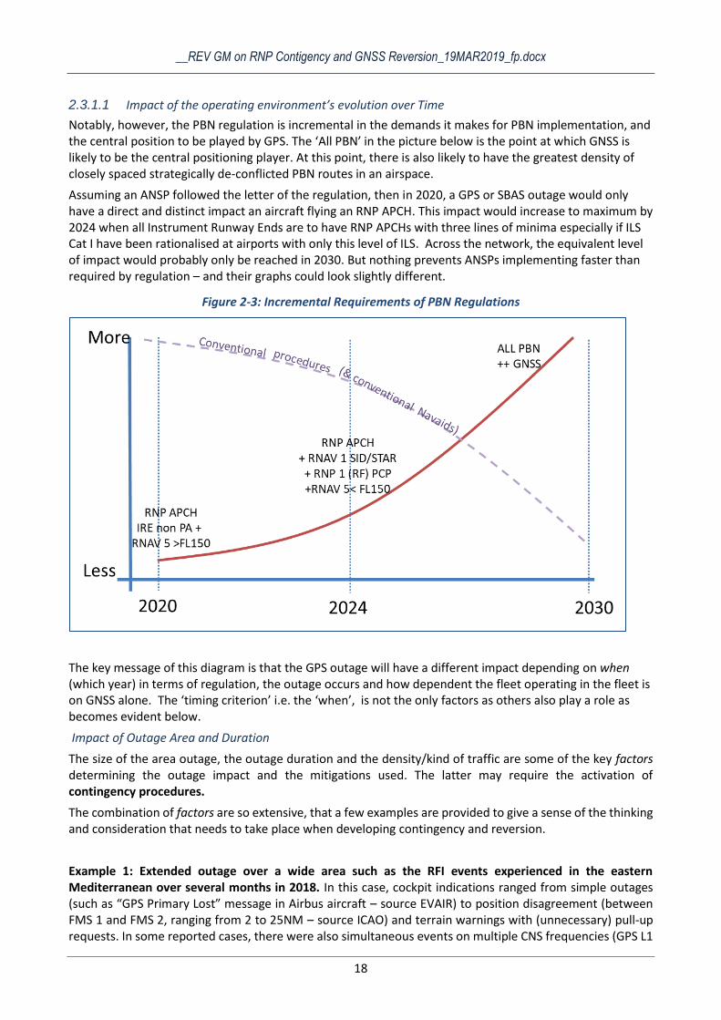
Notably, however, the PBN regulation is incremental in the demands it makes for PBN implementation, and the central position to be played by GPS. The ‘All PBN’ in the picture below is the point at which GNSS is likely to be the central positioning player. At this point, there is also likely to have the greatest density of closely spaced strategically de-conflicted PBN routes in an airspace.
Assuming an ANSP followed the letter of the regulation, then in 2020, a GPS or SBAS outage would only have a direct and distinct impact an aircraft flying an RNP APCH. This impact would increase to maximum by 2024 when all Instrument Runway Ends are to have RNP APCHs with three lines of minima especially if ILS Cat I have been rationalised at airports with only this level of ILS. Across the network, the equivalent level of impact would probably only be reached in 2030. But nothing prevents ANSPs implementing faster than required by regulation – and their graphs could look slightly different.
Figure 2-3: Incremental Requirements of PBN Regulations
The key message of this diagram is that the GPS outage will have a different impact depending on when (which year) in terms of regulation, the outage occurs and how dependent the fleet operating in the fleet is on GNSS alone. The ‘timing criterion’ i.e. the ‘when’, is not the only factors as others also play a role as becomes evident below.
Impact of Outage Area and Duration
The size of the area outage, the outage duration and the density/kind of traffic are some of the key factors determining the outage impact and the mitigations used. The latter may require the activation of contingency procedures.
The combination of factors are so extensive, that a few examples are provided to give a sense of the thinking and consideration that needs to take place when developing contingency and reversion.
Example 1: Extended outage over a wide area such as the RFI events experienced in the eastern Mediterranean over several months in 2018. In this case, cockpit indications ranged from simple outages (such as “GPS Primary Lost” message in Airbus aircraft – source EVAIR) to position disagreement (between FMS 1 and FMS 2, ranging from 2 to 25NM – source ICAO) and terrain warnings with (unnecessary) pull-up requests. In some reported cases, there were also simultaneous events on multiple CNS frequencies (GPS L1
__REV GM on RNP Contigency and GNSS Reversion_19MAR2019_fp.docx
19
and on or near the 1090 MHz SSR frequency). In general, these events are considered an operational nuisance without significant impact, however, when losing some CNS capabilities (especially over water), safety margins may be reduced and additional problems could increase risk. However, in this case, most of the aircraft operating in the area where the outage was for an extended period, were exposed to the outage area for an less than two hours. Furthermore, these air transport aircraft operating in the area have IRS to support position determination. As a consequence, the impact was mainly of nuisance value.
Example 2: ‘Localised GPS Outage’ such as those experienced by major European TMAs or the uncoordinated use of drone jammers. Often these events occur through carelessness, or use of personal privacy devices - PPD (truckers not wanting to be tracked), and in some cases, due to ‘controlled’ testing of military equipment. Even outages of short duration could cause RNP APCHs to be abandoned and possibly cause diversions. The scale of the impact would be different in 2020 than in 2024. Some SID/STARs may also be disabled, where either the SID/STAR is predicated only on GPS or the aircraft positioning capability is limited to GPS. Again, the scale of the impact would depend in when along the evolutionary timeline this problem occurs i.e. 2021 vs. 2028? Longer outages would extend the impact and may cause flow control measures to be introduced as aircraft are managed manually by Vectoring. {Note, that in the case of RNP APCH to LPV minima being prevalent at an airport, the loss of SBAS could also induce go-arounds or diversions if no reversion to ILS is possible).
Example 3. ‘Wide Area GPS Outage’ of medium duration in medium/high density airspace: - such as those tested in the Budapest RNP simulations in 2014. In these scenarios say in 2030, several aircraft operating across a number of sectors could report a GPS loss which means that exposure to the outage by each aircraft could be extensive. Of key importance to the controller in the Budapest Simulations was knowing which aircraft needed navigational assistance and which did not. (The latter were those who had no other positioning means). Whilst these controllers had the benefit of tailor made procedures, with an indication on the Surveillance Display showing which aircraft needed navigational assistance, the increased workload caused controllers’ to question whether they could sustain working ‘manually’ for more than 1.5 to 2 hours. Furthermore, a network wide impact was anticipated whereby the network manager could be required to reduce the flows of air traffic to acceptable levels for the ATC centres. Thus this kind of outage could affect traffic throughput, e.g. by preventing access for aircraft with GNSS as the only PBN position sensor, and seriously impact upon business continuity. As regards the evolutionary timeline, if this outage scenario played out in 2020 in some of the terminal areas where RNAV 1 is already implemented with significant reliance on GPS, the impact could be significant.
Example 4: Wide Area Outage of Long Duration: Given society’s dependency on GPS (which includes communication, Navigation and Surveillance systems as well as power generation systems), whether or not to continue operations in the event of a long term outage would probably be a national strategic decision.
2.3.1.2 Contingency/Reversion for RNAV 1/RNP1
Cross Reference: European Airspace Concept Handbook, Activity 7, Airspace Design – Routes & Holds, page 22.
When developing a Future Airspace Concept, ATM needs to establish how to continue safe operations in the event of GNSS no longer being usable for RNAV 1/RNP 1. Here, ATM contingency operations could be drawn from a variety of means available to ensure the safe flow of traffic (which is the prime objective). For example, including whether a surveillance service can compensate for the GNSS loss (using vectoring); or whether procedural control can be used (ATM Procedures); whether flight procedures can continue to be flown using RNAV 1 based on DME/DME positioning (A-PNT) and/or whether the traffic flow rate needs to be reduced. In determining the ‘right’ scenario for the contingency operations to be developed, it is crucial that the package of contingency procedures for an entire ATM operation are looked at together. For example:

__REV GM on RNP Contigency and GNSS Reversion_19MAR2019_fp.docx
20
if only ADS-B is used for surveillance in an particular area, it would be pointless to define contingency
procedures based on surveillance if the GPS fails, as ADS-B is reliant on the GPS position from the
aircraft and therefore the surveillance system will not be available either;
if severe weather is known to be frequent in a particular area, the contingency operations for severe
weather and those of reversion from RNAV1/RNP 1 should be considered together.
Therefore, Contingency scenarios are developed for different types of operating environments to permit operations to continue safely. These scenarios are also tested and validated.
Cross Reference: European Airspace Concept Handbook, Activity 11, Airspace Concept Validation, page 29.
Infrastructure Managers are often squeezed between what ATC needs for contingency operations and other drivers such as cost savings (to reduce the infrastructure), spectrum pressure (reducing frequencies or frequency load) or performance targets (to optimise the infrastructure). Thus they have to consider and balance contingency needs from ATM along with other requirements when determining how much infrastructure to provide for contingency.
It is therefore critical that ATM and Infrastructure Managers work together on topics related to both normal operations and contingency operations. This is a fundamental premise of successful PBN implementation.
2.4 Summary
This chapter has explained a variety of terminology, detailed positioning requirements and looked at the impact of European PBN regulatory requirements. The key conclusion to be reached is that successful contingency scenarios can only be built by ATM and Infrastructure Managers working together.
It is evident that ATM has to plan Contingency Scenarios, and the Infrastructure Mangers have to plan what reversion infrastructure will be available to support such contingency. It is therefore critical that ATM clearly communicates its requirements to the Navaid Infrastructure Manager to permit the infrastructure to be right-sized and to ensure the safety of the operational environment.
The European Airspace Concept Handbook discusses contingency as part of the development of the Future Airspace Concept. Similarly, the Navaid Infrastructure Handbook, provides guidance to Infrastructure Managers.
__REV GM on RNP Contigency and GNSS Reversion_19MAR2019_fp.docx
21
3. SCENARIOS FOR GNSS CONTINGENCY / REVERSION
3.1 Introduction
Currently, ATCOs and Infrastructure Managers have quite different perspectives on the positioning source used by aircraft operating along flight paths. In a PBN environment, the ATCO is mostly unaware which positioning source is being used in contrast to Infrastructure Managers, procedure designers and airline operators.
This chapter looks beyond 2020, at which time PBN SID/STARs and ATS routes in terminal and extended terminal operations should increasingly become the norm. It is based on the premise that systemised and strategically de-conflicted routes will have become the Future Airspace Concept.
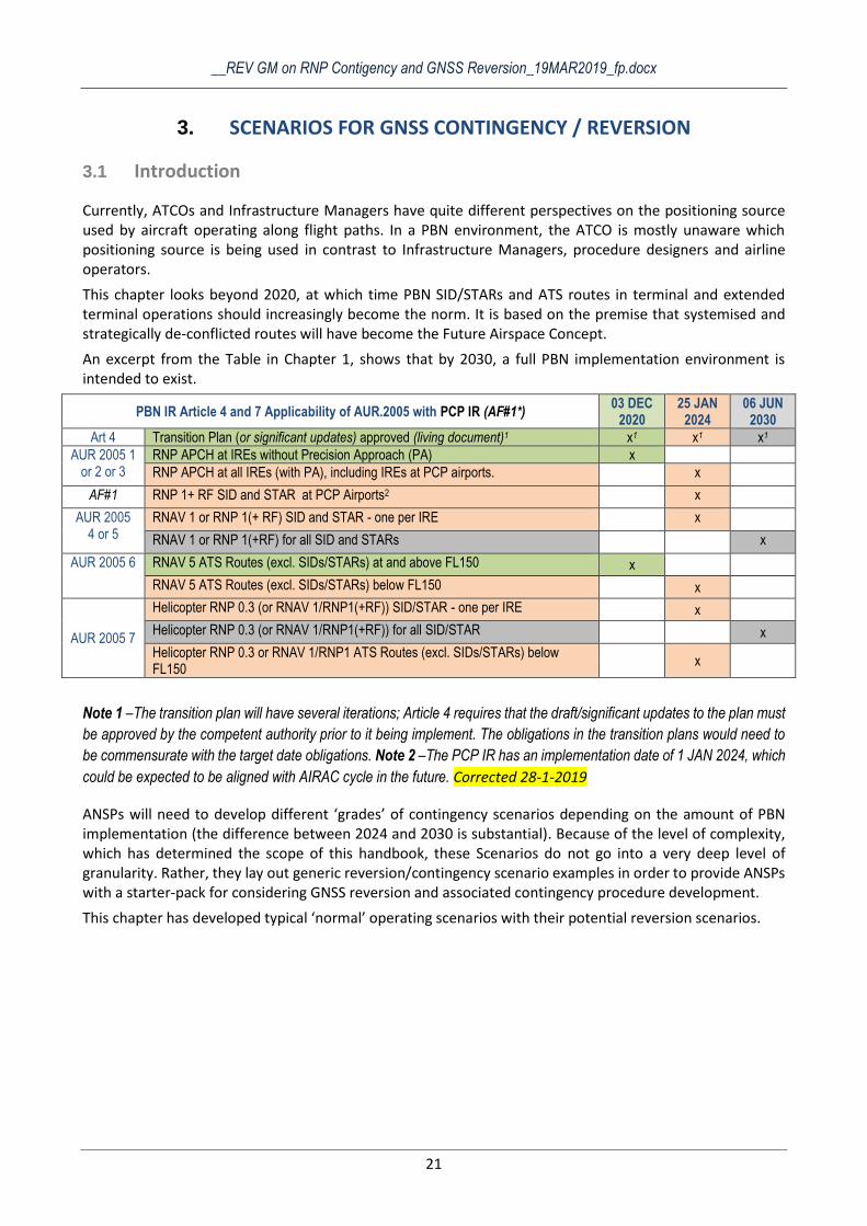
An excerpt from the Table in Chapter 1, shows that by 2030, a full PBN implementation environment is intended to exist.
PBN IR Article 4 and 7 Applicability of AUR.2005 with PCP IR (AF#1*) 03 DEC
2020 25 JAN
2024 06 JUN
2030
Art 4 Transition Plan (or significant updates) approved (living document)1 x1 x1 x1
AUR 2005 1 or 2 or 3
RNP APCH at IREs without Precision Approach (PA) x
RNP APCH at all IREs (with PA), including IREs at PCP airports. x
AF#1 RNP 1+ RF SID and STAR at PCP Airports2 x
AUR 2005 4 or 5
RNAV 1 or RNP 1(+ RF) SID and STAR - one per IRE x
RNAV 1 or RNP 1(+RF) for all SID and STARs x
AUR 2005 6 RNAV 5 ATS Routes (excl. SIDs/STARs) at and above FL150 x
RNAV 5 ATS Routes (excl. SIDs/STARs) below FL150 x
AUR 2005 7
Helicopter RNP 0.3 (or RNAV 1/RNP1(+RF)) SID/STAR - one per IRE x
Helicopter RNP 0.3 (or RNAV 1/RNP1(+RF)) for all SID/STAR x
Helicopter RNP 0.3 or RNAV 1/RNP1 ATS Routes (excl. SIDs/STARs) below FL150
x
Note 1 –The transition plan will have several iterations; Article 4 requires that the draft/significant updates to the plan must
be approved by the competent authority prior to it being implement. The obligations in the transition plans would need to
be commensurate with the target date obligations. Note 2 –The PCP IR has an implementation date of 1 JAN 2024, which
could be expected to be aligned with AIRAC cycle in the future. Corrected 28-1-2019
ANSPs will need to develop different ‘grades’ of contingency scenarios depending on the amount of PBN implementation (the difference between 2024 and 2030 is substantial). Because of the level of complexity, which has determined the scope of this handbook, these Scenarios do not go into a very deep level of granularity. Rather, they lay out generic reversion/contingency scenario examples in order to provide ANSPs with a starter-pack for considering GNSS reversion and associated contingency procedure development.
This chapter has developed typical ‘normal’ operating scenarios with their potential reversion scenarios.
__REV GM on RNP Contigency and GNSS Reversion_19MAR2019_fp.docx
22
3.2 CNS trade-offs
Cross Reference: European Airspace Concept Handbook, Activity 6, Enablers, Constraints and ATM CNS Assumptions, page 21.
Cross Reference: PBN Manual, Volume I, Part A, Chapters 1-3.
No CNS enabler single-handedly resolves all an aircraft’s technical challenges in flight. Whilst Communication, Navigation and Surveillance have historically been ‘separated’, primarily for safety and historical reasons, evolving systems are increasingly relying on the same key system i.e. GNSS.
In discussions about PBN, it often becomes evident that GNSS is used on several CNS systems, e.g. time-stamping of data transfers in message sets (COM), synchronisation of surveillance data processors (SUR), in some systems, Data Link (communication) timing (COM). These systems often have back-up timing sources or other reversion means. For back-up timing sources the outage is important where a longer outage will result in greater clock drifts. This abridged list makes it clear that GNSS is a common point, a shared resource for Communication, Navigation and Surveillance and that a GNSS outage has the potential to disrupt operations depending on how much GNSS provides the backbone of various C-N-S elements. In terms of navigation, the European fleet and Navaid Infrastructure is well equipped: Europe is fortunate to have a rich DME infrastructure and over 90% of the ECAC fleet is equipped with DME/DME RNAV capability. Thus continuing navigation as normal for a while is a feasible, though this statement is not absolute.
The remainder of this chapter contains a set of Reference Scenarios describing an Operational environment. The Reference Scenarios effectively shows what Navigation Applications are in use during normal operations, what infrastructure is available, how well equipped the fleet is, what route spacing is used, what separation minima is used based on which surveillance system and how communication is achieved. A Reference Scenario’s corresponding Contingency Scenario then ‘simulates’ GNSS not being available and indicates which parts of the operation are affected and those parts that can continue. Of course, such samples cannot and do not pretend to be complete. Their formulation is intended to assist thinking through the contingency scenario development by ANSPs.
3.3 Scenarios continental Terminal and Extended Terminal
Scenario descriptions start by showing available technology (infrastructure/avionics) followed by the supported Airspace Concept and operations. This technology based view is preferred because these scenarios deal with loss of a part of the infrastructure which then impacts upon operations.
Scenarios are named and Numbered 1-N (NORMAL OPERATIONS Scenario 1) with its corresponding 1-R (REVERSION Scenario 1), sequencing through 2-N/2-R etc.
In a REVERSION scenario:
struck out red text e.g. GNSS, indicates that the {struck-out}technology cannot be used and that as a
consequence, the {struck out} navigation function (e.g. RF) or navigation specification (e.g. RNP 0.3)
or particular route spacing (e.g. 5 NM) cannot be used either given the available CNS enablers
remaining.
Red text written in italics, e.g. RF, means that it is considered probable that there would be significant
impact in the short or medium term, thus requiring consideration when planning contingency
procedures.
Highlight text indicates what may need to become available to accommodate contingency
operations/reversion.
Explanatory notes are provided in the Reversion Scenarios.
Sample Scenarios have been selected for inclusion in this document based on PBN regulatory requirements and on known use cases. These Scenarios are prefixed H, M or L.
__REV GM on RNP Contigency and GNSS Reversion_19MAR2019_fp.docx
23
H : Scenarios for High Density/High Complexity Terminal Operations [Scenario 1 & 2]
M : Scenarios for Medium Density/Medium Complexity Terminal Operations [Scenarios 3 & 4]
L : Scenarios for Low Density Terminal Operations [Scenarios 5-6]
Mindful that referring to terminal operations having different levels of complexity or density often generates debate, particularly as some low density operations can have extremely high complexity due to lacking equipage, staffing issues, terrain challenges etc. As such, in this document has generalised, these terms are intentionally not defined, but parallels or equivalencies roughly drawn. A-B-C above as follows:
H therefore correlates to airports/operating environments targeted by the PCP IR;
M correlates roughly to non-PCP airports/operating environments having independent not
on the PCP list but catering to commercial air traffic; leaving
L for airports/operating environments not having ATS surveillance or having ADS-B surveillance only...

__REV GM on RNP Contigency and GNSS Reversion_19MAR2019_fp.docx
24
3.3.1 Scenario H1 for High Density continental Terminal and Extended Terminal
i.e. Correlates to operating environments targeted by PCP IR AF#1
Scenario Ref.H1-N: Normal Operations
NORMAL INFRASTRUCTURE
Available Navaid Infrastructure GNSS; DME; VOR/DME; VOR;
Fleet Positioning Capability for PBN GNSS + D/D > 90%
Surveillance Sensors Used At least one independent cooperative sensor (SSR or MLAT/WAM) combined with ADS-B and possibly non-cooperative sensor(s) where needed
Communication Service Used Voice; Data Link
Timing for On-Board Systems Independent + GPS Calibrated
Timing for Ground Systems Independent + GPS Calibrated
NORMAL OPERATIONS
NAV Applications enabling Airspace Concept: RNAV 5; RNAV 1; RNP 1 + RF; RNP 0.3;
Airspace Concept PBN enabled Free Routes Operations above FL 310; ATS Straight and turning parallel routes incl SID/STARs and non-parallel routes; crossing; Helicopter Routes.
Spacing between proximate PBN Routes 5 NM on straight and turning RNP 1 route segments with RF req. 5 NM on straight segments between RNAV 1 routes;
Separation Minima used in Airspace 3 NM in terminal operations;
__REV GM on RNP Contigency and GNSS Reversion_19MAR2019_fp.docx
25
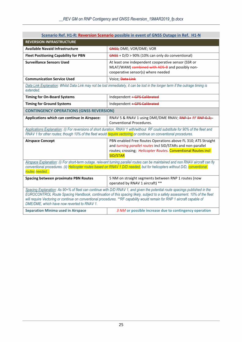
Scenario Ref. H1-R: Reversion Scenario possible in event of GNSS Outage in Ref. H1-N
REVERSION INFRASTRUCTURE
Available Navaid Infrastructure GNSS; DME; VOR/DME; VOR
Fleet Positioning Capability for PBN GNSS + D/D > 90% (10% can only do conventional)
Surveillance Sensors Used At least one independent cooperative sensor (SSR or MLAT/WAM) combined with ADS-B and possibly non-cooperative sensor(s) where needed
Communication Service Used Voice; Data Link
Data Link Explanation: Whilst Data Link may not be lost immediately, it can be lost in the longer term if the outrage timing is extended.
Timing for On-Board Systems Independent + GPS Calibrated
Timing for Ground Systems Independent + GPS Calibrated
CONTINGENCY OPERATIONS (GNSS REVERSION)
Applications which can continue in Airspace: RNAV 5 & RNAV 1 using DME/DME RNAV; RNP 1+ RF RNP 0.3; Conventional Procedures.
Applications Explanation: (i) For reversions of short duration, RNAV 1 with/without RF could substitute for 90% of the fleet and RNAV 1 for other routes; though 10% of the fleet would require vectoring or continue on conventional procedures.
Airspace Concept PBN enabled Free Routes Operations above FL 310; ATS Straight and turning parallel routes incl SID/STARs and non-parallel routes; crossing; Helicopter Routes. Conventional Routes incl SID/STAR
Airspace Explanation: (i) For short-term outage, relevant turning parallel routes can be maintained and non RNAV aircraft can fly conventional procedures. (ii) Helicopter routes based on RNAV 1 D/D needed, but for helicopters without D/D, conventional routes needed. .
Spacing between proximate PBN Routes 5 NM on straight segments between RNP 1 routes (now operated by RNAV 1 aircraft) **
Spacing Explanation: As 90+% of fleet can continue with D/D RNAV 1, and given the potential route spacings published in the EUROCONTROL Route Spacing Handbook, continuation of this spacing likely, subject to a safety assessment. 10% of the fleet will require Vectoring or continue on conventional procedures. **RF capability would remain for RNP 1 aircraft capable of DME/DME, which have now reverted to RNAV 1.
Separation Minima used in Airspace 3 NM or possible increase due to contingency operation
__REV GM on RNP Contigency and GNSS Reversion_19MAR2019_fp.docx
26
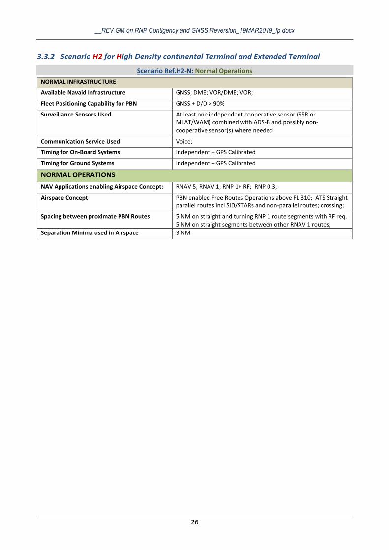
3.3.2 Scenario H2 for High Density continental Terminal and Extended Terminal
Scenario Ref.H2-N: Normal Operations
NORMAL INFRASTRUCTURE
Available Navaid Infrastructure GNSS; DME; VOR/DME; VOR;
Fleet Positioning Capability for PBN GNSS + D/D > 90%
Surveillance Sensors Used At least one independent cooperative sensor (SSR or MLAT/WAM) combined with ADS-B and possibly non-cooperative sensor(s) where needed
Communication Service Used Voice;
Timing for On-Board Systems Independent + GPS Calibrated
Timing for Ground Systems Independent + GPS Calibrated
NORMAL OPERATIONS
NAV Applications enabling Airspace Concept: RNAV 5; RNAV 1; RNP 1+ RF; RNP 0.3;
Airspace Concept PBN enabled Free Routes Operations above FL 310; ATS Straight parallel routes incl SID/STARs and non-parallel routes; crossing;
Spacing between proximate PBN Routes 5 NM on straight and turning RNP 1 route segments with RF req. 5 NM on straight segments between other RNAV 1 routes;
Separation Minima used in Airspace 3 NM
__REV GM on RNP Contigency and GNSS Reversion_19MAR2019_fp.docx
27
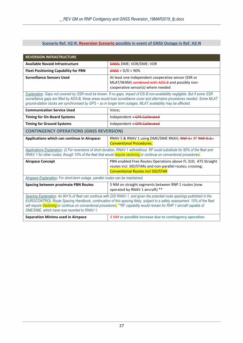
Scenario Ref. H2-R: Reversion Scenario possible in event of GNSS Outage in Ref. H2-N
REVERSION INFRASTRUCTURE
Available Navaid Infrastructure GNSS; DME; VOR/DME; VOR
Fleet Positioning Capability for PBN GNSS + D/D > 90%
Surveillance Sensors Used At least one independent cooperative sensor (SSR or MLAT/WAM) combined with ADS-B and possibly non-cooperative sensor(s) where needed
Explanation: Gaps not covered by SSR must be known. If no gaps, impact of DS-B non-availability negligible. But if some SSR surveillance gaps are filled by ADS-B, these areas would lose surveillance cover and alternative procedures needed. Some MLAT ground-station clocks are synchronised by GPS – so in longer term outages, MLAT availability may be affected.
Communication Service Used Voice;
Timing for On-Board Systems Independent + GPS Calibrated
Timing for Ground Systems Independent + GPS Calibrated
CONTINGENCY OPERATIONS (GNSS REVERSION)
Applications which can continue in Airspace: RNAV 5 & RNAV 1 using DME/DME RNAV; RNP 1+ RF RNP 0.3; Conventional Procedures.
Applications Explanation: (i) For reversions of short duration, RNAV 1 with/without RF could substitute for 90% of the fleet and RNAV 1 for other routes; though 10% of the fleet that would require vectoring or continue on conventional procedures.
Airspace Concept PBN enabled Free Routes Operations above FL 310; ATS Straight routes incl. SID/STARs and non-parallel routes; crossing; Conventional Routes incl SID/STAR
Airspace Explanation: For short-term outage, parallel routes can be maintained.
Spacing between proximate PBN Routes 5 NM on straight segments between RNP 1 routes (now operated by RNAV 1 aircraft) **
Spacing Explanation: As 90+% of fleet can continue with D/D RNAV 1, and given the potential route spacings published in the EUROCONTROL Route Spacing Handbook, continuation of this spacing likely, subject to a safety assessment. 10% of the fleet will require Vectoring or continue on conventional procedures. **RF capability would remain for RNP 1 aircraft capable of DME/DME, which have now reverted to RNAV 1.
Separation Minima used in Airspace 3 NM or possible increase due to contingency operation
__REV GM on RNP Contigency and GNSS Reversion_19MAR2019_fp.docx
28
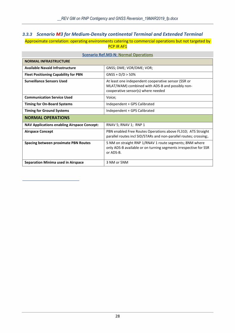
3.3.3 Scenario M3 for Medium-Density continental Terminal and Extended Terminal
Approximate correlation: operating environments catering to commercial operations but not targeted by PCP IR AF1
Scenario Ref.M3-N: Normal Operations
NORMAL INFRASTRUCTURE
Available Navaid Infrastructure GNSS; DME; VOR/DME; VOR;
Fleet Positioning Capability for PBN GNSS + D/D > 50%
Surveillance Sensors Used At least one independent cooperative sensor (SSR or MLAT/WAM) combined with ADS-B and possibly non-cooperative sensor(s) where needed
Communication Service Used Voice;
Timing for On-Board Systems Independent + GPS Calibrated
Timing for Ground Systems Independent + GPS Calibrated
NORMAL OPERATIONS
NAV Applications enabling Airspace Concept: RNAV 5; RNAV 1; RNP 1
Airspace Concept PBN enabled Free Routes Operations above FL310; ATS Straight parallel routes incl SID/STARs and non-parallel routes; crossing;.
Spacing between proximate PBN Routes 5 NM on straight RNP 1/RNAV 1 route segments; 8NM where only ADS-B available or on turning segments irrespective for SSR or ADS-B.
Separation Minima used in Airspace 3 NM or 5NM
__REV GM on RNP Contigency and GNSS Reversion_19MAR2019_fp.docx
29
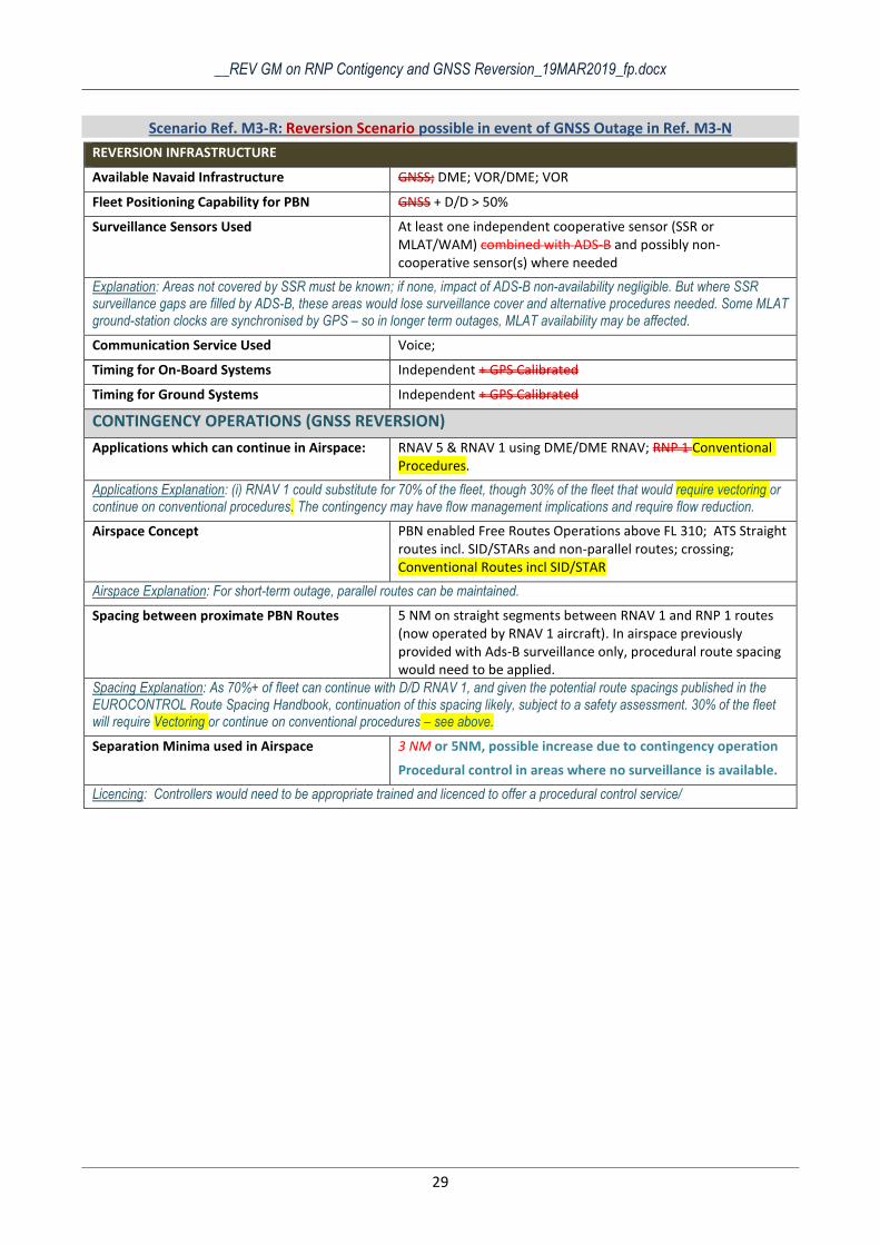
Scenario Ref. M3-R: Reversion Scenario possible in event of GNSS Outage in Ref. M3-N
REVERSION INFRASTRUCTURE
Available Navaid Infrastructure GNSS; DME; VOR/DME; VOR
Fleet Positioning Capability for PBN GNSS + D/D > 50%
Surveillance Sensors Used At least one independent cooperative sensor (SSR or MLAT/WAM) combined with ADS-B and possibly non-cooperative sensor(s) where needed
Explanation: Areas not covered by SSR must be known; if none, impact of ADS-B non-availability negligible. But where SSR surveillance gaps are filled by ADS-B, these areas would lose surveillance cover and alternative procedures needed. Some MLAT ground-station clocks are synchronised by GPS – so in longer term outages, MLAT availability may be affected.
Communication Service Used Voice;
Timing for On-Board Systems Independent + GPS Calibrated
Timing for Ground Systems Independent + GPS Calibrated
CONTINGENCY OPERATIONS (GNSS REVERSION)
Applications which can continue in Airspace: RNAV 5 & RNAV 1 using DME/DME RNAV; RNP 1 Conventional Procedures.
Applications Explanation: (i) RNAV 1 could substitute for 70% of the fleet, though 30% of the fleet that would require vectoring or continue on conventional procedures. The contingency may have flow management implications and require flow reduction.
Airspace Concept PBN enabled Free Routes Operations above FL 310; ATS Straight routes incl. SID/STARs and non-parallel routes; crossing; Conventional Routes incl SID/STAR
Airspace Explanation: For short-term outage, parallel routes can be maintained.
Spacing between proximate PBN Routes 5 NM on straight segments between RNAV 1 and RNP 1 routes (now operated by RNAV 1 aircraft). In airspace previously provided with Ads-B surveillance only, procedural route spacing would need to be applied.
Spacing Explanation: As 70%+ of fleet can continue with D/D RNAV 1, and given the potential route spacings published in the EUROCONTROL Route Spacing Handbook, continuation of this spacing likely, subject to a safety assessment. 30% of the fleet will require Vectoring or continue on conventional procedures – see above.
Separation Minima used in Airspace 3 NM or 5NM, possible increase due to contingency operation
Procedural control in areas where no surveillance is available.
Licencing: Controllers would need to be appropriate trained and licenced to offer a procedural control service/
__REV GM on RNP Contigency and GNSS Reversion_19MAR2019_fp.docx
30
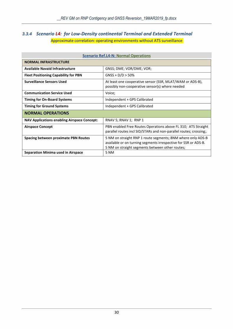
3.3.4 Scenario L4: for Low-Density continental Terminal and Extended Terminal
Approximate correlation: operating environments without ATS surveillance
Scenario Ref.L4-N: Normal Operations
NORMAL INFRASTRUCTURE
Available Navaid Infrastructure GNSS; DME; VOR/DME; VOR;
Fleet Positioning Capability for PBN GNSS + D/D > 50%
Surveillance Sensors Used At least one cooperative sensor (SSR, MLAT/WAM or ADS-B), possibly non-cooperative sensor(s) where needed
Communication Service Used Voice;
Timing for On-Board Systems Independent + GPS Calibrated
Timing for Ground Systems Independent + GPS Calibrated
NORMAL OPERATIONS
NAV Applications enabling Airspace Concept: RNAV 5; RNAV 1; RNP 1
Airspace Concept PBN enabled Free Routes Operations above FL 310; ATS Straight parallel routes incl SID/STARs and non-parallel routes; crossing;.
Spacing between proximate PBN Routes 5 NM on straight RNP 1 route segments; 8NM where only ADS-B available or on turning segments irrespective for SSR or ADS-B. 5 NM on straight segments between other routes;
Separation Minima used in Airspace 5 NM
__REV GM on RNP Contigency and GNSS Reversion_19MAR2019_fp.docx
31
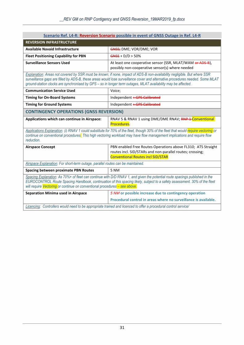
Scenario Ref. L4-R: Reversion Scenario possible in event of GNSS Outage in Ref. L4-R
REVERSION INFRASTRUCTURE
Available Navaid Infrastructure GNSS; DME; VOR/DME; VOR
Fleet Positioning Capability for PBN GNSS + D/D > 50%
Surveillance Sensors Used At least one cooperative sensor (SSR, MLAT/WAM or ADS-B), possibly non-cooperative sensor(s) where needed
Explanation: Areas not covered by SSR must be known; if none, impact of ADS-B non-availability negligible. But where SSR surveillance gaps are filled by ADS-B, these areas would lose surveillance cover and alternative procedures needed. Some MLAT ground-station clocks are synchronised by GPS – so in longer term outages, MLAT availability may be affected.
Communication Service Used Voice;
Timing for On-Board Systems Independent + GPS Calibrated
Timing for Ground Systems Independent + GPS Calibrated
CONTINGENCY OPERATIONS (GNSS REVERSION)
Applications which can continue in Airspace: RNAV 5 & RNAV 1 using DME/DME RNAV; RNP 1 Conventional Procedures.
Applications Explanation: (i) RNAV 1 could substitute for 70% of the fleet, though 30% of the fleet that would require vectoring or continue on conventional procedures. This high vectoring workload may have flow management implications and require flow reduction.
Airspace Concept PBN enabled Free Routes Operations above FL310; ATS Straight routes incl. SID/STARs and non-parallel routes; crossing; Conventional Routes incl SID/STAR
Airspace Explanation: For short-term outage, parallel routes can be maintained.
Spacing between proximate PBN Routes 5 NM
Spacing Explanation: As 70%+ of fleet can continue with D/D RNAV 1, and given the potential route spacings published in the EUROCONTROL Route Spacing Handbook, continuation of this spacing likely, subject to a safety assessment. 30% of the fleet will require Vectoring or continue on conventional procedures – see above.
Separation Minima used in Airspace 5 NM or possible increase due to contingency operation
Procedural control in areas where no surveillance is available.
Licencing: Controllers would need to be appropriate trained and licenced to offer a procedural control service/

__REV GM on RNP Contigency and GNSS Reversion_19MAR2019_fp.docx
32
__REV GM on RNP Contigency and GNSS Reversion_19MAR2019_fp.docx
33
4. PROCESS FOR CONTINGENCY SCENARIO DEVELOPMENT
Cross Reference: European Airspace Concept Handbook, Activities 1-17.
Cross Reference: European Navaid Infrastructure Planning Handbook, Activities IA-1 to IA-8.
When developing an Airspace Concept, Activity 6 of the European Airspace Concept Handbook makes it clear that the Enablers available to support the airspace design must be identified, as must the constraints to be mitigated, and what assumptions have to be made. What is equally clear, is that when undertaking the Airspace Design, Activity 7, the design schema must cater for normal and contingency operations with contingency procedures to match. The Airspace Concept is a total package, and having an ideal operating scenario is not enough. Non-Normal operations must be envisaged and accounted for, therefore Airspace Concept developers should plan Contingency operations as part of the Airspace Concept.
When developing a CNS evolution plan, the Infrastructure Manager has two primary considerations: the first is servicing the ATM requirements of its ANSP, the second is meeting the cost-saving or regulatory targets for Navaid rationalisation/decommissioning. The Infrastructure manager is thus often faced with counter pressures, which need to be managed.
In as much as the Airspace Concept developers must communicate their airspace evolution plans to the Infrastructure Managers, it is equally important that Airspace Designers and Planners are aware of the strategic evolution of the Navaid Infrastructure. Changes in the Navigation infrastructure may require changes in the operations or airspace design for reasons not connected to ATM requirements e.g. decision not to replace particular VORs at the end of their life cycle could cause conventional STAR/SIDs to be withdrawn or at best, altered. It is quite conceivable that uncoordinated rationalisation decisions could force airspace changes with unintended consequences.
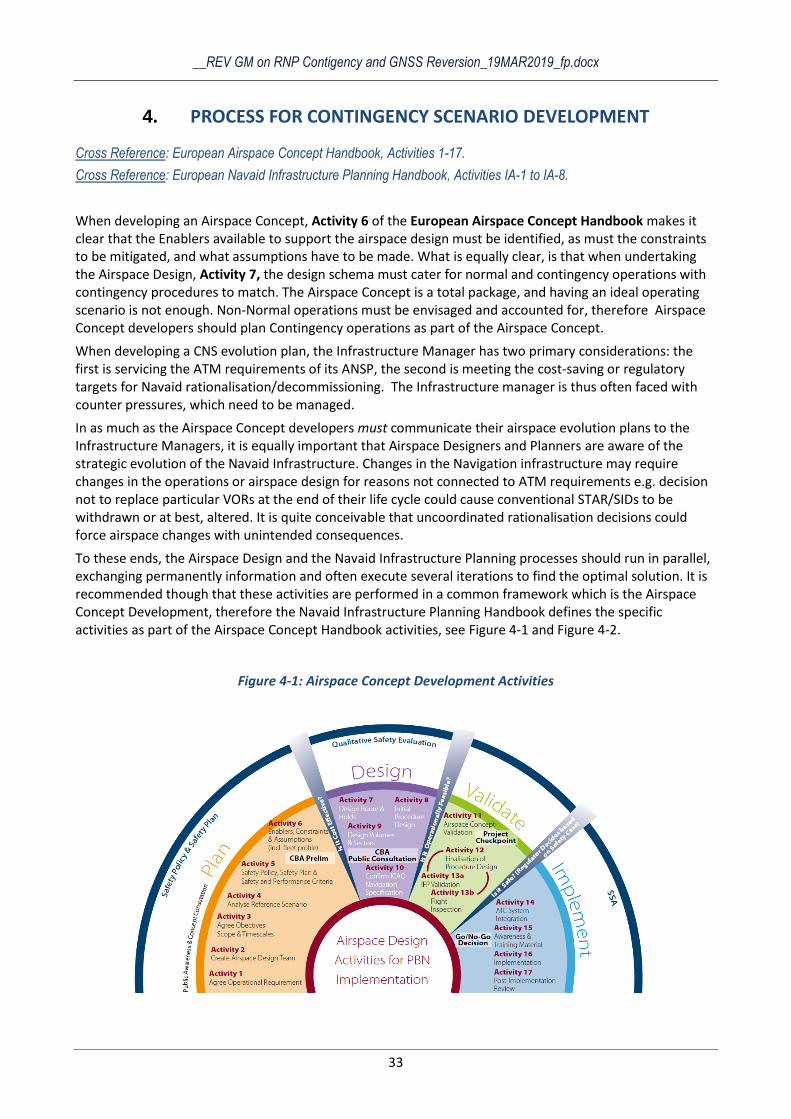
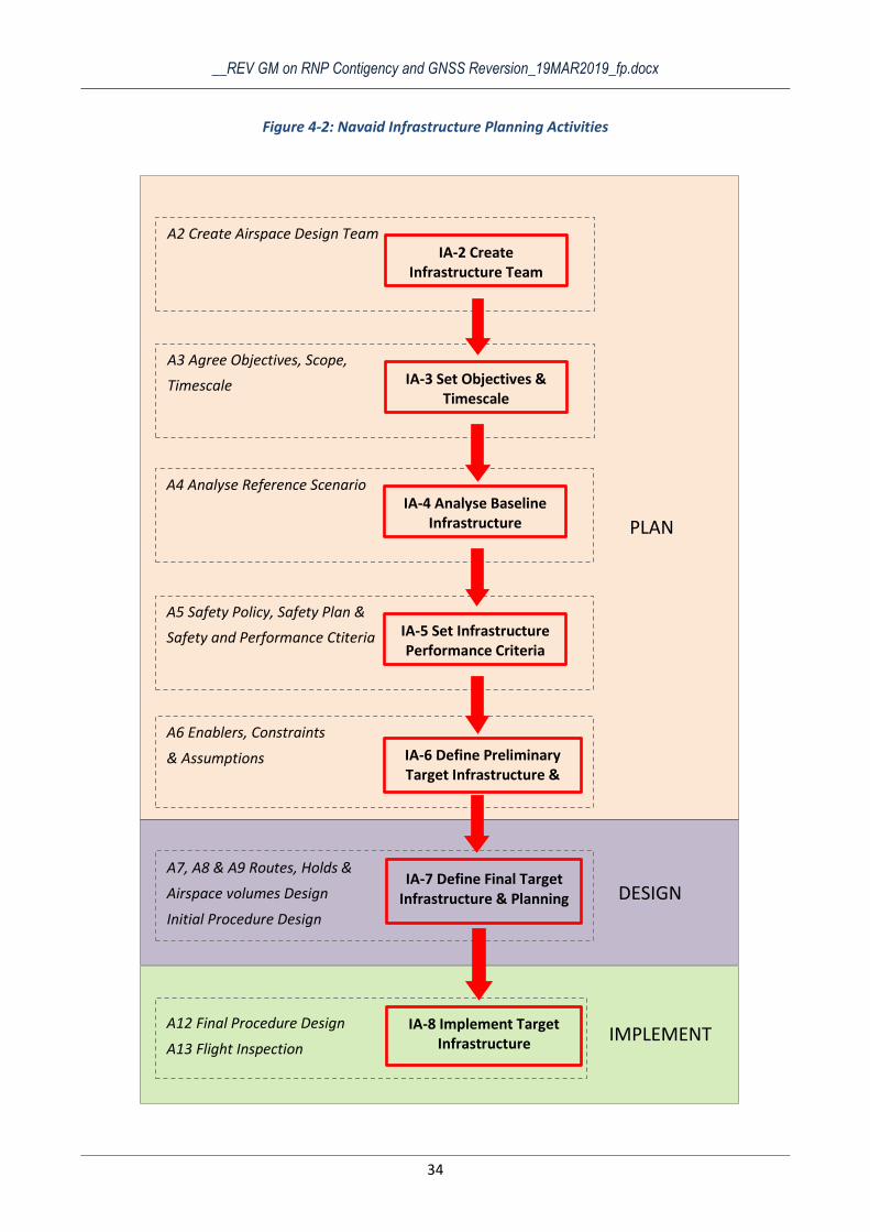
To these ends, the Airspace Design and the Navaid Infrastructure Planning processes should run in parallel, exchanging permanently information and often execute several iterations to find the optimal solution. It is recommended though that these activities are performed in a common framework which is the Airspace Concept Development, therefore the Navaid Infrastructure Planning Handbook defines the specific activities as part of the Airspace Concept Handbook activities, see Figure 4-1 and Figure 4-2.
Figure 4-1: Airspace Concept Development Activities
__REV GM on RNP Contigency and GNSS Reversion_19MAR2019_fp.docx
34
Figure 4-2: Navaid Infrastructure Planning Activities
A12 Final Procedure Design
A13 Flight Inspection
A6 Enablers, Constraints
& Assumptions
A5 Safety Policy, Safety Plan &
Safety and Performance Ctiteria IA-5 Set Infrastructure Performance Criteria
PLAN
A2 Create Airspace Design Team IA-2 Create
Infrastructure Team
A7, A8 & A9 Routes, Holds &
Airspace volumes Design
Initial Procedure Design
IA-6 Define Preliminary Target Infrastructure &
Planning
IA-7 Define Final Target Infrastructure & Planning DESIGN
IA-8 Implement Target Infrastructure
A3 Agree Objectives, Scope,
Timescale
IMPLEMENT
A4 Analyse Reference Scenario IA-4 Analyse Baseline
Infrastructure
IA-3 Set Objectives & Timescale
__REV GM on RNP Contigency and GNSS Reversion_19MAR2019_fp.docx
35
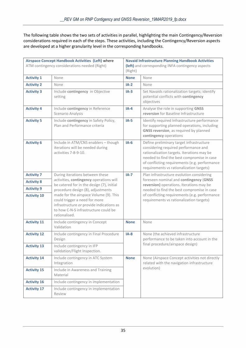
The following table shows the two sets of activities in parallel, highlighting the main Contingency/Reversion considerations required in each of the steps. These activities, including the Contingency/Reversion aspects are developed at a higher granularity level in the corresponding handbooks.
Airspace Concept Handbook Activities (Left) where ATM contingency considerations needed (Right)
Navaid Infrastructure Planning Handbook Activities (left) and corresponding INFA contingency aspects (Right)
Activity 1 None None None
Activity 2 None IA-2 None
Activity 3 Include contingency in Objective setting
IA-3 Set Navaids rationalization targets; identify potential conflicts with contingency objectives
Activity 4 Include contingency in Reference Scenario Analysis
IA-4 Analyse the role in supporting GNSS reversion for Baseline Infrastructure
Activity 5 Include contingency in Safety Policy, Plan and Performance criteria
IA-5 Identify required Infrastructure performance for supporting planned operations, including GNSS reversion, as required by planned contingency operations
Activity 6 Include in ATM/CNS enablers – though iterations will be needed during activities 7-8-9-10.
IA-6 Define preliminary target infrastructure considering required performance and rationalization targets. Iterations may be needed to find the best compromise in case of conflicting requirements (e.g. performance requirements vs rationalization targets)
Activity 7 During iterations between these activities, contingency operations will be catered for in the design (7), initial procedure design (8), adjustments made for the airspace Volume (9). This could trigger a need for more infrastructure or provide indications as to how C-N-S infrastructure could be rationalised.
IA-7 Plan infrastructure evolution considering foreseen nominal and contingency (GNSS reversion) operations. Iterations may be needed to find the best compromise in case of conflicting requirements (e.g. performance requirements vs rationalization targets)
Activity 8
Activity 9
Activity 10
Activity 11 Include contingency in Concept Validation
None None
Activity 12 Include contingency in Final Procedure Design
IA-8 None (the achieved infrastructure performance to be taken into account in the final procedure/airspace design) Activity 13 Include contingency in IFP
validation/Flight Inspection.
Activity 14 Include contingency in ATC System Integration
None None (Airspace Concept activities not directly related with the navigation infrastructure evolution) Activity 15 Include in Awareness and Training
Material
Activity 16 Include contingency in implementation
Activity 17 Include contingency in implementation Review
__REV GM on RNP Contigency and GNSS Reversion_19MAR2019_fp.docx
36
4.1 DEVELOPMENT OF A VOR(/DME) MON
In section 3 several normal operations/reversion scenarios have been presented corresponding to different operating environments. All these scenarios highlight the main future role of the ground Navaids in supporting the navigation reversion for contingency operations in case of the unavailability of GNSS, which will become the primary navigation enabler for normal operations. These scenarios also indicate that DME/DME is expected to enable RNAV 1 (RNP 1 reversion) operations in case of area wide GPS outages. Although the availability of VOR Navaids is assumed in all normal/reversion cases, the description does not elaborate on the foreseen use of this type of Navaid. Furthermore, the first part of section 4 gives an overview on the Airspace Concept Development activities and the Infrastructure planning activities, highlighting the importance of the coordination and exchange of information but without offering details on these processes. While guidance materials on the design and planning of the DME network already exist or are being developed ( References), a dedicated document covering the VOR(/DME) MON planning is not foreseen. This topic is covered to some extent in the Navaid Infrastructure Planning Handbook, however not at the same level of detail provided by the DME guidance. Since the future operational role of the VOR MON is less straightforward than the role of the DME network, it is worth developing further on this topic in the present document. Therefore the following paragraphs present an example of interaction between the Airspace Concept Development and Infrastructure Planning, focused on planning the VOR MON evolution. With this objective set, the first step will be to give an overview of the foreseen residual operational roles of VOR.
4.1.1 Residual operational roles of VOR
Cross Reference: European Navaid Infrastructure Planning Handbook
ICAO Annex 10 provides in Attachment H a “Strategy For Rationalization of Conventional Radio Navigation Aids And Evolution Toward Supporting Performance-Based Navigation”. This strategy includes operational considerations regarding the future use of radio navigation facilities. In whatAs regards the VOR, this ICAO document identifies the following residual operational purposes:
a) as a reversionary navigation capability (for example, for general aviation operations in order to assist
in avoiding airspace infringements);
b) to provide navigation, cross-checking and situational awareness, especially for terminal area
operations (pilot MSA awareness, avoiding premature automatic flight control system arming for ILS
intercept, aircraft operational contingency procedures, such as engine failure on take-off, missed
approaches, if required by local safety cases), in particular in areas where low altitude DME/DME
coverage is limited; c) for VOR/DME inertial updating where DME/DME updating is not available;
d) for non-precision approaches, as long as users are not equipped for RNP approaches and if no other
suitable means of precision approach is available;
e) for conventional SID/STAR to serve non-PBN-capable aircraft;
f) as required to support the operations of State aircraft; and
g) to support procedural separation (as detailed in Doc 4444).
The same attachment contains the following recommendation:
3.3.3 In order to provide DME-based RNAV capabilities, those locations which are retained for VOR should normally also be equipped with a co-located DME.
Therefore, the present guidance material recommends as well that priority is given to the retention of VOR/DME facilities (as opposed to VOR standalone) and therefore in general the VOR(/DME) MON terminology is used instead of VOR MON.
__REV GM on RNP Contigency and GNSS Reversion_19MAR2019_fp.docx
37
4.1.2 VOR(/DME) MON Design Process
As anticipated in 4.1.1, this section gives a practical example on the application of the specific Airspace Concept Design activities and the Infrastructure Planning activities for the rationalization of the VOR infrastructure and the design and planning of the VOR(/DME) MON. The example aims at highlighting the required cooperation between ATM and Infrastructure Managers in this process and the information to be exchanged between these actors. The process is presented from an Infrastructure Planning perspective, being an overview of the information presented in the Navaids Infrastructure Handbook.
From the residual operational purposes of VOR listed in 4.1.1 it is noted that this type of navaid may still be used in all phases of flight (although in accordance with the foreseen PBN implementation the overall role shifts gradually toward supporting reversionary operations). Therefore the process has to cover all phases of flight, starting from the requirements definition to the design, planning and implementation.
4.1.2.1 Objectives and Timescales (IA-3)
This initial phase of the project needs to identify and consider all constraints applicable directly to the evolution infrastructure, independent of the requirements stemming from the targeted Airspace Concept. These constraints could be:
- Internal, e.g. cost saving objectives (including staff cuttings), optimization of maintenance activities
(avoid difficult sites), systems life cycle (avoid replacement) - External, e.g. regulations on infrastructure rationalization
These requirements which are independent from the ATM needs are not supposed to override the ATM requirements. Uncoordinated decommissioning of navaids may lead to a negative impact on airspace capacity and even on the safety of the operations, which would cancel the short term benefits that may be generated by the infrastructure rationalization. However these requirements need to be considered in combination with the ATM requirements in order to find an optimal and coordinated solution in planning the airspace and infrastructure changes
4.1.2.2 Analyse Baseline Infrastructure (IA-4)
This step is intended to give a full picture of the existing navigation infrastructure (in this particular case existing VOR network) and the operational role of each facility. The outputs expected:
- Full inventory of the existing VORs, the operating parameters, technical status, specific site issues,
maintenance personnel issues, etc.
- Operational roles, routes and procedures supported by each VOR The full picture of the operations supported by each VOR is paramount in understanding the impact of decommissioning the navaid and the airspace changes that may need to be implemented beforehand.
4.1.2.3 Set Infrastructure Performance Criteria (IA-5)
As depicted in Figure 4-2 this activity should be part of and driven by Activity 5 of the Airspace Concept Development. Activity 5 is expected to set the overall safety and performance criteria. This activity is focused on the safety and the performance of the airspace operations, and should consider both normal and contingency scenarios. Therefore the agreed objectives and criteria may have implications also on the required infrastructure. For instance one outcome of this phase of the project could be that the total loss of navigation capability in a certain airspace represents a hazard with high impact on safety, therefore reversion means must be provided, at least for a minimum percentage of aircraft. At this stage the required continuity and availability of the reversionary navigation service (in this specific case the VOR(/DME) service) could also be defined. Although this activity is normally led by the Safety and the ATM experts, the navigation infrastructure experts should at least observe the progress to be aware of the safety and performance criteria considered, understand the impact on the infrastructure and eventually contribute to the derivation of safety and performance criteria specific to the required navigation services.
__REV GM on RNP Contigency and GNSS Reversion_19MAR2019_fp.docx
38
4.1.2.4 Define Preliminary Target Infrastructure & Planning (IA-6)
IA-6 is the final activity of the planning phase and should be closely coordinated with Activity 6 of the Airspace Concept Development. In this stage of the project, the airspace designers have to define the ATM/CNS assumptions on which the future Airspace Concept relies. The Navigation specific assumptions must be defined for:
- All phases of flight - Normal and contingency operations.
Specifically for the VOR(/DME) MON, having in mind the current and residual operational roles, and considering the analysis and the assumptions on the evolution of the fleet equipage, the following minimum set of considerations is recommended:
- En route & TMA Is VOR/DME coverage required to support navigation in FRA (RNAV 5) and with what
redundancy Is VOR/DME coverage required to support navigation on conventional ATS routes Is VOR/DME coverage required to support navigation on RNAV 5 ATS routes (e.g.
where DME/DME coverage not available) Airspaces where VORs are still needed to provide navigation, cross-checking and
situational awareness Airspaces where VORs are still required to support the operations of State aircraft or
procedural separation
Controlled/Uncontrolled airspace where VORs are still needed in order to assist in
avoiding airspace infringements - Approach and landing
Aerodromes where conventional IAP are still needed. The analysis should consider
the aerodromes which are designated as alternates for major aerodromes and for
aerodromes where only RNP APCH procedures are foreseen Aerodromes where VOR(/DME) is needed to support missed approach operations
Aerodromes where VOR(/DME) IAP to be withdrawn VOR(/DME) IAP to be maintained (potentially redesigned)
Once more we highlight here the importance of this this analysis both for normal and contingency operations. In a nutshell, the main outputs expected from this analysis by the infrastructure planners (inputs to IA-6) are: where VOR(/DME) coverage is needed and with what redundancy. At a higher granularity level, the analysis should the following information relative to the operational purpose of the VOR(/DME) MON:
Airspace volumes (estimated horizontal and vertical dimensions)
Existing and planned routes and altitude limitations
Conventional SIDs/STARs to be withdrawn
Conventional SIDs/STARs to be maintained (potentially redesigned)
IAP to be withdrawn
IAP to be maintained (potentially redesigned)
Missed approach procedures to be withdrawn
Missed approach procedures maintained (potentially redesigned)
When planning the evolution of the VOR(/DME) MON, the infrastructure planners should consider the two set of requirements:
__REV GM on RNP Contigency and GNSS Reversion_19MAR2019_fp.docx
39
- ATM requirements identified in Activity 6
- Infrastructure Constraints identified in IA-3 This activity will also take into account the findings of the baseline infrastructure analysis (IA-4).
Starting from these inputs a preliminary configuration of the VOR(/DME) MON can be defined together with the implementation timelines. As stated before, the two sets of requirements can often be contradictory, in which case several iterations may be needed between Activity 6 / IA-6 before arriving to an acceptable compromise. In any case in this stage the overall target infrastructure configuration is still a preliminary one, which may need be refined taking into account the concrete airspace/procedure design defined in Activities 7, 8 & 9. Often, in the engineering design context IA-6 corresponds to a Feasibility Study.
4.1.2.5 Define Final Target Infrastructure & Planning (IA-7)
The objective of this phase of the project (actual design phase) is to define the final configuration of the target infrastructure and plan the implementation. In what regards the VOR(/DME) MON, since the introduction of new facilities is not expected, in this activity the preliminary configuration should not change significantly (unless in the airspace concept design phase there are major changes in what regards the initial assumptions on navigation enablers). However, due to specific airspace/procedure design the set of facilities to be maintained could change slightly.
The second major output of this activity is the decommissioning/replacement planning. This planning should be closely coordinated with the airspace changes planning such that
- VOR facilities are not decommissioned before all required airspace changes are implemented - The continuity and availability of the navigation service is not impacted due to unreliability of old
systems (late replacement of retained facilities)
4.1.2.6 Implement Target Infrastructure (IA-8)
The implementation phase consist mainly in the execution of the changes planned in IA-7. Again, since the relocation or the installation of new VOR facilities is highly unlikely, the actual coverage and performance of all ground stations is known a priory. Therefore, these parameters can be taken into account in the airspace/procedure design without the potential need for design refinement based on achieved performance (such as may be the case for new or relocated DME facilities).
However, it is important to highlight again the importance of a coordinated implementation of the airspace and infrastructure changes. Any delays in the implementation of the new airspace concept (which may require that the decommissioning of VORs is postponed) should be communicated as early as possible to the infrastructure planners. On the other hand, the VOR facilities should not be withdrawn from operation (even if in accordance with the planning) without the final agreement of ATM.

__REV GM on RNP Contigency and GNSS Reversion_19MAR2019_fp.docx
40

__REV GM on RNP Contigency and GNSS Reversion_19MAR2019_fp.docx
41
5. CONCLUSION
The development of a future Airspace Concept includes the simultaneous development of contingency procedures for certain outages, one of which is GNSS loss.
When developed alongside the Airspace Concept, Contingency Scenarios inter-dependencies should be identified so that, if needs be, double or even triple contingencies are catered for.
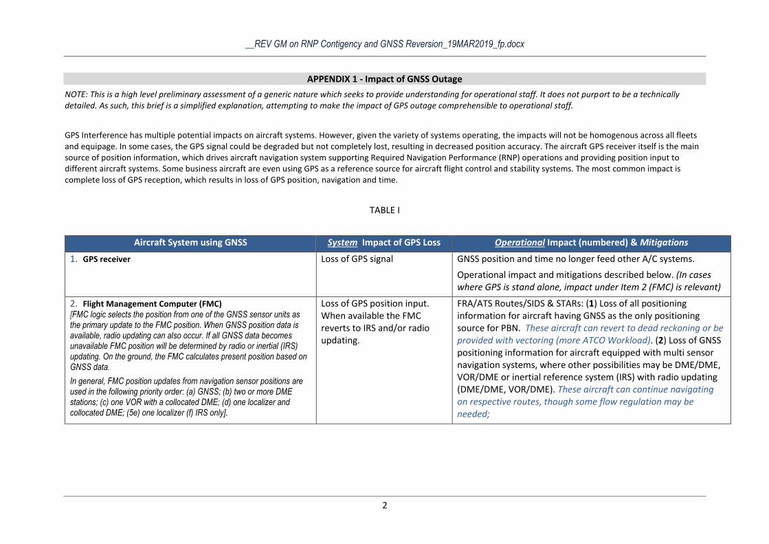
__REV GM on RNP Contigency and GNSS Reversion_19MAR2019_fp.docx
2
APPENDIX 1 - Impact of GNSS Outage
NOTE: This is a high level preliminary assessment of a generic nature which seeks to provide understanding for operational staff. It does not purport to be a technically detailed. As such, this brief is a simplified explanation, attempting to make the impact of GPS outage comprehensible to operational staff.
GPS Interference has multiple potential impacts on aircraft systems. However, given the variety of systems operating, the impacts will not be homogenous across all fleets and equipage. In some cases, the GPS signal could be degraded but not completely lost, resulting in decreased position accuracy. The aircraft GPS receiver itself is the main source of position information, which drives aircraft navigation system supporting Required Navigation Performance (RNP) operations and providing position input to different aircraft systems. Some business aircraft are even using GPS as a reference source for aircraft flight control and stability systems. The most common impact is complete loss of GPS reception, which results in loss of GPS position, navigation and time.
TABLE I
Aircraft System using GNSS System Impact of GPS Loss Operational Impact (numbered) & Mitigations
1. GPS receiver
Loss of GPS signal GNSS position and time no longer feed other A/C systems.
Operational impact and mitigations described below. (In cases where GPS is stand alone, impact under Item 2 (FMC) is relevant)
2. Flight Management Computer (FMC) [FMC logic selects the position from one of the GNSS sensor units as the primary update to the FMC position. When GNSS position data is available, radio updating can also occur. If all GNSS data becomes unavailable FMC position will be determined by radio or inertial (IRS) updating. On the ground, the FMC calculates present position based on GNSS data.
In general, FMC position updates from navigation sensor positions are used in the following priority order: (a) GNSS; (b) two or more DME stations; (c) one VOR with a collocated DME; (d) one localizer and collocated DME; (5e) one localizer (f) IRS only].
Loss of GPS position input. When available the FMC reverts to IRS and/or radio updating.
FRA/ATS Routes/SIDS & STARs: (1) Loss of all positioning information for aircraft having GNSS as the only positioning source for PBN. These aircraft can revert to dead reckoning or be provided with vectoring (more ATCO Workload). (2) Loss of GNSS positioning information for aircraft equipped with multi sensor navigation systems, where other possibilities may be DME/DME, VOR/DME or inertial reference system (IRS) with radio updating (DME/DME, VOR/DME). These aircraft can continue navigating on respective routes, though some flow regulation may be needed;

__REV GM on RNP Contigency and GNSS Reversion_19MAR2019_fp.docx
3
3. Ground Based Augmentation System (GBAS) [GBAS is a ground-based augmentation system used for precision landing. It is a GPS-dependent alternative to ILS, which uses a single GBAS airport ground station to transmit corrected GNSS data to suitably equipped aircraft to enable them to fly a precision approach with much greater flexibility.]
Loss of GBAS position. (GBAS ground system, can no longer ‘augment’ the GPS signal).
(3) GBAS approaches not possible; may generate missed approaches and increased workload. Alternative instrument approach procedure, such as ILS, needed. If not available, diversion may be required.
4. Satellite Based Augmentation System (SBAS) [SBAS supports wide-area or regional augmentation with additional satellite-broadcast messages. Such systems are commonly composed of multiple ground stations and take measurements of one or more of the GPS satellites].
Loss of SBAS position. (The SBAS system can no longer ‘augment’ the GPS signal.
(4) RNP Approaches (Baro or LPV) not possible; may generate missed approaches and increased workload. Alternative instrument approach procedure, such as ILS, needed. If not available, diversion may be required.
5. Synthetic vision system (SVS) [SVS provides situational awareness by using terrain, obstacle and other databases. A typical SVS application uses a set of databases stored on board the aircraft, an image generator computer, and a display. Navigation solution obtained using GNSS and inertial reference systems. SVS can enable lower minima on different kinds of approach].
Loss of GNSS position. Loss of synthetic vision display and flight path marker on PFD. GNSS outage might affect capability to apply operational credit
(5) SVS becomes unusable. Alternative instrument approach procedure not SVS dependent, needed e.g. ILS. If not available, diversion may be required.
6. ATC Transponder – Mode S / SSR function No impact on independent surveillance positioning function.
Some downlinked airborne parameters (e.g. possibly groundspeed, track angle, track angle rate) may be lost or degraded.
Operational impact see Table II.

__REV GM on RNP Contigency and GNSS Reversion_19MAR2019_fp.docx
4
7. ATC Transponder – ADS–B function [An ADS-B equipped aircraft determines its own position (longitude, latitude, altitude, and time) using GNSS and periodically broadcasts this position and other relevant flight information to ground stations and other aircraft with ADS-B equipment via Mode S ES messages. In the new space based ADS-B applications the ADS-B reports are sent via a satellite link.
The information can be used by ATC as a complement or replacement for secondary surveillance radar or multilateration,. It can also be received by other aircraft to provide situational awareness.]
Loss of (qualified) position and groundspeed in ADS-B Out data.
Operational impact see Table II.
8. ADS-B In system Loss of ADS-B In application Safety and capacity reduction.
Loss of ADS-B IN functionality for impacted aircraft. If own aircraft is impacted by the outage the ADS-B IN function it is lost for all tracked aircraft. If traffic is impacted by the outage the ADS-B IN function it is lost for impacted traffic.
9. ACAS Loss of ADS-B input to ACAS RF reducing function.
Loss of RF reducing functions in ACAS systems (the ACAS function itself is not impacted). If own aircraft is impacted by the outage the RF reducing function it is lost for all tracked aircraft. If traffic is impacted by the outage the RF reducing function it is lost for impacted traffic.
10. ADS-C ADS-C is intended to provide long distance position tracking, (and weather reporting...) as in transoceanic flight. In this case the messages are sent to a specific ATC center, via a satellite link.
Loss of position in ADS-C data.
See Table II
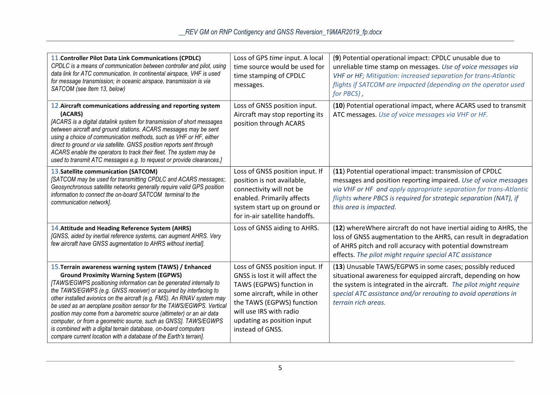
__REV GM on RNP Contigency and GNSS Reversion_19MAR2019_fp.docx
5
11. Controller Pilot Data Link Communications (CPDLC) CPDLC is a means of communication between controller and pilot, using data link for ATC communication. In continental airspace, VHF is used for message transmission; in oceanic airspace, transmission is via SATCOM (see Item 13, below)
Loss of GPS time input. A local time source would be used for time stamping of CPDLC messages.
(9) Potential operational impact: CPDLC unusable due to unreliable time stamp on messages. Use of voice messages via VHF or HF; Mitigation: increased separation for trans-Atlantic flights if SATCOM are impacted (depending on the operator used for PBCS) ,
12. Aircraft communications addressing and reporting system (ACARS)
[ACARS is a digital datalink system for transmission of short messages between aircraft and ground stations. ACARS messages may be sent using a choice of communication methods, such as VHF or HF, either direct to ground or via satellite. GNSS position reports sent through ACARS enable the operators to track their fleet. The system may be used to transmit ATC messages e.g. to request or provide clearances.]
Loss of GNSS position input. Aircraft may stop reporting its position through ACARS
(10) Potential operational impact, where ACARS used to transmit ATC messages. Use of voice messages via VHF or HF.
13. Satellite communication (SATCOM) [SATCOM may be used for transmitting CPDLC and ACARS messages;. Geosynchronous satellite networks generally require valid GPS position information to connect the on-board SATCOM terminal to the communication network].
Loss of GNSS position input. If position is not available, connectivity will not be enabled. Primarily affects system start up on ground or for in-air satellite handoffs.
(11) Potential operational impact: transmission of CPDLC messages and position reporting impaired. Use of voice messages via VHF or HF and apply appropriate separation for trans-Atlantic flights where PBCS is required for strategic separation (NAT), if this area is impacted.
14. Attitude and Heading Reference System (AHRS) [GNSS, aided by inertial reference systems, can augment AHRS. Very few aircraft have GNSS augmentation to AHRS without inertial].
Loss of GNSS aiding to AHRS. (12) whereWhere aircraft do not have inertial aiding to AHRS, the loss of GNSS augmentation to the AHRS, can result in degradation of AHRS pitch and roll accuracy with potential downstream effects. The pilot might require special ATC assistance
15. Terrain awareness warning system (TAWS) / Enhanced Ground Proximity Warning System (EGPWS)
[TAWS/EGWPS positioning information can be generated internally to the TAWS/EGWPS (e.g. GNSS receiver) or acquired by interfacing to other installed avionics on the aircraft (e.g. FMS). An RNAV system may be used as an aeroplane position sensor for the TAWS/EGWPS. Vertical position may come from a barometric source (altimeter) or an air data computer, or from a geometric source, such as GNSS]. TAWS/EGWPS is combined with a digital terrain database, on-board computers compare current location with a database of the Earth's terrain].
Loss of GNSS position input. If GNSS is lost it will affect the TAWS (EGPWS) function in some aircraft, while in other the TAWS (EGPWS) function will use IRS with radio updating as position input instead of GNSS.
(13) Unusable TAWS/EGPWS in some cases; possibly reduced situational awareness for equipped aircraft, depending on how the system is integrated in the aircraft. The pilot might require special ATC assistance and/or rerouting to avoid operations in terrain rich areas.
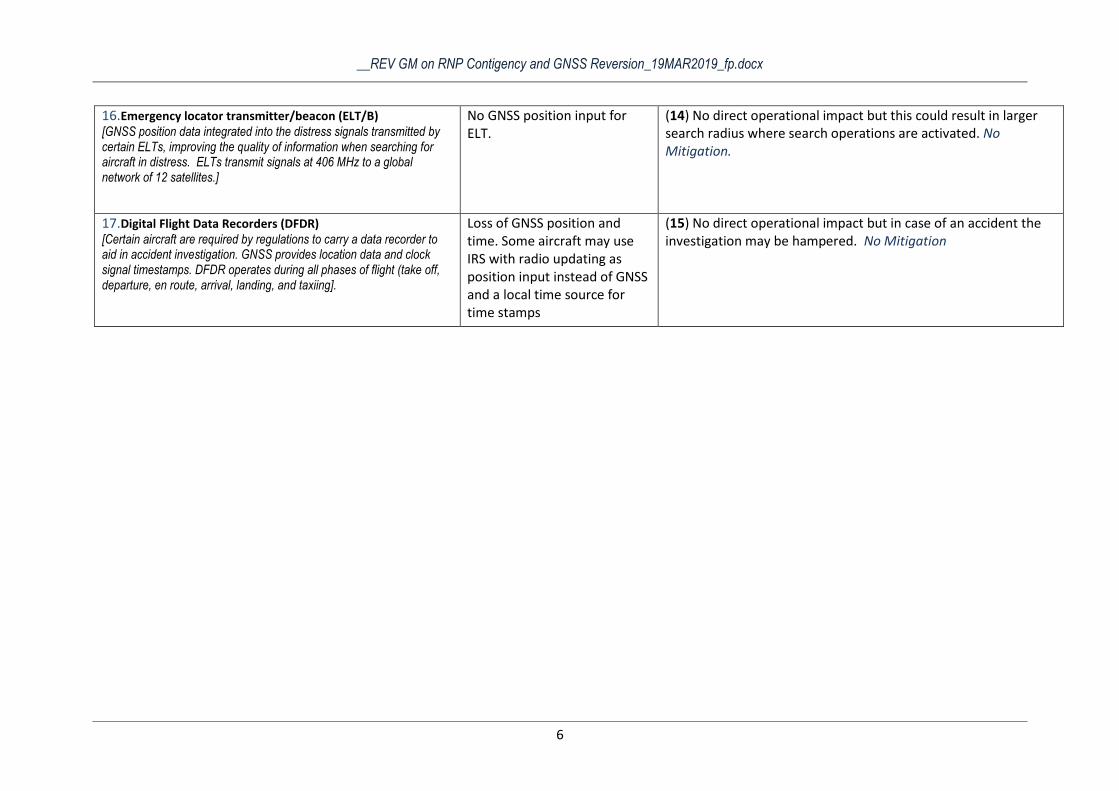
__REV GM on RNP Contigency and GNSS Reversion_19MAR2019_fp.docx
6
16. Emergency locator transmitter/beacon (ELT/B) [GNSS position data integrated into the distress signals transmitted by certain ELTs, improving the quality of information when searching for aircraft in distress. ELTs transmit signals at 406 MHz to a global network of 12 satellites.]
No GNSS position input for ELT.
(14) No direct operational impact but this could result in larger search radius where search operations are activated. No Mitigation.
17. Digital Flight Data Recorders (DFDR) [Certain aircraft are required by regulations to carry a data recorder to aid in accident investigation. GNSS provides location data and clock signal timestamps. DFDR operates during all phases of flight (take off, departure, en route, arrival, landing, and taxiing].
Loss of GNSS position and time. Some aircraft may use IRS with radio updating as position input instead of GNSS and a local time source for time stamps
(15) No direct operational impact but in case of an accident the investigation may be hampered. No Mitigation
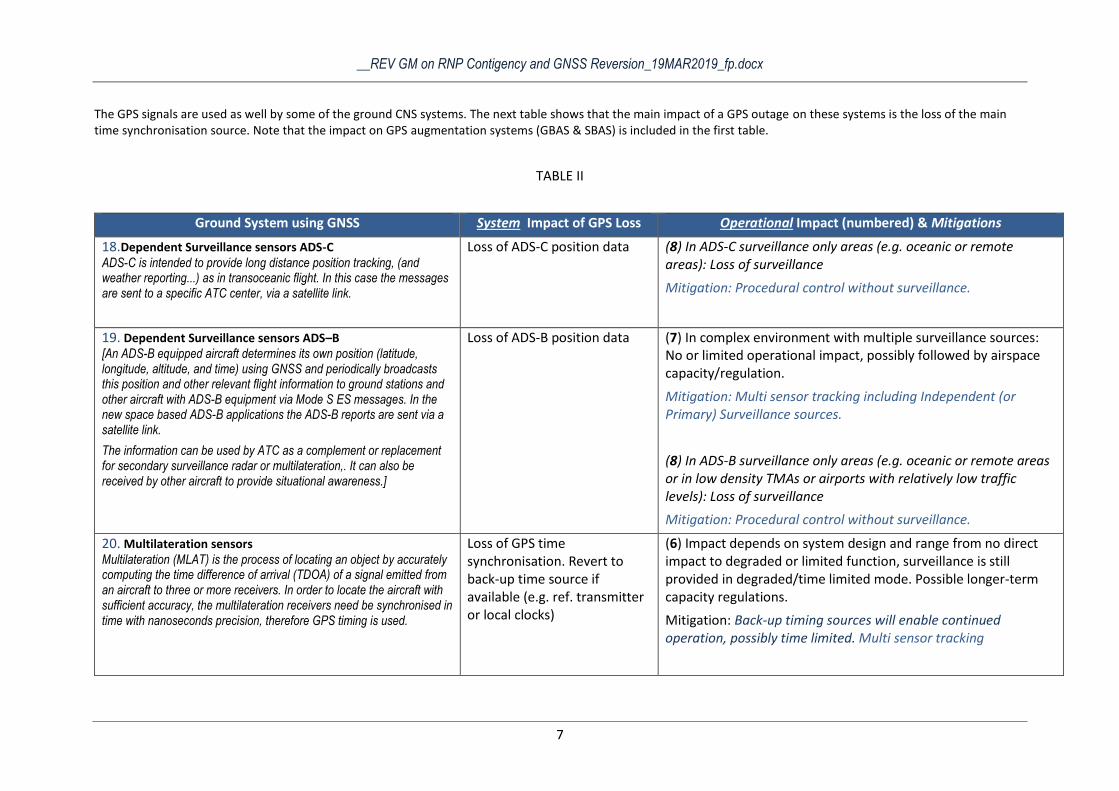
__REV GM on RNP Contigency and GNSS Reversion_19MAR2019_fp.docx
7
The GPS signals are used as well by some of the ground CNS systems. The next table shows that the main impact of a GPS outage on these systems is the loss of the main time synchronisation source. Note that the impact on GPS augmentation systems (GBAS & SBAS) is included in the first table.
TABLE II
Ground System using GNSS System Impact of GPS Loss Operational Impact (numbered) & Mitigations
18. Dependent Surveillance sensors ADS-C ADS-C is intended to provide long distance position tracking, (and weather reporting...) as in transoceanic flight. In this case the messages are sent to a specific ATC center, via a satellite link.
Loss of ADS-C position data (8) In ADS-C surveillance only areas (e.g. oceanic or remote areas): Loss of surveillance
Mitigation: Procedural control without surveillance.
19. Dependent Surveillance sensors ADS–B [An ADS-B equipped aircraft determines its own position (latitude, longitude, altitude, and time) using GNSS and periodically broadcasts this position and other relevant flight information to ground stations and other aircraft with ADS-B equipment via Mode S ES messages. In the new space based ADS-B applications the ADS-B reports are sent via a satellite link.
The information can be used by ATC as a complement or replacement for secondary surveillance radar or multilateration,. It can also be received by other aircraft to provide situational awareness.]
Loss of ADS-B position data (7) In complex environment with multiple surveillance sources: No or limited operational impact, possibly followed by airspace capacity/regulation.
Mitigation: Multi sensor tracking including Independent (or Primary) Surveillance sources.
(8) In ADS-B surveillance only areas (e.g. oceanic or remote areas or in low density TMAs or airports with relatively low traffic levels): Loss of surveillance
Mitigation: Procedural control without surveillance.
20. Multilateration sensors Multilateration (MLAT) is the process of locating an object by accurately computing the time difference of arrival (TDOA) of a signal emitted from an aircraft to three or more receivers. In order to locate the aircraft with sufficient accuracy, the multilateration receivers need be synchronised in time with nanoseconds precision, therefore GPS timing is used.
Loss of GPS time synchronisation. Revert to back-up time source if available (e.g. ref. transmitter or local clocks)
(6) Impact depends on system design and range from no direct impact to degraded or limited function, surveillance is still provided in degraded/time limited mode. Possible longer-term capacity regulations.
Mitigation: Back-up timing sources will enable continued operation, possibly time limited. Multi sensor tracking
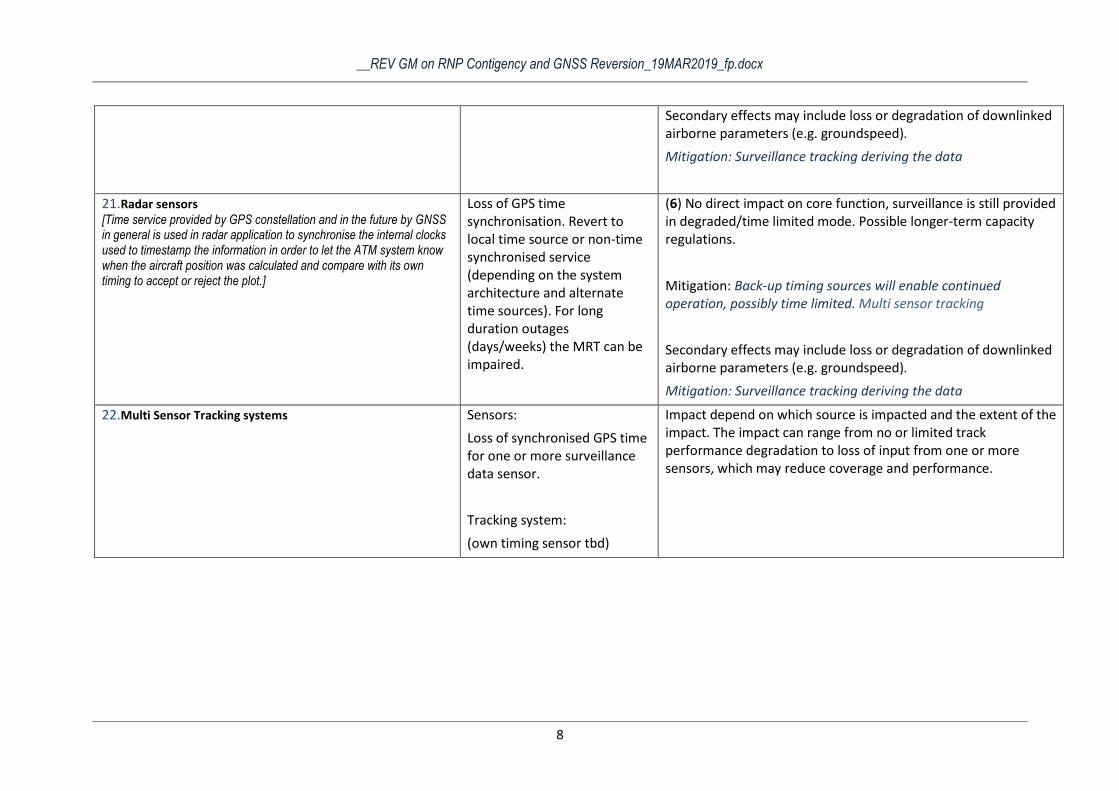
__REV GM on RNP Contigency and GNSS Reversion_19MAR2019_fp.docx
8
Secondary effects may include loss or degradation of downlinked airborne parameters (e.g. groundspeed).
Mitigation: Surveillance tracking deriving the data
21. Radar sensors [Time service provided by GPS constellation and in the future by GNSS in general is used in radar application to synchronise the internal clocks used to timestamp the information in order to let the ATM system know when the aircraft position was calculated and compare with its own timing to accept or reject the plot.]
Loss of GPS time synchronisation. Revert to local time source or non-time synchronised service (depending on the system architecture and alternate time sources). For long duration outages (days/weeks) the MRT can be impaired.
(6) No direct impact on core function, surveillance is still provided in degraded/time limited mode. Possible longer-term capacity regulations.
Mitigation: Back-up timing sources will enable continued operation, possibly time limited. Multi sensor tracking
Secondary effects may include loss or degradation of downlinked airborne parameters (e.g. groundspeed).
Mitigation: Surveillance tracking deriving the data
22. Multi Sensor Tracking systems Sensors:
Loss of synchronised GPS time for one or more surveillance data sensor.
Tracking system:
(own timing sensor tbd)
Impact depend on which source is impacted and the extent of the impact. The impact can range from no or limited track performance degradation to loss of input from one or more sensors, which may reduce coverage and performance.


__REV GM on RNP Contigency and GNSS Reversion_19MAR2019_fp.docx
2
APPENDIX 2 – Conclusion of Budapest Simulations
RAW TEXT (UNEDITED) Excerpt from email from SALABERT>PAVLICEVIC
Conclusions if the Budapest RTS to extract some input that could be useful for the European GNSS contingency/reversion handbook..
Anyhow, these operational considerations/mitigations are relevant to NETOPS and could be useful for further updates/iterations in the document:
Procedures
Coordination procedures between TWR, APP, ACC in case of GPS outage have to be in place.
These procedures shall consider holding aircraft on the ground before departure,
coordination of GPS only flights in case of a go-around.
Clear procedures need to be in place in case of GPS outage for the NMOC and ATC as well as for
coordination with the military ATC regarding TRAs.
ATC phraseology has to be defined for the case of a GPS outage: confirmation of aircraft capability
to follow RNAV trajectories in en-route airspace or confirmation of aircraft
capability to follow a given SID or STAR in case of GPS outage.
Phraseology has to be defined for the case of a GPS outage event for flight crew to verify the
degradation of navigational capabilities.
Procedures need to consider the fact that the same GPS outage would trigger different messages to
flight crew depending on avionics configuration.
Support tools.
Further analysis is needed to confirm the operational need to develop tools for notifying Air-Traffic
Controllers, Supervisors and NMOC of GPS outages. It is recommended to define and validate the
capabilities of the tools.
o Supporting tool allowing the detection of the GPS outage and informing ATC, the
need for information about a GPS outage depends on the level of the user in the ATM
system (e.g. Information at FIR level for a supervisor of an ACC or information at European airspace level for
the NMOC) to have the adequate situational awareness to apply adequate contingency measures (e.g.
apply capacity restrictions considering sectors affected over time). This relates to the requirement in
the NMF IR to have information on the operational availability of GNSS services.
o HMI indication could notify the controller of a GNSS outage in a sector directly on his/her screen.
o Some kind of indication on the HMI should be possible to highlight which aircraft are not
capable to navigate as requiered (e.g. loss RNAV capability) and need radar vectoring.
This indication should be visible already when the aircraft is entering the sector, to save
on coordination with the neighboring sector. Flight plan information could be used by
ATM systems to inform ATCOs with a label for GPS only aircraft in their sectors to
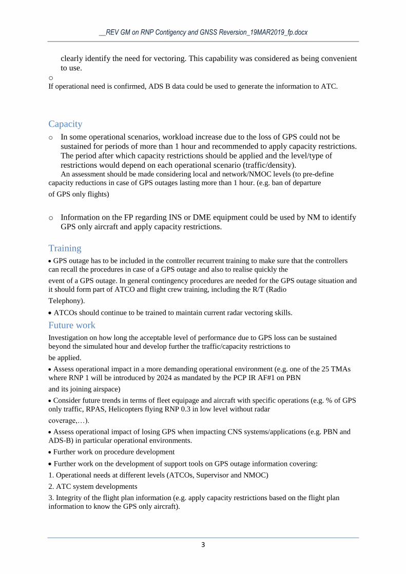
__REV GM on RNP Contigency and GNSS Reversion_19MAR2019_fp.docx
3
clearly identify the need for vectoring. This capability was considered as being convenient
to use.
o If operational need is confirmed, ADS B data could be used to generate the information to ATC.
Capacity
o In some operational scenarios, workload increase due to the loss of GPS could not be
sustained for periods of more than 1 hour and recommended to apply capacity restrictions.
The period after which capacity restrictions should be applied and the level/type of
restrictions would depend on each operational scenario (traffic/density). An assessment should be made considering local and network/NMOC levels (to pre-define
capacity reductions in case of GPS outages lasting more than 1 hour. (e.g. ban of departure
of GPS only flights)
o Information on the FP regarding INS or DME equipment could be used by NM to identify
GPS only aircraft and apply capacity restrictions.
Training
GPS outage has to be included in the controller recurrent training to make sure that the controllers
can recall the procedures in case of a GPS outage and also to realise quickly the
event of a GPS outage. In general contingency procedures are needed for the GPS outage situation and
it should form part of ATCO and flight crew training, including the R/T (Radio
Telephony).
ATCOs should continue to be trained to maintain current radar vectoring skills.
Future work
Investigation on how long the acceptable level of performance due to GPS loss can be sustained
beyond the simulated hour and develop further the traffic/capacity restrictions to
be applied.
Assess operational impact in a more demanding operational environment (e.g. one of the 25 TMAs
where RNP 1 will be introduced by 2024 as mandated by the PCP IR AF#1 on PBN
and its joining airspace)
Consider future trends in terms of fleet equipage and aircraft with specific operations (e.g. % of GPS
only traffic, RPAS, Helicopters flying RNP 0.3 in low level without radar
coverage,…).
Assess operational impact of losing GPS when impacting CNS systems/applications (e.g. PBN and
ADS-B) in particular operational environments.
Further work on procedure development
Further work on the development of support tools on GPS outage information covering:
1. Operational needs at different levels (ATCOs, Supervisor and NMOC)
2. ATC system developments
3. Integrity of the flight plan information (e.g. apply capacity restrictions based on the flight plan
information to know the GPS only aircraft).
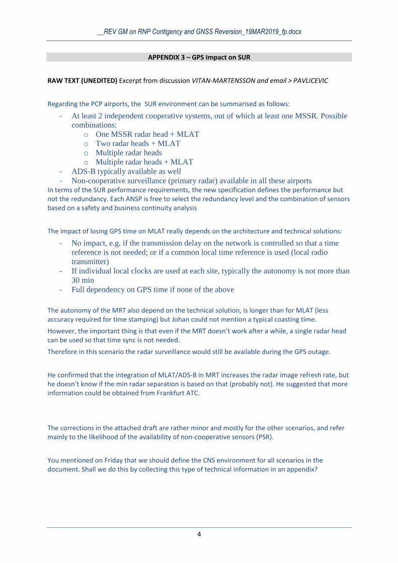
__REV GM on RNP Contigency and GNSS Reversion_19MAR2019_fp.docx
4
APPENDIX 3 – GPS Impact on SUR
RAW TEXT (UNEDITED) Excerpt from discussion VITAN-MARTENSSON and email > PAVLICEVIC
Regarding the PCP airports, the SUR environment can be summarised as follows:
- At least 2 independent cooperative systems, out of which at least one MSSR. Possible
combinations:
o One MSSR radar head + MLAT
o Two radar heads + MLAT
o Multiple radar heads
o Multiple radar heads + MLAT
- ADS-B typically available as well
- Non-cooperative surveillance (primary radar) available in all these airports In terms of the SUR performance requirements, the new specification defines the performance but not the redundancy. Each ANSP is free to select the redundancy level and the combination of sensors based on a safety and business continuity analysis
The impact of losing GPS time on MLAT really depends on the architecture and technical solutions:
- No impact, e.g. if the transmission delay on the network is controlled so that a time
reference is not needed; or if a common local time reference is used (local radio
transmitter)
- If individual local clocks are used at each site, typically the autonomy is not more than
30 min
- Full dependency on GPS time if none of the above
The autonomy of the MRT also depend on the technical solution, is longer than for MLAT (less accuracy required for time stamping) but Johan could not mention a typical coasting time.
However, the important thing is that even if the MRT doesn’t work after a while, a single radar head can be used so that time sync is not needed.
Therefore in this scenario the radar surveillance would still be available during the GPS outage.
He confirmed that the integration of MLAT/ADS-B in MRT increases the radar image refresh rate, but he doesn’t know if the min radar separation is based on that (probably not). He suggested that more information could be obtained from Frankfurt ATC.
The corrections in the attached draft are rather minor and mostly for the other scenarios, and refer mainly to the likelihood of the availability of non-cooperative sensors (PSR).
You mentioned on Friday that we should define the CNS environment for all scenarios in the document. Shall we do this by collecting this type of technical information in an appendix?