european technical approval eta-11/0313 - globprot eta.pdf · member of eota european technical...
TRANSCRIPT

P900169
E u r o p e a n O r g a n i s a t i o n fo r Te c h n i c a l Ap p r o v a l s
SITAC
Box 553
SE 371 23 Karlskrona
SWEDEN
Tfn.: +46-(0)10-516 63 00
Fax: +46-(0)455-206 88
E-mail: [email protected]
MEMBER OF EOTA
European Technical Approval ETA-11/0313
Handelsnamn Trade name
Roxtec Modular Penetration Sealing System
Roxtec Modular Penetration Sealing System
Innehavare Holder of approval
Roxtec International AB
Box 540
SE-371 23 Karlskrona
Sweden
Produktbeskrivning och avsedd
användning
Modulärt tätningssystem för genomföringar i
brandavskiljande väggar och bjälklag i byggnader
Generic type and use
of construction product
Modular penetration seal for fire resistant walls and floors
in buildings
Giltighetstid Validity:
från from
2011-12-16 16.12.2011
t o m to
2016-12-15 15.12.2016
Tillverkningsställe Manufacturing plant
Roxtec International AB
Karlskrona, Sweden
Godkännandet innehåller
This Approval contains 27 sidor inklusive 3 bilagor 27 Pages including 3 Annexes

Page 2 (27) of ETA-11/0313, issued on 16.12.2011
P900169
TABLE OF CONTENTS
I LEGAL BASIS AND GENERAL CONDITIONS 3
II SPECIFIC CONDITIONS OF THE EUROPEAN TECHNICAL APPROVAL 4
1 Definition of product(s) and intended use
1.1 Definition of the construction product 4
1.2 Intended use and use category 4
2 Characteristics of the product(s) and methods of verification
2.1 ER 1 Mechanical resistance and stability 5
2.2 ER 2 Safety in case of fire 5
2.3 ER 3 Hygiene, health and environment 5
2.4 ER 4 Safety in use 6
2.5 ER 5 Protection against noise 6
2.6 ER 6 Energy economy and heat retention 6
2.7 Durability and serviceability 6
3 Evaluation and attestation of conformity and CE-marking
3.1 System of attestation of conformity 7
3.2 Responsibilities 7
3.3 CE marking 9
4 Assumptions under which the fitness of the product(s) for the intended use
was favourably assessed
4.1 Manufacturing 10
4.2 Installation 10
5 Indications of the manufacturer
5.1 Packaging, transport and storage 16
5.2 Use, maintenance, repair 16
Annex A Resistance to fire classification of Roxtec Modular Penetration Sealing System
Annex B Drawings
Annex C Services
Annex D Detailed design specifications for components

Page 3 (27) of ETA-11/0313, issued on 16.12.2011
P900169
I LEGAL BASIS AND GENERAL CONDITIONS
1 This European Technical Approval is issued by SITAC in accordance with:
Council Directive 89/106/EEC of 21 December 1988 on the approximation of laws,
regulations and administrative provisions of Member States relating to construction
products1, modified by Council Directive 93/68/EEC
2 and Regulation (EC) N°
1882/2003 of the European Parliament and of the Council3;
Common Procedural Rules for Requesting, Preparing and the Granting of European
Technical Approvals set out in the Annex to Commission Decision 94/23/EC4;
Guideline for European Technical Approval of Fire Stopping and Fire Sealing
Products: ETAG 026 Part 1: “General” and Part 2: “Penetration Seals”.
2 The SITAC is authorized to check whether the provisions of this European Technical Approval
are met. Checking may take place in the manufacturing plant(s). Nevertheless, the responsibility
for the conformity of the products to the European Technical Approval and for their fitness for
the intended use remains with the holder of the European Technical Approval.
3 This European Technical Approval is not to be transferred to manufacturers or agents of
manufacturers other than those indicated on page 1, or manufacturing plants other than those
indicated on page 1 of this European Technical Approval.
4 This European Technical Approval may be withdrawn by SITAC, in particular pursuant to
information by the Commission according to Article 5(1) of Council Directive 89/106/EEC.
5 Reproduction of this European Technical Approval including transmission by electronic means
shall be in full. However, partial reproduction can be made with the written consent of SITAC. In
this case partial reproduction has to be designated as such. Texts and drawings of advertising
brochures shall not contradict or misuse the European Technical Approval.
6 The European Technical Approval is issued by the approval body in English. This version
corresponds fully to the version circulated within EOTA. Translations into other languages have
to be designated as such.
1 Official Journal of the European Communities L 40, 11.2.1989, p. 12
2 Official Journal of the European Communities L 220, 30.8.1993, p. 1
3 Official Journal of the European Union L 284, 31.10.2003, p. 1
4 Official Journal of the European Communities L 17, 20.1.1994, p. 34

Page 4 (27) of ETA-11/0313, issued on 16.12.2011
P900169
II SPECIFIC CONDITIONS OF THE EUROPEAN TECHNICAL
APPROVAL
1 Definition of product(s) and intended use
1.1 Definition of the construction product
This European Technical Approval refers to cable penetration seal with the designation “Roxtec
Modular Penetration Sealing System
The Roxtec Modular Penetration Sealing System consists of rectangular frames: G Frame and B frame
and round frames: R frame (multiple cables) and RS series (single cables). The frames are used
together with elastometric blocks and a compression unit.
The frames can either be cast, bolted, welded or fitted into sleeves. The frames and other steel
components are of stainless steel or galvanised steel. Steel sleeves are also available in coated mild
steel.
Details of the systems are shown in Annex A-B.
Detailed design specifications for components are shown in the supporting document Annex D.
Annex D is a formal part of the ETA, and the valid version of the document is the latest version filed
by SITAC.
1.2 Intended use and use category
The intended use of Roxtec Modular Penetration Sealing System is to reinstate the fire resistance
performance of flexible and rigid wall constructions and rigid floor constructions, where they are
penetrated by various cables.
Details of the supporting constructions, cables etc are shown in Annex A-C.
The provisions made in this European Technical Approval are based on an assumed working life of the
Roxtec Modular Penetration Sealing System of 25 years. The indications given on the working life
cannot be interpreted as a guarantee given by the producer, but are to be regarded only as a means for
choosing the right products in relation to the expected economically reasonable working life of the
works.
Use category
The use category of Roxtec Modular Penetration Sealing System is
Type X, for the system with components made of stainless steel or galvanised steel
and
Type Z2, for the system with components made of coated mild steel
Type X: intended for use in conditions exposed to weathering

Page 5 (27) of ETA-11/0313, issued on 16.12.2011
P900169
Type Y1: intended for use at temperatures below 0°C with exposure to UV but no exposure to rain
Type Y2: intended for use at temperatures below 0°C, but with no exposure to rain nor UV
Type Z1: intended for use in internal conditions with humidity equal to or higher than 85 % RH, excluding temperatures
below 0°C. These uses apply for internal humidity class 5 in accordance with EN ISO 13788
Type Z2: intended for uses in internal conditions with humidity lower than 85 % RH, excluding temperatures below 0°C
Note: Products that meet requirements for type X, meet the requirements for all other types. Products that meet
requirements for type Y1 also meet the requirements for type Y2, Z1 and Z2. Products that meet the requirements
for type Y2 also meet the requirements for type Z1 and Z2. Products that meet the requirements for type Z1, also
meet the requirements for type Z2.
2 Characteristics of product(s) and methods of verification
The characteristics given in this chapter are applicable to all combinations of materials, components
and dimensions described in this ETA if no other provisions are specified.
Provisions shall be taken such that floor penetration seals cannot be stepped on, e.g. by covering with a
wire mesh.
The service support construction shall be fixed to the building element on both sides of the penetration
in such a manner that in the case of fire no additional load is imposed on the seal. Furthermore it is
assumed that this support is maintained for the required period of fire resistance.
2.1 ER 1 Mechanical resistance and stability
Not relevant
2.2 ER 2 Safety in case of fire
2.2.1 Reaction to fire
No performance determined thereby classified F in accordance with EN 13501-1.
2.2.2 Resistance to fire
The Roxtec Modular Penetration Sealing System has been tested in accordance with en 1366-3:2009
and classified in accordance with EN 13501-2, as given in Annex A.
2.3 ER 3 Hygiene, health and environment
No performance determined
2.3.1 Air permeability
No performance determined

Page 6 (27) of ETA-11/0313, issued on 16.12.2011
P900169
2.3.2 Water permeability
No performance determined
2.3.3 Dangerous substances
No performance determined
2.4 ER 4 Safety in use
2.4.1 Mechanical resistance and stability
No performance determined
2.4.2 Resistance to impact/movement
No performance determined
2.4.3 Adhesion
No performance determined
2.5 ER 5 Protection against noise
2.5.1 Airborne sound insulation
No performance determined
2.6 ER 6 Energy economy and heat retention
2.6.1 Thermal properties
No performance determined
2.6.2 Water vapour permeability
No performance determined
2.7 Durability and serviceability
Roxtec Modular Penetration Sealing System has been tested in accordance with EOTA Technical
Report – TR024 – Edition 2009-07 and ETAG 026-2 for the type X and Z2 use categories. The results
were:
Type X for the system with components of stainless steel and galvanised steel: intended for use at
conditions exposed to weathering
Type Z2 for the system with components of coated mild steel: intended for use in internal conditions
with humidity lower than 85 % RH, excluding temperatures below 0°C
Page 7 (27) of ETA-11/0313, issued on 16.12.2011
P900169
3 Evaluation and attestation of conformity and CE-marking
3.1 System of attestation of conformity
According to the Decision 1999/454/EC of the European Commission5 system 1 of the attestation of
conformity applies.
This system of attestation of conformity is defined as follows:
System 1: Certification of the conformity of the product by an approved certification body on the basis
of:
(a) Tasks for the manufacturer:
(1) factory production control;
(2) further testing of samples taken at the factory by the manufacturer in accordance with a
prescribed test plan;
(b) Tasks for the approved body:
(3) initial type–testing of the product;
(4) initial inspection of factory and of factory production control;
(5) continuous surveillance, assessment and approval of factory production control.
3.2 Responsibilities
3.2.1 Tasks of the manufacturer
3.2.1.1 Factory production control
The manufacturer shall exercise permanent internal control of production. All the elements, require-
ments and provisions adopted by the manufacturer shall be documented in a systematic manner in the
form of written policies and procedures, including records of results performed. This production
control system shall insure that the product is in conformity with this European Technical Approval.
The manufacturer may only use constituent materials stated in the technical documentation of this
European Technical Approval.
The factory production control shall be in accordance with the "Control Plan" which is part of the
technical documentation of this European Technical Approval. The "Control Plan" is laid down in the
context of the factory production control system operated by the manufacturer and deposited at the
SITAC.6
The results of factory production control shall be recorded and evaluated in accordance with the
provisions of the "Control Plan".
5 Official Journal of the European Communities No L 178, 14,7,1999, p. 52
6 The "Control Plan" is a confidential part of the European Technical Approval and only handed over to the approved body
or bodies involved in the procedure of attestation of conformity. See section 3.2.2.

Page 8 (27) of ETA-11/0313, issued on 16.12.2011
P900169
3.2.1.2 Other tasks of manufacturer
The manufacturer shall, on the basis of a contract, involve a body (bodies) which is (are) approved for
the tasks referred to in section 3.1 in the field of penetration seals in order to allow the manufacturer to
undertake the actions laid down in section 3.3. For this purpose, the "Control Plan" referred to in
sections 3.2.1.1 and 3.2.2 shall be handed over by the manufacturer to the approved body or bodies
involved.
The manufacturer shall make a declaration of conformity, stating that the construction product is in
conformity with the provisions of the European Technical Approval ETA-11/0313 issued on
16.12.2011.
Additional information
The manufacturer shall provide a technical data sheet and installation instruction with the following
minimum information:
Technical data sheet:
Field of application:
- Building elements for which the penetration seal is suitable, type and properties of the building
elements like minimum thickness, density, and – in case of lightweight constructions – the
construction requirements.
- Services for which the penetration seal is suitable, type and properties of the services like
material, diameter, thickness etc. in case of pipes including insulation materials;
necessary/allowed supports/fixings (e.g. cable trays)
- Limits in size, minimum thickness etc. of the penetration seal
Construction of the penetration seal including the necessary components and additional products
(e.g. backfilling material) with clear indication where they are generic or specific.
Installation instruction:
Steps to be followed
Procedure in case of retrofitting
Stipulations on maintenance, repair and replacement
3.2.2 Tasks of approved bodies
The approved body (bodies) shall perform the
- initial type-testing of the product,
- initial inspection of factory and of factory production control,
- continuous surveillance, assessment and approval of factory production control,
in accordance with the provisions laid down in the "Control Plan" relating to the European Technical
Approval ETA-11/0313 issued on 16.12.2011.
The approved body (bodies) shall retain the essential points of its (their) actions referred to above and
state the results obtained and conclusions drawn in (a) written report (reports).
The approved certification body involved by the manufacturer shall issue an EC certificate of confor-
mity of the product stating the conformity with the provisions of this European Technical Approval.

Page 9 (27) of ETA-11/0313, issued on 16.12.2011
P900169
In cases where the provisions of the European Technical Approval and its "Control Plan" are no longer
fulfilled the certification body shall withdraw the certificate of conformity and inform the SITAC
without delay.
3.3 CE marking
The CE marking shall be affixed on the smallest packaging unit. The marking „CE“ shall be followed
by the identification number of the approved certification body and be accompanied by the following
additional information:
- the name and address of the producer (legal entity responsible for the manufacturer),
- the last two digits of the year in which the CE marking was affixed,
- the number of the EC certificate of conformity for the product,
- the number of the European Technical Approval,
- the number of the guideline for European Technical Approval
- the penetration seal name and use category/categories of the product as listed in accordance with
the provisions of the ETAG
Example of CE marking and accompanying information for Roxtec Modular Penetration System:
"CE"-marking
1234 Identification number of approved certification body
Roxtec AB
Rombvägen 2,
Karlskrona,
Sweden
Name and address of the producer (legal entity responsible for the
manufacturer)
04 Two last digits of year of affixing the CE marking
1234-CPD-0321 Number of EC certificate of conformity
ETA-11/0313 Number of European Technical Approval
ETAG N° 026 part 2 Number of guideline for European Technical Approval
Roxtec Modular
Penetration Sealing
System
Name
“see ETA-11/0313 for
relevant characteristics” Reference to ETA for relevant characteristics
All information above is shown on a label attached to the packaging.

Page 10 (27) of ETA-11/0313, issued on 16.12.2011
P900169
4 Assumptions under which the fitness of the product(s) for the intended use was favourably
assessed
4.1 Manufacturing
The European Technical Approval is issued for the product on the basis of agreed data/information,
deposited with the SITAC, which identifies the product that has been assessed and judged. Changes to
the product or production process, which could result in this deposited data/information being
incorrect, shall be notified to the SITAC before the changes are introduced. The SITAC will decide
whether or not such changes affect the ETA and consequently the validity of the CE marking on the
basis of the ETA and if so whether further assessment or alterations to the ETA, shall be necessary.
4.2 Installation
Installation of the Roxtec Modular Penetration Sealing System should be performed in accordance to
the following installation instructions:
Insulation placed in cavities is packed in place. Insulation placed around cables is fixed in position by
using a wire which will keep the insulation in place even if exposed to fire.
The insulation around cables is put around the cable with an overlap of approx. 50 mm in order to
avoid gaps in the insulation into the cable. The wire used is placed around the insulation and tightened,
checking for gaps in the insulation towards the cable. As described before, the use of a wire, is to keep
the insulation in place in order to avoid for the insulation to slide of or loosen. The wire should be
placed with an approximate CC distance of 100 mm. In general minimum 2 wires should be used
securing the insulation. After the insulation is secured and tightened around the cables, the insulation is
pushed towards the sealing as much as possible to avoid a gap between insulation of the seal and
insulation of the cables.
4.2.1 Roxtec R frame

Page 11 (27) of ETA-11/0313, issued on 16.12.2011
P900169
4.2.2 Roxtec RS seal

Page 12 (27) of ETA-11/0313, issued on 16.12.2011
P900169
4.2.3 Roxtec Wedge/G frame

Page 13 (27) of ETA-11/0313, issued on 16.12.2011
P900169
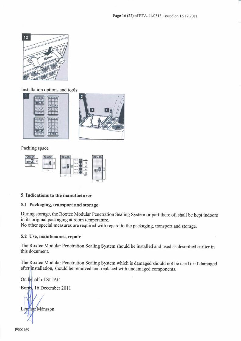
Installation options and tools
Packaging space
4.2.4 Roxtec B frame
Frame assembly

Page 14 (27) of ETA-11/0313, issued on 16.12.2011
P900169
Installation, casting
Installation, bolting
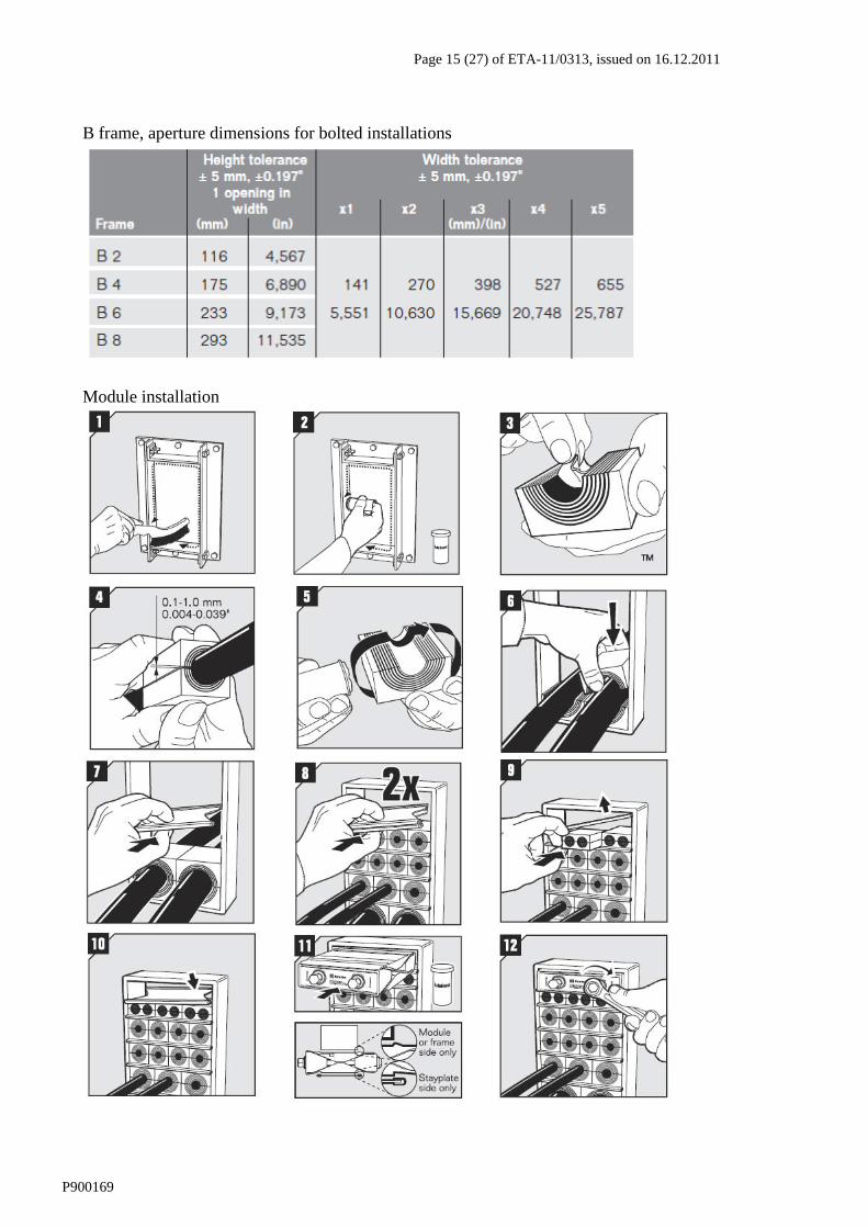
Page 15 (27) of ETA-11/0313, issued on 16.12.2011
P900169
B frame, aperture dimensions for bolted installations
Module installation

Page 17 (27) of ETA-11/0313, issued on 16.12.2011
P900169
Annex A -
Resistance to fire classification of Roxtec Modular Penetration Sealing System:
A.1 R frame
A.1.1 System description
The element R frame in different sizes (R 70, R 75, R 100, R 125, R 127, R 150 and R 200) is
constructed of a set of components: a flanged steel frame, stone wool insulation, a sealing compound
(Roxtec Lubricant), screws and a system of elastometric blocks and a compression device. The
allowable elastometric blocks are RM 30 and RM 40 of thickness 60 mm. The element is
unsymmetrical with the flange of the steel sleeves on one side and the stone wool insulation on the
other side of the element. The system is shown in the drawing no. S1022840, see annex B1.
A.1.1.1 Supporting constructions
The floor is to be classified in at least EI 60 in accordance with EN 13501-2
All other information is shown in annex B1.
A.1.1.2 Seal size
Maximum size of the single opening is 202 mm.
A.1.1.3 Number of penetrations
In cases where several elements are included in a single floor the minimum distance between two
adjacent elements is 200 mm.
A.1.1.4 Cables
See the annex B1 and C
A.1.1.5 Insulation of the steel frame and the cables
The insulation shall be made of stone wool with density 100 kg/m3 and CE marked in class A1 in
accordance to EN 13163 or EN 14303.
See also the annex B1
A.1.1.6 Fire resistant sealant
The fire resistant sealant should be a one-component low-modulus silicone rubber which is to be used
for cable penetrations through floors which is to be fire-rated EI 60. The sealant should be classed for
usage on constructions made of concrete.
Reaction to fire classification: requirement R2; hazard level HL1 and HL2 in accordance with CEN/TS
45545-2.
The sealant should be installed according to the supplier’s installation guides.
A.1.1.7 Service support construction
See the annex B1
A.1.1.8 Blank seals
Allowed
A.1.2 Resistance to fire classification
EI 60 in accordance to EN 13501-2

Page 18 (27) of ETA-11/0313, issued on 16.12.2011
P900169
A.2 RS series
A.2.1 System description
The element RS series (RS 31-RS 125) is constructed of a set of components: a flanged steel sleeve
with a rubber frame, a rubber core and a compression device, stone wool insulation, a sealing
compound (Roxtec Lubricant) and screws. The element is unsymmetrical with the flange of the steel
sleeves on one side and the stone wool insulation on the other side of the elements. The system is
shown in the drawing no. S1022819, see annex B2.
A.2.1.1 Supporting constructions
- The wall and floor is to be classified in at least EI 60 in accordance with EN 13501-2
- Flexible walls with timber studs shall be mounted with a minimum distance of 100 mm to the studs,
the cavities between the aperture framing and the studs shall be closed and minimum 100 mm
insulation of class A1 or A2 according to EN 13501-1 and shall be provided within the cavities
between the aperture framing and the studs of the wall.
All other information is shown in annex B2.
A.2.1.2 Seal size
Maximum size of the single opening is 127 mm.
A.2.1.3 Number of penetrations
In cases where several elements are included in a single wall the minimum distance between two
adjacent elements is 200 mm.
A.2.1.4 Aperture framing
Flexible walls shall be constructed with aperture framing consisting of lintel transoms and lintel studs.
The lintel transoms are mounted between two adjacent studs of the wall and the lintel studs are
mounted between the upper and lower transoms. The lintels are minimum 0,7 mm thick rolled steel C-
studs. The space between the lintels, the boards and the sleeves of the elements is filled with stone
wool insulation of class A1 in accordance to EN 13501-1.
A.2.1.5 Cables
See the annex B2 and C
A.2.1.6 Insulation of the sleeve and cables
The insulation shall be made of stone wool with density 100 kg/m3 and CE marked in class A1 in
accordance to EN 13163 or EN 14303.
See also the annex B2
A.2.1.7 Fire resistant sealant
The fire resistant sealant should be a one-component low-modulus silicone rubber which is to be used
for cable penetrations through walls and floors which is to be fire-rated EI 60. The sealant should be
classed for usage on constructions made of concrete and gypsum.
Reaction to fire classification: requirement R2; hazard level HL1 and HL2 in accordance with CEN/TS
45545-2.
The sealant should be installed according to the supplier’s installation guides.

Page 19 (27) of ETA-11/0313, issued on 16.12.2011
P900169
A.2.1.8 Service support construction
See the annex B2
A.2.1.9 Blank seals
Allowed
A.2.2 Resistance to fire classification
EI 60 in accordance to EN 13501-2

Page 20 (27) of ETA-11/0313, issued on 16.12.2011
P900169
A.3 G Frame
A.3.1 System description
The element G Frame is constructed of a set of components: a flanged steel combination frame, stone
wool insulation, a sealing compound (Roxtec Lubricant), screws and a system of elastometric blocks
and one or more compression devices. The allowable elastometric blocks are RM 20, RM 20W40, RM
30, RM 40, RM 60, RM 90 and RM 120 of 60 mm thickness. The element is unsymmetrical with the
flange of the steel frame on one side and the stone wool insulation on the other side of the element.
The system is shown in the drawing no. S1022839, see annex B3.
A.3.1.1 Supporting constructions
- The wall and floor is to be classified in at least EI 60 in accordance with EN 13501-2
- Flexible walls with timber studs shall be mounted with a minimum distance of 100 mm to the studs,
the cavities between the aperture framing and the studs shall be closed and minimum 100 mm
insulation of class A1 or A2 according to EN 13501-1 and shall be provided within the cavities
between the aperture framing and the studs of the wall.
All other information is shown in annex B3.
A.3.1.2 Seal size
Maximum size of single opening (width x height): 120 x 278 mm.
A.3.1.3 Number of penetrations
Any number of single openings in rigid walls and rigid floors.
Up to 4 x 1 or 2 x 2 single openings when mounted in flexible walls.
The minimum distance between two adjacent single frames or combination frames is 200 mm.
A.3.1.4 Aperture framing
Flexible walls shall be constructed with aperture framing consisting of lintel transoms and lintel studs.
The lintel transoms are mounted between two adjacent studs of the wall and the lintel studs are
mounted between the upper and lower transoms. The lintels are minimum 0.7 mm thick rolled steel C-
studs. The space between the lintels, the boards and the frames of the elements is filled with stone
wool insulation of class A1 in accordance to EN 13501-1.
A.3.1.5 Cables
See the annex B3 and C
A.3.1.6 Insulation of the steel frame and the cables
The insulation shall be made of stone wool with density 100 kg/m3 and CE marked in class A1 in
accordance to EN 13163 or EN 14303.
See also the annex B3
A.3.1.7 Fire resistant sealant
The fire resistant sealant should be a one-component low-modulus silicone rubber which is to be used
for cable penetrations through walls and floors which is to be fire-rated EI 60. The sealant should be
classed for usage on constructions made of concrete and gypsum.
Reaction to fire classification: requirement R2; hazard level HL1 and HL2 in accordance with CEN/TS
45545-2.
The sealant should be installed according to the supplier’s installation guides.
See also the annex B3

Page 21 (27) of ETA-11/0313, issued on 16.12.2011
P900169
A.3.1.8 Service support construction
See the annex B3
A.3.1.9 Blank seals
Allowed
A.3.2 Resistance to fire classification
EI 60 in accordance to EN 13501-2

Page 22 (27) of ETA-11/0313, issued on 16.12.2011
P900169
A.4 B Frame
A.4.1 System description
The element B Frame is constructed of a set of components: a flanged steel combination frame, stone
wool insulation, a sealing compound (Roxtec Lubricant), screws and a system of elastometric blocks
and one or more compression devices. The allowable elastometric blocks are RM 20, RM 20W40, RM
30, RM 40, RM 60, RM 90 and RM 120 of 60 mm thickness. The element is unsymmetrical with the
flange of the steel frame on one side and the stone wool insulation on the other side of the element.
The system is shown in the drawing no. S1022839, see annex B3.
A.4.1.1 Supporting constructions
- The wall and floor is to be classified in at least EI 60 in accordance with EN 13501-2
- Flexible walls with timber studs shall be mounted with a minimum distance of 100 mm to the studs,
the cavities between the aperture framing and the studs shall be closed and minimum 100 mm
insulation of class A1 or A2 according to EN 13501-1 and shall be provided within the cavities
between the aperture framing and the studs of the wall.
All other information is shown in annex B3.
A.4.1.2 Seal size
Maximum size of single opening (width x height): 120 x 278 mm.
A.4.1.3 Number of penetrations
Any number of single openings in rigid walls and rigid floors. Up to B8 x 4 in flexible walls.
Minimum 200 mm between two adjacent single frames or combination frames.
A.4.1.4 Aperture framing
Flexible walls shall be constructed with aperture framing consisting of lintel transoms and lintel studs.
The lintel transoms are mounted between two adjacent studs of the wall and the lintel studs are
mounted between the upper and lower transoms. The lintels are minimum 0.7 mm thick rolled steel C-
studs. The space between the lintels, the boards and the frames of the elements is filled with stone
wool insulation of class A1 in accordance to EN 13501-1.
A.4.1.5 Cables
See the annex B3 and C
A.4.1.6 Insulation of the steel frame and the cables
The insulation shall be made of stone wool with density 100 kg/m3 and CE marked in class A1 in
accordance to EN 13163 or EN 14303.
See also the annex B3
A.4.1.7 Fire resistant sealant
The fire resistant sealant should be a one-component low-modulus silicone rubber which is to be used
for cable penetrations through walls and floors which is to be fire-rated EI 60. The sealant should be
classed for usage on constructions made of concrete and gypsum.
Reaction to fire classification: requirement R2; hazard level HL1 and HL2 in accordance with CEN/TS
45545-2.
The sealant should be installed according to the supplier’s installation guides.
See also the annex B3

Page 23 (27) of ETA-11/0313, issued on 16.12.2011
P900169
A.4.1.8 Service support construction
See the annex B3
A.4.1.9 Blank seals
Allowed
A.4.2 Resistance to fire classification
EI 60 in accordance to EN 13501-2


Page 27 (27) of ETA-11/0313, issued on 16.12.2011
P900169
Annex C - Services Cable
type
Dimensions Designation Standard Insulation /
sheath material
A1 5 x 1,5 mm2 bfb HD
603.3
PVC / PVC b
A2 5 x 1,5 mm2 bff HD 22.4 EPR / PO d
A3 5 x 1,5 mm2 bfdb HD
604.5
XLPE / EVA f
B 1 x 95 mm2 bbff HD
603.3
HD 603.3
C1 4 x 95 mm2 HD 22.4 PVC / PVC b
C2 4 x 95 mm2 H07RN-F 4G95 HD 22.4 EPR / PO d
C3 4 x 95 mm2 YMz1Kmbzh 0,6/1 kV 4G95
PVIK-LS-HF 4x95
N2XH-J 4x95SM or N2XH-O
4x95SM
n.n.
E-NGNG-J 4x95SM or E-3G3G-J
4x95SM or
E-NGNG-O 4x95SM or E-3G3G-O
4x95SM
HD
604.5
XLPE / EVA f
D1 4 x 185 mm2 E-YCWY 4x185SM/95
MCMK 4x815/95
NYCWY 4x185SM/95
PFSP CU 4x185/95
FKKJ 4x185/95 S
HD
603.3
PVC / PVC b
D2 4 x 185 mm2 H07RN-F 4G185 EPR / PO d
D3 4 x 185 mm2 YMz1Kmbzh 0,6/1 kV 4G185 svs
PVIK-LS-HF 4x185
N2XH-J 4x185SM or N2XH-O
4x185SM
n.n.
E-NGNG-J 4x185SM or E-3G3G-J
4x185SM or
E-NGNG-O 4x185SM or E-3G3G-
O 4x185SM
HD
604.5
XLPE /EVA f
E 1 x 185 mm2 E-YY-J 1x185RM or E-YY-O
1x185RM
NYY-J 1x185RM or NYY-O
1x185RM
VV 1x185
TT 1x185 RM 0,6/1 kV
HD
603.3
PVC / PVC b
F 20 x 2 mm2 x
0,6 mm
screened
- PE / PE m
b PVC = Polyvinyl chloride
d EPR = Ethylene-propylene rubber compound, PO = Polyolefin, synthetic rubber compound
f XLPE = Cross-linked Polyethylene, EVA = Ethylene-vinyl-acetate copolymer compound
m PE = Polyethylene, solid or cellular