european technical approval eta-13/0436 · post installed rebar connections diameter 8 to 20 mm...
TRANSCRIPT

Centre Scientifique et Technique du Bâtiment 84 avenue Jean Jaurès Champs sur Marne F-77447 Marne-la-Vallée Cedex 2 Tél. : (33) 01 64 68 82 82 Fax : (33) 01 60 05 70 37
Autorisé etnotifié conformément à
l’article 10 de la directive89/106/EEC du Conseil, du
21 décembre 1988, relative aurapprochement des dispositions
législatives, réglementaireset administratives des Etats
membres concernantles produits deconstruction.
MEMBRE DE L’EOTA
European Technical Approval ETA-13/0436
(English language translation, the original version is in French language)
Nom commercial : Trade name:
Injection System Spit MULTI-MAX for rebar connection
Titulaire : Holder of approval:
Société SPIT Route de Lyon F-26501 BOURG-LES-VALENCE France
Type générique et utilisation prévue du produit de construction :
Scellement d’armatures rapportées, diamètres 8 à 20 mm à l’aide de la résine SPIT MULTI-MAX
Generic type and use of construction product:
Post installed rebar connections diameter 8 to 20 mm made with SPIT MULTI-MAX injection mortar.
Validité du : au : Validity from / to:
31/05/2013 31/05/2018
Usine de fabrication : Manufacturing plant:
Société SPIT Route de Lyon F-26501 BOURG-LES-VALENCE France
Le présent Agrément technique européen contient :
This European Technical Approval contains:
22 pages incluant 12 annexes faisant partie intégrante du document.
22 pages including 12 annexes which form an integral part of the document.
Organisation pour l’Agrément Technique Européen European Organisation for Technical Approvals
Page 2 of European Technical Approval ETA-13/0436 dated 31/05/2013 English translation prepared by CSTB
I LEGAL BASES AND GENERAL CONDITIONS
1 This European Technical Approval is issued by the Centre Scientifique et Technique du Bâtiment in accordance with:
Council Directive 89/106/EEC of 21 December 1988 on the approximation of laws, regulations and administrative provisions of Member States relating to construction products1, modified by the Council Directive 93/68/EEC of 22 July 19932 and Regulation (EC) N° 1882/2003 of the European Parliament and of the Council 3;
Décret n° 92-647 du 8 juillet 19924 concernant l’aptitude à l’usage des produits de construction;
Common Procedural Rules for Requesting, Preparing and the Granting of European Technical Approvals set out in the Annex of Commission Decision 94/23/EC5;
Guideline for European Technical Approval of « Metal Anchors for use in Concrete » ETAG 001, edition 1997, Part 1 « Anchors in general », Part 5 « Bonded anchors» and Technical Report for Post Installed Rebar Connections TR23.
2 The Centre Scientifique et Technique du Bâtiment is authorised to check whether the provisions of this European Technical Approval are met. Checking may take place in the manufacturing plant (for example concerning the fulfilment of assumptions made in this European Technical Approval with regard to manufacturing). Nevertheless, the responsibility for the conformity of the products with the European Technical Approval and for their fitness for the intended use remains with the holder of the European Technical Approval.
3 This European Technical Approval is not to be transferred to manufacturers or agents of manufacturer other than those indicated on page 1; or manufacturing plants other than those indicated on page 1 of this European Technical Approval.
4 This European Technical Approval may be withdrawn by the Centre Scientifique et Technique du Bâtiment pursuant to Article 5 (1) of the Council Directive 89/106/EEC.
5 Reproduction of this European Technical Approval including transmission by electronic means shall be in full. However, partial reproduction can be made with the written consent of the Centre Scientifique et Technique du Bâtiment. In this case partial reproduction has to be designated as such. Texts and drawings of advertising brochures shall not contradict or misuse the European Technical Approval.
6 The European Technical Approval is issued by the approval body in its official language. This version corresponds to the version circulated within EOTA. Translations into other languages have to be designated as such.
1 Official Journal of the European Communities n° L 40, 11.2.1989, p. 12 2 Official Journal of the European Communities n° L 220, 30.8.1993, p. 1 3 Official Journal of the European Union n° L 284, 31.10.2003, p. 25 4 Journal officiel de la République française du 14 juillet 1992 5 Official Journal of the European Communities n° L 17, 20.1.1994, p. 34
Page 3 of European Technical Approval ETA-13/0436 dated 31/05/2013 English translation prepared by CSTB
II SPECIFIC CONDITIONS OF THE EUROPEAN TECHNICAL APPROVAL
1 Definition of product and intended use
1.1 Definition of product
The MULTI-MAX is used for the connection, by anchoring or overlap joint, of reinforcing bars (rebars) in existing structures made of ordinary non-carbonated concrete C12/15 to C50/60. The design of the post-installed rebar connections is done in accordance with EN 1992-1-1 October 2005 (EN 1992-1-1).
Covered are rebar anchoring systems consisting of MULTI-MAX bonding material and an embedded straight deformed reinforcing bar with properties according to Annex C of EN 1992-1-1 and EN 10080; the classes B and C of the rebar are recommended. The ETA covers rebar connections with a diameter, d, from 8 to 20 mm.
1.2 Intended use
The ETA covers applications in non-carbonated concrete C 12/15 to C 50/60 (EN 206-1) only, which are also allowed with straight deformed cast-in bars according to EN 1992-1-1, e.g. those in the following applications:
an overlapping joint with existing reinforcement in a building component, see Figure 1.1 and 1.2 in Annex 2.
anchoring of the reinforcement at a slab or beam support; end support/bearing of a slab designed as simply supported as well as its reinforcement for restraint forces, see Figure 1.3 in Annex 2.
anchoring of reinforcement of building components stressed primarily in compression, see Fig.1.4 in Annex 2.
anchoring of reinforcement to cover the line of acting tensile force, see Figure 1.5 in Annex 2.
The MULTI-MAX anchoring systems can be used with the following limitations:
The rebars can be placed in holes made with hammer drilling technique or compressed air drilling.
The rebars may be used in the following temperature range : -40°C to +40°C (max short term temperature +40°C and max long term temperature +20°C)
According to EN 206-1 the allowable chloride content in concrete is limited to 0.40 % (Cl 0,40) related to cement content.
The rebars may be installed in dry or wet concrete, it must not be in flooded holes.
Overhead installation is not permitted
The fire resistance of post-installed rebar connections is not covered by this ETA.
Fatigue, dynamic or seismic loading of post-installed rebar connections are not covered by this ETA.
The provisions made in this European Technical Approval are based on an assumed intended working life of the rebar connections of 50 years. The indications given on the working life cannot be interpreted as a guarantee given by the producer, but are to be regarded only as a means for choosing the right products in relation to the expected economically reasonable working life of the works.

Page 4 of European Technical Approval ETA-13/0436 dated 31/05/2013 English translation prepared by CSTB
2 Characteristics of product and methods of verification
2.1 Characteristics of product
The MULTI-MAX injection adhesive corresponds to the drawings and provisions that are given in Annexe 1.
The SPIT MULTI-MAX injection adhesive is a two components system. The two components of the injection mortar are delivered in unmixed condition in cartridge of size 280 ml to 410 ml according to Annex 1. Each cartridge is marked with the identifying mark “SPIT MULTI-MAX” with the charge code and the storage life.
2.2. Methods of verification
The assessment of fitness of the rebar connection for the intended use in relation to the requirements for mechanical resistance and stability and safety in use in the sense of the Essential Requirements 1 and 4 has been made in accordance with the « Guideline for European Technical Approval of Metal Anchors for use in Concrete », Part 1 « Anchors in general », Part 5 « Bonded anchors » and Technical Report n° 023 “Assessment of post installed rebar connections”.
In addition to the specific clauses relating to dangerous substances contained in this European Technical Approval, there may be other requirements applicable to the products falling within its scope (e.g. transposed European legislation and national laws, regulations and administrative provisions). In order to meet the provisions of the UE Construction Products Directive, these requirements need also to be complied with, when and where they apply.
3 Evaluation of Conformity and CE marking
3.1 Attestation of conformity system
The system of attestation of conformity 2 (i) (referred to as system 1) according to Council Directive 89/106/EEC Annex III laid down by the European Commission provides:
a) tasks for the manufacturer:
1. factory production control,
2. further testing of samples taken at the factory by the manufacturer in accordance with a prescribed test plan.
b) tasks for the approved body:
3. initial type-testing of the product,
4. initial inspection of factory and of factory production control,
5. continuous surveillance, assessment and approval of factory production control.
3.2 Responsibilities
3.2.1 Tasks of the manufacturer
3.2.1.1.Factory production control
The manufacturer shall have a factory production control system in the plant and shall exercise permanent internal control of production. All the elements, requirements and provisions adopted by the manufacturer are documented in a systematic manner in the form of written policies and procedures. This production control system ensures that the product is in conformity with the European Technical Approval.

Page 5 of European Technical Approval ETA-13/0436 dated 31/05/2013 English translation prepared by CSTB
The manufacturer shall only use raw materials supplied with the relevant inspection documents as laid down in the prescribed test plan6. The incoming raw materials shall be subject to controls and tests by the manufacturer before acceptance. Check of incoming materials shall include control of the inspection documents presented by suppliers.
The frequency of controls and tests conducted during production is laid down in the prescribed test plan taking account of the automated manufacturing process of the product.
The results of factory production control are recorded and evaluated. The records include at least the following information:
designation of the product, basic material and components;
type of control or testing;
date of manufacture of the product and date of testing of the product or basic material and components;
result of control and testing and, if appropriate, comparison with requirements;
signature of person responsible for factory production control.
The records shall be presented to the inspection body during the continuous surveillance. On request, they shall be presented to the Centre Scientifique et Technique du Bâtiment.
Details of the extent, nature and frequency of testing and controls to be performed within the factory production control shall correspond to the prescribed test plan which is part of the technical documentation of this European Technical Approval.
3.2.1.2. Other tasks of the manufacturer
The manufacturer shall, on the basis of a contract, involve a body which is approved for the tasks referred to in section 3.1 in the field of in order to undertake the actions laid down in section 3.2.2. For this purpose, the control plan referred to in sections 3.2.1 and 3.2.2 shall be handed over by the manufacturer to the approved body involved. The manufacturer shall make a declaration of conformity, stating that the construction product is in conformity with the provisions of this European technical approval.
3.2.2 Tasks of approved bodies
3.2.2.1 Initial type-testing of the product
For initial type-testing the results of the tests performed as part of the assessment for the European Technical Approval shall be used unless there are changes in the production line or plant. In such cases the necessary initial type-testing has to be agreed between the Centre Scientifique et Technique du Bâtiment and the approved bodies involved.
The approved certification body involved by the manufacturer shall issue an EC certificate of conformity of the product stating the conformity with the provisions of this European technical approval.
3.2.2.2. Initial inspection of factory and of factory production control
The approved certification body involved by the manufacturer shall ascertain that, in accordance with the prescribed test plan, the factory and the factory production control are suitable to ensure continuous and orderly manufacturing of the anchor according to the specifications mentioned in 2.1 as well as to the Annexes to the European Technical Approval .
3.2.2.3. Continuous surveillance
6 The prescribed test plan has been deposited at the Centre Scientifique et Technique du Bâtiment and is only made available to the approved bodies involved in the conformity attestation procedure.

Page 6 of European Technical Approval ETA-13/0436 dated 31/05/2013 English translation prepared by CSTB
The approved body shall visit the factory at least once a year for regular inspection. It has to be verified that the system of factory production control and the specified automated manufacturing process are maintained taking account of the prescribed test plan. Continuous surveillance and assessment of factory production control have to be performed according to the prescribed test plan. The results of product certification and continuous surveillance shall be made available on demand by the certification body or inspection body, respectively, to the Centre Scientifique et Technique du Bâtiment. In cases where the provisions of the European Technical Approval and the prescribed test plan are no longer fulfilled the conformity certificate shall be withdrawn and CSTB informed without delay.
3.3. CE-Marking
The CE marking shall be affixed on each packaging of anchors. The symbol « CE » shall be accompanied by the following information:
Commercial name;
Name or identifying mark of the producer and manufacturing plant;
Name of approval body and ETA number;
Identification number of the certification body;
Number of the EC certificate of conformity;
Use category (ETAG 001-5);
The last two digits of the year in which the CE-marking was affixed;
Size.
4 Assumptions under which the fitness of the product for the intended use was favourably assessed
4.1 Manufacturing
The resin is manufactured in accordance with the provisions of the European Technical Approval using the automated manufacturing process as identified during inspection of the plant by the Centre Scientifique et Technique du Bâtiment and the approved body and laid down in the technical documentation. Changes to the product or production process, which could result in this deposited data/information being incorrect, should be notified to the Centre Scientifique et Technique du Bâtiment before the changes are introduced. The Centre Scientifique et Technique du Bâtiment will decide whether or not such changes affect the approval and consequently the validity of the CE marking on the basis of the approval and if so whether further assessment or alterations to the approval shall be necessary.
4.2 Drafting
Rebar connection must be designed in keeping with good engineering practice. Allowing for the loads to be anchored, design calculations and design drawings must be produced which can be checked. At least the following must be given in the design drawings:
Concrete strength.
Diameter, drilling technique, concrete cover, spacing and anchorage depth of the rebars.
Dimension for the depth of adhesive (dispensing amount to be marked on the mixer extension as per annex 8,.
Kind of preparation of the joint between building component being connected.
The design work must be carried out on the basis of EN 1992-1-1.
Page 7 of European Technical Approval ETA-13/0436 dated 31/05/2013 English translation prepared by CSTB
4.3 Rebar connection design as per EN 1992-1-1
4.3.1 General points
The actual position of the reinforcement in the existing building component must be determined on the basis of the construction documentation and allowed for when drafting.
The transfer of internal section forces in the joint must be verified in accordance to EN 1992-1-1 when a new building component is being connected. The transfer of shear forces between new and old concrete shall be designed according to EN 1992-1-1. The joints for concreting must be roughened to at least such an extent that aggregate protrude.
The design of rebar connections and determination of the internal section forces to be transferred in the construction joint shall be in keeping with the EN 1992-1-1.
Verification of immediate local force transfer to the concrete has been provided.
Verification of the transfer of the loads to be anchored to the building component must be provided.
The spacing between post installed rebars shall be greater than the maximum of 4ds and 40mm (according to Annex 6)
4.3.2 Determination of anchorage depth
4.3.2.1 General points
The design anchorage length lbd must be determined according to EN 1992-1-1, section 8.4.3. When the holes are done with diamond core drilling technique, the design values of bond stress for C25/30 shall be used for concrete of grades > C25/30.
The anchorage depths and overlap lengths must not be less than the minimum values given in Annex 9.
The maximum permissible anchorage depth is given in Annex 5.
4.3.2.2 Calculation of the basic anchorage length lb,rqd
The basic anchorage length lb,rqd, for anchoring the force As·fyd in the rebar assuming constant bond stress equal to fbd follows from:
lb,rqd=(/4).(sd/fbd)
where: = diameter of the rebar
sd = calculated stress in the rebar under the design action
fbd = design value of the bond strength according to table 6 in Annex 10
4.3.2.3 Calculation of the minimum anchorage length lb,min
Anchoring rebar
In the case of anchoring rebar, the minimum anchorage length lb,min must be determined as follow:
lb,min = 1,5 x Max (0,3 lb,rqd; 10 ; 100mm) under tension EN 1992-1-1 Equation 8.6 (modified acc. to TR023)
lb,min = 1,5 x Max (0,6 lb,rqd; 10 ; 100mm) under compression EN 1992-1-1 Equation 8.7 (modified acc. to TR023)
Overlap joint
In the case of overlap joint, the minimum anchorage length l0,min must be determined as follow:
Page 8 of European Technical Approval ETA-13/0436 dated 31/05/2013 English translation prepared by CSTB
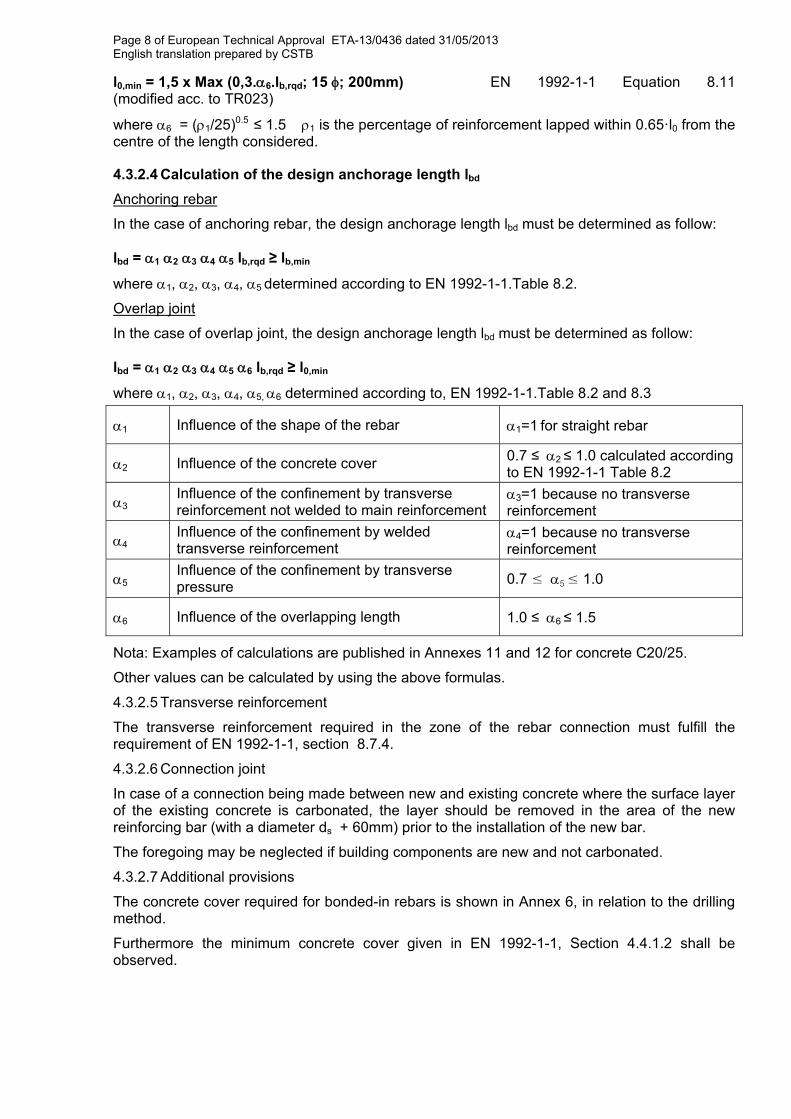
l0,min = 1,5 x Max (0,3.6.lb,rqd; 15 ; 200mm) EN 1992-1-1 Equation 8.11 (modified acc. to TR023)
where 6 = (1/25)0.5 ≤ 1.5 1 is the percentage of reinforcement lapped within 0.65·l0 from the centre of the length considered.
4.3.2.4 Calculation of the design anchorage length lbd
Anchoring rebar
In the case of anchoring rebar, the design anchorage length lbd must be determined as follow:
lbd = 1 2 3 4 5 lb,rqd ≥ lb,min
where 1, 2, 3, 4, 5 determined according to EN 1992-1-1.Table 8.2.
Overlap joint
In the case of overlap joint, the design anchorage length lbd must be determined as follow:
lbd = 1 2 3 4 5 6 lb,rqd ≥ l0,min
where 1, 2, 3, 4, 5, 6 determined according to, EN 1992-1-1.Table 8.2 and 8.3
1 Influence of the shape of the rebar 1=1 for straight rebar
2 Influence of the concrete cover 0.7 ≤2 ≤ 1.0 calculated according to EN 1992-1-1 Table 8.2
3 Influence of the confinement by transverse reinforcement not welded to main reinforcement
3=1 because no transverse reinforcement
4 Influence of the confinement by welded transverse reinforcement
4=1 because no transverse reinforcement
5 Influence of the confinement by transverse pressure 0.7 ≤5 ≤ 1.0
6 Influence of the overlapping length 1.0 ≤6 ≤ 1.5
Nota: Examples of calculations are published in Annexes 11 and 12 for concrete C20/25.
Other values can be calculated by using the above formulas.
4.3.2.5 Transverse reinforcement
The transverse reinforcement required in the zone of the rebar connection must fulfill the requirement of EN 1992-1-1, section 8.7.4.
4.3.2.6 Connection joint
In case of a connection being made between new and existing concrete where the surface layer of the existing concrete is carbonated, the layer should be removed in the area of the new reinforcing bar (with a diameter ds + 60mm) prior to the installation of the new bar.
The foregoing may be neglected if building components are new and not carbonated.
4.3.2.7 Additional provisions
The concrete cover required for bonded-in rebars is shown in Annex 6, in relation to the drilling method.
Furthermore the minimum concrete cover given in EN 1992-1-1, Section 4.4.1.2 shall be observed.
Page 9 of European Technical Approval ETA-13/0436 dated 31/05/2013 English translation prepared by CSTB
4.4 Installation
The fitness for use of the rebar connection can only be assumed if the rebar is installed as follows:
The installation of the post installed rebars shall be carried out according to the manufacturer’s installation instructions
The installation of post-installed rebars shall be done only by suitable trained installer and under supervision on site. The conditions under which an installer may be considered as suitable trained and the conditions for supervision on site are up to the Member States in which the installation is done.
Use of the system only as supplied by the manufacturer without exchanging the components of an system;
Checks before placing the rebar to ensure that the strength class of the concrete in which the rebar is to be placed is in the range;
The surface of the joint between new and existing concrete should be prepared (roughing, keying) according to the envisaged intended use according to EN 1992-1-1;
Check of concrete being well compacted, e.g. without significant voids;
Keeping the anchorage depth as specified in the design drawings;
Keeping of the concrete cover and spacing as specified in the design drawings;
The drilling and cleaning of the hole and the installation shall be performed only with the equipment as specified by the manufacturer given in annexes 5 to 9. It shall be ensured that this equipment is available on site and is used;
Positioning of the drill holes without damaging the reinforcement;
In case of aborted drill hole: the drill hole shall be filled with mortar;
The post installed rebar connection must not be installed in flooded holes;
Rebar installation ensuring the specified embedment depth, that is the appropriate depth marking of the rebar not exceeding the concrete surface;
4.5 Responsibility of the manufacturer
It is the manufacturer’s responsibility to ensure that the information on the specific conditions according to 1 and 2 including Annexes referred to in § 4.3. is given to those who are concerned. This information may be made by reproduction of the respective parts of the European Technical Approval. In addition all installation data shall be shown clearly on the package and/or on an enclosed instruction sheet, preferably using illustration(s).
The minimum data required are:
drill bit diameter,
rebar diameter,
admissible service temperature range,
curing time of the bonding material depending on the installation temperature,
information on the installation procedure, including cleaning of the hole, preferably by means of an illustration,
reference to any special installation equipment needed,
identification of the manufacturing batch.
All data shall be presented in a clear and explicit form.
Page 10 of European Technical Approval ETA-13/0436 dated 31/05/2013 English translation prepared by CSTB
5 Recommendations concerning packaging, transport and storage Each cartridge of resin is marked with the identifying mark of the producer, the trade name, the charge code, storage life, curing and processing time.
The cartridges of resin shall be protected against sun radiation and shall be stored according to the manufacturer’s installation instructions in dry conditions at temperatures of at least 0°C to not more than +35°C.
Mortar cartridges with expired shelf life must no longer be used.
The original French version is signed by
Le Directeur Technique C. BALOCHE
Page 11 of EEnglish trans
ProducThe poststraight dEurocode
Injection
Cartridge
Cartridge
Mixing noz
Reinforcin Covered athe design Installation Temperatu(maximum Overhead
SPIT MULT
Product de
European Techslation prepare
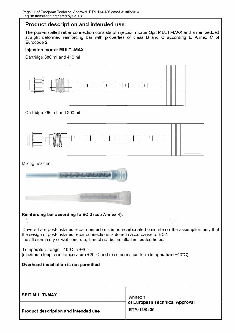
ct descri-installed redeformed re 2
n mortar MU
e 380 ml and
e 280 ml and
zles
ng bar acco
re post-instof post-inst
n in dry or w
ure range: -4long term t
installation
TI-MAX
escription
hnical Approvaed by CSTB
ption anebar connecreinforcing
ULTI-MAX
d 410 ml
d 300 ml
ording to E
talled rebar talled rebar
wet concrete
40°C to +40temperature
n is not pe
and intend
al ETA-13/04
nd intendction consisbar with p
C 2 (see A
connectionconnection
e, it must no
0°C e +20°C and
rmitted
ded use
36 dated 31/0
ded usests of injectproperties o
Annex 4):
ns in non-cans is done inot be installe
d maximum
05/2013
tion mortar of class B
arbonated cn accordanced in floode
m short term
Annex 1of Europea
ETA-13/04
Spit MULT and C ac
concrete once to EC2.
ed holes.
temperatur
an Technic
436
TI-MAX and ccording to
n the assum
re +40°C)
cal Approv
an embeddo Annex C
mption only t
al
ded C of
that
Page 12 of European Technical Approval ETA-13/0436 dated 31/05/2013 English translation prepared by CSTB
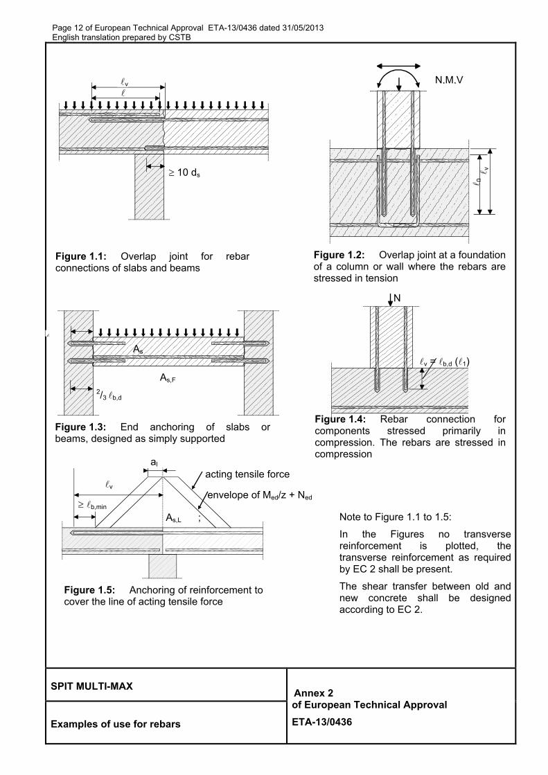
SPIT MULTI-MAX Annex 2 of European Technical Approval
ETA-13/0436 Examples of use for rebars
Figure 1.5: Anchoring of reinforcement tocover the line of acting tensile force
Figure 1.1: Overlap joint for rebarconnections of slabs and beams
Figure 1.2: Overlap joint at a foundationof a column or wall where the rebars arestressed in tension
v = b,d (1)
N
Figure 1.4: Rebar connection for components stressed primarily in compression. The rebars are stressed in compression
Figure 1.3: End anchoring of slabs orbeams, designed as simply supported
acting tensile force
b,min As,L ;
v
al
envelope of Med/z + Ned
Note to Figure 1.1 to 1.5:
In the Figures no transversereinforcement is plotted, thetransverse reinforcement as requiredby EC 2 shall be present.
The shear transfer between old andnew concrete shall be designedaccording to EC 2.
v
10 ds
2/3 b,d
As
As,F
N,M,V
0
v
Page 13 of European Technical Approval ETA-13/0436 dated 31/05/2013 English translation prepared by CSTB
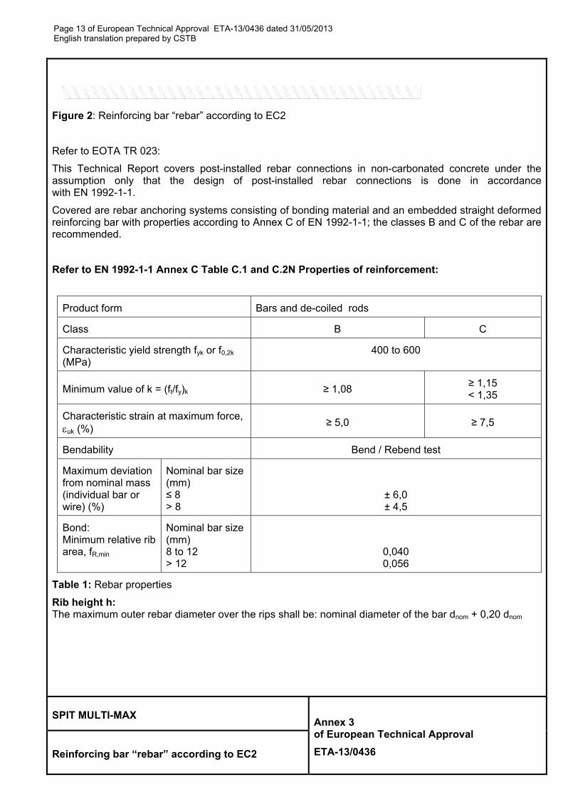
Figure 2: Reinforcing bar “rebar” according to EC2
Refer to EOTA TR 023:
This Technical Report covers post-installed rebar connections in non-carbonated concrete under the assumption only that the design of post-installed rebar connections is done in accordance with EN 1992-1-1.
Covered are rebar anchoring systems consisting of bonding material and an embedded straight deformed reinforcing bar with properties according to Annex C of EN 1992-1-1; the classes B and C of the rebar are recommended.
Refer to EN 1992-1-1 Annex C Table C.1 and C.2N Properties of reinforcement:
Product form Bars and de-coiled rods
Class B C
Characteristic yield strength fyk or f0,2k (MPa)
400 to 600
Minimum value of k = (ft/fy)k ≥ 1,08 ≥ 1,15 < 1,35
Characteristic strain at maximum force, uk (%)
≥ 5,0 ≥ 7,5
Bendability Bend / Rebend test
Maximum deviation from nominal mass (individual bar or wire) (%)
Nominal bar size (mm) ≤ 8 > 8
± 6,0 ± 4,5
Bond: Minimum relative rib area, fR,min
Nominal bar size (mm) 8 to 12 > 12
0,040 0,056
Table 1: Rebar properties
Rib height h: The maximum outer rebar diameter over the rips shall be: nominal diameter of the bar dnom + 0,20 dnom
SPIT MULTI-MAX Annex 3 of European Technical Approval
ETA-13/0436 Reinforcing bar “rebar” according to EC2
Page 14 of EEnglish trans
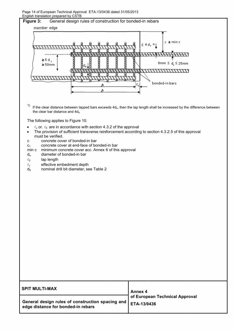
Figure 3:
1) If the c
the cle
The follo
v or. The
mustc cc1 cmin c mds d0 lav ed0 n
SPIT MULT
General dedge dista
European Techslation prepare
Genera
clear distance ear bar distanc
wing applies
. 0 are in acprovision of t be verified. concrete covconcrete covminimum condiameter of bap length effective embnominal drill
TI-MAX
design ruleance for bo
hnical Approvaed by CSTB al design rul
between lappce and 4ds.
s to Figure 10
ccordance wisufficient tra
ver of bondedver at end-facncrete cover bonded-in ba
bedment depbit diameter,
s of constonded-in re
al ETA-13/04
es of const
ped bars excee
0:
ith section 4.nsverse rein
d-in bar ce of bondedacc. Annex 6
ar
pth see Table 2
ruction spebars
36 dated 31/0
truction for b
eds 4ds, then
.3.2 of the apnforcement a
d-in bar 6 of this app
2
acing and
05/2013
bonded-in r
the lap length
pproval ccording to s
proval
Annex 4of Europ
ETA-13/0
rebars
h shall be incre
section 4.3.2
ean Techn
0436
eased by the d
2.5 of this app
nical Appro
difference betw
proval
oval
ween
Page 15 of European Technical Approval ETA-13/0436 dated 31/05/2013 English translation prepared by CSTB
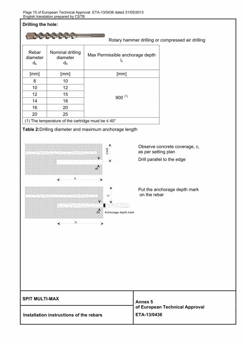
Drilling the hole:
Rotary hammer drilling or compressed air drilling
Rebar diameter
ds
Nominal drilling diameter
d0
Max Permissible anchorage depthlv
[mm] [mm] [mm]
8 10
900 (1)
10 12
12 15
14 18
16 20
20 25
(1) The temperature of the cartridge must be ≤ 40°
Table 2:Drilling diameter and maximum anchorage length
Observe concrete coverage, c, as per setting plan
Drill parallel to the edge
lv
d0
C
Anchorage depth mark
Put the anchorage depth mark on the rebar
SPIT MULTI-MAX Annex 5 of European Technical Approval
ETA-13/0436 Installation instructions of the rebars
lv
d0
Cd
rill
Page 16 of EEnglish trans
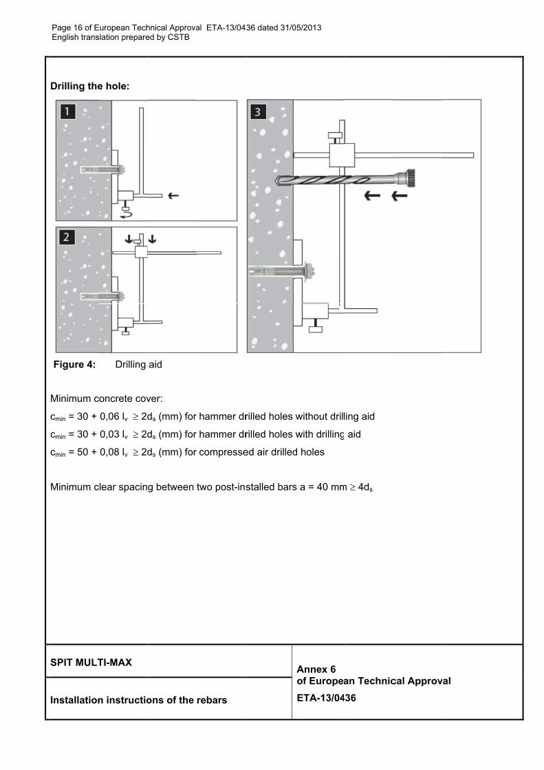
Drilling the
Figure 4:
Minimum c
cmin = 30 +
cmin = 30 +
cmin = 50 +
Minimum c
SPIT MULT
Installation
European Techslation prepare
e hole:
Drilling
concrete cov
0,06 lv 2d
0,03 lv 2d
0,08 lv 2d
clear spacin
TI-MAX
n instructio
hnical Approvaed by CSTB
aid
ver:
ds (mm) for
ds (mm) for
ds (mm) for
g between
ons of the
al ETA-13/04
hammer dr
hammer dr
compresse
two post-ins
rebars
36 dated 31/0
rilled holes
rilled holes
ed air drilled
stalled bars
05/2013
without dril
with drilling
d holes
s a = 40 mm
Annex 6 of Europea
ETA-13/04
ling aid
aid
m 4ds
an Technic
436
cal Approv
al
Page 17 of European Technical Approval ETA-13/0436 dated 31/05/2013 English translation prepared by CSTB
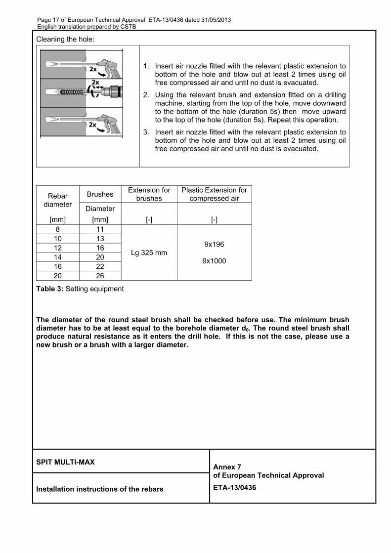
Cleaning the hole:
1. Insert air nozzle fitted with the relevant plastic extension to bottom of the hole and blow out at least 2 times using oil free compressed air and until no dust is evacuated.
2. Using the relevant brush and extension fitted on a drilling machine, starting from the top of the hole, move downward to the bottom of the hole (duration 5s) then move upward to the top of the hole (duration 5s). Repeat this operation.
3. Insert air nozzle fitted with the relevant plastic extension to bottom of the hole and blow out at least 2 times using oil free compressed air and until no dust is evacuated.
Rebar diameter
Brushes Extension for
brushes Plastic Extension for
compressed air
Diameter
[mm] [mm] [-] [-] 8 11
Lg 325 mm 9x196
9x1000
10 13 12 16 14 20 16 22 20 26
Table 3: Setting equipment
The diameter of the round steel brush shall be checked before use. The minimum brush diameter has to be at least equal to the borehole diameter d0. The round steel brush shall produce natural resistance as it enters the drill hole. If this is not the case, please use a new brush or a brush with a larger diameter.
SPIT MULTI-MAX Annex 7 of European Technical Approval
ETA-13/0436 Installation instructions of the rebars

Page 18 of EEnglish trans
Safety preThe safety
follow• Stora• Cartr• Base• Chec
Dispensin
Ø Drilling [mm]
10 to 20
SPIT MULT
Installation
Pis
European Techslation prepare
ecaution y data sheewed. age temperaridge tempee material teck the date o
g into the h
Plastic extext x l [mm]
9x196 9x1000
TI-MAX
n instructio
ston plug
hnical Approvaed by CSTB
et must be
ature of carerature at timemperature of expiry of
hole:
tension for
ons of the
Plastic e
al ETA-13/04
e red befor
tridge +0°Cme of installat time of inthe cartridg
1. Put
2. Che
3. Cutvolumuexteanc
4. ScrdispachInsethethe
mixing nozz
rebars
extension
36 dated 31/0
re using th
C to +35 °Clation: Mustnstallation: ge
t the ancho
eck the anc
t the pistoume of resst be indension. Thechorage dep
rew the mpense the fhieved for ert the noz
e resin, withe hole until t
zle Mixing
[-]
Stand
Ao
E
05/2013
e product
t be ≥ 0°C Must be be
rage depth
chorage dep
on plug at sin that neeicated on e marking mpth
mixing nozzfirst part to each new zle to the fadrawing thehe mark ap
g nozzle
dard mixing
Annex 8 of European
ETA-13/043
Nozzle
and the sa
tween -5°C
mark on the
pth
the relevaed to be inj
the mixinmust be plac
zle onto thwaste until cartridge o
ar end of the nozzle as
ppear.
[-]
nozzle
n Technica
6
afety instru
C and +40°C
e rebar
ant diametejected in th
ng nozzle ced at 0.5 t
he cartridg an even coor mixing he hole, ans the hole fi
Pi
[-]
al Approval
ctions mus
C
er. The he hole
or its ime the
ge and olour is nozzle. d inject lls. Fill
iston plug
]
l
st be
Page 19 of European Technical Approval ETA-13/0436 dated 31/05/2013 English translation prepared by CSTB
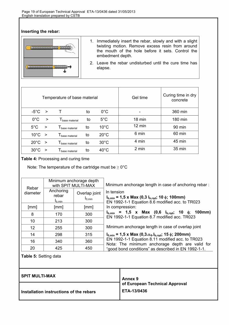
Inserting the rebar:
1. Immediately insert the rebar, slowly and with a slight twisting motion. Remove excess resin from around the mouth of the hole before it sets. Control the embedment depth.
2. Leave the rebar undisturbed until the cure time has elapse.
Temperature of base material Gel time Curing time in dry
concrete
-5°C > T to 0°C - 360 min
0°C > Tbase material to 5°C 18 min 180 min
5°C > Tbase material to 10°C 12 min 90 min
10°C > Tbase material to 20°C 6 min 60 min
20°C > Tbase material to 30°C 4 min 45 min
30°C > Tbase material to 40°C 2 min 35 min
Table 4: Processing and curing time
Note: The temperature of the cartridge must be ≥ 0°C
Rebar diameter
Minimum anchorage depth with SPIT MULTI-MAX Minimum anchorage length in case of anchoring rebar :
In tension lb,min = 1,5 x Max (0,3 lb,rqd; 10 ; 100mm) EN 1992-1-1 Equation 8.6 modified acc. to TR023 In compression: lb,min = 1,5 x Max (0,6 lb,rqd; 10 100mm)EN 1992-1-1 Equation 8.7 modified acc. TR023 Minimum anchorage length in case of overlap joint
l0,min = 1,5 x Max (0,3.6.lb,rqd; 15 ; 200mm) EN 1992-1-1 Equation 8.11 modified acc. to TR023 Nota: The minimum anchorage depth are valid for “good bond conditions” as described in EN 1992-1-1.
Anchoring rebar lb,min
Overlap jointl0,min
[mm] [mm] [mm]
8 170 300
10 213 300
12 255 300
14 298 315
16 340 360
20 425 450
Table 5: Setting data
SPIT MULTI-MAX Annex 9 of European Technical Approval
ETA-13/0436 Installation instructions of the rebars
Page 20 of European Technical Approval ETA-13/0436 dated 31/05/2013 English translation prepared by CSTB
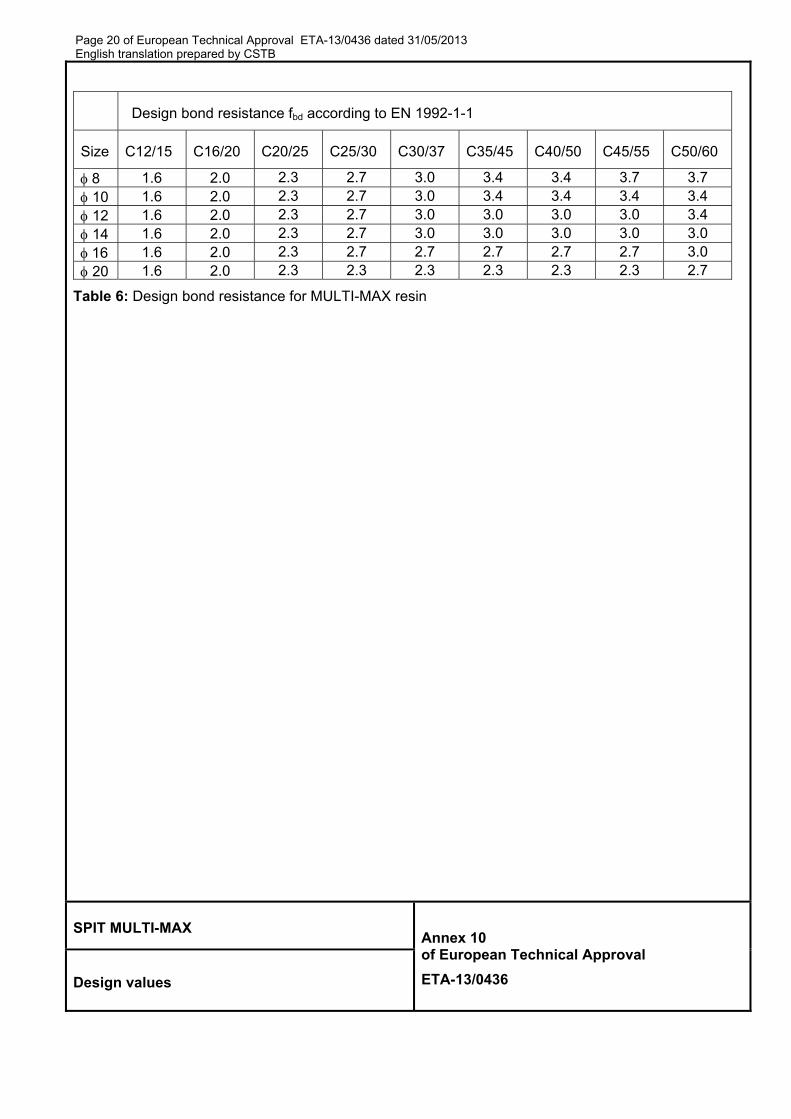
Design bond resistance fbd according to EN 1992-1-1
Size C12/15 C16/20 C20/25 C25/30 C30/37 C35/45 C40/50 C45/55 C50/60
8 1.6 2.0 2.3 2.7 3.0 3.4 3.4 3.7 3.7 10 1.6 2.0 2.3 2.7 3.0 3.4 3.4 3.4 3.4 12 1.6 2.0 2.3 2.7 3.0 3.0 3.0 3.0 3.4 14 1.6 2.0 2.3 2.7 3.0 3.0 3.0 3.0 3.0 16 1.6 2.0 2.3 2.7 2.7 2.7 2.7 2.7 3.0 20 1.6 2.0 2.3 2.3 2.3 2.3 2.3 2.3 2.7
Table 6: Design bond resistance for MULTI-MAX resin
SPIT MULTI-MAX Annex 10 of European Technical Approval
ETA-13/0436 Design values

Page 21 of European Technical Approval ETA-13/0436 dated 31/05/2013 English translation prepared by CSTB
MULTI-MAX – Anchoring of Rebar HA Fe E500 – C20/25 concrete (fbd=2.3Mpa)
=2=3=4=5=1.0or 5= 0.7 1=3=4=1.0
Rebar diameter
Anchorage depth
lbd
Max. design value Nrd
in the rebar
Volume of resin
Anchorage depth
Max. design value Nrd
in the rebar
Volume of resin
[mm] [mm] [kN] [ml] [mm] [kN] [ml]
8
170 * 9.83 6 170 * 14.05 6 220 12.72 7 190 15.69 6 270 15.61 9 210 17.34 7 320 18.50 11 240 19.82 8 378 21.85 13 265 21.85 9
10
213 * 15.37 9 213 * 21.95 9 270 19.51 11 240 24.77 10 340 24.57 14 270 27.87 11 400 28.90 17 300 30.97 12 473 34.15 20 331 34.15 14
12
255 * 22.13 19 255 * 31.61 19 330 28.61 25 290 35.92 22 410 35.55 31 320 39.64 24 480 41.62 37 360 44.59 27 567 49.17 43 397 49.17 30
14
298 * 30.12 36 298 * 43.03 36 380 38.44 46 330 47.69 40 470 47.54 57 380 54.92 46 570 57.66 69 420 60.70 51 662 66.93 80 463 66.93 56
16
340 * 39.34 46 340 * 56.20 46 440 50.87 60 380 62.76 52 540 62.43 73 430 71.02 58 650 75.15 88 480 79.28 65 756 87.42 103 529 87.42 72
20
425 * 61.47 90 425 * 87.81 90 540 78.04 115 480 99.09 102 660 95.38 140 540 111.48 115 780 112.72 165 600 123.87 127 900 130.06 191 662 136.59 140
1) Tabulated maximum tension loads are valid for good bond conditions according to EN 1992-1-1. For all other bond conditions the values for tension loads must be multiplied by 0.7.
2) The volume V of mortar can be estimated using the equation V = 1.2.(do²-d²).lbd/4
* Values corresponding to the minimum anchorage length lb,min
SPIT MULTI-MAX Annex 11 of European Technical Approval
ETA-13/0436 Design values
Page 22 of European Technical Approval ETA-13/0436 dated 31/05/2013 English translation prepared by CSTB
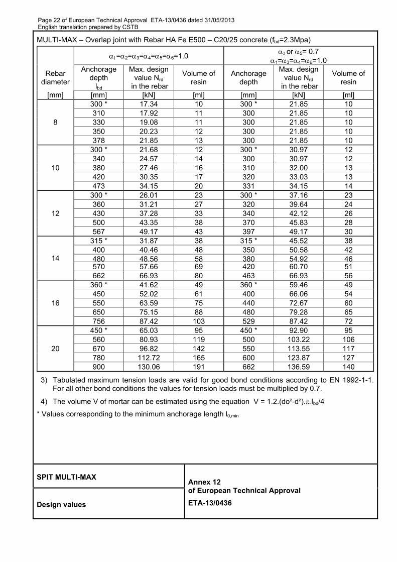
MULTI-MAX – Overlap joint with Rebar HA Fe E500 – C20/25 concrete (fbd=2.3Mpa)
=2=3=4=5=6=1.0or 5= 0.7
1=3=4=6=1.0
Rebar diameter
Anchorage depth
lbd
Max. design value Nrd
in the rebar
Volume of resin
Anchorage depth
Max. design value Nrd
in the rebar
Volume of resin
[mm] [mm] [kN] [ml] [mm] [kN] [ml]
8
300 * 17.34 10 300 * 21.85 10 310 17.92 11 300 21.85 10 330 19.08 11 300 21.85 10 350 20.23 12 300 21.85 10 378 21.85 13 300 21.85 10
10
300 * 21.68 12 300 * 30.97 12 340 24.57 14 300 30.97 12 380 27.46 16 310 32.00 13 420 30.35 17 320 33.03 13 473 34.15 20 331 34.15 14
12
300 * 26.01 23 300 * 37.16 23 360 31.21 27 320 39.64 24 430 37.28 33 340 42.12 26 500 43.35 38 370 45.83 28 567 49.17 43 397 49.17 30
14
315 * 31.87 38 315 * 45.52 38 400 40.46 48 350 50.58 42 480 48.56 58 380 54.92 46570 57.66 69 420 60.70 51 662 66.93 80 463 66.93 56
16
360 * 41.62 49 360 * 59.46 49 450 52.02 61 400 66.06 54 550 63.59 75 440 72.67 60 650 75.15 88 480 79.28 65 756 87.42 103 529 87.42 72
20
450 * 65.03 95 450 * 92.90 95 560 80.93 119 500 103.22 106 670 96.82 142 550 113.55 117 780 112.72 165 600 123.87 127 900 130.06 191 662 136.59 140
3) Tabulated maximum tension loads are valid for good bond conditions according to EN 1992-1-1. For all other bond conditions the values for tension loads must be multiplied by 0.7.
4) The volume V of mortar can be estimated using the equation V = 1.2.(do²-d²).lbd/4
* Values corresponding to the minimum anchorage length l0,min
SPIT MULTI-MAX Annex 12 of European Technical Approval
ETA-13/0436 Design values