ev / kv service manual blain valves en iso 9001 for ...6 blain hydraulics · pfa enstrasse 1 ·...
TRANSCRIPT

1BLAIN HYDRAULICS · Pfaff enstrasse 1 · D-74078 Heilbronn · Tel. +49 7131 28210 · Fax +49 7131 282199 · www.blain.de · [email protected]
EV / KV Service Manual
EN ISO 9001
BLAIN VALVES FOR HYDRAULIC ELEVATORSExcellence in Simplicity and Performance
www.bla in .dePfaff enstrasse 1 · 74078 Heilbronn · GermanyTel.: +49 7131 28210 · Fax: +49 7131 282199
SERVICEMANUAL

2BLAIN HYDRAULICS · Pfaffenstrasse 1 · D-74078 Heilbronn · Tel. +49 7131 28210 · Fax +49 7131 282199 · www.blain.de · [email protected]
EV / KV Service Manual
EN ISO 9001
Service Manual
GmbH
!Caution
Only qualified elevator mechanics are permitted to install and adjust elevator control valves and controllers.
Every Blain control valve is subjected to strong quality standards, from production, adjustment and testing, to final shipment.
This manual will provide assistance whenever servicing is required. If necessary, please contact our technical de-partment, stating the valve number, which is engraved into the EV casting above the nameplate, as well as other related technical data.
Blain Hydraulics GmbH Tel. +49 7131 28210Pfaffenstrasse 1 Fax +49 7131 28219974078 Heilbronn www.blain.deGermany [email protected]
Designer and Manufacturer of the highest quality control valves & safety componentsfor hydraulic elevators
Elevator Valve EV & KV
Page
3 Contacts at Blain
4 EV ¾" Cross Section Diagrams of Valve
5 EV 1½" - 2½" Cross Section Diagrams of Valve
6+7 Quick Adjustment Procedure
8 Switches, Slow Down Distances
9 EV Trouble Shooting, Up Travel
10 EV Trouble Shooting, Down Travel
11 EV System Leakage
12 EV Spare Parts List
13 Down Levelling Adj. 9, Replacement
14 KV Cross Section Diagrams of Valve
15 KV Trouble Shooting, Up Travel
16 KV Trouble Shooting, Down Travel
17 KV System Leakage
18 KV Spare Parts List
19 KS Slack Rope Valve Purpose and Adjustment
20 Overheating of Power Units
21-30 CAD Drawings
31 EV ¾" O-ring template
32 EV 1½"-2" O-ring template
33 L10 ¾" O-ring template
34 HP O-ring template
35 Flow-Pressure-Tables (metric)
36 Flow-Pressure-Tables (USA)
Content

3BLAIN HYDRAULICS · Pfaffenstrasse 1 · D-74078 Heilbronn · Tel. +49 7131 28210 · Fax +49 7131 282199 · www.blain.de · [email protected]
EV / KV Service Manual
EN ISO 9001Contacts at Blain

4BLAIN HYDRAULICS · Pfaffenstrasse 1 · D-74078 Heilbronn · Tel. +49 7131 28210 · Fax +49 7131 282199 · www.blain.de · [email protected]
EV / KV Service Manual
EN ISO 9001
SteuerelementeA Magnetventil (Halt oben)B Magnetventil (Abbremsen auf)C Magnetventil (Abbremsen unten)D Magnetventil (Halt unten)H NotablassventilS ÜberdruckventilU UmlaufkolbenV RückschlagventilW Schleichfahrtventil (auf)X SenkkolbenY Schleichfahrtventil (ab)
Einstellungen AUF1 Umlaufeinstellung2 Anfahrdrossel3 Abbremsdrossel4 Schleichfahrteinstellung5 Haltedrossel
Einstellungen AB6 Anfahrtdrossel7 Senkfahrteinstellung8 Abbremsdrossel9 Schleichfahrteinstellung
DruckPumpeUmlaufkolben Schleichfahrt (Auf)TankZylinderSenkkolbenSchleichfahrt (Ab)
Elevator Valve - EV 100 3/4’’for Home Lifts
7
W
U
Y
X
1
2
P
8
9 4
V
T
Z
6 3
HS
5
A
BC
D
5
2
S
3
H
8
6
A
BC
D
Elementos de mandoA Válv. magnética ‘parada’ (arriba)B Válv. magnética ‘frenado’ (subida)C Válv. magnética ‘frenado’ (bajada)D Válv. magnética ‘parada’ (abajo)H Válv. parada de urgencia (manual)S Válv. de seguridad U Válv. de desviaciónV Válv. de retenciónW Válv. de subida lentísimaX Válv. de bajada Y Válv. de bajada lentísima
Ajustes SUBIDA1 Desviación2 Arranque3 Frenado4 Recorrido lentísimo5 Parada
Ajustes BAJADA6 Arranque 7 Recorrido en bajada8 Frenado 9 Recorrido lentísimo
PresiónBombaVálvula de desviaciónSubida lentísimaTanqueCylindroVálvula de bajadaBajada lentísima
VerticalSection
HorizontalSections
P Pump PortT Tank PortZ Cylinder Port
Control ElementsA Solenoid (UP Stop)B Solenoid (UP Deceleration)C Solenoid (Down Deceleration)D Solenoid (Down Stop)H Manual LoweringS Relief ValveU By Pass ValveV Check ValveW Leveling Valve (Up)X Full Speed Valve (Down)Y Leveling Valve (Down)
Adjustments UP1 By Pass2 Up Acceleration3 Up Deceleration4 Up Leveling Speed5 Up Stop
Adjustments DOWN6 Down Acceleration7 Down Full Speed8 Down Deceleration9 Down Leveling Speed
Eléments de commandeA Electro-vanne ‘arrêt’ (en fin de montée)B Electro-vanne ‘ralentissement’ (montée)C Electro-vanne ‘ralentissement’ (descente)D Electro-vanne ‘arrêt’ (en fin de descente)H Descente de secour (homme mort)S Valve de sécurité U By-passV Clapet anti-retourW Soupape montée petite vitesseX Soupape descente Y Soupape descente petite vitesse
Réglages MONTÉE1 By-pass2 Etrangleur de démarrage3 Etrangleur de ralentissement4 Réglage de petite vitesse5 Etrangleur d’arrêt
Réglages DESCENTE6 Etrangleur de démarrage7 Réglage de grande vitesse8 Etrangleur de ralentissement 9 Réglage de petite vitesse
PressionPompeBy-passMontée petit vitesseCuveVérinSoupape descenteDescente petite vitesse
PressurePumpeBypass ValveUp LevelingTankCylinderDown ValveDown Leveling
C
DA
B

5BLAIN HYDRAULICS · Pfaffenstrasse 1 · D-74078 Heilbronn · Tel. +49 7131 28210 · Fax +49 7131 282199 · www.blain.de · [email protected]
EV / KV Service Manual
EN ISO 9001
7
W
U
Y
X
1
2
P
8
9 4
V
T
Z
6 3
HS
5
ABCD
52S3
H86
ABCD
SteuerelementeA Magnetventil (Halt oben)B Magnetventil (Abbremsen auf)C Magnetventil (Abbremsen unten)D Magnetventil (Halt unten)H NotablassventilS ÜberdruckventilU UmlaufkolbenV RückschlagventilW Schleichfahrtventil (auf)X SenkkolbenY Schleichfahrtventil (ab)
Einstellungen AUF1 Umlaufeinstellung2 Anfahrdrossel3 Abbremsdrossel4 Schleichfahrteinstellung5 Haltedrossel
Einstellungen AB6 Anfahrtdrossel7 Senkfahrteinstellung8 Abbremsdrossel9 Schleichfahrteinstellung
DruckPumpeUmlaufkolben Schleichfahrt (Auf)TankZylinderSenkkolbenSchleichfahrt (Ab)
PressionPompeBy-passMontée petit vitesseCuveVérinSoupape descenteDescente petite vitesse
Elevator ValveEV 100 1½’’, 2’’, 2½’’
Control ElementsA Solenoid (UP Stop)B Solenoid (UP Deceleration)C Solenoid (Down Deceleration)D Solenoid (Down Stop)H Manual LoweringS Relief ValveU By Pass ValveV Check ValveW Leveling Valve (Up)X Full Speed Valve (Down)Y Leveling Valve (Down)
Adjustments UP1 By Pass2 Up Acceleration3 Up Deceleration4 Up Leveling Speed5 Up Stop
Adjustments DOWN6 Down Acceleration7 Down Full Speed8 Down Deceleration9 Down Leveling Speed
PressurePumpeBypass ValveUp LevelingTankCylinderDown ValveDown Leveling
Eléments de commandeA Electro-vanne ‘arrêt’ (en fin de montée)B Electro-vanne ‘ralentissement’ (montée)C Electro-vanne ‘ralentissement’ (descente)D Electro-vanne ‘arrêt’ (en fin de descente)H Descente de secour (homme mort)S Valve de sécurité U By-passV Clapet anti-retourW Soupape montée petite vitesseX Soupape descente Y Soupape descente petite vitesse
Réglages MONTÉE1 By-pass2 Etrangleur de démarrage3 Etrangleur de ralentissement4 Réglage de petite vitesse5 Etrangleur d’arrêt
Réglages DESCENTE6 Etrangleur de démarrage7 Réglage de grande vitesse8 Etrangleur de ralentissement 9 Réglage de petite vitesse
PresiónBombaVálvula de desviaciónSubida lentísimaTanqueCylindroVálvula de bajadaBajada lentísima
Elementos de mandoA Válv. magnética ‘parada’ (arriba)B Válv. magnética ‘frenado’ (subida)C Válv. magnética ‘frenado’ (bajada)D Válv. magnética ‘parada’ (abajo)H Válv. parada de urgencia (manual)S Válv. de seguridad U Válv. de desviaciónV Válv. de retenciónW Válv. de subida lentísimaX Válv. de bajada Y Válv. de bajada lentísima
Ajustes SUBIDA1 Desviación2 Arranque3 Frenado4 Recorrido lentísimo5 Parada
Ajustes BAJADA6 Arranque 7 Recorrido en bajada8 Frenado 9 Recorrido lentísimo
HorizontalSections
P Pump PortT Tank PortZ Cylinder Port
VerticalSection
D C B A

6BLAIN HYDRAULICS · Pfaffenstrasse 1 · D-74078 Heilbronn · Tel. +49 7131 28210 · Fax +49 7131 282199 · www.blain.de · [email protected]
EV / KV Service Manual
EN ISO 9001Quick adjustment
procedure Solenoid CoilsDuring adjustment of the EV 100 valve, instead of making a full floor to floor travel to check operation, much time can be saved by removing the securing nuts of the coil and switching to deceleration or to acceleration by lifting or replacing the appropriate coil by hand, allowing several adjustment corrections during one car travel between floors.
Caution: Once removed from the solenoid tube, the energised coil will begin to overheat after about 10 s. If necessary, to slow the rate of heating, place an 14 or 17 mm socket key or similar steel rod as core thru the coil.Do not lay an energised coil to one side, otherwise it may overheat unnoticed.If the coil becomes too hot to hold, it must be replaced, back over the solenoid tube and any further adjustment carried out with the elevator making normal floor to floor runs.
Car not visible from MachineroomIf the car cannot be seen during adjustment of the valve, the acceleration and deceleration times can be heard from the change of the turbulent noise within the valve as the speed of the car changes. With no load in the car, the duration of the speed changes should be about 2.5 seconds. This applies to adjustments 2, 3, 6 and 8.
Up Travel (empty car)
1. Pilot Pressure SettingDisconnect coil A. Energise Motor (pump).If the car does not move, turn No. 1 ‘in’ until the car begins to move, turn No. 1 ‘out’ until the car stops, then back out again ½ turn. The car remains standing still.DO NOT UP-LEVEL WITH THIS ADJUSTMENT! Between full and empty car, levelling speed differences would be extreme.
2. Up AccelerationReconnect coil A. Start Motor and energise coil A and B (normal ‘up’ call).Observe the up acceleration. If it is too quick, turn No. 2 ‘in’ ½ turn. If it is too long, turn No. 2 ‘out’ ½ turn. Repeat until acceleration is satisfactory. Acceleration time should be about 2.5 s.
3. Up DecelerationWith coil B still disconnected. Energise motor and coil A (normal ‘up-level’ call).The car will travel upwards at levelling speed. Turn No. 3 ‘in’ until the car starts to up level faster, then turn No. 3 ‘out’ until the original levelling speed is observed. Reconnect coil B and place a normal up call.Observe the deceleration of the car. If it is too long, turn No. 3 ‘out’ ¼ turn; if it is too short, turn No. 3 ‘in’ ¼ turn. Repeat until deceleration is satisfactory. Deceleration time should be about 2.5 s.
Z1Z1
68
7
9 4
1
3
25
S
D C A BD C AB
1
2
5
S
9 4 3
68
7
PRE-SETTINGS EV 100 ¾“ EV 100 1½“ - EV 100 2½“
Adjustment No. 1 level with flange face 5 mm Socket key Adjustment No. 2 all the way ‘in’ then 1.5 turns ‘out’ then 2 turns ‘out’ 3 mm Socket key Adjustment No. 3 all the way ‘in’ then 1.5 turns ‘out’ then 2.5 turns ‘out’ 3 mm Socket key Adjustment No. 4 level with flange face 5 mm Socket key Adjustment No. 5 all the way ‘in’ then 1.5 turns ‘out’ then 2.5 turns ‘out’ 3 mm Socket key Adjustment No. S all the way ‘in’ then 1.5 turns ‘out’ then 1.5 turns ‘out’ 3 mm Socket key

7BLAIN HYDRAULICS · Pfaffenstrasse 1 · D-74078 Heilbronn · Tel. +49 7131 28210 · Fax +49 7131 282199 · www.blain.de · [email protected]
EV / KV Service Manual
EN ISO 9001Quick adjustment
procedure4. Up LevellingDisconnect coil B. Energise Motor and coil A (normal ‘up-level’ call).With adjustment No. 4 level with the face of the flange the car will up level. If the levelling speed is too fast, turn No. 4 ‘in’ until the speed is as required. If the speed is too slow, turn No. 4 ‘out’. Recommended speed 6 cm/s.
5. Up Soft StopDisconnect coil A. Energise Motor.The car should not move. Turn No. 5 ‘in’ until the car starts upwards then turn No. 5 ‘out’ until the car stops.Reconnect coil A. Energise Pump-Motor and A. The car will travel upwards at levelling speed. Lift A coil by hand briefly and observe the stopping of the car. If the stop is too hard turn No. 5 ‘in’ ¼ turn. If the stop is too soft, turn No. 5 ‘out’, ¼ turn. Repeat until the stop is satisfactory.
S Pressure Relief ValveTurn S screw ‘out’ until about 2 mm of the screw head is showing. Close the ball valve in the cylinder line and open the manual lowering H to lower valve pressure down to zero. Place an up call, energising motor and coils A and B. The relief pressure will show on the pressure gauge.To increase the relief valve setting, turn S ‘in’. To decrease the relief valve setting, turn S ‘out’, then open the manual lowering for ½ second with the pump still running to release locked-in pressure, before observing the pressure gauge reading.
7. Down Full SpeedPlace down call (coils C and D energised).Observe full down speed. Turn No. 7 ‘in’ for slower, ‘out’ for faster speed.
8. Down DecelerationPlace down call (coils C and D energised). As the car approaches full speed, remove coil D by hand briefly from the solenoid and observe the deceleration of the car.If the deceleration is too long, turn No. 8 ‘out’ ¼ turn; if it is too short, turn No. 8 ‘in’ ¼ turn.Caution. Never close adjustment & completely(in). This will cause damage to the car. Repeat until deceleration is satisfactory. Deceleration time should be about 2.5 secs.
9. Down Levelling SpeedDisconnect coil C. Place down call (D energised).Observe down levelling speed. Turn No. 9 ‘in’ for slower, ‘out’ for a fast down levelling speed.Recommended speed 6 cm/s.Note: The manually operated down speed is 6cm/s.
6. Down AccelerationTurn No. 6 all the way ‘in’. Place down call (coils C and D energised). The car will not move. Turn No. 6 ‘out’ slowly until the car accelerates downwards. If the acceleration is too long, turn No. 6 ‘out’ ¼ turn. If it is too short, turn No. 6 ‘in’ ¼ turn.Acceleration time should be about 2.5 s.
H Emergency LoweringThe manually operated emergency down speed and the D coil operated down levelling speed are the same.
Down StopWhen solenoid D is de-energised with solenoid C remaining de-energised, the car will stop according to the setting of adjustment 8 and no further adjustment will be required.
KS Slack Rope ValveThe KS is adjusted with a 3 mm Socket Key by turning the screw K ‘in’ for higher pressure and ‘out’ for lower pressure. With K turned all the way ‘in’, then half a turn back out, the unloaded car should descend when the D solenoid alone is energised. Should the car not descend, K must be backed off until the car just begins to descend, then backed off a further half turn to ensure that with cold oil, the car can be lowered as required.
PRE-SETTINGS EV 100 ¾“ EV 100 1½“ - EV 100 2½“
Adjustment No. 7 3 mm under the flange face 5 mm Socket key Adjustment No. 8 all the way ‘in’ then 1 turns ‘out’ then 1.5 turns ‘out’ 3 mm Socket key Adjustment No. 9 level with flange face 5 mm Socket key Adjustment No. 6 all the way ‘in’ then 1.5 turns ‘out’ then 1.5 turns ‘out’ 3 mm Socket key

8BLAIN HYDRAULICS · Pfaffenstrasse 1 · D-74078 Heilbronn · Tel. +49 7131 28210 · Fax +49 7131 282199 · www.blain.de · [email protected]
EV / KV Service Manual
EN ISO 9001
Recommended distances between leveling and stop switches
Accurate landing can be affected by different factors as follows:
a. If the levelling speed is fast i.e. 0,1 m/sec (20 ft/min), landing will not be as accurate as when the levelling speed is slower i.e. 0,05 m/sec (10 ft/min).
b. If the soft stop adjustment ‘5’ is set too soft, stopping will be less accurate as when ‘5’ is set for a quicker stop.
c. Particularly when the mechanic can not see the operation of the elevator car, it is possible that the elevator has not finished decelerating from fast speed before reaching the floor. In other words, the elevator has not slowed down to its correct levelling speed before the stop switch is actuated.
Usually, the levelling operation can be observed through the crack in the car doors. Alternatively, in the machine room, the turbulent noise within the valve during levelling can be heard and should last 1 to 2 secs. following 2 to 2,5 secs. deceleration time with no load in the car.
d. A difference in landing accuracy between the elevator being loaded and unloaded, can be due to the car under load, leaning to one side by several millimeters causing an alteration in the operating position of the stop switch by some centimetres.
Switch Distances
mtrs/sec.
0,10 5 2
0,15 10 4
0,20 15 6
0,25 18 7
0,30 25 9
0,35 30 12
0,40 40 16
0,45 46 18
0,50 50 20
0,55 58 23
0,60 70 28
0,70 80 31
0,80 95 36
0,90 105 41
1,00 120 48
With no load in the car, the deceleration time should be 2 to 2.5 secs. from full speed to levelling speed. The levelling time should be 1 to 2 secs.
Elevator Speed
Elevator Speed
Switch Distance
Switch Distance
20
30
40
50
60
70
80
90
100
110
120
140
160
180
200
approx. cm
approx. inchesft/min.

9BLAIN HYDRAULICS · Pfaffenstrasse 1 · D-74078 Heilbronn · Tel. +49 7131 28210 · Fax +49 7131 282199 · www.blain.de · [email protected]
EV / KV Service Manual
EN ISO 9001
EV 100 Trouble Shooting (2018)UP Travel
Up-Start too hard
Test: Turn adjustment 5 all the way in. If the elevator now starts upwards the problem is at solenoid A.
Solenoid A: not energised or voltage too low.
Solenoid A: tube not screwed down tight.
Solenoid A: Dirt or damage between needle AN and seat AS.
Adjustment 2 not far enough open.
Adjustment 1 too far back (open). Not enough pilot pressure.
Pressure relief valve S is set too low.
Adjustment 8 turned in too far (car sits on the buffer).
Bypass flow guide U is too large.
Pump running in the wrong direction.
The pump connection flange is leaking excessively.
The pump is undersize, worn or crack in the housing.Test: If by turning adjustment 1 with the pump running the pressure does not rise above 5 bar, even with a smaller bypass valve inserted, the problem should be sought at the pump.
Test: Turn adjustment 3 all the way in. If the elevator now travels upwards at full speed the problem is at solenoid B.
Solenoid B not energised or voltage too low.
Solenoid B tube not screwed down tight.
Solenoid B: Dirt or damage between needle AN and seat AS.
The pump connection flange is leaking excessively.
The pump is undersize or worn.
Adjustment 1 turned in too far.
Adjustment 2 turned out too far.
O-Ring UO on Bypass Valve U is leaking.
Star to Delta motor switch period is too long.
Excessive friction on the guide rails or in the cylinder head.
Solenoid B does not de-energise.
Adjustment 3 turned in too far.
O-Ring UO on Bypass Valve U is leaking.
Solenoid A is de-energised too late.
Adjustment 5 turned in too far.
Adjustment 1 turned in too far.
Up levelling speed too high.
Solenoid A and B reversed.
Up levelling speed too slow.
Middle O-Ring FO of flange 4F is leaking.
See A below.
Tighten Solenoid A tube.
Clean or change needle and seat.
Turn out adjustment 2.
Turn in adjustment 1 with the pump running.
Set relief valve higher. (turn in)
Turn out adjustment 8. Insert smaller bypass flow guide (see flow guide chartsat EV catalogue). Check motor direction and install the pump correctly.
Seal the pump connection.
Select bigger pump or replace pump.
See A below.
Tighten Solenoid B tube.
Clean or change needle and seat.
Seal the pump connection.
Select bigger pump or replace pump.
Turn out adjustment 1.
Turn in adjustment 2.
Change O-Ring → see EV Spare Parts List.
0.2-0.3 sec. is sufficient.
Can not be eliminated thru valve adjustment. Lift coil to check magnetic pull. See A below. Slow down switch possibly set to high (late).
Turn out adjustment 3. Turn in adjustment 2.
Change O-Ring → see EV Spare Parts List.
Turn out adjustment 5.
Turn out adjustment 1.
Turn in adjustment 4 to about 0.05 m/s levelling speed.
Turn out adjustment 4.
Change O-Ring → see EV Spare Parts List.
No Up-Start(Elevator remainsat floor)
Up-Start, butno Full Speed
No deceleration into levelling speed
Deceleration into levelling speed but overtravel of floor level
Elevator stops before reaching the floor(no levelling)
Bypass-pressurenot adjustable Change to flow guide with wider slots.
Restriction on the return line.
Bypass flow guide U too small (slots too narrow).
Levelling too fast Adjustment 4 too far screwed out. Turn in adjustment 4 to about 0.05 m/s levelling speed.
Swap solenoid A and B. See A below.
Bypass flow guide U too small (slots too narrow). Change to flow guide with wider slots.
Remove restriction; enlarge return line.
For checking the operation of the solenoids, remove the top nuts. By lifting the coils a few millimetres, the magnetic pull of the coil can be felt. For testing, the operation of the elevator car can also be controlled by lifting and replacing the coil.
Valves are already adjusted and tested. Check electrical operation before changing valve settings. Test that the correct solenoid is energised, by removing nut and raising solenoid slightly to feel pull.
Lift coil to check pull. See A below.Switch position in the shaft.
If the coil gets too hot, the coil has to be mounted onto the solenoid and the following adjustments have to be carried out on normal travels from floor to floor.Standard settings: Adjustments 1 approx. level with flange face. Adjustment 4 1mm above flange face (chamfer of adjustment screw is visible). Up to two turns in either direction may then be necessary. Adjustments 2, 3 & 5 all the way in (clockwise) then for EV ¾": adjustments 2 & 3 1.75 turns out (c-clockwise) and adjustment 51.25 turns out (c-clockwise), for EV 1 ½" – 2 ½": adjustments 3 & 5 two and half turns out (c-clockwise), adjustment 2 two turns out. Small final adjustments may be necessary.
Possible cause Recommended Problem
A

10BLAIN HYDRAULICS · Pfaffenstrasse 1 · D-74078 Heilbronn · Tel. +49 7131 28210 · Fax +49 7131 282199 · www.blain.de · [email protected]
EV / KV Service Manual
EN ISO 9001
EV 100 Trouble Shooting (2018)DOWN Travel
Solenoid D not energised or voltage too low.
Adjustment 6 turned in too far.
Adjustment 8 turned out too far.
O-Ring UO on Down Valve X is leaking.
Solenoid C not energised or voltage too low.
Adjustment 7 turned in too far.
Down Valve flow guide X too small.
Solenoid C and D reversed.
Adjustment 9 turned in too far. Spring 9F in adjustment 9 is broken or down levelling valve Y is blocked.
Adjustment 8 turned in too far. Filter of adjustment 8blocked or adjustment 8 is damaged.
Adjustment 9 turned out too far.
Solenoid valve C contaminated
Inner O-Ring FO on flange 7F is leaking.
Solenoid D tube not screwed down tight.
Adjustment 8 turned in too far.
Solenoid D contaminated or damaged.
O-Ring XO of Down Valve X is leaking.
O-Ring VO of Check Valve V is leaking.
O-Ring WO of Check Valve V is leaking.
Inner O-Ring FO on flange 4F is leaking.
O-Ring HO of Manual Lowering H is leaking.
HP: Handpump is leaking.
HX/MX: Adjustment 8M turned in too far. HX/MX: Down valve 9M is leaking.Dirt or damage between the needle DN and seat DS.
HX/MX: O-Ring XO of Down Valve YM is leaking.
HX/MX: Manual Lowering is leaking (HX/MX). Contraction of oil during cooling especially from 35°Cor above.
No full speed
No decellerationinto levellingspeed. Elevator travels though floor level
Elevator sinksslowly due toinner leakage(Relevelling)
Lift coil to check magnetic pull. See A below.
Turn out adjustment 6.
Turn in adjustment 8 cautiously.Attention: Danger of travelling through.
Change O-Ring → see EV Spare Parts List.
Lift coil to check magnetic pull. See A below.
Turn out adjustment 7.
Check insert size (see flow guide charts page 6)
Lift coil to check magnetic pull. See A below.
Turn out adjustment 9 to about 0.05 m/s levelling speed. Replace the spring orclean the down levelling valve.
Turn out adjustment 8 about ½ turn, clean the filter orreplace adjustment 8 .
Turn in adjustment 9 to about 0.05 m/s levelling speed.
Clean or change needle and seat.
Change O-Ring → see EV Spare Parts List.
Tighten Solenoid D tube.
Turn out adjustment 8 about ½ turn.
Clean solenoid D or replace neddle DN and seat DS. Change O-Ring → see EV Spare Parts List.When Down Valve is compensated, replace Down Valve.
Change Check Valve → see EV Spare Parts List.
Change O-Ring → see EV Spare Parts List.
Change O-Ring → see EV Spare Parts List.
Replace Manual Lowering.
Seal the hand pump.
Turn out adjustment 8M.
Clean or change needle and seat.
Change O-Ring → see EV Spare Parts List.
Replace Manual Lowering.
Consider oil cooler if hot oil is a problem.
Elevator sinksdue toinner leakageof auxiliary equipment
Damage on down valve X or check valve V. Check parts and change them if necessary.
No downlevelling. Elevator stops before floor level
For checking the operation of the solenoids, remove the top nuts. By lifting the coils a few millimetres, the magnetic pull of the coil can be felt. For testing, the operation of the elevator car can also be controlled by lifting and replacing the coil.
Valves are already adjusted and tested. Check electrical operation before changing valve settings. Test that the correct solenoid is energised, by removing nut and raising solenoid slightly to feel pull.
If the coil gets too hot, the coil has to be mounted onto the solenoid and the following adjustments have to be carried out on normal travels from floor to floor.Standard settings: Adjustments 7 & 9 approx. level with flange faces. Up to two turns in either direction may then be necessary. Adjustments 6 & 8 all the way in (clockwise) then for EV ¾", adjustment 8 one turn and adjustment 6 two turns out (c-clockwise), for EV 1 ½" – 2 ½", adjustment 8 1.5 turns and adjustment 6 2.5 turns out (c-clockwise). Small final adjustments may be necessary.
A
For possible down leakage points,see technical documentation ‟System Leakage“.
Replace one seal at a time and test before proceeding tothe next point of possible leakage, if still necessary.
Pressure setting of KS too high. Turn adjustment KS out.
Micro Drive MD, Door Lock Valve L10 orL20 are leaking. When possible isolate and check.
No Down Start
Elevator sinksquickly
Possible cause Recommended Problem
Filter on solenoid D contaminated. Clean filter.

11BLAIN HYDRAULICS · Pfaffenstrasse 1 · D-74078 Heilbronn · Tel. +49 7131 28210 · Fax +49 7131 282199 · www.blain.de · [email protected]
EV / KV Service Manual
EN ISO 9001
EV System Leakage(re-levelling)

12BLAIN HYDRAULICS · Pfaffenstrasse 1 · D-74078 Heilbronn · Tel. +49 7131 28210 · Fax +49 7131 282199 · www.blain.de · [email protected]
EV / KV Service Manual
EN ISO 9001EV
apr 16
GmbH
Blain Hydraulics GmbH Tel. +49 7131 28210Pfaff enstrasse 1 Fax +49 7131 28219974078 Heilbronn www.blain.deGermany [email protected]
1
UF
MM
M
DR
MO
DF
DN
DK
DG
DS
MMAD
AR
M
MO
AN
AS
AH
AF
FS
FS
Y
XXD
UD UOU 1E EO FO1F
W6 VF FO 4F FS 4E EO
FO 7F
9F
7O7EF UOXO EO9E
KS
97
4
C+D A+B
FD
VO WO W
3+5+6
2
S
H
8
SMMS SESF SZ SO
HO
SK
V
D C A B
5
12
68 3 9 7
D C AB
H SH S 5
1
2
49 7
468
3
D C AB
5
1
2
4
3
H S
9 7
68
O-ring: V=FKM-Viton P=NBR-Perbunan
Pos. No. Item FS Lock Screw - Flange FO O-Ring - Flange 1F Flange - By Pass EO 0-Ring - Adjustment 1E Adjustment - By Pass UO 0-Ring - By Pass Valve U By Pass Valve UD Noise Suppressor UF Spring - By Pass 2 Adjustment - Up Acceleration 3 Adjustment - Up Deceleration EO 0-Ring - Adjustment 4E Adjustment - Up Levelling 4F Flange - Check Valve FO 0-Ring - Flange VF Spring - Check Valve W Up-Levelling Valve WO 0-Ring - Up Levelling Valve VO Seal - Check Valve V Check Valve W6 Screw - Check Valve 3 Adjustment - Up Stop 3 Adjustment - Down Acceleration 7F Flange - Down Valve FO 0-Ring - Flange 7O 0-Ring - Adjustment 7E Adjustment - Down Valve UO 0-Ring - Down Valve XO Seal - Down Valve X Down Valve XD Noise Suppressor F Main Filter 8 Adjustment - Down Deceleration 9E Adjustment - Down Levelling EO 0-Ring - Adjustment 9F Spring - Down Valve Y Down Levelling Valve H Manual Lowering - Self Closing HO Seal - Manual Lowering SE Adjustment - Screw SM Hexagonal MS Grub Screw SO 0-Ring - Nipple SZ Nipple SF Spring SK Piston MM Nut - Solenoid AD Collar - Solenoid M Coil - Solenoid (indicate voltage) AR Tube - Solenoid 'Up' MO 0-Ring - Solenoid AN Needle - 'Up' AF Spring - Solenoid 'Up' AH Seat Housing - 'Up' AS Seat - Solenoid Up' MM Nut - Solenoid M Coil - Solenoid (indicate voltage) DR Tube - Solenoid 'Down' MO 0-Ring - Solenoid DF Spring - Solenoid 'Down' DN Needle - 'Down' DK Core - Solenoid DG Seat Housing with Screen-'Down' FD Filter Solenoid DS Seat - Solenoid 'Down'Some parts occur more than once in different positions of the valve.
EV Spare Parts List
Adjustments
In case of down leakage, replace and test in the following order: DS & DN , XO , VO , WO , FO + HO .
Flow Valves
F Do not remove!
Solenoid Valves
Taper threads: Do not exceed 8 turns of piping into the valve connections.
1
7
S
4
56
3
8
9
H
A+B
C+D
2
O-Ring-SizeNo. ¾" 1 ½" 2 ½"
FO 26x2P 47x2.5P 58x3P *EO 9x2P 9x2P 9x2PUO 26x2V 39.34x2.62V 58x3VWO 5.28x1.78V 5.28x1.78V 5.28x1.78VVO 23x2,5V 42x3V 60x3V **7O 5.28x1.78P 9x2P 9x2PXO 13x2V 30x3V 47x3VHO 5.28x1.78V 5.28x1.78V 5.28x1.78VSO 5.28x1.78P 5.28x1.78P 5.28x1.78PMO 26x2P 26x2P 26x2P
* FO by 4F 2½" is 67x2.5P** 90 Shore
To order EV: Size (inch), valve type, state pump fl ow, empty car pressure (or fl ow guide size) and solenoid voltage.Example order: 2"EV100, 380l/min, 18bar (empty), 110 AC or 2"EV100/4/110AC
Designer and Manufacturer of the highest quality control valves & safety componentsfor hydraulic elevators
EV Spare Parts List

13BLAIN HYDRAULICS · Pfaffenstrasse 1 · D-74078 Heilbronn · Tel. +49 7131 28210 · Fax +49 7131 282199 · www.blain.de · [email protected]
EV / KV Service Manual
EN ISO 9001
Down Levelling Adjustment 9Replacement
Old Type1971 - 1999
Replacement not necessaryif operation is normal
New Typefrom Jan. 2000
Advantages of new type• Smoother deceleration• Higher mechanical closing force• Longer spring life• Easier assembly
Identification
IdentificationIdentification
Old Y
Old 9F
Old 9
New Y
New 9F
New 9
2 x4 x
In the past, a small number of the original springs No. 9F have broken. Beginning January 2000, the design of the down levelling adjustment was modified to take a stronger spring. The complete new adjustment is interchangeable with the original adjustment 9.A broken spring 9 would cause the down levelling speed to be slower. No danger to passengers would arise as a consequence.
9

14BLAIN HYDRAULICS · Pfaffenstrasse 1 · D-74078 Heilbronn · Tel. +49 7131 28210 · Fax +49 7131 282199 · www.blain.de · [email protected]
EV / KV Service Manual
EN ISO 9001
KV1SKV1P
11
Y PU
1
9
6
5Z
D
A
6 ADD
H S
9
1
6
H S
9
1
5
S
KS
L
Z
F V
BV
ES
KS
EN
S
Y
V
M
DL DH HP
RS
U
1
A
5
9
6
F D
H
BV
ES
KS
EN
S
V
DL DH HP
RS
U
9
6F D
1
M
Y
55 6
9
6
9
T
KV1P KV1S
5
H
A
D
The fi nest elevator control valves
Blain Hydraulics GmbH • 74078 Heilbronn • Pfaffenstrasse 1 • GermanyTel. +49 7131 2821-0 • Fax +49 7131 48 52 16 • www.blain.de • [email protected]
Pump
Pilot Up
Tank
Cylinder
Pilot Down
Alternative Overtravel
Pressures
Control Elements
A Solenoid UpD Solenoid DownF Main FilterH Manual LoweringL Gauge Shut Off CockU Bypass ValveV Check ValveY Down Levelling Valve
Adjustments
1 Bypass5 Up Soft Stop 6 Down Acceleration 9 Down SpeedS Relief Valve
Connections
P PumpT TankZ Cylinder
Options
BV Ball ValveHP Hand PumpKS Slack Rope ValveDH High Pressure SwitchDL Low Pressure SwitchRS Pipe Rupture ValveES Pipe Rupture Valve Switch
Mot
or
Pum
p
Pum
p
Mot
or
Pum
p
Residential Elevator ValvesResidential Elevator Valves KV

15BLAIN HYDRAULICS · Pfaffenstrasse 1 · D-74078 Heilbronn · Tel. +49 7131 28210 · Fax +49 7131 282199 · www.blain.de · [email protected]
EV / KV Service Manual
EN ISO 9001
KV Elevator Control Valve Trouble Shooting (2018)
UP Travel
Possible cause Recommended Problem
Solenoid A tube not screwed down tight.
Solenoid valve A: Dirt or damage between needle and seat.
Orifice in bypass valve blocked.
Adjustment 1 too far back (open). Not enough pilot pressure (minimum 5 bar) or bypass flow guide too large(slots too wide). see*
Pressure relief valve S is set too low.
Down valve 7 or 9 are open due to contamination in their orifices.(Especially if the elevator settles back on the buffers.Solenoid D is leaking.
Pump running in the wrong direction.
The pump connection flange is leaking excessively.
The pump is undersize, worn or crack in the housing.
* Test: If by turning adjustment 1 with the pump running the pressure does not rise above 5 bar, even with a smallerbypass valve inserted, the problem should be sought at the pump.
Tighten Solenoid A tube.
Clean or change needle and seat.
With the pump running, turn adjustment 1 in, or if already too far in, insert smaller bypass flow guide (see the diagram in KV literature).
Set relief valve higher. Preadjustment all the way in and then 1½ turn out.
Clean or replace down valves 7 (KV2 only) and 9.Clean solenoid D.
Check motor direction and install the pump correctly.
Seal the pump connection.
Select a bigger pump or replace the pump.
No Up-Start(Elevator remains at floor).
Clean or change bypass valve U.
Solenoid A not energised or voltage too low.
Test for KV1S and KV2S: Turn adjustment 5 all the way in, if the elevator now starts upwards the problem is at solenoid A.
Up-Starttoo hard.
Adjustment 1 turned in too far.
Bypass flow guide U too small (slots too narrow).
Star to delta motor switch period is too long.
Excessive friction on the guide rails or in the cylinder head.
Solenoid A (Up-stop) is de-energised too late.
Adjustment 1 too far in.
½" pipe thread connection in return line T should not exceed 14 mm.
Turn out adjustment 1.
Change to flow guide with wider slots.
Change O-Ring → see KV Spare Parts List.
0.2-0.3 sec. is sufficient.
Can not be eliminated through valve adjustment.
Open further out.
Open adjustment 1 two turns further out.
Open adjustment 1 further out.
With tape threads, 4-6 threads of engagement is sufficient.
Elevator slows down but over travels the floor level.
Relief-Valve not adjustable to lower value.
O-ring UO on the bypass valve U is leaking.
See below.A
See below.A
Elevatordoesn‘t reachfull speed.
Clean the dirt / foreign particles in the by-pass piston orifice or change the piston and turn adjustment 1 out.
Bypass piston doesn´t close. Piston orifice is dirty andadjustment 1 turned in too far.
Adjustment 5 (Soft Stop) not far enough open (KV1S and KV2S).
For checking the operation of the solenoids, remove the top nuts. By lifting the coils a few millimetres, the magnetic pull of the coil can be felt. For testing, the operation of the elevator car can also be controlled by lifting and replacing the coil.
Valves are already adjusted and tested. Check electrical operation before changing valve settings. Test that the correct solenoid is energised, by removing nut and raising solenoid slightly to feel pull.
If the coil gets too hot, the coil has to be mounted onto the solenoid and the following adjustments have to be carried out on normal travels from floor to floor.
Standard settings: Adjustment 1 level with flange faces. Adjustment 5 (KV1S & KV2S) level with flange faces.
A
Bypass flow guide too large. Replace with smaller size.
Adjustment 1 Bypass not far enough open and pump flow does not completely by-pass.
16BLAIN HYDRAULICS · Pfaffenstrasse 1 · D-74078 Heilbronn · Tel. +49 7131 28210 · Fax +49 7131 282199 · www.blain.de · [email protected]
EV / KV Service Manual
EN ISO 9001
KV Elevator Control ValveTrouble Shooting (2018)
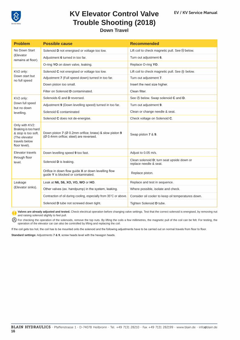
Down Travel
A
A
Solenoid D not energised or voltage too low.
Problem
Adjustment 6 turned in too far.
O-ring YO on down valve, leaking.
Solenoid C not energised or voltage too low.
Adjustment 7 (Full speed down) turned in too far.
Solenoids C and D reversed.
Adjustment 9 (Down levelling speed) turned in too far.
Down levelling speed 9 too fast.
Solenoid D is leaking.
Leak at N6, S6, XO, VO, WO or HO.
Other valves (ex. handpump) in the system, leaking.
Contraction of oil during cooling, especially from 35°C or above.
No Down Start (Elevator remains at floor).
KV2 only:Down start but no full speed
KV2 only:Down full speedbut no down levelling.
Elevator travels through floor level.
Leakage(Elevator sinks).
Turn out adjustment 6.
Replace O-ring YO.
Turn out adjustment 7.
Turn out adjustment 9.
Adjust to 0.05 m/s.
Clean solenoid D; turn seat upside down orreplace needle & seat.
Replace and test in sequence.
Where possible, isolate and check.
Consider oil cooler to keep oil temperatures down.
Lift coil to check magnetic pull. See below.
A
Lift coil to check magnetic pull. See below.
Possible cause Recommended
For checking the operation of the solenoids, remove the top nuts. By lifting the coils a few millimetres, the magnetic pull of the coil can be felt. For testing, the operation of the elevator car can also be controlled by lifting and replacing the coil.
Valves are already adjusted and tested. Check electrical operation before changing valve settings. Test that the correct solenoid is energised, by removing nut and raising solenoid slightly to feel pull.
If the coil gets too hot, the coil has to be mounted onto the solenoid and the following adjustments have to be carried out on normal travels from floor to floor.
Standard settings: Adjustments 7 & 9, screw heads level with the hexagon heads.
A
Down piston too small.
Filter on Solenoid D contaminated. Clean filter.
Insert the next size higher.
Solenoid C contaminated
Solenoid C does not de-energise. Check voltage on Solenoid C.
Clean or change needle & seat.
See below. Swap solenoid C and D.
Only with KV2:Braking is too hard& stop is too soft. (The elevator travels below floor level).
Down piston 7 (Ø 0.2mm orifice; brass) & slow piston 9(Ø 0.4mm orifice; steel) are reversed. Swap piston 7 & 9.
Orifice in down flow guide X or down levelling flow guide Y is blocked or contaminated. Replace piston.
Solenoid D tube not screwed down tight. Tighten Solenoid D tube.

17BLAIN HYDRAULICS · Pfaffenstrasse 1 · D-74078 Heilbronn · Tel. +49 7131 28210 · Fax +49 7131 282199 · www.blain.de · [email protected]
EV / KV Service Manual
EN ISO 9001
KV System Leakage(re-levelling)

18BLAIN HYDRAULICS · Pfaffenstrasse 1 · D-74078 Heilbronn · Tel. +49 7131 28210 · Fax +49 7131 282199 · www.blain.de · [email protected]
EV / KV Service Manual
EN ISO 9001
KV Spare Parts List
apr 16
KV
GmbH
Blain Hydraulics GmbH Tel. +49 7131 28210Pfaff enstrasse 1 Fax +49 7131 28219974078 Heilbronn www.blain.deGermany [email protected]
AS
AH
AF
AN
MO
AR
M
AD
KV1SKV2S
MMA
MM
M
DR6
MO
6
DF
N6
DK
DG
S6
D
DR
MO
DF
DN
DK
DG
S6
M
MMC 5 KV1S, KV2S
S
SESMMSSOSZSFSK
HHO
KS
1
1F1EUF UOU EO
7+9
7ESM9F MSSZ SOYOFIXTXO
Z
FZA V VO
X / Y
KV2PKV2S
SL KS H 7
D/6 CA
1
5
KV2S KV2P
9
Z
DH/DL
0-Ringe: 9x2 P
Z
DH/DL
L KS H S
D/6A
KV1P KV1S
5
91
h
Solenoid Valves Adjustments
Parts List
Flow Valves
In case of down leakage, replace and test in the following order:S6, N6, HO, V complete, XO,(2x XO with KV2).
0-Rings: 5,28x1,78 - V
0-Rings: 9x2 - P
0-Rings: 5,28x1,78 - V
0-Rings: 9x2 - P
0-Rings: 21x2 - P
Pos. No. Item
1 1F Flange - Bypass 1E Adjustment - Bypass EO 0-Ring - Adjustment (3,5x1,5 - P) U Flow Guide - Bypass UO 0-Ring - Bypass (17x1 - V) UF Spring - Bypass
5 5 Adjustment - Up Stop
6 6 Adjustment - Down Acceleration
7+9 7E Adjustment - Down Valve 9F Spring - Down Valve YO 0-Ring - Flow Guide (10x1 - V) XO Seal - Flow Guide (5.28x1.78 - V) XT 0-Ring Disc FI Filter - Down Valve X Down Flow Guide (Brass) Y Down Levelling Flow Guide (Steel) - KV2 Y Down Flow Guide (Steel) - KV1
S SE Adjustment Screw - Relief Valve SM Hexagonal - Relief Valve MS Locking Screw SO 0-Ring - Nipple SZ Nipple - Relief Valve SF Spring - Relief Valve SK Piston - Relief Valve
H H Manual Lowering - Self Closing HO Seal - Man. Lowering (0-Ring 5.28x1.78 - V) HA HA Adjustable Manual Lowering
KS KS Slack Rope Valve
A MM Nut Solenoid AD Collar Solenoid M Coil Solenoid (indicate voltage) AR Tube Solenoid 'Up' MO 0-Ring Solenoid AN Needle Solenoid 'Up' AF Spring Solenoid 'Up' AH Seat Housing 'Up' AS Seat Solenoid 'Up'
C+D M Coil Solenoid (indicate voltage) C DR Tube - Solenoid 'Down', w/o adj. 6 D DR6 Tube Solenoid 'Down', with adj. 6 MO 0-Ring Solenoid DF Spring Solenoid 'Down' C DN Needle Solenoid 'Down' D N6 Needle Solenoid 'Down' (Nipple) C HN Needle Solenoid 'Down' DK Core Solenoid 'Down' DG Seat Housing 'Down'(Solen.D with screen) C S6 Seat Solenoid 'Down' C CO 0-Ring Seat Housing
Z ZA Cylinder Thread Connection V Check Valve VO 0-Ring Check Valve (5,28x1,78 - V) F Main Filter
L L Gauge Shut Off Cock
Designer and Manufacturer of the highest quality control valves & safety componentsfor hydraulic elevators
O-ring: V=FKM-Viton P=NBR-Perbunan

19BLAIN HYDRAULICS · Pfaffenstrasse 1 · D-74078 Heilbronn · Tel. +49 7131 28210 · Fax +49 7131 282199 · www.blain.de · [email protected]
EV / KV Service Manual
EN ISO 9001
Slack Rope Valve `KS´
PurposeIn the case of the operation of the safeties in a 1:2 hydraulic lift system where the weight of the car is no longer carried by the ropes, the electrical supply to the elevator should automatically be switched off. As the ram comes to a stop, usually after about 60 cm, a limited slack rope condition will occur. The KS Slack Rope Valve avoids the ram being lowered by the opening of the manual lowering valve which would otherwise cause additional slack rope. The KS Slack Rope Valve prevents the pressure holding up the ram from being evacuated through the manual lowering valve.
FunctionThe KS valve is adjusted to a pressure just above the pressure produced by the weight of the ram. When under normal operating conditions, the weight of the car acts upon the ram through the 1:2 roping, the resulting pressure is sufficient to open the poppet of the KS valve when the manual lowering H is opened, allowing the car to descend as required. When however the`safeties´ have operated and only the weight of the ram and sheave block are acting upon the hydraulic system, the resulting pressure is too low to open the KS valve. The ram and sheave block can not be lowered.
AdjustmentThe KS is adjusted with a 3 mm Socket Key by turning the screw K `in´ for higher pressure and `out´ for lower pressure. With K turned all the way `in´, then half a turn back out, the unloaded car should descend when the D solenoid alone is energised. Should the car not descend, K must be backed off until the car just begins to descend, then backed off a further half turn to ensure that with cold oil, the car can be lowered as required.
Lock Screw KS 2
Adjustment Screw K
Adjustment Screw K
Down Flange 7- 9
Plug Screw KS 6
∅ 6 mm Ball KS 5
Spring KS 4
0-Ring KS 3
Adjustment 9
K
Manual lowering H

20BLAIN HYDRAULICS · Pfaffenstrasse 1 · D-74078 Heilbronn · Tel. +49 7131 28210 · Fax +49 7131 282199 · www.blain.de · [email protected]
EV / KV Service Manual
EN ISO 9001
Overheating of Power Units - System Leakage
Oil temperatures above 55 °C (130° F) should be avoided, otherwise the efficiency of the pump drops considerably and its life is reduced. Aging of the oil is also accelerated.
Possible causes of overheating:1. Up levelling too long due to the levelling speed being too slow or the slow down switch being set too low.2. Machine room ventilation inadequate.3. The frequency of operation is too high for the normal rate of heat dissipation.
Temporary solution:As a temporary measure to avoid overheating of the oil resulting in the shut down of the elevator, the down speed can be slowed to reduce frequency of operation until a permanent solution is installed.
Cooling systemsa. If the degree of overheating is not excessive and it takes for example two to three hours for the oil temperature to rise from 20°
to 55°C (70° to 130° F), it may be sufficient to improve air circulation around the power unit, for example through the installation of a 0.05 to 0.10 kW ventilator extracting air out of the machine room or through a fan of similar power, blowing air over the power unit.
b. Should the above be inadequate, depending on the size of the elevator, it will be necessary to install a 10-50 l/min. (3 - 13 gpm) pump to circulate the hot oil through an air cooled radiator of about 0.1 to 0.2 fan kW. It is also essential that there is sufficient extraction of warm air out of the machine room or that the cooler is out side of the machine room, for example in the elevator shaft. The effective cooling power of an air cooled radiator should not to be confused with the power of the fan drive which normally need only be 0.1 or 0.2 kW. Normally, the effective cooling power of a cooler need only be approximately ¼ of the main hydraulic elevator motor, in the case of submersible drives.
Cooling systems for the above purpose should be switched into operation when the oil reaches 30° - 35°C (85° - 95° F).
System leakage (re-levelling)The aim of manufacturers of hydraulic elevator control valves is to produce valves with zero leakage. Due to fine contamination in the oil perfect sealing between valve parts may not always be achieved, leading to a slow down leak of the elevator car.
It would become unnecessarily expensive to strive for perfect sealing in every valve in operation. Therefore, because code require-ments assure a safe relevelling system whether descent of the car is caused by valve leakage or through the cooling of the oil in the cylinder pressure system, a minor leakage of the control valve can be tolerated.
1. The European Code EN 81-2 require: that the loaded elevator does not leak downwards by more than 10 mm (3/8“) in 10 minutes. This is the standard used to determine if a valve should be serviced for leakage.
2. For practical reasons, a quicker method for judging valve leakage is to close the ball valve in the cylinder line and observe the gauge showing pressure in the cylinder chamber of the valve. If this pressure falls to zero in less than 20 secs, it may be necessary to service the valve, depending on the diameter of the main ram and sensitivity of the customer.
3. Down sinking giving the impression of leakage can be due to cooling of the oil.
When the elevator is at rest and the temperature of the oil falls, contraction of the oil in the cylinder and piping causes the car to sink. This sinking is very slow but overnight without relevelling could amount to as much as half a meter, depending on the tem-perature drop of the oil and the volume of oil in the cylinder system. The elevator relevelling system, operating normally however, keeps the car at floor level.
4. In the case of Blain EV valves, see page 10 EV and 16 KV indicating where valve down leakage can occur.

21BLAIN HYDRAULICS · Pfaffenstrasse 1 · D-74078 Heilbronn · Tel. +49 7131 28210 · Fax +49 7131 282199 · www.blain.de · [email protected]
EV / KV Service Manual
EN ISO 9001
90
Ref
209
59,10
Ref
158,50
63
118,50
52,60 Ref
Ha
nd
Pu
mp
Ba
ll Va
lve
Pu
mp
Po
rt
Tan
k P
ort
HX
/MX
M6
(Ge
win
de
/Thre
ad
)
119,50
10,25
45,20
100,25
109,25
9,75
1933,50
177,30 Ref
108,75
210,30 Ref
b
Blain Hydraulics GmbH Böllinger Höfe D-74078 Heilbronn Tel.: 07131-28210 Fax: 07131-485216
EV
10
0 ¾
" Loc
hb
ild
T:\EV\0_3-4\2d\
dc
Nam
eEV
10
0 -¾
" mit
Datum
28
.07
.08
IndÄ
nderungD
atumInd
Änderung
Datum
Werkstoff:
Rohm
aße:
gez
gepr1:2
Loc
hb
ild
Zeichnungs-N
r:B
enennungM
aßstab
Mo
nta
g, 2
8. J
uli 2
00
8 1
3:4
1:1
2
BV
, KS &
HP
a

22BLAIN HYDRAULICS · Pfaffenstrasse 1 · D-74078 Heilbronn · Tel. +49 7131 28210 · Fax +49 7131 282199 · www.blain.de · [email protected]
EV / KV Service Manual
EN ISO 9001
332 Ref
74
190 Ref
252 Ref
77,50
207 Ref
70 Ref
122 Ref
HX
/MX
Pu
mp
Po
rt
Tan
k P
ort
Ha
nd
Pu
mp
Ba
ll Va
lve
/Ku
ge
l ha
hn
148
132,50
43,50 89
41
101 53,50
49,8 Ref
IndInd
Änderung
dc
Loc
hb
ild
b
Blain Hydraulics GmbH Böllinger Höfe D-74078 Heilbronn Tel.: 07131-28210 Fax: 07131-485216
T:\EV\1_1-2 und 2\2d\
a
Mo
nta
g, 9
. Mä
rz 20
09
16
:13
:13
29
.07
.08
1:2
EV
10
0 1
½" m
it HX
, HP
, BV
Zeichnungs-N
r:B
enennungM
aßstab
Nam
eD
atum
gepr
gezR
ohmaß
e:
Werkstoff:
Datum
Änderung
Datum
EV
10
0 1
½"
Loc
hb
ild

23BLAIN HYDRAULICS · Pfaffenstrasse 1 · D-74078 Heilbronn · Tel. +49 7131 28210 · Fax +49 7131 282199 · www.blain.de · [email protected]
EV / KV Service Manual
EN ISO 9001
Ref
77
Ref
231
163 Ref
109
282 Ref
106
Ref45
175
129
70
52
35
151
88,60
417 R
ef
232 Ref
Änderung
Ind cb
d
Datum
IndÄ
nderungD
atum
Werkstoff:
Rohm
aße:
gez
gepr
Datum
N
ame
Maß
stabB
enennung
Zeichnungs-N
r:
Blain Hydraulics GmbH Böllinger Höfe D-74078 Heilbronn Tel.: 07131-28210 Fax: 07131-485216

24BLAIN HYDRAULICS · Pfaffenstrasse 1 · D-74078 Heilbronn · Tel. +49 7131 28210 · Fax +49 7131 282199 · www.blain.de · [email protected]
EV / KV Service Manual
EN ISO 9001
74
185
448
41
148 101
43,50 89
132,50
53,50
52,20
77,50
210
70
185
Datum
Änderung
Ind
gepr
Ind
c
Änderung
Datum
Werkstoff:
Rohm
aße:
b
gez
d
Zeichnungs-N
r:B
enennungM
aßstab
Nam
eD
atum
Blain Hydraulics GmbH Böllinger Höfe D-74078 Heilbronn Tel.: 07131-28210 Fax: 07131-485216

25BLAIN HYDRAULICS · Pfaffenstrasse 1 · D-74078 Heilbronn · Tel. +49 7131 28210 · Fax +49 7131 282199 · www.blain.de · [email protected]
EV / KV Service Manual
EN ISO 9001
Nam
eD
atum
gepr
gezR
ohmaße:
Werkstoff:
Datum
KV1P m
it BV, HP, HX, KS
28.07.08
Zeichnungs-Nr:
dbInd
BenennungM
aßstab
Datum
a
IndÄ
nderung
Montag, 28. Juli 2008 10:57:37
c
Änderung
Blain Hydraulics GmbH Böllinger Höfe D-74078 Heilbronn Tel.: 07131-28210 Fax: 07131-485216
T:\KV\KV1P\2d\
1:2KV
1P-LochbildLochbild
106,30 Ref
Ref
65
124
154 Ref
43
14,50
HX/M
X
Zylinder PortPum
p Port
Ha
nd p
ump
Tank Port
M6 (G
ewind
e/Thread
)
36,50
50,70
44,50
7986,50
7,50
16,90
13,30
14,90
57,50

26BLAIN HYDRAULICS · Pfaffenstrasse 1 · D-74078 Heilbronn · Tel. +49 7131 28210 · Fax +49 7131 282199 · www.blain.de · [email protected]
EV / KV Service Manual
EN ISO 9001
14,50
43
65
Ref
200
Ref154
39,70 Ref
30
KV2 - Lochb
ild
T:\KV\KV2\2d\
28.07.08
Montag, 28. Juli 2008 11:35:54
1:2Lochb
ild
Werkstoff:
Blain Hydraulics GmbH Böllinger Höfe D-74078 Heilbronn Tel.: 07131-28210 Fax: 07131-485216
b dcIndÄ
nderungD
atumInd
Änderung
Datum
Zeichnungs-Nr:
BenennungM
aßstabN
ame
Datum
gepr
gezR
ohmaße:
KV2 - BV
KS HP
a
Tank Port
Ha
nd Pum
p
Zylinder Port
S-Block
Pump
Port
M6 (G
ewind
e/Thread
)
49,80
40,60
48,5083,10
90,60
16,90
7,50
13,30
14,90
57,50
65

27BLAIN HYDRAULICS · Pfaffenstrasse 1 · D-74078 Heilbronn · Tel. +49 7131 28210 · Fax +49 7131 282199 · www.blain.de · [email protected]
EV / KV Service Manual
EN ISO 9001
X 7
X 1-2
U 07
2
X 5-6
X 3-4
R
ohmaß
e:gez
gepr.
Werkstoff:
Blain H
ydraulics Gm
bH B
öllinger Höfe D
-74078 Heilbronn T
el.: 07131-28210 Fax: 07131-485216
Nam
eD
atum
P.Mehta
Benennung:
Zeichnungs-N
r.:W
erkstoff:
Rohm
aße:
gez
gepr.
Maß
stab
Bypass F
lowguide / U
mlaufkolben E
insatzgröße :- U
01, 02, 03, 04, 05, 06, 07
Dow
nvalve Flow
guide / Senkkolben E
insatzgröße :- X
1-2, 3-4, 5-6, 7
U 01
0,40
U 02
0,60
U 03
0,50
U 04
0,50
U 06
0,60
U 05
0,60

28BLAIN HYDRAULICS · Pfaffenstrasse 1 · D-74078 Heilbronn · Tel. +49 7131 28210 · Fax +49 7131 282199 · www.blain.de · [email protected]
EV / KV Service Manual
EN ISO 9001
Bypass F
lowguide / U
mlaufkolben E
insatzgröße :- U
0,1, 2, 3, 4, 5, 6, 7
Dow
nvalve Flow
guide / Senkkolben E
insatzgröße :- X
0, 1-2, 3-4, 5-6, 7
dc
Blain Hydraulics GmbH Böllinger Höfe D-74078 Heilbronn Tel.: 07131-28210 Fax: 07131-485216
b
IndÄ
nderungD
atumInd
Änderung
Datum
Werkstoff:
Rohm
aße:
gez
gepr
Datum
Nam
e
E
V 1½
-2" Flow
Guides
Zeichnungs-N
r:B
enennungM
aßstab
EV
1½-2" E
insatzgroße
Senkkolben / D
own F
lowguide X
- 0
3,3
U 3
4
U 2
2,5
Senkkolben / D
own F
lowguide X
1-2
5,5
U 0
1
U 1
1,8
U 5
11
U 6
20
U 4
7S
enkkolben / Dow
n Flow
guide X 3-4
5,5
5,5
U 7
26
Senkkolben / D
own F
lowguide X
7
Senkkolben / D
own F
lowguide X
5-6
22

29BLAIN HYDRAULICS · Pfaffenstrasse 1 · D-74078 Heilbronn · Tel. +49 7131 28210 · Fax +49 7131 282199 · www.blain.de · [email protected]
EV / KV Service Manual
EN ISO 9001
Werkstoff:
b
Dow
nvalve Flow
guide / Senkkolben E
insatzgröße :- Y
10, 20, 40, 80
e f ggfe
00.00.00
00.00.0000.00.00
dc
00.00.00
00.00.00
00.00.00
Blain H
ydraulics Gm
bH B
öllinger Höfe D
-74078 Heilbronn T
el.: 07131-28210 Fax: 07131-485216
b
R
ohmaß
e:gez
gepr.
Datum
Nam
eB
enennung:Z
eichnungs-Nr.:
IndÄ
nderungD
atum
Änderung
Datum
c d
Datum
Änderung
IndD
atumÄ
nderungInd
Maß
stab
gepr.
gezR
ohmaß
e:
Werkstoff:
Bypass F
lowguide / U
mlaufkolben E
insatzgröße :- U
10, 20, 40, 80
U 10
0,80
KV
1P
KV
1S
Y 10
U 40
1
Y 20
Y 40
U 80
5
Y 80A
pplicable for KV
1P &
KV
1S
Bypass F
lowguide (U
)O
pen flange usingspanner 19
Dow
n Flow
guide (Y)
open flange usingspanner 17
U 20
1,10

30BLAIN HYDRAULICS · Pfaffenstrasse 1 · D-74078 Heilbronn · Tel. +49 7131 28210 · Fax +49 7131 282199 · www.blain.de · [email protected]
EV / KV Service Manual
EN ISO 9001
U 10
0,80
X 10
Adj. / E
in. - 7
U 20
1,10
X 20
Adj. / E
in. - 7A
dj. / Ein. - 9
U 80
5
Y 10
Y 10
U 40
1
X 40
Adj. / E
in. - 7
Y 20
Adj. / E
in. - 9
Y 40
Adj. / E
in. - 9X
80
Adj. / E
in. - 7
Dow
n Flow
guide (Y)
open flange usingspanner 17
Do
wn
Flo
wg
uid
e (X
)o
pe
n fla
ng
e u
sing
spa
nn
er 1
7 KV
2PKV
2S
Byp
ass F
low
gu
ide
(U)
Op
en
flan
ge
usin
gsp
an
ne
r 19
Adj. / E
in. - 9
Applicable for K
V2P
& K
V2S
Dow
nvalve Flow
guide (Adjustm
ent 7)/ Senkkolben E
insatzgröße (E
in.7) :- X10, 20, 40, 80........... (B
rass / Messing)
Bypass F
lowguide / U
mlaufkolben E
insatzgröße :- U
10, 20, 40, 80
Dow
nvalve Flow
guide (Adjustm
ent 9)/ Senkkolben E
insatzgröße (E
in.9) :- Y10, 20, 40
Datum
gepr.
gezR
ohmaß
e:
Werkstoff:
Blain H
ydraulics Gm
bH B
öllinger Höfe D
-74078 Heilbronn T
el.: 07131-28210 Fax: 07131-485216
e f ggfe
00.00.00
00.00.0000.00.00
dc
00.00.00
00.00.00
00.00.00b
b
Nam
eB
enennung:Z
eichnungs-Nr.:
IndÄ
nderungD
atumÄ
nderungD
atumW
erkstoff:
Rohm
aße:
gez
gepr.
c d
Datum
Änderung
IndD
atumÄ
nderungInd
Maß
stab

31BLAIN HYDRAULICS · Pfaffenstrasse 1 · D-74078 Heilbronn · Tel. +49 7131 28210 · Fax +49 7131 282199 · www.blain.de · [email protected]
EV / KV Service Manual
EN ISO 9001

32BLAIN HYDRAULICS · Pfaffenstrasse 1 · D-74078 Heilbronn · Tel. +49 7131 28210 · Fax +49 7131 282199 · www.blain.de · [email protected]
EV / KV Service Manual
EN ISO 9001

33BLAIN HYDRAULICS · Pfaffenstrasse 1 · D-74078 Heilbronn · Tel. +49 7131 28210 · Fax +49 7131 282199 · www.blain.de · [email protected]
EV / KV Service Manual
EN ISO 9001

34BLAIN HYDRAULICS · Pfaffenstrasse 1 · D-74078 Heilbronn · Tel. +49 7131 28210 · Fax +49 7131 282199 · www.blain.de · [email protected]
EV / KV Service Manual
EN ISO 9001

35BLAIN HYDRAULICS · Pfaffenstrasse 1 · D-74078 Heilbronn · Tel. +49 7131 28210 · Fax +49 7131 282199 · www.blain.de · [email protected]
EV / KV Service Manual
EN ISO 9001
US gpm.US gpm. 5 10 15 20 25 30 35
20 40 60 80 100 120 140
50 100 150 200 250 300 350 400 20 40 60 80 100 120 140 160 180 200
200 400 600 800 1000 1200 1400 1600 100 200 300 400 500 600 700
01 02 03 04
06
05 0 1 2 3 4 5
6
8 9
10
1 ½" & 2" 2 ½"¾" US gpm.
l/min. l/min. l/min.
50
40
30
20
10
0
700
600
500
400
300
200
100
50
40
30
20
10
0
700
600
500
400
300
200
100
50
40
30
20
10
0
700
600
500
400
300
200
100
bar psi psi barbar psi
Stat
ic p
ress
ure
with
em
pty
car.
Stat
ic p
ress
ure
with
em
pty
car.
Stat
ic p
ress
ure
with
em
pty
car.
Stat
ic p
ress
ure
with
em
pty
car.
Flow Guide Selection Charts
Flow - Pressure Tables (metric)
m/s 0.05 0.10 0.15 0.20 0.25 0.30 0.35 0.40 0.45 0.50 0.55 0.60 0.70 0.80 0.90 1.00 Ø mm cm² l/min 35 9.6 2.9 5.8 8.7 11.5 14 17 20 23 26 29 32 35 40 46 52 58 40 12.6 3.8 7.5 11.3 15.1 19 23 26 30 34 38 41 45 53 60 68 75 45 15.9 4.8 9.5 14.3 19.1 24 29 33 38 43 48 52 57 67 76 86 95 50 19.6 5.9 11.8 17.7 23.6 29 35 41 47 53 59 65 71 82 94 106 118 55 23.8 7.1 14.3 21.4 28.5 36 43 50 57 64 71 78 86 100 114 128 143 60 28.3 8.5 17.0 25.4 33.9 42 51 59 68 76 85 93 102 119 136 153 170 65 33.2 10.0 19.9 29.9 39.8 50 60 70 80 90 100 110 119 139 159 179 199 70 38.5 11.5 23.1 34.6 46.2 58 69 81 92 104 115 127 139 162 185 208 231 75 44.2 13.3 26.5 39.8 53.0 66 80 93 106 119 133 146 159 186 212 239 265 80 50.3 15.1 30.2 45.2 60.3 75 90 106 121 136 151 166 181 211 241 271 302 85 56.7 17.0 34.0 51.1 68.1 85 102 119 136 153 170 187 204 238 272 306 340 90 63.6 19.1 38.2 57.3 76.3 95 115 134 153 172 191 210 229 267 305 344 382 95 70.9 21.3 42.5 63.8 85.1 106 128 149 170 191 213 234 255 298 340 383 425 100 78.5 23.6 47.1 70.7 94.2 118 141 165 188 212 236 259 283 330 377 424 471 105 86.6 26.0 52.0 77.9 103.9 130 156 182 208 234 260 286 312 364 416 468 520 110 95.0 28.5 57.0 85.5 114.0 143 171 200 228 257 285 314 342 399 456 513 570 115 103.9 31.2 62.3 93.5 124.6 156 187 218 249 280 312 343 374 436 499 561 623 120 113.1 33.9 67.9 101.8 135.7 170 204 238 271 305 339 373 407 475 543 611 679 125 122.7 36.8 73.6 110.4 147.3 184 221 258 295 331 368 405 442 515 589 663 736 130 132.7 39.8 79.6 119.5 159.3 199 239 279 319 358 398 438 478 557 637 717 796 140 153.9 46.2 92.4 138.5 184.7 231 277 323 369 416 462 508 554 647 739 831 924 150 176.7 53.0 106.0 159.0 212.1 265 318 371 424 477 530 583 636 742 848 954 1060 160 201.1 60.3 120.6 181.0 241.3 302 362 422 483 543 603 664 724 844 965 1086 1206 170 227.0 68.1 136.2 204.3 272.4 340 409 477 545 613 681 749 817 953 1090 1226 1362 180 254.5 76.3 152.7 229.0 305.4 382 458 534 611 687 763 840 916 1069 1221 1374 1527 190 283.5 85.1 170.1 255.2 340.2 425 510 595 680 766 851 936 1021 1191 1361 1531 1701 200 314.2 94.2 188.5 282.7 377.0 471 565 660 754 848 942 1037 1131 1319 1508 1696 1885 210 346.4 103.9 207.8 311.7 415.6 520 623 727 831 935 1039 1143 1247 1455 1663 1870 2078 220 380.1 114.0 228.1 342.1 456.2 570 684 798 912 1026 1140 1254 1368 1597 1825 2053 2281 240 452.4 135.7 271.4 407.2 542.9 679 814 950 1086 1221 1357 1493 1629 1900 2171 2443 2714 260 530.9 159.3 318.6 477.8 637.1 796 956 1115 1274 1434 1593 1752 1911 2230 2548 2867 3186 280 615.8 184.7 369.5 554.2 738.9 924 1108 1293 1478 1663 1847 2032 2217 2586 2956 3325 3695 300 706.9 212.1 424.1 636.2 848.2 1060 1272 1484 1696 1909 2121 2333 2545 2969 3393 3817 4241
kg 500 750 1000 1500 2000 2500 3000 3500 4000 4500 5000 6000 7000 8000 9000 10000 Ø mm cm² bar 35 9.6 51 76 102 153 204 255 306 357 408 459 510 612 714 816 918 1020 40 12.6 39 59 78 117 156 195 234 273 312 351 390 468 546 625 703 781 45 15.9 31 46 62 93 123 154 185 216 247 278 308 370 432 493 555 617 50 19.6 25 38 50 75 100 125 150 175 200 225 250 300 350 400 450 500 55 23.8 21 31 41 62 83 103 124 145 165 186 206 248 289 330 372 413 60 28.3 17 26 35 52 69 87 104 121 139 156 173 208 243 278 312 347 65 33.2 15 22 30 44 59 74 89 103 118 133 148 177 207 237 266 296 70 38.5 13 19 26 38 51 64 76 89 102 115 127 153 178 204 229 255 75 44.2 11 17 22 33 44 56 67 78 89 100 111 133 155 178 200 222 80 50.3 9.8 15 20 29 39 49 59 68 78 88 98 117 137 156 176 195 85 56.7 8.6 13 17 26 35 43 52 61 69 78 86 104 121 138 156 173 90 63.6 7.7 12 15 23 31 39 46 54 62 69 77 93 108 123 139 154 95 70.9 6.9 10 14 21 28 35 42 48 55 62 69 83 97 111 125 138 100 78.5 6.2 9.4 13 19 25 31 38 44 50 56 62 75 87 100 112 125 105 86.6 5.7 8.5 11 17 23 28 34 40 45 51 57 68 79 91 102 113 110 95.0 5.2 7.7 10 16 21 26 31 36 41 47 52 62 72 83 93 103 115 103.9 4.7 7.1 9.4 14 19 24 28 33 38 43 47 57 66 76 85 94 120 113.1 4.3 6.5 8.7 13 17 22 26 30 35 39 43 52 61 69 78 87 125 122.7 4.0 6.0 8.0 12 16 20 24 28 32 36 40 48 56 64 72 80 130 132.7 3.7 5.5 7.4 11 15 19 22 26 30 33 37 44 52 59 67 74 140 153.9 3.2 4.8 6.4 9.6 13 16 19 22 26 29 32 38 45 51 57 64 150 176.7 2.8 4.2 5.6 8.3 11 14 17 19 22 25 28 33 39 44 50 56 160 201.1 2.4 3.7 4.9 7.3 9.8 12 15 17 20 22 24 29 34 39 44 49 170 227.0 2.2 3.2 4.3 6.5 8.6 11 13 15 17 19 22 26 30 35 39 43 180 254.5 1.9 2.9 3.9 5.8 7.7 9.6 12 14 15 17 19 23 27 31 35 39 190 283.5 1.7 2.6 3.5 5.2 6.9 8.6 10 12 14 16 17 21 24 28 31 35 200 314.2 1.6 2.3 3.1 4.7 6.2 7.8 9.4 11 13 14 16 19 22 25 28 31 210 346.4 1.4 2.1 2.8 4.2 5.7 7.1 8.5 9.9 11 13 14 17 20 23 26 28 220 380.1 1.3 1.9 2.6 3.9 5.2 6.5 7.7 9.0 10.3 12 13 16 18 21 23 26 240 452.4 1.1 1.6 2.2 3.3 4.3 5.4 6.5 7.6 8.7 9.8 11 13 15 17 20 22 260 530.9 0.9 1.4 1.8 2.8 3.7 4.6 5.5 6.5 7.4 8.3 9.2 11 13 15 17 19 280 615.8 0.8 1.2 1.6 2.4 3.2 4.0 4.8 5.6 6.4 7.2 8.0 9.6 11 13 14 16 300 706.9 0.7 1.0 1.4 2.1 2.8 3.5 4.2 4.9 5.6 6.2 6.9 8.3 9.7 11 13 14
Ram Ø • Area • Load • Pressure
Ram Ø • Area • Speed • Flow
in² = 6,45 cm² 1 in = 25,4 mm 1 m/s = 197 ft/min 1 Imp. gpm = 4,55 l/min 1 US gmp = 3,79 l/min 1 kg = 2,2 lbs 1 bar = 14,7 psi

36BLAIN HYDRAULICS · Pfaffenstrasse 1 · D-74078 Heilbronn · Tel. +49 7131 28210 · Fax +49 7131 282199 · www.blain.de · [email protected]
EV / KV Service Manual
EN ISO 9001
Flow - Pressure Tables (US gpm/psi)
Ram Ø • Area • Load • Pressure
Ram Ø • Area • Speed • Flow ft/min 10 20 30 40 50 60 70 80 90 100 110 120 140 160 180 200Ø inch in² US gpm1.4 1.5 0.8 1.6 2.4 3.2 4.0 4.8 5.6 6.4 7.2 8.0 8.8 9.6 11.2 12.8 14.4 16.01.6 2.0 1.0 2.1 3.1 4.2 5.2 6.3 7.3 8.4 9.4 10.5 11.5 12.5 14.6 16.7 18.8 20.91.8 2.5 1.3 2.6 4.0 5.3 6.6 7.9 9.3 10.6 11.9 13.2 14.6 15.9 18.5 21.2 23.8 26.52.0 3.1 1.6 3.3 4.9 6.5 8.2 9.8 11.4 13.1 14.7 16.3 18.0 19.6 22.9 26.1 29.4 32.72.2 3.8 2.0 4.0 5.9 7.9 9.9 11.9 13.8 15.8 17.8 19.8 21.7 23.7 27.7 31.6 35.6 39.52½ 4.9 2.6 5.1 7.7 10.2 12.8 15.3 17.9 20.4 23.0 25.5 28.1 30.6 35.7 40.8 45.9 51.02.6 5.3 2.8 5.5 8.3 11.0 13.8 16.6 19.3 22.1 24.8 27.6 30.4 33.1 38.6 44.2 49.7 55.22¾ 5.9 3.1 6.2 9.3 12.4 15.4 18.5 21.6 24.7 27.8 30.9 34.0 37.1 43.2 49.4 55.6 61.83.0 7.1 3.7 7.3 11.0 14.7 18.4 22.0 25.7 29.4 33.1 36.7 40.4 44.1 51.4 58.8 66.1 73.53.2 8.0 4.2 8.4 12.5 16.7 20.9 25.1 29.3 33.4 37.6 41.8 46.0 50.2 58.5 66.9 75.3 83.63½ 9.6 5.0 10.0 15.0 20.0 25.0 30.0 35.0 40.0 45.0 50.0 55.0 60.0 70.0 80.0 90.0 100.03.6 10.2 5.3 10.6 15.9 21.2 26.5 31.7 37.0 42.3 47.6 52.9 58.2 63.5 74.1 84.7 95.2 105.83.8 11.3 5.9 11.8 17.7 23.6 29.5 35.4 41.3 47.2 53.1 59.0 64.9 70.7 82.5 94.3 106.1 117.94.0 12.6 6.5 13.1 19.6 26.1 32.7 39.2 45.7 52.3 58.8 65.3 71.9 78.4 91.5 104.5 117.6 130.74.2 13.9 7.2 14.4 21.6 28.8 36.0 43.2 50.4 57.6 64.8 72.0 79.2 86.4 100.8 115.2 129.6 144.04⅜ 15.0 7.8 15.6 23.4 31.3 39.1 46.9 54.7 62.5 70.3 78.1 86.0 93.8 109.4 125.0 140.7 156.34½ 15.9 8.3 16.5 24.8 33.1 41.3 49.6 57.9 66.1 74.4 82.7 90.9 99.2 115.8 132.3 148.8 165.44.8 18.1 9.4 18.8 28.2 37.6 47.0 56.4 65.8 75.3 84.7 94.1 103.5 112.9 131.7 150.5 169.3 188.15.0 19.6 10.2 20.4 30.6 40.8 51.0 61.2 71.5 81.7 91.9 102.1 112.3 122.5 142.9 163.3 183.7 204.15½ 23.2 12.1 24.1 36.2 48.3 60.4 72.4 84.5 96.6 108.6 120.7 132.8 144.9 169.0 193.1 217.3 241.45½ 23.8 12.4 24.7 37.1 49.4 61.8 74.1 86.5 98.8 111.2 123.5 135.9 148.2 172.9 197.6 222.3 247.06.0 28.3 14.7 29.4 44.1 58.8 73.5 88.2 102.9 117.6 132.3 147.0 161.7 176.4 205.8 235.2 264.6 294.06½ 33.2 17.3 34.5 51.8 69.0 86.3 103.5 120.8 138.0 155.3 172.5 189.8 207.0 241.5 276.0 310.5 345.06.8 36.3 18.9 37.8 56.6 75.5 94.4 113.3 132.2 151.0 169.9 188.8 207.7 226.6 264.3 302.1 339.8 377.67.0 38.5 20.0 40.0 60.0 80.0 100.0 120.0 140.0 160.1 180.1 200.1 220.1 240.1 280.1 320.1 360.1 400.17½ 44.2 23.0 45.9 68.9 91.9 114.8 137.8 160.8 183.7 206.7 229.7 252.6 275.6 331.5 367.5 413.4 459.38.0 50.3 26.1 52.3 78.4 104.5 130.7 156.8 182.9 209.0 235.2 261.3 287.4 313.6 365.8 418.1 470.4 522.68½ 56.7 29.5 59.0 88.5 118.0 147.5 177.0 206.5 236.0 265.5 295.0 324.5 354.0 413.0 472.0 531.0 590.08.8 60.8 31.6 63.2 94.9 126.5 158.1 189.7 221.3 252.9 284.6 316.2 347.8 379.4 442.7 505.9 569.1 632.49½ 70.9 36.8 73.7 110.5 147.4 184.2 221.1 257.9 294.8 331.6 368.5 405.3 442.2 515.9 589.6 663.3 737.010⅝ 88.7 46.1 92.2 138.3 184.4 230.5 276.6 322.6 368.7 414.8 460.9 507.0 553.1 645.3 737.5 829.7 921.911.2 98.5 51.2 102.4 153.6 204.9 256.1 307.3 358.5 409.7 460.9 512.2 563.4 614.6 717.0 819.5 921.9 1024.312.0 113.1 58.8 117.6 176.4 235.2 294.0 352.8 411.6 470.4 529.1 587.9 646.7 705.5 823.1 940.7 1058.3 1175.9
lbs 1100 1650 2200 3300 4400 5500 6600 7700 8800 10000 11000 13200 15400 17600 19800 22000Ø inch in² psi 1.4 1.5 714.6 1071.9 1429.1 2143.7 2858.3 3572.9 4287.4 5002.0 5716.6 6496.1 7145.7 8574.9 10004.0 11433.2 12862.3 14291.51.6 2.0 547.1 820.6 1094.2 1641.3 2188.4 2735.5 3282.6 3829.7 4376.8 4973.6 5471.0 6565.1 7659.3 8753.5 9847.7 10941.91.8 2.5 432.3 648.4 864.5 1296.8 1729.1 2161.4 2593.6 3025.9 3458.2 3929.8 4322.7 5187.3 6051.8 6916.4 7780.9 8645.52.0 3.1 350.1 525.2 700.3 1050.4 1400.6 1750.7 2100.8 2451.0 2801.1 3183.1 3501.4 4201.7 4902.0 5602.3 6302.5 7002.82.2 3.8 289.4 434.1 578.7 868.1 1157.5 1446.9 1736.2 2025.6 2315.0 2630.7 2893.7 3472.5 4051.2 4630.0 5208.7 5787.52½ 4.9 224.1 336.1 448.2 672.3 896.4 1020.5 1344.5 1568.6 1792.7 2037.2 2240.9 2689.1 3137.3 3585.4 4033.6 4481.82.6 5.3 207.2 310.8 414.4 621.6 828.7 1035.9 1243.1 1450.3 1657.5 1883.5 2071.8 2486.2 2900.6 3314.9 3729.3 4143.72¾ 5.9 185.2 277.8 370.4 555.6 740.8 926.0 1111.2 1296.4 1481.6 1683.6 1852.0 2222.4 2592.8 2963.2 3333.6 3704.03.0 7.1 155.6 233.4 311.2 466.9 622.5 778.1 933.7 1089.3 1244.9 1414.7 1556.2 1867.4 2178.7 2489.9 2801.1 3112.43.2 8.0 136.8 205.2 273.5 410.3 547.1 683.9 820.6 957.4 1094.2 1243.4 1367.7 1641.3 1914.8 2188.4 2461.9 2735.53½ 9.6 114.3 171.5 228.7 343.0 457.3 571.7 686.0 800.3 914.7 1039.4 1143.3 1372.0 1600.6 1829.3 2058.0 2286.63.6 10.2 108.1 162.1 216.1 324.2 432.3 540.3 648.4 756.5 864.5 982.4 1080.7 1296.8 1513.0 1729.1 1945.2 2161.43.8 11.3 97.0 145.5 194.0 291.0 388.0 485.0 582.0 678.9 775.9 881.7 969.9 1163.9 1357.9 1551.9 1745.9 1939.84.0 12.6 87.5 131.3 175.1 262.6 350.1 437.7 525.2 612.7 700.3 795.8 875.4 1050.4 1225.5 1400.6 1575.6 1750.74.2 13.9 79.4 119.1 158.8 238.2 317.6 397.0 476.4 555.8 635.2 721.8 794.0 952.8 1111.6 1270.4 1429.1 1587.94⅜ 15.0 73.2 109.8 146.3 219.5 292.7 365.9 439.0 512.2 585.4 665.2 731.7 878.1 1024.4 1170.8 1317.1 1463.44½ 15.9 69.2 103.7 138.3 207.5 276.7 345.8 415.0 484.1 553.3 628.8 691.6 830.0 968.3 1106.6 1244.9 1383.34.8 18.1 60.8 91.2 121.6 182.4 243.2 303.9 364.7 425.5 486.3 552.6 607.9 729.5 851.0 972.6 1094.2 1215.85.0 19.6 56.0 84.0 112.0 168.1 224.1 280.1 336.1 392.2 448.2 509.3 560.2 672.3 784.3 896.4 1008.4 1120.55½ 23.2 47.4 71.1 94.7 142.1 189.5 236.9 284.2 331.6 379.0 430.6 473.7 568.4 663.2 757.9 852.7 947.45½ 23.8 46.3 69.4 92.6 138.9 185.2 231.5 277.8 324.1 370.4 420.9 463.0 555.6 648.2 740.8 833.4 926.06.0 28.3 38.9 58.4 77.8 116.7 155.6 194.5 233.4 272.3 311.2 353.7 389.0 466.9 544.7 622.5 700.3 778.16½ 33.2 33.1 49.7 66.3 99.4 132.6 165.7 198.9 232.0 265.2 301.4 331.5 397.8 464.1 530.4 596.7 663.06.8 36.3 30.3 45.4 60.6 90.9 121.2 151.4 181.7 212.0 242.3 275.4 302.9 363.5 424.0 484.6 545.2 605.87.0 38.5 28.6 42.9 57.2 85.7 114.3 142.9 171.5 200.1 228.7 259.8 285.8 343.0 400.2 457.3 514.5 571.77½ 44.2 24.9 37.3 49.8 74.7 99.6 124.5 149.4 174.3 199.2 226.4 249.0 298.8 348.6 398.4 448.2 498.08.0 50.3 21.9 32.8 43.8 65.7 87.5 109.4 131.3 153.2 175.1 198.9 218.8 262.6 306.4 350.1 393.9 437.78½ 56.7 19.4 29.1 38.8 58.2 77.5 96.9 116.3 135.7 155.1 176.2 193.8 232.6 271.4 310.2 348.9 387.78.8 60.8 18.1 27.1 36.2 54.3 72.3 90.4 108.5 126.6 144.7 164.4 180.9 217.0 253.2 289.4 325.5 361.79½ 70.9 15.5 23.3 31.0 46.6 62.1 77.6 93.1 108.6 124.1 141.1 155.2 186.2 217.3 248.3 279.3 310.410⅝ 88.7 12.4 18.6 24.8 37.2 49.6 62.0 74.4 86.8 99.3 112.8 124.1 148.9 173.7 198.5 223.3 248.111.2 98.5 11.2 16.7 22.3 33.5 44.7 55.8 67.0 78.2 89.3 101.5 111.7 134.0 156.3 178.6 201.0 223.312.0 113.1 9.7 14.6 19.5 29.2 38.9 48.6 58.4 68.1 77.8 88.4 97.3 116.7 136.2 155.6 175.1 194.5
� � �
� � �
in² = 6,45 cm² 1 in = 25,4 mm 1 m/s = 197 ft/min 1 Imp. gpm = 4,55 l/min 1 US gmp = 3,79 l/min 1 kg = 2,2 lbs 1 bar = 14,7 psi
37BLAIN HYDRAULICS · Pfaffenstrasse 1 · D-74078 Heilbronn · Tel. +49 7131 28210 · Fax +49 7131 282199 · www.blain.de · [email protected]
EV / KV Service Manual
EN ISO 9001
Notes

38BLAIN HYDRAULICS · Pfaffenstrasse 1 · D-74078 Heilbronn · Tel. +49 7131 28210 · Fax +49 7131 282199 · www.blain.de · [email protected]
EV / KV Service Manual
EN ISO 9001
Notes

39BLAIN HYDRAULICS · Pfaff enstrasse 1 · D-74078 Heilbronn · Tel. +49 7131 28210 · Fax +49 7131 282199 · www.blain.de · [email protected]
EV / KV Service Manual
EN ISO 9001

BLAIN HYDRAULICSDesigner and Manufacturer of the highest quality control valves & safety components for hydraulic elevators
Blain USA
Blain Germany
Blain India
Blain Brazil
Blain Turkey
Blain GermanyBlain Hydraulics GmbHPfa� enstrasse 1 · 74078 Heilbronn · GermanyPhone +49 7131 28210 · Fax +49 7131 282199Mail: [email protected] · www.blain.de
Blain TurkeyBlain Hidrolik Dış Ticaret Ltd ŞtiAYTOP Gida Sitesi G17 · Sultanbeyli 34935 · Istanbul · TurkeyPhone +90 216 5920800Mail: [email protected] · www.blain.com.tr
Blain IndiaBlain India PVT LTDUnit No. 270 · BIdg No. C/7 · Bhumi World · Pimplas VillageMumbai-Nashik Highway · Thane 421302 · IndiaPhone +91 9819130854Mail: [email protected] · www.blain.de
Blain USAHYDRASTAR1275 Bloomfi eld Ave. Bldg. 7, Ste. 41 · Fairfi eld, NJ 07004 · USAPhone: +1 973.276.8490 · Fax +1 973.288.2618Mail: [email protected] · www.blain.de
Blain BrazilDAIKEN ELEVADORESAv. São Gabriel, 481 · Planta Bom Jesus · Colombo/PR - CEP 83404-000Phone +55 41 3621 8417 · Fax +55 41 3621 8001Mail: [email protected] · www.blain.de