eva-dts 6.1.1 new
DESCRIPTION
Very nice, much wowTRANSCRIPT
Last update: December 2012 Page 1 of 311
European Vending Association aisbl
44 rue Van Eyck, 1000 Brussels, Belgium Tel.: +32 (0)2 512 00 75 - Fax: + 32 (0)2 502 23 42 [email protected] - www.vending-europe.eu
DATA TRANSFER STANDARD
EVA DTS 6.1.1
In cooperation with
Copyright by the European Vending Association
All rights reserved
No part of this publication may be reproduced or transmitted, in any form
or by any means, electronic, mechanical, photocopying, recording or otherwise, or stored in any retrieval system of any nature, without the written permission of EVA.
Last update: December 2012 Page 2 of 311
European Vending Association aisbl
44 rue Van Eyck, 1000 Brussels, Belgium Tel.: +32 (0)2 512 00 75 - Fax: + 32 (0)2 502 23 42 [email protected] - www.vending-europe.eu
Table of Contents
CHAPTER 1 - INTRODUCTION TO EVA-DTS VERSION 6.1.1 .................. 7 INTRODUCTION ...................................................................................... 7 1.1 AIM OF THE STANDARD ...................................................................... 8 1.2 GLOSSARY OF TERMS USED IN THE STANDARD ..................................... 10 1.3 EVOLUTION OF THE STANDARD .......................................................... 11
1.3.1 Migration to newer technologies .................................................... 12 1.4 APPLICATION OF THE STANDARD ........................................................ 14
CHAPTER 2 - DATA FORMAT AND PRESENTATION ............................ 16 2.1 REPORT ........................................................................................... 16
2.1.1 Definition of a Report ................................................................... 16 2.1.2 Syntax of a Report ....................................................................... 16
2.2 DATA SEGMENTS .............................................................................. 17 2.2.1 Definition of A Data Segment ........................................................ 17 2.2.2 Syntax of A Data Segment ............................................................ 18 2.2.3 Examples of Actual Data Segments ................................................ 19
2.3 DATA ELEMENTS ............................................................................... 20 2.3.1 Definition of a Data Element ......................................................... 20 2.3.2 Data Element Format ................................................................... 20
2.4 MANDATORY HEADERS AND TRAILERS ................................................. 22 2.4.1 Application Header and Trailer (DXS and DXE) ................................. 22 2.4.2 Transaction Set Header and Trailer ................................................ 24 2.4.3 Data Record Integrity Check ......................................................... 25 2.4.4 Example Report ........................................................................... 27
2.5 RECOMMENDED AUDIT REPORT .......................................................... 28 2.6 RESETTING INTERVAL DATA ELEMENTS ............................................... 42
2.6.1 Interval Data Elements (All) .......................................................... 42 2.6.2 Interval Data Elements (Selective) ................................................. 43
2.7 DATA REPORTING ............................................................................. 44 2.7.1 Selective Reporting of Data ........................................................... 44 2.7.2 Reporting of Data using lists ......................................................... 45
2.8 EVENT REPORTING INSTRUCTIONS ..................................................... 45 2.8.1 Event Inclusion ........................................................................... 46 2.8.2 Event Resetting / Clearing ............................................................ 46 2.8.3 Event Reporting Examples ............................................................ 47
Last update: December 2012 Page 3 of 311
European Vending Association aisbl
44 rue Van Eyck, 1000 Brussels, Belgium Tel.: +32 (0)2 512 00 75 - Fax: + 32 (0)2 502 23 42 [email protected] - www.vending-europe.eu
CHAPTER 3 - DATA TRANSFER USING ENHANCED DDCMP ................. 52 3.1 SCOPE ............................................................................................ 52
3.1.1 Terms ........................................................................................ 53 3.2 INTERFACE OVERVIEW ...................................................................... 53
3.2.1 General Data Transfer Operation ................................................... 57 3.3 PHYSICAL LEVEL DETAILS .................................................................. 58 3.4 DATALINK LEVEL .............................................................................. 58
3.4.1 Data Format ............................................................................... 59 3.4.2 Basic Transmission Parameters ...................................................... 60 3.4.3 Message Framing ......................................................................... 62 3.4.4 Data Length Restrictions ............................................................... 62 3.4.5 Cyclic Redundancy Check ............................................................. 63 3.4.6 Datalink Timings/Restrictions ........................................................ 64
3.5 SESSION LEVEL ................................................................................ 65 3.5.2 Error Handling ............................................................................. 67
3.6 APPLICATION LEVEL DETAILS ............................................................. 70 3.6.1 Message Types ............................................................................ 70 3.6.2 Control Messages ........................................................................ 74 3.6.3 Data Message Header .................................................................. 79 3.6.4 Data Messages ............................................................................ 81 3.6.5 Message Sequence ...................................................................... 95
3.7 COMMUNICATIONS SESSION .............................................................. 96 3.7.1 Initialise Link .............................................................................. 96 3.7.2 Data Message Transfer ................................................................. 97 3.7.3 Turn Around Time ...................................................................... 101
CHAPTER 4 - DATA TRANSFER USING DEX/UCS ............................... 102 4.1 SCOPE .......................................................................................... 102 4.2 INTERFACE OVERVIEW .................................................................... 103 4.3 PHYSICAL LEVEL DETAILS ................................................................ 104 4.4 DATA LINK LEVEL DETAILS ............................................................. 104 4.5 SESSION LEVEL DETAILS ................................................................. 106
4.5.1 Vending Machine Session Establishment ....................................... 107 4.5.2 Business System Computer Session Establishment ......................... 108 4.5.3 Session Establishment Formats ................................................... 108 4.5.4 Communication IDs ................................................................... 112
Last update: December 2012 Page 4 of 311
European Vending Association aisbl
44 rue Van Eyck, 1000 Brussels, Belgium Tel.: +32 (0)2 512 00 75 - Fax: + 32 (0)2 502 23 42 [email protected] - www.vending-europe.eu
4.5.5 Operation Request ..................................................................... 112 4.5.6 Revision & Level ........................................................................ 113 4.5.7 Response Codes ........................................................................ 113 4.5.8 Timers and Limits ...................................................................... 114
4.6 SESSION / APPLICATION LEVEL DATA TRANSFER ................................ 116 4.6.1 Data Transfer Formats ............................................................... 116 4.6.2 Overall Data Format ................................................................... 118
4.7 DEX DATA TRANSFER EXAMPLES ....................................................... 119 4.8 APPLICABLE DEX/UCS DOCUMENTATION ............................................ 122
CHAPTER 5 - APPLICATION NOTES - DATA ..................................... 124 5.1. APPLICATION NOTES FOR THE DATA ................................................. 124
5.1.1 Data Element Configuration ........................................................ 124 5.1.2 Manual Data Entry ..................................................................... 126 5.1.3 Repeating Data Groups .............................................................. 127 5.1.4 Selective reporting and selective resetting of data elements ............ 128 5.1.5 Element Length ......................................................................... 132 5.1.6 Data Element Format (Type) ....................................................... 133 5.1.7 Price Lists ................................................................................. 134 5.1.8 Mixed Payment Reporting ........................................................... 135 5.1.9 Difference between “zero price vends” and “free vends” .................. 137 5.1.10 Product Level related elements .................................................. 137
5.2. EXAMPLES OF UPDATING DTS DATA FIELDS ...................................... 137 5.2.1 Continuous update .................................................................... 138 5.2.2 Value Token reporting ............................................................... 138 5.2.3 Vend Examples ........................................................................ 139 5.2.4 Cash Examples .......................................................................... 166
CHAPTER 6 - APPLICATION NOTES - DDCMP .................................. 171 6.1 APPLICATION NOTES FOR THE ENHANCED DDCMP ............................... 171
6.1.1 Byte Format (see 3.4.1.2 and 3.6.4.1.1) ....................................... 171 6.1.2 Cyclic Redundancy Check (see 3.4.5) ........................................... 172 6.1.3 Enhanced DDCMP Features ......................................................... 175 6.1.4 Command Messages & Responses ................................................ 176 6.1.5 Message Sequences - End of Communications Sequence ................. 177 6.1.6 Security-Passcode usage ............................................................ 178 6.1.7 Configuration features ................................................................ 179 6.1.8 Slave address setting ................................................................. 179
Last update: December 2012 Page 5 of 311
European Vending Association aisbl
44 rue Van Eyck, 1000 Brussels, Belgium Tel.: +32 (0)2 512 00 75 - Fax: + 32 (0)2 502 23 42 [email protected] - www.vending-europe.eu
6.2 EXAMPLE COMMUNICATION SEQUENCES ............................................ 180 6.2.1 Standard Data Collection Examples .............................................. 180 6.2.2 Error Handling Sequences ........................................................... 189
CHAPTR 7 - DATA TRANSFER PHYSICAL LAYERS .............................. 195 7.1 SCOPE .......................................................................................... 195 7.2 OVERVIEW ..................................................................................... 195 7.3 HARDWIRED PHYSICAL LEVEL DETAILS ............................................. 196
7.3.1 Vending Machine Device (VMD) ................................................... 196 7.3.2 Data Carrier (DC) ..................................................................... 196 7.3.3 Business System Computer (BSC) ............................................... 197
7.4 OPTICAL IRDA PHYSICAL LEVEL DETAILS ........................................... 198 7.4.1 Optical Characteristics ................................................................ 198 7.4.2 Receiver Characteristics ............................................................. 200 7.4.3 Physical Separation of Optics ...................................................... 201
APPENDIX A - DATA DICTIONARY ................................................. 202 A.1 DEFINITIONS ................................................................................. 202
APPENDIX B - MANUFACTURER CODES .......................................... 267
APPENDIX C - EVENT LIST ............................................................ 275 C.1 INTRODUCTION .............................................................................. 275 C.2 EVENT LISTS .................................................................................. 275
C.2.1 Equipment Event Codes .............................................................. 276 C.2.2 Operational Event Codes ............................................................ 277 C.2.3 Specific Event Codes .................................................................. 278 C.2.4 Example Code ........................................................................... 278 C.2.5 Manufacturer Specific or New Codes ............................................. 278 C.2.6 Additional Event Information ....................................................... 279
Last update: December 2012 Page 6 of 311
European Vending Association aisbl
44 rue Van Eyck, 1000 Brussels, Belgium Tel.: +32 (0)2 512 00 75 - Fax: + 32 (0)2 502 23 42 [email protected] - www.vending-europe.eu
Table 1: COIN MECHANISM ................................................................. 280 Table 2: CUP SYSTEM ......................................................................... 282 Table 3: CONTROL SYSTEM ................................................................. 284 Table 4: HOT DRINKS SYSTEM ............................................................ 286 Table 5: BREWER/ESPRESSO UNIT ....................................................... 287 Table 6: WATER SYSTEM .................................................................... 288 Table 7: CABINET/DOOR .................................................................... 289 Table 8: COLD DRINK DISPENSING SYSTEM .......................................... 290 Table 9: COMMUNICATIONS ................................................................ 292 Table 10: FOOD, SNACK, OR CAN/BOTTLE SYSTEM ................................ 293 Table 11: CASHLESS 1 SYSTEM ........................................................... 295 TABLE 11a : CASHLESS 2 SYSTEM ....................................................... 296 Table 12: PRODUCT ........................................................................... 297 Table 13: MICROWAVE ....................................................................... 298 Table 14: BILL VALIDATOR ................................................................. 299 Table 15: REFRIGERATION SYSTEM ..................................................... 300 Table 16: OPERATIONS REQUEST ........................................................ 301 Table 17: SERVICE RELATED ............................................................... 303 Table 18: CUSTOMER INDUCED ........................................................... 305 Table 19: RETURN VISITS ................................................................... 306 Table 20: MACHINE HISTORY .............................................................. 306 Table 21:CASH COLLECTION ............................................................... 307
C.3. PROCESS FOR MAINTAINING EVENT LIST .......................................... 308
APPENDIX D - CHANGES .............................................................. 309 D.1. EXPLANATION OF VERSION 6.1 ....................................................... 309 D.2. PROTOCOL LAYERS AND PHYSICAL LAYERS ....................................... 309 D.3. DATA FORMAT ............................................................................... 309 D.4. APPLICATION NOTES DATA ............................................................. 309 D.5. DATA DICTIONARY ........................................................................ 309
APPENDIX E - CHANGE PROCEDURE .............................................. 311
Last update: December 2012 Page 7 of 311
European Vending Association aisbl
44 rue Van Eyck, 1000 Brussels, Belgium Tel.: +32 (0)2 512 00 75 - Fax: + 32 (0)2 502 23 42 [email protected] - www.vending-europe.eu
CHAPTER 1 - INTRODUCTION TO EVA-DTS VERSION 6.1.1
Introduction
Foreword to EVA-DTS Version 6.1.1
Version 6.1.1 of the EVA-DTS replaces Version 6.1 as the current version of EVA-DTS.
The fundamental protocols of the EVA-DTS standard have been preserved but additional information and explanation has been provided to aid implementation and remove ambiguity.
Appendix D outlines the significant changes to the standard and some of the implications.
This voluntary standard contains basic requirements for vending machines within the limitations given below. These requirements are based on sound engineering principles, research, field experience and an appreciation of the problems of manufacture, installation and use derived from consultation with and information obtained from manufacturers, users, regulatory agencies and others having specialized experience. These requirements are subject to revision as further experience and investigation may show it necessary or desirable.
EVA, in performing its functions in accordance with its objectives, does not assume or under-take to discharge any responsibility of the manufacturer or any other party. The opinions and findings of EVA represent its professional judgment given with due consideration to the necessary limitations of practical operation and state of the art at the time the Standard is processed. EVA shall not be responsible to anyone for use or reliance upon this Standard by anyone. EVA shall not incur any obligation or liability for damages, including consequential damages, arising out of or in connection with the use, interpretation of, or reliance upon this Standard.
Last update: December 2012 Page 8 of 311
European Vending Association aisbl
44 rue Van Eyck, 1000 Brussels, Belgium Tel.: +32 (0)2 512 00 75 - Fax: + 32 (0)2 502 23 42 [email protected] - www.vending-europe.eu
1.1 AIM OF THE STANDARD
The aim of EVA-DTS is provide a standard format for data which is required by operators of vending machines. The standard defines the structure of common data
elements and describes the means for the transfer of data
The abbreviation means European Vending Association Data Transfer Standard.
The Standard is based on the concept that data of different types are required to be entered into vending machines to enable the machine to deliver the service required.
Additionally sales and event data accumulated and stored in the machine are required to be accessed by Vending Machine Operators and transferred to management systems
for either commercial or technical control purposes.
The transfer of EVA-DTS data is intended to be made by electronic means rather than printing reports which have to be processed manually. The original method for the
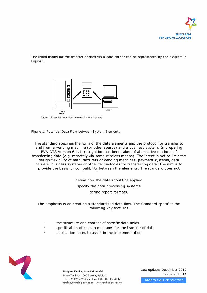
transfer of the data which is described in this document is a portable “Data Carrier”. The elements in the path of data transfer are
• Vending Machine Device (VMD)– This element is either a vending machine or some other device such as a payment system or data collection device. This element will require some form of data input for setting operating parameters. Also during the execution of its specific function, transaction data will be accumulated and stored which may be of use in the management of the vending service.
• Data Carrier – this a device, the form of which is not defined, whose role is to receive, store and transmit data to other elements in a total system. Initially the data carrier was conceived to be a handheld device, but may be a device for collecting data and transmitting data remotely. E.g telemetry
• Business System Computer - A computer which might receive data obtained from individual vending machines (or other Sources) and manipulate the data to provide the vending operator with management information to control the operation. It might be that the computer systems employed by the business generate some parameters which need to be transferred to the Vending machines (or other Sources). The data carrier would be the means of achieving the data flow.
Last update: December 2012 Page 9 of 311
European Vending Association aisbl
44 rue Van Eyck, 1000 Brussels, Belgium Tel.: +32 (0)2 512 00 75 - Fax: + 32 (0)2 502 23 42 [email protected] - www.vending-europe.eu
The initial model for the transfer of data via a data carrier can be represented by the diagram in Figure 1.
Figure 1: Potential Data Flow between System Elements
The standard specifies the form of the data elements and the protocol for transfer to and from a vending machine (or other source) and a business system. In preparing
EVA-DTS Version 6.1.1, recognition has been taken of alternative methods of transferring data (e.g. remotely via some wireless means). The intent is not to limit the
design flexibility of manufacturers of vending machines, payment systems, data carriers, business systems or other technologies for transferring data. The aim is to
provide the basis for compatibility between the elements. The standard does not
define how the data should be applied
specify the data processing systems
define report formats.
The emphasis is on creating a standardized data flow. The Standard specifies the following key features
• the structure and content of specific data fields • specification of chosen mediums for the transfer of data • application notes to assist in the implementation
Last update: December 2012 Page 10 of 311
European Vending Association aisbl
44 rue Van Eyck, 1000 Brussels, Belgium Tel.: +32 (0)2 512 00 75 - Fax: + 32 (0)2 502 23 42 [email protected] - www.vending-europe.eu
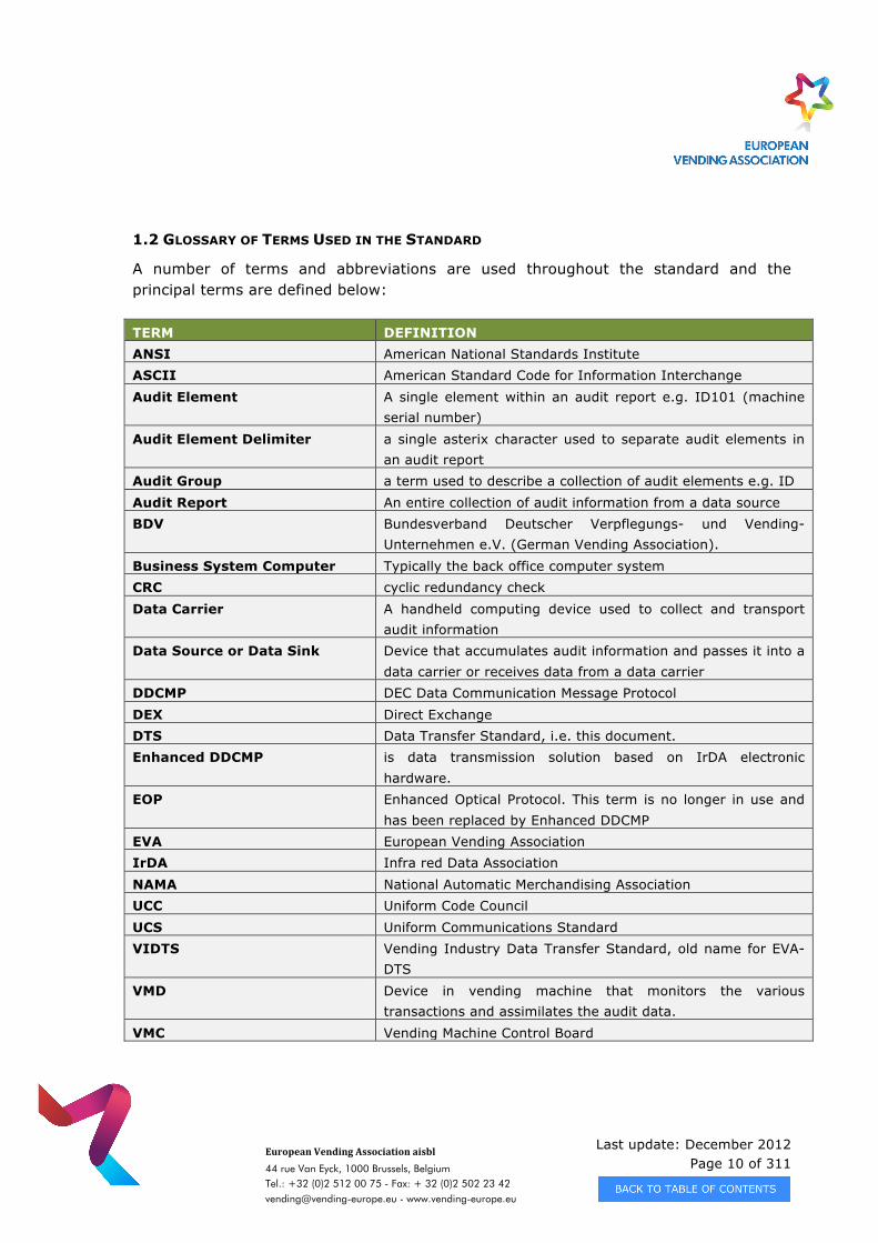
1.2 GLOSSARY OF TERMS USED IN THE STANDARD
A number of terms and abbreviations are used throughout the standard and the principal terms are defined below: TERM DEFINITION ANSI American National Standards Institute ASCII American Standard Code for Information Interchange Audit Element A single element within an audit report e.g. ID101 (machine
serial number) Audit Element Delimiter a single asterix character used to separate audit elements in
an audit report Audit Group a term used to describe a collection of audit elements e.g. ID Audit Report An entire collection of audit information from a data source BDV Bundesverband Deutscher Verpflegungs- und Vending-
Unternehmen e.V. (German Vending Association). Business System Computer Typically the back office computer system CRC cyclic redundancy check Data Carrier A handheld computing device used to collect and transport
audit information Data Source or Data Sink Device that accumulates audit information and passes it into a
data carrier or receives data from a data carrier DDCMP DEC Data Communication Message Protocol DEX Direct Exchange DTS Data Transfer Standard, i.e. this document. Enhanced DDCMP is data transmission solution based on IrDA electronic
hardware. EOP Enhanced Optical Protocol. This term is no longer in use and
has been replaced by Enhanced DDCMP EVA European Vending Association IrDA Infra red Data Association NAMA National Automatic Merchandising Association UCC Uniform Code Council UCS Uniform Communications Standard VIDTS Vending Industry Data Transfer Standard, old name for EVA-
DTS VMD Device in vending machine that monitors the various
transactions and assimilates the audit data. VMC Vending Machine Control Board
Last update: December 2012 Page 11 of 311
European Vending Association aisbl
44 rue Van Eyck, 1000 Brussels, Belgium Tel.: +32 (0)2 512 00 75 - Fax: + 32 (0)2 502 23 42 [email protected] - www.vending-europe.eu
1.3 EVOLUTION OF THE STANDARD
The standard has evolved over several years. Originally a standard was developed and published by the German Vending Association, the BDV. The work was undertaken at
the same time as the American Association, NAMA, was also seeking to develop a standard for data transfer. The definitions of the data elements were mutually agreed. Different physical means for the connection between system elements and the protocol
for the transmission of data were chosen.
Typically, US manufacturers and operators have chosen a data transmission solution based on the DEX/UCS data exchange protocol and a physical connection through a ¼ inch jack plug. However, it may be in the future that developers may wish to use the
DEX/UCS data exchange protocol via the IrDA infra red physical layer.
European applications have been specified to use the Enhanced DDCMP protocol and an optical interface. It is also possible to implement the Enhanced DDCMP Protocol with ¼
inch jack plug physical link.
The original BDV document for DDCMP was called BDV002, but the VIDTS was a complete rewrite of the entire way of doing auditing. Based on the Uniform Code
Council (UCC) DEX/ UCS standard, the vending industry adopted this data format as a means of transferring information between devices. The US adopted the ANSI x3.28
transport layer and physical 1/4" hardwired interface as specified by the existing DEX/UCS standard from the UCC.
Note: The earlier versions of the standard up to Version 4.1 described both the original DDCMP based optical interface and latterly an enhanced optical protocol, also based on DDCMP but with the higher baud rate potential of the IrDA hardware. In version 5.0.
the Optical Interface (formally called EOP) was re-named Enhanced DDCMP.
Implementers of EVA- DTS in data carriers should take account of the requirement to transfer data to and from existing data sources/sinks that might have been based on
the original optical link. Reference should be made to version 4.1 of the standard which is reproduced on the CD containing version 6.1.
Version 6.1. simplifies the handling of discounts and surcharges by simply using the new PA7 elements instead of PA2 and LA elements. Consequently the recommended list
was shortened
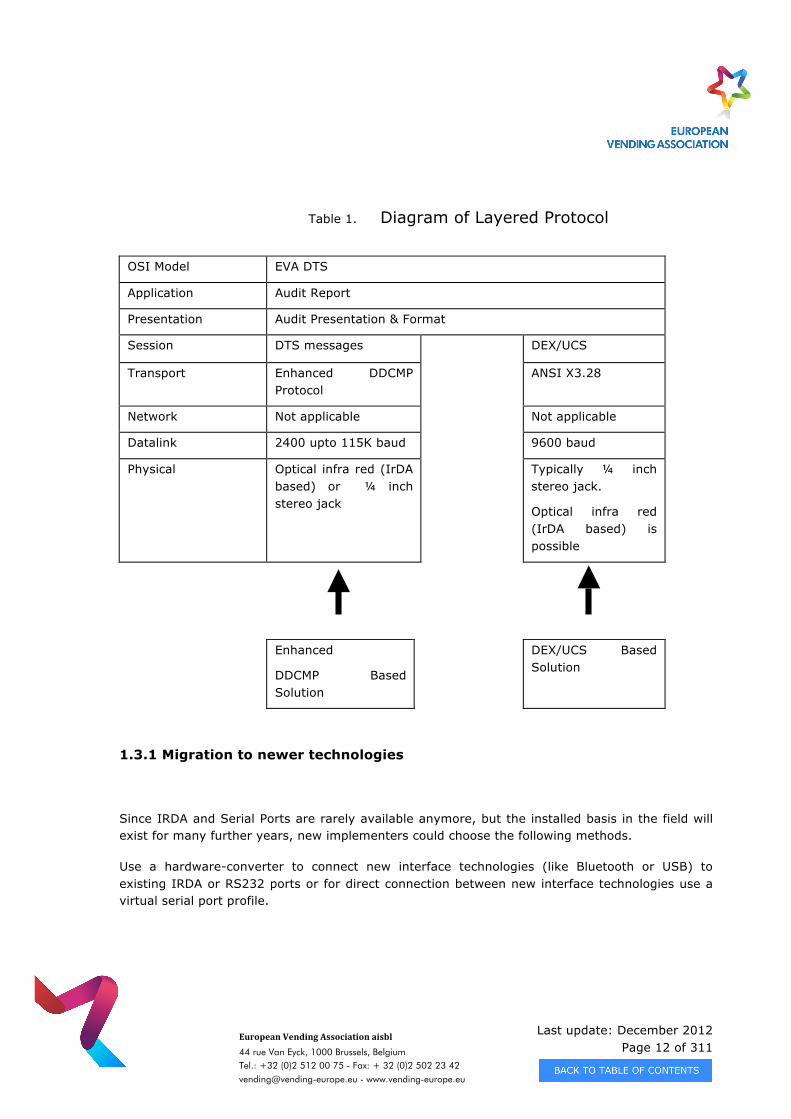
The standard can be described by reference to the OSI 7-layer model.
Table 1 shows relevant layers of the standard and the elements in the DEX/UCS based and Enhanced DDCMP based solutions.
Last update: December 2012 Page 12 of 311
European Vending Association aisbl
44 rue Van Eyck, 1000 Brussels, Belgium Tel.: +32 (0)2 512 00 75 - Fax: + 32 (0)2 502 23 42 [email protected] - www.vending-europe.eu
Table 1. Diagram of Layered Protocol
OSI Model EVA DTS
Application Audit Report
Presentation Audit Presentation & Format
Session DTS messages DEX/UCS
Transport Enhanced DDCMP Protocol
ANSI X3.28
Network Not applicable Not applicable
Datalink 2400 upto 115K baud 9600 baud
Physical Optical infra red (IrDA based) or ¼ inch stereo jack
Typically ¼ inch stereo jack.
Optical infra red (IrDA based) is possible
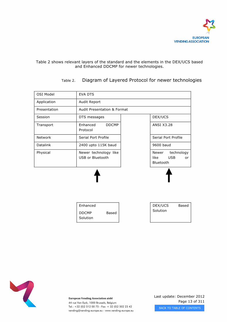
1.3.1 Migration to newer technologies
Since IRDA and Serial Ports are rarely available anymore, but the installed basis in the field will exist for many further years, new implementers could choose the following methods.
Use a hardware-converter to connect new interface technologies (like Bluetooth or USB) to existing IRDA or RS232 ports or for direct connection between new interface technologies use a virtual serial port profile.
Enhanced
DDCMP Based Solution
DEX/UCS Based Solution
Last update: December 2012 Page 13 of 311
European Vending Association aisbl
44 rue Van Eyck, 1000 Brussels, Belgium Tel.: +32 (0)2 512 00 75 - Fax: + 32 (0)2 502 23 42 [email protected] - www.vending-europe.eu
Table 2 shows relevant layers of the standard and the elements in the DEX/UCS based and Enhanced DDCMP for newer technologies.
Table 2. Diagram of Layered Protocol for newer technologies
OSI Model EVA DTS
Application Audit Report
Presentation Audit Presentation & Format
Session DTS messages DEX/UCS
Transport Enhanced DDCMP Protocol
ANSI X3.28
Network Serial Port Profile Serial Port Profile
Datalink 2400 upto 115K baud 9600 baud
Physical Newer technology like USB or Bluetooth
Newer technology like USB or Bluetooth
Enhanced
DDCMP Based Solution
DEX/UCS Based Solution
Last update: December 2012 Page 14 of 311
European Vending Association aisbl
44 rue Van Eyck, 1000 Brussels, Belgium Tel.: +32 (0)2 512 00 75 - Fax: + 32 (0)2 502 23 42 [email protected] - www.vending-europe.eu
1.4 APPLICATION OF THE STANDARD
Version 6.1.1 of EVA-DTS seeks to encourage a wider application of the standard by simplifying the task of potential implementers. It is aimed to achieve this by guiding the implementers of new applications to the essential elements of the total system, which is
of relevance to them.
Table 2 outlines the relevant chapters for specific applications.
European Vending Association aisbl
44 rue Van Eyck, 1000 Brussels, Belgium • Tel.: +32 (0)2 512 00 75 – Fax: + 32 (0)2 502 23 42 • [email protected] • www.vending-europe.eu
VAT: BE 0420 516 576 • Account number: 310-0912858-77 • Swift: BBRU BE BB 100 • IBAN: BE 80 310 091 28 58 77
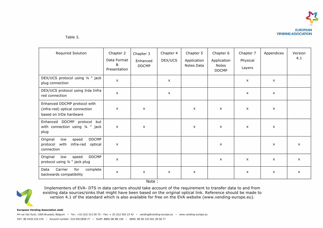
Table 3.
Required Solution Chapter 2
Data Format &
Presentation
Chapter 3
Enhanced DDCMP
Chapter 4
DEX/UCS
Chapter 5
Application Notes Data
Chapter 6
Application Notes
DDCMP
Chapter 7
Physical
Layers
Appendices Version 4.1
DEX/UCS protocol using ¼ “ jack plug connection
x x x x
DEX/UCS protocol using Irda Infra red connection
x x x x
Enhanced DDCMP protocol with (infra-red) optical connection based on IrDa hardware
x x x x x x
Enhanced DDCMP protocol but with connection using ¼ “ jack plug
x x x x x x
Original low speed DDCMP protocol with infra-red optical connection
x x x x
Original low speed DDCMP protocol using ¼ “ jack plug
x x x x x
Data Carrier for complete backwards compatibility
x x x x
x x x
Note :
Implementers of EVA- DTS in data carriers should take account of the requirement to transfer data to and from existing data sources/sinks that might have been based on the original optical link. Reference should be made to
version 4.1 of the standard which is also available for free on the EVA website (www.vending-europe.eu).
Last update: December 2012 Page 16 of 311
European Vending Association aisbl
44 rue Van Eyck, 1000 Brussels, Belgium Tel.: +32 (0)2 512 00 75 - Fax: + 32 (0)2 502 23 42 [email protected] - www.vending-europe.eu
CHAPTER 2 - DATA FORMAT AND PRESENTATION
2.1 REPORT
2.1.1 Definition of a Report
There are two types of reports:
• Audit Report: Information stored in a vending machine device (VMD1) which is transferred via a data carrier to a business system computer. This information can either be transaction type data and/or event data.
• Configuration Report: Information which may be generated in a business system computer and transferred to a vending machine device via a data carrier. In some instances the configuration report can be generated in the data carrier itself. In either case, the configuration report typically modifies the operating parameters of the VMD. Also, the configuration report can send a command to the VMD to perform a specific function, i.e., RESET interval data or RESET an event. Note 1 - A VMD is a device in a vending machine that monitors the various transactions and assimilates the audit data. Examples include vending machine control boards, VMC,coin mechanisms, cashless devices, audit devices, etc.
2.1.2 Syntax of a Report
The Audit and Configuration Reports are composed of a file consisting of several ASCII based data segments terminated with a CRLF (Carriage Return – Line Feed). Each data segment is composed of a similar group of individual data elements separated by an asterisk (*) delimiter. Because the data is all in ASCII, the entire report is “humanly readable”; however, the audit data is typically translated into more business/accounting type reports by the business system computer.
It should be noted that two different protocols (DEX/UCS and DDCMP) are used to transfer the reports between the vending machine device, the data carrier, and the business system computer. These protocols are defined in other chapters of the Data Transfer Standard.
Last update: December 2012 Page 17 of 311
European Vending Association aisbl
44 rue Van Eyck, 1000 Brussels, Belgium Tel.: +32 (0)2 512 00 75 - Fax: + 32 (0)2 502 23 42 [email protected] - www.vending-europe.eu
Regardless of the protocol, the information and syntax of the report is exactly the same per below:
<Application header> Mandatory (see paragraph 2.4)
<Transaction Set header> Mandatory (see paragraph 2.4)
<data segment 1> As Required
<data segment 2> As Required
<data segment 3> As Required
<…>
<data segment n> As Required
<Record Integrity Check> Mandatory (see paragraph 2.4)
<Transaction Set trailer> Mandatory (see paragraph 2.4)
<Application trailer> Mandatory (see paragraph 2.4)
The following sections detail the “makeup” of the data segments and the mandatory headers, trailers, and record integrity check.
2.2 DATA SEGMENTS
2.2.1 Definition of A Data Segment
Data Segments are composed of a group of similar function data elements. These elements are not sent individually, but instead are combined into a single line which has
a block identifier at the start of the line, delimiters between each element, and a carriage return / line feed (cr lf) at the end. The block identifier is a 3 or 4 character
code which identifies the type of data elements following. The individual data elements are separated by an asterisk (*) delimeter.
Last update: December 2012 Page 18 of 311
European Vending Association aisbl
44 rue Van Eyck, 1000 Brussels, Belgium Tel.: +32 (0)2 512 00 75 - Fax: + 32 (0)2 502 23 42 [email protected] - www.vending-europe.eu
2.2.2 Syntax of A Data Segment
<block identifier>*<data element 01>*<data element 02>*<data element 03>*…*<data element n>cr lf
Where:
· <block identifier> defines the data group, it is comprised of two characters and one or two numbers. An example would be:
VA1 or CA10 · The block identifier is followed by a delimiter (asterisk '*'). · <data element nn> A data element is a numeric value or an alphanumeric string. · All characters sent within the Data Segments must be the lower, printable ASCII
characters (20h to 7Eh) plus the Carriage Return (0Dh) and Line Feed (0Ah).
· If more than one element (<data element 01> to <data element nn) is included, the elements are separated by a delimiter (asterisk '*'). The position of the elements in the data segment are referred to using the block identifier and the element number. An example would be:
VA1*VA101*VA102*VA103*VA104 or CA10*CA1001*CA1002 · After the last data element on a line there are carriage return / line feed characters
defining the end of each data segment (cr lf). · Some data segments having the same block identifier may be repeated for different
values of the data elements. The first data element following the block identifier uniquely identifies the data segment. An example would be:
PA1*PA101*PA102*PA103crlf where PA101 = “SEL1” PA1*PA101*PA102*PA103crlf where PA101 = “SEL 2” PA1*PA101*PA102*PA103crlf where PA101 = “SEL 3” · Some data segments having the same block identifier may be repeated for different
values of the data elements and also contain subsequent repeated data segments. The first data element following the lowest numbered block identifier uniquely identifies the data segment and its subsequent data segments. An example would be:
PA1*PA101*PA102*PA103crlf where PA101 = “SEL 1” PA5*PA501*PA502*PA503crlf PA7*PA701*PA702*PA703*PA704*PA705*PA706*PA707*PA708crlf PA1*PA101*PA102*PA103crlf where PA101 = “SEL 2” PA5*PA501*PA502*PA503crlf PA7*PA701*PA702*PA703*PA704*PA705*PA706*PA707*PA708crlf PA1*PA101*PA102*PA103crlf where PA101 = “SEL 3” PA5*PA501*PA502*PA503crlf PA7*PA701*PA702*PA703*PA704*PA705*PA706*PA707*PA708crlf · If data elements are not available, they can be omitted and only the asterisk
delimiter needs to be sent. i.e. ** or *CRLF indicates an element is not available. An example would be:
ID1*ID101*ID102****ID106crlf
Last update: December 2012 Page 19 of 311
European Vending Association aisbl
44 rue Van Eyck, 1000 Brussels, Belgium Tel.: +32 (0)2 512 00 75 - Fax: + 32 (0)2 502 23 42 [email protected] - www.vending-europe.eu
2.2.3 Examples of Actual Data Segments
Below are examples of actual data segments using actual data elements.
Table 1.
Example Data Segments Description
ID1*VMC123crlf Data element ID101 (machine serial number) is VMC123
ID1*VMC123*TYPE3Scrlf Data element ID101 (machine serial number) is VMC123
Data element ID102 (machine model number) is TYPE3S
ID1*VMC123**5678crlf Data element ID101 (machine serial number) is VMC123
Data element ID102 (machine model number) is not included
Data element ID103 (machine build standard) is 5678
ID1*VMC123**5678***CAN
MACHINE 45crlf
Data element ID101 (machine serial number) is VMC123
Data element ID102 (machine model number) is not included
Data element ID103 (machine build standard) is 5678
Data element ID106 (machine asset number) is CAN MACHINE 45
PA1*1*25crlf
PA1*2*35crlf
Repeated group where PA101 is the selection number, PA102 is the price
Selection 1 has a price of 25, and selection 2 has a price of 35.
PA1*1*25crlf
PA7*1*CA*0*25*109crlf
PA1*2*35crlf
PA7*2*CA*0*35*345crlf
Repeated group where lines containing repeated block identifiers have their data elements defined by preceding lines
PA101 is the selection number, PA102 is the price,
PA705 is the number of sales since initialisation
Selection 1 has a price of 25 and 109 items have been vended of that type. Selection 2 has a price of 35 and 345 items have
been vended of that type.
Last update: December 2012 Page 20 of 311
European Vending Association aisbl
44 rue Van Eyck, 1000 Brussels, Belgium Tel.: +32 (0)2 512 00 75 - Fax: + 32 (0)2 502 23 42 [email protected] - www.vending-europe.eu
2.3 DATA ELEMENTS
2.3.1 Definition of a Data Element
A data element holds a piece of audit or configuration information and can be of various types. Each one of the data elements is defined in the Data Dictionary appendix of the
Data Transfer Standard.
The syntax of reports is described below. Examples would be:
PA102 Product Price held in vending machine
PC102 Product Price to be set in vending machine
ID106 Machine Asset Number of vending machine
IC106 Machine Asset Number to be set in vending machine
2.3.2 Data Element Format
› 2.3.2.1 Type
Data elements consist of different types of information as listed below. The Data Dictionary identifies the type of element with a two character code.
<alphanumeric> AN
<numeric> N0, N1, N2, etc.
<currency> Nc
<date> DT
<time> TM
<identifier> ID
<command> CD
Where:
• <alphanumeric> is an element that can contain only the printable characters with the exception of the asterisk (*) since it is used as data element delimiters. By using a printable character as a pre and post identifier (i.e., the symbol for a control character, ^) the alpha-numeric equivalent of the HEX value should be sent for these characters.
Last update: December 2012 Page 21 of 311
European Vending Association aisbl
44 rue Van Eyck, 1000 Brussels, Belgium Tel.: +32 (0)2 512 00 75 - Fax: + 32 (0)2 502 23 42 [email protected] - www.vending-europe.eu
Below are several examples: * (asterisk) ^2A^ CR (carriage return) ^0D^ LF (line feed) ^0A^ (First Upper 128) ^80^ ^ (control symbol) ^5E^ • <numeric> is an element in which the number has an implied decimal point and is
identified as N0, N1, N2, etc. The 0, 1, 2, etc. identifies the number of digits to the right of the decimal point. Note that an integer is represented as N0. Again, the decimal point is implied, it is not transmitted.
• <currency> is an element in which the value has an implied decimal point. It is identified as Nc. Unless otherwise specified, the number of digits to the right of the decimal point are defaulted to 2. This can be overridden by a value described in the ID401 data element. Again, the decimal point is implied, it is not transmitted.
• <date>is a six or eight digit numeric field of the format YYMMDD (year, year, month, month, day, day) or YYYYMMDD (year, year, year, year, month, month, day, day). It is identified as DT.
• <time> is a four or six digit numeric field based on the 24 hour clock of the format HHMM (hour,hour,minute,minute) or HHMMSS (hour,hour,minute, minute,second,second). It is identified as TM.
• <identifier> is an element specific to the Headers and Trailers for identifying unique parameters. It is identified as ID.
• <command> is an element that is used to instruct a VMD to perform a specific function (i.e., RESET audit data) or set a mode (i.e., SAVE audit data). It is identified as CD.
› 2.3.2.2 Length
The Data Dictionary also provides information as to the minimum and maximum length of characters within an element. These are listed as xx/yy where xx is the minimum
and yy is the maximum. An example would be 01/08 which indicates that the minimum element length is 1 character and the maximum is 8 characters.
Last update: December 2012 Page 22 of 311
European Vending Association aisbl
44 rue Van Eyck, 1000 Brussels, Belgium Tel.: +32 (0)2 512 00 75 - Fax: + 32 (0)2 502 23 42 [email protected] - www.vending-europe.eu
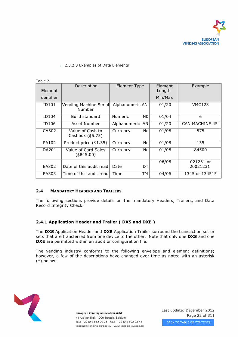
› 2.3.2.3 Examples of Data Elements
Table 2.
Element
dentifier
Description Element Type Element Length
Min/Max
Example
ID101 Vending Machine Serial Number
Alphanumeric AN 01/20 VMC123
ID104 Build standard Numeric N0 01/04 6
ID106 Asset Number Alphanumeric AN 01/20 CAN MACHINE 45
CA302 Value of Cash to Cashbox ($5.75)
Currency Nc 01/08 575
PA102 Product price ($1.35) Currency Nc 01/08 135
DA201 Value of Card Sales ($845.00)
Currency Nc 01/08 84500
EA302 Date of this audit read Date DT 06/08 021231 or
20021231
EA303 Time of this audit read Time TM 04/06 1345 or 134515
2.4 MANDATORY HEADERS AND TRAILERS
The following sections provide details on the mandatory Headers, Trailers, and Data Record Integrity Check.
2.4.1 Application Header and Trailer ( DXS and DXE )
The DXS Application Header and DXE Application Trailer surround the transaction set or sets that are transferred from one device to the other. Note that only one DXS and one DXE are permitted within an audit or configuration file.
The vending industry conforms to the following envelope and element definitions; however, a few of the descriptions have changed over time as noted with an asterisk (*) below:
Last update: December 2012 Page 23 of 311
European Vending Association aisbl
44 rue Van Eyck, 1000 Brussels, Belgium Tel.: +32 (0)2 512 00 75 - Fax: + 32 (0)2 502 23 42 [email protected] - www.vending-europe.eu
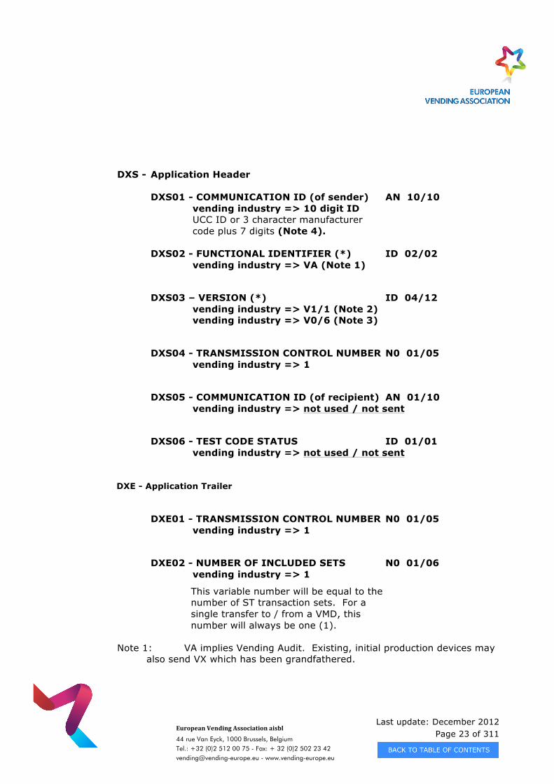
DXS - Application Header
DXS01 - COMMUNICATION ID (of sender) AN 10/10 vending industry => 10 digit ID UCC ID or 3 character manufacturer code plus 7 digits (Note 4).
DXS02 - FUNCTIONAL IDENTIFIER (*) ID 02/02
vending industry => VA (Note 1)
DXS03 – VERSION (*) ID 04/12 vending industry => V1/1 (Note 2) vending industry => V0/6 (Note 3)
DXS04 - TRANSMISSION CONTROL NUMBER N0 01/05 vending industry => 1
DXS05 - COMMUNICATION ID (of recipient) AN 01/10 vending industry => not used / not sent
DXS06 - TEST CODE STATUS ID 01/01 vending industry => not used / not sent
DXE - Application Trailer
DXE01 - TRANSMISSION CONTROL NUMBER N0 01/05
vending industry => 1
DXE02 - NUMBER OF INCLUDED SETS N0 01/06 vending industry => 1
This variable number will be equal to the number of ST transaction sets. For a single transfer to / from a VMD, this number will always be one (1).
Note 1: VA implies Vending Audit. Existing, initial production devices may also send VX which has been grandfathered.
Last update: December 2012 Page 24 of 311
European Vending Association aisbl
44 rue Van Eyck, 1000 Brussels, Belgium Tel.: +32 (0)2 512 00 75 - Fax: + 32 (0)2 502 23 42 [email protected] - www.vending-europe.eu
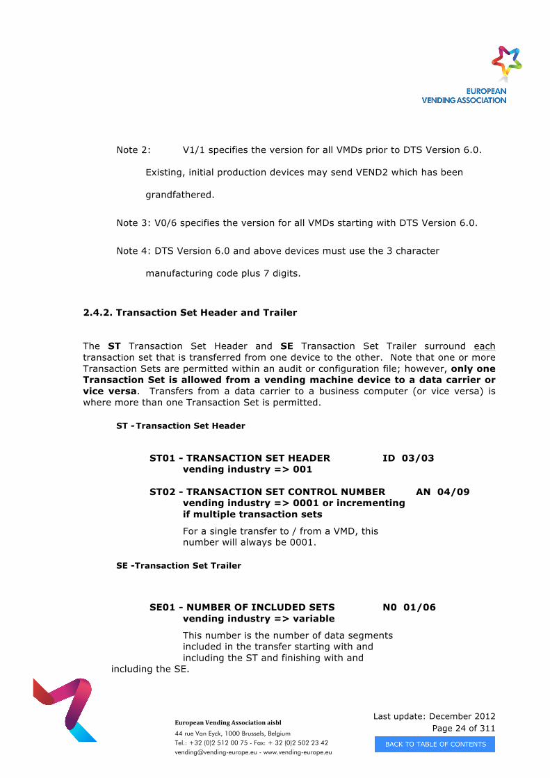
Note 2: V1/1 specifies the version for all VMDs prior to DTS Version 6.0.
Existing, initial production devices may send VEND2 which has been
grandfathered.
Note 3: V0/6 specifies the version for all VMDs starting with DTS Version 6.0.
Note 4: DTS Version 6.0 and above devices must use the 3 character
manufacturing code plus 7 digits.
2.4.2. Transaction Set Header and Trailer
The ST Transaction Set Header and SE Transaction Set Trailer surround each transaction set that is transferred from one device to the other. Note that one or more Transaction Sets are permitted within an audit or configuration file; however, only one Transaction Set is allowed from a vending machine device to a data carrier or vice versa. Transfers from a data carrier to a business computer (or vice versa) is where more than one Transaction Set is permitted.
ST - Transaction Set Header
ST01 - TRANSACTION SET HEADER ID 03/03 vending industry => 001
ST02 - TRANSACTION SET CONTROL NUMBER AN 04/09
vending industry => 0001 or incrementing if multiple transaction sets
For a single transfer to / from a VMD, this number will always be 0001.
SE -Transaction Set Trailer
SE01 - NUMBER OF INCLUDED SETS N0 01/06 vending industry => variable
This number is the number of data segments included in the transfer starting with and including the ST and finishing with and
including the SE.
Last update: December 2012 Page 25 of 311
European Vending Association aisbl
44 rue Van Eyck, 1000 Brussels, Belgium Tel.: +32 (0)2 512 00 75 - Fax: + 32 (0)2 502 23 42 [email protected] - www.vending-europe.eu
SE02 - TRANSACTION SET CONTROL NUMBER AN 04/09
vending industry => 0001 or incrementing if multiple transaction sets
For a single transfer to / from a VMD, this number will always be 0001.
2.4.3. Data Record Integrity Check
Each transaction set data record has a CRC-16 based integrity check associated with it. This is based on the DEX/UCS Delivery/Return Base Records (Transaction Sets) as described in the UCS/DSD Implementation Guide Section VII.
G85 - Record Integrity Check
G8501 - INTEGRITY CHECK VALUE AN 04/04 vending industry => as defined
The G85 Record Integrity Check is used to verify the contents of the complete transaction set from the beginning of the ST data segment to the end of the data prior to the G85 data segment. If the contents of the data are altered in any way the calculated G85 Record Integrity Check will be different signifying that part of the transaction set has been altered or corrupted.
All VMDs sending audit data must transfer the G85 data segment prior to sending the SE - Transaction Set Trailer. There is no requirement that the Data Carrier (DC) check the G85 Record Integrity Check; however, it is recommended.
All Data Carriers sending configuration data must transfer the G85 data segment prior to sending the SE - Transaction Set Trailer. There is no requirement that the VMD check the G85 Record Integrity Check; however, it is recommended.
The G85 data segment is sent as four ASCII characters (0-9, A, B, C, D, E, F) indicating the four nibbles of a CRC-16 calculation. Since the CRC-16 is based on two bytes, the
most significant byte is sent first and the least significant byte is sent second. In
Last update: December 2012 Page 26 of 311
European Vending Association aisbl
44 rue Van Eyck, 1000 Brussels, Belgium Tel.: +32 (0)2 512 00 75 - Fax: + 32 (0)2 502 23 42 [email protected] - www.vending-europe.eu
essence, if the CRC-16 had a value of 1234h, the G85 Record Integrity Check would be sent as G85*1234. Early implementations of much equipment may have this order reversed, it is a reasonable test to check both orderings for systems prior to DTS version 6.0.
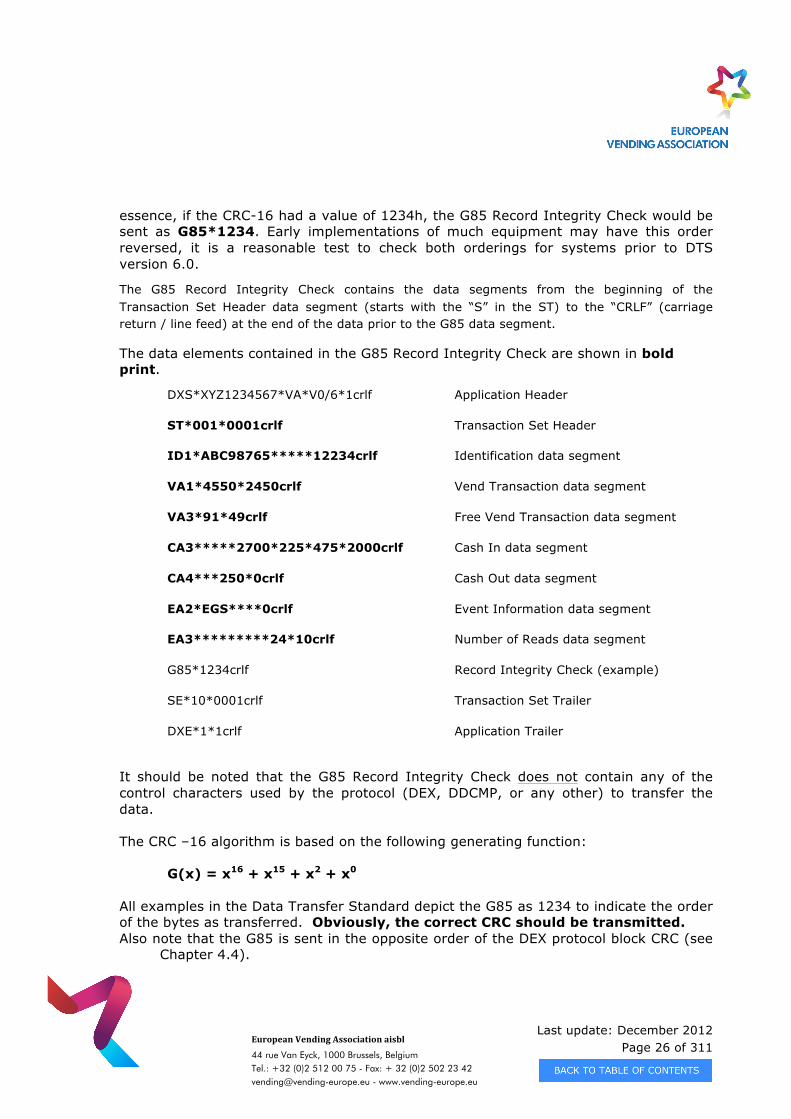
The G85 Record Integrity Check contains the data segments from the beginning of the Transaction Set Header data segment (starts with the “S” in the ST) to the “CRLF” (carriage return / line feed) at the end of the data prior to the G85 data segment.
The data elements contained in the G85 Record Integrity Check are shown in bold print.
DXS*XYZ1234567*VA*V0/6*1crlf Application Header
ST*001*0001crlf Transaction Set Header
ID1*ABC98765*****12234crlf Identification data segment
VA1*4550*2450crlf Vend Transaction data segment
VA3*91*49crlf Free Vend Transaction data segment
CA3*****2700*225*475*2000crlf Cash In data segment
CA4***250*0crlf Cash Out data segment
EA2*EGS****0crlf Event Information data segment
EA3*********24*10crlf Number of Reads data segment
G85*1234crlf Record Integrity Check (example)
SE*10*0001crlf Transaction Set Trailer
DXE*1*1crlf Application Trailer
It should be noted that the G85 Record Integrity Check does not contain any of the control characters used by the protocol (DEX, DDCMP, or any other) to transfer the data. The CRC –16 algorithm is based on the following generating function:
G(x) = x16 + x15 + x2 + x0 All examples in the Data Transfer Standard depict the G85 as 1234 to indicate the order of the bytes as transferred. Obviously, the correct CRC should be transmitted. Also note that the G85 is sent in the opposite order of the DEX protocol block CRC (see
Chapter 4.4).
Last update: December 2012 Page 27 of 311
European Vending Association aisbl
44 rue Van Eyck, 1000 Brussels, Belgium Tel.: +32 (0)2 512 00 75 - Fax: + 32 (0)2 502 23 42 [email protected] - www.vending-europe.eu
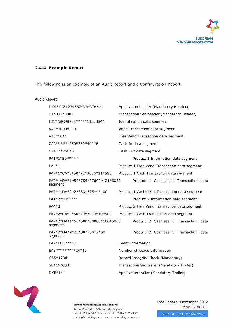
2.4.4 Example Report
The following is an example of an Audit Report and a Configuration Report.
Audit Report:
DXS*XYZ1234567*VA*V0/6*1 Application header (Mandatory Header)
ST*001*0001 Transaction Set header (Mandatory Header)
ID1*ABC98765*****11223344 Identification data segment
VA1*1000*200 Vend Transaction data segment
VA3*50*1 Free Vend Transaction data segment
CA3*****1250*250*400*6 Cash In data segment
CA4***250*0 Cash Out data segment
PA1*1*50***** Product 1 Information data segment
PA4*1 Product 1 Free Vend Transaction data segment
PA7*1*CA*0*50*72*3600*11*550 Product 1 Cash Transaction data segment
PA7*1*DA*1*50*756*37800*121*6050 Product 1 Cashless 1 Transaction data segment
PA7*1*DA*2*25*33*825*4*100 Product 1 Cashless 1 Transaction data segment
PA1*2*50***** Product 2 Information data segment
PA4*0 Product 2 Free Vend Transaction data segment
PA7*2*CA*0*50*40*2000*10*500 Product 2 Cash Transaction data segment
PA7*2*DA*1*50*600*30000*100*5000 Product 2 Cashless 1 Transaction data segment
PA7*2*DA*2*25*30*750*2*50 Product 2 Cashless 1 Transaction data segment
EA2*EGS****1 Event Information
EA3*********24*10 Number of Reads Information
G85*1234 Record Integrity Check (Mandatory)
SE*16*0001 Transaction Set trailer (Mandatory Trailer)
DXE*1*1 Application trailer (Mandatory Trailer)
Last update: December 2012 Page 28 of 311
European Vending Association aisbl
44 rue Van Eyck, 1000 Brussels, Belgium Tel.: +32 (0)2 512 00 75 - Fax: + 32 (0)2 502 23 42 [email protected] - www.vending-europe.eu
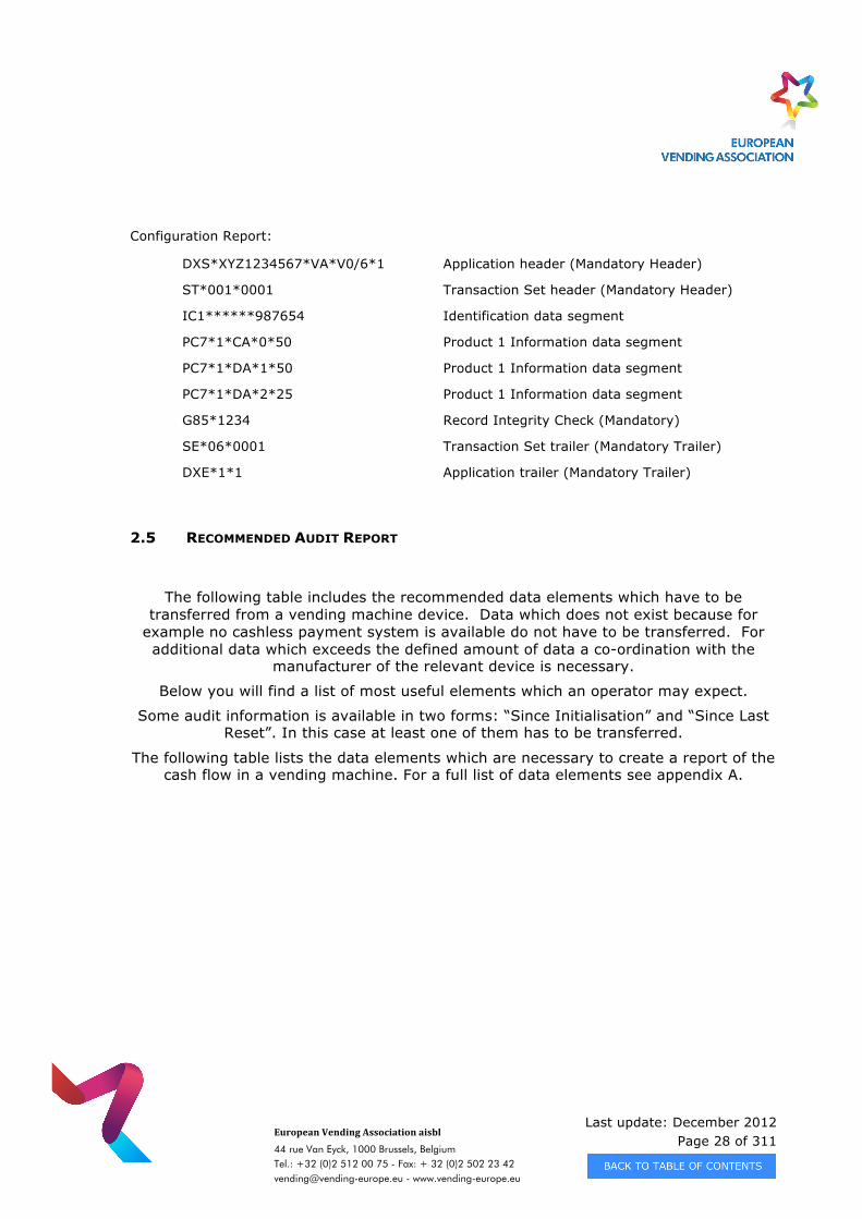
Configuration Report:
DXS*XYZ1234567*VA*V0/6*1 Application header (Mandatory Header)
ST*001*0001 Transaction Set header (Mandatory Header)
IC1******987654 Identification data segment
PC7*1*CA*0*50 Product 1 Information data segment
PC7*1*DA*1*50 Product 1 Information data segment
PC7*1*DA*2*25 Product 1 Information data segment
G85*1234 Record Integrity Check (Mandatory)
SE*06*0001 Transaction Set trailer (Mandatory Trailer)
DXE*1*1 Application trailer (Mandatory Trailer)
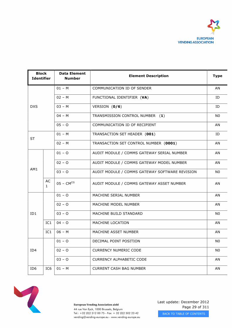
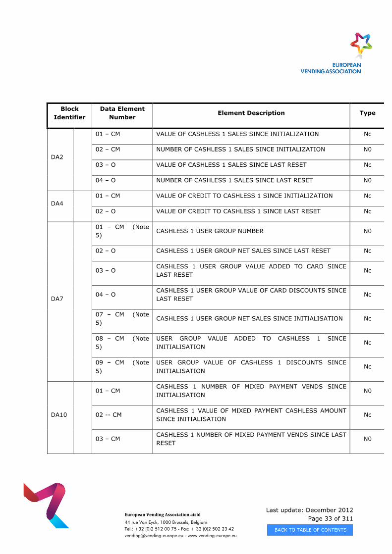
2.5 RECOMMENDED AUDIT REPORT
The following table includes the recommended data elements which have to be transferred from a vending machine device. Data which does not exist because for
example no cashless payment system is available do not have to be transferred. For additional data which exceeds the defined amount of data a co-ordination with the
manufacturer of the relevant device is necessary.
Below you will find a list of most useful elements which an operator may expect.
Some audit information is available in two forms: “Since Initialisation” and “Since Last Reset”. In this case at least one of them has to be transferred.
The following table lists the data elements which are necessary to create a report of the cash flow in a vending machine. For a full list of data elements see appendix A.
Last update: December 2012 Page 29 of 311
European Vending Association aisbl
44 rue Van Eyck, 1000 Brussels, Belgium Tel.: +32 (0)2 512 00 75 - Fax: + 32 (0)2 502 23 42 [email protected] - www.vending-europe.eu
Block Identifier
Data Element Number
Element Description Type
DXS
01 – M COMMUNICATION ID OF SENDER AN
02 – M FUNCTIONAL IDENTIFIER (VA) ID
03 – M VERSION (0/6) ID
04 – M TRANSMISSION CONTROL NUMBER (1) N0
05 – O COMMUNICATION ID OF RECIPIENT AN
ST 01 – M TRANSACTION SET HEADER (001) ID
02 – M TRANSACTION SET CONTROL NUMBER (0001) AN
AM1
01 – O AUDIT MODULE / COMMS GATEWAY SERIAL NUMBER AN
02 – O AUDIT MODULE / COMMS GATEWAY MODEL NUMBER AN
03 – O AUDIT MODULE / COMMS GATEWAY SOFTWARE REVISION N0
AC1
05 – CMCG AUDIT MODULE / COMMS GATEWAY ASSET NUMBER AN
ID1
01 – O MACHINE SERIAL NUMBER AN
02 – O MACHINE MODEL NUMBER AN
03 – O MACHINE BUILD STANDARD N0
IC1 04 – O MACHINE LOCATION AN
IC1 06 – M MACHINE ASSET NUMBER AN
ID4
01 – O DECIMAL POINT POSITION N0
02 – O CURRENCY NUMERIC CODE N0
03 – O CURRENCY ALPHABETIC CODE AN
ID6 IC6 01 – M CURRENT CASH BAG NUMBER AN
Last update: December 2012 Page 30 of 311
European Vending Association aisbl
44 rue Van Eyck, 1000 Brussels, Belgium Tel.: +32 (0)2 512 00 75 - Fax: + 32 (0)2 502 23 42 [email protected] - www.vending-europe.eu
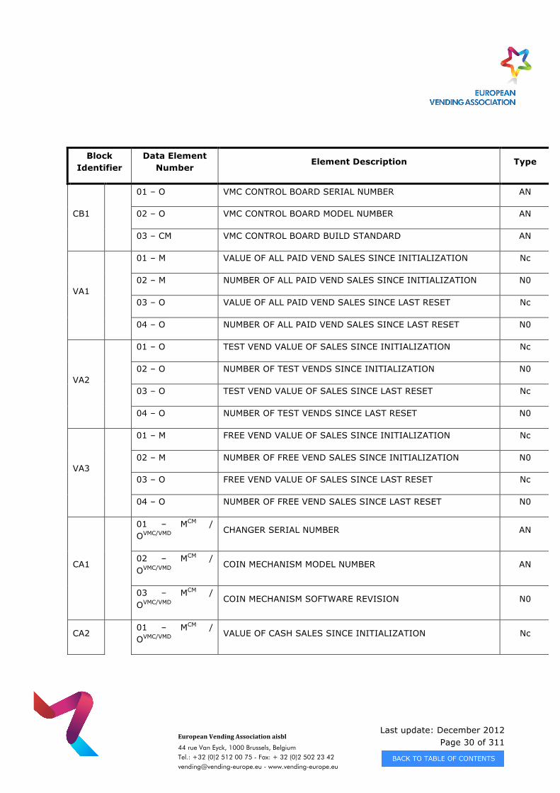
Block Identifier
Data Element Number
Element Description Type
CB1
01 – O VMC CONTROL BOARD SERIAL NUMBER AN
02 – O VMC CONTROL BOARD MODEL NUMBER AN
03 – CM VMC CONTROL BOARD BUILD STANDARD AN
VA1
01 – M VALUE OF ALL PAID VEND SALES SINCE INITIALIZATION Nc
02 – M NUMBER OF ALL PAID VEND SALES SINCE INITIALIZATION N0
03 – O VALUE OF ALL PAID VEND SALES SINCE LAST RESET Nc
04 – O NUMBER OF ALL PAID VEND SALES SINCE LAST RESET N0
VA2
01 – O TEST VEND VALUE OF SALES SINCE INITIALIZATION Nc
02 – O NUMBER OF TEST VENDS SINCE INITIALIZATION N0
03 – O TEST VEND VALUE OF SALES SINCE LAST RESET Nc
04 – O NUMBER OF TEST VENDS SINCE LAST RESET N0
VA3
01 – M FREE VEND VALUE OF SALES SINCE INITIALIZATION Nc
02 – M NUMBER OF FREE VEND SALES SINCE INITIALIZATION N0
03 – O FREE VEND VALUE OF SALES SINCE LAST RESET Nc
04 – O NUMBER OF FREE VEND SALES SINCE LAST RESET N0
CA1
01 – MCM / OVMC/VMD
CHANGER SERIAL NUMBER AN
02 – MCM / OVMC/VMD
COIN MECHANISM MODEL NUMBER AN
03 – MCM / OVMC/VMD
COIN MECHANISM SOFTWARE REVISION N0
CA2 01 – MCM / OVMC/VMD
VALUE OF CASH SALES SINCE INITIALIZATION Nc
Last update: December 2012 Page 31 of 311
European Vending Association aisbl
44 rue Van Eyck, 1000 Brussels, Belgium Tel.: +32 (0)2 512 00 75 - Fax: + 32 (0)2 502 23 42 [email protected] - www.vending-europe.eu
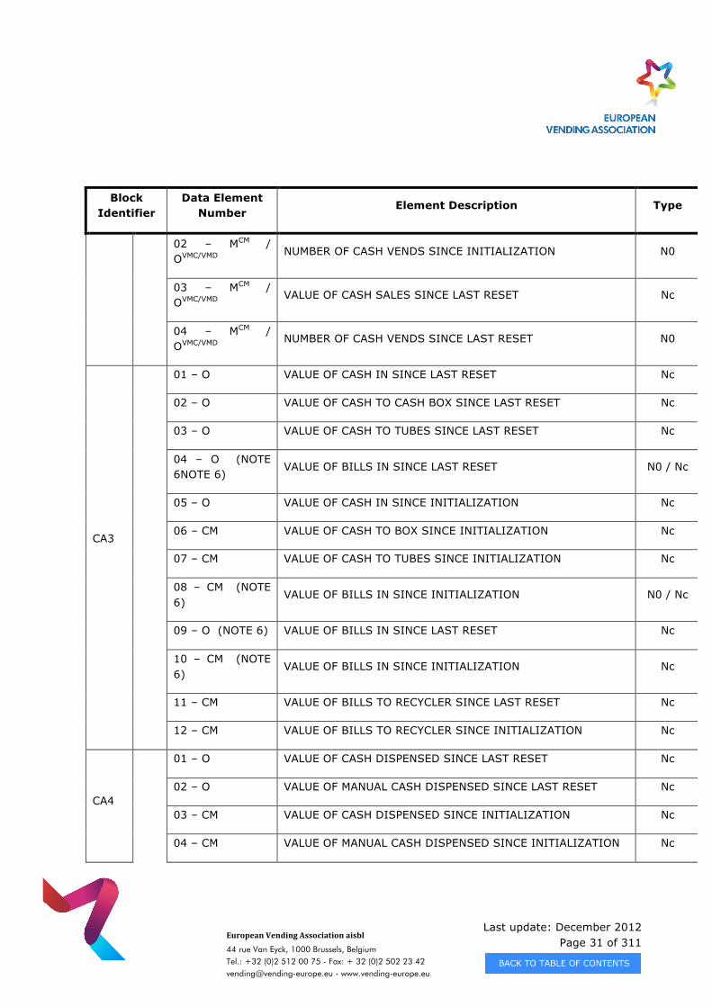
Block Identifier
Data Element Number
Element Description Type
02 – MCM / OVMC/VMD
NUMBER OF CASH VENDS SINCE INITIALIZATION N0
03 – MCM / OVMC/VMD
VALUE OF CASH SALES SINCE LAST RESET Nc
04 – MCM / OVMC/VMD
NUMBER OF CASH VENDS SINCE LAST RESET N0
CA3
01 – O VALUE OF CASH IN SINCE LAST RESET Nc
02 – O VALUE OF CASH TO CASH BOX SINCE LAST RESET Nc
03 – O VALUE OF CASH TO TUBES SINCE LAST RESET Nc
04 – O (NOTE 6NOTE 6)
VALUE OF BILLS IN SINCE LAST RESET N0 / Nc
05 – O VALUE OF CASH IN SINCE INITIALIZATION Nc
06 – CM VALUE OF CASH TO BOX SINCE INITIALIZATION Nc
07 – CM VALUE OF CASH TO TUBES SINCE INITIALIZATION Nc
08 – CM (NOTE 6)
VALUE OF BILLS IN SINCE INITIALIZATION N0 / Nc
09 – O (NOTE 6) VALUE OF BILLS IN SINCE LAST RESET Nc
10 – CM (NOTE 6)
VALUE OF BILLS IN SINCE INITIALIZATION Nc
11 – CM VALUE OF BILLS TO RECYCLER SINCE LAST RESET Nc
12 – CM VALUE OF BILLS TO RECYCLER SINCE INITIALIZATION Nc
CA4
01 – O VALUE OF CASH DISPENSED SINCE LAST RESET Nc
02 – O VALUE OF MANUAL CASH DISPENSED SINCE LAST RESET Nc
03 – CM VALUE OF CASH DISPENSED SINCE INITIALIZATION Nc
04 – CM VALUE OF MANUAL CASH DISPENSED SINCE INITIALIZATION Nc
Last update: December 2012 Page 32 of 311
European Vending Association aisbl
44 rue Van Eyck, 1000 Brussels, Belgium Tel.: +32 (0)2 512 00 75 - Fax: + 32 (0)2 502 23 42 [email protected] - www.vending-europe.eu
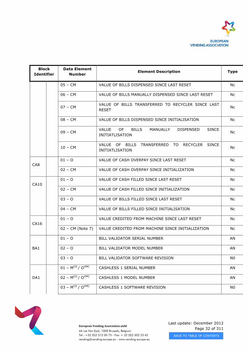
Block Identifier
Data Element Number
Element Description Type
05 – CM VALUE OF BILLS DISPENSED SINCE LAST RESET Nc
06 – CM VALUE OF BILLS MANUALLY DISPENSED SINCE LAST RESET Nc
07 – CM VALUE OF BILLS TRANSFERRED TO RECYCLER SINCE LAST RESET
Nc
08 – CM VALUE OF BILLS DISPENSED SINCE INITIALISATION Nc
09 – CM VALUE OF BILLS MANUALLY DISPENSED SINCE INITIATLISATION
Nc
10 – CM VALUE OF BILLS TRANSFERRED TO RECYCLER SINCE INITIATLISATION
Nc
CA8 01 – O VALUE OF CASH OVERPAY SINCE LAST RESET Nc
02 – CM VALUE OF CASH OVERPAY SINCE INITIALIZATION Nc
CA10 01 – O VALUE OF CASH FILLED SINCE LAST RESET Nc
02 – CM VALUE OF CASH FILLED SINCE INITIALIZATION Nc
03 – O VALUE OF BILLS FILLED SINCE LAST RESET Nc
04 – CM VALUE OF BILLS FILLED SINCE INITIALISATION Nc
CA16 01 – O VALUE CREDITED FROM MACHINE SINCE LAST RESET Nc
02 – CM (Note 7) VALUE CREDITED FROM MACHINE SINCE INITIALIZATION Nc
BA1
01 – O BILL VALIDATOR SERIAL NUMBER AN
02 – O BILL VALIDATOR MODEL NUMBER AN
03 – O BILL VALIDATOR SOFTWARE REVISION N0
DA1
01 – MCD / OVMC CASHLESS 1 SERIAL NUMBER AN
02 – MCD / OVMC CASHLESS 1 MODEL NUMBER AN
03 – MCD / OVMC CASHLESS 1 SOFTWARE REVISION N0
Last update: December 2012 Page 33 of 311
European Vending Association aisbl
44 rue Van Eyck, 1000 Brussels, Belgium Tel.: +32 (0)2 512 00 75 - Fax: + 32 (0)2 502 23 42 [email protected] - www.vending-europe.eu
Block Identifier
Data Element Number
Element Description Type
DA2
01 – CM VALUE OF CASHLESS 1 SALES SINCE INITIALIZATION Nc
02 – CM NUMBER OF CASHLESS 1 SALES SINCE INITIALIZATION N0
03 – O VALUE OF CASHLESS 1 SALES SINCE LAST RESET Nc
04 – O NUMBER OF CASHLESS 1 SALES SINCE LAST RESET N0
DA4 01 – CM VALUE OF CREDIT TO CASHLESS 1 SINCE INITIALIZATION Nc
02 – O VALUE OF CREDIT TO CASHLESS 1 SINCE LAST RESET Nc
DA7
01 – CM (Note 5)
CASHLESS 1 USER GROUP NUMBER N0
02 – O CASHLESS 1 USER GROUP NET SALES SINCE LAST RESET Nc
03 – O CASHLESS 1 USER GROUP VALUE ADDED TO CARD SINCE LAST RESET
Nc
04 – O CASHLESS 1 USER GROUP VALUE OF CARD DISCOUNTS SINCE LAST RESET
Nc
07 – CM (Note 5)
CASHLESS 1 USER GROUP NET SALES SINCE INITIALISATION Nc
08 – CM (Note 5)
USER GROUP VALUE ADDED TO CASHLESS 1 SINCE INITIALISATION
Nc
09 – CM (Note 5)
USER GROUP VALUE OF CASHLESS 1 DISCOUNTS SINCE INITIALISATION
Nc
DA10
01 – CM
CASHLESS 1 NUMBER OF MIXED PAYMENT VENDS SINCE INITIALISATION
N0
02 -- CM CASHLESS 1 VALUE OF MIXED PAYMENT CASHLESS AMOUNT SINCE INITIALISATION
Nc
03 – CM CASHLESS 1 NUMBER OF MIXED PAYMENT VENDS SINCE LAST RESET
N0
Last update: December 2012 Page 34 of 311
European Vending Association aisbl
44 rue Van Eyck, 1000 Brussels, Belgium Tel.: +32 (0)2 512 00 75 - Fax: + 32 (0)2 502 23 42 [email protected] - www.vending-europe.eu
Block Identifier
Data Element Number
Element Description Type
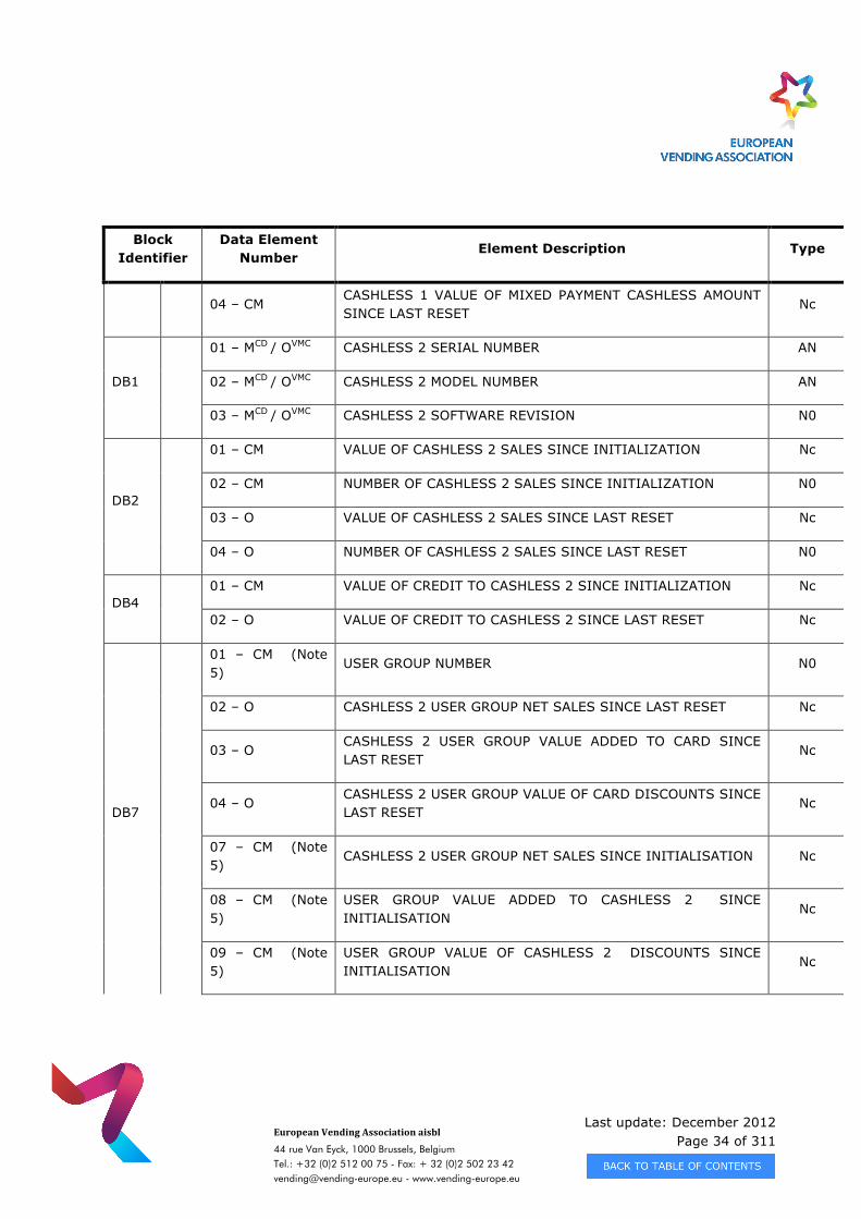
04 – CM CASHLESS 1 VALUE OF MIXED PAYMENT CASHLESS AMOUNT SINCE LAST RESET
Nc
DB1
01 – MCD / OVMC CASHLESS 2 SERIAL NUMBER AN
02 – MCD / OVMC CASHLESS 2 MODEL NUMBER AN
03 – MCD / OVMC CASHLESS 2 SOFTWARE REVISION N0
DB2
01 – CM VALUE OF CASHLESS 2 SALES SINCE INITIALIZATION Nc
02 – CM NUMBER OF CASHLESS 2 SALES SINCE INITIALIZATION N0
03 – O VALUE OF CASHLESS 2 SALES SINCE LAST RESET Nc
04 – O NUMBER OF CASHLESS 2 SALES SINCE LAST RESET N0
DB4 01 – CM VALUE OF CREDIT TO CASHLESS 2 SINCE INITIALIZATION Nc
02 – O VALUE OF CREDIT TO CASHLESS 2 SINCE LAST RESET Nc
DB7
01 – CM (Note 5)
USER GROUP NUMBER N0
02 – O CASHLESS 2 USER GROUP NET SALES SINCE LAST RESET Nc
03 – O CASHLESS 2 USER GROUP VALUE ADDED TO CARD SINCE LAST RESET
Nc
04 – O CASHLESS 2 USER GROUP VALUE OF CARD DISCOUNTS SINCE LAST RESET
Nc
07 – CM (Note 5)
CASHLESS 2 USER GROUP NET SALES SINCE INITIALISATION Nc
08 – CM (Note 5)
USER GROUP VALUE ADDED TO CASHLESS 2 SINCE INITIALISATION
Nc
09 – CM (Note 5)
USER GROUP VALUE OF CASHLESS 2 DISCOUNTS SINCE INITIALISATION
Nc
Last update: December 2012 Page 35 of 311
European Vending Association aisbl
44 rue Van Eyck, 1000 Brussels, Belgium Tel.: +32 (0)2 512 00 75 - Fax: + 32 (0)2 502 23 42 [email protected] - www.vending-europe.eu
Block Identifier
Data Element Number
Element Description Type
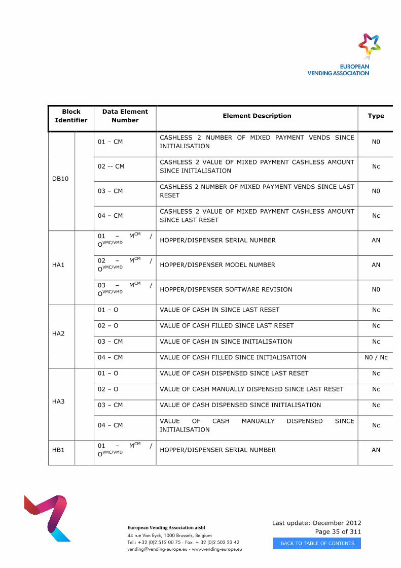
DB10
01 – CM
CASHLESS 2 NUMBER OF MIXED PAYMENT VENDS SINCE INITIALISATION
N0
02 -- CM CASHLESS 2 VALUE OF MIXED PAYMENT CASHLESS AMOUNT SINCE INITIALISATION
Nc
03 – CM CASHLESS 2 NUMBER OF MIXED PAYMENT VENDS SINCE LAST RESET
N0
04 – CM CASHLESS 2 VALUE OF MIXED PAYMENT CASHLESS AMOUNT SINCE LAST RESET
Nc
HA1
01 – MCM / OVMC/VMD
HOPPER/DISPENSER SERIAL NUMBER AN
02 – MCM / OVMC/VMD
HOPPER/DISPENSER MODEL NUMBER AN
03 – MCM / OVMC/VMD
HOPPER/DISPENSER SOFTWARE REVISION N0
HA2
01 – O VALUE OF CASH IN SINCE LAST RESET Nc
02 – O VALUE OF CASH FILLED SINCE LAST RESET Nc
03 – CM VALUE OF CASH IN SINCE INITIALISATION Nc
04 – CM VALUE OF CASH FILLED SINCE INITIALISATION N0 / Nc
HA3
01 – O VALUE OF CASH DISPENSED SINCE LAST RESET Nc
02 – O VALUE OF CASH MANUALLY DISPENSED SINCE LAST RESET Nc
03 – CM VALUE OF CASH DISPENSED SINCE INITIALISATION Nc
04 – CM VALUE OF CASH MANUALLY DISPENSED SINCE INITIALISATION
Nc
HB1 01 – MCM /
OVMC/VMD HOPPER/DISPENSER SERIAL NUMBER AN
Last update: December 2012 Page 36 of 311
European Vending Association aisbl
44 rue Van Eyck, 1000 Brussels, Belgium Tel.: +32 (0)2 512 00 75 - Fax: + 32 (0)2 502 23 42 [email protected] - www.vending-europe.eu
Block Identifier
Data Element Number
Element Description Type
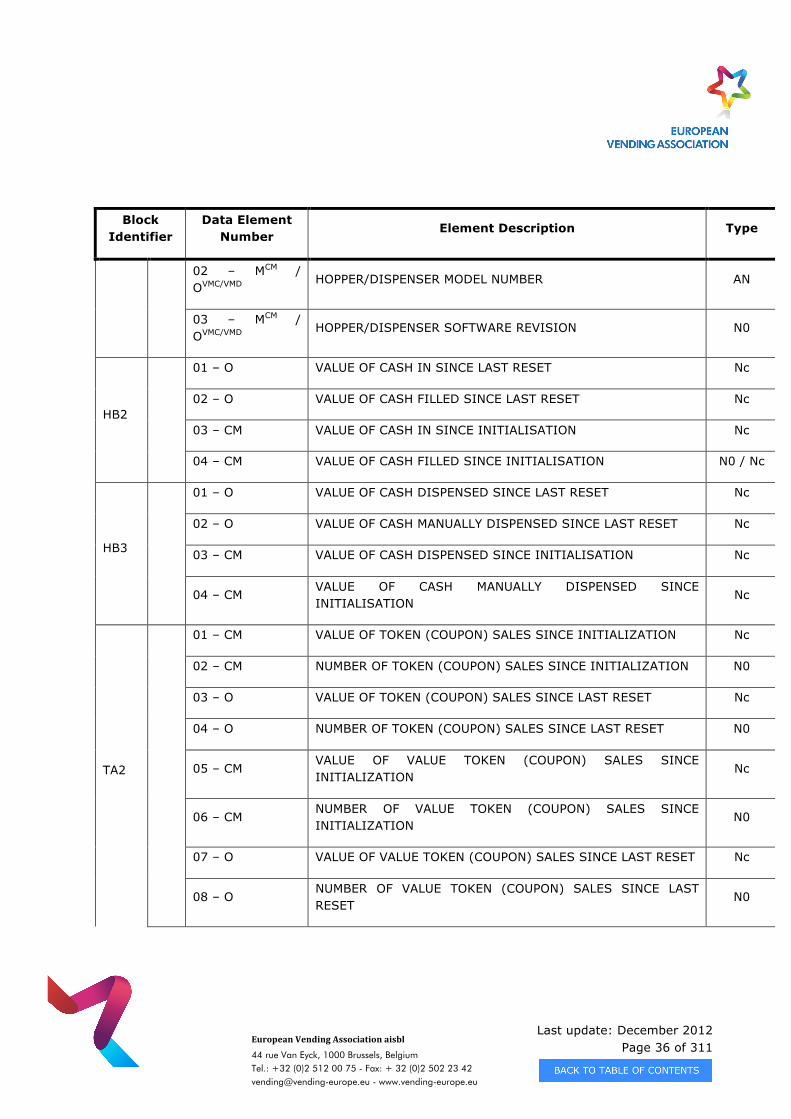
02 – MCM / OVMC/VMD
HOPPER/DISPENSER MODEL NUMBER AN
03 – MCM / OVMC/VMD
HOPPER/DISPENSER SOFTWARE REVISION N0
HB2
01 – O VALUE OF CASH IN SINCE LAST RESET Nc
02 – O VALUE OF CASH FILLED SINCE LAST RESET Nc
03 – CM VALUE OF CASH IN SINCE INITIALISATION Nc
04 – CM VALUE OF CASH FILLED SINCE INITIALISATION N0 / Nc
HB3
01 – O VALUE OF CASH DISPENSED SINCE LAST RESET Nc
02 – O VALUE OF CASH MANUALLY DISPENSED SINCE LAST RESET Nc
03 – CM VALUE OF CASH DISPENSED SINCE INITIALISATION Nc
04 – CM VALUE OF CASH MANUALLY DISPENSED SINCE INITIALISATION
Nc
TA2
01 – CM VALUE OF TOKEN (COUPON) SALES SINCE INITIALIZATION Nc
02 – CM NUMBER OF TOKEN (COUPON) SALES SINCE INITIALIZATION N0
03 – O VALUE OF TOKEN (COUPON) SALES SINCE LAST RESET Nc
04 – O NUMBER OF TOKEN (COUPON) SALES SINCE LAST RESET N0
05 – CM VALUE OF VALUE TOKEN (COUPON) SALES SINCE INITIALIZATION
Nc
06 – CM NUMBER OF VALUE TOKEN (COUPON) SALES SINCE INITIALIZATION
N0
07 – O VALUE OF VALUE TOKEN (COUPON) SALES SINCE LAST RESET Nc
08 – O NUMBER OF VALUE TOKEN (COUPON) SALES SINCE LAST RESET
N0
Last update: December 2012 Page 37 of 311
European Vending Association aisbl
44 rue Van Eyck, 1000 Brussels, Belgium Tel.: +32 (0)2 512 00 75 - Fax: + 32 (0)2 502 23 42 [email protected] - www.vending-europe.eu
Block Identifier
Data Element Number
Element Description Type
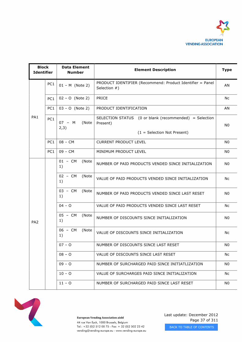
PA1
PC1 01 – M (Note 2) PRODUCT IDENTIFIER (Recommend: Product Identifier = Panel Selection #)
AN
PC1 02 – O (Note 2) PRICE Nc
PC1 03 – O (Note 2) PRODUCT IDENTIFICATION AN
PC1 07 – M (Note 2,3)
SELECTION STATUS (0 or blank (recommended) = Selection Present)
(1 = Selection Not Present)
N0
PC1 08 – CM CURRENT PRODUCT LEVEL N0
PC1 09 – CM MINIMUM PRODUCT LEVEL N0
PA2
01 – CM (Note 1)
NUMBER OF PAID PRODUCTS VENDED SINCE INITIALIZATION N0
02 – CM (Note 1)
VALUE OF PAID PRODUCTS VENDED SINCE INITIALIZATION Nc
03 – CM (Note 1)
NUMBER OF PAID PRODUCTS VENDED SINCE LAST RESET N0
04 – O VALUE OF PAID PRODUCTS VENDED SINCE LAST RESET Nc
05 – CM (Note 1)
NUMBER OF DISCOUNTS SINCE INITIALIZATION N0
06 – CM (Note 1)
VALUE OF DISCOUNTS SINCE INITIALIZATION Nc
07 – O NUMBER OF DISCOUNTS SINCE LAST RESET N0
08 – O VALUE OF DISCOUNTS SINCE LAST RESET Nc
09 – O NUMBER OF SURCHARGED PAID SINCE INITIATLIZATION N0
10 – O VALUE OF SURCHARGES PAID SINCE INITIALIZATION Nc
11 – O NUMBER OF SURCHARGED PAID SINCE LAST RESET N0
Last update: December 2012 Page 38 of 311
European Vending Association aisbl
44 rue Van Eyck, 1000 Brussels, Belgium Tel.: +32 (0)2 512 00 75 - Fax: + 32 (0)2 502 23 42 [email protected] - www.vending-europe.eu
Block Identifier
Data Element Number
Element Description Type
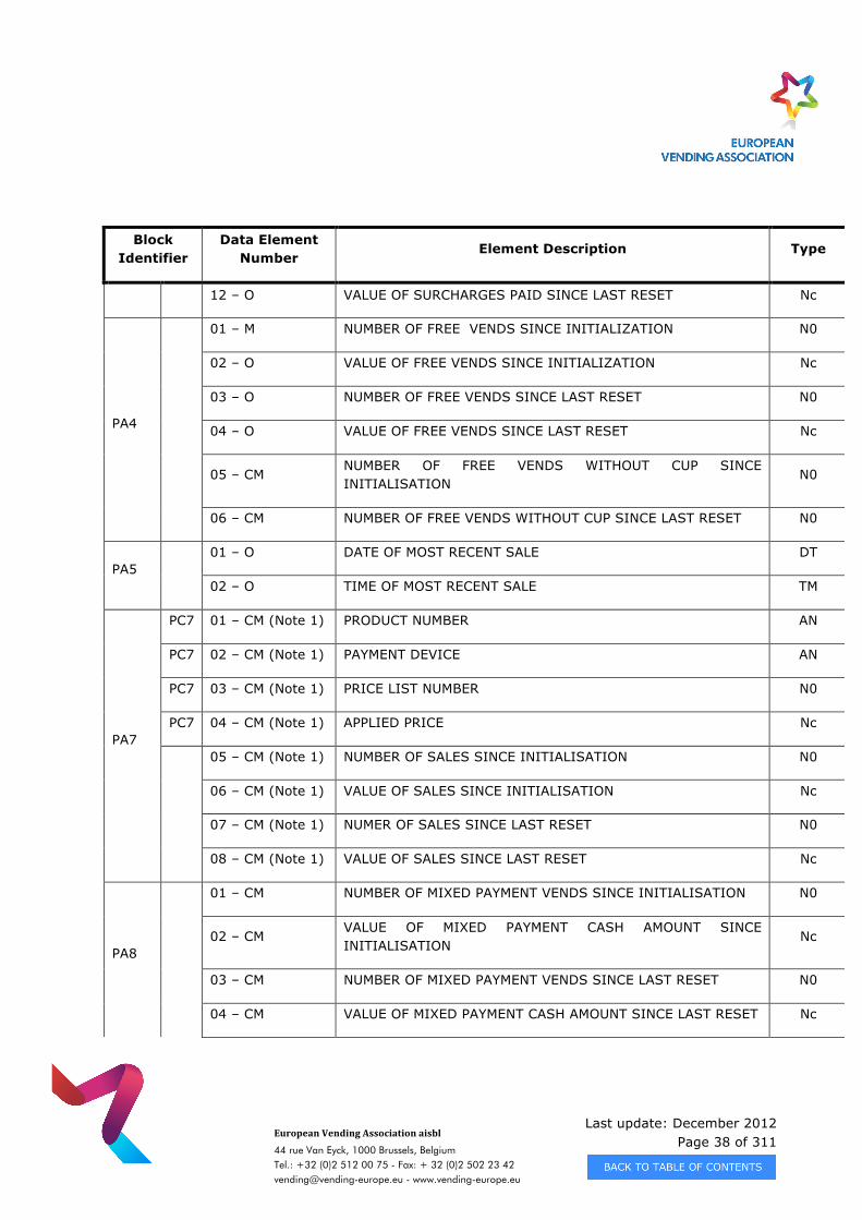
12 – O VALUE OF SURCHARGES PAID SINCE LAST RESET Nc
PA4
01 – M NUMBER OF FREE VENDS SINCE INITIALIZATION N0
02 – O VALUE OF FREE VENDS SINCE INITIALIZATION Nc
03 – O NUMBER OF FREE VENDS SINCE LAST RESET N0
04 – O VALUE OF FREE VENDS SINCE LAST RESET Nc
05 – CM NUMBER OF FREE VENDS WITHOUT CUP SINCE INITIALISATION
N0
06 – CM NUMBER OF FREE VENDS WITHOUT CUP SINCE LAST RESET N0
PA5 01 – O DATE OF MOST RECENT SALE DT
02 – O TIME OF MOST RECENT SALE TM
PA7
PC7 01 – CM (Note 1) PRODUCT NUMBER AN
PC7 02 – CM (Note 1) PAYMENT DEVICE AN
PC7 03 – CM (Note 1) PRICE LIST NUMBER N0
PC7 04 – CM (Note 1) APPLIED PRICE Nc
05 – CM (Note 1) NUMBER OF SALES SINCE INITIALISATION N0
06 – CM (Note 1) VALUE OF SALES SINCE INITIALISATION Nc
07 – CM (Note 1) NUMER OF SALES SINCE LAST RESET N0
08 – CM (Note 1) VALUE OF SALES SINCE LAST RESET Nc
PA8
01 – CM NUMBER OF MIXED PAYMENT VENDS SINCE INITIALISATION N0
02 – CM VALUE OF MIXED PAYMENT CASH AMOUNT SINCE INITIALISATION
Nc
03 – CM NUMBER OF MIXED PAYMENT VENDS SINCE LAST RESET N0
04 – CM VALUE OF MIXED PAYMENT CASH AMOUNT SINCE LAST RESET Nc
Last update: December 2012 Page 39 of 311
European Vending Association aisbl
44 rue Van Eyck, 1000 Brussels, Belgium Tel.: +32 (0)2 512 00 75 - Fax: + 32 (0)2 502 23 42 [email protected] - www.vending-europe.eu
Block Identifier
Data Element Number
Element Description Type
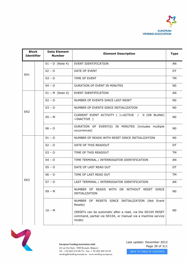
EA1
01 – O (Note 4) EVENT IDENTIFICATION AN
02 – O DATE OF EVENT DT
03 – O TIME OF EVENT TM
04 – O DURATION OF EVENT IN MINUTES N0
EA2
01 – M (Note 4) EVENT IDENTIFICATION AN
02 – O NUMBER OF EVENTS SINCE LAST RESET N0
03 – O NUMBER OF EVENTS SINCE INITIALIZATION N0
05 – M CURRENT EVENT ACTIVITY ( 1=ACTIVE / 0 (OR BLANK) =INACTIVE )
N0
06 – O DURATION OF EVENT(S) IN MINUTES (includes multiple occurrences)
N0
EA3
01 – O NUMBER OF READS WITH RESET SINCE INITIALIZATION N0
02 – O DATE OF THIS READOUT DT
03 – O TIME OF THIS READOUT TM
04 – O TIME TERMINAL / INTERROGATOR IDENTIFICATION AN
05 – O DATE OF LAST READ OUT DT
06 – O TIME OF LAST READ OUT TM
07 – O LAST TERMINAL / INTERROGATOR IDENTIFICATION AN
09 – M NUMBER OF READS WITH OR WITHOUT RESET SINCE INITIALIZATION
N0
10 – M
NUMBER OF RESETS SINCE INITIALIZATION (Not Event Resets)
(RESETs can be automatic after a read, via the SD105 RESET command, partial via SD104, or manual via a machine service mode)
N0
Last update: December 2012 Page 40 of 311
European Vending Association aisbl
44 rue Van Eyck, 1000 Brussels, Belgium Tel.: +32 (0)2 512 00 75 - Fax: + 32 (0)2 502 23 42 [email protected] - www.vending-europe.eu
Block Identifier
Data Element Number
Element Description Type
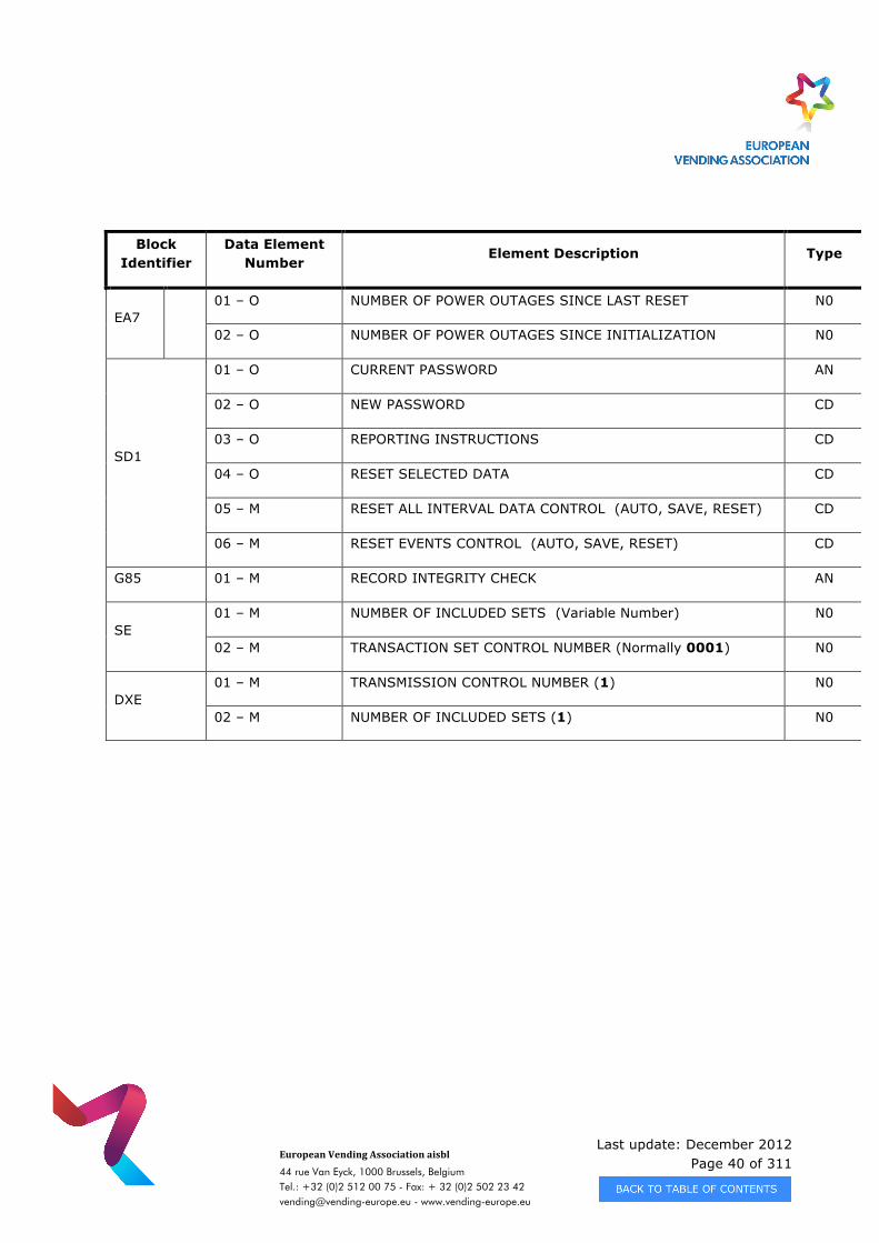
EA7 01 – O NUMBER OF POWER OUTAGES SINCE LAST RESET N0
02 – O NUMBER OF POWER OUTAGES SINCE INITIALIZATION N0
SD1
01 – O CURRENT PASSWORD AN
02 – O NEW PASSWORD CD
03 – O REPORTING INSTRUCTIONS CD
04 – O RESET SELECTED DATA CD
05 – M RESET ALL INTERVAL DATA CONTROL (AUTO, SAVE, RESET) CD
06 – M RESET EVENTS CONTROL (AUTO, SAVE, RESET) CD
G85 01 – M RECORD INTEGRITY CHECK AN
SE 01 – M NUMBER OF INCLUDED SETS (Variable Number) N0
02 – M TRANSACTION SET CONTROL NUMBER (Normally 0001) N0
DXE 01 – M TRANSMISSION CONTROL NUMBER (1) N0
02 – M NUMBER OF INCLUDED SETS (1) N0
Last update: December 2012 Page 41 of 311
European Vending Association aisbl
44 rue Van Eyck, 1000 Brussels, Belgium Tel.: +32 (0)2 512 00 75 - Fax: + 32 (0)2 502 23 42 [email protected] - www.vending-europe.eu
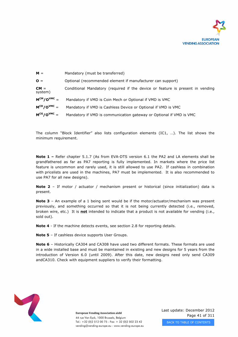
M = Mandatory (must be transferred)
O = Optional (recommended element if manufacturer can support)
CM = Conditional Mandatory (required if the device or feature is present in vending system)
MCM/OVMC = Mandatory if VMD is Coin Mech or Optional if VMD is VMC
MCD/OVMC = Mandatory if VMD is Cashless Device or Optional if VMD is VMC
MCG/OVMC = Mandatory if VMD is communication gateway or Optional if VMD is VMC
The column “Block Identifier” also lists configuration elements (IC1, …). The list shows the minimum requirement.
Note 1 – Refer chapter 5.1.7 (As from EVA-DTS version 6.1 the PA2 and LA elements shall be grandfathered as far as PA7 reporting is fully implemented. In markets where the price list feature is uncommon and rarely used, it is still allowed to use PA2. If cashless in combination with pricelists are used in the machines, PA7 must be implemented. It is also recommended to use PA7 for all new designs).
Note 2 – If motor / actuator / mechanism present or historical (since initialization) data is present.
Note 3 – An example of a 1 being sent would be if the motor/actuator/mechanism was present previously, and something occurred so that it is not being currently detected (i.e., removed, broken wire, etc.) It is not intended to indicate that a product is not available for vending (i.e., sold out).
Note 4 - If the machine detects events, see section 2.8 for reporting details.
Note 5 – If cashless device supports User Groups.
Note 6 – Historically CA304 and CA308 have used two different formats. These formats are used in a wide installed base and must be maintained in existing and new designs for 5 years from the introduction of Version 6.0 (until 2009). After this date, new designs need only send CA309 andCA310. Check with equipment suppliers to verify their formatting.
Last update: December 2012 Page 42 of 311
European Vending Association aisbl
44 rue Van Eyck, 1000 Brussels, Belgium Tel.: +32 (0)2 512 00 75 - Fax: + 32 (0)2 502 23 42 [email protected] - www.vending-europe.eu
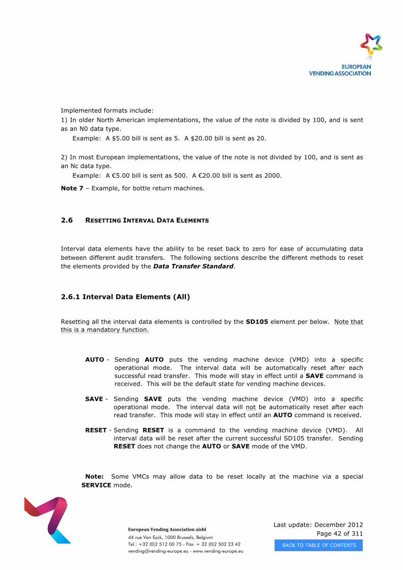
Implemented formats include: 1) In older North American implementations, the value of the note is divided by 100, and is sent as an N0 data type. Example: A $5.00 bill is sent as 5. A $20.00 bill is sent as 20. 2) In most European implementations, the value of the note is not divided by 100, and is sent as an Nc data type. Example: A €5.00 bill is sent as 500. A €20.00 bill is sent as 2000.
Note 7 – Example, for bottle return machines.
2.6 RESETTING INTERVAL DATA ELEMENTS
Interval data elements have the ability to be reset back to zero for ease of accumulating data between different audit transfers. The following sections describe the different methods to reset the elements provided by the Data Transfer Standard.
2.6.1 Interval Data Elements (All)
Resetting all the interval data elements is controlled by the SD105 element per below. Note that this is a mandatory function.
AUTO - Sending AUTO puts the vending machine device (VMD) into a specific operational mode. The interval data will be automatically reset after each successful read transfer. This mode will stay in effect until a SAVE command is received. This will be the default state for vending machine devices.
SAVE - Sending SAVE puts the vending machine device (VMD) into a specific operational mode. The interval data will not be automatically reset after each read transfer. This mode will stay in effect until an AUTO command is received.
RESET - Sending RESET is a command to the vending machine device (VMD). All interval data will be reset after the current successful SD105 transfer. Sending RESET does not change the AUTO or SAVE mode of the VMD.
Note: Some VMCs may allow data to be reset locally at the machine via a special SERVICE mode.
Last update: December 2012 Page 43 of 311
European Vending Association aisbl
44 rue Van Eyck, 1000 Brussels, Belgium Tel.: +32 (0)2 512 00 75 - Fax: + 32 (0)2 502 23 42 [email protected] - www.vending-europe.eu
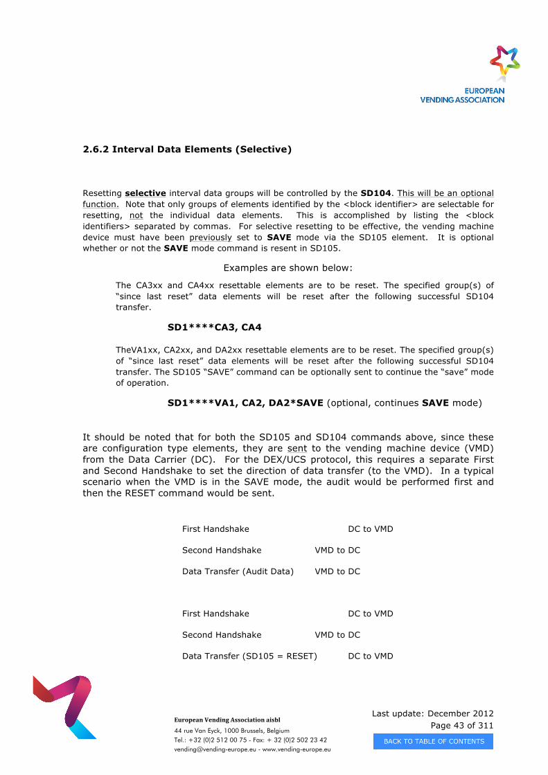
2.6.2 Interval Data Elements (Selective)
Resetting selective interval data groups will be controlled by the SD104. This will be an optional function. Note that only groups of elements identified by the <block identifier> are selectable for resetting, not the individual data elements. This is accomplished by listing the <block identifiers> separated by commas. For selective resetting to be effective, the vending machine device must have been previously set to SAVE mode via the SD105 element. It is optional whether or not the SAVE mode command is resent in SD105.
Examples are shown below:
The CA3xx and CA4xx resettable elements are to be reset. The specified group(s) of “since last reset” data elements will be reset after the following successful SD104 transfer.
SD1****CA3, CA4
TheVA1xx, CA2xx, and DA2xx resettable elements are to be reset. The specified group(s) of “since last reset” data elements will be reset after the following successful SD104 transfer. The SD105 “SAVE” command can be optionally sent to continue the “save” mode of operation.
SD1****VA1, CA2, DA2*SAVE (optional, continues SAVE mode)
It should be noted that for both the SD105 and SD104 commands above, since these are configuration type elements, they are sent to the vending machine device (VMD) from the Data Carrier (DC). For the DEX/UCS protocol, this requires a separate First and Second Handshake to set the direction of data transfer (to the VMD). In a typical scenario when the VMD is in the SAVE mode, the audit would be performed first and then the RESET command would be sent.
First Handshake DC to VMD
Second Handshake VMD to DC
Data Transfer (Audit Data) VMD to DC
First Handshake DC to VMD
Second Handshake VMD to DC
Data Transfer (SD105 = RESET) DC to VMD
Last update: December 2012 Page 44 of 311
European Vending Association aisbl
44 rue Van Eyck, 1000 Brussels, Belgium Tel.: +32 (0)2 512 00 75 - Fax: + 32 (0)2 502 23 42 [email protected] - www.vending-europe.eu
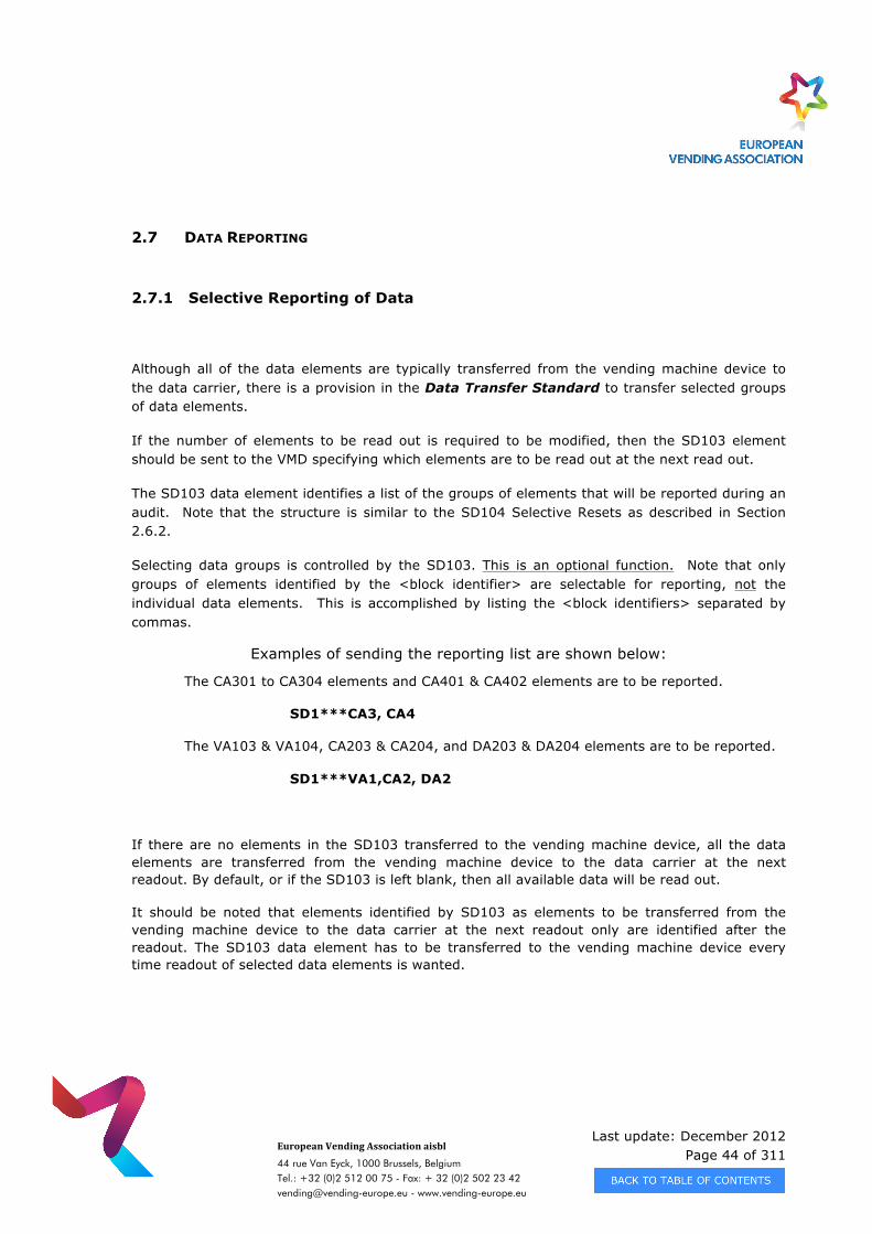
2.7 DATA REPORTING
2.7.1 Selective Reporting of Data
Although all of the data elements are typically transferred from the vending machine device to the data carrier, there is a provision in the Data Transfer Standard to transfer selected groups of data elements.
If the number of elements to be read out is required to be modified, then the SD103 element should be sent to the VMD specifying which elements are to be read out at the next read out.
The SD103 data element identifies a list of the groups of elements that will be reported during an audit. Note that the structure is similar to the SD104 Selective Resets as described in Section 2.6.2.
Selecting data groups is controlled by the SD103. This is an optional function. Note that only groups of elements identified by the <block identifier> are selectable for reporting, not the individual data elements. This is accomplished by listing the <block identifiers> separated by commas.
Examples of sending the reporting list are shown below:
The CA301 to CA304 elements and CA401 & CA402 elements are to be reported.
SD1***CA3, CA4
The VA103 & VA104, CA203 & CA204, and DA203 & DA204 elements are to be reported.
SD1***VA1,CA2, DA2
If there are no elements in the SD103 transferred to the vending machine device, all the data elements are transferred from the vending machine device to the data carrier at the next readout. By default, or if the SD103 is left blank, then all available data will be read out.
It should be noted that elements identified by SD103 as elements to be transferred from the vending machine device to the data carrier at the next readout only are identified after the readout. The SD103 data element has to be transferred to the vending machine device every time readout of selected data elements is wanted.
Last update: December 2012 Page 45 of 311
European Vending Association aisbl
44 rue Van Eyck, 1000 Brussels, Belgium Tel.: +32 (0)2 512 00 75 - Fax: + 32 (0)2 502 23 42 [email protected] - www.vending-europe.eu
2.7.2 Reporting of Data using lists
The recommended Audit Report specified in Section 2.5 is defined as Audit Collection list (List 1).
In DDCMP protocol additional lists are specified as defined in Section 3.6
2.8 EVENT REPORTING INSTRUCTIONS
Events are occurrences in a vending machine device that get stored and reported to the data carrier when an audit is performed. Although events can often be faults in a machine, they also indicate normal functions such as door openings or closings. The EA1 data segment captures the date, time, and duration of the event and the EA2 data segment captures the number of the events.
To minimize the amount of data to be transferred, fault reference codes are sent using a three or four character structured code segmented as follows:
First Letter Second Letter Third Letter & Optional #
E - Equipment Event Unit affected Code Specific Event Code O - Operational Event Operation Affected Code Specific Event Code
Appendix C lists the complete Equipment Events (E based codes) and Operational Events (O based codes).
The following sections describe the operation of the events with respect to reporting and resetting / clearing.
EVENT States
Events will have three states:
State 1 - No Incidence & Not Active – An EVENT is not occurring and is inactive.
This is the normal state of EVENTs, i.e., not happening.
Last update: December 2012 Page 46 of 311
European Vending Association aisbl
44 rue Van Eyck, 1000 Brussels, Belgium Tel.: +32 (0)2 512 00 75 - Fax: + 32 (0)2 502 23 42 [email protected] - www.vending-europe.eu
State 2 - Incidence & Active – An EVENT has occurred and it is currently active.
This is the state of an EVENT that has occurred and has not been repaired or corrected itself.
State 3 - Incidence & Not Active – An EVENT has occurred and is currently inactive.
This is the state of an EVENT that has occurred and has been repaired or corrected itself.
2.8.1 Event Inclusion
An EVENT will only be included in an audit (i.e., the EA201 & EA205 sent) if it is in State 2 or State 3. Historical events (State 1) are not transmitted. In essence, an EVENT is only sent if it occurred since the last transmission and is still active or if it occurred since the last audit and has been repaired or corrected itself.
This allows EVENTs to be detected by the host system regardless of whether or not they are currently active.
2.8.2 Event Resetting / Clearing
EVENTs can only be reset/cleared by the Data Transfer Standard (DEX/UCS or Enhanced DDCMP (eDDCMP) and only if they are in State 3. In essence, an EVENT can only be reset if it is not active, i.e., the EVENT has been fixed at the machine or has corrected itself. This allows all vending machine reportable EVENTs to be logged by the Host System and does not allow an active EVENT to be cleared/reset before a repair is made or it corrects itself.
The SD106 data element operates similar to the SD105. This allows for flexibility in the resetting/clearing of EVENT reporting.
AUTO - Sending AUTO in SD106 puts the vending machine device (VMD) into a specific operational EVENT mode. All State 3 EVENTs will be automatically reset after each successful read transfer. This mode will stay in effect until a SAVE command is received. This will be the default state for vending machine devices.
Last update: December 2012 Page 47 of 311
European Vending Association aisbl
44 rue Van Eyck, 1000 Brussels, Belgium Tel.: +32 (0)2 512 00 75 - Fax: + 32 (0)2 502 23 42 [email protected] - www.vending-europe.eu
SAVE - Sending SAVE in SD106 puts the vending machine device (VMD) into a specific operational EVENT mode. State 3 EVENTs will not be automatically reset after each read transfer. This mode will stay in effect until an AUTO command is received.
RESET - Sending RESET is a command to the vending machine device (VMD). All State 3 EVENTs will be reset after the current successful SD105 transfer. Sending RESET does not change the AUTO or SAVE mode of the VMD.
2.8.3 Event Reporting Examples
The following examples are provided to better understand the EVENT reporting mechanism. Note that the EVENT codes are defined in Appendix C and are highlighted in bold.
Example 1
The following mandatory data elements provide the basic EVENT information required by the host system. This EVENT is in the STATE 2 category.
EA201 indicates EVENT EGS which is defined as Door Open
EA205 indicates that the EVENT EGS is currently active (the door is open)
DXS*XYZ1234567*VA*V0/6*1 Application header (Mandatory Header)
ST*001*0001 Transaction Set header (Mandatory Header)
ID1*ABC98765*****11223344 Identification data segment
VA1*1000*200 Vend Transaction data segment
VA3*50*1 Free Vend Transaction data segment
CA3*****1250*250*400*6 Cash In data segment
CA4***250*0 Cash Out data segment
PA1*1*50***** Product 1 Information data segment
PA4*1 Product 1 Free Vend Transaction data segment
PA7*1*CA*0*50*72*3600*11*550 Product 1 Cash Transaction data segment
Last update: December 2012 Page 48 of 311
European Vending Association aisbl
44 rue Van Eyck, 1000 Brussels, Belgium Tel.: +32 (0)2 512 00 75 - Fax: + 32 (0)2 502 23 42 [email protected] - www.vending-europe.eu
PA7*1*DA*1*50*756*37800*121*6050 Product 1 Cashless 1 Transaction data segment
PA7*1*DA*2*25*33*825*4*100 Product 1 Cashless 1 Transaction data segment
PA1*2*50***** Product 2 Information data segment
PA4*0 Product 2 Free Vend Transaction data segment
PA7*2*CA*0*50*40*2000*10*500 Product 2 Cash Transaction data segment
PA7*2*DA*1*50*600*30000*100*5000 Product 2 Cashless 1 Transaction data segment
PA7*2*DA*2*25*30*750*2*50 Product 2 Cashless 1 Transaction data segment
EA2*EGS****1 Event Information
EA3*********24*10 Number of Reads Information
G85*1234 Record Integrity Check (Mandatory)
SE*16*0001 Transaction Set trailer (Mandatory Trailer)
DXE*1*1 Application trailer (Mandatory Trailer)
Example 2 The example above can be expanded to show additional optional EVENT information. The following data elements provide optional and basic EVENT information required by the host system. This EVENT is in the STATE 3 category.
EA101 indicates EVENT EGS which is defined as Door Open EA102 indicates the EVENT took place on 24 June, 2002 EA103 indicates the EVENT took place at 14:30 EA104 indicates the EVENT has occurred for 52 minutes EA201 indicates EVENT EGS which is defined as Door Open EA202 indicates the EVENT has occurred 4 times since the last audit EA203 indicates the EVENT has occurred 36 time since initialization EA205 indicates that the EVENT EGS is currently inactive (the door is closed)
DXS*XYZ1234567*VA*V0/6*1 Application header (Mandatory Header)
ST*001*0001 Transaction Set header (Mandatory Header)
ID1*ABC98765*****11223344 Identification data segment
VA1*1000*200 Vend Transaction data segment
VA3*50*1 Free Vend Transaction data segment
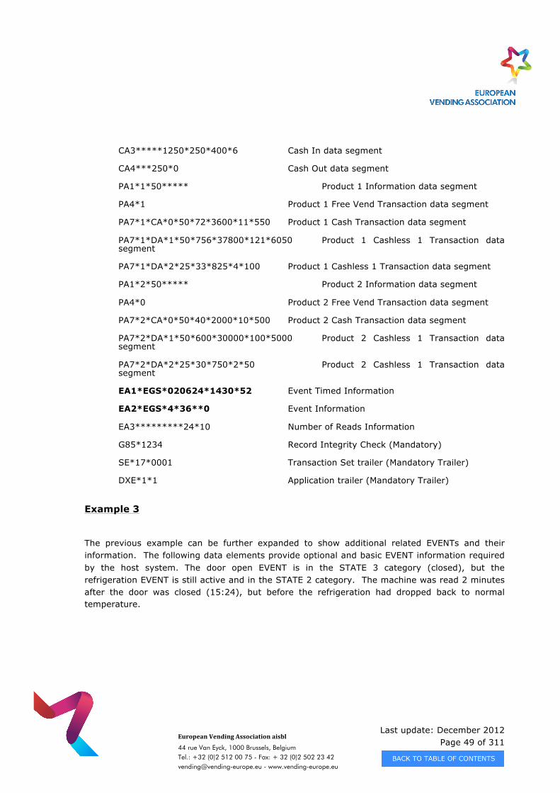
Last update: December 2012 Page 49 of 311
European Vending Association aisbl
44 rue Van Eyck, 1000 Brussels, Belgium Tel.: +32 (0)2 512 00 75 - Fax: + 32 (0)2 502 23 42 [email protected] - www.vending-europe.eu
CA3*****1250*250*400*6 Cash In data segment
CA4***250*0 Cash Out data segment
PA1*1*50***** Product 1 Information data segment
PA4*1 Product 1 Free Vend Transaction data segment
PA7*1*CA*0*50*72*3600*11*550 Product 1 Cash Transaction data segment
PA7*1*DA*1*50*756*37800*121*6050 Product 1 Cashless 1 Transaction data segment
PA7*1*DA*2*25*33*825*4*100 Product 1 Cashless 1 Transaction data segment
PA1*2*50***** Product 2 Information data segment
PA4*0 Product 2 Free Vend Transaction data segment
PA7*2*CA*0*50*40*2000*10*500 Product 2 Cash Transaction data segment
PA7*2*DA*1*50*600*30000*100*5000 Product 2 Cashless 1 Transaction data segment
PA7*2*DA*2*25*30*750*2*50 Product 2 Cashless 1 Transaction data segment
EA1*EGS*020624*1430*52 Event Timed Information
EA2*EGS*4*36**0 Event Information
EA3*********24*10 Number of Reads Information
G85*1234 Record Integrity Check (Mandatory)
SE*17*0001 Transaction Set trailer (Mandatory Trailer)
DXE*1*1 Application trailer (Mandatory Trailer)
Example 3
The previous example can be further expanded to show additional related EVENTs and their information. The following data elements provide optional and basic EVENT information required by the host system. The door open EVENT is in the STATE 3 category (closed), but the refrigeration EVENT is still active and in the STATE 2 category. The machine was read 2 minutes after the door was closed (15:24), but before the refrigeration had dropped back to normal temperature.
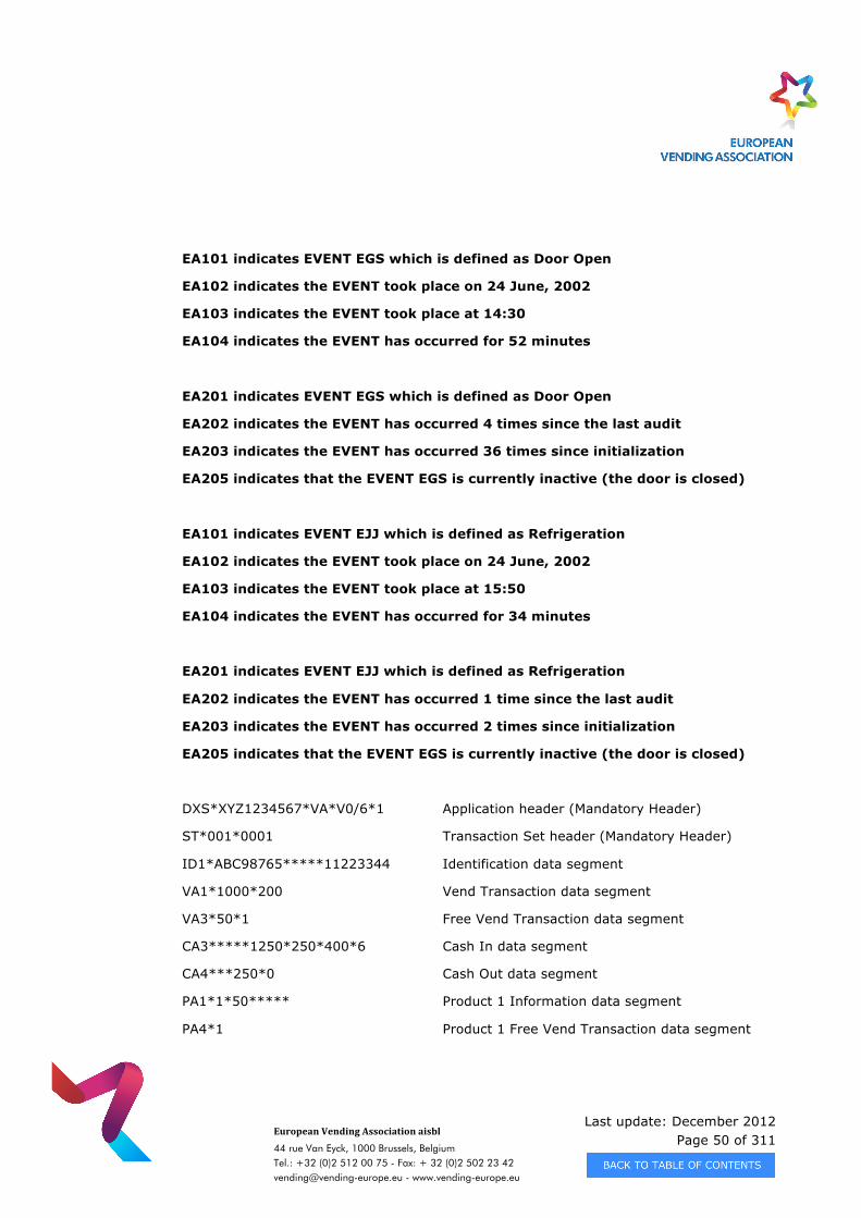
Last update: December 2012 Page 50 of 311
European Vending Association aisbl
44 rue Van Eyck, 1000 Brussels, Belgium Tel.: +32 (0)2 512 00 75 - Fax: + 32 (0)2 502 23 42 [email protected] - www.vending-europe.eu
EA101 indicates EVENT EGS which is defined as Door Open
EA102 indicates the EVENT took place on 24 June, 2002
EA103 indicates the EVENT took place at 14:30
EA104 indicates the EVENT has occurred for 52 minutes
EA201 indicates EVENT EGS which is defined as Door Open
EA202 indicates the EVENT has occurred 4 times since the last audit
EA203 indicates the EVENT has occurred 36 times since initialization
EA205 indicates that the EVENT EGS is currently inactive (the door is closed)
EA101 indicates EVENT EJJ which is defined as Refrigeration
EA102 indicates the EVENT took place on 24 June, 2002
EA103 indicates the EVENT took place at 15:50
EA104 indicates the EVENT has occurred for 34 minutes
EA201 indicates EVENT EJJ which is defined as Refrigeration
EA202 indicates the EVENT has occurred 1 time since the last audit
EA203 indicates the EVENT has occurred 2 times since initialization
EA205 indicates that the EVENT EGS is currently inactive (the door is closed)
DXS*XYZ1234567*VA*V0/6*1 Application header (Mandatory Header)
ST*001*0001 Transaction Set header (Mandatory Header)
ID1*ABC98765*****11223344 Identification data segment
VA1*1000*200 Vend Transaction data segment
VA3*50*1 Free Vend Transaction data segment
CA3*****1250*250*400*6 Cash In data segment
CA4***250*0 Cash Out data segment
PA1*1*50***** Product 1 Information data segment
PA4*1 Product 1 Free Vend Transaction data segment
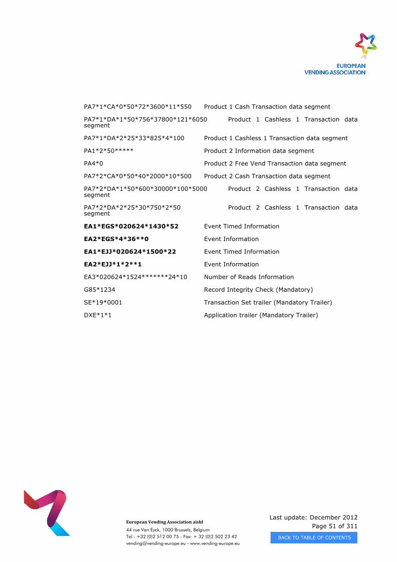
Last update: December 2012 Page 51 of 311
European Vending Association aisbl
44 rue Van Eyck, 1000 Brussels, Belgium Tel.: +32 (0)2 512 00 75 - Fax: + 32 (0)2 502 23 42 [email protected] - www.vending-europe.eu
PA7*1*CA*0*50*72*3600*11*550 Product 1 Cash Transaction data segment
PA7*1*DA*1*50*756*37800*121*6050 Product 1 Cashless 1 Transaction data segment
PA7*1*DA*2*25*33*825*4*100 Product 1 Cashless 1 Transaction data segment
PA1*2*50***** Product 2 Information data segment
PA4*0 Product 2 Free Vend Transaction data segment
PA7*2*CA*0*50*40*2000*10*500 Product 2 Cash Transaction data segment
PA7*2*DA*1*50*600*30000*100*5000 Product 2 Cashless 1 Transaction data segment
PA7*2*DA*2*25*30*750*2*50 Product 2 Cashless 1 Transaction data segment
EA1*EGS*020624*1430*52 Event Timed Information
EA2*EGS*4*36**0 Event Information
EA1*EJJ*020624*1500*22 Event Timed Information
EA2*EJJ*1*2**1 Event Information
EA3*020624*1524*******24*10 Number of Reads Information
G85*1234 Record Integrity Check (Mandatory)
SE*19*0001 Transaction Set trailer (Mandatory Trailer)
DXE*1*1 Application trailer (Mandatory Trailer)
Last update: December 2012 Page 52 of 311
European Vending Association aisbl
44 rue Van Eyck, 1000 Brussels, Belgium Tel.: +32 (0)2 512 00 75 - Fax: + 32 (0)2 502 23 42 [email protected] - www.vending-europe.eu
CHAPTER 3 - DATA TRANSFER USING ENHANCED DDCMP
A communications trace can be found in directory DDCMP Software available on the EVA website www.vending-europe.eu.
3.1 SCOPE
This chapter defines the Enhanced DDCMP, which is based on the previous (older) DDCMP Protocol
Implementation (EVA- DTS Version 4.1). Enhanced DDCMP specifies a method of transferring data either via an optical or a hardwire link within a vending environment.
The main features of EOP
Enhanced DDCMP are:
· Supports an optical bus for networking of more than one slave device. · Defines a hardware implementation compatible with IrDA. · Defines a protocol, based on the existing DDCMP implementation used in the
vending industry that can transmit data securely.
The following pages specify how to establish an IrDA - hardware compatible link, (also possible as a direct connect link), to allow networking of more than one slave device at transmission rates up to 115200 baud, using an optical link.
With these additions, Enhanced DDCMP allows data transfer between a handheld computer and a cashless payment system. As the transmission rate may be incremented up to 115200 bps, the amount of transferable data can be large enough for cashless payment systems as for future vending machines. One of the most important features of Enhanced DDCMP is that it is compatible with the older DDCMP protocols used by the vending industry.Enhanced DDCMP shall be used for all new developments of product complying with this specification. Chapter 6 contains some application notes to aid the practical implementation and support of the protocol as well as compatibility with the previous standard of DDCMP.
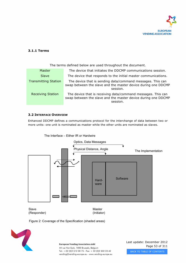
Last update: December 2012 Page 53 of 311
European Vending Association aisbl
44 rue Van Eyck, 1000 Brussels, Belgium Tel.: +32 (0)2 512 00 75 - Fax: + 32 (0)2 502 23 42 [email protected] - www.vending-europe.eu
3.1.1 Terms
The terms defined below are used throughout the document.
Master The device that initiates the DDCMP communications session.
Slave The device that responds to the initial master communications.
Transmitting Station The device that is sending data/command messages. This can swap between the slave and the master device during one DDCMP
session.
Receiving Station The device that is receiving data/command messages. This can swap between the slave and the master device during one DDCMP
session.
3.2 INTERFACE OVERVIEW
Enhanced DDCMP defines a communications protocol for the interchange of data between two or more units: one unit is nominated as master while the other units are nominated as slaves.
Slave(Responder)
Master(Initiator)
Optics, Data Messages
Physical Distance, Angle
The Interface – Either IR or Hardwire
The Implementation
Hard-ware
Software
Figure 2: Coverage of the Specification (shaded areas)
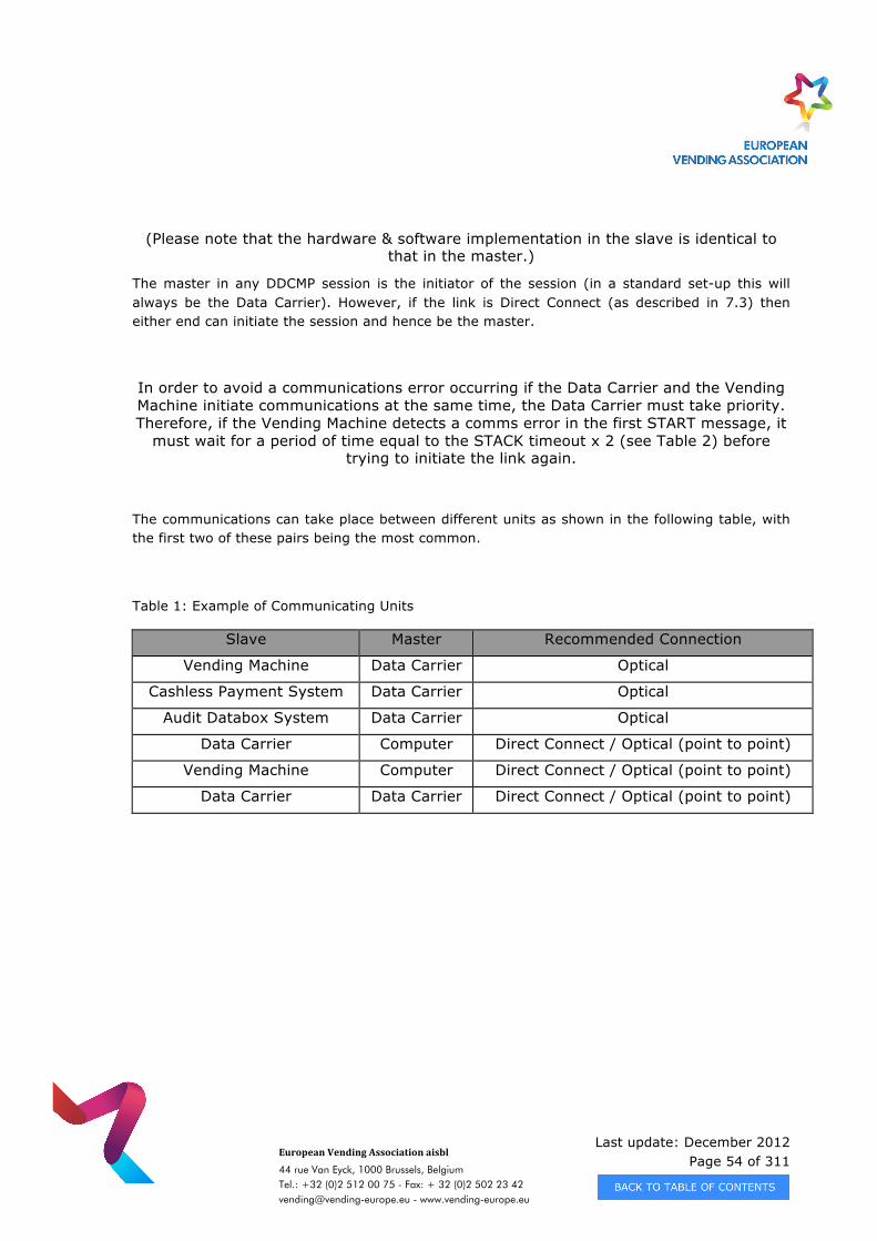
Last update: December 2012 Page 54 of 311
European Vending Association aisbl
44 rue Van Eyck, 1000 Brussels, Belgium Tel.: +32 (0)2 512 00 75 - Fax: + 32 (0)2 502 23 42 [email protected] - www.vending-europe.eu
(Please note that the hardware & software implementation in the slave is identical to that in the master.)
The master in any DDCMP session is the initiator of the session (in a standard set-up this will always be the Data Carrier). However, if the link is Direct Connect (as described in 7.3) then either end can initiate the session and hence be the master.
In order to avoid a communications error occurring if the Data Carrier and the Vending Machine initiate communications at the same time, the Data Carrier must take priority. Therefore, if the Vending Machine detects a comms error in the first START message, it
must wait for a period of time equal to the STACK timeout x 2 (see Table 2) before trying to initiate the link again.
The communications can take place between different units as shown in the following table, with the first two of these pairs being the most common.
Table 1: Example of Communicating Units
Slave Master Recommended Connection
Vending Machine Data Carrier Optical
Cashless Payment System Data Carrier Optical
Audit Databox System Data Carrier Optical
Data Carrier Computer Direct Connect / Optical (point to point)
Vending Machine Computer Direct Connect / Optical (point to point)
Data Carrier Data Carrier Direct Connect / Optical (point to point)
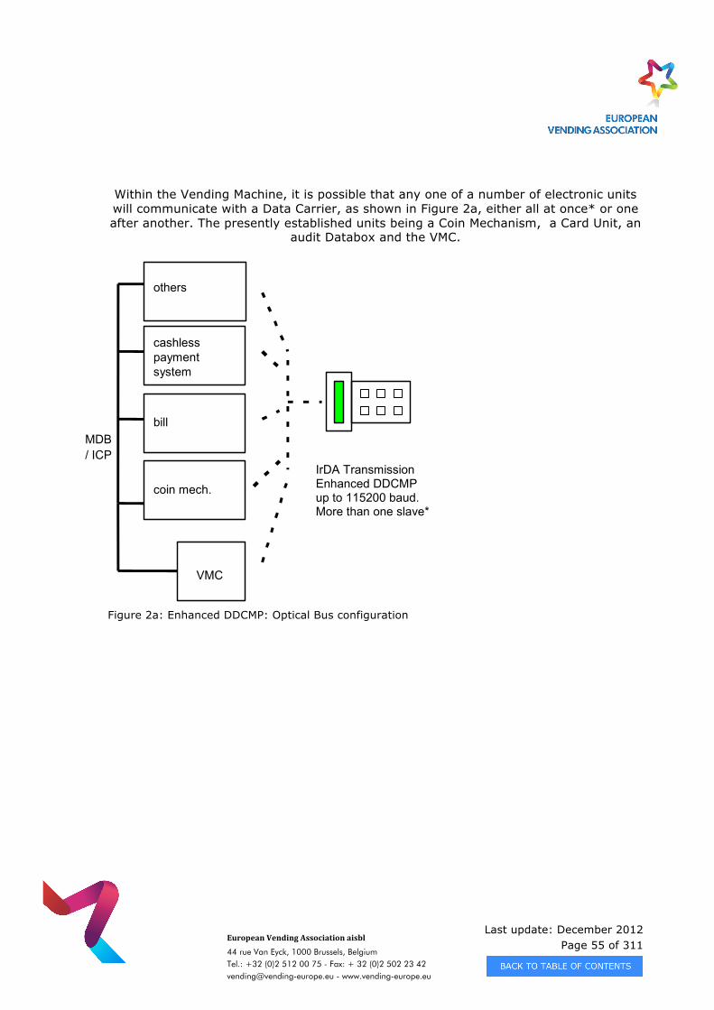
Last update: December 2012 Page 55 of 311
European Vending Association aisbl
44 rue Van Eyck, 1000 Brussels, Belgium Tel.: +32 (0)2 512 00 75 - Fax: + 32 (0)2 502 23 42 [email protected] - www.vending-europe.eu
Within the Vending Machine, it is possible that any one of a number of electronic units will communicate with a Data Carrier, as shown in Figure 2a, either all at once* or one after another. The presently established units being a Coin Mechanism, a Card Unit, an
audit Databox and the VMC.
Figure 2a: Enhanced DDCMP: Optical Bus configuration
VMC
coin mech.IrDA TransmissionEnhanced DDCMPup to 115200 baud.More than one slave*
billvalidator
cashlesspaymentsystem
others
MDB/ ICP
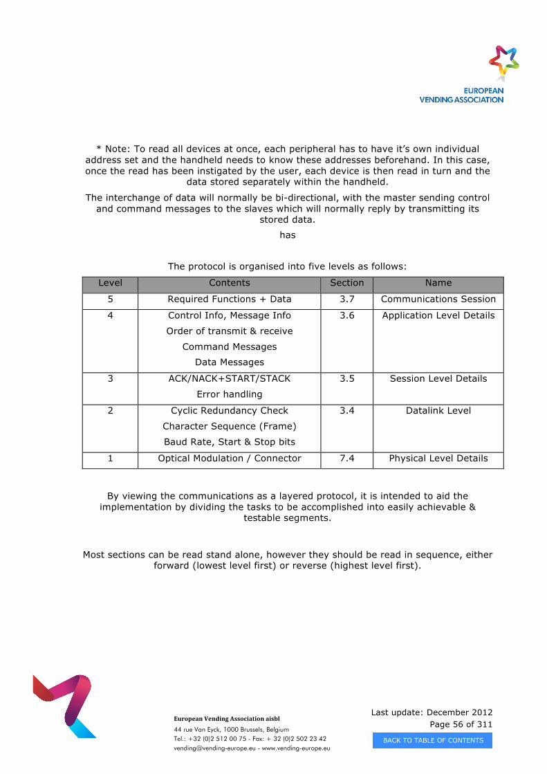
Last update: December 2012 Page 56 of 311
European Vending Association aisbl
44 rue Van Eyck, 1000 Brussels, Belgium Tel.: +32 (0)2 512 00 75 - Fax: + 32 (0)2 502 23 42 [email protected] - www.vending-europe.eu
* Note: To read all devices at once, each peripheral has to have it’s own individual address set and the handheld needs to know these addresses beforehand. In this case, once the read has been instigated by the user, each device is then read in turn and the
data stored separately within the handheld.
The interchange of data will normally be bi-directional, with the master sending control and command messages to the slaves which will normally reply by transmitting its
stored data.
has
The protocol is organised into five levels as follows:
Level Contents Section Name
5 Required Functions + Data 3.7 Communications Session
4 Control Info, Message Info
Order of transmit & receive
Command Messages
Data Messages
3.6 Application Level Details
3 ACK/NACK+START/STACK
Error handling
3.5 Session Level Details
2 Cyclic Redundancy Check
Character Sequence (Frame)
Baud Rate, Start & Stop bits
3.4 Datalink Level
1 Optical Modulation / Connector 7.4 Physical Level Details
By viewing the communications as a layered protocol, it is intended to aid the implementation by dividing the tasks to be accomplished into easily achievable &
testable segments.
Most sections can be read stand alone, however they should be read in sequence, either forward (lowest level first) or reverse (highest level first).
Last update: December 2012 Page 57 of 311
European Vending Association aisbl
44 rue Van Eyck, 1000 Brussels, Belgium Tel.: +32 (0)2 512 00 75 - Fax: + 32 (0)2 502 23 42 [email protected] - www.vending-europe.eu
3.2.1 General Data Transfer Operation
Before communications can be started, the devices must be 'connected' either optically, by placing the master's optical Tx/Rx unit within 1 metre of the slaves’, or directly,
using the jack plug and socket.
Once the slave device is idle (i.e. not executing any function) it will automatically respond to communications activity from the master device. The master device initiates a communications session by sending a ‘start’ command. Thereafter, until the master device sends a 'finish' command to terminate the communication session, the slave device will obey any command it receives provided the slave’s address matches the
masters requesting address.
If any abnormalities are detected in the communications such that it is not possible to carry on with the sequence of commands, the master device can re-initialise the
communications link. The slave device will abort whatever it was doing and revert to waiting for a command. (See application note 6.2.2.5)
As a safeguard against communications link malfunction, the slave devices will automatically terminate communications if there has been no communications activity
for a specified timeout. (Receive data message/link time-out, see table 2).
If the master device wishes to keep the communications link active then it should send commands within the Receive data message/link time-out of each other. One of the
commands – ‘WhoAreYou’ - can be used to keep the link alive, assuming there are no other actions the master device wishes to perform.
The automatic communications start-up means that slaves can be left unattended at a remote site (e.g. if connected via a modem and the telephone system). If long delays occur, e.g. if re-dialling after losing a telephone connection, the Master can simply re-
start communications without any manual intervention.
Last update: December 2012 Page 58 of 311
European Vending Association aisbl
44 rue Van Eyck, 1000 Brussels, Belgium Tel.: +32 (0)2 512 00 75 - Fax: + 32 (0)2 502 23 42 [email protected] - www.vending-europe.eu
3.3 PHYSICAL LEVEL DETAILS
Please refer to chapter 7 for details of the IrDA and direct connect physical layers.
The optical Link is IrDA-1.0 compatible at the physical layer only. For more detailed information refer to the IrDA Physical Signaling Layer Specification, which can be found
on the IrDA web site, Uwww.irda.orgU.
3.4 DATALINK LEVEL
The Datalink Message Level provides a means of communicating a data message, without error, between at least two stations on a communications link.
The protocol used is loosely based on a sub-set of the DEC Data Communications Message Protocol (DDCMP) designed by Digital Equipment Corporation. It is also an extension to the EVA-DTS DDCMP implementation as described in version 4.1. The
reader may wish to refer to the DDCMP Specification document number AA-DS99A-TC for details of the original protocol.
It is the intention of this specification to contain sufficient information to allow an implementer to proceed without reference to the formal DDCMP specification. The
DDCMP functions implemented are :
Initialise link.
Transmit data message.
Receive data message.
The Datalink level is the lower 'layer' of the Enhanced DDCMP implementation. As such
it deals principally with four items :
· Initialisation & message counting (START,STACK + ACK,NACK). · Cyclic Redundancy Check. · Character Sequencing (framing). · Error Handling.
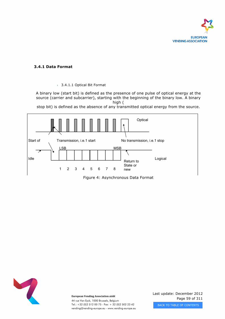
Last update: December 2012 Page 59 of 311
European Vending Association aisbl
44 rue Van Eyck, 1000 Brussels, Belgium Tel.: +32 (0)2 512 00 75 - Fax: + 32 (0)2 502 23 42 [email protected] - www.vending-europe.eu
3.4.1 Data Format
› 3.4.1.1 Optical Bit Format
A binary low (start bit) is defined as the presence of one pulse of optical energy at the source (carrier and subcarrier), starting with the beginning of the binary low. A binary
high (stop bit) is defined as the absence of any transmitted optical energy from the source.
Figure 4: Asynchronous Data Format
IdleState
LSB MSB
1 2 3 4 5 6 7 8
Return toIdleState orStartnewcharacter
Start ofOptics
Transmission, i.e.1 startbit
No transmission, i.e.1 stopbit
OpticalSignal
LogicalSignal
Last update: December 2012 Page 60 of 311
European Vending Association aisbl
44 rue Van Eyck, 1000 Brussels, Belgium Tel.: +32 (0)2 512 00 75 - Fax: + 32 (0)2 502 23 42 [email protected] - www.vending-europe.eu
› 3.4.1.2 Byte Format
10 bits / byte, consisting of one start bit, 8 data bits, and one stop bit. The data bits are transmitted least significant bit first (after start bit) and most significant bit last (before
stop bit). There are no general restrictions as to data values.
3.4.2 Basic Transmission Parameters
The communications link can handle, in half duplex mode, transmission and reception of any 8 bit character combination.
› 3.4.2.1Transmission Rate
Standard starting Rate: 2400 Baud
Maximum high speed Rate:115200 Baud
The actual baud rate used will be the lowest common baud rate supported by the 2 link nodes.
› 3.4.2.1 Synchronisation
3.4.2.2.1 Bit Sync
Intrinsic to link receiver circuits, with a maximum timing skew of up to 25% of the bit width in any bit of a transmitted character no error on reception should be caused.
Last update: December 2012 Page 61 of 311
European Vending Association aisbl
44 rue Van Eyck, 1000 Brussels, Belgium Tel.: +32 (0)2 512 00 75 - Fax: + 32 (0)2 502 23 42 [email protected] - www.vending-europe.eu
3.4.2.2.2 Byte Sync
Asynchronous with start bit & stop bit framing. 3.4.2.2.3 Transmission Sync
During start and start acknowledge sequence, some bytes of the START and STACK messages are used to define the master’s baud rate and the slave’s baud rate
capability. If a new baud rate is necessary, an additional START and STACK message sequence is required at the new baud rate to establish the new rate.
See control messages (section 3.6.2) for details.
NOTE 1: An example of changing speed characteristics is detailed in the application notes section (6.2.1.1).
NOTE 2: If older peripherals are to be supported for compatibility reasons, refer to EVA-DTS 4.1 for start-up sequence.
3.4.2.2.4 Message Sync
Message framing shall be dependent on detection of specific bytes within the message to define the start and length of each message in the case of variable length messages.
Alternatively, in the case of fixed length messages, the message framing shall be in accordance with this specification and may be determined during a sequence of
messages by reference to the message type or number within the sequence.
Message framing is done in two different ways:
• Fixed length messages have a specific format, as detailed below in the specification.
• Variable length messages: Length data is always passed in bytes 2 and 3 of the data message header.
Last update: December 2012 Page 62 of 311
European Vending Association aisbl
44 rue Van Eyck, 1000 Brussels, Belgium Tel.: +32 (0)2 512 00 75 - Fax: + 32 (0)2 502 23 42 [email protected] - www.vending-europe.eu
3.4.3 Message Framing
The Enhanced DDCMP's fundamental unit of transmission is a collection of characters, or 'frames'. In the majority of frames the first character implies exactly how many
characters are expected to be received in the frame being transmitted. In the case of some data messages the first character implies a variable length frame and a
subsequent character (usually the second or third) either implies or defines, dependent on the message, exactly how long this frame being transmitted actually is.
As would be expected, there are lower level communications modules which deal with transmitting each character within the frame, and each bit within the character. These
are not usually regarded as forming part of the Enhanced DDCMP modules.
The purpose of framing is to provide a robust communications channel which is resistant to errors and capable of ‘clean' recovery when errors do occur.
3.4.4 Data Length Restrictions
The implementation of the Enhanced DDCMP link assumes a multiple point-to-point half duplex communications link i.e. transmission in one direction at a time. In this
implementation one message is sent at a time, awaiting an acknowledgement before a further message is sent: i.e. no pipe-lining is handled. Data messages are restricted in
length as follows:
from master to slave:
Blocks up to 16383 bytes, subject to slave buffer size, comprised of: • 8 bytes for an ACK to a pre-sent transmitted message. • 8 bytes for message header. • 2 bytes for message data block ID and message number. • up to 16365 bytes as data. • 2 bytes for data CRC. • to a maximum data file length of 64k bytes (the Enhanced DDCMP limit)
& then a new data message is needed, or • to an unlimited data file length, using the select flag mechanism to
transmit data messages of unknown length.
Last update: December 2012 Page 63 of 311
European Vending Association aisbl
44 rue Van Eyck, 1000 Brussels, Belgium Tel.: +32 (0)2 512 00 75 - Fax: + 32 (0)2 502 23 42 [email protected] - www.vending-europe.eu
from slave to master:
Blocks up to 16383 bytes, subject to transmit buffer size which is implementation specific, comprised of: • 8 bytes for an ACK to a pre-sent transmitted message. • 8 bytes for message header. • 2 bytes for message data block ID and message number. • up to 16365 bytes as data. • 2 bytes for data CRC. • to a maximum data file length of 64k bytes (the Enhanced DDCMP limit),
or • to an unlimited data file length, using the select flag mechanism to
transmit data messages of unknown length. The recommended default buffer length is 256 bytes throughout the system. Alternate
slave buffer lengths are to be explicitly communicated using the ‘Who Are You’ command/response sequence.
3.4.5 Cyclic Redundancy Check
All messages have a fixed length header (6 bytes) followed by two CRC-16 check bytes. Message framing by the receiving end is achieved when the header, starting with one of
three possible byte values, is received with a valid CRC-16 check.
The type of message is indicated by the first, and sometimes the second byte, in the header. All Control Messages consist of just the header. Data Messages consist of the header which specifies the length (in bytes) of all of the data, followed by the current data block. Two CRC-16 check bytes follow the data block. These apply to the data
bytes only.
The CRC-16 algorithm used is:
p(x) = x^16 + x^15 + x^2 + x^0
Examples of how to code this in C and Assembler are shown in Section 6.1.2.
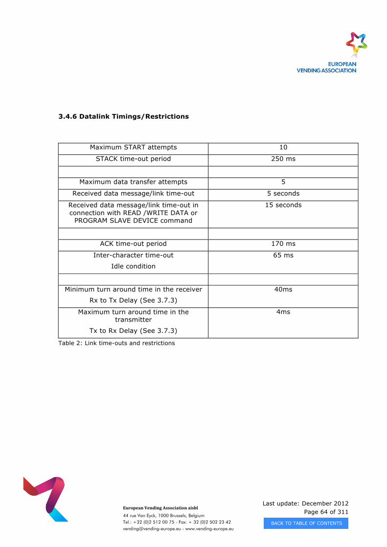
Last update: December 2012 Page 64 of 311
European Vending Association aisbl
44 rue Van Eyck, 1000 Brussels, Belgium Tel.: +32 (0)2 512 00 75 - Fax: + 32 (0)2 502 23 42 [email protected] - www.vending-europe.eu
3.4.6 Datalink Timings/Restrictions
Maximum START attempts 10
STACK time-out period 250 ms
Maximum data transfer attempts 5
Received data message/link time-out 5 seconds
Received data message/link time-out in connection with READ /WRITE DATA or
PROGRAM SLAVE DEVICE command
15 seconds
ACK time-out period 170 ms
Inter-character time-out
Idle condition
65 ms
Minimum turn around time in the receiver
Rx to Tx Delay (See 3.7.3)
40ms
Maximum turn around time in the transmitter
Tx to Rx Delay (See 3.7.3)
4ms
Table 2: Link time-outs and restrictions
Last update: December 2012 Page 65 of 311
European Vending Association aisbl
44 rue Van Eyck, 1000 Brussels, Belgium Tel.: +32 (0)2 512 00 75 - Fax: + 32 (0)2 502 23 42 [email protected] - www.vending-europe.eu
3.5 SESSION LEVEL
› 3.5.1.1 Initialisation & Maintenance
There are two parts to low level synchronisation, firstly initialising the link and secondly keeping the link going.
Low level initialisation is achieved by the master transmitting a START control message at a standard rate of 2400 baud.
The slave station should respond with a STACK (STart ACKnowledge) control message, whenever its slave address matches the requested address.
A second START/STACK pair will be exchanged, at a new baud rate, if baud rates are changed (i.e. slave agrees to speed suggested by master).
Data may then be passed between the stations by enclosing it in a data message for transfer across the communications link. Each data message transmitted by a station
will require an ACK control message to be transmitted by the other station when it has successfully received the data message. Non-arrival of the ACK within the specified time period ( ACK time out period, table 2 ) will indicate to the transmitting station that the transmission was not successful or there was no slave with such an address and will be
treated similar to a NACK. (See application note 6.2.2.3).
Enhanced DDCMP incorporates a NACK control message to allow a speedier indication of certain error conditions such as corrupt data. If error conditions occur, the transmitting
station will re-attempt the transfer a number of times before finally giving up ( Maximum data transfer attempts, table 2). (See application note 6.2.2.4).
Last update: December 2012 Page 66 of 311
European Vending Association aisbl
44 rue Van Eyck, 1000 Brussels, Belgium Tel.: +32 (0)2 512 00 75 - Fax: + 32 (0)2 502 23 42 [email protected] - www.vending-europe.eu
› 3.5.1.2 Data Message Sequence Number Checking
Each station must maintain two message sequence numbers:
• Transmit Number - the number of the current message being transmitted.
• Receive Number - the number of the current message being received.
Successful transmission of a message occurs when the number in the message (the Transmit Number in the transmitting station) is the same as the Receive Number in the
receiving station.
The use of data message sequence numbers allows the possibility for a data message to be used as an ACK to a data message sent in the previous direction. This is referred to as the 'piggy-back ACK' mechanism and allows a reduction in the protocol overhead on
a busy half-duplex communications link.
This feature of the sequence number mechanism handles the case where an ACK control message is not successfully received. In such a case the transmitting station will
re-transmit the original message. The receiving station will see a sequence error so send a NACK. The effect is that the original transmitting station will see a matching
sequence number in the response and so assume that the message transfer was successful. (See application note 6.2.2.6).
Note that if the data message transfer has failed (Max data transfer attempts reached) and the receiving station does not respond to any attempts to reinitialise the link, then
the transmitting station should give up and indicate that an error has occurred.
Note 1: The message sequence number mechanism described here is a much-simplified form of that available in a full DDCMP implementation. This is because, unlike the full implementation in which a single ACK will serve to acknowledge a sequence of data messages, each data message will be acknowledged individually.
Note 2: Message numbering should always start with 1.
Last update: December 2012 Page 67 of 311
European Vending Association aisbl
44 rue Van Eyck, 1000 Brussels, Belgium Tel.: +32 (0)2 512 00 75 - Fax: + 32 (0)2 502 23 42 [email protected] - www.vending-europe.eu
3.5.2 Error Handling
The Datalink level exists to overcome errors on a communications link. If the link was not subject to errors then there would be no need for the protocol level. Error handling
is, therefore, an inherent part of the protocol and has been included in the rules for data transfer described further below. The current section serves to amplify some
points concerning the detection of and recovery from errors.
› 3.5.2.1 Error And Abnormal Conditions
All messages incorporate redundancy checks i.e. CRC’s to allow detection of corrupted data. Data messages are assigned sequence numbers to allow detection of lost or
repeated messages.
An error or abnormal condition exists when one of the following occurs:
• A message does not arrive within a specified time • A message contains an unexpected slave address • A message is corrupted (its contents do not match the redundancy check
value) • Data message sequence numbers do not match • Data message is too long for the receiving station to handle. • A START message is received during a message transfer sequence. • An unexpected type of message arrives, e.g. an ACK instead of a data
message. • The station address is invalid.
It is also possible for incomplete messages to be received. In this case, the assumption is that receive overrun has occurred causing loss of characters. This is regarded as a
corrupt data condition rather than a receive time-out.
Last update: December 2012 Page 68 of 311
European Vending Association aisbl
44 rue Van Eyck, 1000 Brussels, Belgium Tel.: +32 (0)2 512 00 75 - Fax: + 32 (0)2 502 23 42 [email protected] - www.vending-europe.eu
› 3.5.2.2 Recovery
When an error or abnormal condition occurs it is important for the receiving station to maintain synchronisation or re-establish synchronisation with the transmitting station.
If the message is not corrupt then, ideally, the receiving station should be able to continue to the end of the message (if not already there). If the message is corrupt:
• The receiving station scans the character stream looking for the sequence that identifies a new message – at the current baud rate.
• The transmitting station waits for idle (no communication activity), before attempting to send next message – at the current baud rate.
The main classes of recovery action are:
1. Immediate termination of the transfer attempt if:
• Receiving station does not receive message within specified time period (Received data message/link time-out, table 2).
• START message received (at the current baud rate).
2. Receiving station sends a NACK control message and waits for retransmission of the data message if:
• corrupt data. • data message sequence number mismatch. • data too long for buffer. • buffer temporarily unavailable.
3. Transmitting station re-transmits the data message if:
• no acknowledgement (within ACK timeout, table 2). • corrupt acknowledgement. • ACK with out-of-sequence message numbers. • NACK received with out-of-sequence message numbers.
4. Receiving station waits for re-transmission of the data message if:
• any other error or abnormal condition occurs
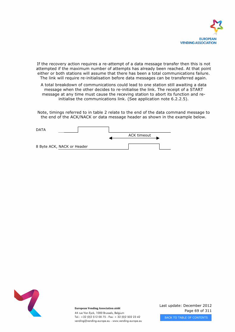
Last update: December 2012 Page 69 of 311
European Vending Association aisbl
44 rue Van Eyck, 1000 Brussels, Belgium Tel.: +32 (0)2 512 00 75 - Fax: + 32 (0)2 502 23 42 [email protected] - www.vending-europe.eu
If the recovery action requires a re-attempt of a data message transfer then this is not attempted if the maximum number of attempts has already been reached. At that point either or both stations will assume that there has been a total communications failure.
The link will require re-initialisation before data messages can be transferred again.
A total breakdown of communications could lead to one station still awaiting a data message when the other decides to re-initialise the link. The receipt of a START
message at any time must cause the receving station to abort its function and re-initialise the communications link. (See application note 6.2.2.5).
Note, timings referred to in table 2 relate to the end of the data command message to the end of the ACK/NACK or data message header as shown in the example below.
DATA
8 Byte ACK, NACK or Header
ACK timeout
Last update: December 2012 Page 70 of 311
European Vending Association aisbl
44 rue Van Eyck, 1000 Brussels, Belgium Tel.: +32 (0)2 512 00 75 - Fax: + 32 (0)2 502 23 42 [email protected] - www.vending-europe.eu
3.6 APPLICATION LEVEL DETAILS
3.6.1 Message Types
Control and Data Messages may be distinguished by the first character (Hex representation) in the message string:
'05' - Indicates a Control Message
'81' - Indicates a Data Message
Within Data Messages, there is another level of differentiation, as indicated by the first character of the Data Block following the Data Message Header:
'77' - Indicates a Command Message
'88' - Indicates a Command Message Response
'99' - Indicates a Data Block
Last update: December 2012 Page 71 of 311
European Vending Association aisbl
44 rue Van Eyck, 1000 Brussels, Belgium Tel.: +32 (0)2 512 00 75 - Fax: + 32 (0)2 502 23 42 [email protected] - www.vending-europe.eu
The various message types are listed below :
Control Messages
Start ("START")
Start Acknowledge ("STACK")
Acknowledge ("ACK")
No Acknowledge ("NACK")
Data Messages
Command Messages* Hex Designators
Who Are You 77 + E0
Program Slave Device 77 + E1
Read Data** 77 + E2
Write Data** 77 + E3
Delete Data 77 + E4
Program Module 77 + E5
Read Memory 77 + E6
Finish Communications 77 + FF
Command Responses*
Who Are You – Accepted / Rejected 88 + E0
Program Slave Device - Accepted / Rejected 88 + E1
Read Data – Accepted / Rejected 88 + E2
Write Data – Accepted / Rejected 88 + E3
Delete Data – Accepted / Rejected 88 + E4
Program Module – Accepted / Rejected 88 + E5
Read Memory – Accepted / Rejected 88 + E6
Application Data Messages*
Data Blocks 99 +
Last update: December 2012 Page 72 of 311
European Vending Association aisbl
44 rue Van Eyck, 1000 Brussels, Belgium Tel.: +32 (0)2 512 00 75 - Fax: + 32 (0)2 502 23 42 [email protected] - www.vending-europe.eu
* - These items are treated as an enhanced DDCMP data message, i.e. contains a CRC suffix and is preceded by a Data Message Header with its own CRC suffix.
** - used to read and write EVA-DTS reports.
› 3.6.1.1 Message Format
Control Message 8 Bytes header only (including 2 byte CRC)
Data Message 8 Bytes header (including 2 byte CRC) + Variable length data field.
The Data Message Protocol sends Control, Command and Data Block messages in two fundamental forms. The first of these applies solely to Control Messages, all of which are sent exactly as shown in a subsequent section in this chapter. The second form applies to all other forms of message, which in strict Enhanced DDCMP terms are
treated as Data Messages, and are all prefixed by the same Data Message Header.
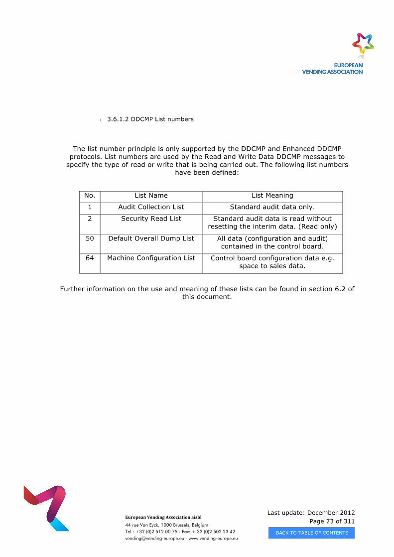
Last update: December 2012 Page 73 of 311
European Vending Association aisbl
44 rue Van Eyck, 1000 Brussels, Belgium Tel.: +32 (0)2 512 00 75 - Fax: + 32 (0)2 502 23 42 [email protected] - www.vending-europe.eu
› 3.6.1.2 DDCMP List numbers
The list number principle is only supported by the DDCMP and Enhanced DDCMP protocols. List numbers are used by the Read and Write Data DDCMP messages to
specify the type of read or write that is being carried out. The following list numbers have been defined:
No. List Name List Meaning
1 Audit Collection List Standard audit data only.
2 Security Read List Standard audit data is read without resetting the interim data. (Read only)
50 Default Overall Dump List All data (configuration and audit) contained in the control board.
64 Machine Configuration List Control board configuration data e.g. space to sales data.
Further information on the use and meaning of these lists can be found in section 6.2 of this document.
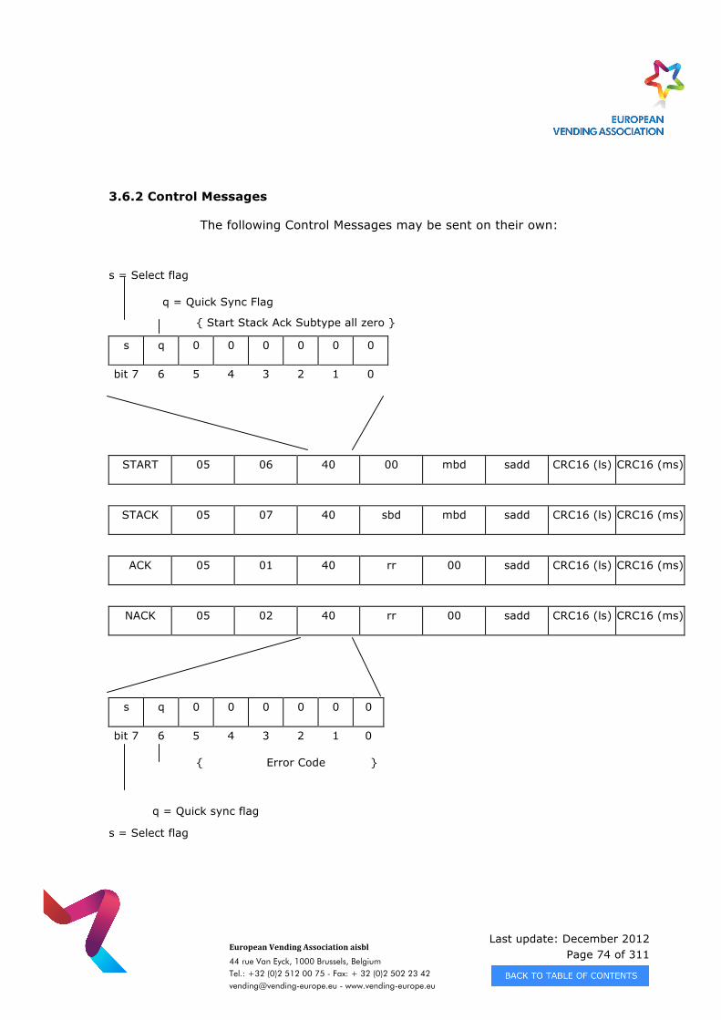
Last update: December 2012 Page 74 of 311
European Vending Association aisbl
44 rue Van Eyck, 1000 Brussels, Belgium Tel.: +32 (0)2 512 00 75 - Fax: + 32 (0)2 502 23 42 [email protected] - www.vending-europe.eu
3.6.2 Control Messages
The following Control Messages may be sent on their own:
s = Select flag
q = Quick Sync Flag
{ Start Stack Ack Subtype all zero }
s q 0 0 0 0 0 0
bit 7 6 5 4 3 2 1 0
START 05 06 40 00 mbd sadd CRC16 (ls) CRC16 (ms)
STACK 05 07 40 sbd mbd sadd CRC16 (ls) CRC16 (ms)
ACK 05 01 40 rr 00 sadd CRC16 (ls) CRC16 (ms)
NACK 05 02 40 rr 00 sadd CRC16 (ls) CRC16 (ms)
s q 0 0 0 0 0 0
bit 7 6 5 4 3 2 1 0
{ Error Code }
q = Quick sync flag
s = Select flag
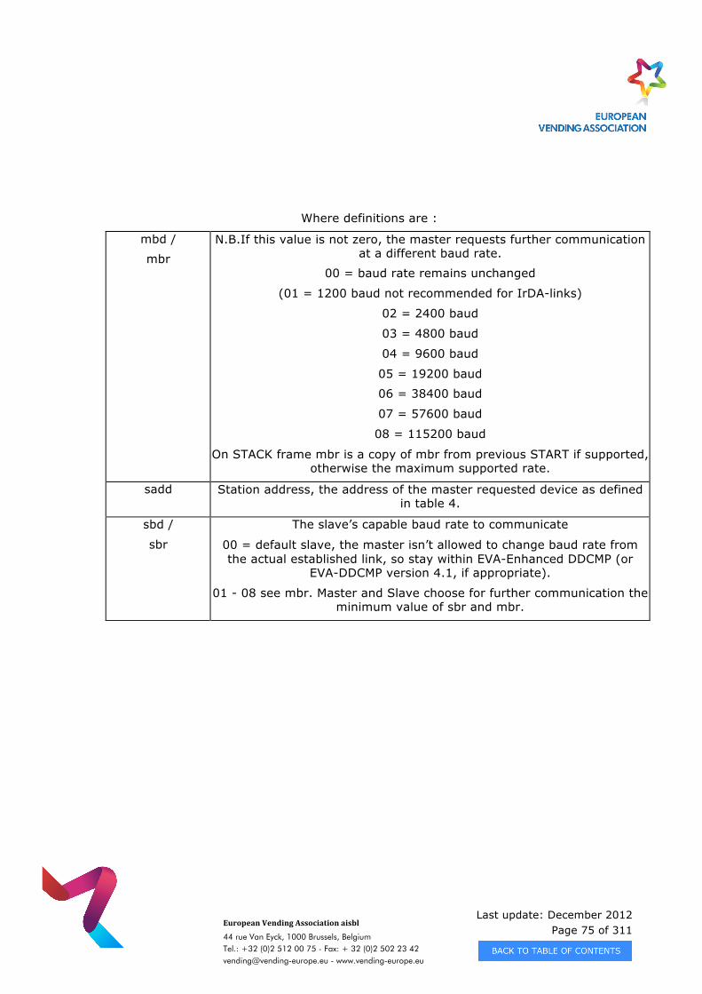
Last update: December 2012 Page 75 of 311
European Vending Association aisbl
44 rue Van Eyck, 1000 Brussels, Belgium Tel.: +32 (0)2 512 00 75 - Fax: + 32 (0)2 502 23 42 [email protected] - www.vending-europe.eu
Where definitions are :
mbd /
mbr N.B.If this value is not zero, the master requests further communication
at a different baud rate.
00 = baud rate remains unchanged
(01 = 1200 baud not recommended for IrDA-links)
02 = 2400 baud
03 = 4800 baud
04 = 9600 baud
05 = 19200 baud
06 = 38400 baud
07 = 57600 baud
08 = 115200 baud
On STACK frame mbr is a copy of mbr from previous START if supported, otherwise the maximum supported rate.
sadd Station address, the address of the master requested device as defined in table 4.
sbd /
sbr
The slave’s capable baud rate to communicate
00 = default slave, the master isn’t allowed to change baud rate from the actual established link, so stay within EVA-Enhanced DDCMP (or
EVA-DDCMP version 4.1, if appropriate).
01 - 08 see mbr. Master and Slave choose for further communication the minimum value of sbr and mbr.
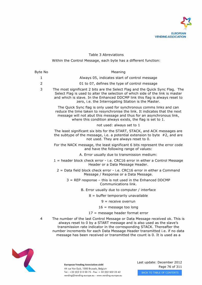
Last update: December 2012 Page 76 of 311
European Vending Association aisbl
44 rue Van Eyck, 1000 Brussels, Belgium Tel.: +32 (0)2 512 00 75 - Fax: + 32 (0)2 502 23 42 [email protected] - www.vending-europe.eu
Table 3 Abreviations
Within the Control Message, each byte has a different function:
Byte No Meaning
1 Always 05, indicates start of control message
2 01 to 07, defines the type of control message
3 The most significant 2 bits are the Select Flag and the Quick Sync Flag. The Select Flag is used to alter the selection of which side of the link is master and which is slave. In the Enhanced DDCMP link this flag is always reset to
zero, i.e. the Interrogating Station is the Master.
The Quick Sync flag is only used for synchronous comms links and can reduce the time taken to resynchronise the link. It indicates that the next message will not abut this message and thus for an asynchronous link,
where this condition always exists, the flag is set to 1.
not used: always set to 1
The least significant six bits for the START, STACK, and ACK messages are the subtype of the message, i.e. a potential extension to byte #2, and are
not used. They are always reset to 0.
For the NACK message, the least significant 6 bits represent the error code and have the following range of values:
A. Error usually due to transmission medium:
1 = header block check error - i.e. CRC16 error in either a Control Message Header or a Data Message Header.
2 = Data field block check error - i.e. CRC16 error in either a Command Message / Response or a Data Message.
3 = REP response – this is not used in the Enhanced DDCMP Communications link.
B. Error usually due to computer / interface
8 = buffer temporarily unavailable
9 = receive overrun
16 = message too long
17 = message header format error
4 The number of the last Control Message or Data Message received ok. This is always reset to 0 by a START message and is also used as the slave’s transmission rate indicator in the corresponding STACK. Thereafter the
number increments for each Data Message Header transmitted i.e. if no data message has been received or transmitted the count is 0. It is used as a
Last update: December 2012 Page 77 of 311
European Vending Association aisbl
44 rue Van Eyck, 1000 Brussels, Belgium Tel.: +32 (0)2 512 00 75 - Fax: + 32 (0)2 502 23 42 [email protected] - www.vending-europe.eu
check on message synchronisation by the Master. (see application note 6.2.1.1)
5 This is a 'fill byte' and is always reset to 0, whereas during start/stack, it is used to identify the masters requesting transmission rate
6 The Station Address field or Network Node, always set to 1 in point to point old DDCMP communications (broadcast request). All values except 1 indicate
the slave must check the requested address matches it’s own before it responds.
7,8 CRC 16 Code for block check error detection.
› 3.6.2.1 Predefined Address Values
Using standard DDCMP:
In the older links, the value of sadd is always 0x01. In EVA V4.1, each transaction contains sadd = 0x01 and establishes a point to point connection, so each device
answers to a 0x01 request. Therefore, for compatibility with that revision, each slave has to answer to 0x01 address.
Using Enhanced DDCMP:
If sadd is different from 0x01, it signals an addressed connection and only the slave with the matching address will answer.
N.B. A higher baud rate can still be negotiated with the slave device, even if it has a default address of 0x01, as long as it indicates it can support higher baud rates i.e. sbd
> 0.
Table 4 defines a set of addresses either reserved or defined by this standard. The address of a device should default to the value shown, but the device must be capable
of being manually altered to avoid any device clashes.
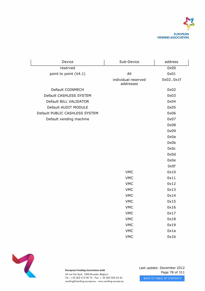
Last update: December 2012 Page 78 of 311
European Vending Association aisbl
44 rue Van Eyck, 1000 Brussels, Belgium Tel.: +32 (0)2 512 00 75 - Fax: + 32 (0)2 502 23 42 [email protected] - www.vending-europe.eu
Device Sub-Device address
reserved 0x00
point to point (V4.1) All 0x01
individual reserved addresses
0x02..0x1f
Default COINMECH 0x02
Default CASHLESS SYSTEM 0x03
Default BILL VALIDATOR 0x04
Default AUDIT MODULE 0x05
Default PUBLIC CASHLESS SYSTEM 0x06
Default vending machine 0x07
0x08
0x09
0x0a
0x0b
0x0c
0x0d
0x0e
0x0f
VMC 0x10
VMC 0x11
VMC 0x12
VMC 0x13
VMC 0x14
VMC 0x15
VMC 0x16
VMC 0x17
VMC 0x18
VMC 0x19
VMC 0x1a
VMC 0x1b
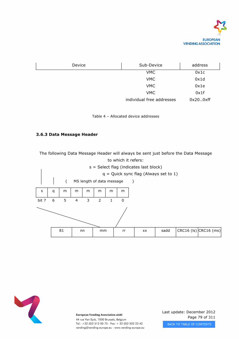
Last update: December 2012 Page 79 of 311
European Vending Association aisbl
44 rue Van Eyck, 1000 Brussels, Belgium Tel.: +32 (0)2 512 00 75 - Fax: + 32 (0)2 502 23 42 [email protected] - www.vending-europe.eu
Device Sub-Device address
VMC 0x1c
VMC 0x1d
VMC 0x1e
VMC 0x1f
individual free addresses 0x20..0xff
Table 4 – Allocated device addresses
3.6.3 Data Message Header
The following Data Message Header will always be sent just before the Data Message
to which it refers:
s = Select flag (indicates last block)
q = Quick sync flag (Always set to 1)
{ MS length of data message }
s q m m m m m m
bit 7 6 5 4 3 2 1 0
81 nn mm rr xx sadd CRC16 (ls) CRC16 (ms)
Last update: December 2012 Page 80 of 311
European Vending Association aisbl
44 rue Van Eyck, 1000 Brussels, Belgium Tel.: +32 (0)2 512 00 75 - Fax: + 32 (0)2 502 23 42 [email protected] - www.vending-europe.eu
mm = MS Length of Data Message
nn = LS Length of Data Message
rr = No. of last Rx OK (not data block)
xx = No. of this Tx (not data block)
Within the Data Message Header, each byte has a different function:
Byte No Meaning
1 Always 81, indicates start of data message header
2 LS length of the data message immediately following the header.
3 The most significant 2 bits are the Select Flag and the Quick Sync Flag. Select Flag is used to handle data transfers of data files of unknown length, set to 1 if
last block being transmitted. Quick sync flag is always set to 1. The least significant six bits of the data message header are the ms length of the data message immediately following the header. Thus there are 14 bits (8+6) to indicate the block length. This forms the protocol limit for any one message.
4 The number of the last Control Message or Data Message received correctly. The number increments for each Data Message Header transmitted. It is used as a
check on message synchronisation by the Master.
5 The number of this transmission, which is used in conjunction with the Rx ok byte to maintain message synchronisation.
6 The Station Address field or Network Node, as defined in table 4.
7
8
CRC16 LS Byte
CRC16 MS Byte
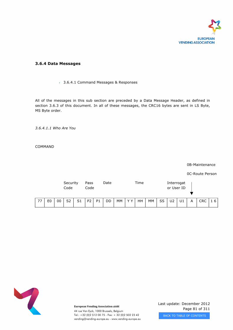
Last update: December 2012 Page 81 of 311
European Vending Association aisbl
44 rue Van Eyck, 1000 Brussels, Belgium Tel.: +32 (0)2 512 00 75 - Fax: + 32 (0)2 502 23 42 [email protected] - www.vending-europe.eu
3.6.4 Data Messages
› 3.6.4.1 Command Messages & Responses
All of the messages in this sub section are preceded by a Data Message Header, as defined in section 3.6.3 of this document. In all of these messages, the CRC16 bytes are sent in LS Byte, MS Byte order.
3.6.4.1.1 Who Are You
COMMAND
0B-Maintenance
0C-Route Person
Security Code
Pass Code
Date
Time Interrogator User ID
77 E0 00 S2 S1 P2 P1 DD MM Y Y HH MM SS U2 U1 A CRC 1 6
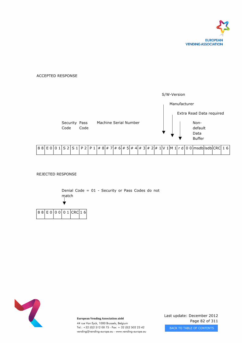
Last update: December 2012 Page 82 of 311
European Vending Association aisbl
44 rue Van Eyck, 1000 Brussels, Belgium Tel.: +32 (0)2 512 00 75 - Fax: + 32 (0)2 502 23 42 [email protected] - www.vending-europe.eu
ACCEPTED RESPONSE
S/W-Version
Manufacturer
Extra Read Data required
Security Code
Pass Code
Machine Serial Number
Non-default Data Buffer
8 8 E 0 0 1 S 2 S 1 P 2 P 1 # 8 # 7 # 6 # 5 # 4 # 3 # 2 # 1 V 1 M 1 r d 0 0 msdb lsdb CRC 1 6
REJECTED RESPONSE
Denial Code = 01 - Security or Pass Codes do not match
8 8 E 0 0 0 0 1 CRC 1 6
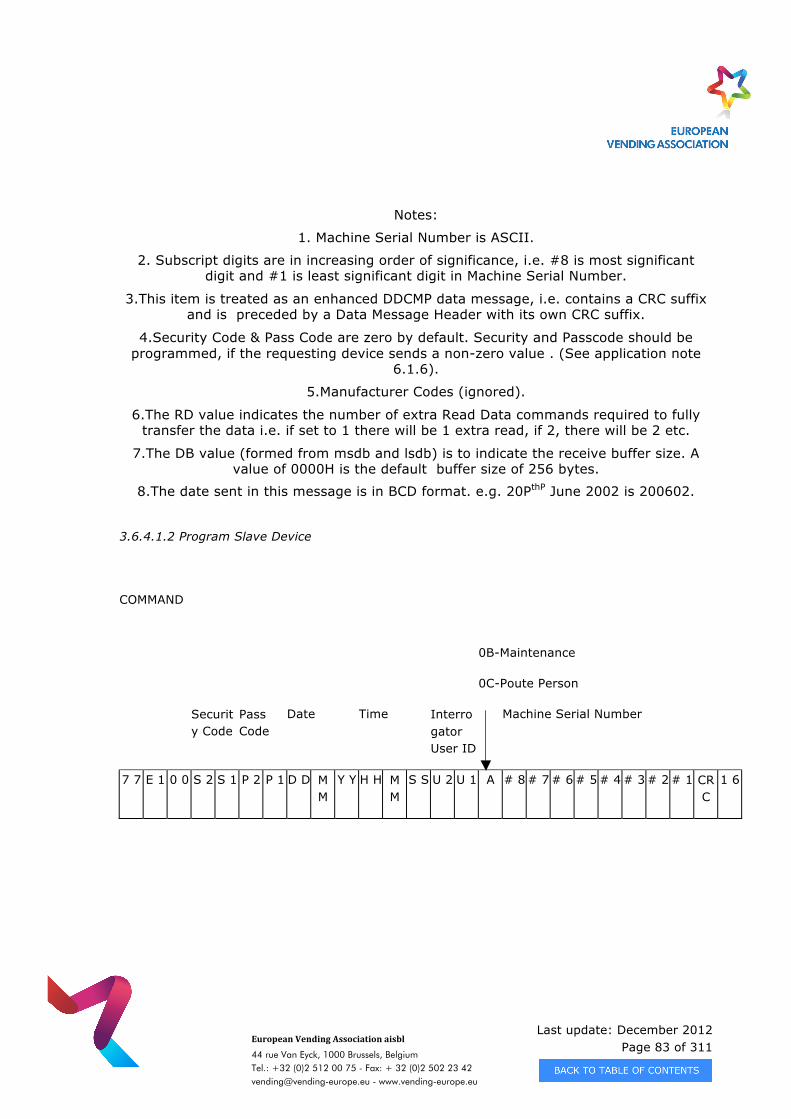
Last update: December 2012 Page 83 of 311
European Vending Association aisbl
44 rue Van Eyck, 1000 Brussels, Belgium Tel.: +32 (0)2 512 00 75 - Fax: + 32 (0)2 502 23 42 [email protected] - www.vending-europe.eu
Notes:
1. Machine Serial Number is ASCII.
2. Subscript digits are in increasing order of significance, i.e. #8 is most significant digit and #1 is least significant digit in Machine Serial Number.
3.This item is treated as an enhanced DDCMP data message, i.e. contains a CRC suffix and is preceded by a Data Message Header with its own CRC suffix.
4.Security Code & Pass Code are zero by default. Security and Passcode should be programmed, if the requesting device sends a non-zero value . (See application note
6.1.6).
5.Manufacturer Codes (ignored).
6.The RD value indicates the number of extra Read Data commands required to fully transfer the data i.e. if set to 1 there will be 1 extra read, if 2, there will be 2 etc.
7.The DB value (formed from msdb and lsdb) is to indicate the receive buffer size. A value of 0000H is the default buffer size of 256 bytes.
8.The date sent in this message is in BCD format. e.g. 20PthP June 2002 is 200602.
3.6.4.1.2 Program Slave Device
COMMAND
0B-Maintenance
0C-Poute Person
Security Code
Pass Code
Date Time Interrogator User ID
Machine Serial Number
7 7 E 1 0 0 S 2 S 1 P 2 P 1 D D M M
Y Y H H M M
S S U 2 U 1 A # 8 # 7 # 6 # 5 # 4 # 3 # 2 # 1 CRC
1 6
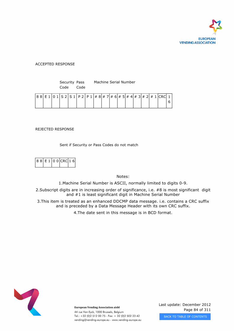
Last update: December 2012 Page 84 of 311
European Vending Association aisbl
44 rue Van Eyck, 1000 Brussels, Belgium Tel.: +32 (0)2 512 00 75 - Fax: + 32 (0)2 502 23 42 [email protected] - www.vending-europe.eu
ACCEPTED RESPONSE
Security Code
Pass Code
Machine Serial Number
8 8 E 1 0 1 S 2 S 1 P 2 P 1 # 8 # 7 # 6 # 5 # 4 # 3 # 2 # 1 CRC 1 6
REJECTED RESPONSE
Sent if Security or Pass Codes do not match
8 8 E 1 0 0 CRC 1 6
Notes:
1.Machine Serial Number is ASCII, normally limited to digits 0-9.
2.Subscript digits are in increasing order of significance, i.e. #8 is most significant digit and #1 is least significant digit in Machine Serial Number
3.This item is treated as an enhanced DDCMP data message. i.e. contains a CRC suffix and is preceded by a Data Message Header with its own CRC suffix.
4.The date sent in this message is in BCD format.
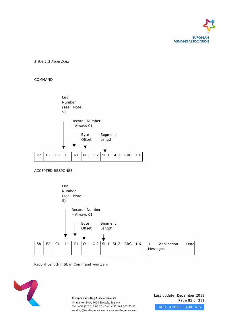
Last update: December 2012 Page 85 of 311
European Vending Association aisbl
44 rue Van Eyck, 1000 Brussels, Belgium Tel.: +32 (0)2 512 00 75 - Fax: + 32 (0)2 502 23 42 [email protected] - www.vending-europe.eu
3.6.4.1.3 Read Data
COMMAND
List Number (see Note 5)
Record Number – Always 01
Byte Offset
Segment Length
77 E2 00 L1 R1 O 1 O 2 SL 1 SL 2 CRC 1 6
ACCEPTED RESPONSE
List Number (see Note 5)
Record Number – Always 01
Byte Offset
Segment Length
88 E2 01 L1 R1 O 1 O 2 SL 1 SL 2 CRC 1 6 + Application Data Messages
Record Length if SL in Command was Zero
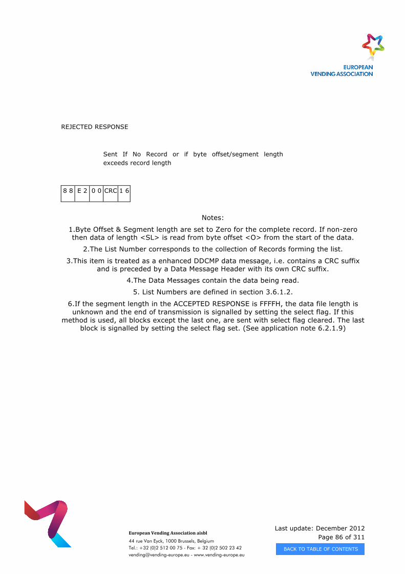
Last update: December 2012 Page 86 of 311
European Vending Association aisbl
44 rue Van Eyck, 1000 Brussels, Belgium Tel.: +32 (0)2 512 00 75 - Fax: + 32 (0)2 502 23 42 [email protected] - www.vending-europe.eu
REJECTED RESPONSE
Sent If No Record or if byte offset/segment length exceeds record length
8 8 E 2 0 0 CRC 1 6
Notes:
1.Byte Offset & Segment length are set to Zero for the complete record. If non-zero then data of length <SL> is read from byte offset <O> from the start of the data.
2.The List Number corresponds to the collection of Records forming the list.
3.This item is treated as a enhanced DDCMP data message, i.e. contains a CRC suffix and is preceded by a Data Message Header with its own CRC suffix.
4.The Data Messages contain the data being read.
5. List Numbers are defined in section 3.6.1.2.
6.If the segment length in the ACCEPTED RESPONSE is FFFFH, the data file length is unknown and the end of transmission is signalled by setting the select flag. If this
method is used, all blocks except the last one, are sent with select flag cleared. The last block is signalled by setting the select flag set. (See application note 6.2.1.9)
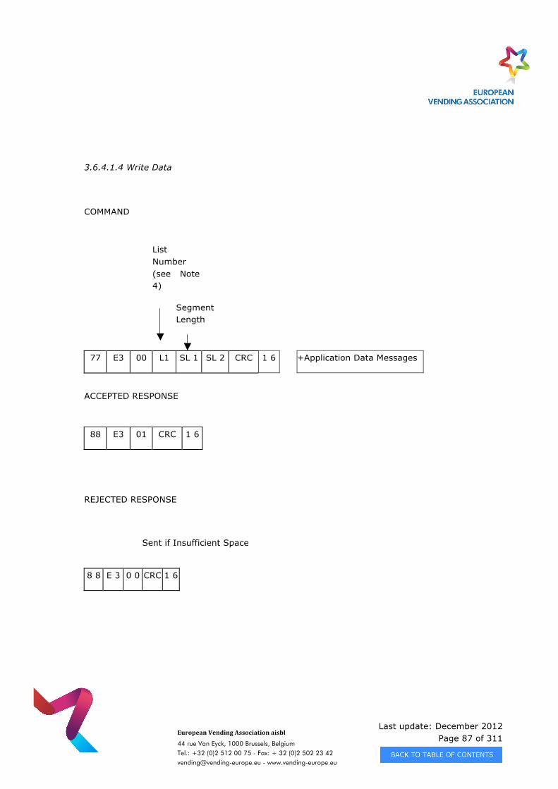
Last update: December 2012 Page 87 of 311
European Vending Association aisbl
44 rue Van Eyck, 1000 Brussels, Belgium Tel.: +32 (0)2 512 00 75 - Fax: + 32 (0)2 502 23 42 [email protected] - www.vending-europe.eu
3.6.4.1.4 Write Data
COMMAND
List Number (see Note 4)
Segment Length
77 E3 00 L1 SL 1 SL 2 CRC 1 6 +Application Data Messages
ACCEPTED RESPONSE
88 E3 01 CRC 1 6
REJECTED RESPONSE
Sent if Insufficient Space
8 8 E 3 0 0 CRC 1 6
Last update: December 2012 Page 88 of 311
European Vending Association aisbl
44 rue Van Eyck, 1000 Brussels, Belgium Tel.: +32 (0)2 512 00 75 - Fax: + 32 (0)2 502 23 42 [email protected] - www.vending-europe.eu
Notes:
1.The List Number corresponds to the collection of Records forming the list.
2.This item is treated as a enhanced DDCMP data message, i.e. contains a CRC suffix and is preceded by a Data Message Header with its own CRC suffix.
3.The Data Messages contain the data being written and are limited to 16365 bytes at a time.
4.List Numbers are defined in section 3.6.1.2.
5.If the segment length in the WRITE DATA COMMAND is FFFFH, the data file length is unknown and the end of transmission is signalled by setting the select flag. If this
method is used, all blocks except the last one, are sent with select flag cleared. The last block is signalled by setting the select flag set. (See application note 6.2.1.9)
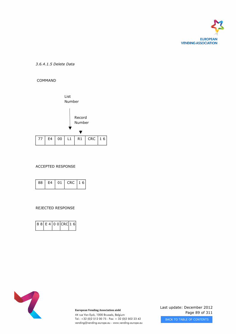
Last update: December 2012 Page 89 of 311
European Vending Association aisbl
44 rue Van Eyck, 1000 Brussels, Belgium Tel.: +32 (0)2 512 00 75 - Fax: + 32 (0)2 502 23 42 [email protected] - www.vending-europe.eu
3.6.4.1.5 Delete Data
COMMAND
List Number
Record Number
77 E4 00 L1 R1 CRC 1 6
ACCEPTED RESPONSE
88 E4 01 CRC 1 6
REJECTED RESPONSE
8 8 E 4 0 0 CRC 1 6
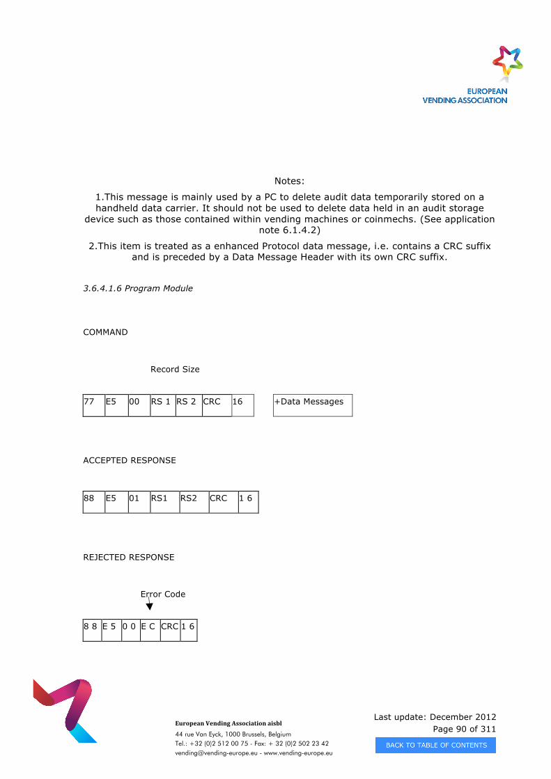
Last update: December 2012 Page 90 of 311
European Vending Association aisbl
44 rue Van Eyck, 1000 Brussels, Belgium Tel.: +32 (0)2 512 00 75 - Fax: + 32 (0)2 502 23 42 [email protected] - www.vending-europe.eu
Notes:
1.This message is mainly used by a PC to delete audit data temporarily stored on a handheld data carrier. It should not be used to delete data held in an audit storage
device such as those contained within vending machines or coinmechs. (See application note 6.1.4.2)
2.This item is treated as a enhanced Protocol data message, i.e. contains a CRC suffix and is preceded by a Data Message Header with its own CRC suffix.
3.6.4.1.6 Program Module
COMMAND
Record Size
77 E5 00 RS 1 RS 2 CRC 16 +Data Messages
ACCEPTED RESPONSE
88 E5 01 RS1 RS2 CRC 1 6
REJECTED RESPONSE
Error Code
8 8 E 5 0 0 E C CRC 1 6
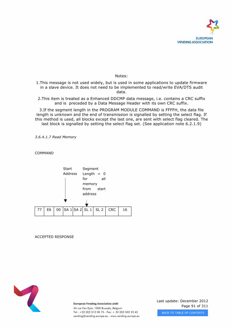
Last update: December 2012 Page 91 of 311
European Vending Association aisbl
44 rue Van Eyck, 1000 Brussels, Belgium Tel.: +32 (0)2 512 00 75 - Fax: + 32 (0)2 502 23 42 [email protected] - www.vending-europe.eu
Notes:
1.This message is not used widely, but is used in some applications to update firmware in a slave device. It does not need to be implemented to read/write EVA/DTS audit
data.
2.This item is treated as a Enhanced DDCMP data message, i.e. contains a CRC suffix and is preceded by a Data Message Header with its own CRC suffix.
3.If the segment length in the PROGRAM MODULE COMMAND is FFFFH, the data file length is unknown and the end of transmission is signalled by setting the select flag. If
this method is used, all blocks except the last one, are sent with select flag cleared. The last block is signalled by setting the select flag set. (See application note 6.2.1.9)
3.6.4.1.7 Read Memory
COMMAND
Start Address
Segment Length = 0 for all memory from start address
77 E6 00 SA 1 SA 2 SL 1 SL 2 CRC 16
ACCEPTED RESPONSE
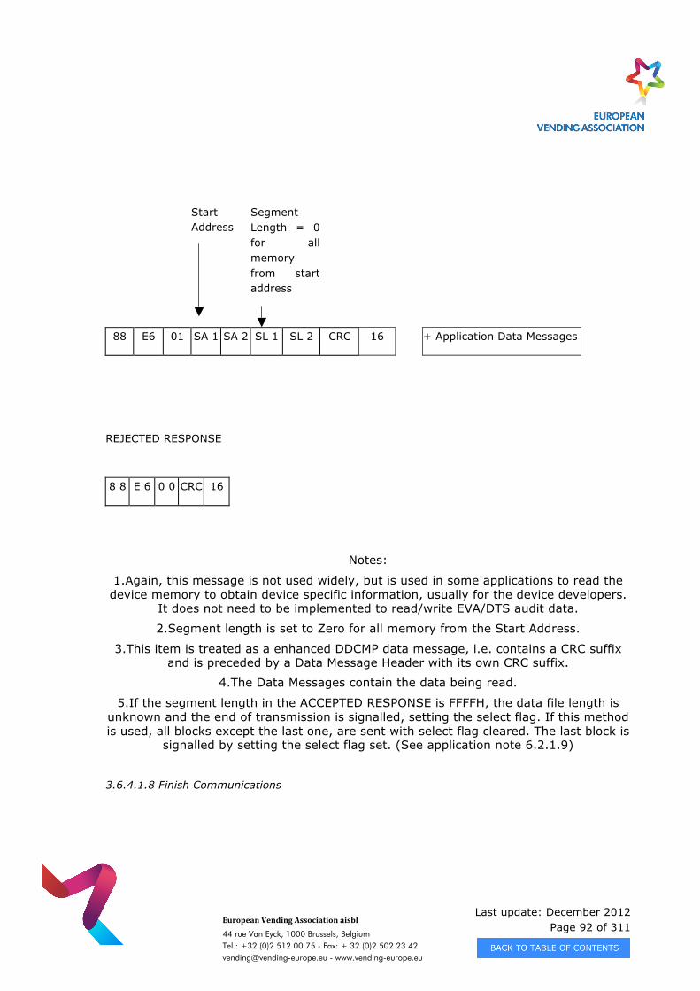
Last update: December 2012 Page 92 of 311
European Vending Association aisbl
44 rue Van Eyck, 1000 Brussels, Belgium Tel.: +32 (0)2 512 00 75 - Fax: + 32 (0)2 502 23 42 [email protected] - www.vending-europe.eu
Start Address
Segment Length = 0 for all memory from start address
88 E6 01 SA 1 SA 2 SL 1 SL 2 CRC 16 + Application Data Messages
REJECTED RESPONSE
8 8 E 6 0 0 CRC 16
Notes:
1.Again, this message is not used widely, but is used in some applications to read the device memory to obtain device specific information, usually for the device developers.
It does not need to be implemented to read/write EVA/DTS audit data.
2.Segment length is set to Zero for all memory from the Start Address.
3.This item is treated as a enhanced DDCMP data message, i.e. contains a CRC suffix and is preceded by a Data Message Header with its own CRC suffix.
4.The Data Messages contain the data being read.
5.If the segment length in the ACCEPTED RESPONSE is FFFFH, the data file length is unknown and the end of transmission is signalled, setting the select flag. If this method is used, all blocks except the last one, are sent with select flag cleared. The last block is
signalled by setting the select flag set. (See application note 6.2.1.9)
3.6.4.1.8 Finish Communications
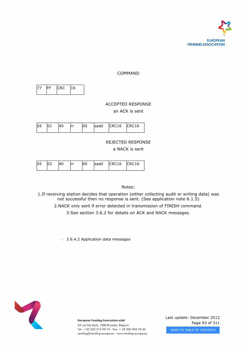
Last update: December 2012 Page 93 of 311
European Vending Association aisbl
44 rue Van Eyck, 1000 Brussels, Belgium Tel.: +32 (0)2 512 00 75 - Fax: + 32 (0)2 502 23 42 [email protected] - www.vending-europe.eu
COMMAND
77 FF CRC 16
ACCEPTED RESPONSE
an ACK is sent
05 01 40 rr 00 sadd CRC16 CRC16
REJECTED RESPONSE
a NACK is sent
05 02 40 rr 00 sadd CRC16 CRC16
Notes:
1.If receiving station decides that operation (either collecting audit or writing data) was not successful then no response is sent. (See application note 6.1.5)
2.NACK only sent if error detected in transmission of FINISH command.
3.See section 3.6.2 for details on ACK and NACK messages.
› 3.6.4.2 Application data messages
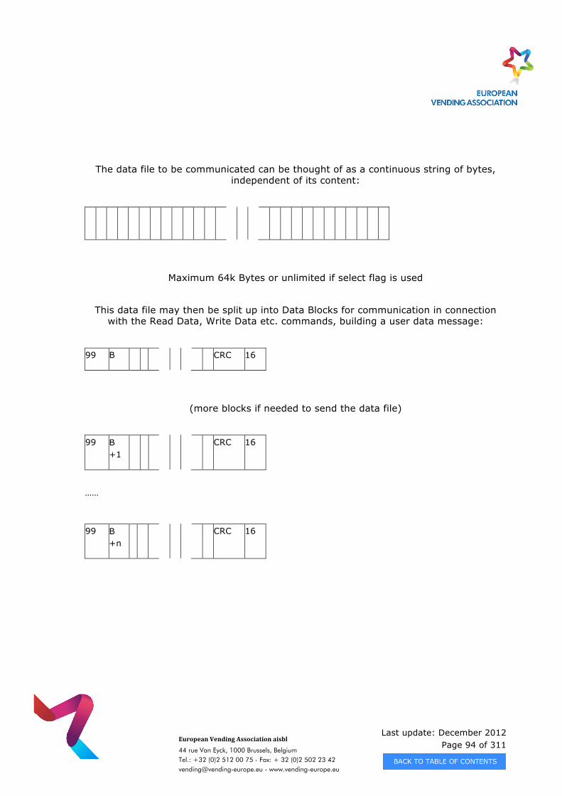
Last update: December 2012 Page 94 of 311
European Vending Association aisbl
44 rue Van Eyck, 1000 Brussels, Belgium Tel.: +32 (0)2 512 00 75 - Fax: + 32 (0)2 502 23 42 [email protected] - www.vending-europe.eu
The data file to be communicated can be thought of as a continuous string of bytes, independent of its content:
Maximum 64k Bytes or unlimited if select flag is used
This data file may then be split up into Data Blocks for communication in connection with the Read Data, Write Data etc. commands, building a user data message:
99 B CRC 16
(more blocks if needed to send the data file)
99 B +1
CRC 16
……
99 B +n
CRC 16
Last update: December 2012 Page 95 of 311
European Vending Association aisbl
44 rue Van Eyck, 1000 Brussels, Belgium Tel.: +32 (0)2 512 00 75 - Fax: + 32 (0)2 502 23 42 [email protected] - www.vending-europe.eu
B is Block Number (First block is block 0)
Data Bytes
Max. 16365 Bytes or less ( see chapter 3.6.3 )
Note: refer to 3.6.3. byte no 3
Each Data block is preceded by a message header, used to specify the block length. The data file length is given in the appropriate Read command, Write command, or by the
select flag.
3.6.5 Message Sequence
There are three fundamental message sequences in general usage within the Enhanced DDCMP described in this document:
Audit Collection with optional Configuration
Program Slave Device with optional Configuration
Security Collection
All of these are described in the Application Notes section for DDCMP.
Please note that the message sequence examples in the Application Notes section show how a message sequence is most often composed, but the defined commands (Read
Data, Write Data, Delete Data, etc.) are available and can be used in an arbitrary succession dependent on the purpose of the message sequence.
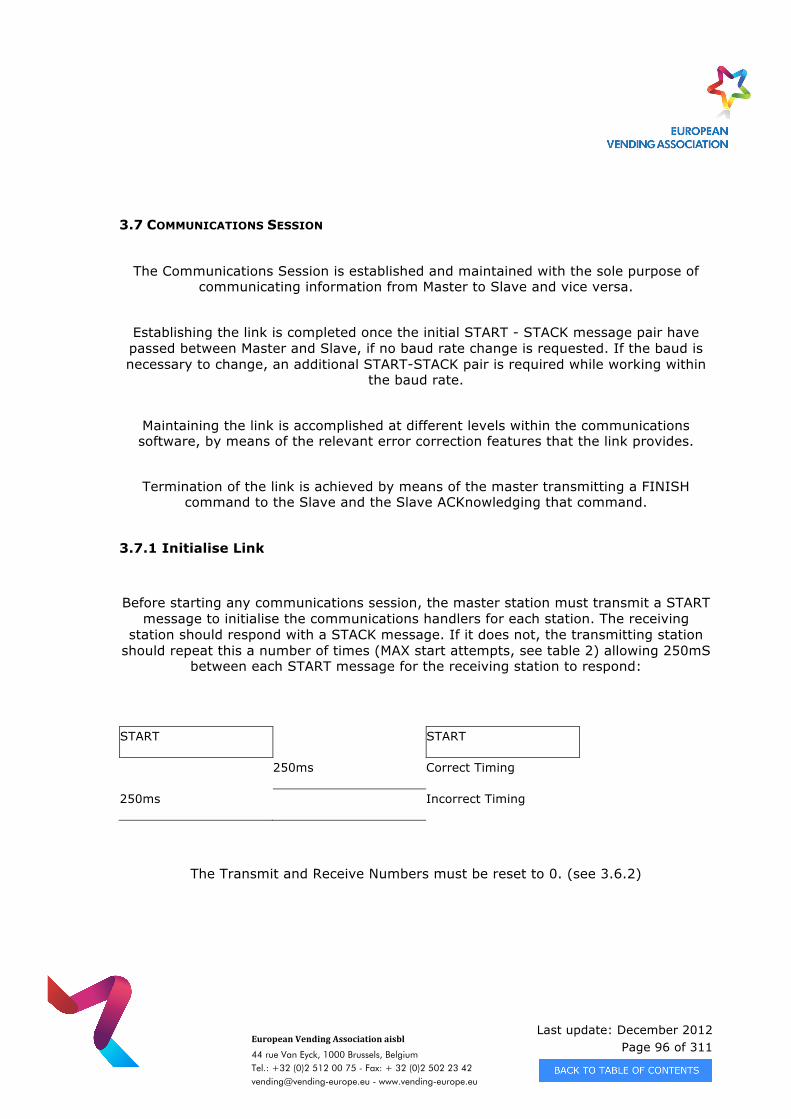
Last update: December 2012 Page 96 of 311
European Vending Association aisbl
44 rue Van Eyck, 1000 Brussels, Belgium Tel.: +32 (0)2 512 00 75 - Fax: + 32 (0)2 502 23 42 [email protected] - www.vending-europe.eu
3.7 COMMUNICATIONS SESSION
The Communications Session is established and maintained with the sole purpose of communicating information from Master to Slave and vice versa.
Establishing the link is completed once the initial START - STACK message pair have passed between Master and Slave, if no baud rate change is requested. If the baud is necessary to change, an additional START-STACK pair is required while working within
the baud rate.
Maintaining the link is accomplished at different levels within the communications software, by means of the relevant error correction features that the link provides.
Termination of the link is achieved by means of the master transmitting a FINISH command to the Slave and the Slave ACKnowledging that command.
3.7.1 Initialise Link
Before starting any communications session, the master station must transmit a START message to initialise the communications handlers for each station. The receiving
station should respond with a STACK message. If it does not, the transmitting station should repeat this a number of times (MAX start attempts, see table 2) allowing 250mS
between each START message for the receiving station to respond:
START START
250ms Correct Timing
250ms Incorrect Timing
The Transmit and Receive Numbers must be reset to 0. (see 3.6.2)
Last update: December 2012 Page 97 of 311
European Vending Association aisbl
44 rue Van Eyck, 1000 Brussels, Belgium Tel.: +32 (0)2 512 00 75 - Fax: + 32 (0)2 502 23 42 [email protected] - www.vending-europe.eu
3.7.2 Data Message Transfer
In the following sections, the Message Tx/Rx numbers refer to the numbers actually contained within the transmitted and received messages and the internal Tx/Rx numbers refer to the transmitting and receiving stations’ own internal counts, as
defined in section 3.5.1.2.
› 3.7.2.1 Transmitting station
The user data is encapsulated in a data message and assigned the next transmit message sequence number (Message Tx Number = Internal Tx Number).
Transmit the data message and wait for acknowledgement.
IF an ACK control message, a NACK control message or a data message is received successfully and the response sequence number matches the one for the transmitted
message (Message Rx Number = Tx Stn Transmit Number).
THEN Increment internal Tx Number (modulo 256). User software is informed of the successful transfer.
ELSEIF A corrupt message or an ACK/NACK/data message with non matching sequence numbers has been received.
THEN The data message is re-transmitted.
ELSEIF There has been no response within the ACK timeout period (table 2).
THEN The data message is re-transmitted.
ENDIF
(See application note 6.2.2.1 and Figure 5)
NOTE: If the transmitting station fails to transfer the message (i.e. Max data transfer attempts have been reached), it must still increment it’s internal Tx number. This prevents the next transmitted message appearing to be the same as the previous (failed) one. However, most of the time this would lead to a sequence error being
detected by the receiver (unless it happened to have received the previous message correctly despite the transmitter thinking it had failed) and the link would need to be
re-initialised to synchronise the sequence numbers.
(See application note 6.2.2.4)
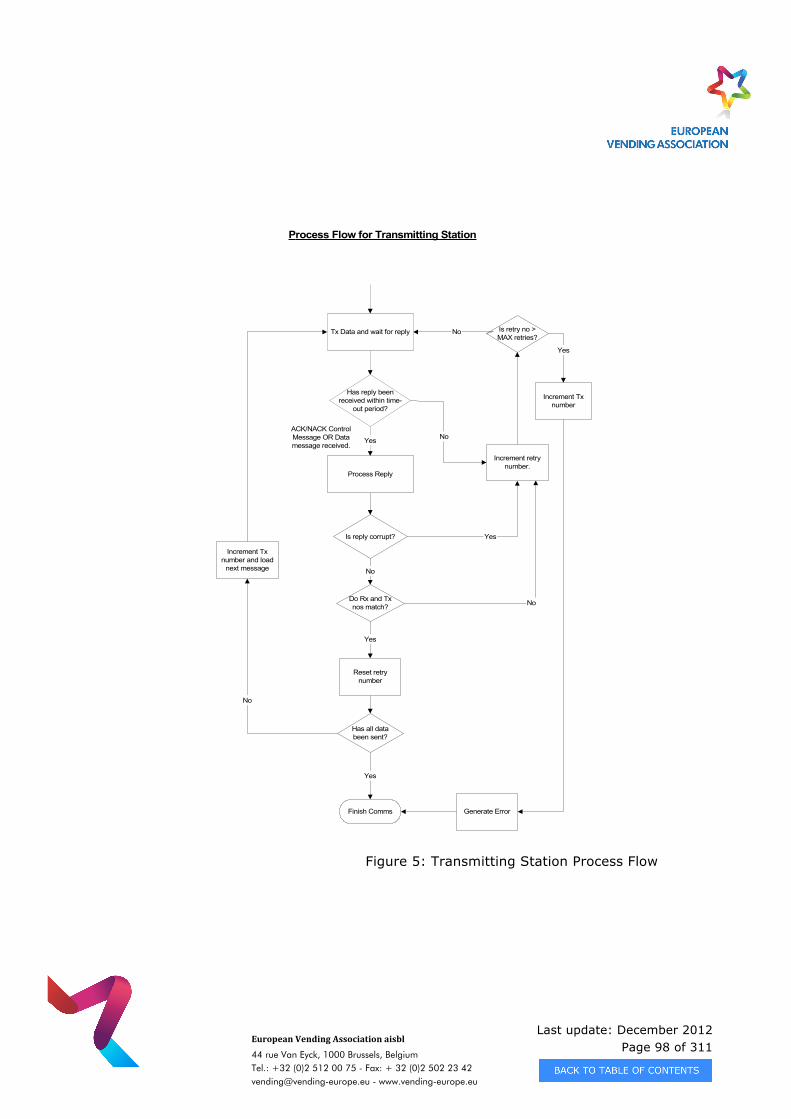
Last update: December 2012 Page 98 of 311
European Vending Association aisbl
44 rue Van Eyck, 1000 Brussels, Belgium Tel.: +32 (0)2 512 00 75 - Fax: + 32 (0)2 502 23 42 [email protected] - www.vending-europe.eu
Figure 5: Transmitting Station Process Flow
Is reply corrupt? Yes
Process Flow for Transmitting Station
ACK/NACK ControlMessage OR Datamessage received.
Process Reply
Tx Data and wait for reply
No
Do Rx and Txnos match? No
Yes
Has reply beenreceived within time-
out period?
Yes No
Increment Txnumber and load
next message
Has all databeen sent?
No
Finish Comms
Increment retrynumber.
Reset retrynumber
Is retry no >MAX retries?
No
Generate Error
Yes
Increment Txnumber
Yes
Last update: December 2012 Page 99 of 311
European Vending Association aisbl
44 rue Van Eyck, 1000 Brussels, Belgium Tel.: +32 (0)2 512 00 75 - Fax: + 32 (0)2 502 23 42 [email protected] - www.vending-europe.eu
› 3.7.2.2Receiving Station
IF The data message is received successfully, i.e. the block checks are valid and the message Tx number is the same as the next one expected (Message Tx Number =
Internal Rx Number)
THEN The Receive Number is incremented (modulo 256). An ACK control message containing the last received message sequence number is transmitted. The user
software is informed of the successful receipt.
ELSEIF No data message is received within a pre-defined period (Received data message/link timeout, table 2).
THEN The user software is informed that there is no message.
ELSEIF The data message is received but it is corrupt, the message sequence number is not as expected or the data is too long for the receiver’s buffer.
THEN a NACK control message containing the last successfully received message sequence number is transmitted.
ELSEIF a data message is received but it does not fulfil one of the above conditions
THEN The station ignores the message.
ENDIF
NOTE: If the transfer attempt fails and the maximum number of attempts has not been reached then the transfer is re-attempted. The receive data message time-out should
be set long enough to allow for the maximum attempts by the transmitter (see table 2).
(See
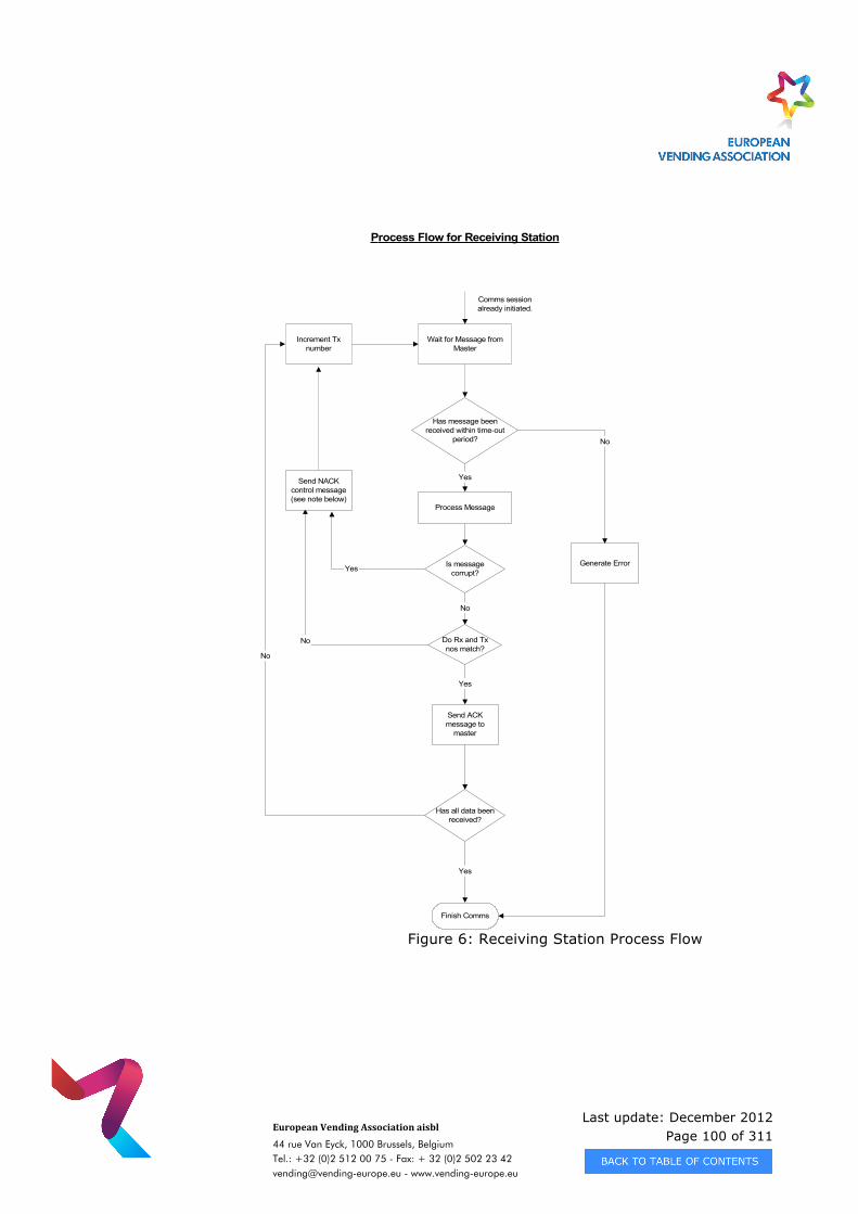
Last update: December 2012 Page 100 of 311
European Vending Association aisbl
44 rue Van Eyck, 1000 Brussels, Belgium Tel.: +32 (0)2 512 00 75 - Fax: + 32 (0)2 502 23 42 [email protected] - www.vending-europe.eu
Figure 6: Receiving Station Process Flow
Is messagecorrupt?Yes
Process Flow for Receiving Station
Process Message
Wait for Message fromMaster
No
Do Rx and Txnos match?
No
Yes
Has message beenreceived within time-out
period?
Yes
Increment Txnumber
Finish Comms
Send NACKcontrol message(see note below)
Generate Error
Yes
Comms sessionalready initiated.
Send ACKmessage to
master
Has all data beenreceived?
No
No
Last update: December 2012 Page 101 of 311
European Vending Association aisbl
44 rue Van Eyck, 1000 Brussels, Belgium Tel.: +32 (0)2 512 00 75 - Fax: + 32 (0)2 502 23 42 [email protected] - www.vending-europe.eu
Note 1 - Because the link is asynchronous, if the slave responds with a NACK, the master may still send the next message causing collisions on the optical bus. If this
occurs, the master will not receive the NACK, the slave will receive a corrupt message again, send a NACK and it could be possible to get into an infinite communications loop.
Because of this, the slave device should send the NACK only once for each corrupt message sequence and remain silent thereafter. (See application note 6.2.2.3)
3.7.3 Turn Around Time
There are two turn around times appropriate to the Enhanced DDCMP communications link, dependent on the activity taking place, transmission or reception.
When a unit is transmitting it must ensure that on completion of a transmission it is ready to receive within the minimum time consistent with the hardware used. Likewise when a unit is receiving, it must allow a period of time after the end of the last reception to ensure that it does not transmit before the receivers at the other end are ready. These turn around times are shown in table 2.
Last update: December 2012 Page 102 of 311
European Vending Association aisbl
44 rue Van Eyck, 1000 Brussels, Belgium Tel.: +32 (0)2 512 00 75 - Fax: + 32 (0)2 502 23 42 [email protected] - www.vending-europe.eu
CHAPTER 4 - DATA TRANSFER USING DEX/UCS
A monitored communication can be found in directory DEX/UCS Software on this CD-Rom.
4.1 SCOPE
This specification defines a direct connect (electrically hardwired) communications interface for the interchange of data between two units in the vending environment. The interface / protocol is based on the DEX/UCS communications standard that was developed by the Uniform Code Council, Inc. and various sponsoring associations of the US grocery store industry. The following Uniform Code Council (UCC) document may be obtained prior to implementing the direct connect vending system for more information and background on the UCC’s implementation. This chapter of the EVA-DTS provides details of the system for the vending industry. The actual DEX/UCS protocol specification for the interface implementation is provided by the UCC document. It should be noted that the document provides more information than is required by the vending interface. This chapter will reference the pertinent sections which are applicable. See Section 4.8 for additional details.
The previous EVA-DTS, up to and including Version 5.0, referenced the original UCC document published in 1989 and titled:
Uniform Communications Standards for Direct Store Delivery – Implementation and User Guide (UCS/DSD-IUG)
This version of the EVA-DTS references the latest UCC document version 004010UCS published in January, 1998 and titled:
UCS for Direct Store Delivery Implementation Guide (UCS/DSD)
Last update: December 2012 Page 103 of 311
European Vending Association aisbl
44 rue Van Eyck, 1000 Brussels, Belgium Tel.: +32 (0)2 512 00 75 - Fax: + 32 (0)2 502 23 42 [email protected] - www.vending-europe.eu
It is available from:
Uniform Code Council, Inc. 7887 Washington Village Drive, Suite 300 Dayton, Ohio 45459 (937) 435-3870 (800) 543-8137 (USA only) (937) 435-7317 (Fax) www.uc-council.org [email protected] (E-mail)
4.2 INTERFACE OVERVIEW
The vending direct connect interface standard has been adapted from the DEX/UCS standard to directly link two electronic devices together for transferring vending audit or configuration data. Examples of vending audit data are the amount of cash accepted / dispensed, the amount and number of vend / product transactions, the number and/or times of events, etc. Examples of configuration data are setting prices, device asset numbers, time/date, etc. The medium for the vending audit or configuration data transfer is based on the DEX/UCS fixed communications protocol and physical interface. The actual data records that are transferred follow the format of the DEX/UCS Delivery/Return Base Records; however, those records were intended for the US grocery industry. The details of the data records unique to the vending environment are found in the Data Dictionary (Appendix A) of the EVA Data Transfer Standard.
Throughout this chapter reference will be made to three specific types of electronic devices as defined below: Vending Machine Device (VMD) - refers to the actual device in the vending
machine that monitors the various transactions and assimilates the audit data. This device may also be able to be configured using the DEX/UCS protocol. Examples of targets are vending machine control boards, coin mechanisms, cashless readers, audit devices, etc.
Data Carrier (DC) - refers to the actual device that interrogates or configures the
VMD using DEX/UCS. Examples are hand held terminals, portable computers, radio telemetry systems, cellular systems, etc.
Last update: December 2012 Page 104 of 311
European Vending Association aisbl
44 rue Van Eyck, 1000 Brussels, Belgium Tel.: +32 (0)2 512 00 75 - Fax: + 32 (0)2 502 23 42 [email protected] - www.vending-europe.eu
Business System Computer (BSC) - refers to the higher level computer system that the DCs upload with their collected data from the VMD or receive configuration/setup information. Examples are mainframes, minis, personal computers, etc. It should be noted that it is not a requirement that the DC to BSC interface be implemented via the standard DEX/UCS interface. Numerous proprietary and open means of transferring data between the DC and BSC exist worldwide in the industry.
The DEX/UCS communications protocol follows a four level (layer) approach similar in form to the International Standards Organization (ISO) "Open Systems Interconnection." The following subsections provide an overview of the DEX/UCS protocol starting with the lowest level of the four layers.
4.3 PHYSICAL LEVEL DETAILS
(ref: UCS/DSD Chapter VII Physical Level) Please refer to EVA-DTS Chapter 7.
Earlier versions of this specification allowed for some other method of initiating the DEX/UCS transfer in the VMD (i.e., a pushbutton) if automatic detect was not performed. It is the recommendation of NAMA and the EVA that for new designs after July, 2002, no manual means of initiating an audit data transfer be permitted in a VMD. This is especially important for unattended sites with remote access. In these cases, communications must be able to be started without manual intervention. DEX transmissions must be able to be established with the vending machine door either open or closed. This is again especially true for unattended sites with remote access.
4.4 DATA LINK LEVEL DETAILS
(ref: UCS/DSD Chapter VII Data Link Level)
(ref: UCS/DSD Appendix B)
The details of the DEX/UCS Data Link Level are thoroughly defined in the UCS/DSD Chapter VII titled "DATA LINK LEVEL" and Appendix B titled "CRC GENERATION." The Data Link Level describes the actual serial communications parameters of the interface.
Last update: December 2012 Page 105 of 311
European Vending Association aisbl
44 rue Van Eyck, 1000 Brussels, Belgium Tel.: +32 (0)2 512 00 75 - Fax: + 32 (0)2 502 23 42 [email protected] - www.vending-europe.eu
The implementation by the vending industry follows these sections explicitly and no further clarification is required.
Transmission Timing, Speed, and Format: The actual data communications is based on an asynchronous, half duplex serial interface operating with the characteristics of a 9600 bits per second transfer rate, eight bit bytes, no parity. The data bytes are based on the seven bit ASCII character set with the exception of the CRC-16 integrity bytes which use the full eight bits. Allowable Characters: Except for the two byte block check CRC-16, all characters sent via DEX/UCS shall be the lower 127 ASCII characters (00h to 7Eh). Specific control characters and combinations that are permitted are:
01h SOH 0Ah LF 10h 30h DLE 0 (ACK 0) 02h STX 0Dh CR 10h 31h DLE 1 (ACK 1) 03h ETX 10h DLE 10h 3Bh DLE ; (WACK) 04h EOT 15h NAK 05h ENQ 16h SYN 17h ETB
All printable characters (20h to 7Eh) are permitted for use in alphanumeric elements with the exception of an asterisk (*) which is used as a data element delimiter. Flow Control: No hardware or software (XON/XOFF) flow control is provided. Message transfer and blocking protocol: Message transfer control on a data block basis is provided by the procedures outlined in the Message Transfer Blocking Protocol section of the UCS/DSD Chapter VII which provides for blocking that is independent of message content. Block Size: All data records are sent as variable length data blocks with an individual maximum size of 245 bytes. The (up to) 245 byte block is defined as that data following the DLE STX and continuing through and including the DLE ETB or DLE ETX. The CRC-16 is not included.
Block Cyclic Redundancy Check (CRC-16): The block CRC-16 is a 16-bit character generated by applying a specified algorithm to the contents of the transmission block. The CRC-16 is sent as two 8-bit bytes with the least significant byte sent first and the most significant byte sent second. In essence, if the CRC-16 had a value of 1234h, the
Last update: December 2012 Page 106 of 311
European Vending Association aisbl
44 rue Van Eyck, 1000 Brussels, Belgium Tel.: +32 (0)2 512 00 75 - Fax: + 32 (0)2 502 23 42 [email protected] - www.vending-europe.eu
block CRC would be sent as 34h 12h. Note that this is the opposite order that the G85 CRC is transmitted (see Chapter 2.4.3).
The block CRC-16 is calculated starting with (and including) the first byte after the STX and ending with (and including) the ETB or ETX. Note that it will exclude any DLE or SYN control characters. For an explanation of the CRC-16 algorithm see Appendix B of the UCS/DSD Implementation Guide.
4.5 SESSION LEVEL DETAILS
(ref: UCS/DSD Chapter VII Session Level)
The procedures for the establishment and termination of the communication session is based on the Establishment and Termination section of the UCS/DSD Chapter VII Session Level. This section defines the communications protocol where two directly connected devices (non-switched, point-to-point) may bid for master status. The ability to bid for master status provides the capability for transferring data in either direction between the two devices.
However, as of July, 2002, it is the recommendation of NAMA and the EVA that all VMDs that are able to be configured (i.e. vending machine control boards, coin mechanisms that hold prices, etc.) do not bid for master status except when reporting errors or other critcal events. These VMDs should assume slave status at the initiation of the DEX transfer in order for the DC to direct the VMD as to whether audit information is to be read or configuration information is to be sent. The details of the DEX/UCS Session Level are thoroughly defined in the UCS/DSD Chapter VII titled "SESSION LEVEL". The Session Level describes the three consecutive parts of the data transfer:
First Handshake Session Level Second Handshake Session Level Data Record Transfer Session & Application Level
The following subsections are provided to highlight exceptions and provide further clarification for the vending industry.
Last update: December 2012 Page 107 of 311
European Vending Association aisbl
44 rue Van Eyck, 1000 Brussels, Belgium Tel.: +32 (0)2 512 00 75 - Fax: + 32 (0)2 502 23 42 [email protected] - www.vending-europe.eu
4.5.1 Vending Machine Session Establishment
Prior to the three sessions occurring, the physical direct connection and the establishment of which device assumes MASTER status must occur. MASTER status implies which device starts the first Handshake. The interrogation of the VMD by the Data Carrier (DC) falls into the category of an unattended interchange (reference UCS/DSD Chapter VII Session Level Establishment and Termination section, "Contention for Master Status”). Although the DC plugs into or electrically connects to the VMD , the vending industry initially made an exception to the DEX/UCS specification and elected to have the VMD assume MASTER status for the First Handshake. This has been done for all current production coin mechanisms and most pre Multi-Drop Bus (MDB) vending machine controllers.
Most current generation vending machines controllers (primarily, but not limited to Multi-Drop Bus (MDB) controllers) assume the SLAVE status for the First Handshake. This has been done to allow the DC, as MASTER, to select the direction of data transfer to either retrieve audit data or transfer configuration/setup parameters. With the introduction of real time telemetry systems, it has become optional for vending machine controllers to initiate a data transfer when an error or some other unique event occurs. This will allow the telemetry system to “immediately” notify the host system regarding the abnormal situation. The method for doing this will be for the vending machine controller to assume MASTER status for the First Handshake. Once the session is established, the controller will transfer the EA1 and/or EA2 event based data elements. It is up to the system design of the telemetry system to process the data further. The two types of VMD session establishment place a requirement on the DCs to determine if it will become a MASTER or SLAVE for the First Handshake per below: The DC, when connecting to a MASTER status VMD must allow for the first ENQs to be transmitted automatically from the VMD. Assuming the DC is capable of full-duplex communications, receipt of the VMD’s ENQ prior to its ENQ transmission should result in the DC aborting its transmission and becoming an instant SLAVE. Otherwise, if the DC transmits its ENQ prior to or simultaneously with the VMD’s, the VMD may miss the ENQ if half-duplex or throw it away if full-duplex. Regardless, the VMD will retransmit another ENQ and await the required DLE 0 (ACK 0) response. The DC, upon receiving the VMD’s second ENQ should revert back to SLAVE status and continue with the First Handshake. Following the physical connection and master/slave establishment, the actual three part data transmission will occur. This data interchange will adhere to the definitions of the referenced DEX/UCS documents.
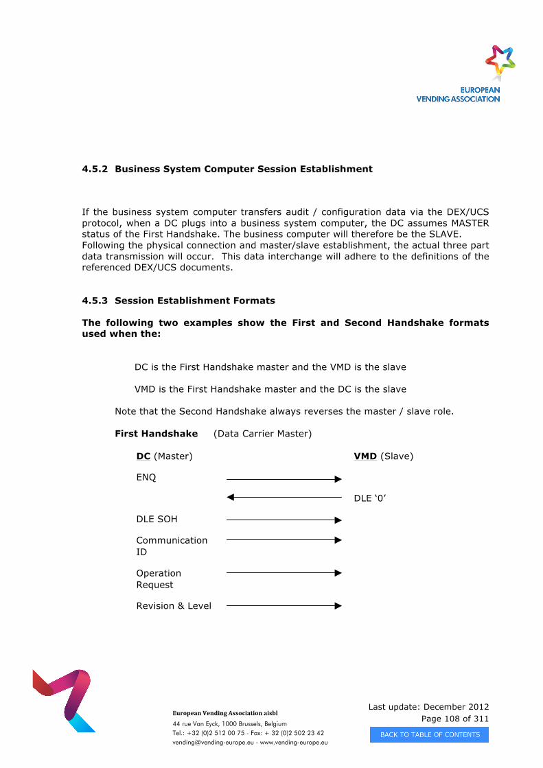
Last update: December 2012 Page 108 of 311
European Vending Association aisbl
44 rue Van Eyck, 1000 Brussels, Belgium Tel.: +32 (0)2 512 00 75 - Fax: + 32 (0)2 502 23 42 [email protected] - www.vending-europe.eu
4.5.2 Business System Computer Session Establishment
If the business system computer transfers audit / configuration data via the DEX/UCS protocol, when a DC plugs into a business system computer, the DC assumes MASTER status of the First Handshake. The business computer will therefore be the SLAVE. Following the physical connection and master/slave establishment, the actual three part data transmission will occur. This data interchange will adhere to the definitions of the referenced DEX/UCS documents.
4.5.3 Session Establishment Formats
The following two examples show the First and Second Handshake formats used when the:
DC is the First Handshake master and the VMD is the slave VMD is the First Handshake master and the DC is the slave
Note that the Second Handshake always reverses the master / slave role.
First Handshake (Data Carrier Master)
DC (Master) VMD (Slave)
ENQ
DLE ‘0’
DLE SOH
Communication ID
Operation Request
Revision & Level
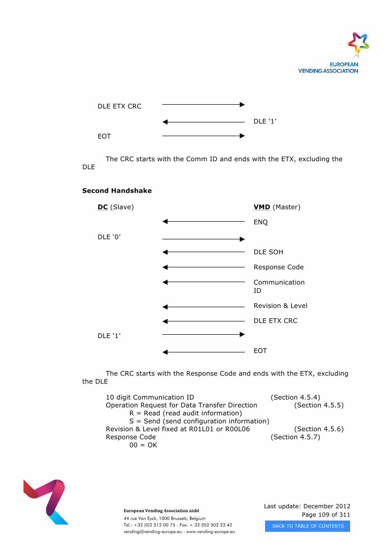
Last update: December 2012 Page 109 of 311
European Vending Association aisbl
44 rue Van Eyck, 1000 Brussels, Belgium Tel.: +32 (0)2 512 00 75 - Fax: + 32 (0)2 502 23 42 [email protected] - www.vending-europe.eu
DLE ETX CRC
DLE ‘1’
EOT
The CRC starts with the Comm ID and ends with the ETX, excluding the DLE Second Handshake
DC (Slave) VMD (Master)
ENQ
DLE ‘0’
DLE SOH
Response Code
Communication ID
Revision & Level
DLE ETX CRC
DLE ‘1’
EOT
The CRC starts with the Response Code and ends with the ETX, excluding
the DLE
10 digit Communication ID (Section 4.5.4) Operation Request for Data Transfer Direction (Section 4.5.5) R = Read (read audit information) S = Send (send configuration information) Revision & Level fixed at R01L01 or R00L06 (Section 4.5.6) Response Code (Section 4.5.7) 00 = OK
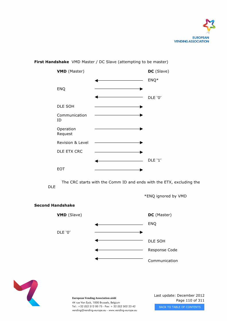
Last update: December 2012 Page 110 of 311
European Vending Association aisbl
44 rue Van Eyck, 1000 Brussels, Belgium Tel.: +32 (0)2 512 00 75 - Fax: + 32 (0)2 502 23 42 [email protected] - www.vending-europe.eu
First Handshake VMD Master / DC Slave (attempting to be master)
VMD (Master) DC (Slave)
ENQ*
ENQ
DLE ‘0’
DLE SOH
Communication ID
Operation Request
Revision & Level
DLE ETX CRC
DLE ‘1’
EOT
The CRC starts with the Comm ID and ends with the ETX, excluding the
DLE
*ENQ ignored by VMD
Second Handshake
VMD (Slave) DC (Master)
ENQ
DLE ‘0’
DLE SOH
Response Code
Communication
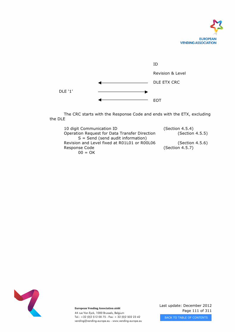
Last update: December 2012 Page 111 of 311
European Vending Association aisbl
44 rue Van Eyck, 1000 Brussels, Belgium Tel.: +32 (0)2 512 00 75 - Fax: + 32 (0)2 502 23 42 [email protected] - www.vending-europe.eu
ID
Revision & Level
DLE ETX CRC
DLE ‘1’
EOT
The CRC starts with the Response Code and ends with the ETX, excluding
the DLE
10 digit Communication ID (Section 4.5.4) Operation Request for Data Transfer Direction (Section 4.5.5) S = Send (send audit information) Revision and Level fixed at R01L01 or R00L06 (Section 4.5.6) Response Code (Section 4.5.7)
00 = OK
Last update: December 2012 Page 112 of 311
European Vending Association aisbl
44 rue Van Eyck, 1000 Brussels, Belgium Tel.: +32 (0)2 512 00 75 - Fax: + 32 (0)2 502 23 42 [email protected] - www.vending-europe.eu
4.5.4 Communication IDs
(ref: UCS/DSD Chapter VII Session Level)
During the First and Second Handshake the connected devices will transmit their respective Communication IDs. These IDs are ten alphanumeric characters which are either:
- the upper six (6) digits as assigned by the Uniform Code Council to uniquely identify each manufacturer. The lower four (4) digits are assigned by the manufacturer and can be varied as desired.
Or - the upper three (3) characters are the manufacturer code as specified in
Appendix B. The lower seven (7) digits are assigned by the manufacturer and can be varied as desired. This method will be mandatory for all Version 6.0 and higher devices.
4.5.5 Operation Request
(ref: UCS/DSD Chapter VII Session Level)
The vending industry has adopted the “S” (Send) and “R” (Read) operation request designators and an “M” (Manufacturer Specific State) with the following definitions: Data Carrier (DC) is Master for First Handshake
“S” = Request to send configuration data to VMD “R” = Request to read audit data from VMD “M” = Request to enter a Manufacturer Specific State
Version 6.0 has added the “M” operation request code that would be sent by the Master and interpreted by VMDs that are First Handshake Slaves to go into a manufacturer specific state following the completion of the Second Handshake with the “OK” response code (00). This allows Data Carriers (and/or manufacturing test equipment) to switch the VMD into a special state. This state is intended for non DEX/UCS communications and should only be used for hardware parameter setups, diagnostics, test-modes, FLASH memory downloads, etc.
Last update: December 2012 Page 113 of 311
European Vending Association aisbl
44 rue Van Eyck, 1000 Brussels, Belgium Tel.: +32 (0)2 512 00 75 - Fax: + 32 (0)2 502 23 42 [email protected] - www.vending-europe.eu
Normal DEX/UCS cash and/or product setups must still be performed through the configuration data records as outlined in the Data Dictionary (Appendix A). The individual manufacturers shall determine their own serial communications parameters and protocols once the manufacture specific state is entered.
Vending Machine Device (VMD) is Master for First Handshake
“S” = Request to send data to DC
4.5.6 Revision & Level
(ref: UCS/DSD Chapter VII Session Level)
The vending industry initially adopted the single revision (R01) and level (L01) standard for the initial DEX/UCS implementation. Systems implementing the requirements of the EVA-DTS Version 6.0 and above should use the DTS version tracking number, e.g. DTS Version 6.0 would be revision 0 (R00) and level 6 (L06).
4.5.7 Response Codes
(ref: UCS/DSD Chapter VII Session Level)
During the Second Handshake, the Master device (Slave in the First Handshake) will send a Response Code. This code will determine whether or not the actual data transfer will take place. Although seven codes are defined (00 to 05, & 90) most vending applications only use Response Code 00 (OK).
00 = OK (to transfer data)
01 = Unrecognized Communication ID
02 = Unsupported Revision & Level
03 = Operation conflict, try again
04 = No data to transfer
05 = Undefined error
90 = Manufacturer Specific State
Last update: December 2012 Page 114 of 311
European Vending Association aisbl
44 rue Van Eyck, 1000 Brussels, Belgium Tel.: +32 (0)2 512 00 75 - Fax: + 32 (0)2 502 23 42 [email protected] - www.vending-europe.eu
The vending industry has added a seventh code (90) which would be interpreted by VMDs that are First Handshake Masters to go into a manufacturer specific state following the completion of the Second Handshake. This allows Data Carriers (and/or manufacturing test equipment) to switch the VMD into a special state. This state is intended for non DEX/UCS communications and should only be used for hardware parameter setups, diagnostics, test-modes, etc.
Normal DEX/UCS cash and/or product setups must still be performed through the configuration data records as outlined in the Data Dictionary (Appendix A). The individual manufacturers shall determine their own serial communications parameters and protocols once the manufacture specific state is entered. 4.5.8 Timers and Limits
(ref: UCS/DSD Chapter VII Session Level)
All timer and limit definitions as specified in the referenced DEX/UCS documents shall apply and must be consulted for complete specifications. Additional timing requirements are listed below and are recommended for all new designs after July, 2002. Response time: Before responding to an ENQ, data block, or any other transmitted control character (DLE 0/1 (ACK 0/1), NAK, etc.), the responding unit should wait a minimum of 10 milliseconds before answering back. Some devices can only operate in half-duplex mode and require a short period of time to switch over from send to receive. If the response is too quick, it may be received before the switch over is complete and be missed.
Intersession pause: As stated in Section 4.5, the DEX/UCS data transmission process consists of three consecutive sessions – two handshake sessions and one data exchange session. Before initiating the second or third session, the initiating device should pause a minimum of 100 milliseconds to avoid confusion in processing control characters associated with the end of one session and the beginning of the next.
Timer A margin: The sending device uses Timer A to protect against an invalid or no response from the receiving device. Upon sending an ENQ or completing the transmission of a block, the sending device starts Timer A (1 second) and then waits for the proper response. To provide margin, the receiving device should respond within no greater than 950 milliseconds.
Last update: December 2012 Page 115 of 311
European Vending Association aisbl
44 rue Van Eyck, 1000 Brussels, Belgium Tel.: +32 (0)2 512 00 75 - Fax: + 32 (0)2 502 23 42 [email protected] - www.vending-europe.eu
If the receiving device cannot be ready with the normal response within the Timer A period, it can respond with a wait acknowledge represented by a WACK (DLE ;). To again provide margin, the receiving device should not wait the full second before responding with the WACK. It should instead respond back within 950 milliseconds.
Upon receiving the WACK, the sending device should wait between100 to 500 milliseconds before sending the next ENQ to continue the data transfer process.
Timer B margin: The receiving device uses Timer B (100 milliseconds) to protect against the non-recognition of a block terminating character by the sending device. If the sending device wishes to pause while sending data, it should periodically (every 90 milliseconds or less) send TSYN (DLE SYN) characters as fillers. This will avoid a Timer B time-out.
Timer C margin: The DEX/UCS protocol does not use Timer C.
Timer D margin: Both the sending and receiving devices use Timer D (2 seconds) to protect against no activity during the First Handshake, the Second Handshake, or the Data Transfer. To provide for margin, it is recommended that devices wait at least 2.1 to 2.2 seconds before detecting a Timer D timeout situation.
Timer “O”: It should be noted that Timer D is not an overall DEX timer and does not apply to the idle time before the First Handshake, the Second Handshake, or the Data Transfer. These times are specified as “indefinite”. In essence, there could be an infinite amount of time between the DEX plug being inserted and the First Handshake, between the end of the First Handshake and the start of the Second Handshake, or between the end of the Second Handshake and the start of the Data Transfer.
To prevent against a vending system hang, it is recommended that VMDs initiate an overall non-activity timer of 60 seconds. This would start when the DEX plug is inserted (or electrically connected) or communication is established and would be restarted each time a character is transmitted or received. If this overall timeout is reached, the VMD should revert back to its normal vending functions.
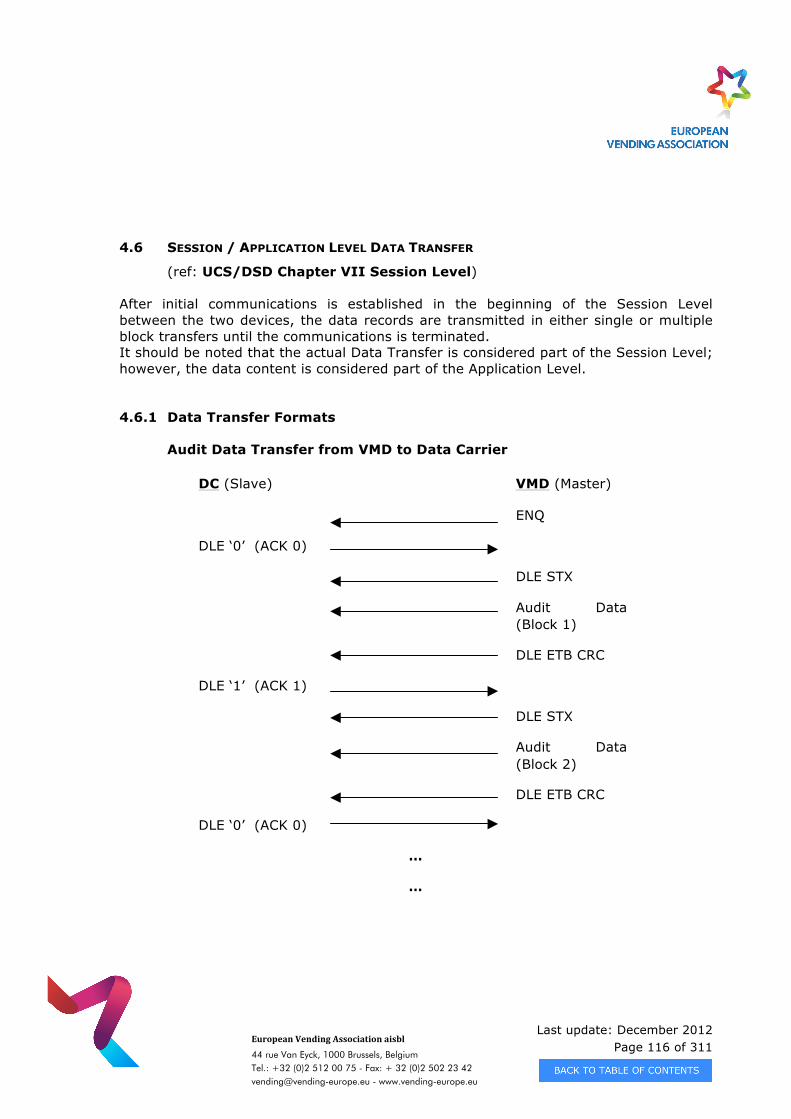
Last update: December 2012 Page 116 of 311
European Vending Association aisbl
44 rue Van Eyck, 1000 Brussels, Belgium Tel.: +32 (0)2 512 00 75 - Fax: + 32 (0)2 502 23 42 [email protected] - www.vending-europe.eu
4.6 SESSION / APPLICATION LEVEL DATA TRANSFER
(ref: UCS/DSD Chapter VII Session Level)
After initial communications is established in the beginning of the Session Level between the two devices, the data records are transmitted in either single or multiple block transfers until the communications is terminated. It should be noted that the actual Data Transfer is considered part of the Session Level; however, the data content is considered part of the Application Level.
4.6.1 Data Transfer Formats Audit Data Transfer from VMD to Data Carrier
DC (Slave) VMD (Master)
ENQ
DLE ‘0’ (ACK 0)
DLE STX
Audit Data (Block 1)
DLE ETB CRC
DLE ‘1’ (ACK 1)
DLE STX
Audit Data (Block 2)
DLE ETB CRC
DLE ‘0’ (ACK 0)
…
…
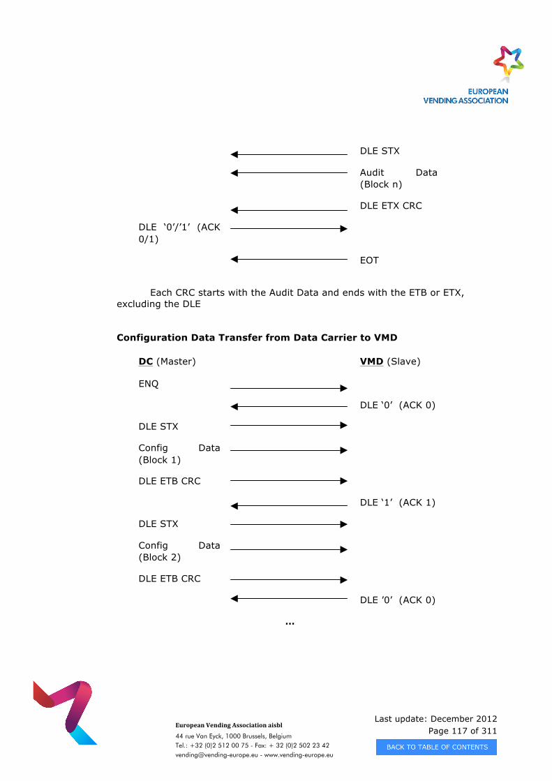
Last update: December 2012 Page 117 of 311
European Vending Association aisbl
44 rue Van Eyck, 1000 Brussels, Belgium Tel.: +32 (0)2 512 00 75 - Fax: + 32 (0)2 502 23 42 [email protected] - www.vending-europe.eu
DLE STX
Audit Data (Block n)
DLE ETX CRC
DLE ‘0’/’1’ (ACK 0/1)
EOT
Each CRC starts with the Audit Data and ends with the ETB or ETX,
excluding the DLE Configuration Data Transfer from Data Carrier to VMD
DC (Master) VMD (Slave)
ENQ
DLE ‘0’ (ACK 0)
DLE STX
Config Data (Block 1)
DLE ETB CRC
DLE ‘1’ (ACK 1)
DLE STX
Config Data (Block 2)
DLE ETB CRC
DLE ’0’ (ACK 0)
…
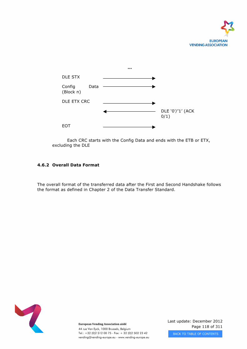
Last update: December 2012 Page 118 of 311
European Vending Association aisbl
44 rue Van Eyck, 1000 Brussels, Belgium Tel.: +32 (0)2 512 00 75 - Fax: + 32 (0)2 502 23 42 [email protected] - www.vending-europe.eu
…
DLE STX
Config Data (Block n)
DLE ETX CRC
DLE ‘0’/’1’ (ACK 0/1)
EOT
Each CRC starts with the Config Data and ends with the ETB or ETX,
excluding the DLE
4.6.2 Overall Data Format
The overall format of the transferred data after the First and Second Handshake follows the format as defined in Chapter 2 of the Data Transfer Standard.
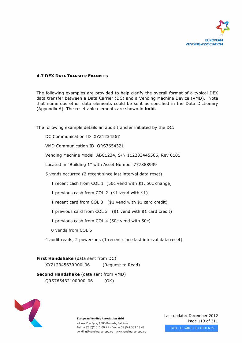
Last update: December 2012 Page 119 of 311
European Vending Association aisbl
44 rue Van Eyck, 1000 Brussels, Belgium Tel.: +32 (0)2 512 00 75 - Fax: + 32 (0)2 502 23 42 [email protected] - www.vending-europe.eu
4.7 DEX DATA TRANSFER EXAMPLES
The following examples are provided to help clarify the overall format of a typical DEX data transfer between a Data Carrier (DC) and a Vending Machine Device (VMD). Note that numerous other data elements could be sent as specified in the Data Dictionary (Appendix A). The resettable elements are shown in bold.
The following example details an audit transfer initiated by the DC:
DC Communication ID XYZ1234567
VMD Communication ID QRS7654321
Vending Machine Model ABC1234, S/N 112233445566, Rev 0101
Located in “Building 1” with Asset Number 777888999
5 vends occurred (2 recent since last interval data reset)
1 recent cash from COL 1 (50c vend with $1, 50c change)
1 previous cash from COL 2 ($1 vend with $1)
1 recent card from COL 3 ($1 vend with $1 card credit)
1 previous card from COL 3 ($1 vend with $1 card credit)
1 previous cash from COL 4 (50c vend with 50c)
0 vends from COL 5
4 audit reads, 2 power-ons (1 recent since last interval data reset)
First Handshake (data sent from DC) XYZ1234567RR00L06 (Request to Read)
Second Handshake (data sent from VMD) QRS765432100R00L06 (OK)

Last update: December 2012 Page 120 of 311
European Vending Association aisbl
44 rue Van Eyck, 1000 Brussels, Belgium Tel.: +32 (0)2 512 00 75 - Fax: + 32 (0)2 502 23 42 [email protected] - www.vending-europe.eu
Data Transfer (data sent from VMD) DXS*RST7654321*VA*V0/6*1
ST*001*0001
ID1*112233445566*ABC1234*0101*Building 1**777888999
VA1*400*5*150*2
CA2*200*3*50*1
DA2*200*2*100*1
CA3*100*0*0*1*250*50*0*2
CA4*50*0*50*0
PA1*COL 1*50*Snack 1
PA2*1*100*1*100
PA1*COL 2*100*Snack 2
PA2*1*100*0*0
PA1*COL 3*100*Snack 3
PA2*2*200*1*100
PA1*COL 4*50*Snack 4
PA2*1*50*0*0
PA1*COL 5*200*Snack 5
PA2*0*0*0*0
EA3*4
EA7*1*2
G85*1234 (example G85 CRC is 1234)
SE*21*0001
DXE*1*1 The G85 CRC is calculated from the “S” in ST through the “CRLF” following EA7*1*2 The SE01 Number of Included Sets is calculated from ST through and including SE
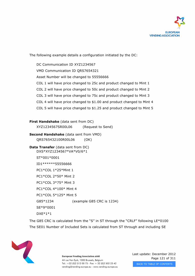
Last update: December 2012 Page 121 of 311
European Vending Association aisbl
44 rue Van Eyck, 1000 Brussels, Belgium Tel.: +32 (0)2 512 00 75 - Fax: + 32 (0)2 502 23 42 [email protected] - www.vending-europe.eu
The following example details a configuration initiated by the DC:
DC Communication ID XYZ1234567
VMD Communication ID QRS7654321
Asset Number will be changed to 55556666
COL 1 will have price changed to 25c and product changed to Mint 1
COL 2 will have price changed to 50c and product changed to Mint 2
COL 3 will have price changed to 75c and product changed to Mint 3
COL 4 will have price changed to $1.00 and product changed to Mint 4
COL 5 will have price changed to $1.25 and product changed to Mint 5
First Handshake (data sent from DC) XYZ1234567SR00L06 (Request to Send)
Second Handshake (data sent from VMD) QRS765432100R00L06 (OK)
Data Transfer (data sent from DC) DXS*XYZ1234567*VA*V0/6*1
ST*001*0001
ID1******55556666
PC1*COL 1*25*Mint 1
PC1*COL 2*50* Mint 2
PC1*COL 3*75* Mint 3
PC1*COL 4*100* Mint 4
PC1*COL 5*125* Mint 5
G85*1234 (example G85 CRC is 1234)
SE*9*0001
DXE*1*1
The G85 CRC is calculated from the “S” in ST through the “CRLF” following LE*0100
The SE01 Number of Included Sets is calculated from ST through and including SE
Last update: December 2012 Page 122 of 311
European Vending Association aisbl
44 rue Van Eyck, 1000 Brussels, Belgium Tel.: +32 (0)2 512 00 75 - Fax: + 32 (0)2 502 23 42 [email protected] - www.vending-europe.eu
4.8 APPLICABLE DEX/UCS DOCUMENTATION
The Uniform Code Council document "UCS for Direct Store Delivery Implementation Guide" provides a tremendous amount of information as to the operation of DEX/UCS. Although the entire document is very informative, more is provided than what is actually required for the vending industry. The following highlights the sections which are required for implementing this specification. Note the document is organized into two parts, the main chapters in the front and the appendices in the back.
UCS/DSD Implementation Guide Chapters
(Version 004010UCS)
III. THE UCS/DSD STANDARDS
DXS/DXE HEADER/TRAILER CONTROL SEGMENTS
DEX/UCS COMMUNICATIONS STANDARDS
Direct Connect Interface Standard
VI. MESSAGE FORMATS
INTRODUCTION
Transaction Set Syntax
Classification of Data Elements and Segments
Data Element Types
Data Element Length
DEX/UCS CONTROL SEGMENTS
Last update: December 2012 Page 123 of 311
European Vending Association aisbl
44 rue Van Eyck, 1000 Brussels, Belgium Tel.: +32 (0)2 512 00 75 - Fax: + 32 (0)2 502 23 42 [email protected] - www.vending-europe.eu
DXS – Application Header
DXE – Application Trailer
894 - DELIVERY/RETURN BASE RECORD
ST – Transaction Set Header
G85 – Record Integrity Check
SE – Transaction Set Trailer
VII. DIRECT CONNECT INTERFACE STANDARD
Appendix B – CRC GENERATION
Last update: December 2012 Page 124 of 311
European Vending Association aisbl
44 rue Van Eyck, 1000 Brussels, Belgium Tel.: +32 (0)2 512 00 75 - Fax: + 32 (0)2 502 23 42 [email protected] - www.vending-europe.eu
CHAPTER 5 - APPLICATION NOTES - DATA
5.1. APPLICATION NOTES FOR THE DATA
5.1.1. Data Element Configuration
This section explains a method by which part of the Vending Machine's electronics configuration may be reported or changed. The example chosen is a Freshbrew Coffee Machine and the Data Groups shown in the example are ID1 and IC1 for reporting and changing configuration respectively. Let us say that the Vending Machine is manufactured by the All Brewed Coffee Company (supplier ID code is ABC), and has serial number 9240571, and is an AB740 Machine Model with Build Standard 31. It is operated by the company Modern Vending Services (MVS) on site 19, which is located on route number 7, and has the MVS Machine Number 34. The Asset Number of the Vending Machine is defined by the operator MVS to be a 2 digit route number, followed by a 2 digit site number and ending with a 2 digit machine number for that site. MVS managers also prefix their Asset Numbers with the User Code MVS, so as to ensure that they always get good data. When first installed, the Vending Machine is able to report the manufacturer (ABC) programmed settings, which are contained in elements ID101, ID102 and ID103. These would be reported as follows within a longer stream of data from the machine : ID1 * ABC9240571 * AB740 * 31 cr lf If the installer only wanted to know the serial number, and was not interested in the model or build standard numbers, the report would be shorter : ID1 * ABC9240571 cr lf
Last update: December 2012 Page 125 of 311
European Vending Association aisbl
44 rue Van Eyck, 1000 Brussels, Belgium Tel.: +32 (0)2 512 00 75 - Fax: + 32 (0)2 502 23 42 [email protected] - www.vending-europe.eu
Note in both cases the unit serial number would normally be prefixed with the Manufacturer ID code from appendix B of this standard. If the Installer now wishes to set the Asset Number of the unit, they now enter the number using their portable Data Carrier, and the Data Carrier would send to the Vending Machine the following information together with any other configuration information that may be required : IC1 * ABC9240571 * * * * * MVS071934 cr lf This could be shortened still further, since the machine to be configured has already been confirmed in the ID1 field sent by the machine prior to the transmission of the IC1 data. In this case, the message would appear as : IC1 * * * * * MVS071934 cr lf The Vending Machine Serial Number cannot be reset by the Installer or the route person at any time. Thus if the message IC1 * MVS07 * * * * * MVS987654 cr lf were to be sent, the Vending Machine WOULD change the Asset Number, but WOULD NOT change the Serial Number. In this method, Service Record integrity may be preserved, since the user always knows that the data for the Vending Machine ABC9240571 always refers to the one physical unit, and is never duplicated or altered. Note that this example may also apply to the following units UNIT Reporting Changing Vending Machine (shown above) ID1 IC1 Coin Mechanism CA1 CC1 Vending Machine Controller CB1 BC1 Cashless 1 DA1 DC1 Cashless 2 DB1 DD1 Communication Gateway FA1 FC1 Audit Module AM1 AC1 Token Acceptor TA1 TC1 Every unit has a programmable asset number. It is mainly used for tracking purposes. It is separate from the serial number and field configurable. Some units offer a keyboard or download option to programm this asset number. However the operator needs one single asset number to identify a complete installation of a vending machine and its associated units (Coin Mechanism, Cashless Device, Controller Board, …). The
Last update: December 2012 Page 126 of 311
European Vending Association aisbl
44 rue Van Eyck, 1000 Brussels, Belgium Tel.: +32 (0)2 512 00 75 - Fax: + 32 (0)2 502 23 42 [email protected] - www.vending-europe.eu
Control Board Asset Number of a Vending Machine is only related to the Control Board itself. It is not a mandatory field. Therefore the Machine Asset Number is the reference for accounting purposes. It is the mandatory field ID106. The Report Data Processing Software of an Operator requires the Machine Asset Number. A Vending Machine must offer the possibility to set ID106 in the field. 5.1.2. Manual Data Entry
From time to time the operator will have to deal with machines which are not equipped with modern electronics and are unable to report, for example, the number of cups or cans sold. In this case, the Standard makes provision for the portable Data Carrier to store the manually entered Meter / Counter Readings in Data Groups MR1 and MR2. This requires the software of the Data Carrier - whose actual method of operation is outside the scope of this standard or application note - to be able to construct a Data Record as if it had come from an EVA_DTS compatible machine. This would require storage of the Machine Asset Number, in ID106, the relevant Meter Readings, and any other data that the operator may require. For example, if MidShires Vending Services have machine 123 which has sold a total of 4567 cups since it was installed, the message stream could be as small as : ID1 * * * * * * MVS123 cr lf MR1 * 4567 cr lf If output directly on a ticket printer, the above data would appear as : ID1 * * * * * * MVS123 MR1 * 4567 which although not the easiest thing to understand to an untrained person, will make sense once explained. Clearly, the use of reported meter readings cannot prevent inaccurate reporting of sales information, since the person has to visually read the meter in the machine, then enter the data into their portable Data Carrier, before it can be entered to and processed by the Computer system.
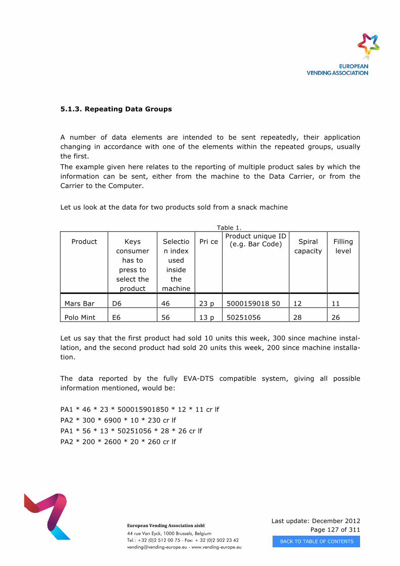
Last update: December 2012 Page 127 of 311
European Vending Association aisbl
44 rue Van Eyck, 1000 Brussels, Belgium Tel.: +32 (0)2 512 00 75 - Fax: + 32 (0)2 502 23 42 [email protected] - www.vending-europe.eu
5.1.3. Repeating Data Groups
A number of data elements are intended to be sent repeatedly, their application changing in accordance with one of the elements within the repeated groups, usually the first. The example given here relates to the reporting of multiple product sales by which the information can be sent, either from the machine to the Data Carrier, or from the Carrier to the Computer. Let us look at the data for two products sold from a snack machine
Table 1.
Product Keys consumer
has to press to
select the product
Selection index used inside the
machine
Pri ce Product unique ID (e.g. Bar Code) Spiral
capacity Filling level
Mars Bar D6 46 23 p 5000159018 50 12 11
Polo Mint E6 56 13 p 50251056 28 26 Let us say that the first product had sold 10 units this week, 300 since machine instal- lation, and the second product had sold 20 units this week, 200 since machine installa- tion. The data reported by the fully EVA-DTS compatible system, giving all possible information mentioned, would be: PA1 * 46 * 23 * 500015901850 * 12 * 11 cr lf PA2 * 300 * 6900 * 10 * 230 cr lf PA1 * 56 * 13 * 50251056 * 28 * 26 cr lf PA2 * 200 * 2600 * 20 * 260 cr lf
Last update: December 2012 Page 128 of 311
European Vending Association aisbl
44 rue Van Eyck, 1000 Brussels, Belgium Tel.: +32 (0)2 512 00 75 - Fax: + 32 (0)2 502 23 42 [email protected] - www.vending-europe.eu
If output directly on a ticket printer, the above data would appear as : PA1 * 46 * 23 * 500015901850 * 12 * 11 PA2 * 300 * 6900 * 10 * 230 PA1 * 56 * 13 * 50251056 * 28 * 26 PA2 * 200 * 2600 * 20 * 260
clearly showing that the PA2 group describing the product sales follows the PA1 group, identifying which product.
Other examples of repeating information may be found, for example: DA1-DA7 Debit Card transactions DA101 PA1 - PA5 Products Sold PA101 CA11 Coins Accepted CA1101 CA12 Coins Dispensed CA1201 CA13 Manually Filled Coin CA1301 CA14 Banknotes Accepted CA1401 TA7 Tokens Accepted TA701 TA8 Token Dispensed TA801 TA9 Tokens Filled TA901 LA1 PriceList LA101 EA1 Event Durations EA101 EA2 Event Occurences EA201 EA8 Repeating Events EA801 and so on.
5.1.4. Selective reporting and selective resetting of data elements
› 5.1.4.1. Using the command (CD) method
Typically all of the data elements are transferred from the vending machine device (VMD) to the data carrier (DC) but often is only a limited amount of data elements of interest for a specific operator/company. There is a provision in the Data Transfer Standard to transfer selected groups of data elements and thereby reduce the transmission time and the amount of data transmitted. Please be aware of that
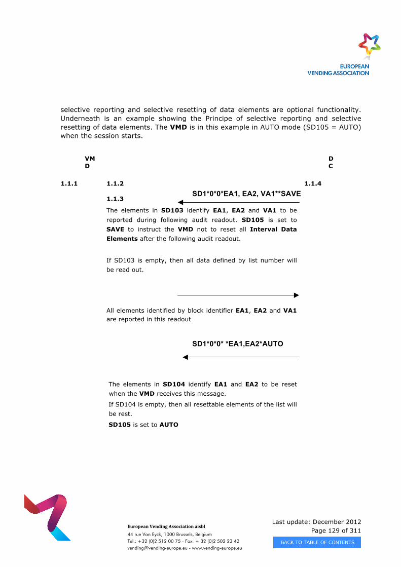
Last update: December 2012 Page 129 of 311
European Vending Association aisbl
44 rue Van Eyck, 1000 Brussels, Belgium Tel.: +32 (0)2 512 00 75 - Fax: + 32 (0)2 502 23 42 [email protected] - www.vending-europe.eu
selective reporting and selective resetting of data elements are optional functionality. Underneath is an example showing the Principe of selective reporting and selective resetting of data elements. The VMD is in this example in AUTO mode (SD105 = AUTO) when the session starts.
VMD
DC
1.1.1 1.1.2
1.1.3
The elements in SD103 identify EA1, EA2 and VA1 to be reported during following audit readout. SD105 is set to SAVE to instruct the VMD not to reset all Interval Data Elements after the following audit readout.
If SD103 is empty, then all data defined by list number will be read out.
1.1.4
All elements identified by block identifier EA1, EA2 and VA1 are reported in this readout
The elements in SD104 identify EA1 and EA2 to be reset when the VMD receives this message.
If SD104 is empty, then all resettable elements of the list will be rest.
SD105 is set to AUTO
SD1*0*0*EA1, EA2, VA1**SAVE
SD1*0*0* *EA1,EA2*AUTO
Last update: December 2012 Page 130 of 311
European Vending Association aisbl
44 rue Van Eyck, 1000 Brussels, Belgium Tel.: +32 (0)2 512 00 75 - Fax: + 32 (0)2 502 23 42 [email protected] - www.vending-europe.eu
› 5.1.4.2 Using the list method
Lists are defined in 3.6.1.2 READOUT OF DATA There are 2 different principles, the record mask principle and the SD1 principle, to decide which data are to be read out. THE SD1 PRINCIPLE This principle works in the way that a specification file in the form of SD1 is sent (write) before the readout of data. The field SD103 contains information about which data you wish to read out at the next readout (read); SD103 may contain either - one or more data block identifiers ( as PA1, EA1, etc ) or - record layout identifiers ( L101, L102 ) The elements composing the SD103 field are separated by commas. The field SD104 can contain information about specific resettable data that you wish to reset after the next readout. (in same format as SD103) The field SD105 can contain information about resetting of all resettable data after the next readout. The field SD105 can accept the following values: 1 means: Reset all data 0 means: Don't reset, reset only data specified within SD104 If the field is not sent, the data will not be reset. A record layout is a vendor specific layout of audit data, and is a specific list of audit data selected from the audit dictionary. L101 is the minimum EVA-DTS specified layout ( see 2.4 )
Last update: December 2012 Page 131 of 311
European Vending Association aisbl
44 rue Van Eyck, 1000 Brussels, Belgium Tel.: +32 (0)2 512 00 75 - Fax: + 32 (0)2 502 23 42 [email protected] - www.vending-europe.eu
Example 1: SD1*0*0*EA1,EA2,VA1*EA1,EA2CRLF Read out SD103:EA1, Reset SD104:EA1, EA2 EA2 (event/error after next readout (read) protocol) and VA1 (sales audit) at the next readout (read). Example 2: SD1*0*0*EA1,EA2,VA1**1CRLF Reset all resettable data after the next readout The element ID1 (Machine Identification) is always sent, also in spite of the block identifier having not been specified in SD103. Concerning ''Message Sequence'', please see the example ''AUDIT COLLECTION WITH CONFIGURATION BY SD1'' in update reference. THE LIST NUMBER PRINCIPLE If no SD103 specification (write) is sent, before a ''read command'' is given, all data will according to the ''list number specification'' be read out. If a list 1 is read out the resettable data will hereafter be reset. If list 2 is read out, no data will be reset. The list contents can change from vendor to vendor, but some type of data must be present from any EVA-DTS compliant device. ( set reference to minimum audit data list ). READ-IN OF DATA If you wish to configurate/program a vending machine (write), it is often so that the machine must not contain any audit. In other words, an audit readout with a subsequent reset of resettable digits must be carried through, before the machine can be configurated (write). Of course, you can send SD1 (write) even though there is audit in the vending machine.
Last update: December 2012 Page 132 of 311
European Vending Association aisbl
44 rue Van Eyck, 1000 Brussels, Belgium Tel.: +32 (0)2 512 00 75 - Fax: + 32 (0)2 502 23 42 [email protected] - www.vending-europe.eu
5.1.5. Element Length
A special note is brought to the attention of all users of this standard, concerning the length of various data elements currently implemented in some US equipment which are equipped to provide data prior to this standard being formally published.
As indicated, each of the Vending Data Transfer data elements has a defined minimum and maximum length which provides for variable length data. This is a provision of the DEX/UCS standards which the Vending Industry has adopted. The DEX/UCS standards further state that for numeric and decimal data elements, no leading zeros are permitted to be transmitted.
Initial production vending machine audit devices (VMADs), that use the Direct Connect Communications Protocol, transmit fixed length data elements of eight (8) characters
with leading zeros. These devices shall all be grandfathered and all portable data collection devices (PDCDs) should be capable of reading such data. All future VMAD
products should adhere to the variable length data standard with the “no leading zeros” specification.
Shown below are the data element numbers which are known to be affected:
VA101 VA102 VA103 VA104
Last update: December 2012 Page 133 of 311
European Vending Association aisbl
44 rue Van Eyck, 1000 Brussels, Belgium Tel.: +32 (0)2 512 00 75 - Fax: + 32 (0)2 502 23 42 [email protected] - www.vending-europe.eu
CA201 CA202 CA203 CA204
CA301 CA302 CA303 CA304 CA305 CA306 CA307 CA308
CA401 CA402 CA403 CA404
CA501 CA502
CA601
DA201 DA202 DA203 DA204
DA301 DA302
DA401 DA402
DA601 DA602
EA301
EA701 EA702
5.1.6 Data Element Format (Type)
It is often observed that developers process elements in various ways when it comes to the limit of the available digits specified (e.g. “Nc 01 08”). In some cases the specified max. element length is used up after a short period of two years or less. In order to set clear rules for back office developers the following behaviour must be implemented:
As soon as the maximum decimal value is reached measuring starts back at zero (e.g. after 99’999’999 continue with 0). It is not allowed to extend the element size even when the hexadecimal value would support it.
It is also possible for the machine to reach internal overflow conditions before the maximum specified element size has been reached. In this case, a reset of the value to 'O' will be based on binary numbers (byte, word and double word)
Back office developers can detect an overflow by cross checking resettable and cumulative values of the last read out period. After each overflow the offset value according the maximum element length must be added to the new cumulative value (e.g. 327+100’000’000).
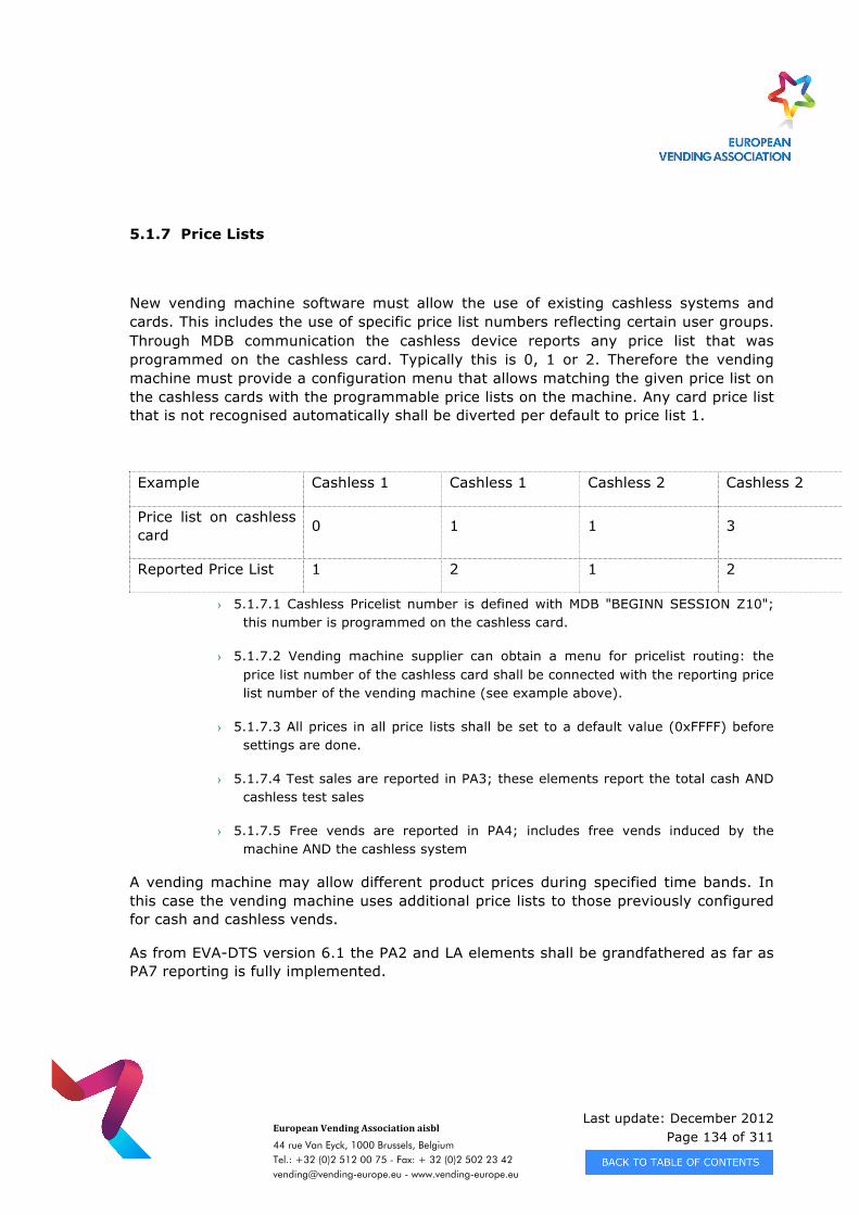
Last update: December 2012 Page 134 of 311
European Vending Association aisbl
44 rue Van Eyck, 1000 Brussels, Belgium Tel.: +32 (0)2 512 00 75 - Fax: + 32 (0)2 502 23 42 [email protected] - www.vending-europe.eu
5.1.7 Price Lists
New vending machine software must allow the use of existing cashless systems and cards. This includes the use of specific price list numbers reflecting certain user groups. Through MDB communication the cashless device reports any price list that was programmed on the cashless card. Typically this is 0, 1 or 2. Therefore the vending machine must provide a configuration menu that allows matching the given price list on the cashless cards with the programmable price lists on the machine. Any card price list that is not recognised automatically shall be diverted per default to price list 1.
Example Cashless 1 Cashless 1 Cashless 2 Cashless 2
Price list on cashless card 0 1 1 3
Reported Price List 1 2 1 2
› 5.1.7.1 Cashless Pricelist number is defined with MDB "BEGINN SESSION Z10"; this number is programmed on the cashless card.
› 5.1.7.2 Vending machine supplier can obtain a menu for pricelist routing: the price list number of the cashless card shall be connected with the reporting price list number of the vending machine (see example above).
› 5.1.7.3 All prices in all price lists shall be set to a default value (0xFFFF) before settings are done.
› 5.1.7.4 Test sales are reported in PA3; these elements report the total cash AND cashless test sales
› 5.1.7.5 Free vends are reported in PA4; includes free vends induced by the machine AND the cashless system
A vending machine may allow different product prices during specified time bands. In this case the vending machine uses additional price lists to those previously configured for cash and cashless vends.
As from EVA-DTS version 6.1 the PA2 and LA elements shall be grandfathered as far as PA7 reporting is fully implemented.
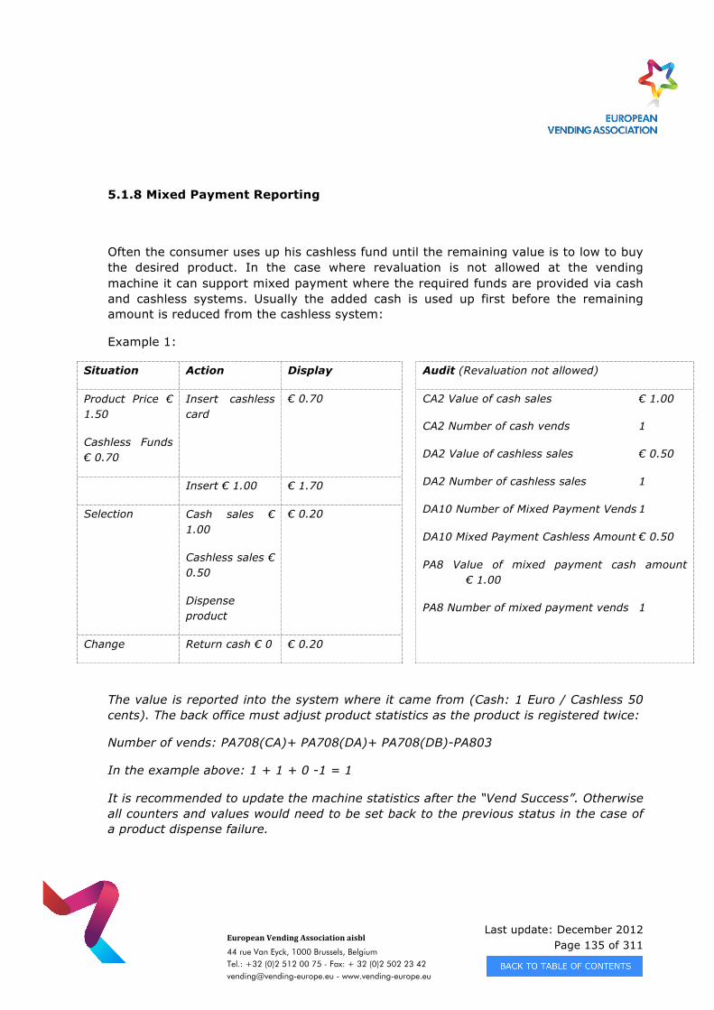
Last update: December 2012 Page 135 of 311
European Vending Association aisbl
44 rue Van Eyck, 1000 Brussels, Belgium Tel.: +32 (0)2 512 00 75 - Fax: + 32 (0)2 502 23 42 [email protected] - www.vending-europe.eu
5.1.8 Mixed Payment Reporting
Often the consumer uses up his cashless fund until the remaining value is to low to buy the desired product. In the case where revaluation is not allowed at the vending machine it can support mixed payment where the required funds are provided via cash and cashless systems. Usually the added cash is used up first before the remaining amount is reduced from the cashless system:
Example 1:
Situation Action Display Audit (Revaluation not allowed)
Product Price € 1.50
Cashless Funds € 0.70
Insert cashless card
€ 0.70 CA2 Value of cash sales € 1.00
CA2 Number of cash vends 1
DA2 Value of cashless sales € 0.50
DA2 Number of cashless sales 1
DA10 Number of Mixed Payment Vends 1
DA10 Mixed Payment Cashless Amount € 0.50
PA8 Value of mixed payment cash amount € 1.00
PA8 Number of mixed payment vends 1
Insert € 1.00 € 1.70
Selection Cash sales € 1.00
Cashless sales € 0.50
Dispense product
€ 0.20
Change Return cash € 0 € 0.20
The value is reported into the system where it came from (Cash: 1 Euro / Cashless 50 cents). The back office must adjust product statistics as the product is registered twice:
Number of vends: PA708(CA)+ PA708(DA)+ PA708(DB)-PA803
In the example above: 1 + 1 + 0 -1 = 1
It is recommended to update the machine statistics after the “Vend Success”. Otherwise all counters and values would need to be set back to the previous status in the case of a product dispense failure.
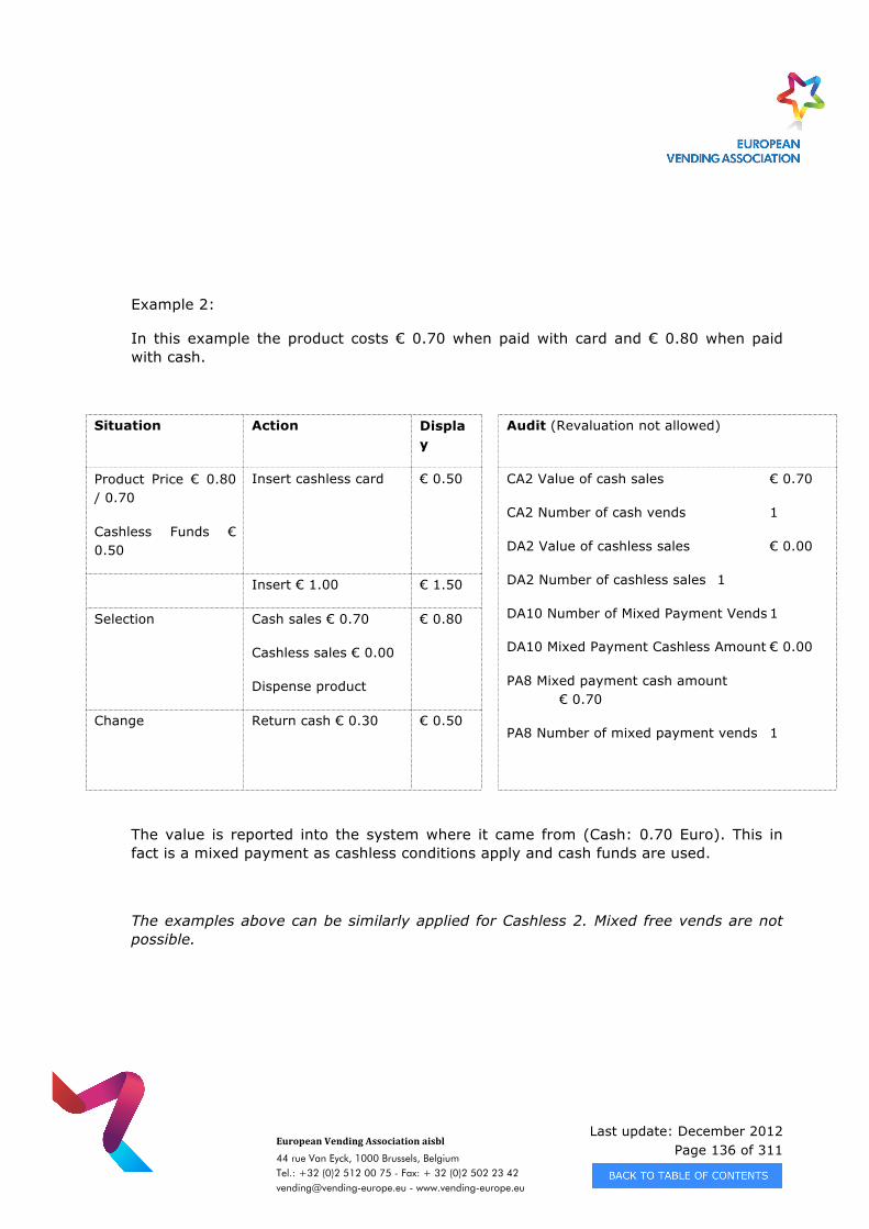
Last update: December 2012 Page 136 of 311
European Vending Association aisbl
44 rue Van Eyck, 1000 Brussels, Belgium Tel.: +32 (0)2 512 00 75 - Fax: + 32 (0)2 502 23 42 [email protected] - www.vending-europe.eu
Example 2:
In this example the product costs € 0.70 when paid with card and € 0.80 when paid with cash.
Situation Action Display
Audit (Revaluation not allowed)
Product Price € 0.80 / 0.70
Cashless Funds € 0.50
Insert cashless card € 0.50 CA2 Value of cash sales € 0.70
CA2 Number of cash vends 1
DA2 Value of cashless sales € 0.00
DA2 Number of cashless sales 1
DA10 Number of Mixed Payment Vends 1
DA10 Mixed Payment Cashless Amount € 0.00
PA8 Mixed payment cash amount € 0.70
PA8 Number of mixed payment vends 1
Insert € 1.00 € 1.50
Selection Cash sales € 0.70
Cashless sales € 0.00
Dispense product
€ 0.80
Change Return cash € 0.30 € 0.50
The value is reported into the system where it came from (Cash: 0.70 Euro). This in fact is a mixed payment as cashless conditions apply and cash funds are used.
The examples above can be similarly applied for Cashless 2. Mixed free vends are not possible.
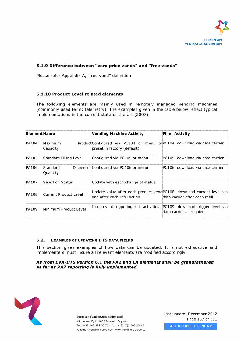
Last update: December 2012 Page 137 of 311
European Vending Association aisbl
44 rue Van Eyck, 1000 Brussels, Belgium Tel.: +32 (0)2 512 00 75 - Fax: + 32 (0)2 502 23 42 [email protected] - www.vending-europe.eu
5.1.9 Difference between “zero price vends” and “free vends”
Please refer Appendix A, “free vend” definition.
5.1.10 Product Level related elements
The following elements are mainly used in remotely managed vending machines (commonly used term: telemetry). The examples given in the table below reflect typical implementations in the current state-of-the-art (2007).
Element Name Vending Machine Activity Filler Activity
PA104 Maximum Product Capacity
Configured via PC104 or menu or preset in factory (default)
PC104, download via data carrier
PA105 Standard Filling Level Configured via PC105 or menu PC105, download via data carrier
PA106 Standard Dispensed Quantity
Configured via PC106 or menu PC106, download via data carrier
PA107 Selection Status Update with each change of status
PA108 Current Product Level Update value after each product vend and after each refill action
PC108, download current level via data carrier after each refill
PA109 Minimum Product Level Issue event triggering refill activities PC109, download trigger level via
data carrier as requied
5.2. EXAMPLES OF UPDATING DTS DATA FIELDS
This section gives examples of how data can be updated. It is not exhaustive and implementers must insure all relevant elements are modified accordingly. As from EVA-DTS version 6.1 the PA2 and LA elements shall be grandfathered as far as PA7 reporting is fully implemented.
Last update: December 2012 Page 138 of 311
European Vending Association aisbl
44 rue Van Eyck, 1000 Brussels, Belgium Tel.: +32 (0)2 512 00 75 - Fax: + 32 (0)2 502 23 42 [email protected] - www.vending-europe.eu
5.2.1 Continuous update
All EVA-DTS elements must be updated with current transaction values. The calculation of monetary totals by multiplying counters with prices may lead to incorrect audit data (example: a price change during the read-out period would lead to incorrect audit data) and is therefore not allowed. 5.2.2 Value Token reporting
Some manufacturers do report value token in CA3. This behaviour is not allowed. Value token are not cash. Tokens shall be reported separately in their dedicated blocks (TA). 5.2.3 Vend Examples
1. Field Used In Example 2. Cash Vend Example 3. Card Vend Example 4. Cash and Non-Revalue Card Vend Example 5. Card Vend (With Discount) Example 6. Card Vend (With Surcharge) Example 7. Vend Token Vend Example 8. Value Token Vend Example 9. Value Token Vend (With Overpay) Example
10. Cash vend Pre-Select (Cup discount) Example 11. Card vend Pre-Select (Cup discount) Example 12. Card vend Pre-Select (card discount) Example 13. Cash vend Pre-Select (surcharge) Example 14. Cash vend (prices lists) Example 15. Card vend (prices lists) Example 16. Value Token Vend (prices lists) Example
5.2.4. Cash Examples
1. Fields Used In Examples 2. Changer Manual Fill Tubes 3. Changer Manual Fill Cash 4. Changer Manual Dispensed 5. Insert Coin Into Cash-Box 6. Insert Coin Into Tubes
7. Escrow (Coins Dispensed) 8. Overpay 9. Card Revalue 10. Insert Banknote
Last update: December 2012 Page 139 of 311
European Vending Association aisbl
44 rue Van Eyck, 1000 Brussels, Belgium Tel.: +32 (0)2 512 00 75 - Fax: + 32 (0)2 502 23 42 [email protected] - www.vending-europe.eu
5.2.3. Vend Examples
These examples do not show all concerned data blocks within a vend session. They only describe the treatment of related data blocks under specific circumstances.
› 5.2.3.1 Fields Used In Examples
VA1, CA2, CA7, DA2, DA5, DA10, TA2, TA3, TA5, PA1, (PA2, LA1), PA7, PA8 VA1*0*0*0*0*0*0*0*0*0*0*0*0 VA101 value of all paid vend sales since initialization VA101= CA201 + DA201 + DB201 + TA201 + TA205 VA102 number of all paid vend sales since initialization VA103 value of all paid vend sales since last reset VA103= CA203 + DA203 + DB203 + TA203 + TA207 VA104 number of all paid vend sales since last reset VA105 value of all discounted paid vends since initialization VA106 number of all discounted paid vends since initialization VA107 value of all discounted paid vends since last reset VA108 number of all discounted paid vends since last reset VA109 value of all surcharged paid vends since initialization VA110 number of all surcharged paid vends since initialization VA111 value of all surcharged paid vends since last reset VA112 number of all surcharged paid vends since last reset CA2*0*0*0*0 CA201 Value of cash sales (coins+ banknotes) since initialization CA202 number of cash sales since initialization CA203 Value of cash sales since last reset CA204 number of cash sales since last reset DA2*0*0*0*0 DA201 Value of card sales since initialization DA202 number of card sales since initialization DA203 Value of card sales since last reset DA204 number of card sales since last reset DA5*0*0*0*0*0*0*0*0 DA501 Value of card discounts since last reset DA502 number of card discounts since last reset DA503 Value of card discounts since initialization DA504 number of card discounts since initialization
Last update: December 2012 Page 140 of 311
European Vending Association aisbl
44 rue Van Eyck, 1000 Brussels, Belgium Tel.: +32 (0)2 512 00 75 - Fax: + 32 (0)2 502 23 42 [email protected] - www.vending-europe.eu
DA505 Value of card surcharges since last reset DA506 number of card surcharges since last reset DA507 Value of card surcharges since initialization DA508 number of card surcharges since initialization DA10*0*0*0*0 DA1001 Cashless 1 Number of Mixed Payment Vends Since Initialization DA1002 Cashless 1 Value of Mixed Payment Cashless Amount Since Initialization DA1003 Cashless 1 Number of Mixed Payment Vends Since Last Reset DA1004 Cashless 1 Value of Mixed Payment Cashless Amount Since Last Reset TA2*0*0*0*0*0*0*0*0 TA201 Value of all vend token sales since initialization TA202 number of all vend token sales since initialization TA203 Value of all vend token sales since last reset TA204 number of all vend token sales since last reset TA205 Value of all value token sales since initialization TA206 number of all value token sales since initialization TA207 Value of all value token sales since last reset TA208 number of all value token sales since last reset TA5*0*0 TA501 Value of value token overpay received since last reset Insert money –change paid – vend price = overpay value TA502 Value of value token overpay received since initialization PA1*1*40*****0 PA101 Product number PA102 price of the product PA107 Selection status: 0 or blank = present 1 = not present PA2*0*0*0*0*0*0*0* (use PA7) PA201 number of paid products vended since initialization PA202 value of paid products vended since initialization PA203 number of paid products vended since last reset PA204 value of paid products vended since last reset PA205 number of discounted paid vends since initialization PA206 value of discounted paid vends since initialization PA207 number of discounted paid vends since last reset PA208 value of discounted paid vends since last reset PA209 number of surcharges paid since initialization PA210 value of surcharges paid since initialization
Last update: December 2012 Page 141 of 311
European Vending Association aisbl
44 rue Van Eyck, 1000 Brussels, Belgium Tel.: +32 (0)2 512 00 75 - Fax: + 32 (0)2 502 23 42 [email protected] - www.vending-europe.eu
PA211 number of surcharges paid since last reset PA212 value of surcharges paid since last reset LA1*0*0*0*0*0 (use PA7) LA101 price list number LA102 product number LA103 price LA104 number of vends since last reset LA105 number of vends since initialization PA7*0*0*0*0*0*0*0*0 PA701 Product Number PA702 Payment device PA703 Price list number PA704 Applied Price PA705 Number of sales Since Initialization PA706 Value of Sales Since Initialization PA707 Number of sales Since Last Reset PA708 Value of Sales Since Last Reset PA8*0*0*0*0 PA801 Number of Mixed Payment Vends Since Initialization PA802 Value of Mixed Payment Cash Amount Since Initialization PA803 Number of Mixed Payment Vends Since Last Reset PA804 Value of Mixed Payment Cash Amount Since Last Reset

Last update: December 2012 Page 142 of 311
European Vending Association aisbl
44 rue Van Eyck, 1000 Brussels, Belgium Tel.: +32 (0)2 512 00 75 - Fax: + 32 (0)2 502 23 42 [email protected] - www.vending-europe.eu
› 5.2.3.2 Cash Vend Example
User makes selection line = 6 price=0.40 VA1 VA101 value = value + 40 (PA1*6*40) VA102 number = number +1 VA103 value = value + 40 (PA1*6*40) VA104 number = number +1 CA2 CA201 value = value + 40 (PA1*6*40) CA202 number = number +1 CA203 value = value + 40 (PA1*6*40) CA204 number = number +1 Line 6 PA1 PA101 = 6 (product number) PA102 = 40 (price) PA107 = 0 (present) PA2 (use PA7) PA201 number = number +1 PA202 value = value + 40 (PA1*6*40) PA203 number = number +1 PA204 value = value + 40 (PA1*6*40) PA7 PA701 = 6 (product number) PA702 = CA (payment device) PA704 = 40 (price) PA705 number = number +1 PA706 value = value + 40 PA707 number = number +1 PA708 value = value + 40
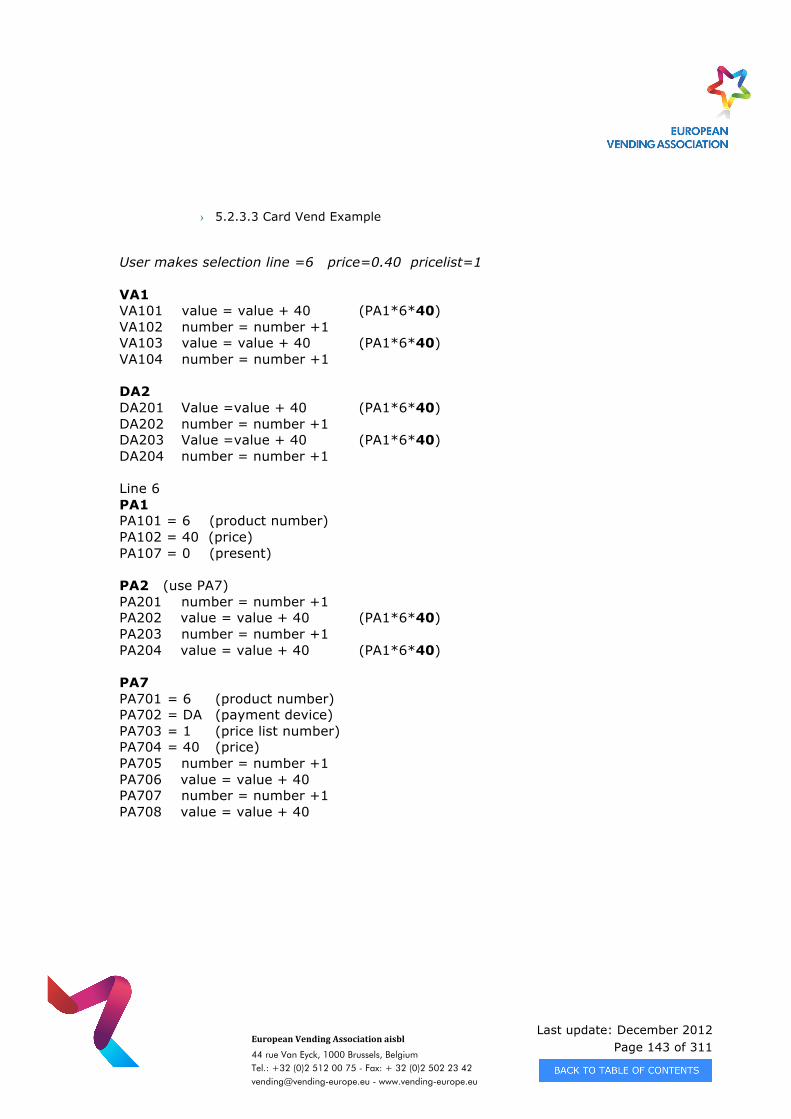
Last update: December 2012 Page 143 of 311
European Vending Association aisbl
44 rue Van Eyck, 1000 Brussels, Belgium Tel.: +32 (0)2 512 00 75 - Fax: + 32 (0)2 502 23 42 [email protected] - www.vending-europe.eu
› 5.2.3.3 Card Vend Example
User makes selection line =6 price=0.40 pricelist=1 VA1 VA101 value = value + 40 (PA1*6*40) VA102 number = number +1 VA103 value = value + 40 (PA1*6*40) VA104 number = number +1 DA2 DA201 Value =value + 40 (PA1*6*40) DA202 number = number +1 DA203 Value =value + 40 (PA1*6*40) DA204 number = number +1 Line 6 PA1 PA101 = 6 (product number) PA102 = 40 (price) PA107 = 0 (present) PA2 (use PA7) PA201 number = number +1 PA202 value = value + 40 (PA1*6*40) PA203 number = number +1 PA204 value = value + 40 (PA1*6*40) PA7 PA701 = 6 (product number) PA702 = DA (payment device) PA703 = 1 (price list number) PA704 = 40 (price) PA705 number = number +1 PA706 value = value + 40 PA707 number = number +1 PA708 value = value + 40
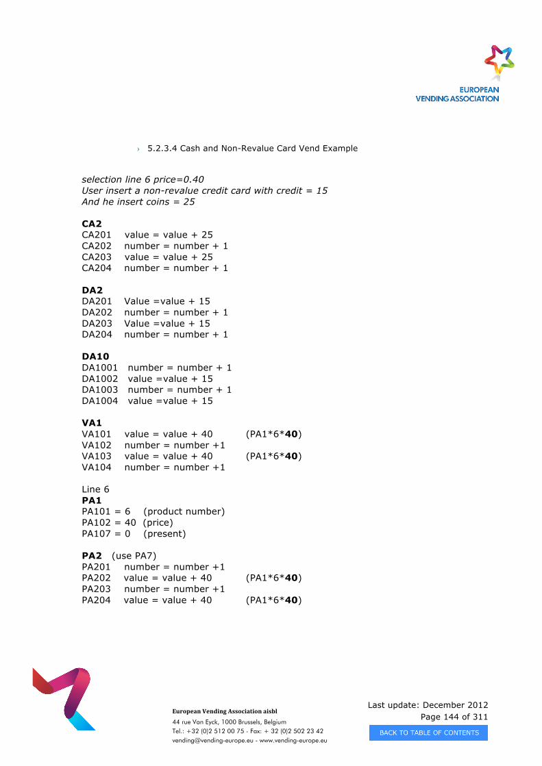
Last update: December 2012 Page 144 of 311
European Vending Association aisbl
44 rue Van Eyck, 1000 Brussels, Belgium Tel.: +32 (0)2 512 00 75 - Fax: + 32 (0)2 502 23 42 [email protected] - www.vending-europe.eu
› 5.2.3.4 Cash and Non-Revalue Card Vend Example
selection line 6 price=0.40 User insert a non-revalue credit card with credit = 15 And he insert coins = 25 CA2 CA201 value = value + 25 CA202 number = number + 1 CA203 value = value + 25 CA204 number = number + 1 DA2 DA201 Value =value + 15 DA202 number = number + 1 DA203 Value =value + 15 DA204 number = number + 1 DA10 DA1001 number = number + 1 DA1002 value =value + 15 DA1003 number = number + 1 DA1004 value =value + 15 VA1 VA101 value = value + 40 (PA1*6*40) VA102 number = number +1 VA103 value = value + 40 (PA1*6*40) VA104 number = number +1 Line 6 PA1 PA101 = 6 (product number) PA102 = 40 (price) PA107 = 0 (present) PA2 (use PA7) PA201 number = number +1 PA202 value = value + 40 (PA1*6*40) PA203 number = number +1 PA204 value = value + 40 (PA1*6*40)
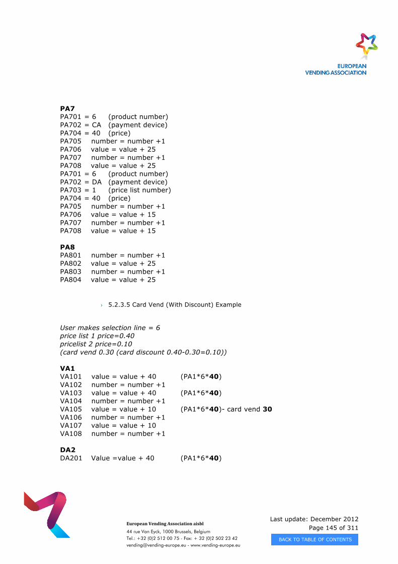
Last update: December 2012 Page 145 of 311
European Vending Association aisbl
44 rue Van Eyck, 1000 Brussels, Belgium Tel.: +32 (0)2 512 00 75 - Fax: + 32 (0)2 502 23 42 [email protected] - www.vending-europe.eu
PA7 PA701 = 6 (product number) PA702 = CA (payment device) PA704 = 40 (price) PA705 number = number +1 PA706 value = value + 25 PA707 number = number +1 PA708 value = value + 25 PA701 = 6 (product number) PA702 = DA (payment device) PA703 = 1 (price list number) PA704 = 40 (price) PA705 number = number +1 PA706 value = value + 15 PA707 number = number +1 PA708 value = value + 15 PA8 PA801 number = number +1 PA802 value = value + 25 PA803 number = number +1 PA804 value = value + 25
› 5.2.3.5 Card Vend (With Discount) Example
User makes selection line = 6 price list 1 price=0.40 pricelist 2 price=0.10 (card vend 0.30 (card discount 0.40-0.30=0.10)) VA1 VA101 value = value + 40 (PA1*6*40) VA102 number = number +1 VA103 value = value + 40 (PA1*6*40) VA104 number = number +1 VA105 value = value + 10 (PA1*6*40)- card vend 30 VA106 number = number +1 VA107 value = value + 10 VA108 number = number +1 DA2 DA201 Value =value + 40 (PA1*6*40)
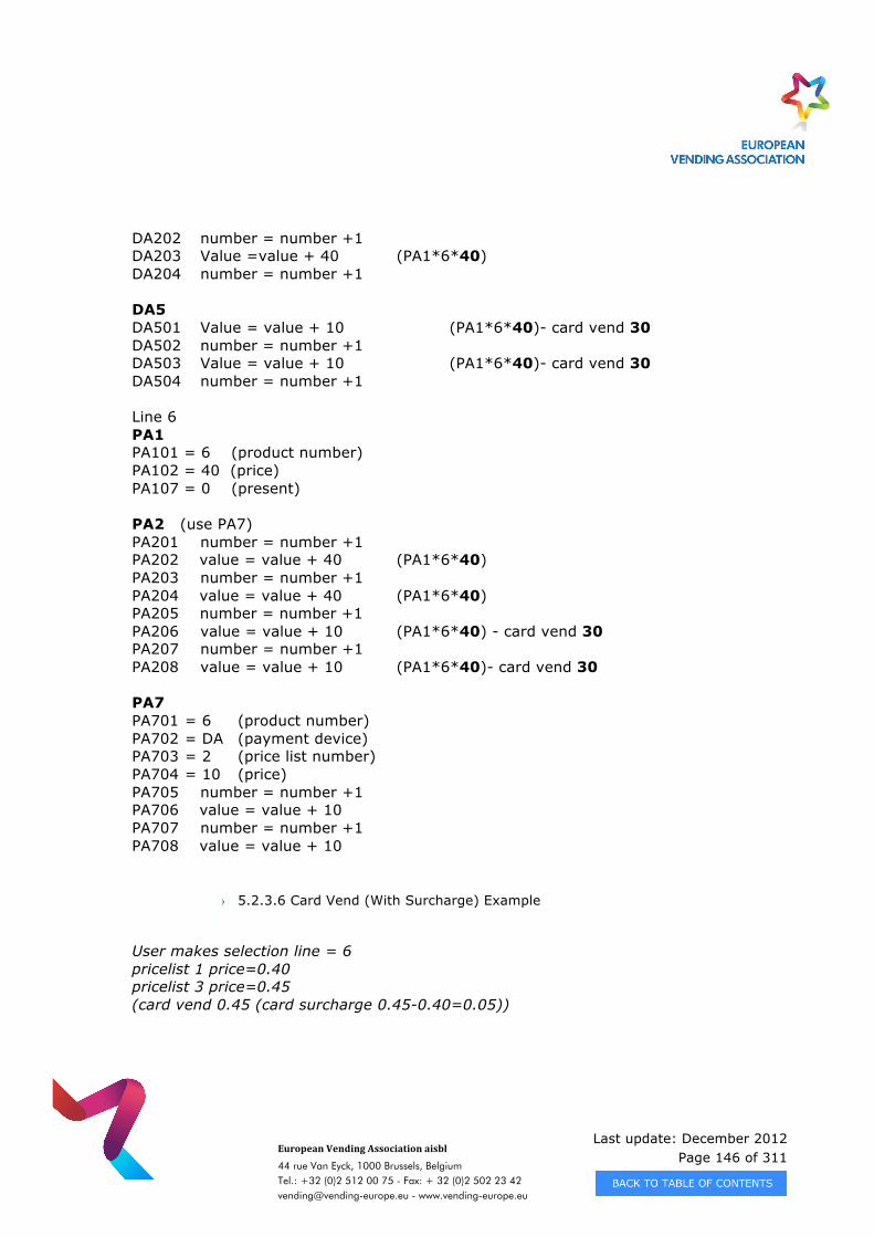
Last update: December 2012 Page 146 of 311
European Vending Association aisbl
44 rue Van Eyck, 1000 Brussels, Belgium Tel.: +32 (0)2 512 00 75 - Fax: + 32 (0)2 502 23 42 [email protected] - www.vending-europe.eu
DA202 number = number +1 DA203 Value =value + 40 (PA1*6*40) DA204 number = number +1 DA5 DA501 Value = value + 10 (PA1*6*40)- card vend 30 DA502 number = number +1 DA503 Value = value + 10 (PA1*6*40)- card vend 30 DA504 number = number +1 Line 6 PA1 PA101 = 6 (product number) PA102 = 40 (price) PA107 = 0 (present) PA2 (use PA7) PA201 number = number +1 PA202 value = value + 40 (PA1*6*40) PA203 number = number +1 PA204 value = value + 40 (PA1*6*40) PA205 number = number +1 PA206 value = value + 10 (PA1*6*40) - card vend 30 PA207 number = number +1 PA208 value = value + 10 (PA1*6*40)- card vend 30 PA7 PA701 = 6 (product number) PA702 = DA (payment device) PA703 = 2 (price list number) PA704 = 10 (price) PA705 number = number +1 PA706 value = value + 10 PA707 number = number +1 PA708 value = value + 10
› 5.2.3.6 Card Vend (With Surcharge) Example
User makes selection line = 6 pricelist 1 price=0.40 pricelist 3 price=0.45 (card vend 0.45 (card surcharge 0.45-0.40=0.05))
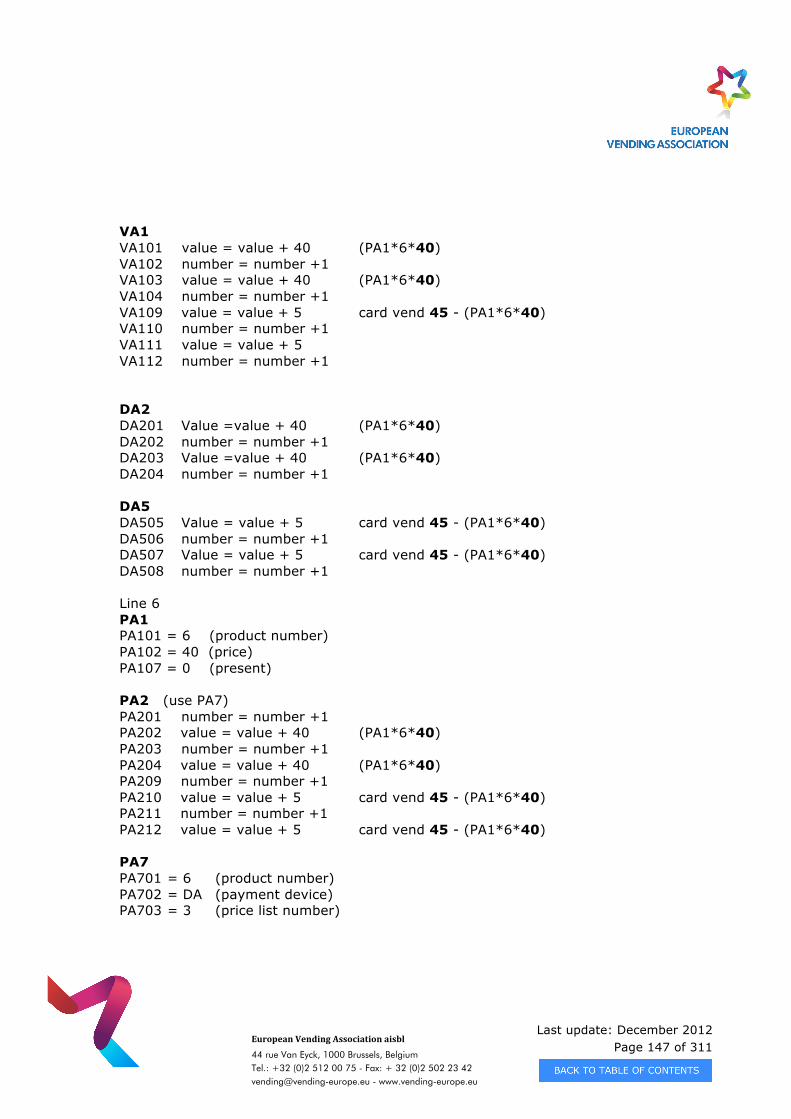
Last update: December 2012 Page 147 of 311
European Vending Association aisbl
44 rue Van Eyck, 1000 Brussels, Belgium Tel.: +32 (0)2 512 00 75 - Fax: + 32 (0)2 502 23 42 [email protected] - www.vending-europe.eu
VA1 VA101 value = value + 40 (PA1*6*40) VA102 number = number +1 VA103 value = value + 40 (PA1*6*40) VA104 number = number +1 VA109 value = value + 5 card vend 45 - (PA1*6*40) VA110 number = number +1 VA111 value = value + 5 VA112 number = number +1 DA2 DA201 Value =value + 40 (PA1*6*40) DA202 number = number +1 DA203 Value =value + 40 (PA1*6*40) DA204 number = number +1 DA5 DA505 Value = value + 5 card vend 45 - (PA1*6*40) DA506 number = number +1 DA507 Value = value + 5 card vend 45 - (PA1*6*40) DA508 number = number +1 Line 6 PA1 PA101 = 6 (product number) PA102 = 40 (price) PA107 = 0 (present) PA2 (use PA7) PA201 number = number +1 PA202 value = value + 40 (PA1*6*40) PA203 number = number +1 PA204 value = value + 40 (PA1*6*40) PA209 number = number +1 PA210 value = value + 5 card vend 45 - (PA1*6*40) PA211 number = number +1 PA212 value = value + 5 card vend 45 - (PA1*6*40) PA7 PA701 = 6 (product number) PA702 = DA (payment device) PA703 = 3 (price list number)
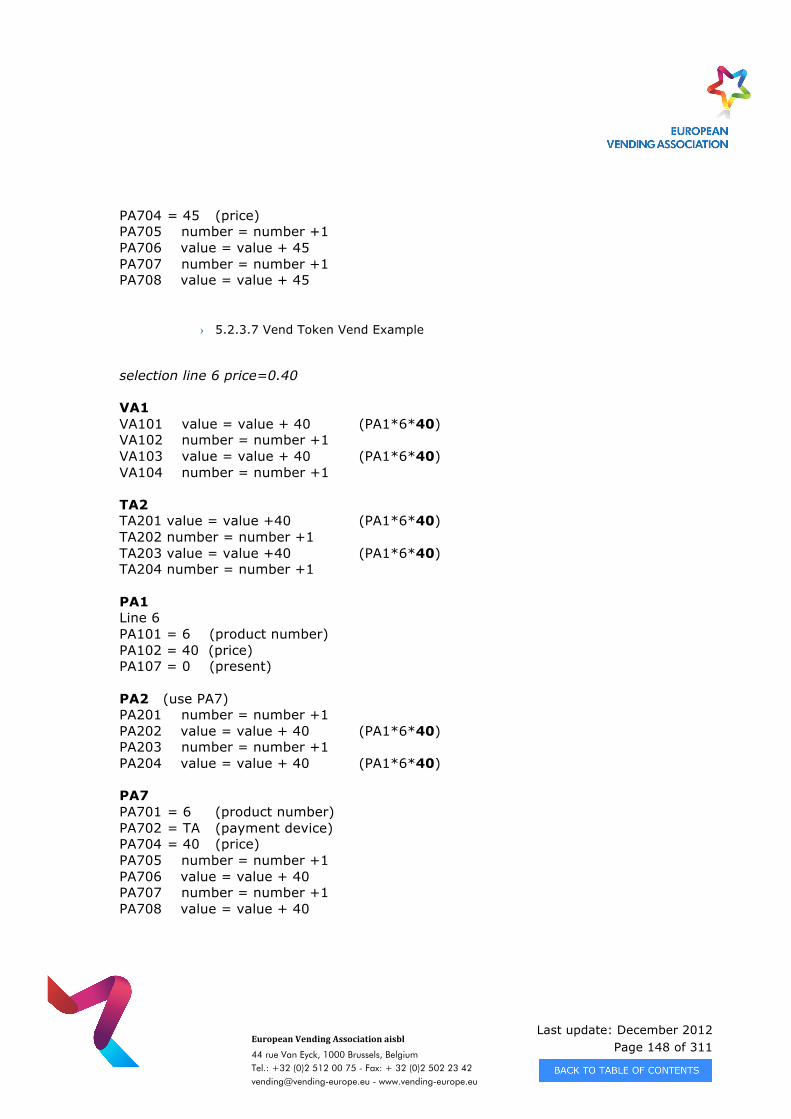
Last update: December 2012 Page 148 of 311
European Vending Association aisbl
44 rue Van Eyck, 1000 Brussels, Belgium Tel.: +32 (0)2 512 00 75 - Fax: + 32 (0)2 502 23 42 [email protected] - www.vending-europe.eu
PA704 = 45 (price) PA705 number = number +1 PA706 value = value + 45 PA707 number = number +1 PA708 value = value + 45
› 5.2.3.7 Vend Token Vend Example
selection line 6 price=0.40 VA1 VA101 value = value + 40 (PA1*6*40) VA102 number = number +1 VA103 value = value + 40 (PA1*6*40) VA104 number = number +1 TA2 TA201 value = value +40 (PA1*6*40) TA202 number = number +1 TA203 value = value +40 (PA1*6*40) TA204 number = number +1 PA1 Line 6 PA101 = 6 (product number) PA102 = 40 (price) PA107 = 0 (present) PA2 (use PA7) PA201 number = number +1 PA202 value = value + 40 (PA1*6*40) PA203 number = number +1 PA204 value = value + 40 (PA1*6*40) PA7 PA701 = 6 (product number) PA702 = TA (payment device) PA704 = 40 (price) PA705 number = number +1 PA706 value = value + 40 PA707 number = number +1 PA708 value = value + 40

Last update: December 2012 Page 149 of 311
European Vending Association aisbl
44 rue Van Eyck, 1000 Brussels, Belgium Tel.: +32 (0)2 512 00 75 - Fax: + 32 (0)2 502 23 42 [email protected] - www.vending-europe.eu
› 5.2.3.8 Value Token Vend Example
selection line 6 price=0.40 Value Token=0.40 VA1 VA101 value = value + 40 (PA1*6*40) VA102 number = number +1 VA103 value = value + 40 (PA1*6*40) VA104 number = number +1 TA2 TA205 value = value + 40 (PA1*6*40) TA206 number = number + 1 TA207 value = value + 40 (PA1*6*40) TA208 number = number + 1 PA1 Line 6 PA101 = 6 (product number) PA102 = 40 (price) PA107 = 0 (present) PA2 (use PA7) PA201 number = number +1 PA202 value = value + 40 (PA1*6*40) PA203 number = number +1 PA204 value = value + 40 (PA1*6*40) PA7 PA701 = 6 (product number) PA702 = TA (payment device) PA704 = 40 (price) PA705 number = number +1 PA706 value = value + 40 PA707 number = number +1 PA708 value = value + 40
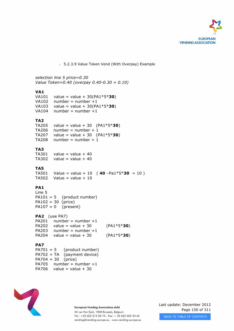
Last update: December 2012 Page 150 of 311
European Vending Association aisbl
44 rue Van Eyck, 1000 Brussels, Belgium Tel.: +32 (0)2 512 00 75 - Fax: + 32 (0)2 502 23 42 [email protected] - www.vending-europe.eu
› 5.2.3.9 Value Token Vend (With Overpay) Example
selection line 5 price=0.30 Value Token=0.40 (overpay 0.40-0.30 = 0.10) VA1 VA101 value = value + 30 (PA1*5*30) VA102 number = number +1 VA103 value = value + 30 (PA1*5*30) VA104 number = number +1 TA2 TA205 value = value + 30 (PA1*5*30) TA206 number = number + 1 TA207 value = value + 30 (PA1*5*30) TA208 number = number + 1 TA3 TA301 value = value + 40 TA302 value = value + 40 TA5 TA501 Value = value + 10 ( 40 –Pa1*5*30 = 10 ) TA502 Value = value + 10 PA1 Line 5 PA101 = 5 (product number) PA102 = 30 (price) PA107 = 0 (present) PA2 (use PA7) PA201 number = number +1 PA202 value = value + 30 (PA1*5*30) PA203 number = number +1 PA204 value = value + 30 (PA1*5*30) PA7 PA701 = 5 (product number) PA702 = TA (payment device) PA704 = 30 (price) PA705 number = number +1 PA706 value = value + 30
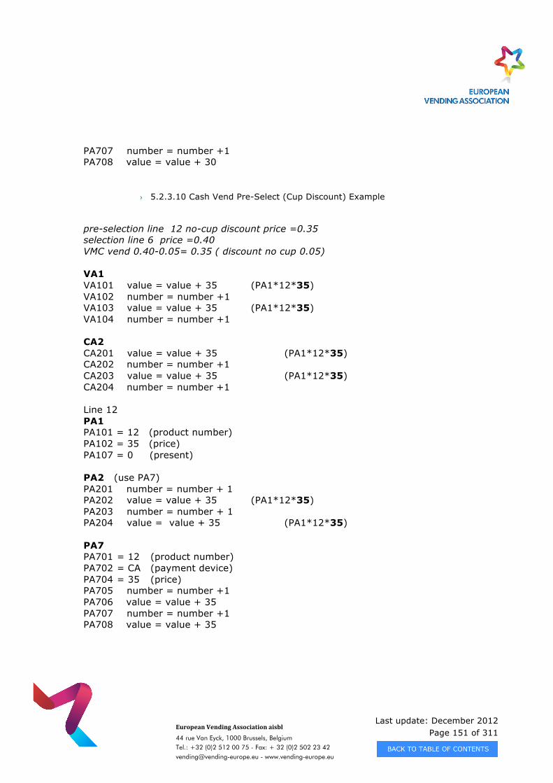
Last update: December 2012 Page 151 of 311
European Vending Association aisbl
44 rue Van Eyck, 1000 Brussels, Belgium Tel.: +32 (0)2 512 00 75 - Fax: + 32 (0)2 502 23 42 [email protected] - www.vending-europe.eu
PA707 number = number +1 PA708 value = value + 30
› 5.2.3.10 Cash Vend Pre-Select (Cup Discount) Example
pre-selection line 12 no-cup discount price =0.35 selection line 6 price =0.40 VMC vend 0.40-0.05= 0.35 ( discount no cup 0.05) VA1 VA101 value = value + 35 (PA1*12*35) VA102 number = number +1 VA103 value = value + 35 (PA1*12*35) VA104 number = number +1 CA2 CA201 value = value + 35 (PA1*12*35) CA202 number = number +1 CA203 value = value + 35 (PA1*12*35) CA204 number = number +1 Line 12 PA1 PA101 = 12 (product number) PA102 = 35 (price) PA107 = 0 (present) PA2 (use PA7) PA201 number = number + 1 PA202 value = value + 35 (PA1*12*35) PA203 number = number + 1 PA204 value = value + 35 (PA1*12*35) PA7 PA701 = 12 (product number) PA702 = CA (payment device) PA704 = 35 (price) PA705 number = number +1 PA706 value = value + 35 PA707 number = number +1 PA708 value = value + 35
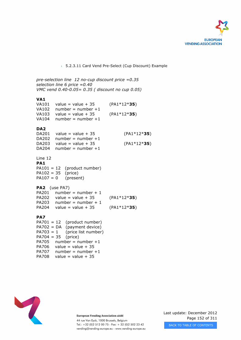
Last update: December 2012 Page 152 of 311
European Vending Association aisbl
44 rue Van Eyck, 1000 Brussels, Belgium Tel.: +32 (0)2 512 00 75 - Fax: + 32 (0)2 502 23 42 [email protected] - www.vending-europe.eu
› 5.2.3.11 Card Vend Pre-Select (Cup Discount) Example
pre-selection line 12 no-cup discount price =0.35 selection line 6 price =0.40 VMC vend 0.40-0.05= 0.35 ( discount no cup 0.05) VA1 VA101 value = value + 35 (PA1*12*35) VA102 number = number +1 VA103 value = value + 35 (PA1*12*35) VA104 number = number +1 DA2 DA201 value = value + 35 (PA1*12*35) DA202 number = number +1 DA203 value = value + 35 (PA1*12*35) DA204 number = number +1 Line 12 PA1 PA101 = 12 (product number) PA102 = 35 (price) PA107 = 0 (present) PA2 (use PA7) PA201 number = number + 1 PA202 value = value + 35 (PA1*12*35) PA203 number = number + 1 PA204 value = value + 35 (PA1*12*35) PA7 PA701 = 12 (product number) PA702 = DA (payment device) PA703 = 1 (price list number) PA704 = 35 (price) PA705 number = number +1 PA706 value = value + 35 PA707 number = number +1 PA708 value = value + 35
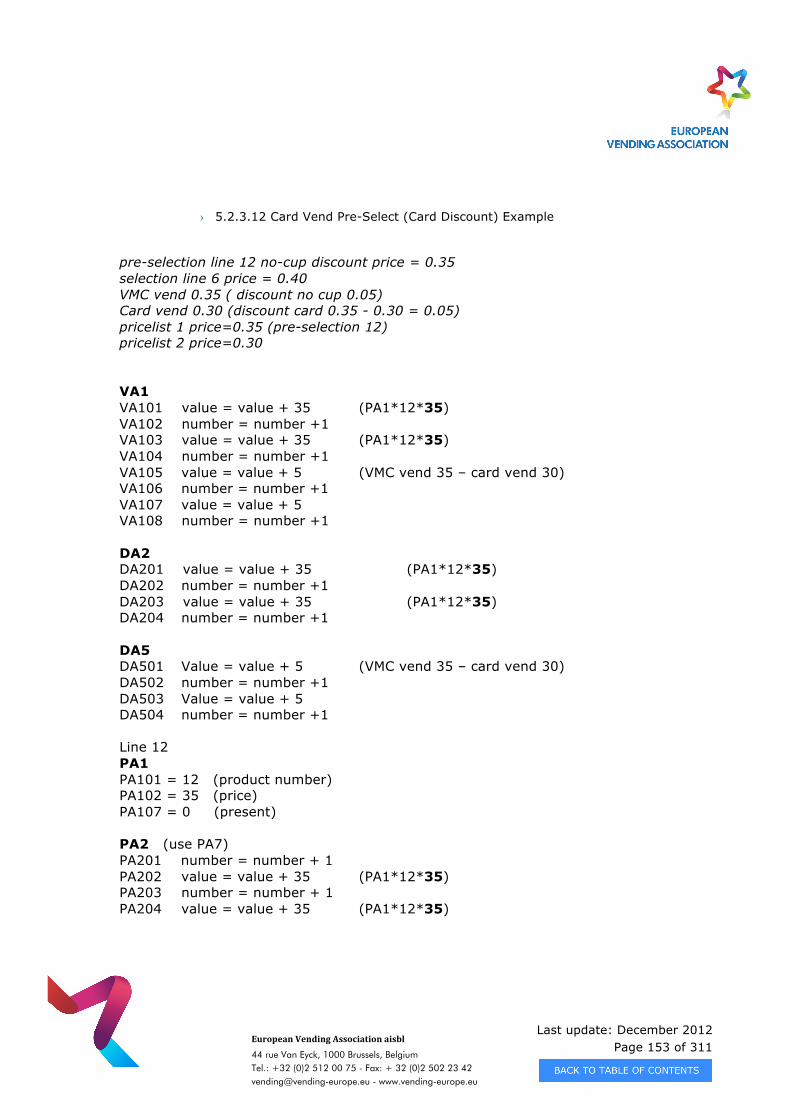
Last update: December 2012 Page 153 of 311
European Vending Association aisbl
44 rue Van Eyck, 1000 Brussels, Belgium Tel.: +32 (0)2 512 00 75 - Fax: + 32 (0)2 502 23 42 [email protected] - www.vending-europe.eu
› 5.2.3.12 Card Vend Pre-Select (Card Discount) Example
pre-selection line 12 no-cup discount price = 0.35 selection line 6 price = 0.40 VMC vend 0.35 ( discount no cup 0.05) Card vend 0.30 (discount card 0.35 - 0.30 = 0.05) pricelist 1 price=0.35 (pre-selection 12) pricelist 2 price=0.30 VA1 VA101 value = value + 35 (PA1*12*35) VA102 number = number +1 VA103 value = value + 35 (PA1*12*35) VA104 number = number +1 VA105 value = value + 5 (VMC vend 35 – card vend 30) VA106 number = number +1 VA107 value = value + 5 VA108 number = number +1 DA2 DA201 value = value + 35 (PA1*12*35) DA202 number = number +1 DA203 value = value + 35 (PA1*12*35) DA204 number = number +1 DA5 DA501 Value = value + 5 (VMC vend 35 – card vend 30) DA502 number = number +1 DA503 Value = value + 5 DA504 number = number +1 Line 12 PA1 PA101 = 12 (product number) PA102 = 35 (price) PA107 = 0 (present) PA2 (use PA7) PA201 number = number + 1 PA202 value = value + 35 (PA1*12*35) PA203 number = number + 1 PA204 value = value + 35 (PA1*12*35)
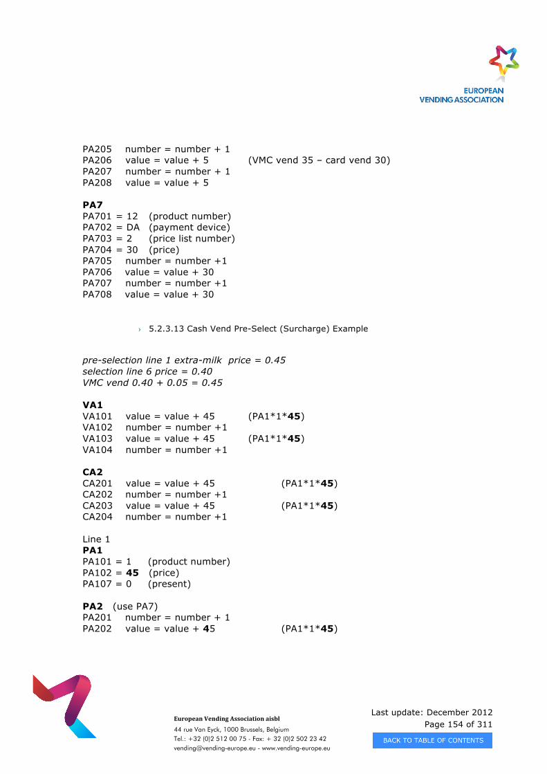
Last update: December 2012 Page 154 of 311
European Vending Association aisbl
44 rue Van Eyck, 1000 Brussels, Belgium Tel.: +32 (0)2 512 00 75 - Fax: + 32 (0)2 502 23 42 [email protected] - www.vending-europe.eu
PA205 number = number + 1 PA206 value = value + 5 (VMC vend 35 – card vend 30) PA207 number = number + 1 PA208 value = value + 5 PA7 PA701 = 12 (product number) PA702 = DA (payment device) PA703 = 2 (price list number) PA704 = 30 (price) PA705 number = number +1 PA706 value = value + 30 PA707 number = number +1 PA708 value = value + 30
› 5.2.3.13 Cash Vend Pre-Select (Surcharge) Example
pre-selection line 1 extra-milk price = 0.45 selection line 6 price = 0.40 VMC vend 0.40 + 0.05 = 0.45 VA1 VA101 value = value + 45 (PA1*1*45) VA102 number = number +1 VA103 value = value + 45 (PA1*1*45) VA104 number = number +1 CA2 CA201 value = value + 45 (PA1*1*45) CA202 number = number +1 CA203 value = value + 45 (PA1*1*45) CA204 number = number +1 Line 1 PA1 PA101 = 1 (product number) PA102 = 45 (price) PA107 = 0 (present) PA2 (use PA7) PA201 number = number + 1 PA202 value = value + 45 (PA1*1*45)
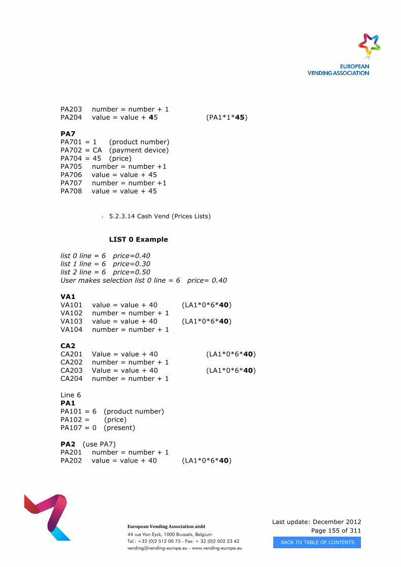
Last update: December 2012 Page 155 of 311
European Vending Association aisbl
44 rue Van Eyck, 1000 Brussels, Belgium Tel.: +32 (0)2 512 00 75 - Fax: + 32 (0)2 502 23 42 [email protected] - www.vending-europe.eu
PA203 number = number + 1 PA204 value = value + 45 (PA1*1*45) PA7 PA701 = 1 (product number) PA702 = CA (payment device) PA704 = 45 (price) PA705 number = number +1 PA706 value = value + 45 PA707 number = number +1 PA708 value = value + 45
› 5.2.3.14 Cash Vend (Prices Lists)
LIST 0 Example
list 0 line = 6 price=0.40 list 1 line = 6 price=0.30 list 2 line = 6 price=0.50 User makes selection list 0 line = 6 price= 0.40 VA1 VA101 value = value + 40 (LA1*0*6*40) VA102 number = number + 1 VA103 value = value + 40 (LA1*0*6*40) VA104 number = number + 1 CA2 CA201 Value = value + 40 (LA1*0*6*40) CA202 number = number + 1 CA203 Value = value + 40 (LA1*0*6*40) CA204 number = number + 1 Line 6 PA1 PA101 = 6 (product number) PA102 = (price) PA107 = 0 (present) PA2 (use PA7) PA201 number = number + 1 PA202 value = value + 40 (LA1*0*6*40)
Last update: December 2012 Page 156 of 311
European Vending Association aisbl
44 rue Van Eyck, 1000 Brussels, Belgium Tel.: +32 (0)2 512 00 75 - Fax: + 32 (0)2 502 23 42 [email protected] - www.vending-europe.eu
PA203 number = number + 1 PA204 value = value + 40 (LA1*0*6*40) LA1 (use PA7) LA101 = 0 LA102 = 6 LA103 = 40 LA104 number = number +1 LA105 number = number +1 PA7 PA701 = 6 (product number) PA702 = CA (payment device) PA703 = 0 (price list number) PA704 = 40 (price) PA705 number = number +1 PA706 value = value + 40 PA707 number = number +1 PA708 value = value + 40
› 5.2.3.14 Cash Vend LIST 1 Example
list 0 line = 6 price=0.40 list 1 line = 6 price=0.30 list 2 line = 6 price=0.50 User makes selection list 1 line = 6 price = 0.30 VA1 VA101 value = value + 30 (LA1*1*6*30) VA102 number = number +1 VA103 value = value + 30 (LA1*1*6*30) VA104 number = number +1 CA2 CA201 Value =value + 30 (LA1*1*6*30) CA202 number = number + 1 CA203 Value =value + 30 (LA1*1*6*30) CA204 number = number + 1 Line 6 PA1 PA101 = 6 (product number)
Last update: December 2012 Page 157 of 311
European Vending Association aisbl
44 rue Van Eyck, 1000 Brussels, Belgium Tel.: +32 (0)2 512 00 75 - Fax: + 32 (0)2 502 23 42 [email protected] - www.vending-europe.eu
PA102 = (price) PA107 = 0 (present) PA2 (use PA7) PA201 number = number + 1 PA202 value = value + 30 (LA1*1*6*30) PA203 number = number + 1 PA204 value = value + 30 (LA1*1*6*30) LA1 (use PA7) LA101 = 1 LA102 = 6 LA103 = 30 LA104 number = number + 1 LA105 number = number + 1
PA7 PA701 = 6 (product number) PA702 = CA (payment device) PA703 = 1 (price list number) PA704 = 30 (price) PA705 number = number +1 PA706 value = value + 30 PA707 number = number +1 PA708 value = value + 30
Cash Vend LIST 2 Example
list 0 line = 6 price=0.40 list 1 line = 6 price=0.30 list 2 line = 6 price=0.50 User makes selection list 2 line = 6 price = 0.50 VA1 VA101 value = value + 50 (LA1*2*6*50) VA102 number = number + 1 VA103 value = value + 50 ((LA1*2*6*50) VA104 number = number + 1 CA2 CA201 Value =value + 50 (LA1*2*6*50) CA202 number = number + 1 CA203 Value =value + 50 (LA1*2*6*50)
Last update: December 2012 Page 158 of 311
European Vending Association aisbl
44 rue Van Eyck, 1000 Brussels, Belgium Tel.: +32 (0)2 512 00 75 - Fax: + 32 (0)2 502 23 42 [email protected] - www.vending-europe.eu
CA204 number = number + 1 Line 6 PA1 PA101 = 6 (product number) PA102 = (price) PA107 = 0 (present) PA2 (use PA7) PA201 number = number + 1 PA202 value = value + 50 (LA1*2*6*50) PA203 number = number + 1 PA204 value = value + 50 (LA1*2*6*50) LA1 (use PA7) LA101 = 2 LA102 = 6 LA103 = 50 LA104 number = number + 1 LA105 number = number + 1 PA7 PA701 = 6 (product number) PA702 = CA (payment device) PA703 = 2 (price list number) PA704 = 50 (price) PA705 number = number +1 PA706 value = value + 50 PA707 number = number +1 PA708 value = value + 50
› 5.2.3.15 Card Vend (Prices Lists) LIST 0 Example
list 0 line = 6 price=0.40 list 1 line = 6 price=0.30 list 2 line = 6 price=0.50 User makes selection list 0 line = 6 price = 0.40 VA1 VA101 value = value + 40 (LA1*0*6*40) VA102 number = number + 1
Last update: December 2012 Page 159 of 311
European Vending Association aisbl
44 rue Van Eyck, 1000 Brussels, Belgium Tel.: +32 (0)2 512 00 75 - Fax: + 32 (0)2 502 23 42 [email protected] - www.vending-europe.eu
VA103 value = value + 40 (LA1*0*6*40) VA104 number = number + 1 DA2 DA201 Value =value + 40 (LA1*0*6*40) DA202 number = number + 1 DA203 Value =value + 40 (LA1*0*6*40) DA204 number = number + 1 Line 6 PA1 PA101 = 6 (product number) PA102 = (price) PA107 = 0 (present) PA2 (use PA7) PA201 number = number + 1 PA202 value = value + 40 (LA1*0*6*40) PA203 number = number + 1 PA204 value = value + 40 (LA1*0*6*40) LA1 (use PA7) LA101 = 0 LA102 = 6 LA103 = 40 LA104 number = number + 1 LA105 number = number + 1 PA7 PA701 = 6 (product number) PA702 = DA (payment device) PA703 = 0 (price list number) PA704 = 40 (price) PA705 number = number +1 PA706 value = value + 40 PA707 number = number +1 PA708 value = value + 40
Card Vend LIST 1 Example
list 0 line = 6 price=0.40 list 1 line = 6 price=0.30 list 2 line = 6 price=0.50
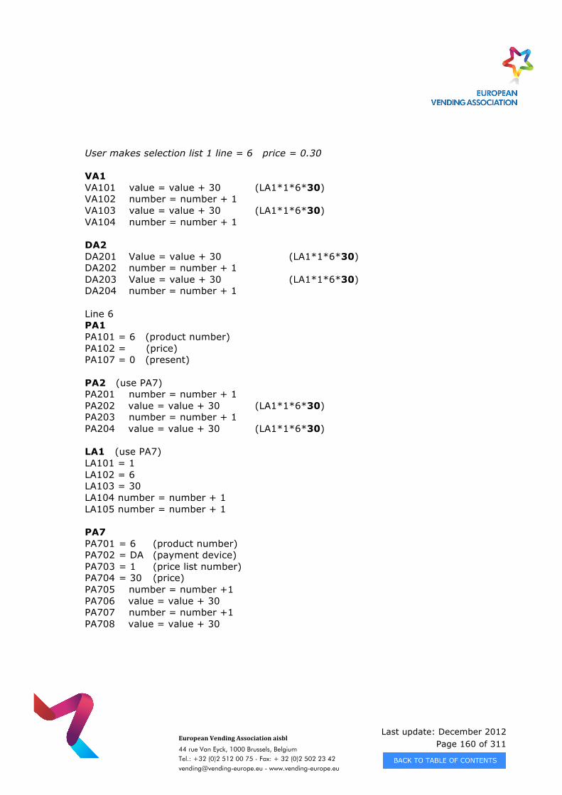
Last update: December 2012 Page 160 of 311
European Vending Association aisbl
44 rue Van Eyck, 1000 Brussels, Belgium Tel.: +32 (0)2 512 00 75 - Fax: + 32 (0)2 502 23 42 [email protected] - www.vending-europe.eu
User makes selection list 1 line = 6 price = 0.30 VA1 VA101 value = value + 30 (LA1*1*6*30) VA102 number = number + 1 VA103 value = value + 30 (LA1*1*6*30) VA104 number = number + 1 DA2 DA201 Value = value + 30 (LA1*1*6*30) DA202 number = number + 1 DA203 Value = value + 30 (LA1*1*6*30) DA204 number = number + 1 Line 6 PA1 PA101 = 6 (product number) PA102 = (price) PA107 = 0 (present) PA2 (use PA7) PA201 number = number + 1 PA202 value = value + 30 (LA1*1*6*30) PA203 number = number + 1 PA204 value = value + 30 (LA1*1*6*30) LA1 (use PA7) LA101 = 1 LA102 = 6 LA103 = 30 LA104 number = number + 1 LA105 number = number + 1 PA7 PA701 = 6 (product number) PA702 = DA (payment device) PA703 = 1 (price list number) PA704 = 30 (price) PA705 number = number +1 PA706 value = value + 30 PA707 number = number +1 PA708 value = value + 30
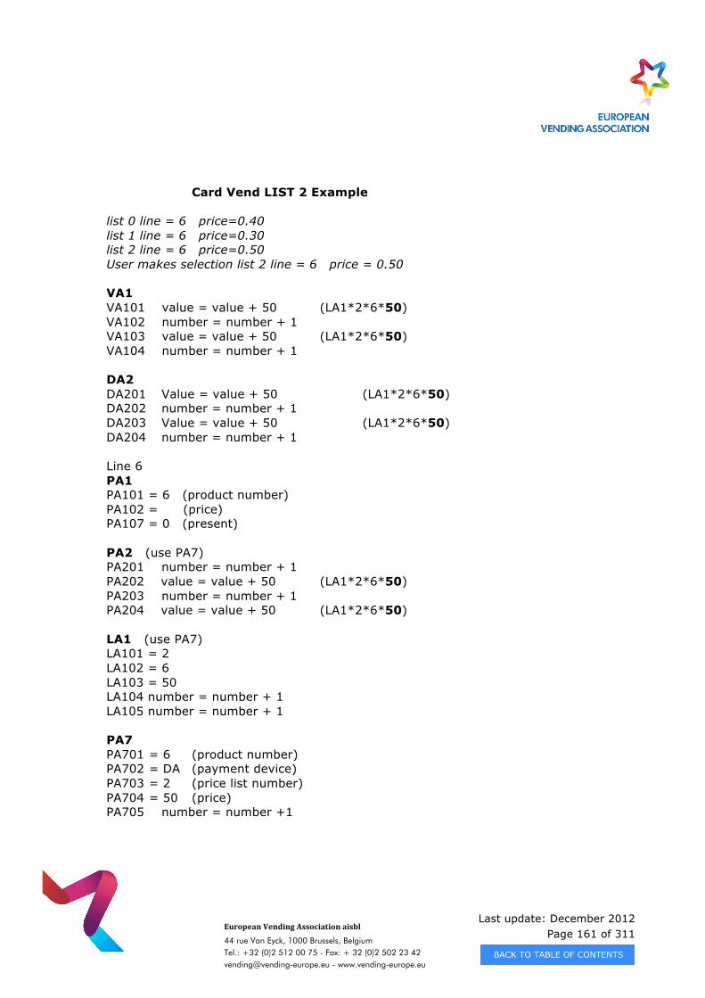
Last update: December 2012 Page 161 of 311
European Vending Association aisbl
44 rue Van Eyck, 1000 Brussels, Belgium Tel.: +32 (0)2 512 00 75 - Fax: + 32 (0)2 502 23 42 [email protected] - www.vending-europe.eu
Card Vend LIST 2 Example list 0 line = 6 price=0.40 list 1 line = 6 price=0.30 list 2 line = 6 price=0.50 User makes selection list 2 line = 6 price = 0.50 VA1 VA101 value = value + 50 (LA1*2*6*50) VA102 number = number + 1 VA103 value = value + 50 (LA1*2*6*50) VA104 number = number + 1 DA2 DA201 Value = value + 50 (LA1*2*6*50) DA202 number = number + 1 DA203 Value = value + 50 (LA1*2*6*50) DA204 number = number + 1 Line 6 PA1 PA101 = 6 (product number) PA102 = (price) PA107 = 0 (present) PA2 (use PA7) PA201 number = number + 1 PA202 value = value + 50 (LA1*2*6*50) PA203 number = number + 1 PA204 value = value + 50 (LA1*2*6*50) LA1 (use PA7) LA101 = 2 LA102 = 6 LA103 = 50 LA104 number = number + 1 LA105 number = number + 1 PA7 PA701 = 6 (product number) PA702 = DA (payment device) PA703 = 2 (price list number) PA704 = 50 (price) PA705 number = number +1
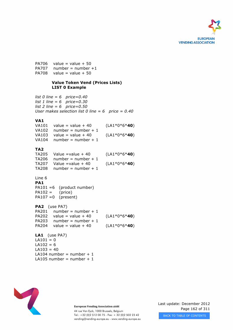
Last update: December 2012 Page 162 of 311
European Vending Association aisbl
44 rue Van Eyck, 1000 Brussels, Belgium Tel.: +32 (0)2 512 00 75 - Fax: + 32 (0)2 502 23 42 [email protected] - www.vending-europe.eu
PA706 value = value + 50 PA707 number = number +1 PA708 value = value + 50
Value Token Vend (Prices Lists) LIST 0 Example
list 0 line = 6 price=0.40 list 1 line = 6 price=0.30 list 2 line = 6 price=0.50 User makes selection list 0 line = 6 price = 0.40 VA1 VA101 value = value + 40 (LA1*0*6*40) VA102 number = number + 1 VA103 value = value + 40 (LA1*0*6*40) VA104 number = number + 1 TA2 TA205 Value =value + 40 (LA1*0*6*40) TA206 number = number + 1 TA207 Value =value + 40 (LA1*0*6*40) TA208 number = number + 1 Line 6 PA1 PA101 =6 (product number) PA102 = (price) PA107 =0 (present) PA2 (use PA7) PA201 number = number + 1 PA202 value = value + 40 (LA1*0*6*40) PA203 number = number + 1 PA204 value = value + 40 (LA1*0*6*40) LA1 (use PA7) LA101 = 0 LA102 = 6 LA103 = 40 LA104 number = number + 1 LA105 number = number + 1
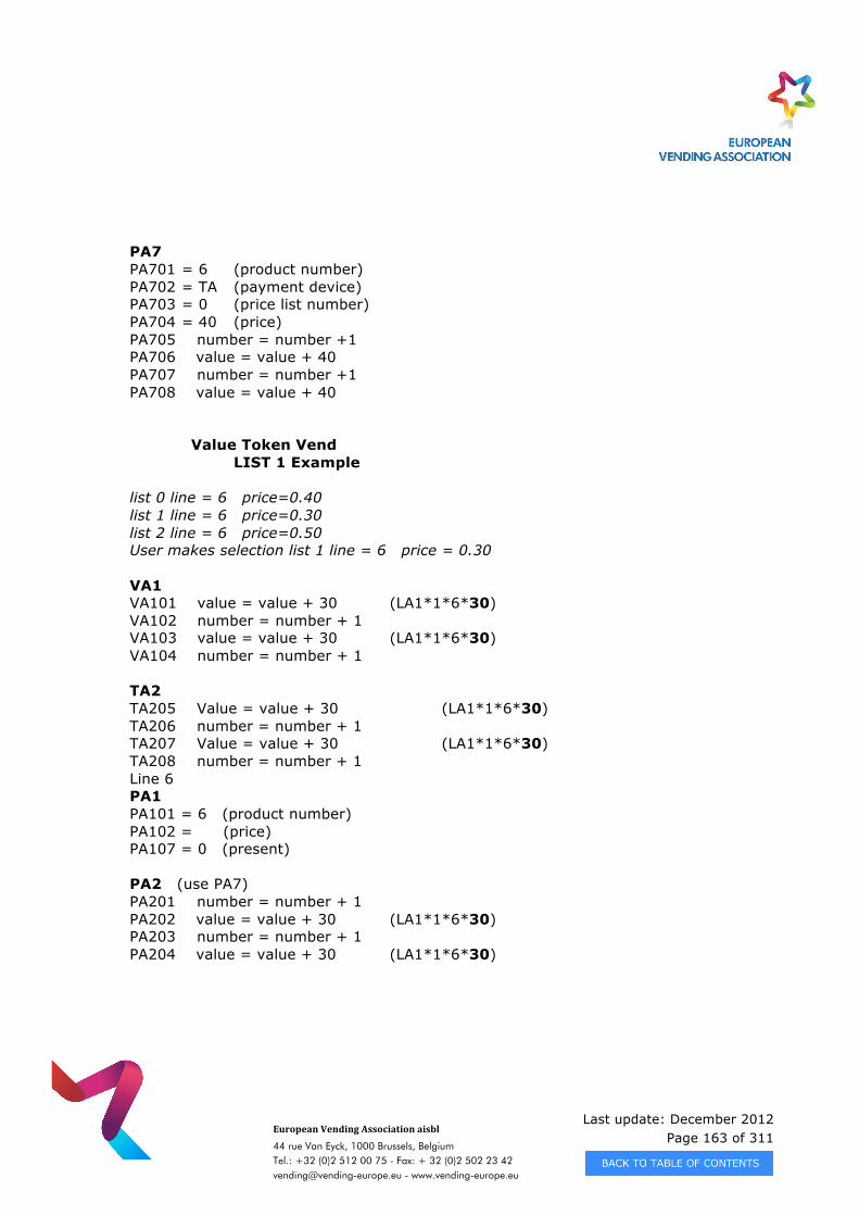
Last update: December 2012 Page 163 of 311
European Vending Association aisbl
44 rue Van Eyck, 1000 Brussels, Belgium Tel.: +32 (0)2 512 00 75 - Fax: + 32 (0)2 502 23 42 [email protected] - www.vending-europe.eu
PA7 PA701 = 6 (product number) PA702 = TA (payment device) PA703 = 0 (price list number) PA704 = 40 (price) PA705 number = number +1 PA706 value = value + 40 PA707 number = number +1 PA708 value = value + 40
Value Token Vend
LIST 1 Example list 0 line = 6 price=0.40 list 1 line = 6 price=0.30 list 2 line = 6 price=0.50 User makes selection list 1 line = 6 price = 0.30 VA1 VA101 value = value + 30 (LA1*1*6*30) VA102 number = number + 1 VA103 value = value + 30 (LA1*1*6*30) VA104 number = number + 1 TA2 TA205 Value = value + 30 (LA1*1*6*30) TA206 number = number + 1 TA207 Value = value + 30 (LA1*1*6*30) TA208 number = number + 1 Line 6 PA1 PA101 = 6 (product number) PA102 = (price) PA107 = 0 (present) PA2 (use PA7) PA201 number = number + 1 PA202 value = value + 30 (LA1*1*6*30) PA203 number = number + 1 PA204 value = value + 30 (LA1*1*6*30)
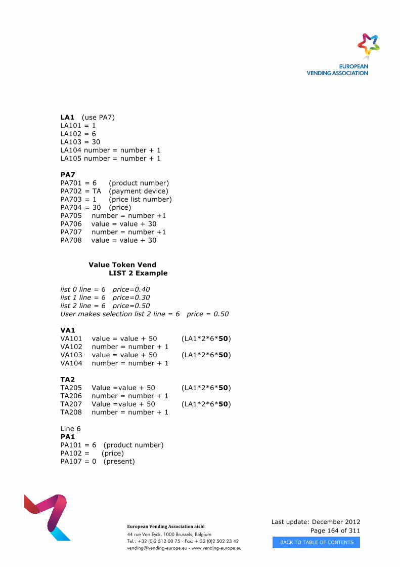
Last update: December 2012 Page 164 of 311
European Vending Association aisbl
44 rue Van Eyck, 1000 Brussels, Belgium Tel.: +32 (0)2 512 00 75 - Fax: + 32 (0)2 502 23 42 [email protected] - www.vending-europe.eu
LA1 (use PA7) LA101 = 1 LA102 = 6 LA103 = 30 LA104 number = number + 1 LA105 number = number + 1 PA7 PA701 = 6 (product number) PA702 = TA (payment device) PA703 = 1 (price list number) PA704 = 30 (price) PA705 number = number +1 PA706 value = value + 30 PA707 number = number +1 PA708 value = value + 30
Value Token Vend
LIST 2 Example list 0 line = 6 price=0.40 list 1 line = 6 price=0.30 list 2 line = 6 price=0.50 User makes selection list 2 line = 6 price = 0.50 VA1 VA101 value = value + 50 (LA1*2*6*50) VA102 number = number + 1 VA103 value = value + 50 (LA1*2*6*50) VA104 number = number + 1 TA2 TA205 Value =value + 50 (LA1*2*6*50) TA206 number = number + 1 TA207 Value =value + 50 (LA1*2*6*50) TA208 number = number + 1 Line 6 PA1 PA101 = 6 (product number) PA102 = (price) PA107 = 0 (present)
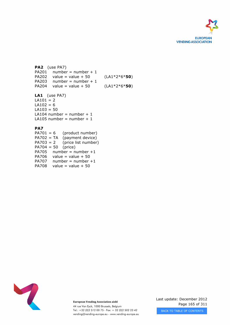
Last update: December 2012 Page 165 of 311
European Vending Association aisbl
44 rue Van Eyck, 1000 Brussels, Belgium Tel.: +32 (0)2 512 00 75 - Fax: + 32 (0)2 502 23 42 [email protected] - www.vending-europe.eu
PA2 (use PA7) PA201 number = number + 1 PA202 value = value + 50 (LA1*2*6*50) PA203 number = number + 1 PA204 value = value + 50 (LA1*2*6*50) LA1 (use PA7) LA101 = 2 LA102 = 6 LA103 = 50 LA104 number = number + 1 LA105 number = number + 1 PA7 PA701 = 6 (product number) PA702 = TA (payment device) PA703 = 2 (price list number) PA704 = 50 (price) PA705 number = number +1 PA706 value = value + 50 PA707 number = number +1 PA708 value = value + 50
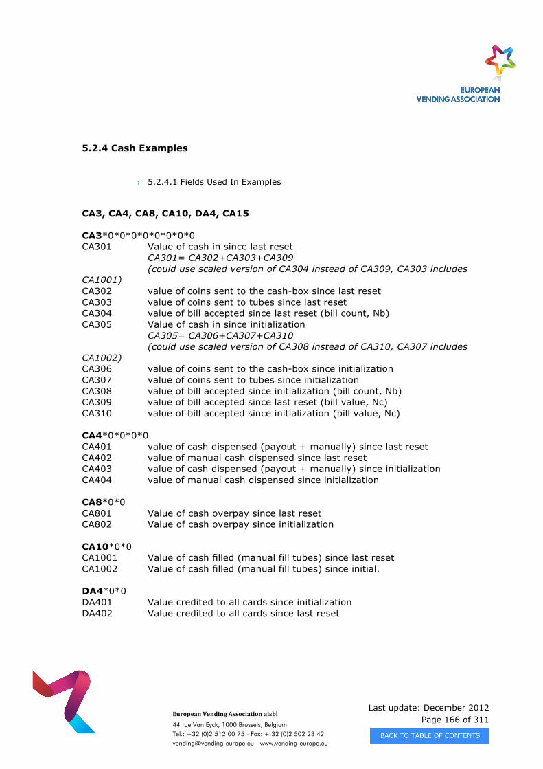
Last update: December 2012 Page 166 of 311
European Vending Association aisbl
44 rue Van Eyck, 1000 Brussels, Belgium Tel.: +32 (0)2 512 00 75 - Fax: + 32 (0)2 502 23 42 [email protected] - www.vending-europe.eu
5.2.4 Cash Examples
› 5.2.4.1 Fields Used In Examples
CA3, CA4, CA8, CA10, DA4, CA15 CA3*0*0*0*0*0*0*0*0 CA301 Value of cash in since last reset CA301= CA302+CA303+CA309 (could use scaled version of CA304 instead of CA309, CA303 includes CA1001) CA302 value of coins sent to the cash-box since last reset CA303 value of coins sent to tubes since last reset CA304 value of bill accepted since last reset (bill count, Nb) CA305 Value of cash in since initialization CA305= CA306+CA307+CA310 (could use scaled version of CA308 instead of CA310, CA307 includes CA1002) CA306 value of coins sent to the cash-box since initialization CA307 value of coins sent to tubes since initialization CA308 value of bill accepted since initialization (bill count, Nb) CA309 value of bill accepted since last reset (bill value, Nc) CA310 value of bill accepted since initialization (bill value, Nc) CA4*0*0*0*0 CA401 value of cash dispensed (payout + manually) since last reset CA402 value of manual cash dispensed since last reset CA403 value of cash dispensed (payout + manually) since initialization CA404 value of manual cash dispensed since initialization CA8*0*0 CA801 Value of cash overpay since last reset CA802 Value of cash overpay since initialization CA10*0*0 CA1001 Value of cash filled (manual fill tubes) since last reset CA1002 Value of cash filled (manual fill tubes) since initial. DA4*0*0 DA401 Value credited to all cards since initialization DA402 Value credited to all cards since last reset
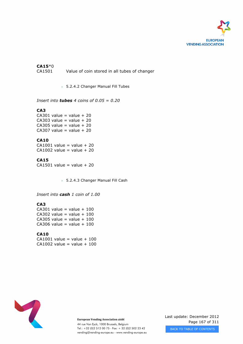
Last update: December 2012 Page 167 of 311
European Vending Association aisbl
44 rue Van Eyck, 1000 Brussels, Belgium Tel.: +32 (0)2 512 00 75 - Fax: + 32 (0)2 502 23 42 [email protected] - www.vending-europe.eu
CA15*0 CA1501 Value of coin stored in all tubes of changer
› 5.2.4.2 Changer Manual Fill Tubes
Insert into tubes 4 coins of 0.05 = 0.20 CA3 CA301 value = value + 20 CA303 value = value + 20 CA305 value = value + 20 CA307 value = value + 20 CA10 CA1001 value = value + 20 CA1002 value = value + 20 CA15 CA1501 value = value + 20
› 5.2.4.3 Changer Manual Fill Cash
Insert into cash 1 coin of 1.00 CA3 CA301 value = value + 100 CA302 value = value + 100 CA305 value = value + 100 CA306 value = value + 100 CA10 CA1001 value = value + 100 CA1002 value = value + 100
Last update: December 2012 Page 168 of 311
European Vending Association aisbl
44 rue Van Eyck, 1000 Brussels, Belgium Tel.: +32 (0)2 512 00 75 - Fax: + 32 (0)2 502 23 42 [email protected] - www.vending-europe.eu
› 5.2.4.4 Changer Manual Dispensed
Dispense from tubes 2 coins of 0.05= 0.10 CA4 CA401 value = value + 10 CA402 value = value + 10 CA403 value = value + 10 CA404 value = value + 10 CA15 CA1501 value = value - 10
› 5.2.4.5 Insert Coin Into Cash-Box
Insert into cash 1 coin 1.00 CA3 CA301 value = value + 100 CA302 value = value + 100 CA305 value = value + 100 CA306 value = value + 100 5.2.4.6 Insert Coin Into Tubes Insert into tubes 3 coins 0.10 = 0.30 CA3 CA301 value = value + 30 CA303 value = value + 30 CA305 value = value + 30 CA307 value = value + 30 CA15 CA1501 value = value + 30
Last update: December 2012 Page 169 of 311
European Vending Association aisbl
44 rue Van Eyck, 1000 Brussels, Belgium Tel.: +32 (0)2 512 00 75 - Fax: + 32 (0)2 502 23 42 [email protected] - www.vending-europe.eu
› 5.2.4.7 Escrow (Dispensed Coins)
Dispense from tubes 3 coins 0.10 = 0.30 CA4 CA401 value = value + 30 CA403 value = value + 30 CA15 CA1501 value = value - 30
› 5.2.4.8 Overpay
Insert into cash 1 coin =1.00 vend price = 0.40 change payout = 0.50 (from tubes) overpay = 0.10 CA3 CA301 value = value +100 CA302 value = value +100 CA305 value = value +100 CA306 value = value +100 CA4 CA401 value = value +50 CA403 value = value +50 CA8 CA801 value = value +10 CA802 value = value +10 CA15 CA1501 value = value – 50
› 5.2.4.9 Card Revalue
Insert into cash 1 coin 1.00 = 1.00 Insert into tubes 2 coins 0.10 = 0.20
Last update: December 2012 Page 170 of 311
European Vending Association aisbl
44 rue Van Eyck, 1000 Brussels, Belgium Tel.: +32 (0)2 512 00 75 - Fax: + 32 (0)2 502 23 42 [email protected] - www.vending-europe.eu
CA3 CA301 value = value + 120 CA302 value = value + 100 CA303 value = value + 20 CA305 value = value + 120 CA306 value = value + 100 CA307 value = value + 20 DA4 DA401 value = value + 120 DA402 value = value + 120 CA15 CA1501 value = value + 20
› 5.2.4.10 Insert Banknote
Insert 1 banknote 5.00 CA3 (assumes ID401 is equal to 2) CA301 value = value + 500 CA304 value = value + 5 (N0) CA305 value = value + 500 CA308 value = value + 5 (N0) CA309 value = value + 500 CA310 value = value + 500
Last update: December 2012 Page 171 of 311
European Vending Association aisbl
44 rue Van Eyck, 1000 Brussels, Belgium Tel.: +32 (0)2 512 00 75 - Fax: + 32 (0)2 502 23 42 [email protected] - www.vending-europe.eu
CHAPTER 6 - APPLICATION NOTES - DDCMP
6.1 APPLICATION NOTES FOR THE ENHANCED DDCMP
This section of the document is intended to be read with Chapter 3, Data transfer using Enhanced DDCMP, and is an explanation and application guide to a number of points. When reading this chapter it should be noted that it is purely advisory in nature and in no part substitutes for the actual standard which is fully defined in Chapter 3. All chapter, section, subsection etc. numbers in this section of the document refer to the above mentioned chapter.
6.1.1 Byte Format (see 3.4.1.2 and 3.6.4.1.1)
There are several conventions used in current applications, when transmitting fixed size Binary Data without explicit delimiters. These are highlighted in the table below.
Data Type Transfer Order
Multi – Byte Values Transmitted least significant byte first, unless described otherwise.
Date Value Transmitted as a three byte value, held in binary coded decimal, (i.e. 2 digits per byte), in the order DDMMYY.
Time Value Transmitted as a three-byte value, held in binary coded decimal form in the order hhmmss.
Security Codes Transmitted as a four-byte value ms byte first. With reference to 3.6.4.1.1, the order is S2S1 P2P1.
User Identity Transmitted as a two-byte value ms byte first in alphanumeric format.
Machine Serial Number Transmitted as an 8-bit ASCII string with the most significant digit first. For the ASCII format see 2.3.2.
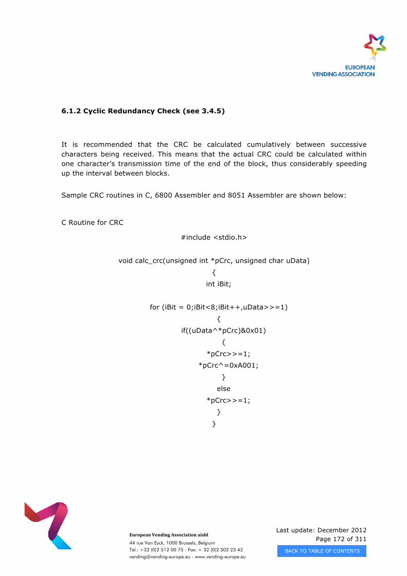
Last update: December 2012 Page 172 of 311
European Vending Association aisbl
44 rue Van Eyck, 1000 Brussels, Belgium Tel.: +32 (0)2 512 00 75 - Fax: + 32 (0)2 502 23 42 [email protected] - www.vending-europe.eu
6.1.2 Cyclic Redundancy Check (see 3.4.5)
It is recommended that the CRC be calculated cumulatively between successive characters being received. This means that the actual CRC could be calculated within one character’s transmission time of the end of the block, thus considerably speeding up the interval between blocks. Sample CRC routines in C, 6800 Assembler and 8051 Assembler are shown below:
C Routine for CRC
#include <stdio.h>
void calc_crc(unsigned int *pCrc, unsigned char uData)
{
int iBit;
for (iBit = 0;iBit<8;iBit++,uData>>=1)
{
if((uData^*pCrc)&0x01)
{
*pCrc>>=1;
*pCrc^=0xA001;
}
else
*pCrc>>=1;
}
}
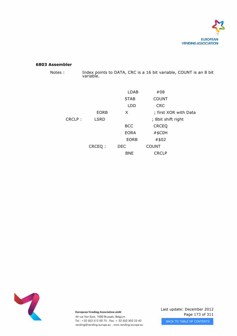
Last update: December 2012 Page 173 of 311
European Vending Association aisbl
44 rue Van Eyck, 1000 Brussels, Belgium Tel.: +32 (0)2 512 00 75 - Fax: + 32 (0)2 502 23 42 [email protected] - www.vending-europe.eu
6803 Assembler
Notes : Index points to DATA, CRC is a 16 bit variable, COUNT is an 8 bit variable.
LDAB #08
STAB COUNT
LDD CRC
EORB X ; first XOR with Data
CRCLP : LSRD ; 8bit shift right
BCC CRCEQ
EORA #$C0H
EORB #$02
CRCEQ : DEC COUNT
BNE CRCLP
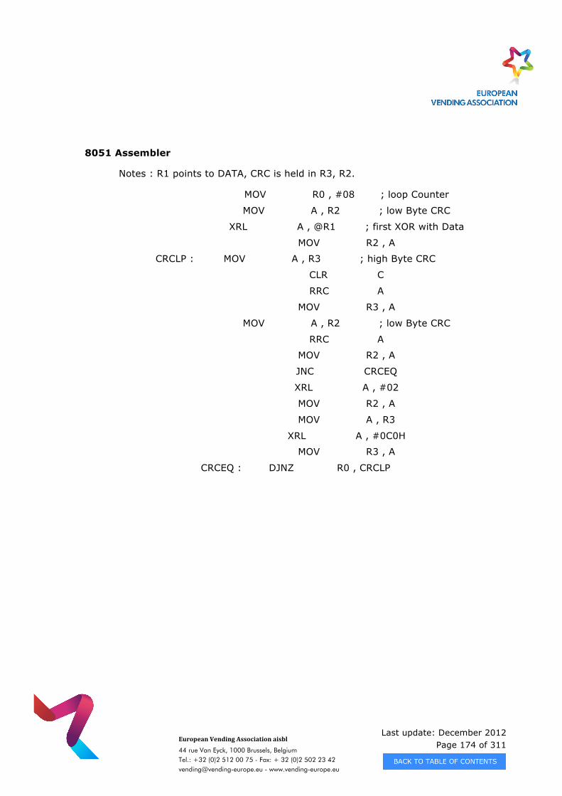
Last update: December 2012 Page 174 of 311
European Vending Association aisbl
44 rue Van Eyck, 1000 Brussels, Belgium Tel.: +32 (0)2 512 00 75 - Fax: + 32 (0)2 502 23 42 [email protected] - www.vending-europe.eu
8051 Assembler
Notes : R1 points to DATA, CRC is held in R3, R2.
MOV R0 , #08 ; loop Counter
MOV A , R2 ; low Byte CRC
XRL A , @R1 ; first XOR with Data
MOV R2 , A
CRCLP : MOV A , R3 ; high Byte CRC
CLR C
RRC A
MOV R3 , A
MOV A , R2 ; low Byte CRC
RRC A
MOV R2 , A
JNC CRCEQ
XRL A , #02
MOV R2 , A
MOV A , R3
XRL A , #0C0H
MOV R3 , A
CRCEQ : DJNZ R0 , CRCLP
Last update: December 2012 Page 175 of 311
European Vending Association aisbl
44 rue Van Eyck, 1000 Brussels, Belgium Tel.: +32 (0)2 512 00 75 - Fax: + 32 (0)2 502 23 42 [email protected] - www.vending-europe.eu
6.1.3 Enhanced DDCMP Features
Communication between the Master and Slave has the following variation to standard DDCMP features: - One of the flags (bit 7 of the third byte – the select flag) in the header for data
messages has been used as a ’Last Message’ flag. The purpose of this is for the station transmitting a data message to indicate that the right to transmit a data message may be transferred to the other station on completion of the current message. This is used, for example, to allow the Master to transmit the audit data as a sequence of data messages each with the select flag cleared except in the last one.
Current implementations of the Enhanced DDCMP have to take notice of the value of the select flag. Old implementations of the protocol do not take any notice of the value
of the select flag, although it should be noted that the value of the flag might alter according to which activity is in progress at which point in the system.
Thus the Data Carrier communications with the vending machine may not toggle the flag, whilst those between the PC and the Data Carrier may toggle the flag.
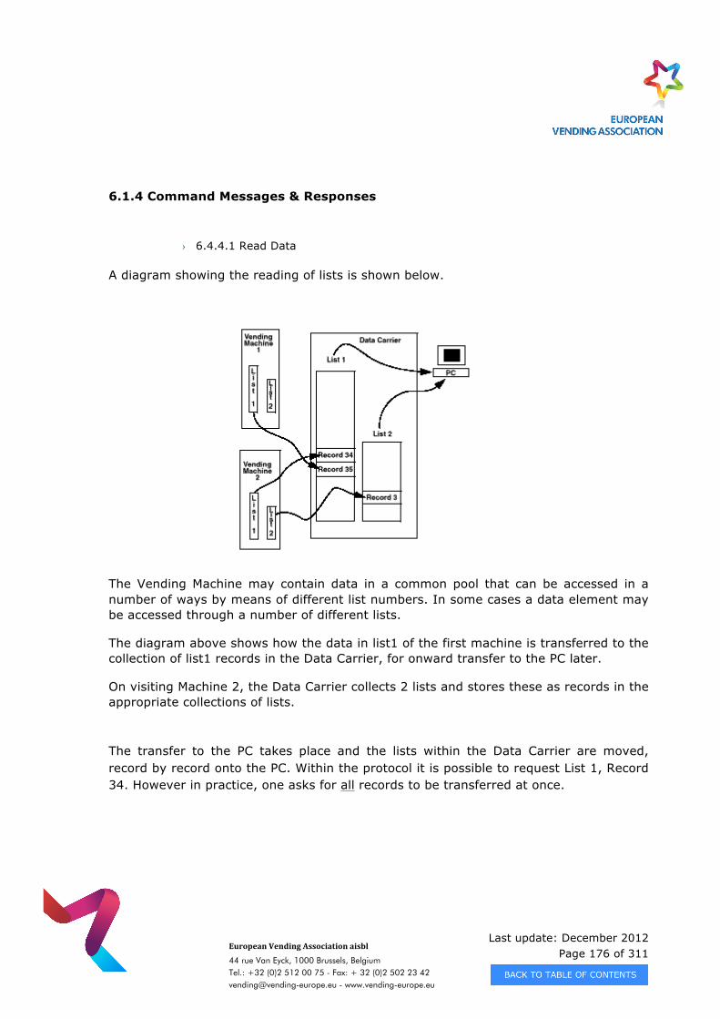
Last update: December 2012 Page 176 of 311
European Vending Association aisbl
44 rue Van Eyck, 1000 Brussels, Belgium Tel.: +32 (0)2 512 00 75 - Fax: + 32 (0)2 502 23 42 [email protected] - www.vending-europe.eu
6.1.4 Command Messages & Responses
› 6.4.4.1 Read Data
A diagram showing the reading of lists is shown below.
The Vending Machine may contain data in a common pool that can be accessed in a number of ways by means of different list numbers. In some cases a data element may be accessed through a number of different lists.
The diagram above shows how the data in list1 of the first machine is transferred to the collection of list1 records in the Data Carrier, for onward transfer to the PC later.
On visiting Machine 2, the Data Carrier collects 2 lists and stores these as records in the appropriate collections of lists.
The transfer to the PC takes place and the lists within the Data Carrier are moved, record by record onto the PC. Within the protocol it is possible to request List 1, Record 34. However in practice, one asks for all records to be transferred at once.
Last update: December 2012 Page 177 of 311
European Vending Association aisbl
44 rue Van Eyck, 1000 Brussels, Belgium Tel.: +32 (0)2 512 00 75 - Fax: + 32 (0)2 502 23 42 [email protected] - www.vending-europe.eu
› 6.1.4.2 Delete Data (see 3.6.4.1.5)
This command is used at the end of a data transfer from the Data Carrier to the PC to allow the PC to indicate to the Data Carrier that the records have both been transferred and stored safely. The Data Carrier then marks the transferred information as being disposable but does not actually delete the data until the space is needed. This allows the PC to re-read the information into a different file, or allows the user to restart the whole process with another PC in case of damage or file corruption of the first copy of the transferred data. 6.1.5 Message Sequences - End of Communications Sequence (see 3.6.4.1.8)
In the pre December 1990 implementation of the optical link it is possible under an Operator induced fault condition to cease transmission without successfully resetting the interims within the Vending Machine. This then results in the values being reported again next week before being reset. The Totals are not affected by the Operator induced fault. The present implementation sends an ACK + FINISH at the end of the sequence and after the last data message. If the Operator has removed the Data Collector from the vicinity of the Vending Machine before these have been received, then the Interims are not reset. The Data Collector is unaware that the Interims have not been reset due to an incomplete communication session. The agreed solution is to have the Vending Machine acknowledge the receipt of the FINISH command by sending an ACK to the Data Carrier. The Vending Machine marks the data as ready to reset & resets it at the next paid vend. The Data Carrier transfers the list just received from a Pending List to the true list on receipt of the ACK. This can be illustrated:
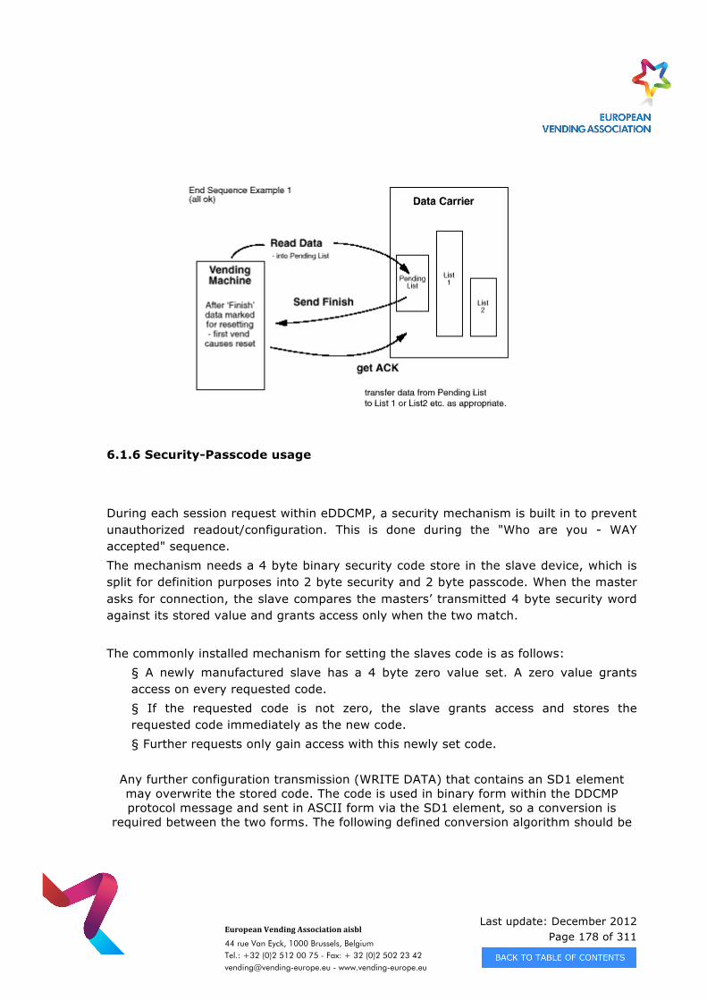
Last update: December 2012 Page 178 of 311
European Vending Association aisbl
44 rue Van Eyck, 1000 Brussels, Belgium Tel.: +32 (0)2 512 00 75 - Fax: + 32 (0)2 502 23 42 [email protected] - www.vending-europe.eu
6.1.6 Security-Passcode usage
During each session request within eDDCMP, a security mechanism is built in to prevent unauthorized readout/configuration. This is done during the "Who are you - WAY accepted" sequence. The mechanism needs a 4 byte binary security code store in the slave device, which is split for definition purposes into 2 byte security and 2 byte passcode. When the master asks for connection, the slave compares the masters’ transmitted 4 byte security word against its stored value and grants access only when the two match. The commonly installed mechanism for setting the slaves code is as follows:
§ A newly manufactured slave has a 4 byte zero value set. A zero value grants access on every requested code. § If the requested code is not zero, the slave grants access and stores the requested code immediately as the new code. § Further requests only gain access with this newly set code.
Any further configuration transmission (WRITE DATA) that contains an SD1 element may overwrite the stored code. The code is used in binary form within the DDCMP protocol message and sent in ASCII form via the SD1 element, so a conversion is
required between the two forms. The following defined conversion algorithm should be
Last update: December 2012 Page 179 of 311
European Vending Association aisbl
44 rue Van Eyck, 1000 Brussels, Belgium Tel.: +32 (0)2 512 00 75 - Fax: + 32 (0)2 502 23 42 [email protected] - www.vending-europe.eu
used if the first character of the SD101 or SD102 element starts with uppercase ASCII letter 'X', otherwise the conversion algorithm is manufacturer specific.
The value (32 bit, i.e. 4 byte number) is represented in HEX ASCII form (with all alpha characters in uppercase) e.g. HEX value 01 02 03 04 (which corresponds to a decimal
value of 16909060) is represented by "X01020304" hence a password of 01 02 03 04 can be
changed to a new password AA 00 EF 21 by sending the following message SD1*X01020304*XAA00EF21, where the format is MS Byte first i.e. 0x58(‘X’), 0xAA,
0x00, OxEF and 0x21.
Note: All new products should support the defined algorithm but data carriers should be aware of and support earlier implementations that have manufacturer specific
algorithms.
6.1.7 Configuration features
To avoid any unauthorised setting of configuration data, it is common for vending machine controllers to use other methods as well as checking the pass/security code. Essentially, the Security/passcode matching is sufficient for any readout of data, but when configuring the settings, controllers also check whether the door is open at the same time. This can be done either by using a door switch or by the pressing of internal function keys on the controller. 6.1.8 Slave address setting
Each device using enhanced DDCMP has a default slave address set. There must be a mechanism built in to each device, to allow the changing of the slave address from default to one of the individual free addresses. This is in the event that more than one device in the system is using the same address.
Last update: December 2012 Page 180 of 311
European Vending Association aisbl
44 rue Van Eyck, 1000 Brussels, Belgium Tel.: +32 (0)2 512 00 75 - Fax: + 32 (0)2 502 23 42 [email protected] - www.vending-europe.eu
6.2 EXAMPLE COMMUNICATION SEQUENCES
This section of the application notes will show examples of various common message sequences as well as erroneous sequences and how to handle them.
6.2.1 Standard Data Collection Examples
The most common form of Data Collection is Audit collection. This is generally used on a periodic (weekly) basis to keep the Vending Machine configuration settings up to date and to acquire any data generated by the machine since the last Audit Collection. This activity will usually be carried out by the Route Person as part of their routine visit to the machine. All Interims, i.e. resettable values, are reset to zero after such a collection, on the first vend completed after a FINISH is received by the Vending Machine. The type of data collection is set by the list number, with Audit collection being list number 1. Other possible forms of Data Collection are :
· Security Collection (List No. 2) · Machine Configuration List (List No. 64) · Dump List (List No. 50)
Note that, with the exception of START, STACK, ACK and NACK messages, all messages are formed using a Data Message Header together with the necessary command / data suffixes. For example, a Finish command with header would be sent as follows:
81 02 40 05 03 01 A3 20 77 FF 67 B0 where · the first 8 bytes are the Message Header (see section 3.6.3). · the last 4 bytes are the actual FINISH command (See section 3.6.4.1.8). The following examples show several standard message sequences for Audit with and without configuration, assuming error free transmission of all messages. In all of the these examples, where Rx and Tx numbers are shown, these refer to the sequence numbers in the Data Header (see 3.6.3) and the ACK and NACK (3.6.2) messages. These counts are maintained by both the transmitting and receiving stations.
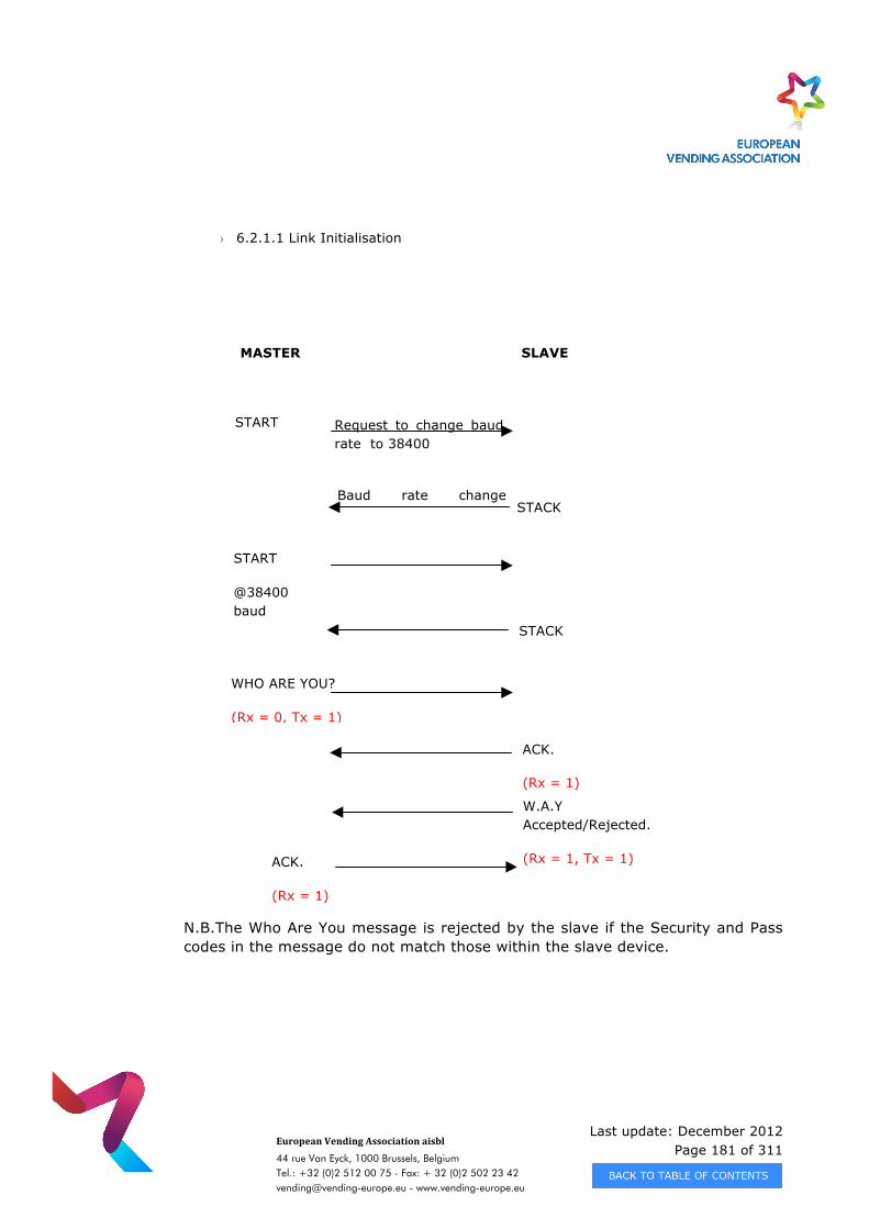
Last update: December 2012 Page 181 of 311
European Vending Association aisbl
44 rue Van Eyck, 1000 Brussels, Belgium Tel.: +32 (0)2 512 00 75 - Fax: + 32 (0)2 502 23 42 [email protected] - www.vending-europe.eu
› 6.2.1.1 Link Initialisation
N.B.The Who Are You message is rejected by the slave if the Security and Pass codes in the message do not match those within the slave device.
1.1.2 2400 baud
1.1.1 38400 baud
MASTER SLAVE
START
@2400 baud
STACK
Request to change baud rate to 38400
ACK.
(Rx = 1)
START
@38400 baud
STACK
Baud rate change confirmed.
WHO ARE YOU?
(Rx = 0, Tx = 1)
W.A.Y Accepted/Rejected.
(Rx = 1, Tx = 1) ACK.
(Rx = 1)
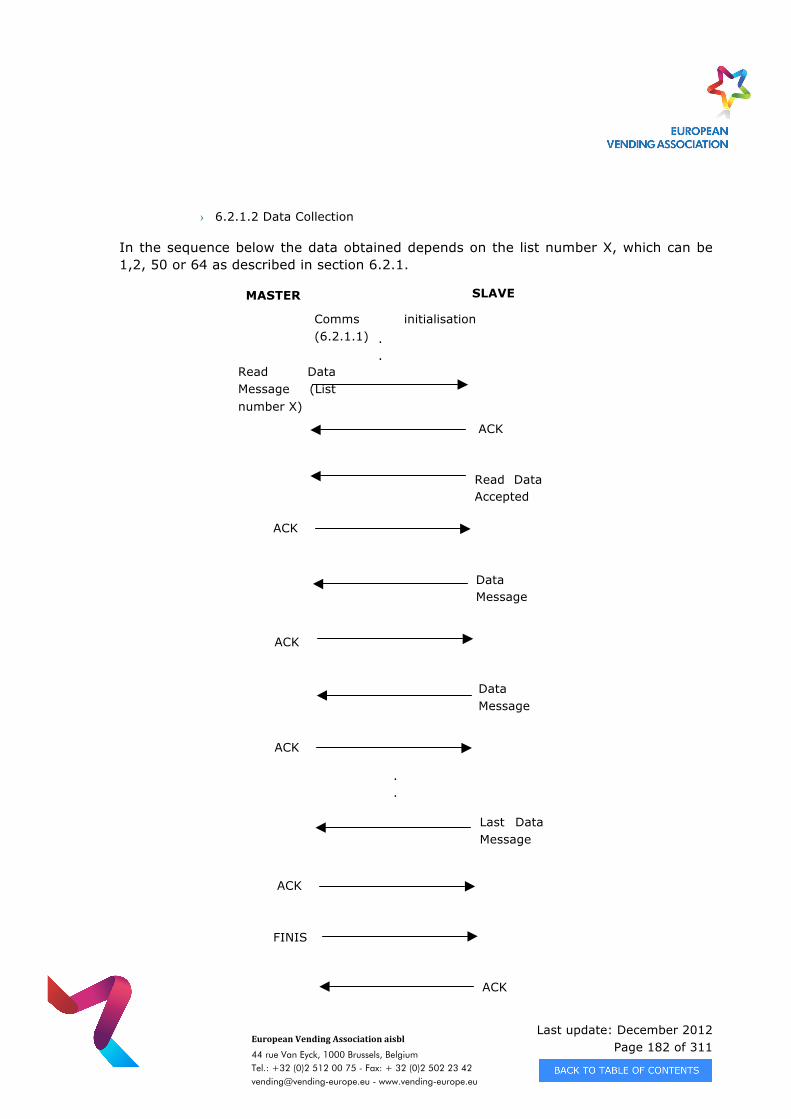
Last update: December 2012 Page 182 of 311
European Vending Association aisbl
44 rue Van Eyck, 1000 Brussels, Belgium Tel.: +32 (0)2 512 00 75 - Fax: + 32 (0)2 502 23 42 [email protected] - www.vending-europe.eu
› 6.2.1.2 Data Collection
In the sequence below the data obtained depends on the list number X, which can be 1,2, 50 or 64 as described in section 6.2.1.
Comms initialisation (6.2.1.1) .
.
.
.
.
.
MASTER SLAVE
Read Data Message (List number X)
ACK
Data Message
Read Data Accepted
Data Message
ACK
ACK
ACK
.
.
.
.
.
.
Last Data Message
ACK
FINISH
ACK
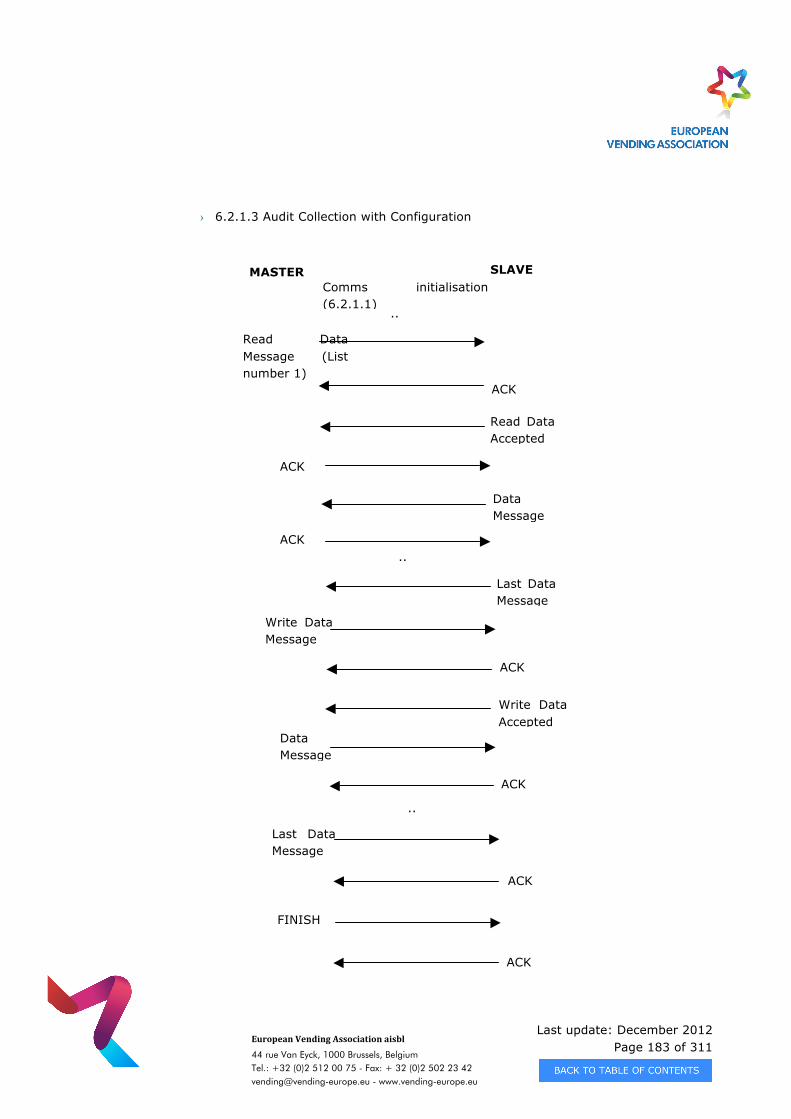
Last update: December 2012 Page 183 of 311
European Vending Association aisbl
44 rue Van Eyck, 1000 Brussels, Belgium Tel.: +32 (0)2 512 00 75 - Fax: + 32 (0)2 502 23 42 [email protected] - www.vending-europe.eu
› 6.2.1.3 Audit Collection with Configuration
Comms initialisation (6.2.1.1)
..
..
MASTER SLAVE
Write Data Message
ACK
Write Data Accepted
Data Message
ACK
ACK
..
.. Last Data Message
FINISH
ACK
Read Data Message (List number 1)
ACK
Read Data Accepted
Data Message
ACK
ACK ..
.. Last Data Message
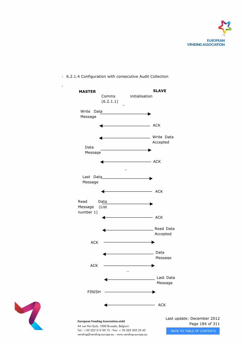
Last update: December 2012 Page 184 of 311
European Vending Association aisbl
44 rue Van Eyck, 1000 Brussels, Belgium Tel.: +32 (0)2 512 00 75 - Fax: + 32 (0)2 502 23 42 [email protected] - www.vending-europe.eu
› 6.2.1.4 Configuration with consecutive Audit Collection
›
Comms initialisation (6.2.1.1)
..
..
MASTER SLAVE
Write Data Message
ACK
Write Data Accepted
Data Message
ACK
ACK
..
.. Last Data Message
FINISH
ACK
Last Data Message
Read Data Message (List number 1)
ACK
Read Data Accepted
Data Message
ACK
ACK ..
..
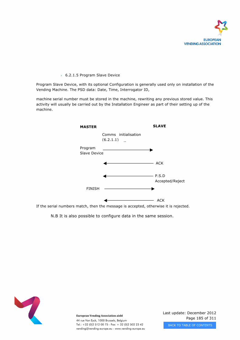
Last update: December 2012 Page 185 of 311
European Vending Association aisbl
44 rue Van Eyck, 1000 Brussels, Belgium Tel.: +32 (0)2 512 00 75 - Fax: + 32 (0)2 502 23 42 [email protected] - www.vending-europe.eu
› 6.2.1.5 Program Slave Device
Program Slave Device, with its optional Configuration is generally used only on installation of the Vending Machine. The PSD data: Date, Time, Interrogator ID,
machine serial number must be stored in the machine, rewriting any previous stored value. This activity will usually be carried out by the Installation Engineer as part of their setting up of the machine.
If the serial numbers match, then the message is accepted, otherwise it is rejected.
N.B It is also possible to configure data in the same session.
Comms initialisation (6.2.1.1) ..
..
MASTER SLAVE
Program Slave Device
ACK
P.S.D Accepted/Rejected
ACK
FINISH
Last update: December 2012 Page 186 of 311
European Vending Association aisbl
44 rue Van Eyck, 1000 Brussels, Belgium Tel.: +32 (0)2 512 00 75 - Fax: + 32 (0)2 502 23 42 [email protected] - www.vending-europe.eu
› 6.2.1.6 Security Collection
Security collection, although infrequently used, takes a ’snapshot’ of the Vending Machine settings and data generated by the machine since the last Audit Collection. This activity will usually be carried out by the Route Supervisor as part of a special visit to the machine. All Interims, i.e. resettable values are left unchanged after such a collection. Basically, the only difference between this and an audit collection is the list number therefore simply substitute 2 for X in the diagram shown in 6.2.1.2.
› 6.2.1.6 Dump list collection
Dump list is the collection of all data stored in the machine needed to make a copy of the machine itself, for example before changing the CPU board, or to set-up equal machines at the end of the production line. For example, a dump list can be built by chaining together audit list and configuration data. Collecting a dump list is the same as the data collection shown in 6.2.1.2, substituting 50 for X.
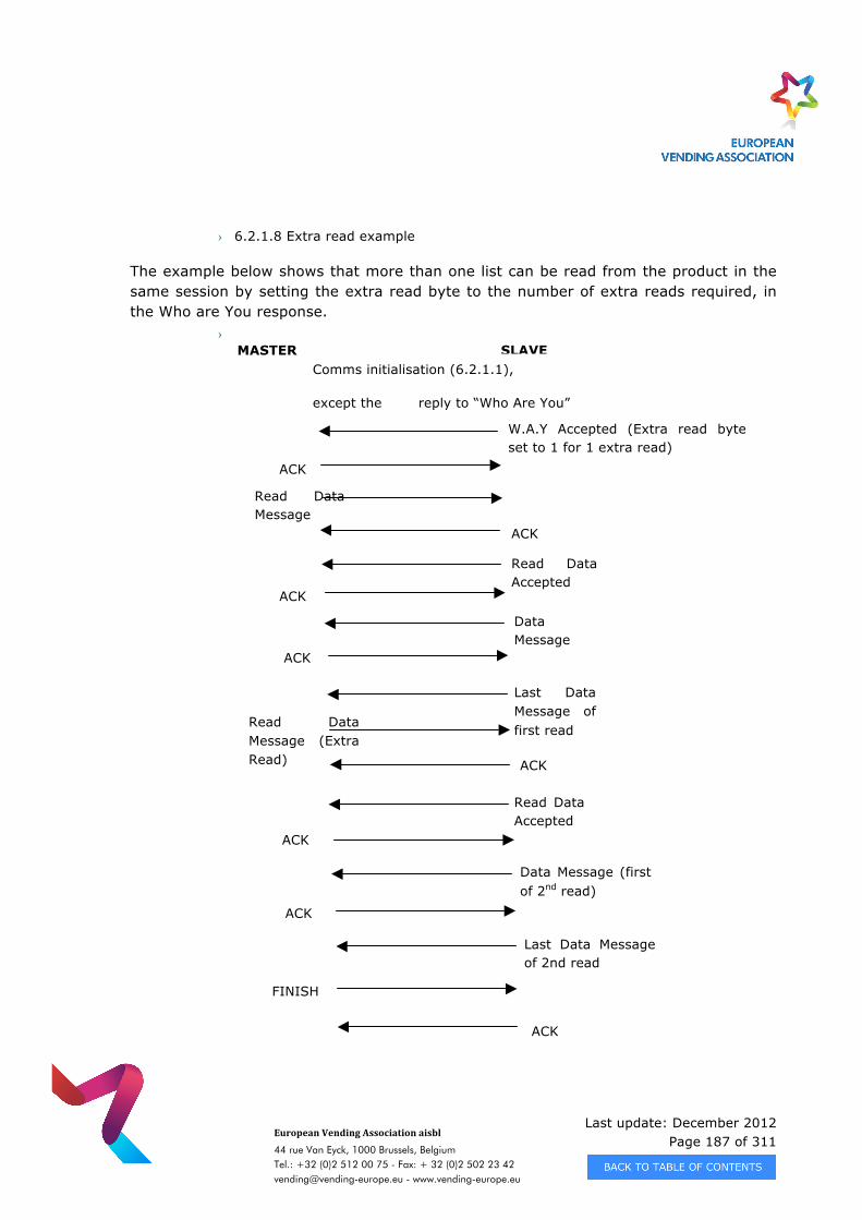
Last update: December 2012 Page 187 of 311
European Vending Association aisbl
44 rue Van Eyck, 1000 Brussels, Belgium Tel.: +32 (0)2 512 00 75 - Fax: + 32 (0)2 502 23 42 [email protected] - www.vending-europe.eu
› 6.2.1.8 Extra read example
The example below shows that more than one list can be read from the product in the same session by setting the extra read byte to the number of extra reads required, in the Who are You response.
› MASTER SLAVE
W.A.Y Accepted (Extra read byte set to 1 for 1 extra read)
ACK
Read Data Message
ACK
Read Data Accepted
Data Message
Last Data Message of first read
ACK
ACK
Comms initialisation (6.2.1.1),
except the reply to “Who Are You”
Read Data Message (Extra Read) ACK
Read Data Accepted
Data Message (first of 2nd read)
Last Data Message of 2nd read
ACK
ACK
ACK
FINISH
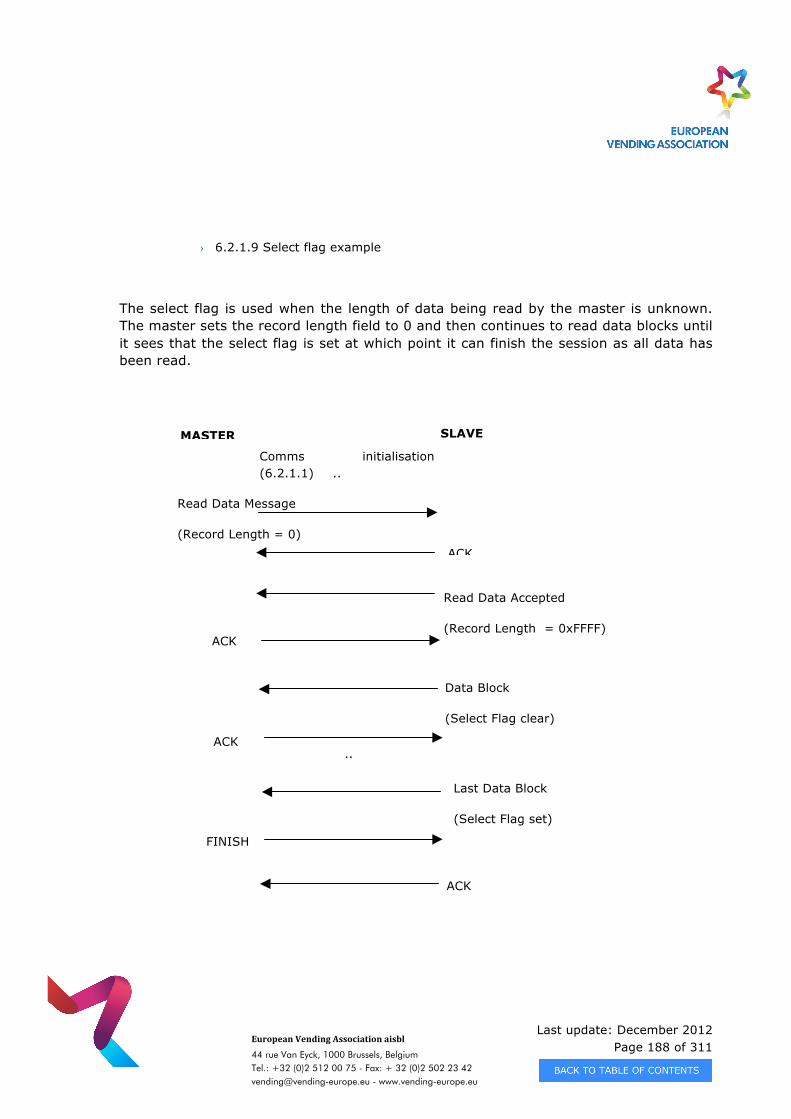
Last update: December 2012 Page 188 of 311
European Vending Association aisbl
44 rue Van Eyck, 1000 Brussels, Belgium Tel.: +32 (0)2 512 00 75 - Fax: + 32 (0)2 502 23 42 [email protected] - www.vending-europe.eu
› 6.2.1.9 Select flag example
The select flag is used when the length of data being read by the master is unknown. The master sets the record length field to 0 and then continues to read data blocks until it sees that the select flag is set at which point it can finish the session as all data has been read.
Comms initialisation (6.2.1.1) ..
..
..
MASTER SLAVE
Read Data Message
(Record Length = 0) ACK
Read Data Accepted
(Record Length = 0xFFFF)
Data Block
(Select Flag clear)
ACK
ACK ..
..
..
Last Data Block
(Select Flag set)
FINISH
ACK
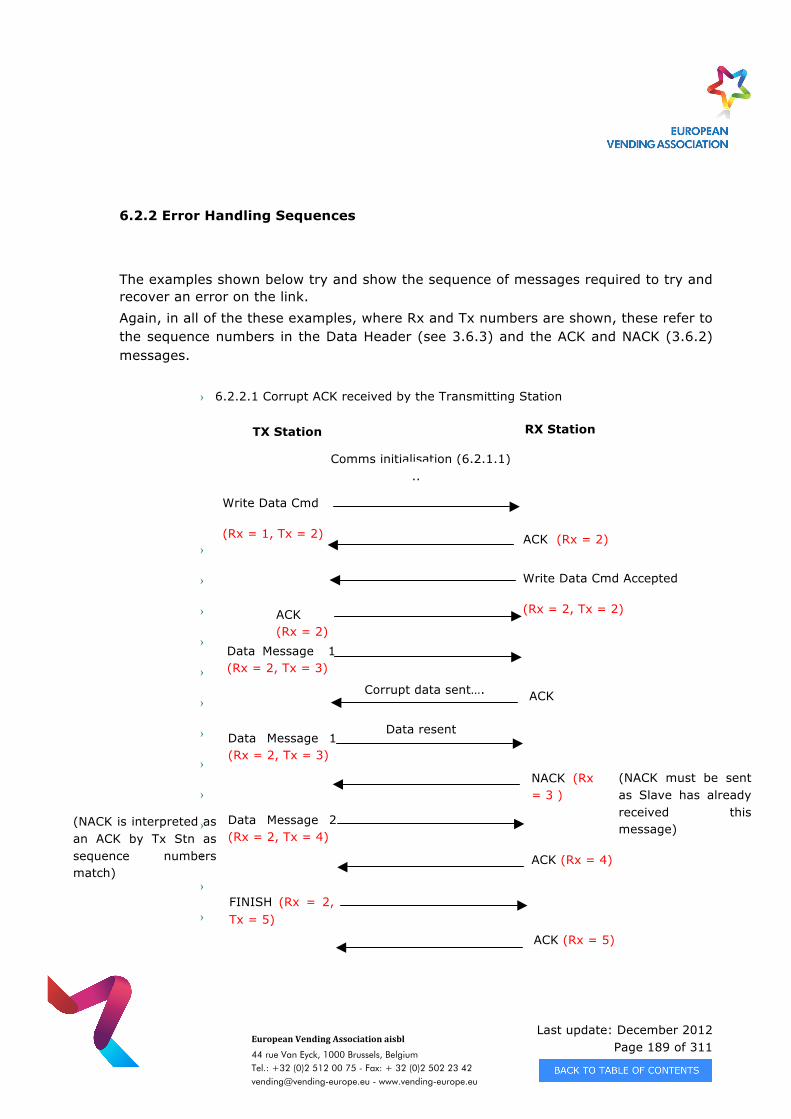
Last update: December 2012 Page 189 of 311
European Vending Association aisbl
44 rue Van Eyck, 1000 Brussels, Belgium Tel.: +32 (0)2 512 00 75 - Fax: + 32 (0)2 502 23 42 [email protected] - www.vending-europe.eu
6.2.2 Error Handling Sequences
The examples shown below try and show the sequence of messages required to try and recover an error on the link. Again, in all of the these examples, where Rx and Tx numbers are shown, these refer to the sequence numbers in the Data Header (see 3.6.3) and the ACK and NACK (3.6.2) messages.
› 6.2.2.1 Corrupt ACK received by the Transmitting Station
›
›
›
›
›
›
›
›
›
›
›
›
›
Comms initialisation (6.2.1.1) ..
..
TX Station RX Station
Write Data Cmd
(Rx = 1, Tx = 2) ACK (Rx = 2)
Data Message 1 (Rx = 2, Tx = 3)
ACK
(Rx = 3 )
Corrupt data sent….
Data resent
FINISH (Rx = 2, Tx = 5)
ACK (Rx = 5)
(NACK must be sent as Slave has already received this message)
ACK (Rx = 4)
Data Message 1 (Rx = 2, Tx = 3)
Data Message 2 (Rx = 2, Tx = 4)
NACK (Rx = 3 )
Write Data Cmd Accepted
(Rx = 2, Tx = 2) ACK (Rx = 2)
(NACK is interpreted as an ACK by Tx Stn as sequence numbers match)
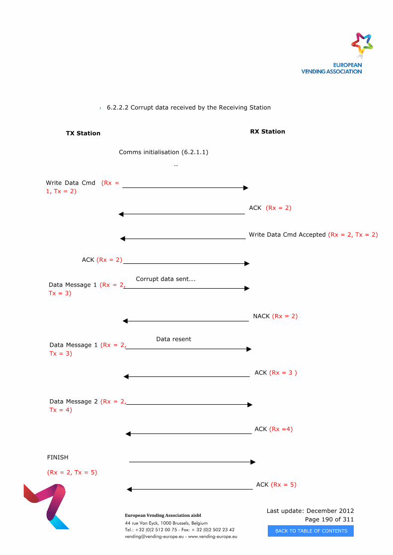
Last update: December 2012 Page 190 of 311
European Vending Association aisbl
44 rue Van Eyck, 1000 Brussels, Belgium Tel.: +32 (0)2 512 00 75 - Fax: + 32 (0)2 502 23 42 [email protected] - www.vending-europe.eu
› 6.2.2.2 Corrupt data received by the Receiving Station
Comms initialisation (6.2.1.1)
..
..
TX Station RX Station
Write Data Cmd (Rx = 1, Tx = 2)
ACK (Rx = 2)
Data Message 1 (Rx = 2, Tx = 3)
NACK (Rx = 2)
Corrupt data sent….
Data resent
FINISH
(Rx = 2, Tx = 5)
ACK (Rx = 5)
ACK (Rx =4)
Data Message 1 (Rx = 2, Tx = 3)
Data Message 2 (Rx = 2, Tx = 4)
ACK (Rx = 3 )
Write Data Cmd Accepted (Rx = 2, Tx = 2)
ACK (Rx = 2)
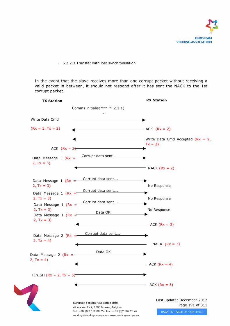
Last update: December 2012 Page 191 of 311
European Vending Association aisbl
44 rue Van Eyck, 1000 Brussels, Belgium Tel.: +32 (0)2 512 00 75 - Fax: + 32 (0)2 502 23 42 [email protected] - www.vending-europe.eu
› 6.2.2.3 Transfer with lost synchronisation
In the event that the slave receives more than one corrupt packet without receiving a valid packet in between, it should not respond after it has sent the NACK to the 1st corrupt packet.
Comms initialisation (6.2.1.1) ..
..
TX Station RX Station
Write Data Cmd
(Rx = 1, Tx = 2) ACK (Rx = 2)
Data Message 1 (Rx = 2, Tx = 3)
NACK (Rx = 2)
Corrupt data sent….
FINISH (Rx = 2, Tx = 5)
ACK (Rx = 5)
ACK (Rx = 3)
Data Message 1 (Rx = 2, Tx = 3)
Data Message 1 (Rx = 2, Tx = 3)
Write Data Cmd Accepted (Rx = 2, Tx = 2)
ACK (Rx = 2)
Corrupt data sent….
Data Message 1 (Rx = 2, Tx = 3)
No Response
Data Message 1 (Rx = 2, Tx = 3)
No Response Corrupt data sent….
Corrupt data sent….
Data OK
Data Message 2 (Rx = 2, Tx = 4)
ACK (Rx = 4)
Data Message 2 (Rx = 2, Tx = 4)
Corrupt data sent….
Data OK
No Response
NACK (Rx = 3)
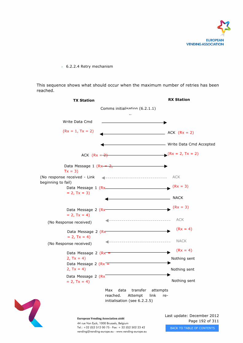
Last update: December 2012 Page 192 of 311
European Vending Association aisbl
44 rue Van Eyck, 1000 Brussels, Belgium Tel.: +32 (0)2 512 00 75 - Fax: + 32 (0)2 502 23 42 [email protected] - www.vending-europe.eu
› 6.2.2.4 Retry mechanism
This sequence shows what should occur when the maximum number of retries has been reached.
Comms initialisation (6.2.1.1) ..
..
TX Station RX Station
Write Data Cmd
(Rx = 1, Tx = 2) ACK (Rx = 2)
Data Message 1 (Rx = 2, Tx = 3)
Data Message 1 (Rx = 2, Tx = 3)
Data Message 2 (Rx = 2, Tx = 4)
Write Data Cmd Accepted
(Rx = 2, Tx = 2) ACK (Rx = 2)
Data Message 2 (Rx = 2, Tx = 4)
Data Message 2 (Rx = 2, Tx = 4)
(No Response received)
(No response received - Link beginning to fail)
NACK
(Rx = 3)
Nothing sent Data Message 2 (Rx = 2, Tx = 4)
Data Message 2 (Rx = 2, Tx = 4)
Nothing sent
Nothing sent
Max data transfer attempts reached. Attempt link re-initialisation (see 6.2.2.5)
ACK
(Rx = 3)
ACK
(Rx = 4)
NACK
(Rx = 4)
(No Response received)
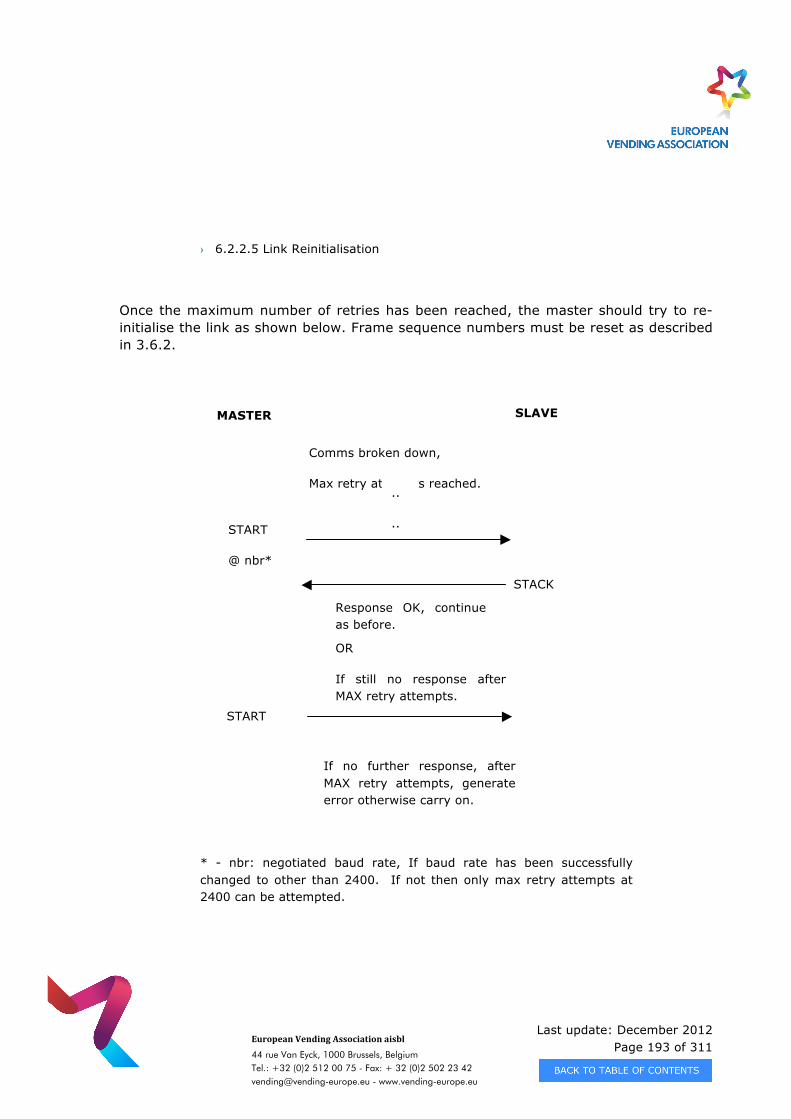
Last update: December 2012 Page 193 of 311
European Vending Association aisbl
44 rue Van Eyck, 1000 Brussels, Belgium Tel.: +32 (0)2 512 00 75 - Fax: + 32 (0)2 502 23 42 [email protected] - www.vending-europe.eu
› 6.2.2.5 Link Reinitialisation
Once the maximum number of retries has been reached, the master should try to re-initialise the link as shown below. Frame sequence numbers must be reset as described in 3.6.2.
Comms broken down,
Max retry attempts reached. ..
..
..
MASTER SLAVE
START
@ nbr*
STACK
Response OK, continue as before.
OR
If still no response after MAX retry attempts.
START
@ 2400 If no further response, after MAX retry attempts, generate error otherwise carry on.
* - nbr: negotiated baud rate, If baud rate has been successfully changed to other than 2400. If not then only max retry attempts at 2400 can be attempted.
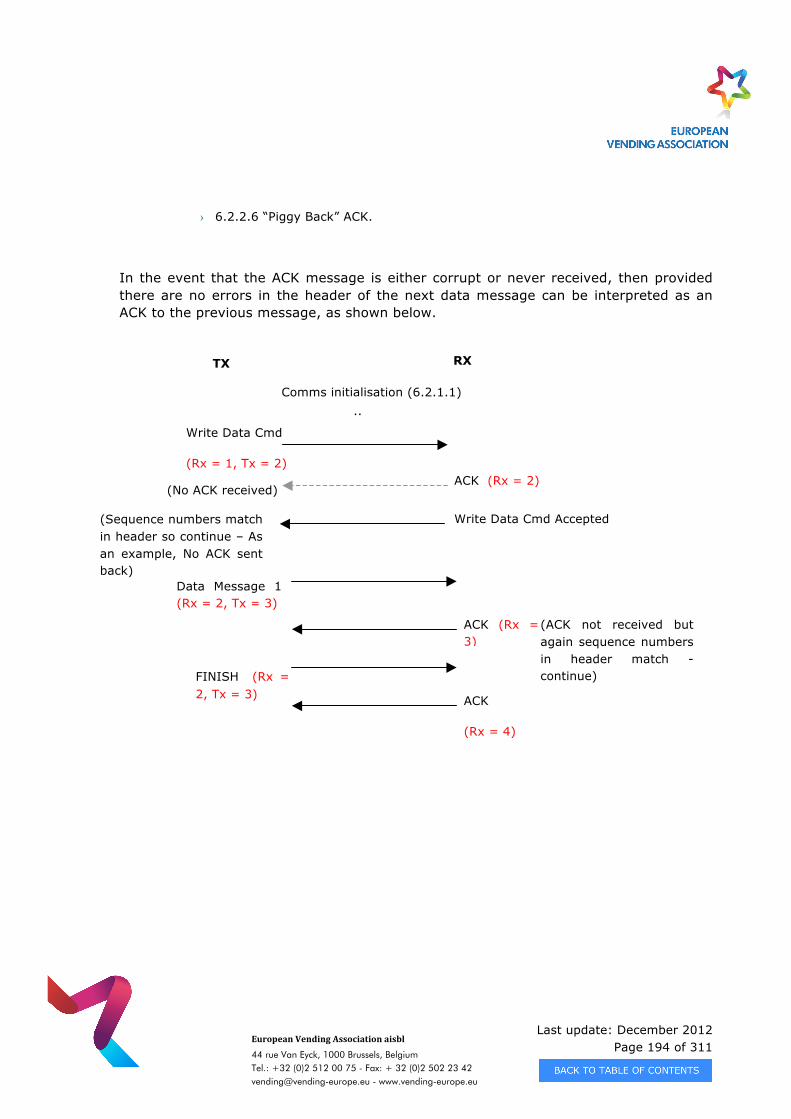
Last update: December 2012 Page 194 of 311
European Vending Association aisbl
44 rue Van Eyck, 1000 Brussels, Belgium Tel.: +32 (0)2 512 00 75 - Fax: + 32 (0)2 502 23 42 [email protected] - www.vending-europe.eu
› 6.2.2.6 “Piggy Back” ACK.
In the event that the ACK message is either corrupt or never received, then provided there are no errors in the header of the next data message can be interpreted as an ACK to the previous message, as shown below.
Comms initialisation (6.2.1.1) ..
..
TX Station
RX Station
Write Data Cmd
(Rx = 1, Tx = 2) ACK (Rx = 2)
Data Message 1 (Rx = 2, Tx = 3)
FINISH (Rx = 2, Tx = 3)
Write Data Cmd Accepted
(Rx = 2, Tx = 2)
(Sequence numbers match in header so continue – As an example, No ACK sent back)
ACK
(Rx = 4)
ACK (Rx = 3)
(No ACK received)
(ACK not received but again sequence numbers in header match - continue)
Last update: December 2012 Page 195 of 311
European Vending Association aisbl
44 rue Van Eyck, 1000 Brussels, Belgium Tel.: +32 (0)2 512 00 75 - Fax: + 32 (0)2 502 23 42 [email protected] - www.vending-europe.eu
CHAPTER 7 - DATA TRANSFER PHYSICAL LAYERS
7.1 SCOPE
This specification defines physical layers used for the interchange of data between two units in the vending environment. The actual eDDCMP and DEX/UCS protocols are specified in previous chapters of the EVA-DTS.
7.2 Overview The medium for the vending audit or configuration data transfer is currently based on two physical interfaces.
· Direct connected hardwire · IrDA based optics
Throughout this chapter reference will be made to three specific types of electronic devices as defined below: Vending Machine Device (VMD) - refers to the actual device in the vending
machine that monitors the various transactions and assimilates the audit data. Examples of targets are vending machine control boards, coin mechanisms, cashless readers, audit devices, etc.
Data Carrier (DC) - refers to the actual device that interrogates or configures the
VMD. Examples are hand held terminals, portable computers, radio telemetry systems, cellular systems, etc.
Business System Computer (BSC) - refers to the higher level computer system
that the DCs upload with their collected data from the VMD or receive configuration/setup information. Examples are mainframes, minis, personal computers, etc.
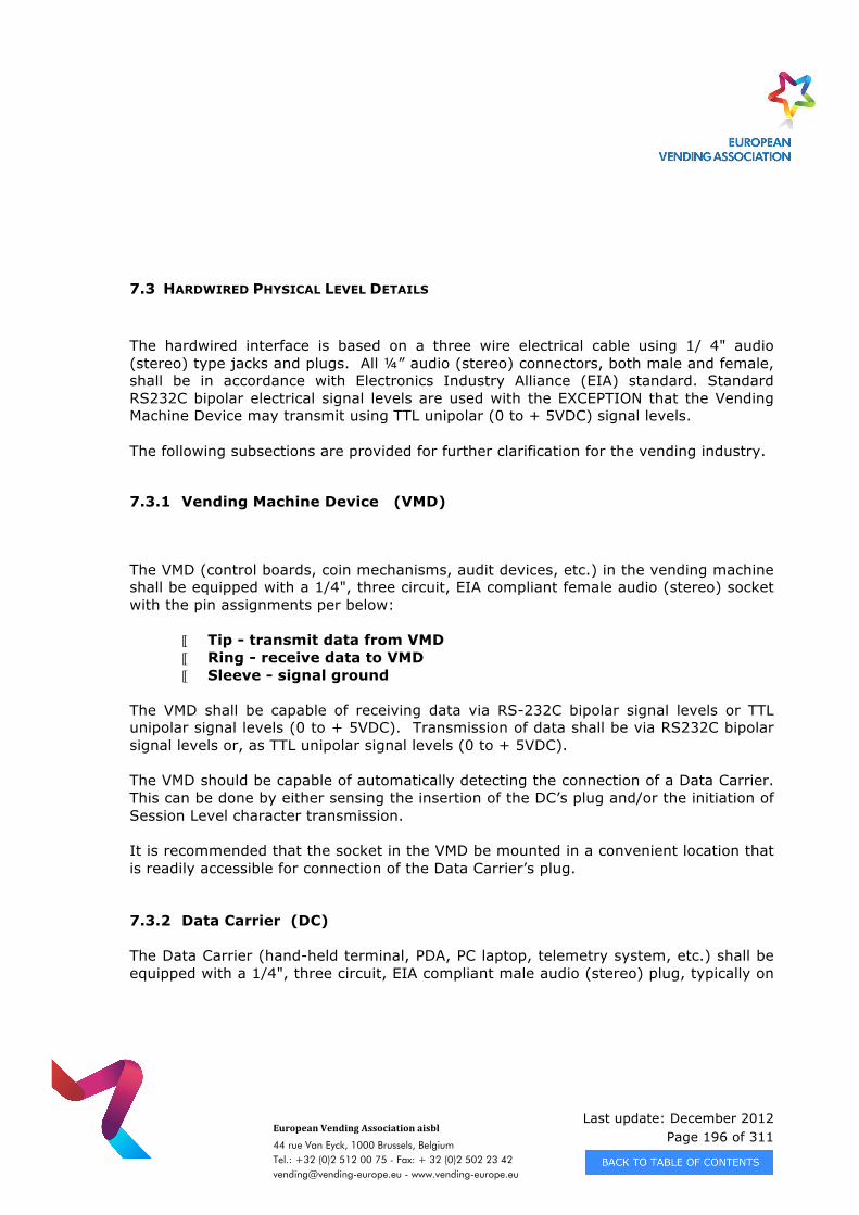
Last update: December 2012 Page 196 of 311
European Vending Association aisbl
44 rue Van Eyck, 1000 Brussels, Belgium Tel.: +32 (0)2 512 00 75 - Fax: + 32 (0)2 502 23 42 [email protected] - www.vending-europe.eu
7.3 HARDWIRED PHYSICAL LEVEL DETAILS
The hardwired interface is based on a three wire electrical cable using 1/ 4" audio (stereo) type jacks and plugs. All ¼” audio (stereo) connectors, both male and female, shall be in accordance with Electronics Industry Alliance (EIA) standard. Standard RS232C bipolar electrical signal levels are used with the EXCEPTION that the Vending Machine Device may transmit using TTL unipolar (0 to + 5VDC) signal levels. The following subsections are provided for further clarification for the vending industry.
7.3.1 Vending Machine Device (VMD)
The VMD (control boards, coin mechanisms, audit devices, etc.) in the vending machine shall be equipped with a 1/4", three circuit, EIA compliant female audio (stereo) socket with the pin assignments per below:
Tip - transmit data from VMD Ring - receive data to VMD Sleeve - signal ground
The VMD shall be capable of receiving data via RS-232C bipolar signal levels or TTL unipolar signal levels (0 to + 5VDC). Transmission of data shall be via RS232C bipolar signal levels or, as TTL unipolar signal levels (0 to + 5VDC). The VMD should be capable of automatically detecting the connection of a Data Carrier. This can be done by either sensing the insertion of the DC’s plug and/or the initiation of Session Level character transmission. It is recommended that the socket in the VMD be mounted in a convenient location that is readily accessible for connection of the Data Carrier’s plug.
7.3.2 Data Carrier (DC)
The Data Carrier (hand-held terminal, PDA, PC laptop, telemetry system, etc.) shall be equipped with a 1/4", three circuit, EIA compliant male audio (stereo) plug, typically on
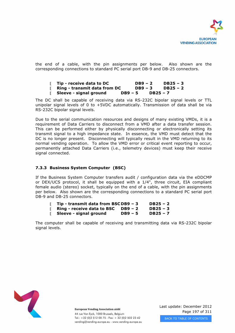
Last update: December 2012 Page 197 of 311
European Vending Association aisbl
44 rue Van Eyck, 1000 Brussels, Belgium Tel.: +32 (0)2 512 00 75 - Fax: + 32 (0)2 502 23 42 [email protected] - www.vending-europe.eu
the end of a cable, with the pin assignments per below. Also shown are the corresponding connections to standard PC serial port DB-9 and DB-25 connectors.
Tip - receive data to DC DB9 – 2 DB25 – 3 Ring - transmit data from DC DB9 – 3 DB25 – 2 Sleeve - signal ground DB9 – 5 DB25 – 7
The DC shall be capable of receiving data via RS-232C bipolar signal levels or TTL unipolar signal levels of 0 to +5VDC automatically. Transmission of data shall be via RS-232C bipolar signal levels. Due to the serial communication resources and designs of many existing VMDs, it is a requirement of Data Carriers to disconnect from a VMD after a data transfer session. This can be performed either by physically disconnecting or electronically setting its transmit signal to a high impedance state. In essence, the VMD must detect that the DC is no longer present. Disconnecting will typically result in the VMD returning to its normal vending operation. To allow the VMD error or critical event reporting to occur, permanently attached Data Carriers (i.e., telemetry devices) must keep their receive signal connected. 7.3.3 Business System Computer (BSC)
If the Business System Computer transfers audit / configuration data via the eDDCMP or DEX/UCS protocol, it shall be equipped with a 1/4", three circuit, EIA compliant female audio (stereo) socket, typically on the end of a cable, with the pin assignments per below. Also shown are the corresponding connections to a standard PC serial port DB-9 and DB-25 connectors.
Tip - transmit data from BSC DB9 – 3 DB25 – 2 Ring - receive data to BSC DB9 – 2 DB25 – 3 Sleeve - signal ground DB9 – 5 DB25 – 7
The computer shall be capable of receiving and transmitting data via RS-232C bipolar signal levels.
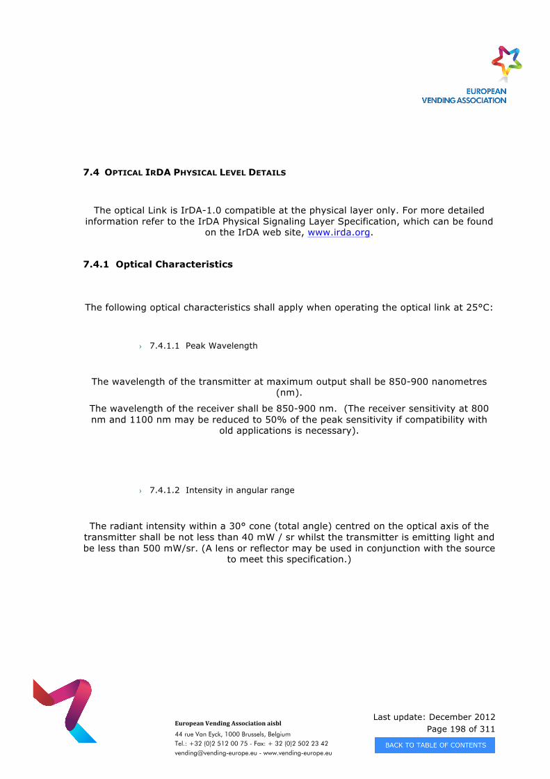
Last update: December 2012 Page 198 of 311
European Vending Association aisbl
44 rue Van Eyck, 1000 Brussels, Belgium Tel.: +32 (0)2 512 00 75 - Fax: + 32 (0)2 502 23 42 [email protected] - www.vending-europe.eu
7.4 OPTICAL IRDA PHYSICAL LEVEL DETAILS
The optical Link is IrDA-1.0 compatible at the physical layer only. For more detailed information refer to the IrDA Physical Signaling Layer Specification, which can be found
on the IrDA web site, www.irda.org.
7.4.1 Optical Characteristics
The following optical characteristics shall apply when operating the optical link at 25°C:
› 7.4.1.1 Peak Wavelength
The wavelength of the transmitter at maximum output shall be 850-900 nanometres (nm).
The wavelength of the receiver shall be 850-900 nm. (The receiver sensitivity at 800 nm and 1100 nm may be reduced to 50% of the peak sensitivity if compatibility with
old applications is necessary).
› 7.4.1.2 Intensity in angular range
The radiant intensity within a 30° cone (total angle) centred on the optical axis of the transmitter shall be not less than 40 mW / sr whilst the transmitter is emitting light and be less than 500 mW/sr. (A lens or reflector may be used in conjunction with the source
to meet this specification.)
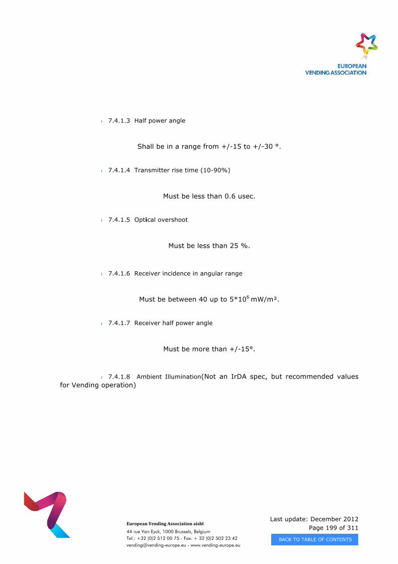
Last update: December 2012 Page 199 of 311
European Vending Association aisbl
44 rue Van Eyck, 1000 Brussels, Belgium Tel.: +32 (0)2 512 00 75 - Fax: + 32 (0)2 502 23 42 [email protected] - www.vending-europe.eu
› 7.4.1.3 Half power angle
Shall be in a range from +/-15 to +/-30 °.
› 7.4.1.4 Transmitter rise time (10-90%)
Must be less than 0.6 usec.
› 7.4.1.5 Optical overshoot
Must be less than 25 %.
› 7.4.1.6 Receiver incidence in angular range
Must be between 40 up to 5*106 mW/m².
› 7.4.1.7 Receiver half power angle
Must be more than +/-15°.
› 7.4.1.8 Ambient Illumination(Not an IrDA spec, but recommended values for Vending operation)
Last update: December 2012 Page 200 of 311
European Vending Association aisbl
44 rue Van Eyck, 1000 Brussels, Belgium Tel.: +32 (0)2 512 00 75 - Fax: + 32 (0)2 502 23 42 [email protected] - www.vending-europe.eu
The optical link shall operate in accordance with this specification when subjected to one of the following ambient illuminations:
Open shade ambient light environment.
This shall be a solar radiation which may reach 1000 watts per square metre integrated over the band 800 to 1000 nanometres.
The realistic maximum value will be 500 watts per square metre.
Indoors Illumination 50/100 Hz, 60/120 Hz.
This shall be fluorescent illumination of less than 100 watts per square metre integrated over the band 800 to 1000 nanometres.
› 7.4.1.9 Optical Filtering (not in IrDA spec)
It is permitted to use an infra red optical filter to improve the transmission characteristics of the link.
› 7.4.1.10 Optical Modulation
The modulation of the optical signal shall be as follows:
Modulation method: Send one optical pulse for a logical ‘1’ signal and no optical pulses for a logical ‘0’.
Modulation description: according to IrDA (1.41us or 3/16 baud rate)
Pulse Width at 9600 baud:1.41 us up to 22.12 us (which is 3/16 of baud rate time)
Pulse Width at 115,200 baud:1.41 us up to 2.71 us (which is 3/16 of baud rate time)
7.4.2 Receiver Characteristics
The maximum distance over which data can be transmitted is 1m.
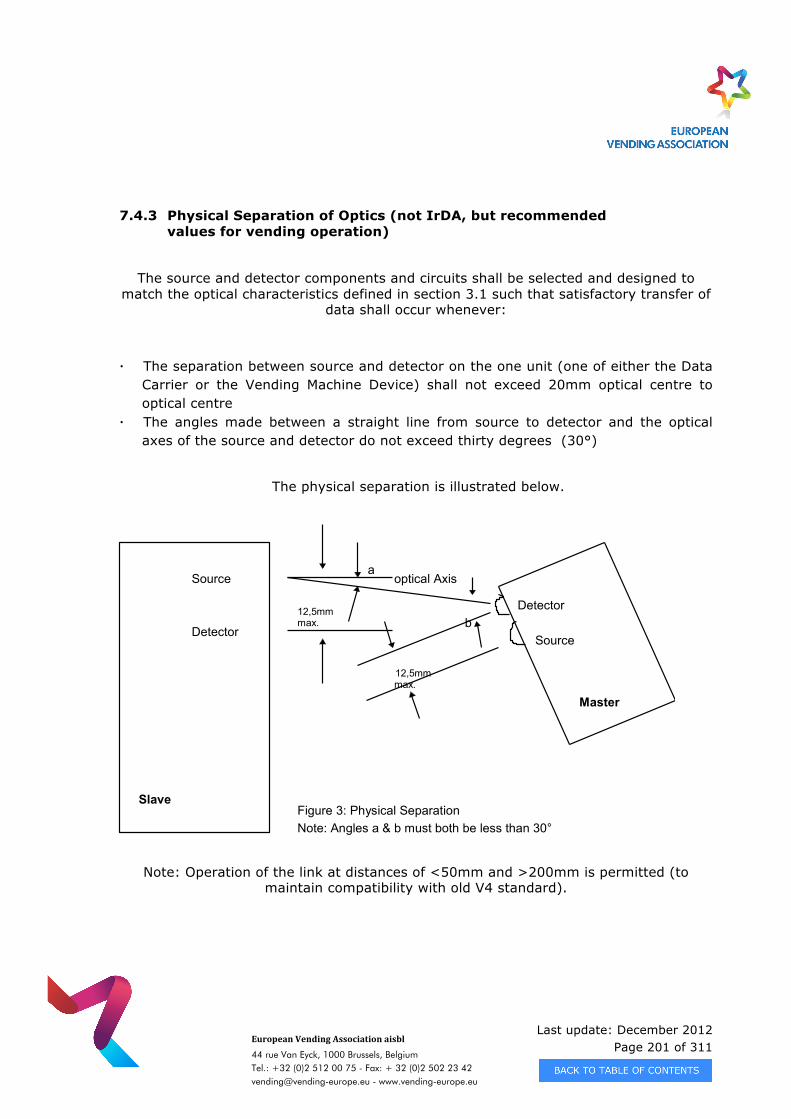
Last update: December 2012 Page 201 of 311
European Vending Association aisbl
44 rue Van Eyck, 1000 Brussels, Belgium Tel.: +32 (0)2 512 00 75 - Fax: + 32 (0)2 502 23 42 [email protected] - www.vending-europe.eu
7.4.3 Physical Separation of Optics (not IrDA, but recommended values for vending operation)
The source and detector components and circuits shall be selected and designed to match the optical characteristics defined in section 3.1 such that satisfactory transfer of
data shall occur whenever:
· The separation between source and detector on the one unit (one of either the Data Carrier or the Vending Machine Device) shall not exceed 20mm optical centre to optical centre
· The angles made between a straight line from source to detector and the optical axes of the source and detector do not exceed thirty degrees (30°)
The physical separation is illustrated below.
Note: Operation of the link at distances of <50mm and >200mm is permitted (to maintain compatibility with old V4 standard).
a
12,5mmmax.
12,5mmmax.
b
Slave
Master
Source
Detector
Detector
Source
optical Axis
Figure 3: Physical SeparationLimitsNote: Angles a & b must both be less than 30°
Last update: December 2012 Page 202 of 311
European Vending Association aisbl
44 rue Van Eyck, 1000 Brussels, Belgium Tel.: +32 (0)2 512 00 75 - Fax: + 32 (0)2 502 23 42 [email protected] - www.vending-europe.eu
APPENDIX A - DATA DICTIONARY
A.1 DEFINITIONS
Product Value:
The Product Value is the price stored in the PA102 for a specific product. Product Value is the amount recorded for a Paid Vend, a Free Vend, or a Test Vend.
Total Product Value Delivered = value of all Paid Vends + value of all Free Vends +value of all Test Vends
Payment Source:
Source of a value made available in payment for a Vend. Payment sources are Cash, Cashless, a Vend Token, or a Value Token.
Vend:
A vend is the delivery of a product and must be reported as only one of these types per occurrence: a Test Vend, a Free Vend, or a Paid Vend.
Complete Accountability of Paid Sales:
Payment (value) collected from all payment sources =
(Cash sales + Cash with Surcharges + Cash Overpays – Cash with Discounts – Cash credited from vending machine to coin mechanism)
Last update: December 2012 Page 203 of 311
European Vending Association aisbl
44 rue Van Eyck, 1000 Brussels, Belgium Tel.: +32 (0)2 512 00 75 - Fax: + 32 (0)2 502 23 42 [email protected] - www.vending-europe.eu
+ (Cashless 1 sales + Cashless 1 with Surcharges + Cashless 1 Overpays –
Cashless 1 with Discounts)
+ (Cashless 2 sales + Cashless 2 with Surcharges + Cashless 2 Overpays –
Cashless 2 with Discounts)
+ (ValueToken sales + Value Token with Surcharges + ValueToken Overpays –
ValueToken with Discounts)
+ (VendToken sales)
Note: May need to include Negative Sales for recycle / deposit machines.
Free Vend:
A free vend is a vend made without reference to a price list and is initiated by a special function e.g. VMC mode, PIN, or free vend card , key, coin (not a Free Vend Token) that controls a “Free Vend Mode”. A vend at a price of zero is only considered to be a free vend if it was initiated by a special function. Discounts, Surcharges and Overpay cannot apply to a Free Vend. The vend of a product with a price of 0 or a Vend Token is a paid vend.
Test Vend:
A test vend is a vend initiated by a special function (e.g. switch or VMC mode) for the purpose of testing the function of the vending machine. Cash, tokens, cashless credit, discounts, surcharges, etc., may be used in the performance of a Test Vend. however the sales and vend fields associated with these payment methods apply to a Paid Vend only and are not altered. Likewise, no Free Vend fields are altered due to a Test Vend.
Paid Vend:
A paid vend is a vend made with reference to a price, even if the set price is zero. Note that the Product Value is reported regardless of the final adjusted selling price.
Last update: December 2012 Page 204 of 311
European Vending Association aisbl
44 rue Van Eyck, 1000 Brussels, Belgium Tel.: +32 (0)2 512 00 75 - Fax: + 32 (0)2 502 23 42 [email protected] - www.vending-europe.eu
Cash Vend:
A Cash Vend is a Paid Vend that requires the collection of coin or currency to complete the vend. Discounts (including 100% discounts), Surcharges, and Overpays can apply to Cash Vends. Cash Vends do not include Cashless Vend.
Cashless Vend:
A Cashless Vend is a Paid Vend which requires the interaction of a cashless device to complete the vend. Discounts (including 100% discounts), Surcharges, and Overpays can apply to Cashless Vends.
Vend Token Vend:
A Vend Token Vend is a Paid Vend that requires acceptance of a Vend Token (or Coupon) from a monetary device. It is immaterial if the Vend Token is returned at the conclusion of the Vend. The acceptance of one Vend Token is sufficient to complete one, and only one, vend. Surcharges, Overpays, and Discounts cannot apply since a Vend Token Vend is performed without reference to price. A Vend Token Vend is not reported as a Cash Vend, a Cashless Vend, nor a Value Token Vend.
Value Token Vend:
A Value Token Vend is a Paid Vend that requires acceptance of a Value Token (or Coupon). A Value Token may be used in combination with other payment sources (used as a partial payment in combination with cash or cashless value). A Value Token does not have cash value and change is not returned from the value attributed to a Value Token. It is immaterial if the Value Token is returned at the conclusion of the Vend. Discounts, Surcharges and Overpays may apply to pure Value Token Vends.
Mixed Payment Vend:
A Vend with payment contributed from more than one payment source. This is a Paid Vend with data being reported in 2 or more of the following payment categories: Cash, Cashless, and/or Value Token. The product value will be split and placed in the “Value of Sales” field for the participating payment types based on their respective contribution. The number of vends/sales data fields are incremented for each payment device which has participated in the vend. Discounts and Surcharges can be applied from/to more than one payment source during a single vend. A Vend Token Vend cannot be a Mixed Payment Vend since a Vend Token is worth one complete product vend.
Last update: December 2012 Page 205 of 311
European Vending Association aisbl
44 rue Van Eyck, 1000 Brussels, Belgium Tel.: +32 (0)2 512 00 75 - Fax: + 32 (0)2 502 23 42 [email protected] - www.vending-europe.eu
Discount:
A discount is the value not collected due to special pricing. A discount can be given by the VMD and both of the cashless devices. Discounts could apply to Cash, both Cashless devices and a Value Token in the same vend. In such a case, the discount value attributed to each payment source is the value recorded for that source and only that source. A Discount may be applied to a Value Token Vend but not to a Free Vend Token Vend.
Surcharge:
A surcharge is an additional value collected due to special pricing and is a intended event. A surcharge can be given by the VMD and both of the cashless devices. Surcharges could apply to Cash, both Cashless devices and a Value Token in the same vend. In such a case, the surcharge value attributed to each payment source is the value recorded for that source and only that source. A Surcharge may be applied to a Value Token Vend but not to a Free Token Vend.
Note: A Surcharge is a planned upward price adjustment as opposed to an Overpay which is an accidental retention of more value than is necessary for the vend. An Overpay is generally caused by a low change condition in the coin mechanism.
Overpay:
Overpay is an additional value collected, and no longer available for vending, that is not specifically a surcharge. An Overpay is an unintended event as opposed to a Surcharge. It is generally due to a low change condition in the coin mechanism not allowing all the customers change to be paid back, or from a non-refundable cashless system after a failed vend. Overpays cannot apply to Vend Token Vends.
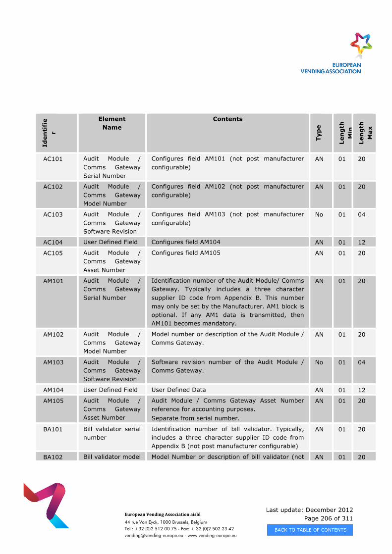
Last update: December 2012 Page 206 of 311
European Vending Association aisbl
44 rue Van Eyck, 1000 Brussels, Belgium Tel.: +32 (0)2 512 00 75 - Fax: + 32 (0)2 502 23 42 [email protected] - www.vending-europe.eu
Iden
tifi
er
Element Name
Contents
Typ
e
Len
gth
M
in
Len
gth
M
ax
AC101 Audit Module / Comms Gateway Serial Number
Configures field AM101 (not post manufacturer configurable)
AN 01 20
AC102 Audit Module / Comms Gateway Model Number
Configures field AM102 (not post manufacturer configurable)
AN 01 20
AC103 Audit Module / Comms Gateway Software Revision
Configures field AM103 (not post manufacturer configurable)
No 01 04
AC104 User Defined Field Configures field AM104 AN 01 12
AC105 Audit Module / Comms Gateway Asset Number
Configures field AM105 AN 01 20
AM101 Audit Module / Comms Gateway Serial Number
Identification number of the Audit Module/ Comms Gateway. Typically includes a three character supplier ID code from Appendix B. This number may only be set by the Manufacturer. AM1 block is optional. If any AM1 data is transmitted, then AM101 becomes mandatory.
AN 01 20
AM102 Audit Module / Comms Gateway Model Number
Model number or description of the Audit Module / Comms Gateway.
AN 01 20
AM103 Audit Module / Comms Gateway Software Revision
Software revision number of the Audit Module / Comms Gateway.
No 01 04
AM104 User Defined Field User Defined Data AN 01 12
AM105 Audit Module / Comms Gateway Asset Number
Audit Module / Comms Gateway Asset Number reference for accounting purposes. Separate from serial number.
AN 01 20
BA101 Bill validator serial number
Identification number of bill validator. Typically, includes a three character supplier ID code from Appendix B (not post manufacturer configurable)
AN 01 20
BA102 Bill validator model Model Number or description of bill validator (not AN 01 20
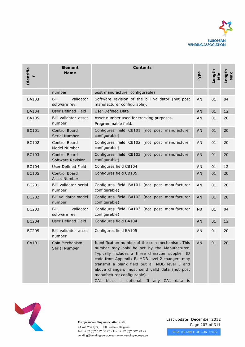
Last update: December 2012 Page 207 of 311
European Vending Association aisbl
44 rue Van Eyck, 1000 Brussels, Belgium Tel.: +32 (0)2 512 00 75 - Fax: + 32 (0)2 502 23 42 [email protected] - www.vending-europe.eu
Iden
tifi
er
Element Name
Contents
Typ
e
Len
gth
M
in
Len
gth
M
ax
number post manufacturer configurable)
BA103 Bill validator software rev.
Software revision of the bill validator (not post manufacturer configurable).
AN 01 04
BA104 User Defined Field User Defined Data AN 01 12
BA105 Bill validator asset number
Asset number used for tracking purposes. Programmable field.
AN 01 20
BC101 Control Board Serial Number
Configures field CB101 (not post manufacturer configurable)
AN 01 20
BC102 Control Board Model Number
Configures field CB102 (not post manufacturer configurable)
AN 01 20
BC103 Control Board Software Revision
Configures field CB103 (not post manufacturer configurable)
AN 01 20
BC104 User Defined Field Configures field CB104 AN 01 12
BC105 Control Board Asset Number
Configures field CB105 AN 01 20
BC201 Bill validator serial number
Configures field BA101 (not post manufacturer configurable)
AN 01 20
BC202 Bill validator model number
Configures field BA102 (not post manufacturer configurable)
AN 01 20
BC203 Bill validator software rev.
Configures field BA103 (not post manufacturer configurable)
N0 01 04
BC204 User Defined Field Configures field BA104 AN 01 12
BC205 Bill validator asset number
Configures field BA105 AN 01 20
CA101 Coin Mechanism Serial Number
Identification number of the coin mechanism. This number may only be set by the Manufacturer. Typically includes a three character supplier ID code from Appendix B. MDB level 2 changers may transmit a blank field but all MDB level 3 and above changers must send valid data (not post manufacturer configurable). CA1 block is optional. If any CA1 data is
AN 01 20
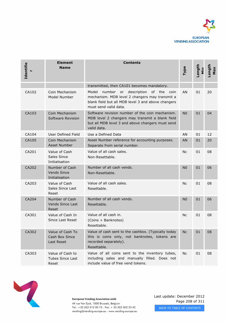
Last update: December 2012 Page 208 of 311
European Vending Association aisbl
44 rue Van Eyck, 1000 Brussels, Belgium Tel.: +32 (0)2 512 00 75 - Fax: + 32 (0)2 502 23 42 [email protected] - www.vending-europe.eu
Iden
tifi
er
Element Name
Contents
Typ
e
Len
gth
M
in
Len
gth
M
ax
transmitted, then CA101 becomes mandatory.
CA102 Coin Mechanism Model Number
Model number or description of the coin mechanism. MDB level 2 changers may transmit a blank field but all MDB level 3 and above changers must send valid data.
AN 01 20
CA103 Coin Mechanism Software Revision
Software revision number of the coin mechanism. MDB level 2 changers may transmit a blank field but all MDB level 3 and above changers must send valid data.
N0 01 04
CA104 User Defined Field Use a Defined Data AN 01 12
CA105 Coin Mechanism Asset Number
Asset Number reference for accounting purposes. Separate from serial number.
AN 01 20
CA201 Value of Cash Sales Since Initialisation
Value of all cash sales. Non-Resettable.
Nc 01 08
CA202 Number of Cash Vends Since Initialisation
Number of all cash vends. Non-Resettable.
N0 01 06
CA203 Value of Cash Sales Since Last Reset
Value of all cash sales. Resettable.
Nc 01 08
CA204 Number of Cash Vends Since Last Reset
Number of all cash vends. Resettable.
N0 01 06
CA301 Value of Cash In Since Last Reset
Value of all cash in. (Coins + Banknotes) Resettable.
Nc 01 08
CA302 Value of Cash To Cash Box Since Last Reset
Value of cash sent to the cashbox. (Typically today this is coins only, not banknotes, tokens are recorded separately). Resettable.
Nc 01 08
CA303 Value of Cash to Tubes Since Last Reset
Value of all coins sent to the inventory tubes, including sales and manually filled. Does not include value of free vend tokens.
Nc 01 08
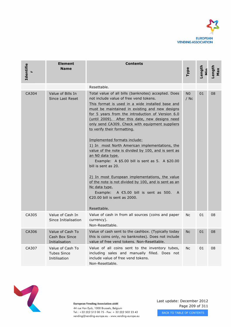
Last update: December 2012 Page 209 of 311
European Vending Association aisbl
44 rue Van Eyck, 1000 Brussels, Belgium Tel.: +32 (0)2 512 00 75 - Fax: + 32 (0)2 502 23 42 [email protected] - www.vending-europe.eu
Iden
tifi
er
Element Name
Contents
Typ
e
Len
gth
M
in
Len
gth
M
ax
Resettable.
CA304 Value of Bills In Since Last Reset
Total value of all bills (banknotes) accepted. Does not include value of free vend tokens. This format is used in a wide installed base and must be maintained in existing and new designs for 5 years from the introduction of Version 6.0 (until 2009). After this date, new designs need only send CA309. Check with equipment suppliers to verify their formatting. Implemented formats include: 1) In most North American implementations, the value of the note is divided by 100, and is sent as an N0 data type. Example: A $5.00 bill is sent as 5. A $20.00 bill is sent as 20. 2) In most European implementations, the value of the note is not divided by 100, and is sent as an Nc data type. Example: A €5.00 bill is sent as 500. A €20.00 bill is sent as 2000. Resettable.
N0 / Nc
01 08
CA305 Value of Cash In Since Initialisation
Value of cash in from all sources (coins and paper currency). Non-Resettable.
Nc 01 08
CA306 Value of Cash To Cash Box Since Initialisation
Value of cash sent to the cashbox. (Typically today this is coins only, no banknotes). Does not include value of free vend tokens. Non-Resettable.
Nc 01 08
CA307 Value of Cash To Tubes Since Initilisation
Value of all coins sent to the inventory tubes, including sales and manually filled. Does not include value of free vend tokens. Non-Resettable.
Nc 01 08
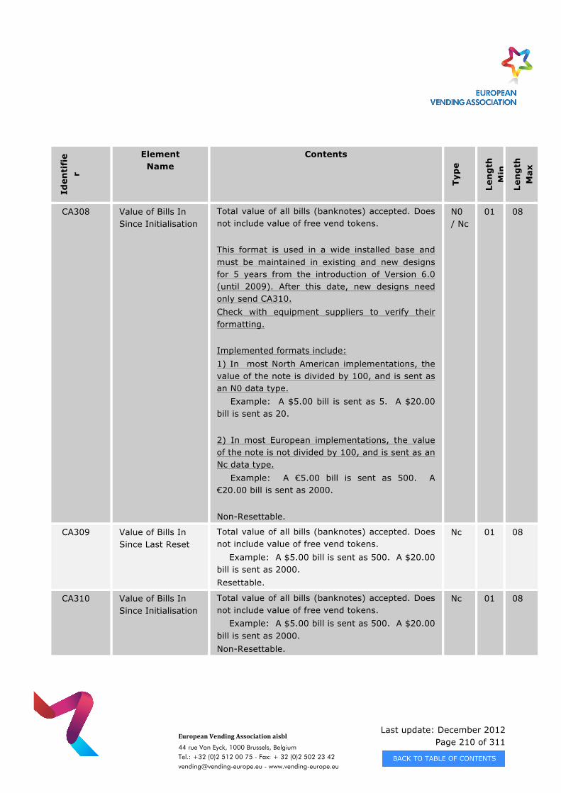
Last update: December 2012 Page 210 of 311
European Vending Association aisbl
44 rue Van Eyck, 1000 Brussels, Belgium Tel.: +32 (0)2 512 00 75 - Fax: + 32 (0)2 502 23 42 [email protected] - www.vending-europe.eu
Iden
tifi
er
Element Name
Contents
Typ
e
Len
gth
M
in
Len
gth
M
ax
CA308 Value of Bills In Since Initialisation
Total value of all bills (banknotes) accepted. Does not include value of free vend tokens. This format is used in a wide installed base and must be maintained in existing and new designs for 5 years from the introduction of Version 6.0 (until 2009). After this date, new designs need only send CA310. Check with equipment suppliers to verify their formatting. Implemented formats include: 1) In most North American implementations, the value of the note is divided by 100, and is sent as an N0 data type. Example: A $5.00 bill is sent as 5. A $20.00 bill is sent as 20. 2) In most European implementations, the value of the note is not divided by 100, and is sent as an Nc data type. Example: A €5.00 bill is sent as 500. A €20.00 bill is sent as 2000. Non-Resettable.
N0 / Nc
01 08
CA309 Value of Bills In Since Last Reset
Total value of all bills (banknotes) accepted. Does not include value of free vend tokens. Example: A $5.00 bill is sent as 500. A $20.00 bill is sent as 2000. Resettable.
Nc 01 08
CA310 Value of Bills In Since Initialisation
Total value of all bills (banknotes) accepted. Does not include value of free vend tokens. Example: A $5.00 bill is sent as 500. A $20.00 bill is sent as 2000. Non-Resettable.
Nc 01 08
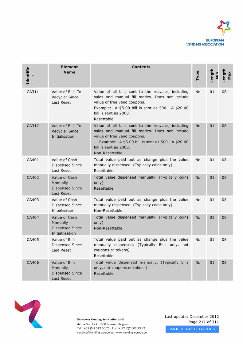
Last update: December 2012 Page 211 of 311
European Vending Association aisbl
44 rue Van Eyck, 1000 Brussels, Belgium Tel.: +32 (0)2 512 00 75 - Fax: + 32 (0)2 502 23 42 [email protected] - www.vending-europe.eu
Iden
tifi
er
Element Name
Contents
Typ
e
Len
gth
M
in
Len
gth
M
ax
CA311 Value of Bills To Recycler Since Last Reset
Value of all bills sent to the recycler, including sales and manual fill modes. Does not include value of free vend coupons. Example: A $5.00 bill is sent as 500. A $20.00 bill is sent as 2000. Resettable.
Nc 01 08
CA312 Value of Bills To Recycler Since Initialisation
Value of all bills sent to the recycler, including sales and manual fill modes. Does not include value of free vend coupons. Example: A $5.00 bill is sent as 500. A $20.00 bill is sent as 2000. Non-Resettable.
Nc 01 08
CA401 Value of Cash Dispensed Since Last Reset
Total value paid out as change plus the value manually dispensed. (Typically coins only). Resettable.
Nc 01 08
CA402 Value of Cash Manually Dispensed Since Last Reset
Total value dispensed manually. (Typically coins only) Resettable.
Nc 01 08
CA403 Value of Cash Dispensed Since Initialisation
Total value paid out as change plus the value manually dispensed. (Typically coins only). Non-Resettable.
Nc 01 08
CA404 Value of Cash Manually Dispensed Since Initiatlisation
Total value dispensed manually. (Typically coins only) Non-Resettable.
Nc 01 08
CA405 Value of Bills Dispensed Since Last Reset
Total value paid out as change plus the value manually dispensed. (Typically Bills only, not coupons or tokens). Resettable.
Nc 01 08
CA406 Value of Bills Manually Dispensed Since Last Reset
Total value dispensed manually. (Typically bills only, not coupons or tokens) Resettable.
Nc 01 08
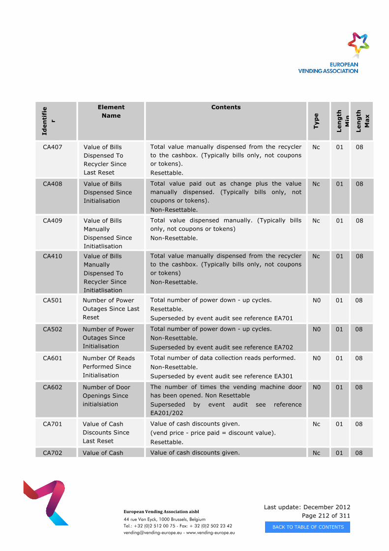
Last update: December 2012 Page 212 of 311
European Vending Association aisbl
44 rue Van Eyck, 1000 Brussels, Belgium Tel.: +32 (0)2 512 00 75 - Fax: + 32 (0)2 502 23 42 [email protected] - www.vending-europe.eu
Iden
tifi
er
Element Name
Contents
Typ
e
Len
gth
M
in
Len
gth
M
ax
CA407 Value of Bills Dispensed To Recycler Since Last Reset
Total value manually dispensed from the recycler to the cashbox. (Typically bills only, not coupons or tokens). Resettable.
Nc 01 08
CA408 Value of Bills Dispensed Since Initialisation
Total value paid out as change plus the value manually dispensed. (Typically bills only, not coupons or tokens). Non-Resettable.
Nc 01 08
CA409 Value of Bills Manually Dispensed Since Initiatlisation
Total value dispensed manually. (Typically bills only, not coupons or tokens) Non-Resettable.
Nc 01 08
CA410 Value of Bills Manually Dispensed To Recycler Since Initiatlisation
Total value manually dispensed from the recycler to the cashbox. (Typically bills only, not coupons or tokens) Non-Resettable.
Nc 01 08
CA501 Number of Power Outages Since Last Reset
Total number of power down - up cycles. Resettable. Superseded by event audit see reference EA701
N0 01 08
CA502 Number of Power Outages Since Initialisation
Total number of power down - up cycles. Non-Resettable. Superseded by event audit see reference EA702
N0 01 08
CA601 Number Of Reads Performed Since Initialisation
Total number of data collection reads performed. Non-Resettable. Superseded by event audit see reference EA301
N0 01 08
CA602 Number of Door Openings Since initialsiation
The number of times the vending machine door has been opened. Non Resettable Superseded by event audit see reference EA201/202
N0 01 08
CA701 Value of Cash Discounts Since Last Reset
Value of cash discounts given. (vend price - price paid = discount value). Resettable.
Nc 01 08
CA702 Value of Cash Value of cash discounts given. Nc 01 08
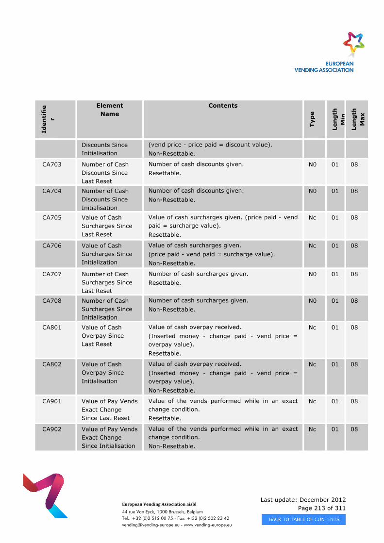
Last update: December 2012 Page 213 of 311
European Vending Association aisbl
44 rue Van Eyck, 1000 Brussels, Belgium Tel.: +32 (0)2 512 00 75 - Fax: + 32 (0)2 502 23 42 [email protected] - www.vending-europe.eu
Iden
tifi
er
Element Name
Contents
Typ
e
Len
gth
M
in
Len
gth
M
ax
Discounts Since Initialisation
(vend price - price paid = discount value). Non-Resettable.
CA703 Number of Cash Discounts Since Last Reset
Number of cash discounts given. Resettable.
N0 01 08
CA704 Number of Cash Discounts Since Initialisation
Number of cash discounts given. Non-Resettable.
N0 01 08
CA705 Value of Cash Surcharges Since Last Reset
Value of cash surcharges given. (price paid - vend paid = surcharge value). Resettable.
Nc 01 08
CA706 Value of Cash Surcharges Since Initialization
Value of cash surcharges given. (price paid - vend paid = surcharge value). Non-Resettable.
Nc 01 08
CA707 Number of Cash Surcharges Since Last Reset
Number of cash surcharges given. Resettable.
N0 01 08
CA708 Number of Cash Surcharges Since Initialisation
Number of cash surcharges given. Non-Resettable.
N0 01 08
CA801 Value of Cash Overpay Since Last Reset
Value of cash overpay received. (Inserted money - change paid - vend price = overpay value). Resettable.
Nc 01 08
CA802 Value of Cash Overpay Since Initialisation
Value of cash overpay received. (Inserted money - change paid - vend price = overpay value). Non-Resettable.
Nc 01 08
CA901 Value of Pay Vends Exact Change Since Last Reset
Value of the vends performed while in an exact change condition. Resettable.
Nc 01 08
CA902 Value of Pay Vends Exact Change Since Initialisation
Value of the vends performed while in an exact change condition. Non-Resettable.
Nc 01 08
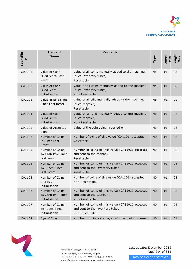
Last update: December 2012 Page 214 of 311
European Vending Association aisbl
44 rue Van Eyck, 1000 Brussels, Belgium Tel.: +32 (0)2 512 00 75 - Fax: + 32 (0)2 502 23 42 [email protected] - www.vending-europe.eu
Iden
tifi
er
Element Name
Contents
Typ
e
Len
gth
M
in
Len
gth
M
ax
CA1001 Value of Cash Filled Since Last Reset
Value of all coins manually added to the machine. (filled inventory tubes) Resettable.
Nc 01 08
CA1002 Value of Cash Filled Since Initialisation
Value of all coins manually added to the machine. (filled inventory tubes) Non-Resettable.
Nc 01 08
CA1003 Value of Bills Filled Since Last Reset
Value of all bills manually added to the machine. (filled recycler) Resettable.
Nc 01 08
CA1004 Value of Cash Filled Since Initialisation
Value of all bills manually added to the machine. (filled recycler) Non-Resettable.
Nc 01 08
CA1101 Value of Accepted Coin
Value of the coin being reported on. Nc 01 08
CA1102 Number of Coins In Since Last Reset
Number of coins of this value (CA1101) accepted. Resettable.
N0 01 08
CA1103 Number of Coins To Cash Box Since Last Reset
Number of coins of this value (CA1101) accepted and sent to the cashbox. Resettable.
N0 01 08
CA1104 Number of Coins To Tubes Since Last Reset
Number of coins of this value (CA1101) accepted and sent to the inventory tubes Resettable.
N0 01 08
CA1105 Number of Coins In Since Initialisation
Number of coins of this value (CA1101) accepted. Non-Resettable.
N0 01 08
CA1106 Number of Coins To Cash Box Since Initialisation
Number of coins of this value (CA1101) accepted and sent to the cashbox. Non-Resettable.
N0 01 08
CA1107 Number of Coins To Tubes Since Initialisation
Number of coins of this value (CA1101) accepted and sent to the inventory tubes Non-Resettable.
N0 01 08
CA1108 Age of Coin Number to indicate age of the coin. Lowest N0 01 01
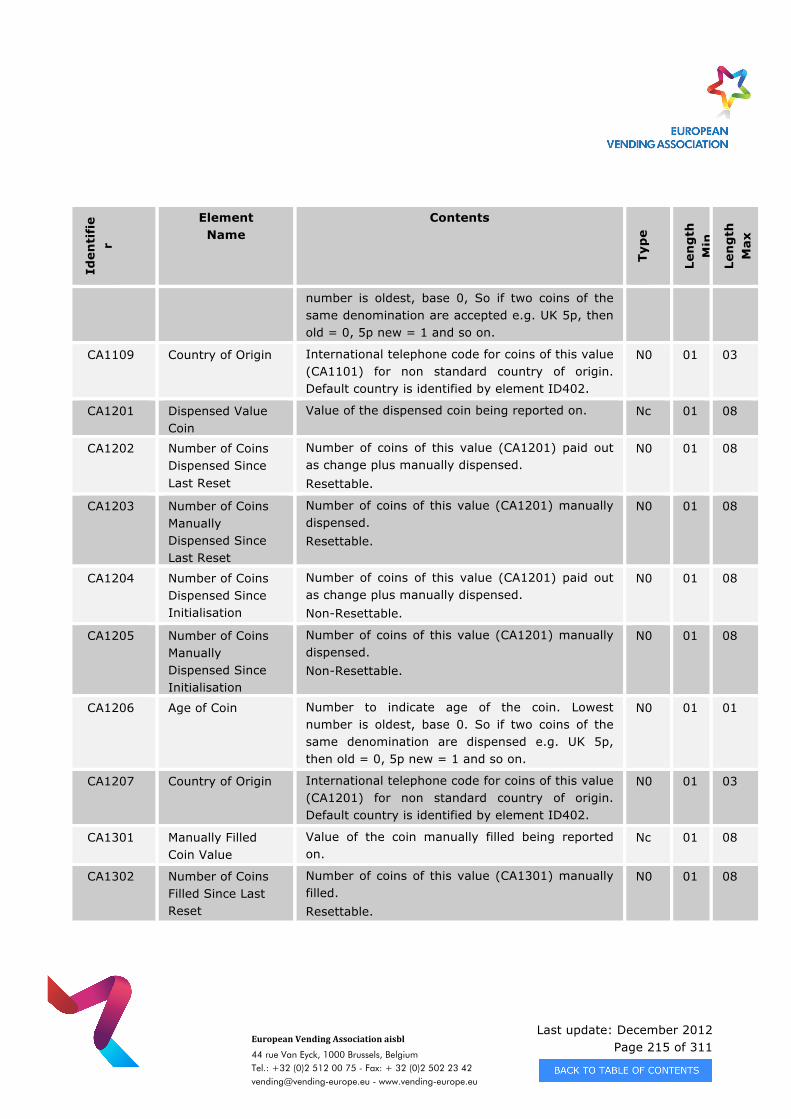
Last update: December 2012 Page 215 of 311
European Vending Association aisbl
44 rue Van Eyck, 1000 Brussels, Belgium Tel.: +32 (0)2 512 00 75 - Fax: + 32 (0)2 502 23 42 [email protected] - www.vending-europe.eu
Iden
tifi
er
Element Name
Contents
Typ
e
Len
gth
M
in
Len
gth
M
ax
number is oldest, base 0, So if two coins of the same denomination are accepted e.g. UK 5p, then old = 0, 5p new = 1 and so on.
CA1109 Country of Origin International telephone code for coins of this value (CA1101) for non standard country of origin. Default country is identified by element ID402.
N0 01 03
CA1201 Dispensed Value Coin
Value of the dispensed coin being reported on. Nc 01 08
CA1202 Number of Coins Dispensed Since Last Reset
Number of coins of this value (CA1201) paid out as change plus manually dispensed. Resettable.
N0 01 08
CA1203 Number of Coins Manually Dispensed Since Last Reset
Number of coins of this value (CA1201) manually dispensed. Resettable.
N0 01 08
CA1204 Number of Coins Dispensed Since Initialisation
Number of coins of this value (CA1201) paid out as change plus manually dispensed. Non-Resettable.
N0 01 08
CA1205 Number of Coins Manually Dispensed Since Initialisation
Number of coins of this value (CA1201) manually dispensed. Non-Resettable.
N0 01 08
CA1206 Age of Coin
Number to indicate age of the coin. Lowest number is oldest, base 0. So if two coins of the same denomination are dispensed e.g. UK 5p, then old = 0, 5p new = 1 and so on.
N0 01 01
CA1207 Country of Origin International telephone code for coins of this value (CA1201) for non standard country of origin. Default country is identified by element ID402.
N0 01 03
CA1301 Manually Filled Coin Value
Value of the coin manually filled being reported on.
Nc 01 08
CA1302 Number of Coins Filled Since Last Reset
Number of coins of this value (CA1301) manually filled. Resettable.
N0 01 08
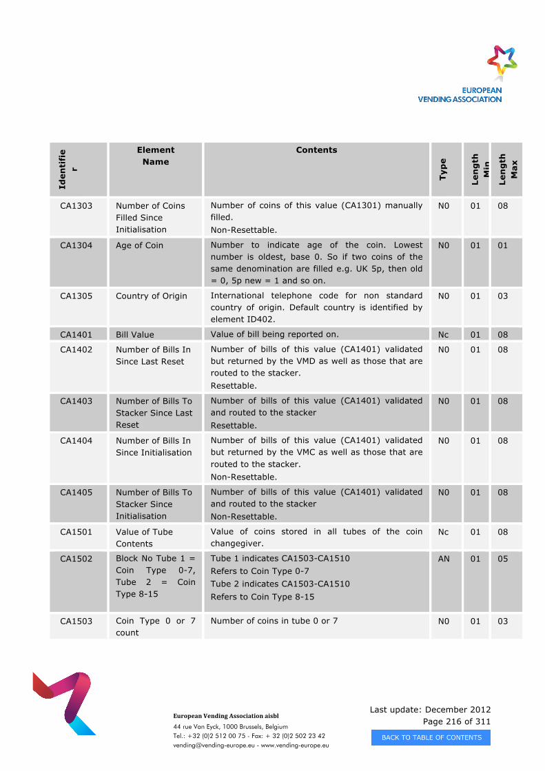
Last update: December 2012 Page 216 of 311
European Vending Association aisbl
44 rue Van Eyck, 1000 Brussels, Belgium Tel.: +32 (0)2 512 00 75 - Fax: + 32 (0)2 502 23 42 [email protected] - www.vending-europe.eu
Iden
tifi
er
Element Name
Contents
Typ
e
Len
gth
M
in
Len
gth
M
ax
CA1303 Number of Coins Filled Since Initialisation
Number of coins of this value (CA1301) manually filled. Non-Resettable.
N0 01 08
CA1304 Age of Coin Number to indicate age of the coin. Lowest number is oldest, base 0. So if two coins of the same denomination are filled e.g. UK 5p, then old = 0, 5p new = 1 and so on.
N0 01 01
CA1305 Country of Origin International telephone code for non standard country of origin. Default country is identified by element ID402.
N0 01 03
CA1401 Bill Value Value of bill being reported on. Nc 01 08
CA1402 Number of Bills In Since Last Reset
Number of bills of this value (CA1401) validated but returned by the VMD as well as those that are routed to the stacker. Resettable.
N0 01 08
CA1403 Number of Bills To Stacker Since Last Reset
Number of bills of this value (CA1401) validated and routed to the stacker Resettable.
N0 01 08
CA1404 Number of Bills In Since Initialisation
Number of bills of this value (CA1401) validated but returned by the VMC as well as those that are routed to the stacker. Non-Resettable.
N0 01 08
CA1405 Number of Bills To Stacker Since Initialisation
Number of bills of this value (CA1401) validated and routed to the stacker Non-Resettable.
N0 01 08
CA1501 Value of Tube Contents
Value of coins stored in all tubes of the coin changegiver.
Nc 01 08
CA1502 Block No Tube 1 = Coin Type 0-7, Tube 2 = Coin Type 8-15
Tube 1 indicates CA1503-CA1510 Refers to Coin Type 0-7 Tube 2 indicates CA1503-CA1510 Refers to Coin Type 8-15
AN 01 05
CA1503 Coin Type 0 or 7 count
Number of coins in tube 0 or 7 N0 01 03
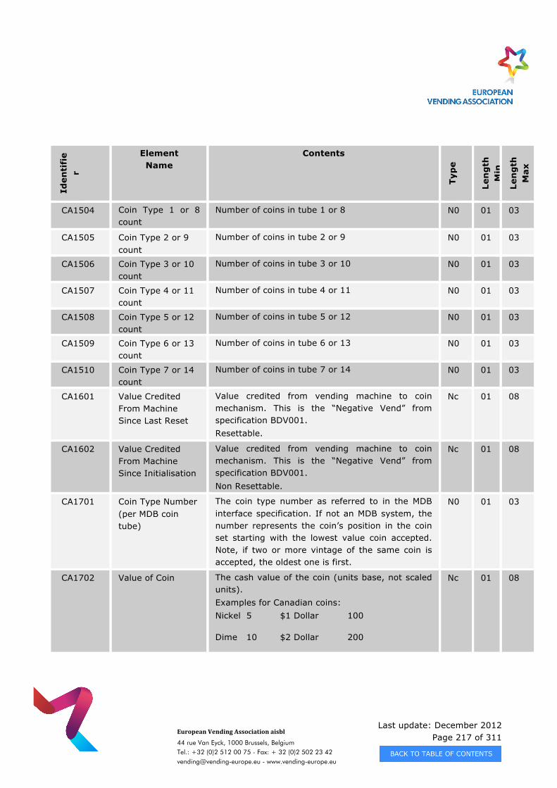
Last update: December 2012 Page 217 of 311
European Vending Association aisbl
44 rue Van Eyck, 1000 Brussels, Belgium Tel.: +32 (0)2 512 00 75 - Fax: + 32 (0)2 502 23 42 [email protected] - www.vending-europe.eu
Iden
tifi
er
Element Name
Contents
Typ
e
Len
gth
M
in
Len
gth
M
ax
CA1504 Coin Type 1 or 8 count
Number of coins in tube 1 or 8 N0 01 03
CA1505 Coin Type 2 or 9 count
Number of coins in tube 2 or 9 N0 01 03
CA1506 Coin Type 3 or 10 count
Number of coins in tube 3 or 10 N0 01 03
CA1507 Coin Type 4 or 11 count
Number of coins in tube 4 or 11 N0 01 03
CA1508 Coin Type 5 or 12 count
Number of coins in tube 5 or 12 N0 01 03
CA1509 Coin Type 6 or 13 count
Number of coins in tube 6 or 13 N0 01 03
CA1510 Coin Type 7 or 14 count
Number of coins in tube 7 or 14 N0 01 03
CA1601 Value Credited From Machine Since Last Reset
Value credited from vending machine to coin mechanism. This is the “Negative Vend” from specification BDV001. Resettable.
Nc 01 08
CA1602 Value Credited From Machine Since Initialisation
Value credited from vending machine to coin mechanism. This is the “Negative Vend” from specification BDV001. Non Resettable.
Nc 01 08
CA1701 Coin Type Number (per MDB coin tube)
The coin type number as referred to in the MDB interface specification. If not an MDB system, the number represents the coin’s position in the coin set starting with the lowest value coin accepted. Note, if two or more vintage of the same coin is accepted, the oldest one is first.
N0 01 03
CA1702 Value of Coin The cash value of the coin (units base, not scaled units). Examples for Canadian coins: Nickel 5 $1 Dollar 100
Dime 10 $2 Dollar 200
Nc 01 08
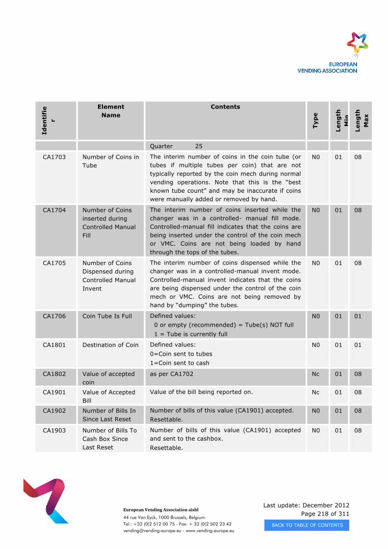
Last update: December 2012 Page 218 of 311
European Vending Association aisbl
44 rue Van Eyck, 1000 Brussels, Belgium Tel.: +32 (0)2 512 00 75 - Fax: + 32 (0)2 502 23 42 [email protected] - www.vending-europe.eu
Iden
tifi
er
Element Name
Contents
Typ
e
Len
gth
M
in
Len
gth
M
ax
Quarter 25
CA1703 Number of Coins in Tube
The interim number of coins in the coin tube (or tubes if multiple tubes per coin) that are not typically reported by the coin mech during normal vending operations. Note that this is the “best known tube count” and may be inaccurate if coins were manually added or removed by hand.
N0 01 08
CA1704 Number of Coins inserted during Controlled Manual Fill
The interim number of coins inserted while the changer was in a controlled- manual fill mode. Controlled-manual fill indicates that the coins are being inserted under the control of the coin mech or VMC. Coins are not being loaded by hand through the tops of the tubes.
N0 01 08
CA1705 Number of Coins Dispensed during Controlled Manual Invent
The interim number of coins dispensed while the changer was in a controlled-manual invent mode. Controlled-manual invent indicates that the coins are being dispensed under the control of the coin mech or VMC. Coins are not being removed by hand by “dumping” the tubes.
N0 01 08
CA1706 Coin Tube Is Full Defined values: 0 or empty (recommended) = Tube(s) NOT full 1 = Tube is currently full
N0 01 01
CA1801 Destination of Coin Defined values: 0=Coin sent to tubes 1=Coin sent to cash
N0 01 01
CA1802 Value of accepted coin
as per CA1702 Nc 01 08
CA1901 Value of Accepted Bill
Value of the bill being reported on. Nc 01 08
CA1902 Number of Bills In Since Last Reset
Number of bills of this value (CA1901) accepted. Resettable.
N0 01 08
CA1903 Number of Bills To Cash Box Since Last Reset
Number of bills of this value (CA1901) accepted and sent to the cashbox. Resettable.
N0 01 08
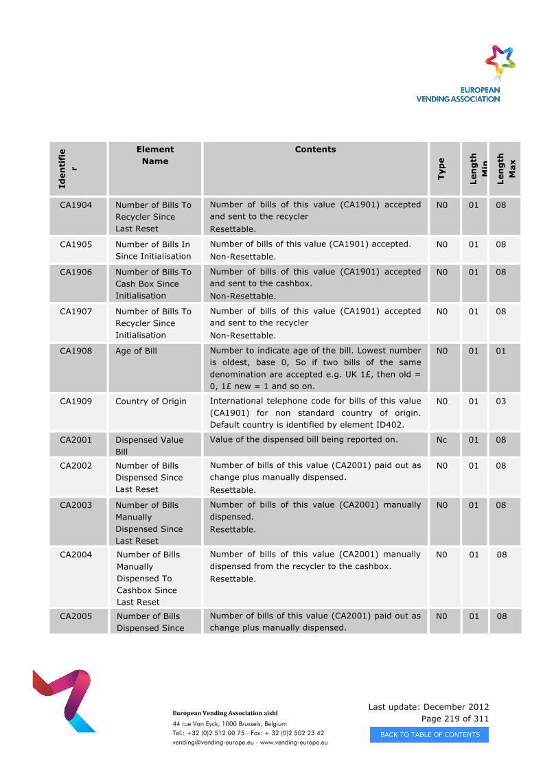
Last update: December 2012 Page 219 of 311
European Vending Association aisbl
44 rue Van Eyck, 1000 Brussels, Belgium Tel.: +32 (0)2 512 00 75 - Fax: + 32 (0)2 502 23 42 [email protected] - www.vending-europe.eu
Iden
tifi
er
Element Name
Contents
Typ
e
Len
gth
M
in
Len
gth
M
ax
CA1904 Number of Bills To Recycler Since Last Reset
Number of bills of this value (CA1901) accepted and sent to the recycler Resettable.
N0 01 08
CA1905 Number of Bills In Since Initialisation
Number of bills of this value (CA1901) accepted. Non-Resettable.
N0 01 08
CA1906 Number of Bills To Cash Box Since Initialisation
Number of bills of this value (CA1901) accepted and sent to the cashbox. Non-Resettable.
N0 01 08
CA1907 Number of Bills To Recycler Since Initialisation
Number of bills of this value (CA1901) accepted and sent to the recycler Non-Resettable.
N0 01 08
CA1908 Age of Bill Number to indicate age of the bill. Lowest number is oldest, base 0, So if two bills of the same denomination are accepted e.g. UK 1£, then old = 0, 1£ new = 1 and so on.
N0 01 01
CA1909 Country of Origin International telephone code for bills of this value (CA1901) for non standard country of origin. Default country is identified by element ID402.
N0 01 03
CA2001 Dispensed Value Bill
Value of the dispensed bill being reported on. Nc 01 08
CA2002 Number of Bills Dispensed Since Last Reset
Number of bills of this value (CA2001) paid out as change plus manually dispensed. Resettable.
N0 01 08
CA2003 Number of Bills Manually Dispensed Since Last Reset
Number of bills of this value (CA2001) manually dispensed. Resettable.
N0 01 08
CA2004 Number of Bills Manually Dispensed To Cashbox Since Last Reset
Number of bills of this value (CA2001) manually dispensed from the recycler to the cashbox. Resettable.
N0 01 08
CA2005 Number of Bills Dispensed Since
Number of bills of this value (CA2001) paid out as change plus manually dispensed.
N0 01 08
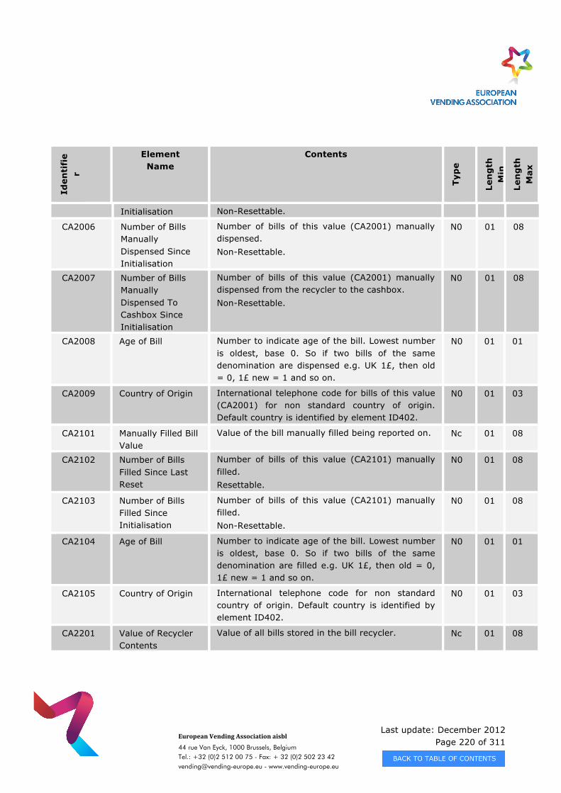
Last update: December 2012 Page 220 of 311
European Vending Association aisbl
44 rue Van Eyck, 1000 Brussels, Belgium Tel.: +32 (0)2 512 00 75 - Fax: + 32 (0)2 502 23 42 [email protected] - www.vending-europe.eu
Iden
tifi
er
Element Name
Contents
Typ
e
Len
gth
M
in
Len
gth
M
ax
Initialisation Non-Resettable.
CA2006 Number of Bills Manually Dispensed Since Initialisation
Number of bills of this value (CA2001) manually dispensed. Non-Resettable.
N0 01 08
CA2007 Number of Bills Manually Dispensed To Cashbox Since Initialisation
Number of bills of this value (CA2001) manually dispensed from the recycler to the cashbox. Non-Resettable.
N0 01 08
CA2008 Age of Bill
Number to indicate age of the bill. Lowest number is oldest, base 0. So if two bills of the same denomination are dispensed e.g. UK 1£, then old = 0, 1£ new = 1 and so on.
N0 01 01
CA2009 Country of Origin International telephone code for bills of this value (CA2001) for non standard country of origin. Default country is identified by element ID402.
N0 01 03
CA2101 Manually Filled Bill Value
Value of the bill manually filled being reported on. Nc 01 08
CA2102 Number of Bills Filled Since Last Reset
Number of bills of this value (CA2101) manually filled. Resettable.
N0 01 08
CA2103 Number of Bills Filled Since Initialisation
Number of bills of this value (CA2101) manually filled. Non-Resettable.
N0 01 08
CA2104 Age of Bill Number to indicate age of the bill. Lowest number is oldest, base 0. So if two bills of the same denomination are filled e.g. UK 1£, then old = 0, 1£ new = 1 and so on.
N0 01 01
CA2105 Country of Origin International telephone code for non standard country of origin. Default country is identified by element ID402.
N0 01 03
CA2201 Value of Recycler Contents
Value of all bills stored in the bill recycler. Nc 01 08
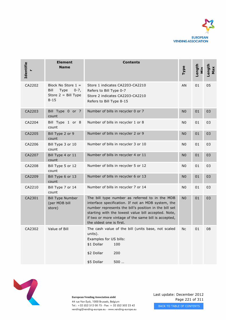
Last update: December 2012 Page 221 of 311
European Vending Association aisbl
44 rue Van Eyck, 1000 Brussels, Belgium Tel.: +32 (0)2 512 00 75 - Fax: + 32 (0)2 502 23 42 [email protected] - www.vending-europe.eu
Iden
tifi
er
Element Name
Contents
Typ
e
Len
gth
M
in
Len
gth
M
ax
CA2202 Block No Store 1 = Bill Type 0-7, Store 2 = Bill Type 8-15
Store 1 indicates CA2203-CA2210 Refers to Bill Type 0-7 Store 2 indicates CA2203-CA2210 Refers to Bill Type 8-15
AN 01 05
CA2203 Bill Type 0 or 7 count
Number of bills in recycler 0 or 7 N0 01 03
CA2204 Bill Type 1 or 8 count
Number of bills in recycler 1 or 8 N0 01 03
CA2205 Bill Type 2 or 9 count
Number of bills in recycler 2 or 9 N0 01 03
CA2206 Bill Type 3 or 10 count
Number of bills in recycler 3 or 10 N0 01 03
CA2207 Bill Type 4 or 11 count
Number of bills in recycler 4 or 11 N0 01 03
CA2208 Bill Type 5 or 12 count
Number of bills in recycler 5 or 12 N0 01 03
CA2209 Bill Type 6 or 13 count
Number of bills in recycler 6 or 13 N0 01 03
CA2210 Bill Type 7 or 14 count
Number of bills in recycler 7 or 14 N0 01 03
CA2301 Bill Type Number (per MDB bill store)
The bill type number as referred to in the MDB interface specification. If not an MDB system, the number represents the bill’s position in the bill set starting with the lowest value bill accepted. Note, if two or more vintage of the same bill is accepted, the oldest one is first.
N0 01 03
CA2302 Value of Bill The cash value of the bill (units base, not scaled units). Examples for US bills: $1 Dollar 100
$2 Dollar 200
$5 Dollar 500 …
Nc 01 08
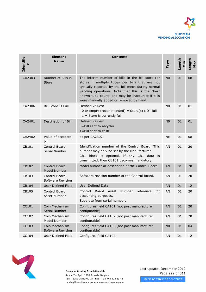
Last update: December 2012 Page 222 of 311
European Vending Association aisbl
44 rue Van Eyck, 1000 Brussels, Belgium Tel.: +32 (0)2 512 00 75 - Fax: + 32 (0)2 502 23 42 [email protected] - www.vending-europe.eu
Iden
tifi
er
Element Name
Contents
Typ
e
Len
gth
M
in
Len
gth
M
ax
CA2303 Number of Bills in Store
The interim number of bills in the bill store (or stores if multiple tubes per bill) that are not typically reported by the bill mech during normal vending operations. Note that this is the “best known tube count” and may be inaccurate if bills were manually added or removed by hand.
N0 01 08
CA2306 Bill Store Is Full Defined values: 0 or empty (recommended) = Store(s) NOT full 1 = Store is currently full
N0 01 01
CA2401 Destination of Bill Defined values: 0=Bill sent to recycler 1=Bill sent to cash
N0 01 01
CA2402 Value of accepted bill
as per CA2302 Nc 01 08
CB101 Control Board Serial Number
Identification number of the Control Board. This number may only be set by the Manufacturer. CB1 block is optional. If any CB1 data is transmitted, then CB101 becomes mandatory.
AN 01 20
CB102 Control Board Model Number
Model number or description of the Control Board. AN 01 20
CB103 Control Board Software Revision
Software revision number of the Control Board. AN 01 20
CB104 User Defined Field User Defined Data AN 01 12
CB105 Control Board Asset Number
Control Board Asset Number reference for accounting purposes. Separate from serial number.
AN 01 20
CC101 Coin Mechanism Serial Number
Configures field CA101 (not post manufacturer configurable)
AN 01 20
CC102 Coin Mechanism Model Number
Configures field CA102 (not post manufacturer configurable)
AN 01 20
CC103 Coin Mechanism Software Revision
Configures field CA103 (not post manufacturer configurable)
N0 01 04
CC104 User Defined Field Configures field CA104 AN 01 12
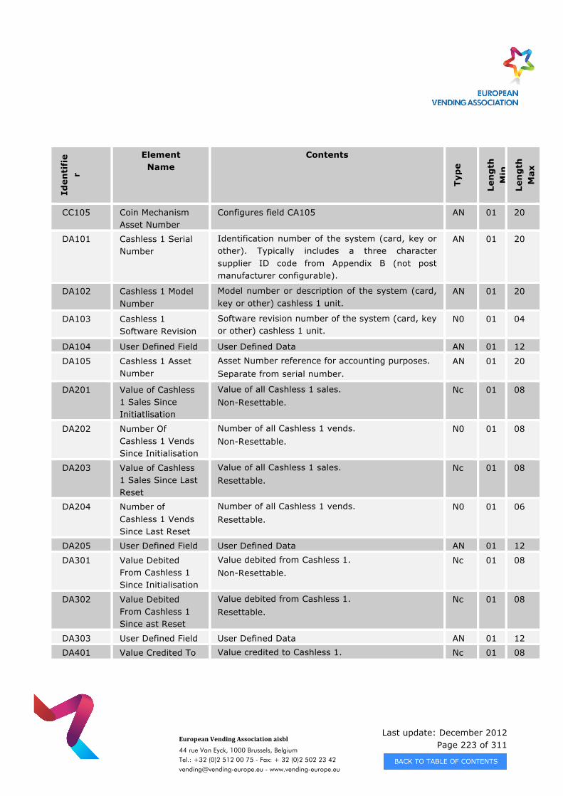
Last update: December 2012 Page 223 of 311
European Vending Association aisbl
44 rue Van Eyck, 1000 Brussels, Belgium Tel.: +32 (0)2 512 00 75 - Fax: + 32 (0)2 502 23 42 [email protected] - www.vending-europe.eu
Iden
tifi
er
Element Name
Contents
Typ
e
Len
gth
M
in
Len
gth
M
ax
CC105 Coin Mechanism Asset Number
Configures field CA105 AN 01 20
DA101 Cashless 1 Serial Number
Identification number of the system (card, key or other). Typically includes a three character supplier ID code from Appendix B (not post manufacturer configurable).
AN 01 20
DA102 Cashless 1 Model Number
Model number or description of the system (card, key or other) cashless 1 unit.
AN 01 20
DA103 Cashless 1 Software Revision
Software revision number of the system (card, key or other) cashless 1 unit.
N0 01 04
DA104 User Defined Field User Defined Data AN 01 12
DA105 Cashless 1 Asset Number
Asset Number reference for accounting purposes. Separate from serial number.
AN 01 20
DA201 Value of Cashless 1 Sales Since Initiatlisation
Value of all Cashless 1 sales. Non-Resettable.
Nc 01 08
DA202 Number Of Cashless 1 Vends Since Initialisation
Number of all Cashless 1 vends. Non-Resettable.
N0 01 08
DA203 Value of Cashless 1 Sales Since Last Reset
Value of all Cashless 1 sales. Resettable.
Nc 01 08
DA204 Number of Cashless 1 Vends Since Last Reset
Number of all Cashless 1 vends. Resettable.
N0 01 06
DA205 User Defined Field User Defined Data AN 01 12
DA301 Value Debited From Cashless 1 Since Initialisation
Value debited from Cashless 1. Non-Resettable.
Nc 01 08
DA302 Value Debited From Cashless 1 Since ast Reset
Value debited from Cashless 1. Resettable.
Nc 01 08
DA303 User Defined Field User Defined Data AN 01 12
DA401 Value Credited To Value credited to Cashless 1. Nc 01 08
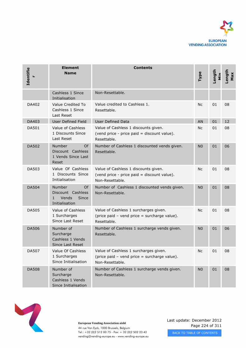
Last update: December 2012 Page 224 of 311
European Vending Association aisbl
44 rue Van Eyck, 1000 Brussels, Belgium Tel.: +32 (0)2 512 00 75 - Fax: + 32 (0)2 502 23 42 [email protected] - www.vending-europe.eu
Iden
tifi
er
Element Name
Contents
Typ
e
Len
gth
M
in
Len
gth
M
ax
Cashless 1 Since Initialisation
Non-Resettable.
DA402 Value Credited To Cashless 1 Since Last Reset
Value credited to Cashless 1. Resettable.
Nc 01 08
DA403 User Defined Field User Defined Data AN 01 12
DA501 Value of Cashless 1 Discounts Since Last Reset
Value of Cashless 1 discounts given. (vend price - price paid = discount value). Resettable.
Nc 01 08
DA502 Number Of Discount Cashless 1 Vends Since Last Reset
Number of Cashless 1 discounted vends given. Resettable.
N0 01 06
DA503 Value Of Cashless 1 Discounts Since Initialisation
Value of Cashless 1 discounts given. (vend price - price paid = discount value). Non-Resettable.
Nc 01 08
DA504 Number Of Discount Cashless 1 Vends Since Initialisation
Number of Cashless 1 discounted vends given. Non-Resettable.
N0 01 08
DA505 Value of Cashless 1 Surcharges Since Last Reset
Value of Cashless 1 surcharges given. (price paid – vend price = surcharge value). Resettable.
Nc 01 08
DA506 Number of Surcharge Cashless 1 Vends Since Last Reset
Number of Cashless 1 surcharge vends given. Resettable.
N0 01 06
DA507 Value Of Cashless 1 Surcharges Since Initialisation
Value of Cashless 1 surcharges given. (price paid – vend price = surcharge value). Non-Resettable.
Nc 01 08
DA508 Number of Surcharge Cashless 1 Vends Since Initialisation
Number of Cashless 1 surcharge vends given. Non-Resettable.
N0 01 08

Last update: December 2012 Page 225 of 311
European Vending Association aisbl
44 rue Van Eyck, 1000 Brussels, Belgium Tel.: +32 (0)2 512 00 75 - Fax: + 32 (0)2 502 23 42 [email protected] - www.vending-europe.eu
Iden
tifi
er
Element Name
Contents
Typ
e
Len
gth
M
in
Len
gth
M
ax
DA601 Revaluation Incentive on Cashless 1 Since Initialisation
The value of the additional money added to Cashless 1 as an incentive. E.g. $10 cash input, $11 credited to card, Incentive is $1 Non-Resettable
Nc 01 08
DA602 Revaluation Incentive on Cashless 1 Since Last Reset
The value of the additional money added to Cashless 1 as an incentive. E.g. $10 cash input, $11 credited to card, Incentive is $1 Resettable.
Nc 01 08
DA701 Cashless 1 User Group Number
Cashless 1 User group being reported on. N0 01 13
DA702 Cashless 1 User Group Net Sales since last reset.
Net sale (equal to the value deducted from the cards) of the user group in DA701 Resettable.
Nc 01 08
DA703 User Group Value Added To Cashless 1 since last reset
Revaluation and Initialisation (equal to the value added to the cards) of the user group in DA701 Resettable.
Nc 01 08
DA704 Cashless 1 User Group Discounts since last reset
Discount deducted from the standard prices (showing up the net sale prices) of the user group in DA701. Resettable.
Nc 01 08
DA705 Number of products sold to Cashless 1 user group since initialisation
This is the number of paid vends from all payment sources of the user group in DA701 since initialisation. Non-resettable.
N0 01 08
DA706 Number of products sold to Cashless 1 user group since last reset
This is the number of paid vends from all payment sources of the user group in DA701 since last reset. Resettable.
N0 01 06
DA707 Cashless 1 User Group Net Sales since initialization
Net sale (equal to the value deducted from the cards) of the user group in DA701 Non-resettable.
Nc 01 08
DA708 User Group Value Revaluation and Initialisation (equal to the value Nc 01 08
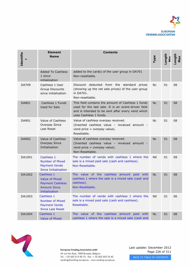
Last update: December 2012 Page 226 of 311
European Vending Association aisbl
44 rue Van Eyck, 1000 Brussels, Belgium Tel.: +32 (0)2 512 00 75 - Fax: + 32 (0)2 502 23 42 [email protected] - www.vending-europe.eu
Iden
tifi
er
Element Name
Contents
Typ
e
Len
gth
M
in
Len
gth
M
ax
Added To Cashless 1 since initialization
added to the cards) of the user group in DA701 Non-resettable.
DA709 Cashless 1 User Group Discounts since initialization
Discount deducted from the standard prices (showing up the net sale prices) of the user group in DA701. Non-resettable.
Nc 01 08
DA801 Cashless 1 Funds Used for Sale
This field contains the amount of Cashless 1 funds used for the last sale. It is an event-driven field and is intended to be sent after every vend which uses Cashless 1 funds.
Nc 01 08
DA901 Value of Cashless Overpay Since Last Reset
Value of cashless overpay received. (Inserted cashless value – revalued amount - vend price = overpay value). Resettable.
Nc 01 08
DA902 Value of Cashless Overpay Since Initialisation
Value of cashless overpay received. (Inserted cashless value – revalued amount - vend price = overpay value). Non-Resettable.
Nc 01 08
DA1001 Cashless 1 Number of Mixed Payment Vends Since Initialization
The number of vends with cashless 1 where the sale is a mixed paid sale (cash and cashless). Non-Resettable.
N0 01 08
DA1002 Cashless 1 Value of Mixed Payment Cashless Amount Since Initialization
The value of the cashless amount paid with cashless 1 where the sale is a mixed sale (cash and cashless). Non-Resettable.
Nc 01 08
DA1003 Cashless 1 Number of Mixed Payment Vends Since Last Reset
The number of vends with cashless 1 where the sale is a mixed paid sale (cash and cashless). Resettable.
N0 01 06
DA1004 Cashless 1 Value of Mixed
The value of the cashless amount paid with cashless 1 where the sale is a mixed sale (cash and
Nc 01 08
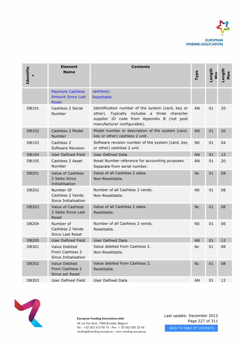
Last update: December 2012 Page 227 of 311
European Vending Association aisbl
44 rue Van Eyck, 1000 Brussels, Belgium Tel.: +32 (0)2 512 00 75 - Fax: + 32 (0)2 502 23 42 [email protected] - www.vending-europe.eu
Iden
tifi
er
Element Name
Contents
Typ
e
Len
gth
M
in
Len
gth
M
ax
Payment Cashless Amount Since Last Reset
cashless). Resettable.
DB101 Cashless 2 Serial Number
Identification number of the system (card, key or other). Typically includes a three character supplier ID code from Appendix B (not post manufacturer configurable).
AN 01 20
DB102 Cashless 2 Model Number
Model number or description of the system (card, key or other) cashless 2 unit.
AN 01 20
DB103 Cashless 2 Software Revision
Software revision number of the system (card, key or other) cashless 2 unit.
N0 01 04
DB104 User Defined Field User Defined Data AN 01 12
DB105 Cashless 2 Asset Number
Asset Number reference for accounting purposes. Separate from serial number.
AN 01 20
DB201 Value of Cashless 2 Sales Since Initiatlisation
Value of all Cashless 2 sales. Non-Resettable.
Nc 01 08
DB202 Number Of Cashless 2 Vends Since Initialisation
Number of all Cashless 2 vends. Non-Resettable.
N0 01 08
DB203 Value of Cashless 2 Sales Since Last Reset
Value of all Cashless 2 sales. Resettable.
Nc 01 08
DB204 Number of Cashless 2 Vends Since Last Reset
Number of all Cashless 2 vends. Resettable.
N0 01 06
DB205 User Defined Field User Defined Data AN 01 12
DB301 Value Debited From Cashless 2 Since Initialisation
Value debited from Cashless 2. Non-Resettable.
Nc 01 08
DB302 Value Debited From Cashless 2 Since ast Reset
Value debited from Cashless 2. Resettable.
Nc 01 08
DB303 User Defined Field User Defined Data AN 01 12
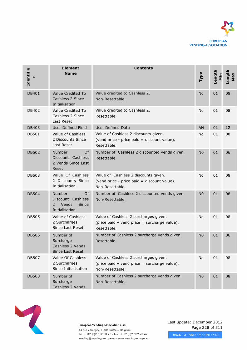
Last update: December 2012 Page 228 of 311
European Vending Association aisbl
44 rue Van Eyck, 1000 Brussels, Belgium Tel.: +32 (0)2 512 00 75 - Fax: + 32 (0)2 502 23 42 [email protected] - www.vending-europe.eu
Iden
tifi
er
Element Name
Contents
Typ
e
Len
gth
M
in
Len
gth
M
ax
DB401 Value Credited To Cashless 2 Since Initialisation
Value credited to Cashless 2. Non-Resettable.
Nc 01 08
DB402 Value Credited To Cashless 2 Since Last Reset
Value credited to Cashless 2. Resettable.
Nc 01 08
DB403 User Defined Field User Defined Data AN 01 12
DB501 Value of Cashless 2 Discounts Since Last Reset
Value of Cashless 2 discounts given. (vend price - price paid = discount value). Resettable.
Nc 01 08
DB502 Number Of Discount Cashless 2 Vends Since Last Reset
Number of Cashless 2 discounted vends given. Resettable.
N0 01 06
DB503 Value Of Cashless 2 Discounts Since Initialisation
Value of Cashless 2 discounts given. (vend price - price paid = discount value). Non-Resettable.
Nc 01 08
DB504 Number Of Discount Cashless 2 Vends Since Initialisation
Number of Cashless 2 discounted vends given. Non-Resettable.
N0 01 08
DB505 Value of Cashless 2 Surcharges Since Last Reset
Value of Cashless 2 surcharges given. (price paid – vend price = surcharge value). Resettable.
Nc 01 08
DB506 Number of Surcharge Cashless 2 Vends Since Last Reset
Number of Cashless 2 surcharge vends given. Resettable.
N0 01 06
DB507 Value Of Cashless 2 Surcharges Since Initialisation
Value of Cashless 2 surcharges given. (price paid – vend price = surcharge value). Non-Resettable.
Nc 01 08
DB508 Number of Surcharge Cashless 2 Vends
Number of Cashless 2 surcharge vends given. Non-Resettable.
N0 01 08
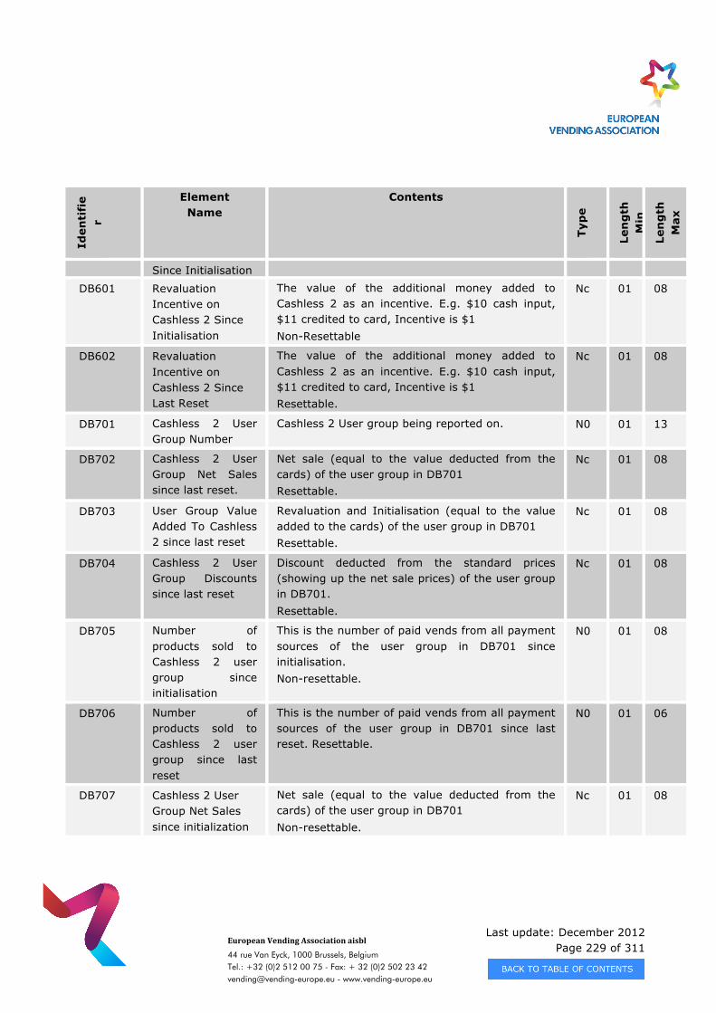
Last update: December 2012 Page 229 of 311
European Vending Association aisbl
44 rue Van Eyck, 1000 Brussels, Belgium Tel.: +32 (0)2 512 00 75 - Fax: + 32 (0)2 502 23 42 [email protected] - www.vending-europe.eu
Iden
tifi
er
Element Name
Contents
Typ
e
Len
gth
M
in
Len
gth
M
ax
Since Initialisation
DB601 Revaluation Incentive on Cashless 2 Since Initialisation
The value of the additional money added to Cashless 2 as an incentive. E.g. $10 cash input, $11 credited to card, Incentive is $1 Non-Resettable
Nc 01 08
DB602 Revaluation Incentive on Cashless 2 Since Last Reset
The value of the additional money added to Cashless 2 as an incentive. E.g. $10 cash input, $11 credited to card, Incentive is $1 Resettable.
Nc 01 08
DB701 Cashless 2 User Group Number
Cashless 2 User group being reported on. N0 01 13
DB702 Cashless 2 User Group Net Sales since last reset.
Net sale (equal to the value deducted from the cards) of the user group in DB701 Resettable.
Nc 01 08
DB703 User Group Value Added To Cashless 2 since last reset
Revaluation and Initialisation (equal to the value added to the cards) of the user group in DB701 Resettable.
Nc 01 08
DB704 Cashless 2 User Group Discounts since last reset
Discount deducted from the standard prices (showing up the net sale prices) of the user group in DB701. Resettable.
Nc 01 08
DB705 Number of products sold to Cashless 2 user group since initialisation
This is the number of paid vends from all payment sources of the user group in DB701 since initialisation. Non-resettable.
N0 01 08
DB706 Number of products sold to Cashless 2 user group since last reset
This is the number of paid vends from all payment sources of the user group in DB701 since last reset. Resettable.
N0 01 06
DB707 Cashless 2 User Group Net Sales since initialization
Net sale (equal to the value deducted from the cards) of the user group in DB701 Non-resettable.
Nc 01 08
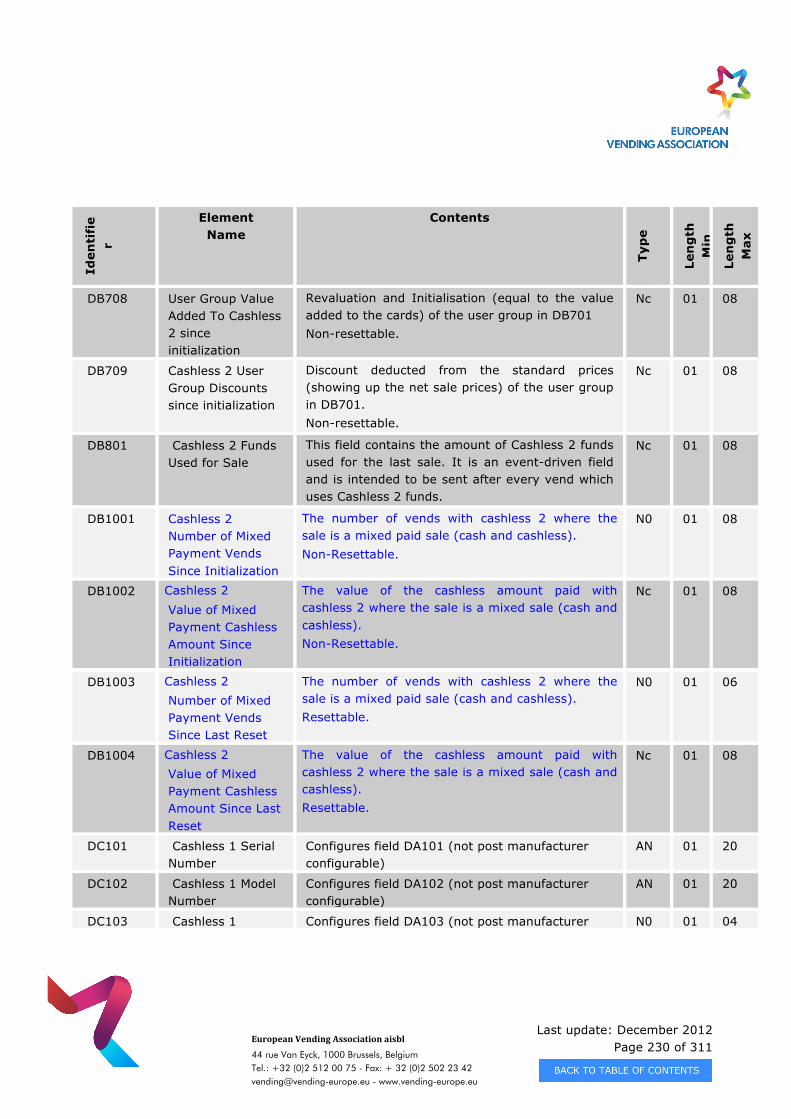
Last update: December 2012 Page 230 of 311
European Vending Association aisbl
44 rue Van Eyck, 1000 Brussels, Belgium Tel.: +32 (0)2 512 00 75 - Fax: + 32 (0)2 502 23 42 [email protected] - www.vending-europe.eu
Iden
tifi
er
Element Name
Contents
Typ
e
Len
gth
M
in
Len
gth
M
ax
DB708 User Group Value Added To Cashless 2 since initialization
Revaluation and Initialisation (equal to the value added to the cards) of the user group in DB701 Non-resettable.
Nc 01 08
DB709 Cashless 2 User Group Discounts since initialization
Discount deducted from the standard prices (showing up the net sale prices) of the user group in DB701. Non-resettable.
Nc 01 08
DB801 Cashless 2 Funds Used for Sale
This field contains the amount of Cashless 2 funds used for the last sale. It is an event-driven field and is intended to be sent after every vend which uses Cashless 2 funds.
Nc 01 08
DB1001 Cashless 2 Number of Mixed Payment Vends Since Initialization
The number of vends with cashless 2 where the sale is a mixed paid sale (cash and cashless). Non-Resettable.
N0 01 08
DB1002 Cashless 2 Value of Mixed Payment Cashless Amount Since Initialization
The value of the cashless amount paid with cashless 2 where the sale is a mixed sale (cash and cashless). Non-Resettable.
Nc 01 08
DB1003 Cashless 2 Number of Mixed Payment Vends Since Last Reset
The number of vends with cashless 2 where the sale is a mixed paid sale (cash and cashless). Resettable.
N0 01 06
DB1004 Cashless 2 Value of Mixed Payment Cashless Amount Since Last Reset
The value of the cashless amount paid with cashless 2 where the sale is a mixed sale (cash and cashless). Resettable.
Nc 01 08
DC101 Cashless 1 Serial Number
Configures field DA101 (not post manufacturer configurable)
AN 01 20
DC102 Cashless 1 Model Number
Configures field DA102 (not post manufacturer configurable)
AN 01 20
DC103 Cashless 1 Configures field DA103 (not post manufacturer N0 01 04
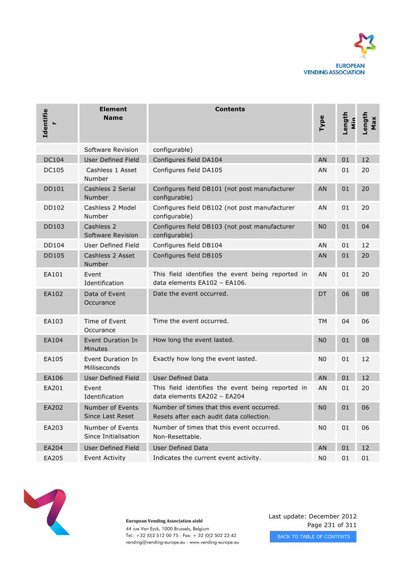
Last update: December 2012 Page 231 of 311
European Vending Association aisbl
44 rue Van Eyck, 1000 Brussels, Belgium Tel.: +32 (0)2 512 00 75 - Fax: + 32 (0)2 502 23 42 [email protected] - www.vending-europe.eu
Iden
tifi
er
Element Name
Contents
Typ
e
Len
gth
M
in
Len
gth
M
ax
Software Revision configurable)
DC104 User Defined Field Configures field DA104 AN 01 12
DC105 Cashless 1 Asset Number
Configures field DA105 AN 01 20
DD101 Cashless 2 Serial Number
Configures field DB101 (not post manufacturer configurable)
AN 01 20
DD102 Cashless 2 Model Number
Configures field DB102 (not post manufacturer configurable)
AN 01 20
DD103 Cashless 2 Software Revision
Configures field DB103 (not post manufacturer configurable)
N0 01 04
DD104 User Defined Field Configures field DB104 AN 01 12
DD105 Cashless 2 Asset Number
Configures field DB105 AN 01 20
EA101 Event Identification
This field identifies the event being reported in data elements EA102 – EA106.
AN 01 20
EA102 Data of Event Occurance
Date the event occurred. DT 06 08
EA103 Time of Event Occurance
Time the event occurred. TM 04 06
EA104 Event Duration In Minutes
How long the event lasted. N0 01 08
EA105 Event Duration In Milliseconds
Exactly how long the event lasted. N0 01 12
EA106 User Defined Field User Defined Data AN 01 12
EA201 Event Identification
This field identifies the event being reported in data elements EA202 – EA204
AN 01 20
EA202 Number of Events Since Last Reset
Number of times that this event occurred. Resets after each audit data collection.
N0 01 06
EA203 Number of Events Since Initialisation
Number of times that this event occurred. Non-Resettable.
N0 01 06
EA204 User Defined Field User Defined Data AN 01 12
EA205 Event Activity Indicates the current event activity. N0 01 01
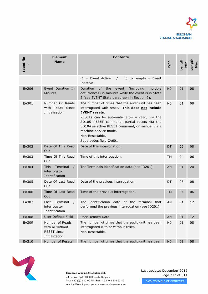
Last update: December 2012 Page 232 of 311
European Vending Association aisbl
44 rue Van Eyck, 1000 Brussels, Belgium Tel.: +32 (0)2 512 00 75 - Fax: + 32 (0)2 502 23 42 [email protected] - www.vending-europe.eu
Iden
tifi
er
Element Name
Contents
Typ
e
Len
gth
M
in
Len
gth
M
ax
(1 = Event Active / 0 (or empty = Event Inactive
EA206 Event Duration In Minutes
Duration of the event (including multiple occurrences) in minutes while the event is in State 2 (see EVENT State paragraph in Section 2).
N0 01 08
EA301 Number Of Reads with RESET Since Initialisation
The number of times that the audit unit has been interrogated with reset. This does not include EVENT resets. RESETs can be automatic after a read, via the SD105 RESET command, partial resets via the SD104 selective RESET command, or manual via a machine service mode. Non-Resettable. Supersedes field CA601
N0 01 08
EA302 Date Of This Read Out
Date of this interrogation. DT 06 08
EA303 Time Of This Read Out
Time of this interrogation. TM 04 06
EA304 This Terminal / interrogator Identification
The Terminals identification data (see ID201). AN 01 20
EA305 Date Of Last Read Out
Date of the previous interrogation. DT 06 08
EA306 Time Of Last Read Out
Time of the previous interrogation. TM 04 06
EA307 Last Terminal / interrogator Identification
The identification data of the terminal that performed the previous interrogation (see ID201).
AN 01 12
EA308 User Defined Field User Defined Data AN 01 12
EA309 Number of Reads with or without RESET since Initialization
The number of times that the audit unit has been interrogated with or without reset. Non-Resettable.
N0 01 08
EA310 Number of Resets The number of times that the audit unit has been N0 01 08
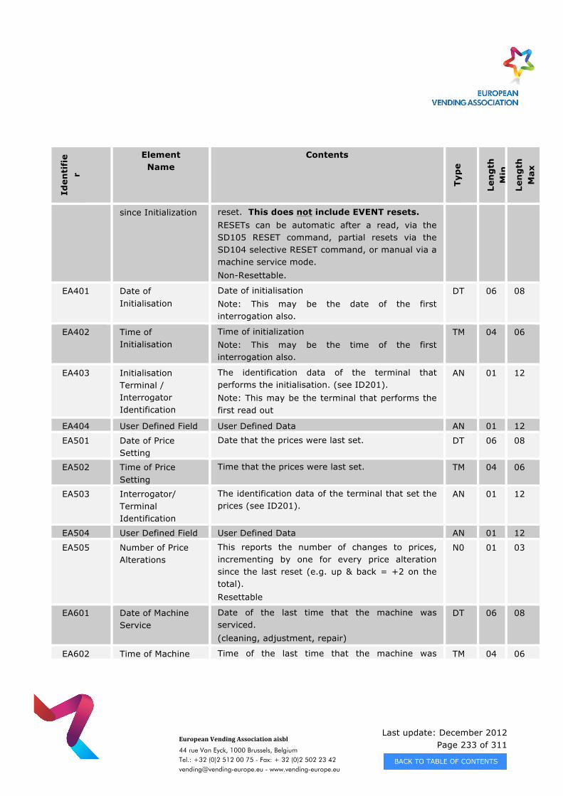
Last update: December 2012 Page 233 of 311
European Vending Association aisbl
44 rue Van Eyck, 1000 Brussels, Belgium Tel.: +32 (0)2 512 00 75 - Fax: + 32 (0)2 502 23 42 [email protected] - www.vending-europe.eu
Iden
tifi
er
Element Name
Contents
Typ
e
Len
gth
M
in
Len
gth
M
ax
since Initialization reset. This does not include EVENT resets. RESETs can be automatic after a read, via the SD105 RESET command, partial resets via the SD104 selective RESET command, or manual via a machine service mode. Non-Resettable.
EA401 Date of Initialisation
Date of initialisation Note: This may be the date of the first interrogation also.
DT 06 08
EA402 Time of Initialisation
Time of initialization Note: This may be the time of the first interrogation also.
TM 04 06
EA403 Initialisation Terminal / Interrogator Identification
The identification data of the terminal that performs the initialisation. (see ID201). Note: This may be the terminal that performs the first read out
AN 01 12
EA404 User Defined Field User Defined Data AN 01 12
EA501 Date of Price Setting
Date that the prices were last set. DT 06 08
EA502 Time of Price Setting
Time that the prices were last set. TM 04 06
EA503 Interrogator/ Terminal Identification
The identification data of the terminal that set the prices (see ID201).
AN 01 12
EA504 User Defined Field User Defined Data AN 01 12
EA505 Number of Price Alterations
This reports the number of changes to prices, incrementing by one for every price alteration since the last reset (e.g. up & back = +2 on the total). Resettable
N0 01 03
EA601 Date of Machine Service
Date of the last time that the machine was serviced. (cleaning, adjustment, repair)
DT 06 08
EA602 Time of Machine Time of the last time that the machine was TM 04 06
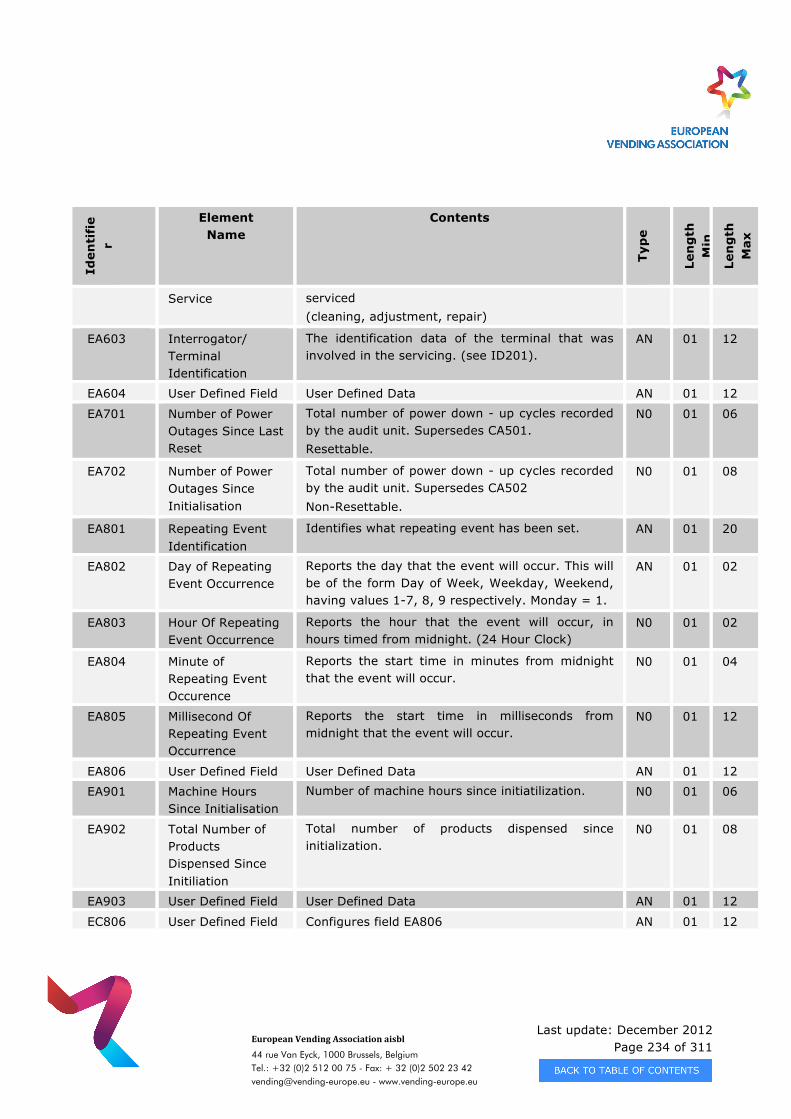
Last update: December 2012 Page 234 of 311
European Vending Association aisbl
44 rue Van Eyck, 1000 Brussels, Belgium Tel.: +32 (0)2 512 00 75 - Fax: + 32 (0)2 502 23 42 [email protected] - www.vending-europe.eu
Iden
tifi
er
Element Name
Contents
Typ
e
Len
gth
M
in
Len
gth
M
ax
Service serviced (cleaning, adjustment, repair)
EA603 Interrogator/ Terminal Identification
The identification data of the terminal that was involved in the servicing. (see ID201).
AN 01 12
EA604 User Defined Field User Defined Data AN 01 12
EA701 Number of Power Outages Since Last Reset
Total number of power down - up cycles recorded by the audit unit. Supersedes CA501. Resettable.
N0 01 06
EA702 Number of Power Outages Since Initialisation
Total number of power down - up cycles recorded by the audit unit. Supersedes CA502 Non-Resettable.
N0 01 08
EA801 Repeating Event Identification
Identifies what repeating event has been set. AN 01 20
EA802 Day of Repeating Event Occurrence
Reports the day that the event will occur. This will be of the form Day of Week, Weekday, Weekend, having values 1-7, 8, 9 respectively. Monday = 1.
AN 01 02
EA803 Hour Of Repeating Event Occurrence
Reports the hour that the event will occur, in hours timed from midnight. (24 Hour Clock)
N0 01 02
EA804 Minute of Repeating Event Occurence
Reports the start time in minutes from midnight that the event will occur.
N0 01 04
EA805 Millisecond Of Repeating Event Occurrence
Reports the start time in milliseconds from midnight that the event will occur.
N0 01 12
EA806 User Defined Field User Defined Data AN 01 12
EA901 Machine Hours Since Initialisation
Number of machine hours since initiatilization. N0 01 06
EA902 Total Number of Products Dispensed Since Initiliation
Total number of products dispensed since initialization.
N0 01 08
EA903 User Defined Field User Defined Data AN 01 12
EC806 User Defined Field Configures field EA806 AN 01 12
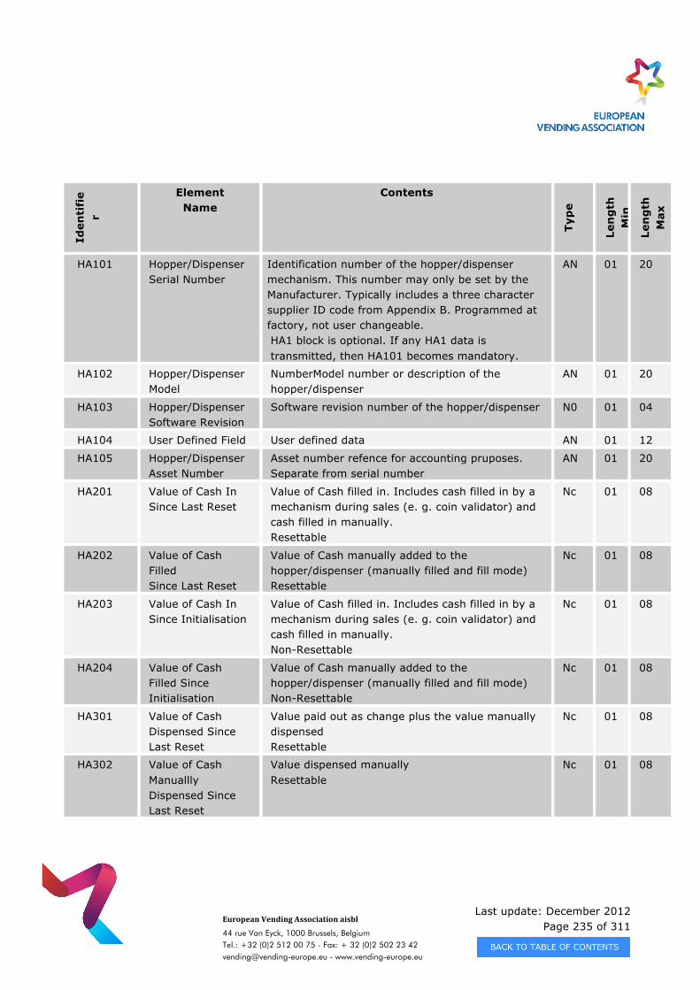
Last update: December 2012 Page 235 of 311
European Vending Association aisbl
44 rue Van Eyck, 1000 Brussels, Belgium Tel.: +32 (0)2 512 00 75 - Fax: + 32 (0)2 502 23 42 [email protected] - www.vending-europe.eu
Iden
tifi
er
Element Name
Contents
Typ
e
Len
gth
M
in
Len
gth
M
ax
HA101 Hopper/Dispenser Serial Number
Identification number of the hopper/dispenser mechanism. This number may only be set by the Manufacturer. Typically includes a three character supplier ID code from Appendix B. Programmed at factory, not user changeable. HA1 block is optional. If any HA1 data is transmitted, then HA101 becomes mandatory.
AN 01 20
HA102 Hopper/Dispenser Model
NumberModel number or description of the hopper/dispenser
AN 01 20
HA103 Hopper/Dispenser Software Revision
Software revision number of the hopper/dispenser N0 01 04
HA104 User Defined Field User defined data AN 01 12
HA105 Hopper/Dispenser Asset Number
Asset number refence for accounting pruposes. Separate from serial number
AN 01 20
HA201 Value of Cash In Since Last Reset
Value of Cash filled in. Includes cash filled in by a mechanism during sales (e. g. coin validator) and cash filled in manually. Resettable
Nc 01 08
HA202 Value of Cash Filled Since Last Reset
Value of Cash manually added to the hopper/dispenser (manually filled and fill mode) Resettable
Nc 01 08
HA203 Value of Cash In Since Initialisation
Value of Cash filled in. Includes cash filled in by a mechanism during sales (e. g. coin validator) and cash filled in manually. Non-Resettable
Nc 01 08
HA204 Value of Cash Filled Since Initialisation
Value of Cash manually added to the hopper/dispenser (manually filled and fill mode) Non-Resettable
Nc 01 08
HA301 Value of Cash Dispensed Since Last Reset
Value paid out as change plus the value manually dispensed Resettable
Nc 01 08
HA302 Value of Cash Manuallly Dispensed Since Last Reset
Value dispensed manually Resettable
Nc 01 08
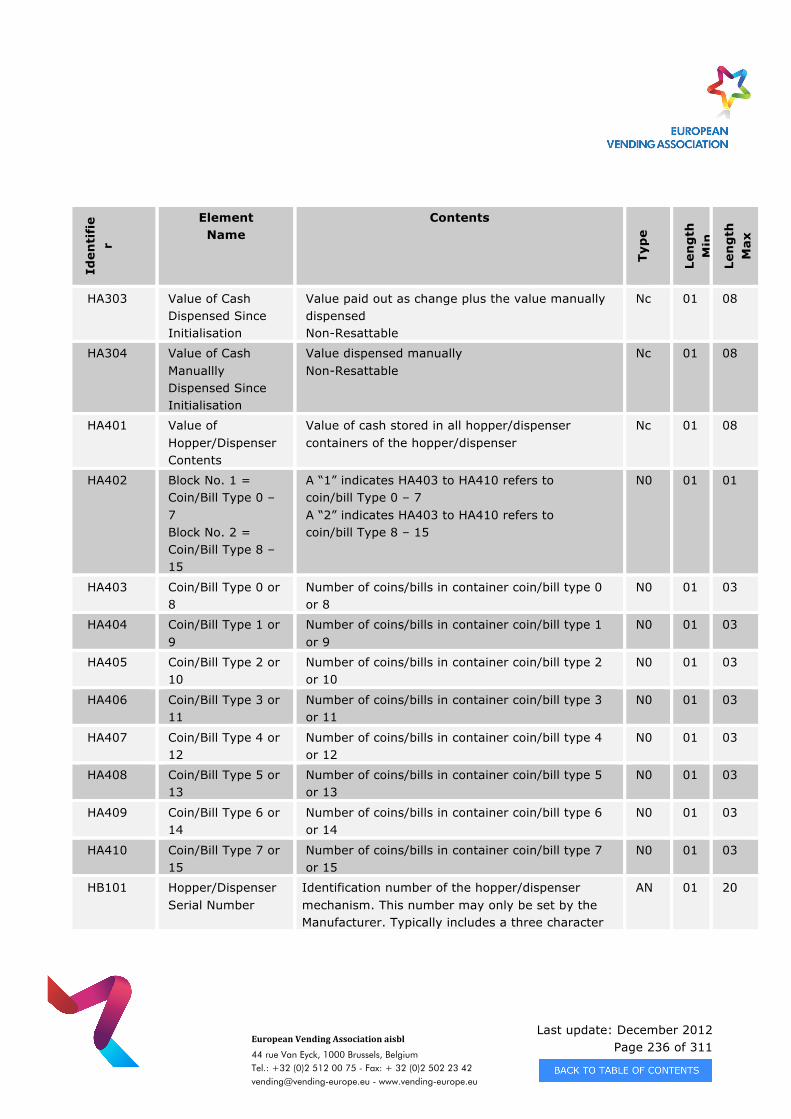
Last update: December 2012 Page 236 of 311
European Vending Association aisbl
44 rue Van Eyck, 1000 Brussels, Belgium Tel.: +32 (0)2 512 00 75 - Fax: + 32 (0)2 502 23 42 [email protected] - www.vending-europe.eu
Iden
tifi
er
Element Name
Contents
Typ
e
Len
gth
M
in
Len
gth
M
ax
HA303 Value of Cash Dispensed Since Initialisation
Value paid out as change plus the value manually dispensed Non-Resattable
Nc 01 08
HA304 Value of Cash Manuallly Dispensed Since Initialisation
Value dispensed manually Non-Resattable
Nc 01 08
HA401 Value of Hopper/Dispenser Contents
Value of cash stored in all hopper/dispenser containers of the hopper/dispenser
Nc 01 08
HA402 Block No. 1 = Coin/Bill Type 0 – 7 Block No. 2 = Coin/Bill Type 8 – 15
A “1” indicates HA403 to HA410 refers to coin/bill Type 0 – 7 A “2” indicates HA403 to HA410 refers to coin/bill Type 8 – 15
N0 01 01
HA403 Coin/Bill Type 0 or 8
Number of coins/bills in container coin/bill type 0 or 8
N0 01 03
HA404 Coin/Bill Type 1 or 9
Number of coins/bills in container coin/bill type 1 or 9
N0 01 03
HA405 Coin/Bill Type 2 or 10
Number of coins/bills in container coin/bill type 2 or 10
N0 01 03
HA406 Coin/Bill Type 3 or 11
Number of coins/bills in container coin/bill type 3 or 11
N0 01 03
HA407 Coin/Bill Type 4 or 12
Number of coins/bills in container coin/bill type 4 or 12
N0 01 03
HA408 Coin/Bill Type 5 or 13
Number of coins/bills in container coin/bill type 5 or 13
N0 01 03
HA409 Coin/Bill Type 6 or 14
Number of coins/bills in container coin/bill type 6 or 14
N0 01 03
HA410 Coin/Bill Type 7 or 15
Number of coins/bills in container coin/bill type 7 or 15
N0 01 03
HB101 Hopper/Dispenser Serial Number
Identification number of the hopper/dispenser mechanism. This number may only be set by the Manufacturer. Typically includes a three character
AN 01 20
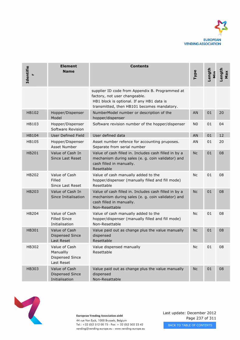
Last update: December 2012 Page 237 of 311
European Vending Association aisbl
44 rue Van Eyck, 1000 Brussels, Belgium Tel.: +32 (0)2 512 00 75 - Fax: + 32 (0)2 502 23 42 [email protected] - www.vending-europe.eu
Iden
tifi
er
Element Name
Contents
Typ
e
Len
gth
M
in
Len
gth
M
ax
supplier ID code from Appendix B. Programmed at factory, not user changeable. HB1 block is optional. If any HB1 data is transmitted, then HB101 becomes mandatory.
HB102 Hopper/Dispenser Model
NumberModel number or description of the hopper/dispenser
AN 01 20
HB103 Hopper/Dispenser Software Revision
Software revision number of the hopper/dispenser N0 01 04
HB104 User Defined Field User defined data AN 01 12
HB105 Hopper/Dispenser Asset Number
Asset number refence for accounting pruposes. Separate from serial number
AN 01 20
HB201 Value of Cash In Since Last Reset
Value of cash filled in. Includes cash filled in by a mechanism during sales (e. g. coin validator) and cash filled in manually. Resettable
Nc 01 08
HB202 Value of Cash Filled Since Last Reset
Value of cash manually added to the hopper/dispenser (manually filled and fill mode) Resettable
Nc 01 08
HB203 Value of Cash In Since Initialisation
Value of cash filled in. Includes cash filled in by a mechanism during sales (e. g. coin validator) and cash filled in manually. Non-Resettable
Nc 01 08
HB204 Value of Cash Filled Since Initialisation
Value of cash manually added to the hopper/dispenser (manually filled and fill mode) Non-Resettable
Nc 01 08
HB301 Value of Cash Dispensed Since Last Reset
Value paid out as change plus the value manually dispensed Resettable
Nc 01 08
HB302 Value of Cash Manuallly Dispensed Since Last Reset
Value dispensed manually Resettable
Nc 01 08
HB303 Value of Cash Dispensed Since Initialisation
Value paid out as change plus the value manually dispensed Non-Resattable
Nc 01 08
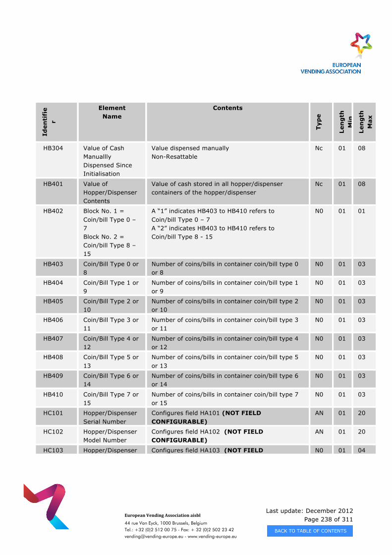
Last update: December 2012 Page 238 of 311
European Vending Association aisbl
44 rue Van Eyck, 1000 Brussels, Belgium Tel.: +32 (0)2 512 00 75 - Fax: + 32 (0)2 502 23 42 [email protected] - www.vending-europe.eu
Iden
tifi
er
Element Name
Contents
Typ
e
Len
gth
M
in
Len
gth
M
ax
HB304 Value of Cash Manuallly Dispensed Since Initialisation
Value dispensed manually Non-Resattable
Nc 01 08
HB401 Value of Hopper/Dispenser Contents
Value of cash stored in all hopper/dispenser containers of the hopper/dispenser
Nc 01 08
HB402 Block No. 1 = Coin/bill Type 0 – 7 Block No. 2 = Coin/bill Type 8 – 15
A “1” indicates HB403 to HB410 refers to Coin/bill Type 0 – 7 A “2” indicates HB403 to HB410 refers to Coin/bill Type 8 - 15
N0 01 01
HB403 Coin/Bill Type 0 or 8
Number of coins/bills in container coin/bill type 0 or 8
N0 01 03
HB404 Coin/Bill Type 1 or 9
Number of coins/bills in container coin/bill type 1 or 9
N0 01 03
HB405 Coin/Bill Type 2 or 10
Number of coins/bills in container coin/bill type 2 or 10
N0 01 03
HB406 Coin/Bill Type 3 or 11
Number of coins/bills in container coin/bill type 3 or 11
N0 01 03
HB407 Coin/Bill Type 4 or 12
Number of coins/bills in container coin/bill type 4 or 12
N0 01 03
HB408 Coin/Bill Type 5 or 13
Number of coins/bills in container coin/bill type 5 or 13
N0 01 03
HB409 Coin/Bill Type 6 or 14
Number of coins/bills in container coin/bill type 6 or 14
N0 01 03
HB410 Coin/Bill Type 7 or 15
Number of coins/bills in container coin/bill type 7 or 15
N0 01 03
HC101 Hopper/Dispenser Serial Number
Configures field HA101 (NOT FIELD CONFIGURABLE)
AN 01 20
HC102 Hopper/Dispenser Model Number
Configures field HA102 (NOT FIELD CONFIGURABLE)
AN 01 20
HC103 Hopper/Dispenser Configures field HA103 (NOT FIELD N0 01 04
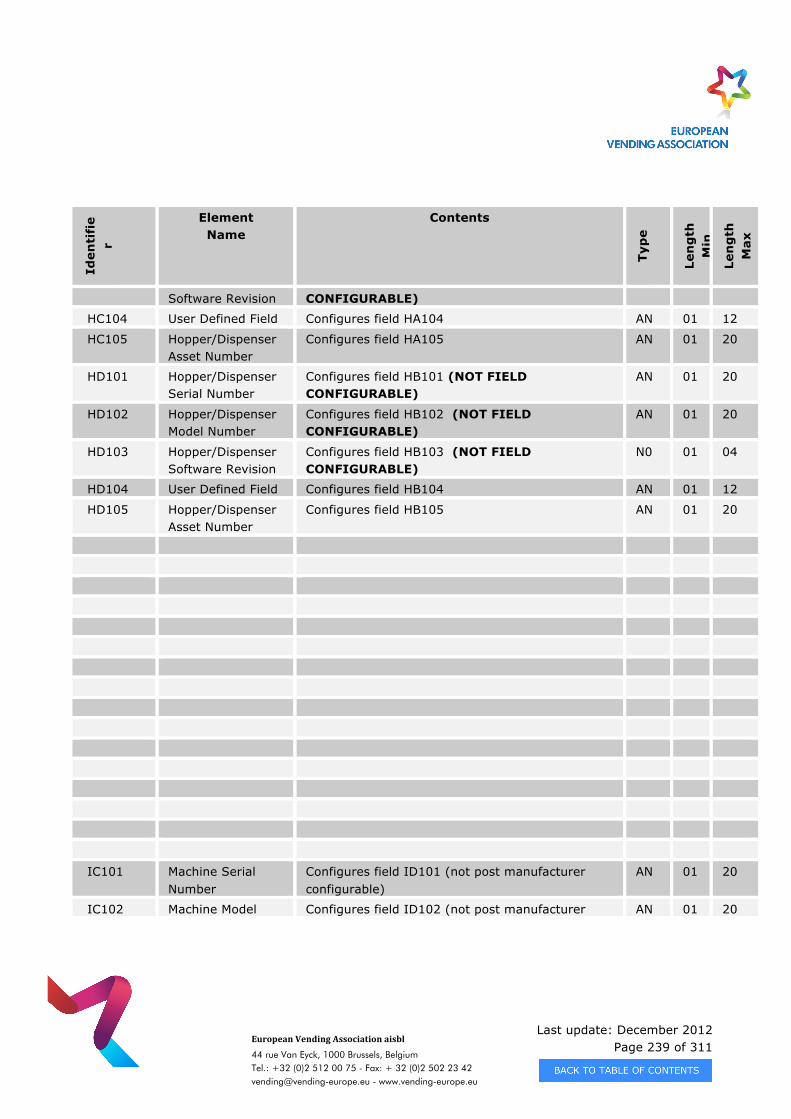
Last update: December 2012 Page 239 of 311
European Vending Association aisbl
44 rue Van Eyck, 1000 Brussels, Belgium Tel.: +32 (0)2 512 00 75 - Fax: + 32 (0)2 502 23 42 [email protected] - www.vending-europe.eu
Iden
tifi
er
Element Name
Contents
Typ
e
Len
gth
M
in
Len
gth
M
ax
Software Revision CONFIGURABLE)
HC104 User Defined Field Configures field HA104 AN 01 12
HC105 Hopper/Dispenser Asset Number
Configures field HA105 AN 01 20
HD101 Hopper/Dispenser Serial Number
Configures field HB101 (NOT FIELD CONFIGURABLE)
AN 01 20
HD102 Hopper/Dispenser Model Number
Configures field HB102 (NOT FIELD CONFIGURABLE)
AN 01 20
HD103 Hopper/Dispenser Software Revision
Configures field HB103 (NOT FIELD CONFIGURABLE)
N0 01 04
HD104 User Defined Field Configures field HB104 AN 01 12
HD105 Hopper/Dispenser Asset Number
Configures field HB105 AN 01 20
IC101 Machine Serial Number
Configures field ID101 (not post manufacturer configurable)
AN 01 20
IC102 Machine Model Configures field ID102 (not post manufacturer AN 01 20
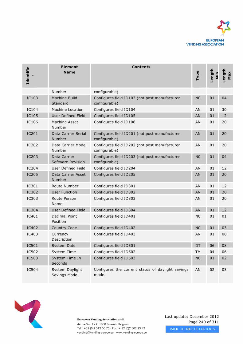
Last update: December 2012 Page 240 of 311
European Vending Association aisbl
44 rue Van Eyck, 1000 Brussels, Belgium Tel.: +32 (0)2 512 00 75 - Fax: + 32 (0)2 502 23 42 [email protected] - www.vending-europe.eu
Iden
tifi
er
Element Name
Contents
Typ
e
Len
gth
M
in
Len
gth
M
ax
Number configurable)
IC103 Machine Build Standard
Configures field ID103 (not post manufacturer configurable)
N0 01 04
IC104 Machine Location Configures field ID104 AN 01 30
IC105 User Defined Field Configures field ID105 AN 01 12
IC106 Machine Asset Number
Configures field ID106 AN 01 20
IC201 Data Carrier Serial Number
Configures field ID201 (not post manufacturer configurable)
AN 01 20
IC202 Data Carrier Model Number
Configures field ID202 (not post manufacturer configurable)
AN 01 20
IC203 Data Carrier Software Revision
Configures field ID203 (not post manufacturer configurable)
N0 01 04
IC204 User Defined Field Configures field ID204 AN 01 12
IC205 Data Carrier Asset Number
Configures field ID205 AN 01 20
IC301 Route Number Configures field ID301 AN 01 12
IC302 User Function Configures field ID302 AN 01 20
IC303 Route Person Name
Configures field ID303 AN 01 20
IC304 User Defined Field Configures field ID304 AN 01 12
IC401 Decimal Point Position
Configures field ID401 N0 01 01
IC402 Country Code Configures field ID402 N0 01 03
IC403 Currency Description
Configures field ID403 AN 01 08
IC501 System Date Configures field ID501 DT 06 08
IC502 System Time Configures field ID502 TM 04 06
IC503 System Time In Seconds
Configures field ID503 N0 01 02
IC504 System Daylight Savings Mode
Configures the current status of daylight savings mode.
AN 02 03
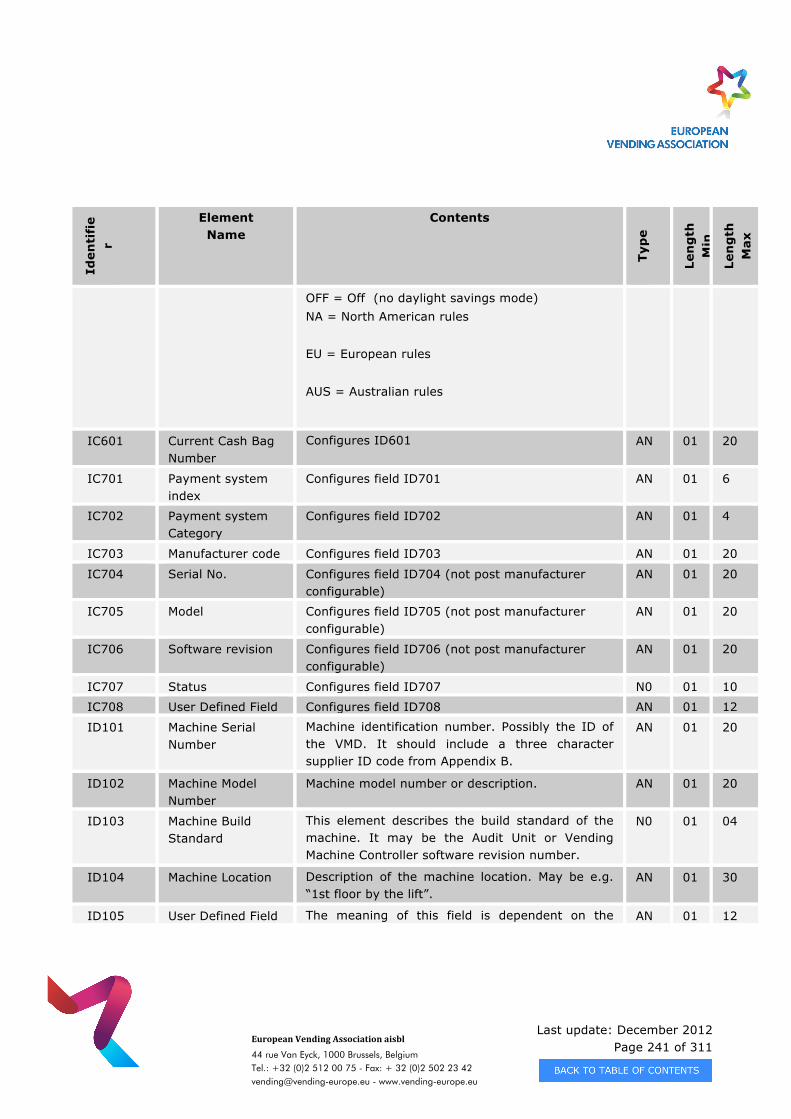
Last update: December 2012 Page 241 of 311
European Vending Association aisbl
44 rue Van Eyck, 1000 Brussels, Belgium Tel.: +32 (0)2 512 00 75 - Fax: + 32 (0)2 502 23 42 [email protected] - www.vending-europe.eu
Iden
tifi
er
Element Name
Contents
Typ
e
Len
gth
M
in
Len
gth
M
ax
OFF = Off (no daylight savings mode) NA = North American rules EU = European rules AUS = Australian rules
IC601 Current Cash Bag Number
Configures ID601 AN 01 20
IC701 Payment system index
Configures field ID701 AN 01 6
IC702 Payment system Category
Configures field ID702 AN 01 4
IC703 Manufacturer code Configures field ID703 AN 01 20
IC704 Serial No. Configures field ID704 (not post manufacturer configurable)
AN 01 20
IC705 Model Configures field ID705 (not post manufacturer configurable)
AN 01 20
IC706 Software revision Configures field ID706 (not post manufacturer configurable)
AN 01 20
IC707 Status Configures field ID707 N0 01 10
IC708 User Defined Field Configures field ID708 AN 01 12
ID101 Machine Serial Number
Machine identification number. Possibly the ID of the VMD. It should include a three character supplier ID code from Appendix B.
AN 01 20
ID102 Machine Model Number
Machine model number or description. AN 01 20
ID103 Machine Build Standard
This element describes the build standard of the machine. It may be the Audit Unit or Vending Machine Controller software revision number.
N0 01 04
ID104 Machine Location Description of the machine location. May be e.g. “1st floor by the lift”.
AN 01 30
ID105 User Defined Field The meaning of this field is dependent on the AN 01 12
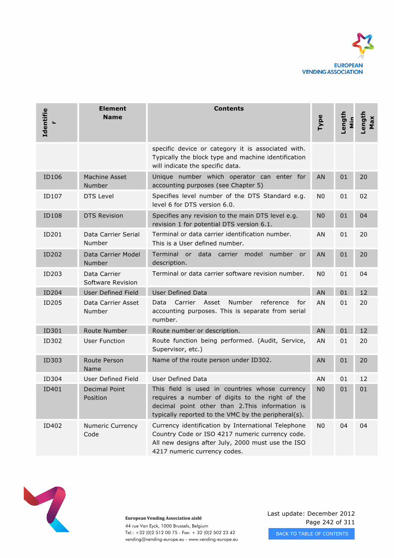
Last update: December 2012 Page 242 of 311
European Vending Association aisbl
44 rue Van Eyck, 1000 Brussels, Belgium Tel.: +32 (0)2 512 00 75 - Fax: + 32 (0)2 502 23 42 [email protected] - www.vending-europe.eu
Iden
tifi
er
Element Name
Contents
Typ
e
Len
gth
M
in
Len
gth
M
ax
specific device or category it is associated with. Typically the block type and machine identification will indicate the specific data.
ID106 Machine Asset Number
Unique number which operator can enter for accounting purposes (see Chapter 5)
AN 01 20
ID107 DTS Level Specifies level number of the DTS Standard e.g. level 6 for DTS version 6.0.
N0 01 02
ID108 DTS Revision Specifies any revision to the main DTS level e.g. revision 1 for potential DTS version 6.1.
N0 01 04
ID201 Data Carrier Serial Number
Terminal or data carrier identification number. This is a User defined number.
AN 01 20
ID202 Data Carrier Model Number
Terminal or data carrier model number or description.
AN 01 20
ID203 Data Carrier Software Revision
Terminal or data carrier software revision number. N0 01 04
ID204 User Defined Field User Defined Data AN 01 12
ID205 Data Carrier Asset Number
Data Carrier Asset Number reference for accounting purposes. This is separate from serial number.
AN 01 20
ID301 Route Number Route number or description. AN 01 12
ID302 User Function Route function being performed. (Audit, Service, Supervisor, etc.)
AN 01 20
ID303 Route Person Name
Name of the route person under ID302. AN 01 20
ID304 User Defined Field User Defined Data AN 01 12
ID401 Decimal Point Position
This field is used in countries whose currency requires a number of digits to the right of the decimal point other than 2.This information is typically reported to the VMC by the peripheral(s).
N0 01 01
ID402 Numeric Currency Code
Currency identification by International Telephone Country Code or ISO 4217 numeric currency code. All new designs after July, 2000 must use the ISO 4217 numeric currency codes.
N0 04 04
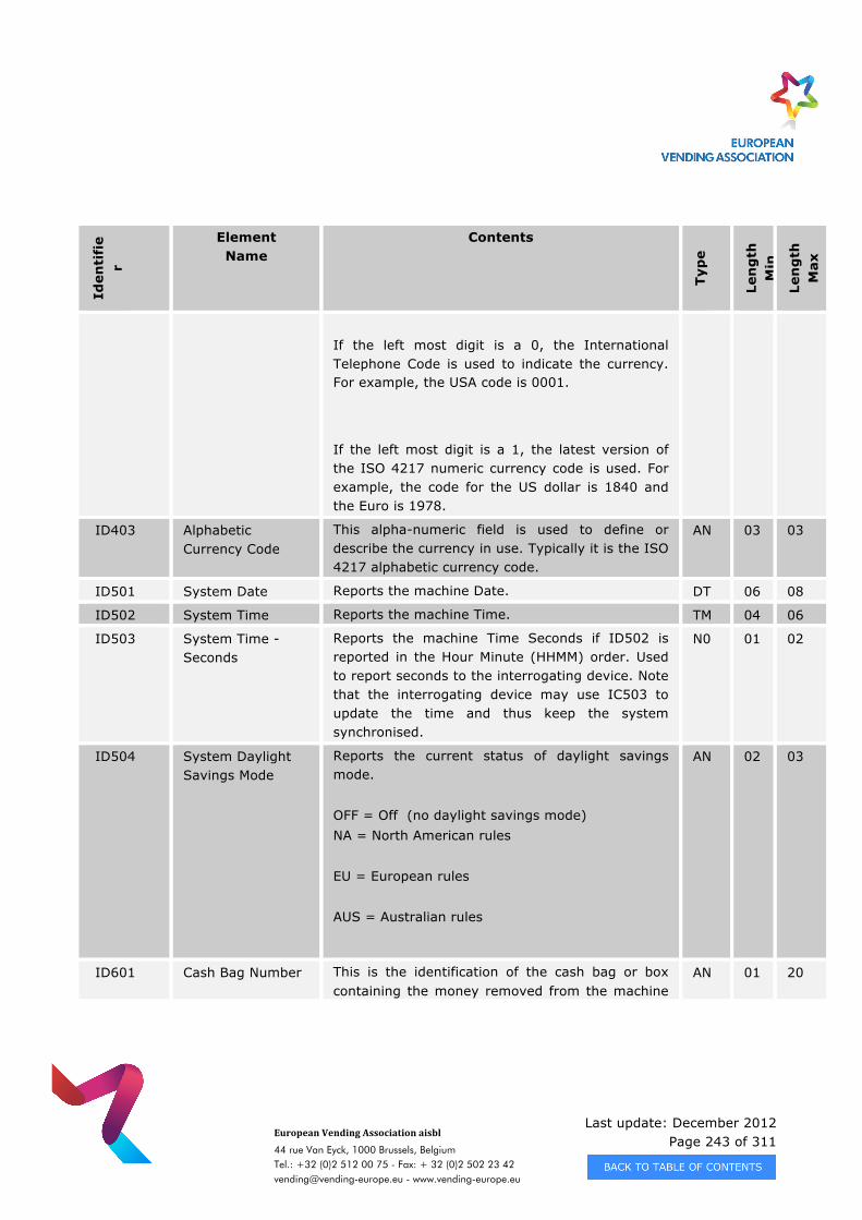
Last update: December 2012 Page 243 of 311
European Vending Association aisbl
44 rue Van Eyck, 1000 Brussels, Belgium Tel.: +32 (0)2 512 00 75 - Fax: + 32 (0)2 502 23 42 [email protected] - www.vending-europe.eu
Iden
tifi
er
Element Name
Contents
Typ
e
Len
gth
M
in
Len
gth
M
ax
If the left most digit is a 0, the International Telephone Code is used to indicate the currency. For example, the USA code is 0001.
If the left most digit is a 1, the latest version of the ISO 4217 numeric currency code is used. For example, the code for the US dollar is 1840 and the Euro is 1978.
ID403 Alphabetic Currency Code
This alpha-numeric field is used to define or describe the currency in use. Typically it is the ISO 4217 alphabetic currency code.
AN 03 03
ID501 System Date Reports the machine Date. DT 06 08
ID502 System Time Reports the machine Time. TM 04 06
ID503 System Time - Seconds
Reports the machine Time Seconds if ID502 is reported in the Hour Minute (HHMM) order. Used to report seconds to the interrogating device. Note that the interrogating device may use IC503 to update the time and thus keep the system synchronised.
N0 01 02
ID504 System Daylight Savings Mode
Reports the current status of daylight savings mode. OFF = Off (no daylight savings mode) NA = North American rules EU = European rules AUS = Australian rules
AN 02 03
ID601 Cash Bag Number This is the identification of the cash bag or box containing the money removed from the machine
AN 01 20
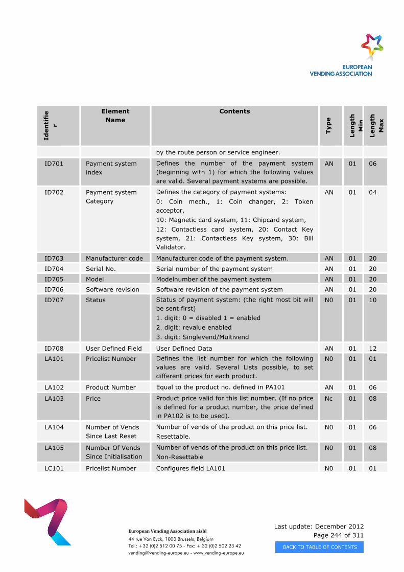
Last update: December 2012 Page 244 of 311
European Vending Association aisbl
44 rue Van Eyck, 1000 Brussels, Belgium Tel.: +32 (0)2 512 00 75 - Fax: + 32 (0)2 502 23 42 [email protected] - www.vending-europe.eu
Iden
tifi
er
Element Name
Contents
Typ
e
Len
gth
M
in
Len
gth
M
ax
by the route person or service engineer.
ID701 Payment system index
Defines the number of the payment system (beginning with 1) for which the following values are valid. Several payment systems are possible.
AN 01 06
ID702 Payment system Category
Defines the category of payment systems: 0: Coin mech., 1: Coin changer, 2: Token acceptor, 10: Magnetic card system, 11: Chipcard system, 12: Contactless card system, 20: Contact Key system, 21: Contactless Key system, 30: Bill Validator.
AN 01 04
ID703 Manufacturer code Manufacturer code of the payment system. AN 01 20
ID704 Serial No. Serial number of the payment system AN 01 20
ID705 Model Modelnumber of the payment system AN 01 20
ID706 Software revision Software revision of the payment system AN 01 20
ID707 Status Status of payment system: (the right most bit will be sent first) 1. digit: 0 = disabled 1 = enabled 2. digit: revalue enabled 3. digit: Singlevend/Multivend
N0 01 10
ID708 User Defined Field User Defined Data AN 01 12
LA101 Pricelist Number Defines the list number for which the following values are valid. Several Lists possible, to set different prices for each product.
N0 01 01
LA102 Product Number Equal to the product no. defined in PA101 AN 01 06
LA103 Price Product price valid for this list number. (If no price is defined for a product number, the price defined in PA102 is to be used).
Nc 01 08
LA104 Number of Vends Since Last Reset
Number of vends of the product on this price list. Resettable.
N0 01 06
LA105 Number Of Vends Since Initialisation
Number of vends of the product on this price list. Non-Resettable
N0 01 08
LC101 Pricelist Number Configures field LA101 N0 01 01
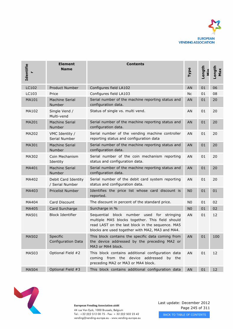
Last update: December 2012 Page 245 of 311
European Vending Association aisbl
44 rue Van Eyck, 1000 Brussels, Belgium Tel.: +32 (0)2 512 00 75 - Fax: + 32 (0)2 502 23 42 [email protected] - www.vending-europe.eu
Iden
tifi
er
Element Name
Contents
Typ
e
Len
gth
M
in
Len
gth
M
ax
LC102 Product Number Configures field LA102 AN 01 06
LC103 Price Configures field LA103 Nc 01 08
MA101 Machine Serial Number
Serial number of the machine reporting status and configuration data.
AN 01 20
MA102 Single Vend / Multi-vend
Status of single vs. multi vend. AN 01 20
MA201 Machine Serial Number
Serial number of the machine reporting status and configuration data.
AN 01 20
MA202 VMC Identity / Serial Number
Serial number of the vending machine controller reporting status and configuration data
AN 01 20
MA301 Machine Serial Number
Serial number of the machine reporting status and configuration data.
AN 01 20
MA302 Coin Mechanism Identity
Serial number of the coin mechanism reporting status and configuration data.
AN 01 20
MA401 Machine Serial Number
Serial number of the machine reporting status and configuration data.
AN 01 20
MA402 Debit Card Identity / Serial Number
Serial number of the debit card system reporting status and configuration data.
AN 01 20
MA403 Pricelist Number Identifies the price list whose card discount is reported.
N0 01 01
MA404 Card Discount The discount in percent of the standard price. N0 01 02
MA405 Card Surcharge Surcharge in % N0 01 02
MA501 Block Identifier Sequential block number used for stringing multiple MA5 blocks together. This field should read LAST on the last block in the sequence. MA5 blocks are used together with MA2, MA3 and MA4.
AN 01 12
MA502 Specific Configuration Data
This block contains the specific data coming from the device addressed by the preceding MA2 or MA3 or MA4 block.
AN 01 100
MA503 Optional Field #2 This block contains additional configuration data coming from the device addressed by the preceding MA2 or MA3 or MA4 block.
AN 01 12
MA504 Optional Field #3 This block contains additional configuration data AN 01 12
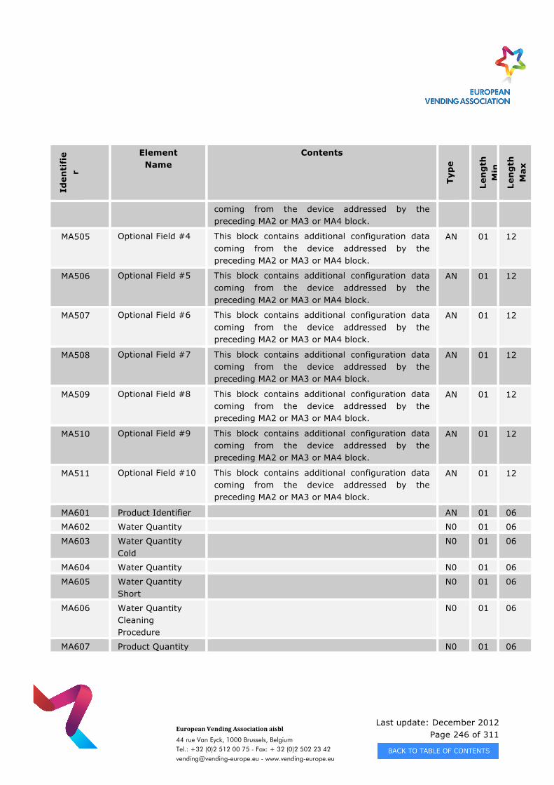
Last update: December 2012 Page 246 of 311
European Vending Association aisbl
44 rue Van Eyck, 1000 Brussels, Belgium Tel.: +32 (0)2 512 00 75 - Fax: + 32 (0)2 502 23 42 [email protected] - www.vending-europe.eu
Iden
tifi
er
Element Name
Contents
Typ
e
Len
gth
M
in
Len
gth
M
ax
coming from the device addressed by the preceding MA2 or MA3 or MA4 block.
MA505 Optional Field #4 This block contains additional configuration data coming from the device addressed by the preceding MA2 or MA3 or MA4 block.
AN 01 12
MA506 Optional Field #5 This block contains additional configuration data coming from the device addressed by the preceding MA2 or MA3 or MA4 block.
AN 01 12
MA507 Optional Field #6 This block contains additional configuration data coming from the device addressed by the preceding MA2 or MA3 or MA4 block.
AN 01 12
MA508 Optional Field #7 This block contains additional configuration data coming from the device addressed by the preceding MA2 or MA3 or MA4 block.
AN 01 12
MA509 Optional Field #8 This block contains additional configuration data coming from the device addressed by the preceding MA2 or MA3 or MA4 block.
AN 01 12
MA510 Optional Field #9 This block contains additional configuration data coming from the device addressed by the preceding MA2 or MA3 or MA4 block.
AN 01 12
MA511 Optional Field #10 This block contains additional configuration data coming from the device addressed by the preceding MA2 or MA3 or MA4 block.
AN 01 12
MA601 Product Identifier AN 01 06
MA602 Water Quantity N0 01 06
MA603 Water Quantity Cold
N0 01 06
MA604 Water Quantity N0 01 06
MA605 Water Quantity Short
N0 01 06
MA606 Water Quantity Cleaning Procedure
N0 01 06
MA607 Product Quantity N0 01 06
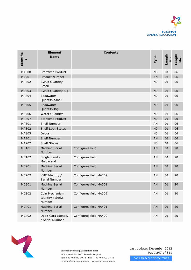
Last update: December 2012 Page 247 of 311
European Vending Association aisbl
44 rue Van Eyck, 1000 Brussels, Belgium Tel.: +32 (0)2 512 00 75 - Fax: + 32 (0)2 502 23 42 [email protected] - www.vending-europe.eu
Iden
tifi
er
Element Name
Contents
Typ
e
Len
gth
M
in
Len
gth
M
ax
MA608 Starttime Product N0 01 06
MA701 Product Number AN 01 06
MA702 Syrup Quantity Small
N0 01 06
MA703 Syrup Quantity Big N0 01 06
MA704 Sodawater Quantity Small
N0 01 06
MA705 Sodawater Quantity Big
N0 01 06
MA706 Water Quantity N0 01 06
MA707 Starttime Product N0 01 06
MA801 Shelf Number AN 01 06
MA802 Shelf Lock Status N0 01 06
MA803 Deposit N0 01 06
MA901 Shelf Number AN 01 06
MA902 Shelf Status N0 01 06
MC101 Machine Serial Number
Configures field AN 01 20
MC102 Single Vend / Multi-vend
Configures field AN 01 20
MC201 Machine Serial Number
Configures field AN 01 20
MC202 VMC Identity / Serial Number
Configures field MA202 AN 01 20
MC301 Machine Serial Number
Configures field MA301 AN 01 20
MC302 Coin Mechanism Identity / Serial Number
Configures field MA302 AN 01 20
MC401 Machine Serial Number
Configures field MA401 AN 01 20
MC402 Debit Card Identity / Serial Number
Configures field MA402 AN 01 20
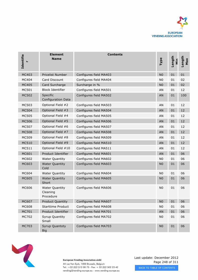
Last update: December 2012 Page 248 of 311
European Vending Association aisbl
44 rue Van Eyck, 1000 Brussels, Belgium Tel.: +32 (0)2 512 00 75 - Fax: + 32 (0)2 502 23 42 [email protected] - www.vending-europe.eu
Iden
tifi
er
Element Name
Contents
Typ
e
Len
gth
M
in
Len
gth
M
ax
MC403 Pricelist Number Configures field MA403 N0 01 01
MC404 Card Discount Configures field MA404 N0 01 02
MC405 Card Surcharge Surcharge in % N0 01 02
MC501 Block Identifier Configures field MA501 AN 01 12
MC502 Specific Configuration Data
Configures field MA502 AN 01 100
MC503 Optional Field #2 Configures field MA503 AN 01 12
MC504 Optional Field #3 Configures field MA504 AN 01 12
MC505 Optional Field #4 Configures field MA505 AN 01 12
MC506 Optional Field #5 Configures field MA506 AN 01 12
MC507 Optional Field #6 Configures field MA507 AN 01 12
MC508 Optional Field #7 Configures field MA508 AN 01 12
MC509 Optional Field #8 Configures field MA509 AN 01 12
MC510 Optional Field #9 Configures field MA510 AN 01 12
MC511 Optional Field #10 Configures field MA511 AN 01 12
MC601 Product Identifier Configures field MA601 AN 01 06
MC602 Water Quantity Configures field MA602 N0 01 06
MC603 Water Quantity Cold
Configures field MA603 N0 01 06
MC604 Water Quantity Configures field MA604 N0 01 06
MC605 Water Quantity Short
Configures field MA605 N0 01 06
MC606 Water Quantity Cleaning Procedure
Configures field MA606 N0 01 06
MC607 Product Quantity Configures field MA607 N0 01 06
MC608 Starttime Product Configures field MA608 N0 01 06
MC701 Product Identifier Configures field MA701 AN 01 06
MC702 Syrup Quantity Small
Configures field MA702 N0 01 06
MC703 Syrup Quantoty Big
Configures field MA703 N0 01 06
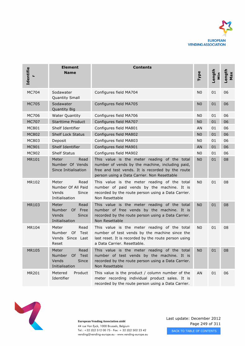
Last update: December 2012 Page 249 of 311
European Vending Association aisbl
44 rue Van Eyck, 1000 Brussels, Belgium Tel.: +32 (0)2 512 00 75 - Fax: + 32 (0)2 502 23 42 [email protected] - www.vending-europe.eu
Iden
tifi
er
Element Name
Contents
Typ
e
Len
gth
M
in
Len
gth
M
ax
MC704 Sodawater Quantity Small
Configures field MA704 N0 01 06
MC705 Sodawater Quantity Big
Configures field MA705 N0 01 06
MC706 Water Quantity Configures field MA706 N0 01 06
MC707 Starttime Product Configures field MA707 N0 01 06
MC801 Shelf Identifier Configures field MA801 AN 01 06
MC802 Shelf Lock Status Configures field MA802 N0 01 06
MC803 Deposit Configures field MA803 N0 01 06
MC901 Shelf Identifier Configures field MA901 AN 01 06
MC902 Shelf Status Configures field MA902 N0 01 06
MR101 Meter Read Number Of Vends Since Initialisation
This value is the meter reading of the total number of vends by the machine, including paid, free and test vends. It is recorded by the route person using a Data Carrier. Non Resettable
N0 01 08
MR102 Meter Read Number Of All Paid Vends Since Initialisation
This value is the meter reading of the total number of paid vends by the machine. It is recorded by the route person using a Data Carrier. Non Resettable
N0 01 08
MR103 Meter Read Number Of Free Vends Since Initialisation
This value is the meter reading of the total number of free vends by the machine. It is recorded by the route person using a Data Carrier. Non Resettable
N0 01 08
MR104 Meter Read Number Of Test Vends Since Last Reset
This value is the meter reading of the total number of test vends by the machine since the last reset. It is recorded by the route person using a Data Carrier. Resettable.
N0 01 08
MR105 Meter Read Number Of Test Vends Since Initialisation
This value is the meter reading of the total number of test vends by the machine. It is recorded by the route person using a Data Carrier. Non Resettable
N0 01 08
MR201 Metered Product Identifier
This value is the product / column number of the meter recording individual product sales. It is recorded by the route person using a Data Carrier.
AN 01 06
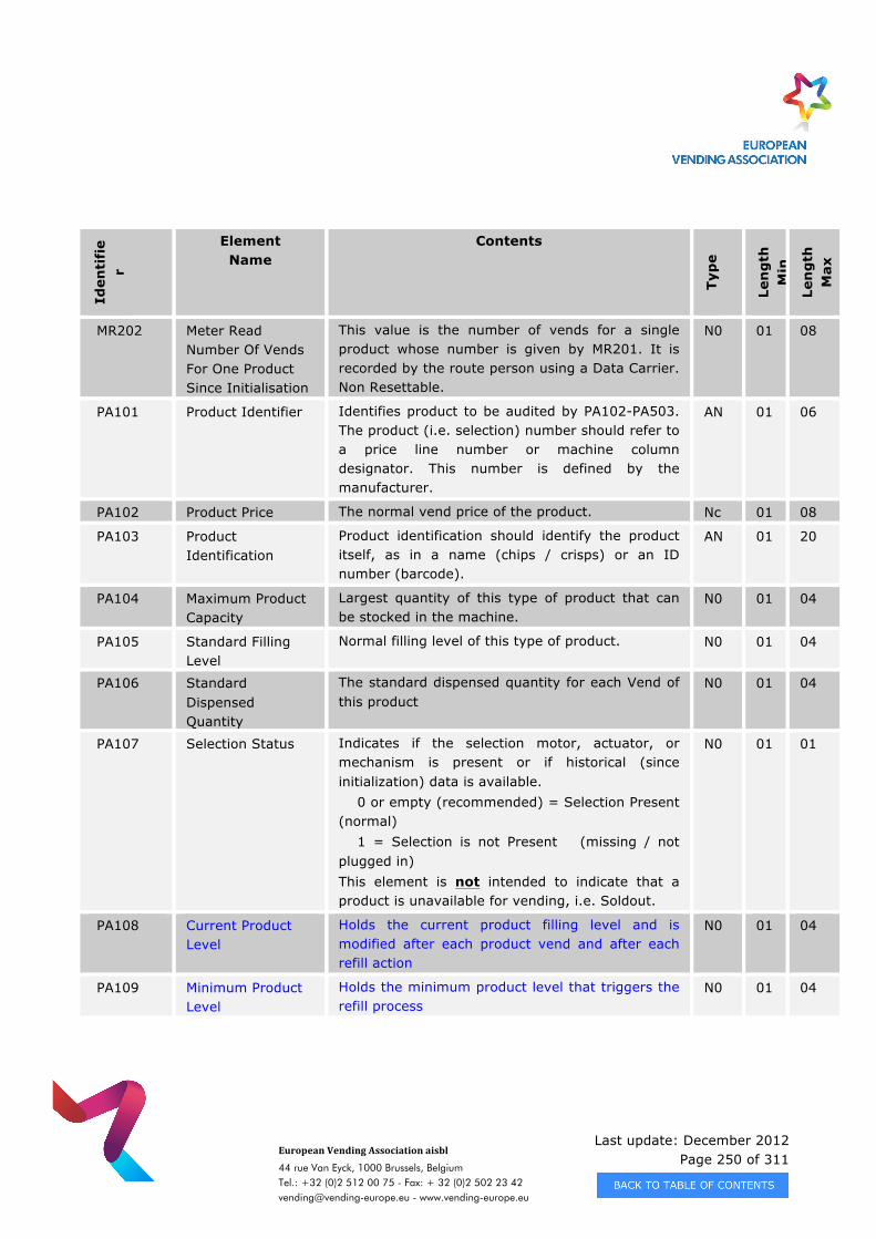
Last update: December 2012 Page 250 of 311
European Vending Association aisbl
44 rue Van Eyck, 1000 Brussels, Belgium Tel.: +32 (0)2 512 00 75 - Fax: + 32 (0)2 502 23 42 [email protected] - www.vending-europe.eu
Iden
tifi
er
Element Name
Contents
Typ
e
Len
gth
M
in
Len
gth
M
ax
MR202 Meter Read Number Of Vends For One Product Since Initialisation
This value is the number of vends for a single product whose number is given by MR201. It is recorded by the route person using a Data Carrier. Non Resettable.
N0 01 08
PA101 Product Identifier Identifies product to be audited by PA102-PA503. The product (i.e. selection) number should refer to a price line number or machine column designator. This number is defined by the manufacturer.
AN 01 06
PA102 Product Price The normal vend price of the product. Nc 01 08
PA103 Product Identification
Product identification should identify the product itself, as in a name (chips / crisps) or an ID number (barcode).
AN 01 20
PA104 Maximum Product Capacity
Largest quantity of this type of product that can be stocked in the machine.
N0 01 04
PA105 Standard Filling Level
Normal filling level of this type of product. N0 01 04
PA106 Standard Dispensed Quantity
The standard dispensed quantity for each Vend of this product
N0 01 04
PA107 Selection Status Indicates if the selection motor, actuator, or mechanism is present or if historical (since initialization) data is available. 0 or empty (recommended) = Selection Present (normal) 1 = Selection is not Present (missing / not plugged in) This element is not intended to indicate that a product is unavailable for vending, i.e. Soldout.
N0 01 01
PA108 Current Product Level
Holds the current product filling level and is modified after each product vend and after each refill action
N0 01 04
PA109 Minimum Product Level
Holds the minimum product level that triggers the refill process
N0 01 04
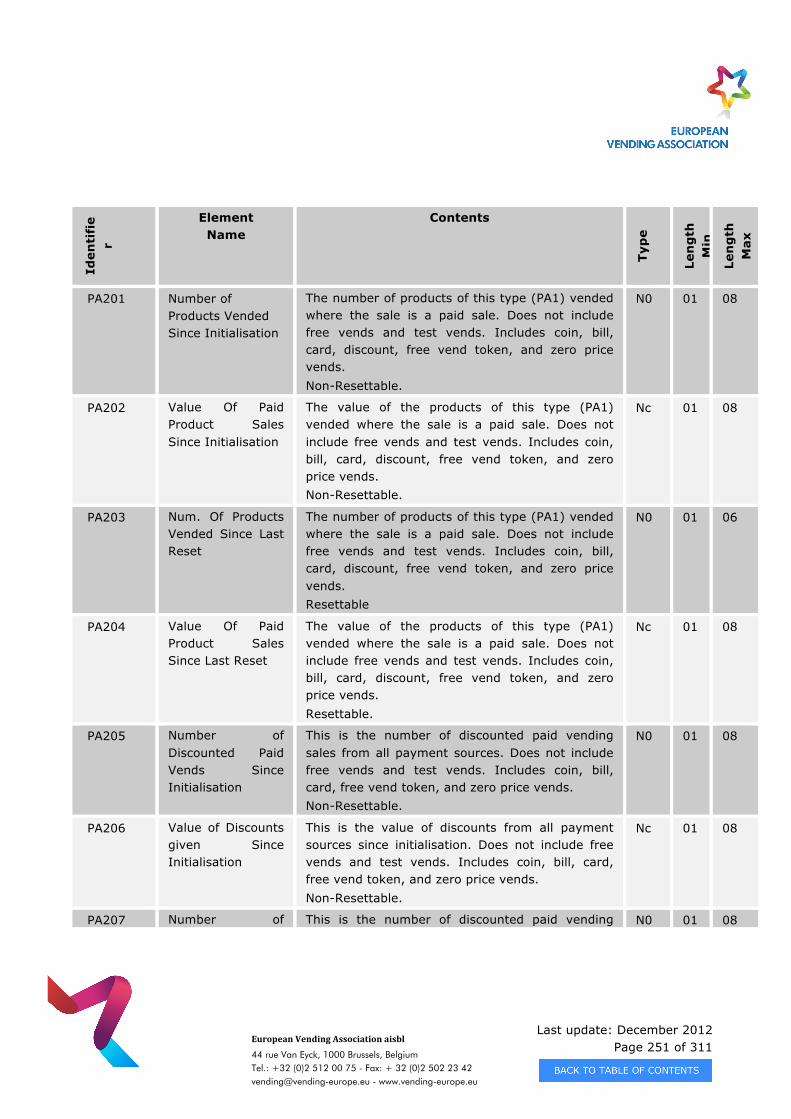
Last update: December 2012 Page 251 of 311
European Vending Association aisbl
44 rue Van Eyck, 1000 Brussels, Belgium Tel.: +32 (0)2 512 00 75 - Fax: + 32 (0)2 502 23 42 [email protected] - www.vending-europe.eu
Iden
tifi
er
Element Name
Contents
Typ
e
Len
gth
M
in
Len
gth
M
ax
PA201 Number of Products Vended Since Initialisation
The number of products of this type (PA1) vended where the sale is a paid sale. Does not include free vends and test vends. Includes coin, bill, card, discount, free vend token, and zero price vends. Non-Resettable.
N0 01 08
PA202 Value Of Paid Product Sales Since Initialisation
The value of the products of this type (PA1) vended where the sale is a paid sale. Does not include free vends and test vends. Includes coin, bill, card, discount, free vend token, and zero price vends. Non-Resettable.
Nc 01 08
PA203 Num. Of Products Vended Since Last Reset
The number of products of this type (PA1) vended where the sale is a paid sale. Does not include free vends and test vends. Includes coin, bill, card, discount, free vend token, and zero price vends. Resettable
N0 01 06
PA204 Value Of Paid Product Sales Since Last Reset
The value of the products of this type (PA1) vended where the sale is a paid sale. Does not include free vends and test vends. Includes coin, bill, card, discount, free vend token, and zero price vends. Resettable.
Nc 01 08
PA205 Number of Discounted Paid Vends Since Initialisation
This is the number of discounted paid vending sales from all payment sources. Does not include free vends and test vends. Includes coin, bill, card, free vend token, and zero price vends. Non-Resettable.
N0 01 08
PA206 Value of Discounts given Since Initialisation
This is the value of discounts from all payment sources since initialisation. Does not include free vends and test vends. Includes coin, bill, card, free vend token, and zero price vends. Non-Resettable.
Nc 01 08
PA207 Number of This is the number of discounted paid vending N0 01 08
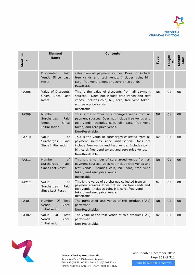
Last update: December 2012 Page 252 of 311
European Vending Association aisbl
44 rue Van Eyck, 1000 Brussels, Belgium Tel.: +32 (0)2 512 00 75 - Fax: + 32 (0)2 502 23 42 [email protected] - www.vending-europe.eu
Iden
tifi
er
Element Name
Contents
Typ
e
Len
gth
M
in
Len
gth
M
ax
Discounted Paid Vends Since Last Reset
sales from all payment sources. Does not include free vends and test vends. Includes coin, bill, card, free vend token, and zero price vends. Resettable.
PA208 Value of Discounts Given Since Last Reset
This is the value of discounts from all payment sources. Does not include free vends and test vends. Includes coin, bill, card, free vend token, and zero price vends. Resettable.
Nc 01 08
PA209 Number of Surcharges Paid Vends Since Initialisation
This is the number of surcharged vends from all payment sources. Does not include free vends and test vends. Includes coin, bill, card, free vend token, and zero price vends. Non-Resettable.
N0 01 08
PA210 Value of Surcharges Paid Since Initialisation
This is the value of surcharges collected from all payment sources since initialisation. Does not include free vends and test vends. Includes coin, bill, card, free vend token, and zero price vends. Non-Resettable.
Nc 01 08
PA211 Number of Surcharged Paid Since Last Reset
This is the number of surcharged vends from all payment sources. Does not include free vends and test vends. Includes coin, bill, card, free vend token, and zero price vends. Resettable.
N0 01 06
PA212 Value of Surcharges Paid Since Last Reset
This is the value of surcharges collected from all payment sources. Does not include free vends and test vends. Includes coin, bill, card, free vend token, and zero price vends. Resettable.
Nc 01 08
PA301 Number Of Test Vends Since Initialisation
The number of test vends of this product (PA1) performed. Non-Resettable.
N0 01 08
PA302 Value Of Test Vends Since Initialisation
The value of the test vends of this product (PA1) performed. Non-Resettable.
Nc 01 08
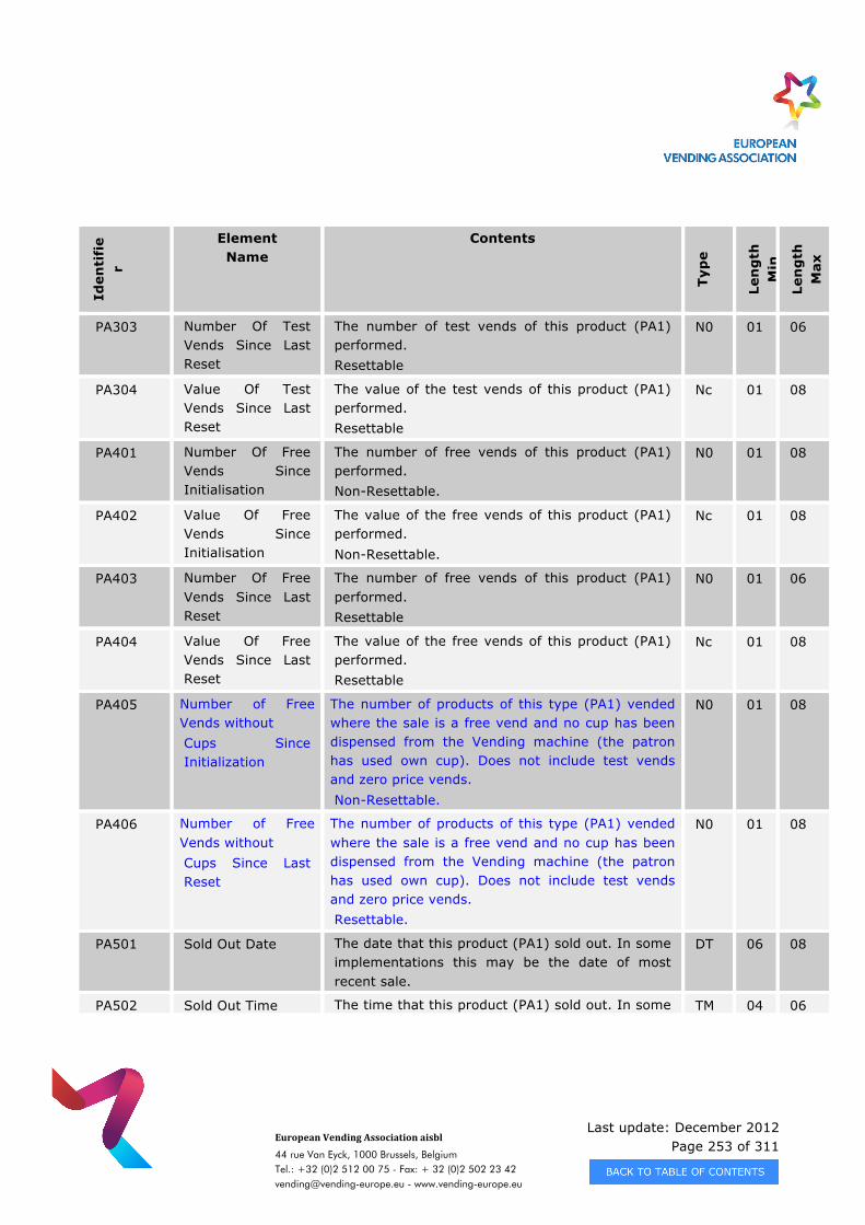
Last update: December 2012 Page 253 of 311
European Vending Association aisbl
44 rue Van Eyck, 1000 Brussels, Belgium Tel.: +32 (0)2 512 00 75 - Fax: + 32 (0)2 502 23 42 [email protected] - www.vending-europe.eu
Iden
tifi
er
Element Name
Contents
Typ
e
Len
gth
M
in
Len
gth
M
ax
PA303 Number Of Test Vends Since Last Reset
The number of test vends of this product (PA1) performed. Resettable
N0 01 06
PA304 Value Of Test Vends Since Last Reset
The value of the test vends of this product (PA1) performed. Resettable
Nc 01 08
PA401 Number Of Free Vends Since Initialisation
The number of free vends of this product (PA1) performed. Non-Resettable.
N0 01 08
PA402 Value Of Free Vends Since Initialisation
The value of the free vends of this product (PA1) performed. Non-Resettable.
Nc 01 08
PA403 Number Of Free Vends Since Last Reset
The number of free vends of this product (PA1) performed. Resettable
N0 01 06
PA404 Value Of Free Vends Since Last Reset
The value of the free vends of this product (PA1) performed. Resettable
Nc 01 08
PA405 Number of Free Vends without Cups Since Initialization
The number of products of this type (PA1) vended where the sale is a free vend and no cup has been dispensed from the Vending machine (the patron has used own cup). Does not include test vends and zero price vends. Non-Resettable.
N0 01 08
PA406 Number of Free Vends without Cups Since Last Reset
The number of products of this type (PA1) vended where the sale is a free vend and no cup has been dispensed from the Vending machine (the patron has used own cup). Does not include test vends and zero price vends. Resettable.
N0 01 08
PA501 Sold Out Date The date that this product (PA1) sold out. In some implementations this may be the date of most recent sale.
DT 06 08
PA502 Sold Out Time The time that this product (PA1) sold out. In some TM 04 06
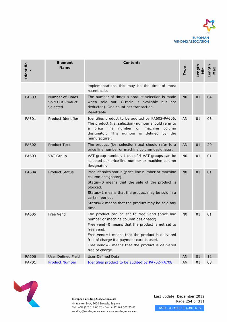
Last update: December 2012 Page 254 of 311
European Vending Association aisbl
44 rue Van Eyck, 1000 Brussels, Belgium Tel.: +32 (0)2 512 00 75 - Fax: + 32 (0)2 502 23 42 [email protected] - www.vending-europe.eu
Iden
tifi
er
Element Name
Contents
Typ
e
Len
gth
M
in
Len
gth
M
ax
implementations this may be the time of most recent sale.
PA503 Number of Times Sold Out Product Selected
The number of times a product selection is made when sold out. (Credit is available but not deducted). One count per transaction. Resettable
N0 01 04
PA601 Product Identifier Identifies product to be audited by PA602-PA606. The product (i.e. selection) number should refer to a price line number or machine column designator. This number is defined by the manufacturer.
AN 01 06
PA602 Product Text The product (i.e. selection) text should refer to a price line number or machine column designator.
AN 01 20
PA603 VAT Group VAT group number. 1 out of 4 VAT groups can be selected per price line number or machine column designator.
N0 01 01
PA604 Product Status Product sales status (price line number or machine column designator). Status=0 means that the sale of the product is blocked. Status=1 means that the product may be sold in a certain period. Status=2 means that the product may be sold any time.
N0 01 01
PA605 Free Vend The product can be set to free vend (price line number or machine column designator). Free vend=0 means that the product is not set to free vend. Free vend=1 means that the product is delivered free of charge if a payment card is used. Free vend=2 means that the product is delivered free of charge.
N0 01 01
PA606 User Defined Field User Defined Data AN 01 12
PA701 Product Number Identifies product to be audited by PA702-PA708. AN 01 08
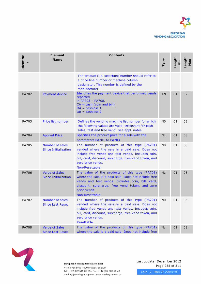
Last update: December 2012 Page 255 of 311
European Vending Association aisbl
44 rue Van Eyck, 1000 Brussels, Belgium Tel.: +32 (0)2 512 00 75 - Fax: + 32 (0)2 502 23 42 [email protected] - www.vending-europe.eu
Iden
tifi
er
Element Name
Contents
Typ
e
Len
gth
M
in
Len
gth
M
ax
The product (i.e. selection) number should refer to a price line number or machine column designator. This number is defined by the manufacturer.
PA702 Payment device Identifies the payment device that performed vends reported in PA703 – PA708. CA = cash (coin and bill) DA = cashless 1 DB = cashless 2 …
AN 01 02
PA703 Price list number Defines the vending machine list number for which the following values are valid. Irrelevant for cash sales, test and free vend. See appl. notes.
N0 01 03
PA704 Applied Price Specifies the product price for a sale with the parameters PA701 to PA703
Nc 01 08
PA705 Number of sales Since Initialization
The number of products of this type (PA701) vended where the sale is a paid sale. Does not include free vends and test vends. Includes coin, bill, card, discount, surcharge, free vend token, and zero price vends. Non-Resettable.
N0 01 08
PA706 Value of Sales Since Initialization
The value of the products of this type (PA701) where the sale is a paid sale. Does not include free vends and test vends. Includes coin, bill, card, discount, surcharge, free vend token, and zero price vends. Non-Resettable.
Nc 01 08
PA707 Number of sales Since Last Reset
The number of products of this type (PA701) vended where the sale is a paid sale. Does not include free vends and test vends. Includes coin, bill, card, discount, surcharge, free vend token, and zero price vends. Resettable.
N0 01 06
PA708 Value of Sales Since Last Reset
The value of the products of this type (PA701) where the sale is a paid sale. Does not include free
Nc 01 08
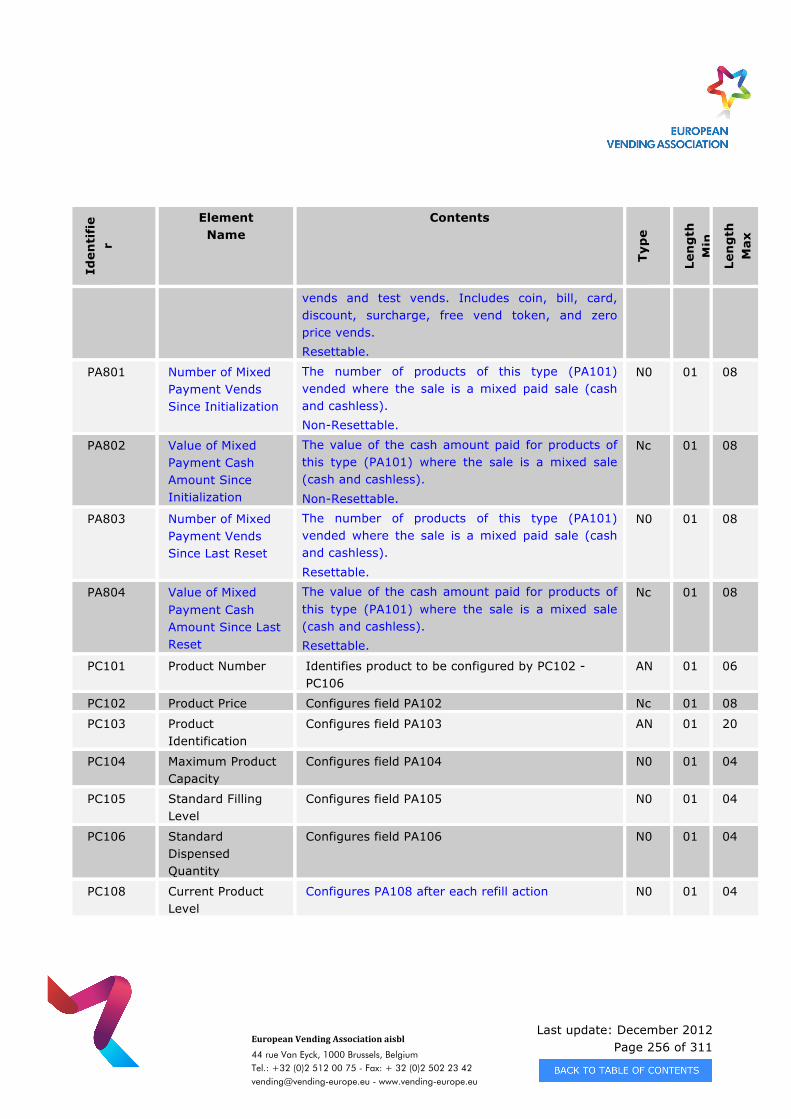
Last update: December 2012 Page 256 of 311
European Vending Association aisbl
44 rue Van Eyck, 1000 Brussels, Belgium Tel.: +32 (0)2 512 00 75 - Fax: + 32 (0)2 502 23 42 [email protected] - www.vending-europe.eu
Iden
tifi
er
Element Name
Contents
Typ
e
Len
gth
M
in
Len
gth
M
ax
vends and test vends. Includes coin, bill, card, discount, surcharge, free vend token, and zero price vends. Resettable.
PA801 Number of Mixed Payment Vends Since Initialization
The number of products of this type (PA101) vended where the sale is a mixed paid sale (cash and cashless). Non-Resettable.
N0 01 08
PA802 Value of Mixed Payment Cash Amount Since Initialization
The value of the cash amount paid for products of this type (PA101) where the sale is a mixed sale (cash and cashless). Non-Resettable.
Nc 01 08
PA803 Number of Mixed Payment Vends Since Last Reset
The number of products of this type (PA101) vended where the sale is a mixed paid sale (cash and cashless). Resettable.
N0 01 08
PA804 Value of Mixed Payment Cash Amount Since Last Reset
The value of the cash amount paid for products of this type (PA101) where the sale is a mixed sale (cash and cashless). Resettable.
Nc 01 08
PC101 Product Number Identifies product to be configured by PC102 - PC106
AN 01 06
PC102 Product Price Configures field PA102 Nc 01 08
PC103 Product Identification
Configures field PA103 AN 01 20
PC104 Maximum Product Capacity
Configures field PA104 N0 01 04
PC105 Standard Filling Level
Configures field PA105 N0 01 04
PC106 Standard Dispensed Quantity
Configures field PA106 N0 01 04
PC108 Current Product Level
Configures PA108 after each refill action N0 01 04
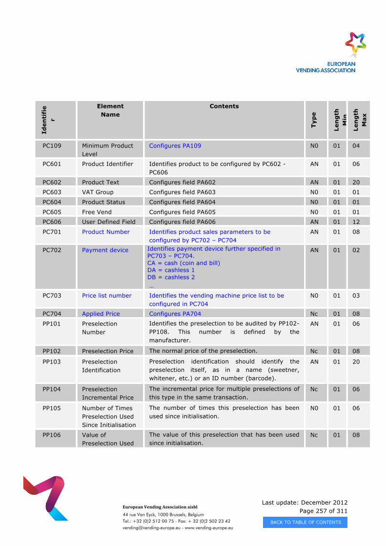
Last update: December 2012 Page 257 of 311
European Vending Association aisbl
44 rue Van Eyck, 1000 Brussels, Belgium Tel.: +32 (0)2 512 00 75 - Fax: + 32 (0)2 502 23 42 [email protected] - www.vending-europe.eu
Iden
tifi
er
Element Name
Contents
Typ
e
Len
gth
M
in
Len
gth
M
ax
PC109 Minimum Product Level
Configures PA109 N0 01 04
PC601 Product Identifier Identifies product to be configured by PC602 - PC606
AN 01 06
PC602 Product Text Configures field PA602 AN 01 20
PC603 VAT Group Configures field PA603 N0 01 01
PC604 Product Status Configures field PA604 N0 01 01
PC605 Free Vend Configures field PA605 N0 01 01
PC606 User Defined Field Configures field PA606 AN 01 12
PC701 Product Number Identifies product sales parameters to be configured by PC702 – PC704
AN 01 08
PC702 Payment device Identifies payment device further specified in PC703 – PC704. CA = cash (coin and bill) DA = cashless 1 DB = cashless 2 …
AN 01 02
PC703 Price list number Identifies the vending machine price list to be configured in PC704
N0 01 03
PC704 Applied Price Configures PA704 Nc 01 08
PP101 Preselection Number
Identifies the preselection to be audited by PP102-PP108. This number is defined by the manufacturer.
AN 01 06
PP102 Preselection Price The normal price of the preselection. Nc 01 08
PP103 Preselection Identification
Preselection identification should identify the preselection itself, as in a name (sweetner, whitener, etc.) or an ID number (barcode).
AN 01 20
PP104 Preselection Incremental Price
The incremental price for multiple preselections of this type in the same transaction.
Nc 01 06
PP105 Number of Times Preselection Used Since Initialisation
The number of times this preselection has been used since initialisation.
N0 01 06
PP106 Value of Preselection Used
The value of this preselection that has been used since initialisation.
Nc 01 08
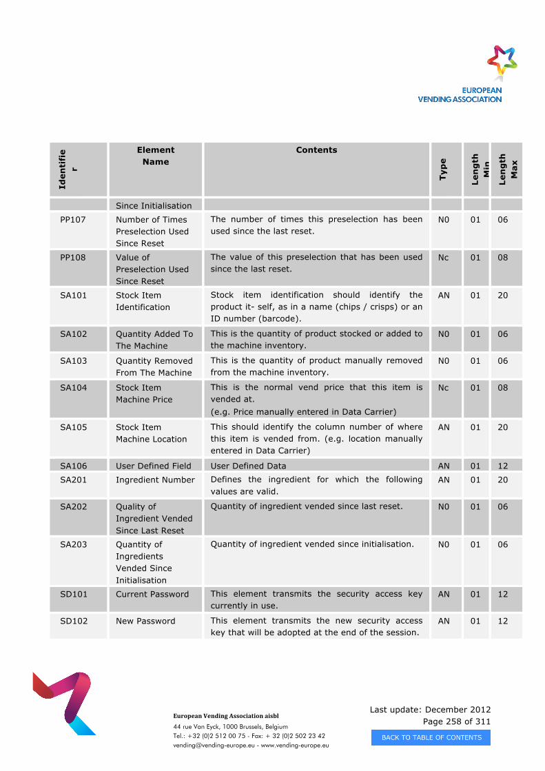
Last update: December 2012 Page 258 of 311
European Vending Association aisbl
44 rue Van Eyck, 1000 Brussels, Belgium Tel.: +32 (0)2 512 00 75 - Fax: + 32 (0)2 502 23 42 [email protected] - www.vending-europe.eu
Iden
tifi
er
Element Name
Contents
Typ
e
Len
gth
M
in
Len
gth
M
ax
Since Initialisation
PP107 Number of Times Preselection Used Since Reset
The number of times this preselection has been used since the last reset.
N0 01 06
PP108 Value of Preselection Used Since Reset
The value of this preselection that has been used since the last reset.
Nc 01 08
SA101 Stock Item Identification
Stock item identification should identify the product it- self, as in a name (chips / crisps) or an ID number (barcode).
AN 01 20
SA102 Quantity Added To The Machine
This is the quantity of product stocked or added to the machine inventory.
N0 01 06
SA103 Quantity Removed From The Machine
This is the quantity of product manually removed from the machine inventory.
N0 01 06
SA104 Stock Item Machine Price
This is the normal vend price that this item is vended at. (e.g. Price manually entered in Data Carrier)
Nc 01 08
SA105 Stock Item Machine Location
This should identify the column number of where this item is vended from. (e.g. location manually entered in Data Carrier)
AN 01 20
SA106 User Defined Field User Defined Data AN 01 12
SA201 Ingredient Number Defines the ingredient for which the following values are valid.
AN 01 20
SA202 Quality of Ingredient Vended Since Last Reset
Quantity of ingredient vended since last reset. N0 01 06
SA203 Quantity of Ingredients Vended Since Initialisation
Quantity of ingredient vended since initialisation. N0 01 06
SD101 Current Password This element transmits the security access key currently in use.
AN 01 12
SD102 New Password This element transmits the new security access key that will be adopted at the end of the session.
AN 01 12
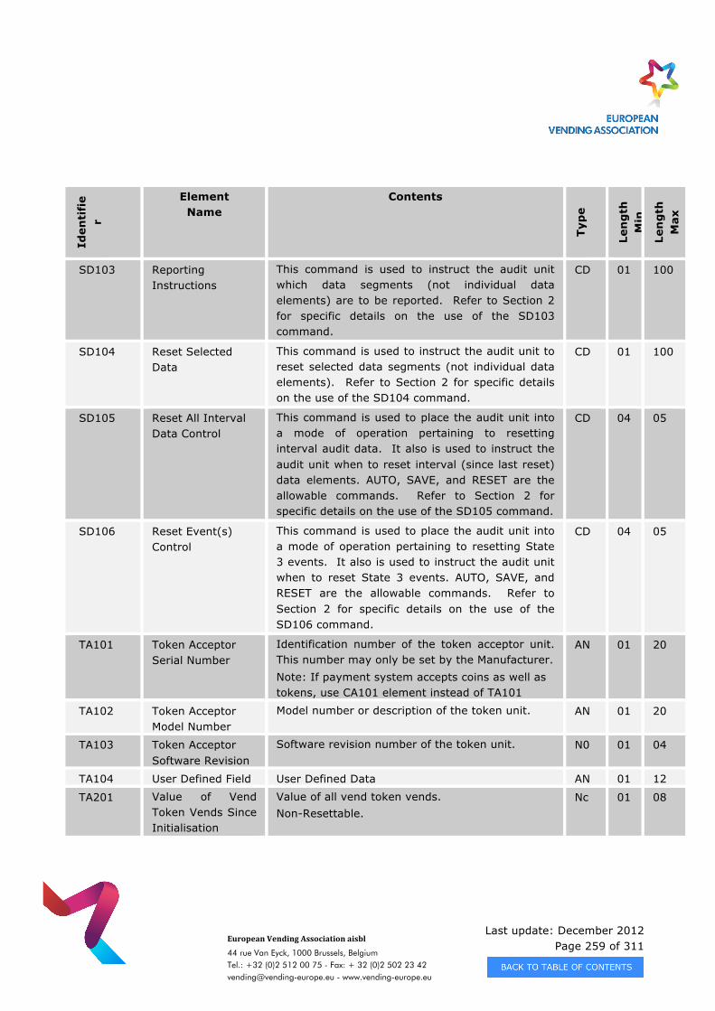
Last update: December 2012 Page 259 of 311
European Vending Association aisbl
44 rue Van Eyck, 1000 Brussels, Belgium Tel.: +32 (0)2 512 00 75 - Fax: + 32 (0)2 502 23 42 [email protected] - www.vending-europe.eu
Iden
tifi
er
Element Name
Contents
Typ
e
Len
gth
M
in
Len
gth
M
ax
SD103 Reporting Instructions
This command is used to instruct the audit unit which data segments (not individual data elements) are to be reported. Refer to Section 2 for specific details on the use of the SD103 command.
CD 01 100
SD104 Reset Selected Data
This command is used to instruct the audit unit to reset selected data segments (not individual data elements). Refer to Section 2 for specific details on the use of the SD104 command.
CD 01 100
SD105 Reset All Interval Data Control
This command is used to place the audit unit into a mode of operation pertaining to resetting interval audit data. It also is used to instruct the audit unit when to reset interval (since last reset) data elements. AUTO, SAVE, and RESET are the allowable commands. Refer to Section 2 for specific details on the use of the SD105 command.
CD 04 05
SD106 Reset Event(s) Control
This command is used to place the audit unit into a mode of operation pertaining to resetting State 3 events. It also is used to instruct the audit unit when to reset State 3 events. AUTO, SAVE, and RESET are the allowable commands. Refer to Section 2 for specific details on the use of the SD106 command.
CD 04 05
TA101 Token Acceptor Serial Number
Identification number of the token acceptor unit. This number may only be set by the Manufacturer. Note: If payment system accepts coins as well as tokens, use CA101 element instead of TA101
AN 01 20
TA102 Token Acceptor Model Number
Model number or description of the token unit. AN 01 20
TA103 Token Acceptor Software Revision
Software revision number of the token unit. N0 01 04
TA104 User Defined Field User Defined Data AN 01 12
TA201 Value of Vend Token Vends Since Initialisation
Value of all vend token vends. Non-Resettable.
Nc 01 08

Last update: December 2012 Page 260 of 311
European Vending Association aisbl
44 rue Van Eyck, 1000 Brussels, Belgium Tel.: +32 (0)2 512 00 75 - Fax: + 32 (0)2 502 23 42 [email protected] - www.vending-europe.eu
Iden
tifi
er
Element Name
Contents
Typ
e
Len
gth
M
in
Len
gth
M
ax
TA202 No. of Vend Token Vends Since Initialisation
Number of all vend token vends Non-Resettable.
N0 01 08
TA203 Value of Vend Token Sales Since Last Reset
Value of all vend token sales. Resettable.
Nc 01 06
TA204 No. of Vend Token Sales Since Last Reset
Number of all vend token sales. Resettable.
N0 01 06
TA205 Value of Value Token Since Initialisation
Value of all value token sales. Non-Resettable.
Nc 01 08
TA206 No. of Value Token Since Initialisation
Number of all value token sales. Non-Resettable.
N0 01 08
TA207 Value of Value Token Sales Since Last Reset
Value of all value token sales. Resettable.
Nc 01 06
TA208 No. of Value Token Vends Since Last Reset
Number of all value token sales. Resettable.
N0 01 06
TA301 Value of Value Tokens In Since Last Reset
Value of all value tokens accepted. Resettable.
Nc 01 08
TA302 Value of Value Tokens In Since Initialisation
Value of all value tokens. Non-Resettable.
Nc 01 08
TA401 Value of Value Tokens Dispensed Since Last Reset
Value of all value tokens dispensed as change plus manually dispensed. Resettable.
Nc 01 08
TA402 Value of Value Tokens Manually Dispensed Since Last Reset
Value of all value tokens manually dispensed. Resettable.
Nc 01 08
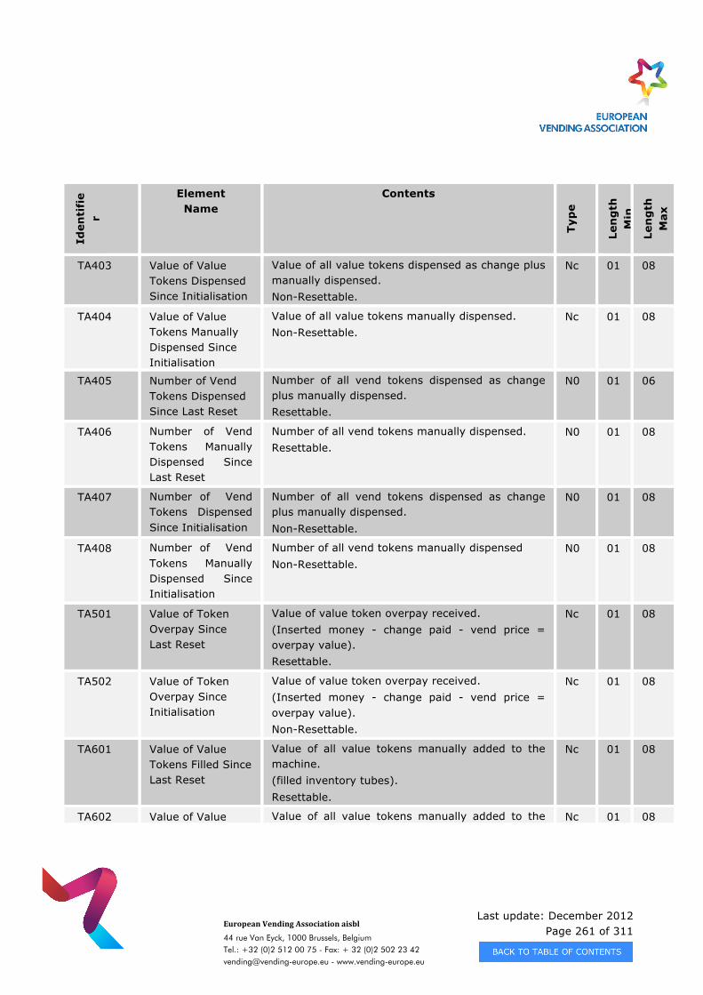
Last update: December 2012 Page 261 of 311
European Vending Association aisbl
44 rue Van Eyck, 1000 Brussels, Belgium Tel.: +32 (0)2 512 00 75 - Fax: + 32 (0)2 502 23 42 [email protected] - www.vending-europe.eu
Iden
tifi
er
Element Name
Contents
Typ
e
Len
gth
M
in
Len
gth
M
ax
TA403 Value of Value Tokens Dispensed Since Initialisation
Value of all value tokens dispensed as change plus manually dispensed. Non-Resettable.
Nc 01 08
TA404 Value of Value Tokens Manually Dispensed Since Initialisation
Value of all value tokens manually dispensed. Non-Resettable.
Nc 01 08
TA405 Number of Vend Tokens Dispensed Since Last Reset
Number of all vend tokens dispensed as change plus manually dispensed. Resettable.
N0 01 06
TA406 Number of Vend Tokens Manually Dispensed Since Last Reset
Number of all vend tokens manually dispensed. Resettable.
N0 01 08
TA407 Number of Vend Tokens Dispensed Since Initialisation
Number of all vend tokens dispensed as change plus manually dispensed. Non-Resettable.
N0 01 08
TA408 Number of Vend Tokens Manually Dispensed Since Initialisation
Number of all vend tokens manually dispensed Non-Resettable.
N0 01 08
TA501 Value of Token Overpay Since Last Reset
Value of value token overpay received. (Inserted money - change paid - vend price = overpay value). Resettable.
Nc 01 08
TA502 Value of Token Overpay Since Initialisation
Value of value token overpay received. (Inserted money - change paid - vend price = overpay value). Non-Resettable.
Nc 01 08
TA601 Value of Value Tokens Filled Since Last Reset
Value of all value tokens manually added to the machine. (filled inventory tubes). Resettable.
Nc 01 08
TA602 Value of Value Value of all value tokens manually added to the Nc 01 08
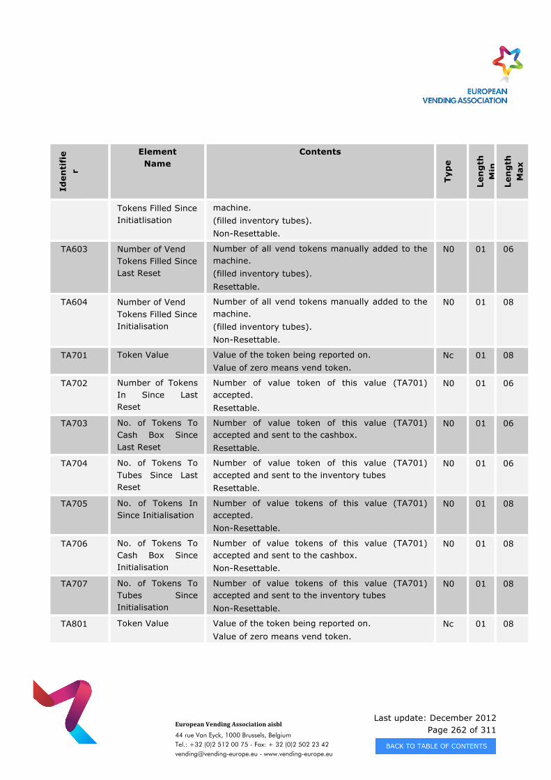
Last update: December 2012 Page 262 of 311
European Vending Association aisbl
44 rue Van Eyck, 1000 Brussels, Belgium Tel.: +32 (0)2 512 00 75 - Fax: + 32 (0)2 502 23 42 [email protected] - www.vending-europe.eu
Iden
tifi
er
Element Name
Contents
Typ
e
Len
gth
M
in
Len
gth
M
ax
Tokens Filled Since Initiatlisation
machine. (filled inventory tubes). Non-Resettable.
TA603 Number of Vend Tokens Filled Since Last Reset
Number of all vend tokens manually added to the machine. (filled inventory tubes). Resettable.
N0 01 06
TA604 Number of Vend Tokens Filled Since Initialisation
Number of all vend tokens manually added to the machine. (filled inventory tubes). Non-Resettable.
N0 01 08
TA701 Token Value Value of the token being reported on. Value of zero means vend token.
Nc 01 08
TA702 Number of Tokens In Since Last Reset
Number of value token of this value (TA701) accepted. Resettable.
N0 01 06
TA703 No. of Tokens To Cash Box Since Last Reset
Number of value token of this value (TA701) accepted and sent to the cashbox. Resettable.
N0 01 06
TA704 No. of Tokens To Tubes Since Last Reset
Number of value token of this value (TA701) accepted and sent to the inventory tubes Resettable.
N0 01 06
TA705 No. of Tokens In Since Initialisation
Number of value tokens of this value (TA701) accepted. Non-Resettable.
N0 01 08
TA706 No. of Tokens To Cash Box Since Initialisation
Number of value tokens of this value (TA701) accepted and sent to the cashbox. Non-Resettable.
N0 01 08
TA707 No. of Tokens To Tubes Since Initialisation
Number of value tokens of this value (TA701) accepted and sent to the inventory tubes Non-Resettable.
N0 01 08
TA801 Token Value Value of the token being reported on. Value of zero means vend token.
Nc 01 08
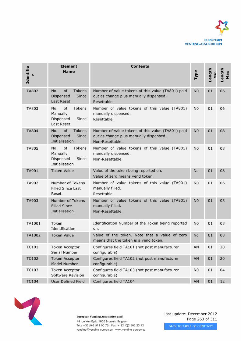
Last update: December 2012 Page 263 of 311
European Vending Association aisbl
44 rue Van Eyck, 1000 Brussels, Belgium Tel.: +32 (0)2 512 00 75 - Fax: + 32 (0)2 502 23 42 [email protected] - www.vending-europe.eu
Iden
tifi
er
Element Name
Contents
Typ
e
Len
gth
M
in
Len
gth
M
ax
TA802 No. of Tokens Dispensed Since Last Reset
Number of value tokens of this value (TA801) paid out as change plus manually dispensed. Resettable.
N0 01 06
TA803 No. of Tokens Manually Dispensed Since Last Reset
Number of value tokens of this value (TA801) manually dispensed. Resettable.
N0 01 06
TA804 No. of Tokens Dispensed Since Initialisation
Number of value tokens of this value (TA801) paid out as change plus manually dispensed. Non-Resettable.
N0 01 08
TA805 No. of Tokens Manually Dispensed Since Initialisation
Number of value tokens of this value (TA801) manually dispensed. Non-Resettable.
N0 01 08
TA901 Token Value Value of the token being reported on. Value of zero means vend token.
Nc 01 08
TA902 Number of Tokens Filled Since Last Reset
Number of value tokens of this value (TA901) manually filled. Resettable.
N0 01 06
TA903 Number of Tokens Filled Since Initialisation
Number of value tokens of this value (TA901) manually filled. Non-Resettable.
N0 01 08
TA1001 Token Identification
Identification Number of the Token being reported on.
N0 01 08
TA1002 Token Value Value of the token. Note that a value of zero means that the token is a vend token.
Nc 01 08
TC101 Token Acceptor Serial Number
Configures field TA101 (not post manufacturer configurable)
AN 01 20
TC102 Token Acceptor Model Number
Configures field TA102 (not post manufacturer configurable)
AN 01 20
TC103 Token Acceptor Software Revision
Configures field TA103 (not post manufacturer configurable)
N0 01 04
TC104 User Defined Field Configures field TA104 AN 01 12
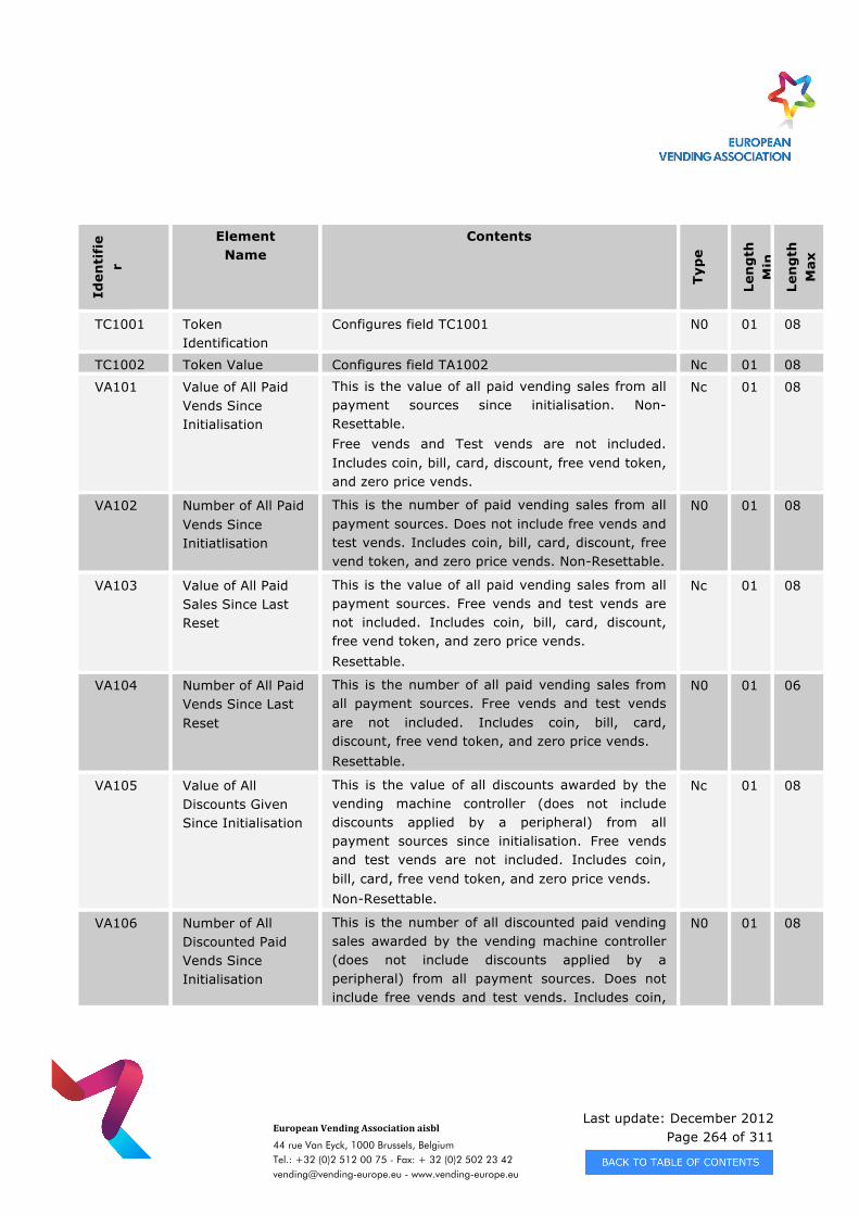
Last update: December 2012 Page 264 of 311
European Vending Association aisbl
44 rue Van Eyck, 1000 Brussels, Belgium Tel.: +32 (0)2 512 00 75 - Fax: + 32 (0)2 502 23 42 [email protected] - www.vending-europe.eu
Iden
tifi
er
Element Name
Contents
Typ
e
Len
gth
M
in
Len
gth
M
ax
TC1001 Token Identification
Configures field TC1001 N0 01 08
TC1002 Token Value Configures field TA1002 Nc 01 08
VA101 Value of All Paid Vends Since Initialisation
This is the value of all paid vending sales from all payment sources since initialisation. Non-Resettable. Free vends and Test vends are not included. Includes coin, bill, card, discount, free vend token, and zero price vends.
Nc 01 08
VA102 Number of All Paid Vends Since Initiatlisation
This is the number of paid vending sales from all payment sources. Does not include free vends and test vends. Includes coin, bill, card, discount, free vend token, and zero price vends. Non-Resettable.
N0 01 08
VA103 Value of All Paid Sales Since Last Reset
This is the value of all paid vending sales from all payment sources. Free vends and test vends are not included. Includes coin, bill, card, discount, free vend token, and zero price vends. Resettable.
Nc 01 08
VA104 Number of All Paid Vends Since Last Reset
This is the number of all paid vending sales from all payment sources. Free vends and test vends are not included. Includes coin, bill, card, discount, free vend token, and zero price vends. Resettable.
N0 01 06
VA105 Value of All Discounts Given Since Initialisation
This is the value of all discounts awarded by the vending machine controller (does not include discounts applied by a peripheral) from all payment sources since initialisation. Free vends and test vends are not included. Includes coin, bill, card, free vend token, and zero price vends. Non-Resettable.
Nc 01 08
VA106 Number of All Discounted Paid Vends Since Initialisation
This is the number of all discounted paid vending sales awarded by the vending machine controller (does not include discounts applied by a peripheral) from all payment sources. Does not include free vends and test vends. Includes coin,
N0 01 08
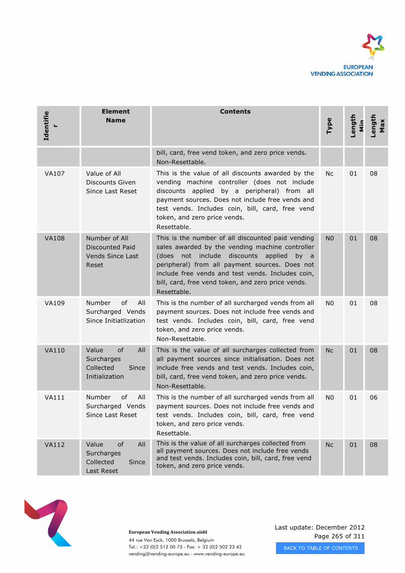
Last update: December 2012 Page 265 of 311
European Vending Association aisbl
44 rue Van Eyck, 1000 Brussels, Belgium Tel.: +32 (0)2 512 00 75 - Fax: + 32 (0)2 502 23 42 [email protected] - www.vending-europe.eu
Iden
tifi
er
Element Name
Contents
Typ
e
Len
gth
M
in
Len
gth
M
ax
bill, card, free vend token, and zero price vends. Non-Resettable.
VA107 Value of All Discounts Given Since Last Reset
This is the value of all discounts awarded by the vending machine controller (does not include discounts applied by a peripheral) from all payment sources. Does not include free vends and test vends. Includes coin, bill, card, free vend token, and zero price vends. Resettable.
Nc 01 08
VA108 Number of All Discounted Paid Vends Since Last Reset
This is the number of all discounted paid vending sales awarded by the vending machine controller (does not include discounts applied by a peripheral) from all payment sources. Does not include free vends and test vends. Includes coin, bill, card, free vend token, and zero price vends. Resettable.
N0 01 08
VA109 Number of All Surcharged Vends Since Initiatlization
This is the number of all surcharged vends from all payment sources. Does not include free vends and test vends. Includes coin, bill, card, free vend token, and zero price vends. Non-Resettable.
N0 01 08
VA110 Value of All Surcharges Collected Since Initialization
This is the value of all surcharges collected from all payment sources since initialisation. Does not include free vends and test vends. Includes coin, bill, card, free vend token, and zero price vends. Non-Resettable.
Nc 01 08
VA111 Number of All Surcharged Vends Since Last Reset
This is the number of all surcharged vends from all payment sources. Does not include free vends and test vends. Includes coin, bill, card, free vend token, and zero price vends. Resettable.
N0 01 06
VA112 Value of All Surcharges Collected Since Last Reset
This is the value of all surcharges collected from all payment sources. Does not include free vends and test vends. Includes coin, bill, card, free vend token, and zero price vends.
Nc 01 08
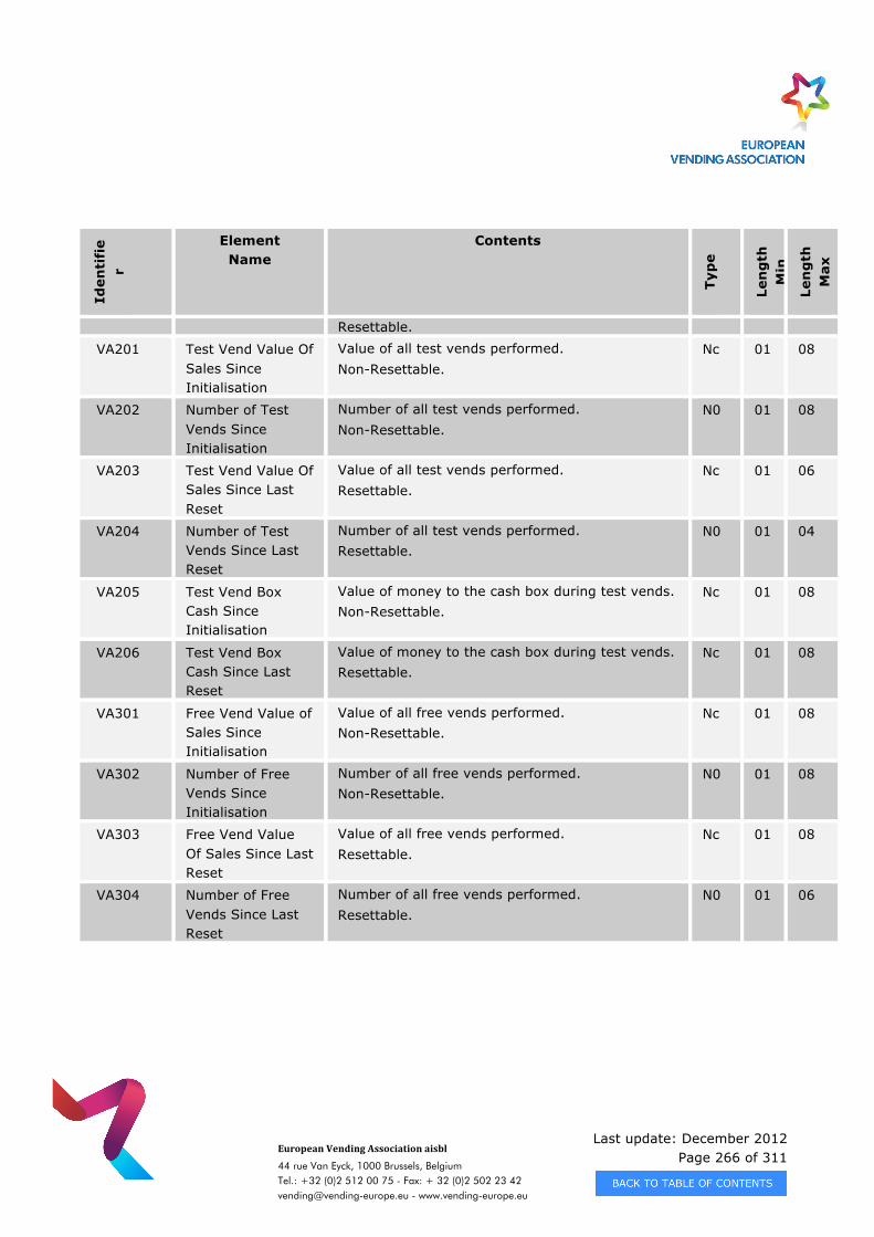
Last update: December 2012 Page 266 of 311
European Vending Association aisbl
44 rue Van Eyck, 1000 Brussels, Belgium Tel.: +32 (0)2 512 00 75 - Fax: + 32 (0)2 502 23 42 [email protected] - www.vending-europe.eu
Iden
tifi
er
Element Name
Contents
Typ
e
Len
gth
M
in
Len
gth
M
ax
Resettable.
VA201 Test Vend Value Of Sales Since Initialisation
Value of all test vends performed. Non-Resettable.
Nc 01 08
VA202 Number of Test Vends Since Initialisation
Number of all test vends performed. Non-Resettable.
N0 01 08
VA203 Test Vend Value Of Sales Since Last Reset
Value of all test vends performed. Resettable.
Nc 01 06
VA204 Number of Test Vends Since Last Reset
Number of all test vends performed. Resettable.
N0 01 04
VA205 Test Vend Box Cash Since Initialisation
Value of money to the cash box during test vends. Non-Resettable.
Nc 01 08
VA206 Test Vend Box Cash Since Last Reset
Value of money to the cash box during test vends. Resettable.
Nc 01 08
VA301 Free Vend Value of Sales Since Initialisation
Value of all free vends performed. Non-Resettable.
Nc 01 08
VA302 Number of Free Vends Since Initialisation
Number of all free vends performed. Non-Resettable.
N0 01 08
VA303 Free Vend Value Of Sales Since Last Reset
Value of all free vends performed. Resettable.
Nc 01 08
VA304 Number of Free Vends Since Last Reset
Number of all free vends performed. Resettable.
N0 01 06
Last update: December 2012 Page 267 of 311
European Vending Association aisbl
44 rue Van Eyck, 1000 Brussels, Belgium Tel.: +32 (0)2 512 00 75 - Fax: + 32 (0)2 502 23 42 [email protected] - www.vending-europe.eu
APPENDIX B - MANUFACTURER CODES
In order to ensure that the Serial Numbering of products does not produce equipment with duplicate numbers, e.g. Two coin mechanisms both serial number 123, or a Vend-ing Machine Control board and a Coin Mechanism both serial number 456, it has been agreed to prefix serial numbers (and fault codes where they do not conform to the standard code) with a three letter manufacturer specific code. The following codes have been reserved for use. The table below lists the reserved manufacturer codes at the publication date of EVA DTS 6.1. The full list of current manufacturer codes is available on the EVA website www.vending-europe.eu
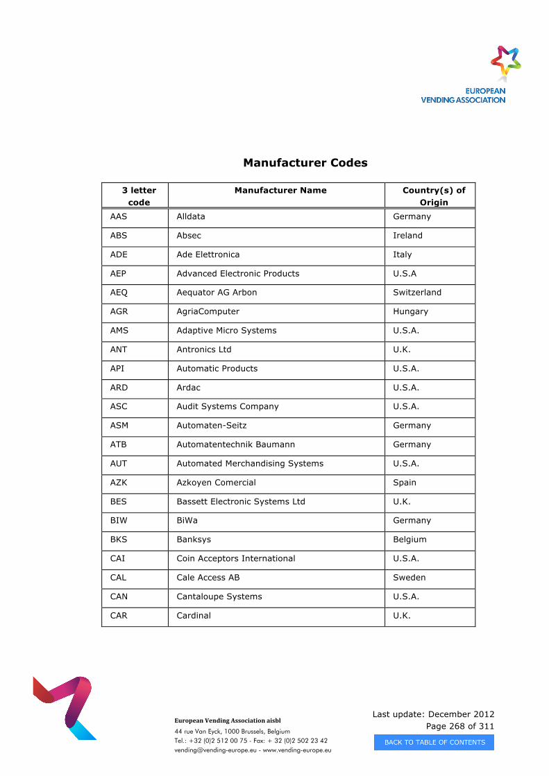
Last update: December 2012 Page 268 of 311
European Vending Association aisbl
44 rue Van Eyck, 1000 Brussels, Belgium Tel.: +32 (0)2 512 00 75 - Fax: + 32 (0)2 502 23 42 [email protected] - www.vending-europe.eu
Manufacturer Codes
3 letter code
Manufacturer Name
Country(s) of Origin
AAS Alldata Germany
ABS Absec Ireland
ADE Ade Elettronica Italy
AEP Advanced Electronic Products U.S.A
AEQ Aequator AG Arbon Switzerland
AGR AgriaComputer Hungary
AMS Adaptive Micro Systems U.S.A.
ANT Antronics Ltd U.K.
API Automatic Products U.S.A.
ARD Ardac U.S.A.
ASC Audit Systems Company U.S.A.
ASM Automaten-Seitz Germany
ATB Automatentechnik Baumann Germany
AUT Automated Merchandising Systems U.S.A.
AZK Azkoyen Comercial Spain
BES Bassett Electronic Systems Ltd U.K.
BIW BiWa Germany
BKS Banksys Belgium
CAI Coin Acceptors International U.S.A.
CAL Cale Access AB Sweden
CAN Cantaloupe Systems U.S.A.
CAR Cardinal U.K.
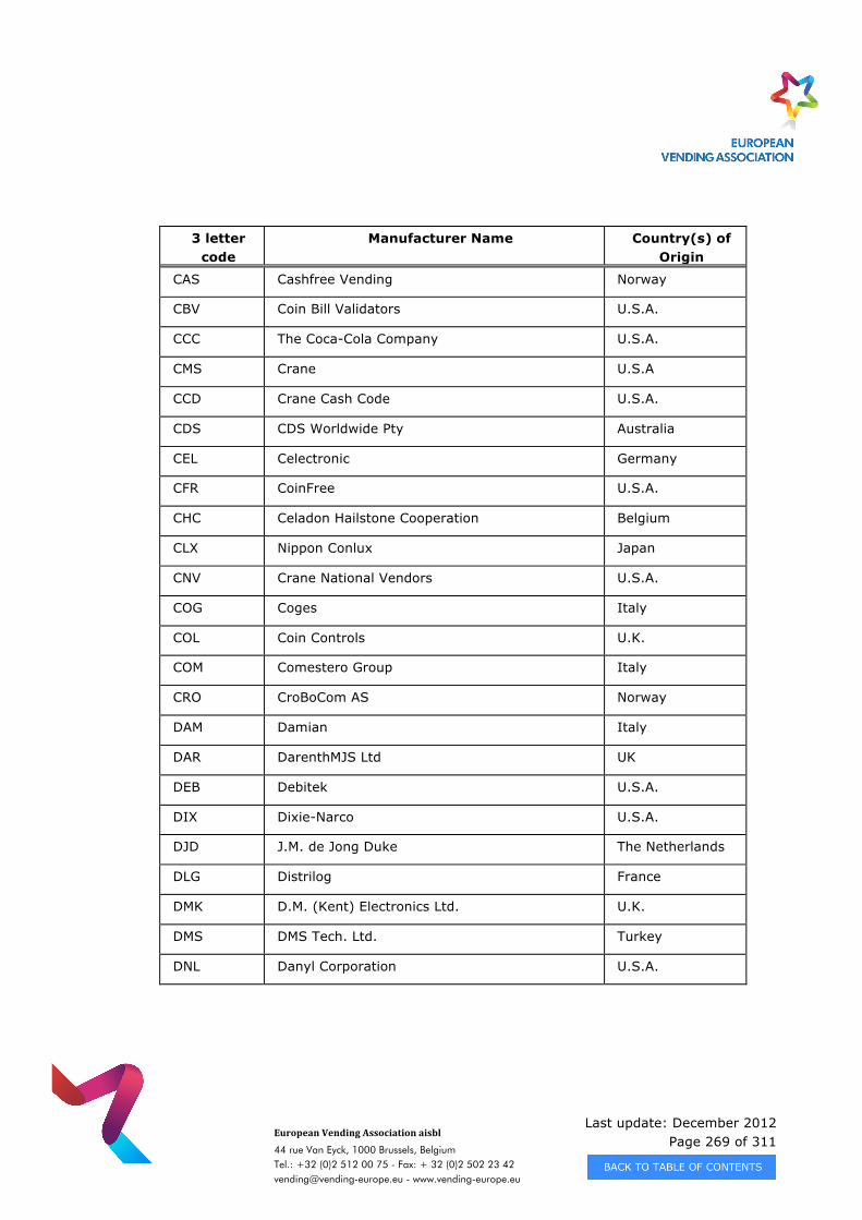
Last update: December 2012 Page 269 of 311
European Vending Association aisbl
44 rue Van Eyck, 1000 Brussels, Belgium Tel.: +32 (0)2 512 00 75 - Fax: + 32 (0)2 502 23 42 [email protected] - www.vending-europe.eu
3 letter code
Manufacturer Name
Country(s) of Origin
CAS Cashfree Vending Norway
CBV Coin Bill Validators U.S.A.
CCC The Coca-Cola Company U.S.A.
CMS Crane U.S.A
CCD Crane Cash Code U.S.A.
CDS CDS Worldwide Pty Australia
CEL Celectronic Germany
CFR CoinFree U.S.A.
CHC Celadon Hailstone Cooperation Belgium
CLX Nippon Conlux Japan
CNV Crane National Vendors U.S.A.
COG Coges Italy
COL Coin Controls U.K.
COM Comestero Group Italy
CRO CroBoCom AS Norway
DAM Damian Italy
DAR DarenthMJS Ltd UK
DEB Debitek U.S.A.
DIX Dixie-Narco U.S.A.
DJD J.M. de Jong Duke The Netherlands
DLG Distrilog France
DMK D.M. (Kent) Electronics Ltd. U.K.
DMS DMS Tech. Ltd. Turkey
DNL Danyl Corporation U.S.A.
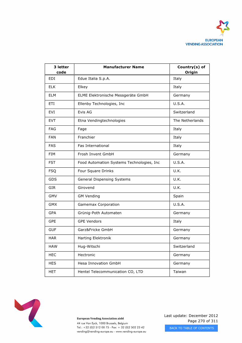
Last update: December 2012 Page 270 of 311
European Vending Association aisbl
44 rue Van Eyck, 1000 Brussels, Belgium Tel.: +32 (0)2 512 00 75 - Fax: + 32 (0)2 502 23 42 [email protected] - www.vending-europe.eu
3 letter code
Manufacturer Name
Country(s) of Origin
EDI Edue Italia S.p.A. Italy
ELK Elkey Italy
ELM ELME Elektronische Messgeräte GmbH Germany
ETI Ellenby Technologies, Inc U.S.A.
EVI Evis AG Switzerland
EVT Etna Vendingtechnologies The Netherlands
FAG Fage Italy
FAN Franchier Italy
FAS Fas International Italy
FIM Frosh Invent GmbH Germany
FST Food Automation Systems Technologies, Inc U.S.A.
FSQ Four Square Drinks U.K.
GDS General Dispensing Systems U.K.
GIR Girovend U.K.
GMV GM Vending Spain
GMX Gamemax Corporation U.S.A.
GPA Grünig-Poth Automaten Germany
GPE GPE Vendors Italy
GUF Garz&Fricke GmbH Germany
HAR Harting Elektronik Germany
HAW Hug-Witschi Switzerland
HEC Hectronic Germany
HES Hesa Innovation GmbH Germany
HET Hentel Telecommunication CO, LTD Taiwan
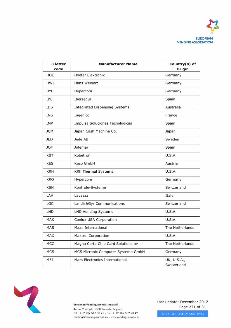
Last update: December 2012 Page 271 of 311
European Vending Association aisbl
44 rue Van Eyck, 1000 Brussels, Belgium Tel.: +32 (0)2 512 00 75 - Fax: + 32 (0)2 502 23 42 [email protected] - www.vending-europe.eu
3 letter code
Manufacturer Name
Country(s) of Origin
HOE Hoefer Elektronik Germany
HWI Hans Weinert Germany
HYC Hypercom Germany
IBE Ibersegur Spain
IDS Integrated Dispensing Systems Australia
ING Ingenico France
IMP Impulsa Soluciones Tecnológicas Spain
JCM Japan Cash Machine Co. Japan
JED Jede AB Sweden
JOF Jofemar Spain
KBT Kobetron U.S.A.
KES Keso GmbH Austria
KRH KRh Thermal Systems U.S.A.
KRO Hypercom Germany
KSN Kontrole-Systeme Switzerland
LAV Lavazza Italy
LGC Landis&Gyr Communications Switzerland
LHD LHD Vending Systems U.S.A.
MAK Conlux USA Corporation U.S.A.
MAS Maas International The Netherlands
MAX Maxtrol Corporation U.S.A.
MCC Magna Carta Chip Card Solutions bv The Netherlands
MCS MCS Micronic Computer Systeme GmbH Germany
MEI Mars Electronics International UK, U.S.A., Switzerland
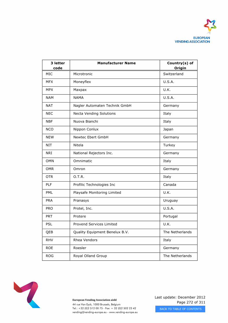
Last update: December 2012 Page 272 of 311
European Vending Association aisbl
44 rue Van Eyck, 1000 Brussels, Belgium Tel.: +32 (0)2 512 00 75 - Fax: + 32 (0)2 502 23 42 [email protected] - www.vending-europe.eu
3 letter code
Manufacturer Name
Country(s) of Origin
MIC Microtronic Switzerland
MFX Moneyflex U.S.A.
MPX Maxpax U.K.
NAM NAMA U.S.A.
NAT Nagler Automaten Technik GmbH Germany
NEC Necta Vending Solutions Italy
NBF Nuova Bianchi Italy
NCO Nippon Conlux Japan
NEW Newtec Ebert GmbH Germany
NIT Nitela Turkey
NRI National Rejectors Inc. Germany
OMN Omnimatic Italy
OMR Omron Germany
OTR O.T.R. Italy
PLF Profilic Technologies Inc Canada
PML Playsafe Monitoring Limited U.K.
PRA Pranasys Uruguay
PRO Protel, Inc. U.S.A.
PRT Protere Portugal
PSL Provend Services Limited U.K.
QEB Quality Equipment Benelux B.V. The Netherlands
RHV Rhea Vendors Italy
ROE Roesler Germany
ROG Royal Olland Group The Netherlands
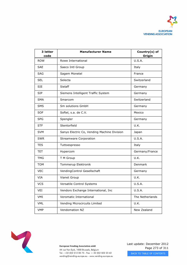
Last update: December 2012 Page 273 of 311
European Vending Association aisbl
44 rue Van Eyck, 1000 Brussels, Belgium Tel.: +32 (0)2 512 00 75 - Fax: + 32 (0)2 502 23 42 [email protected] - www.vending-europe.eu
3 letter code
Manufacturer Name
Country(s) of Origin
ROW Rowe International U.S.A.
SAE Saeco Intl Group Italy
SAG Sagem Monetel France
SEL Selecta Switzerland
SIE Sielaff Germany
SIP Siemens Intelligent Traffic System Germany
SMA Smarcom Switzerland
SMS Sm solutions GmbH Germany
SOF Softel, s.a. de C.V. Mexico
SPG Spengler Germany
STF Stentorfield U.K.
SVM Sanyo Electric Co, Vending Machine Division Japan
SWR Streamware Corporation U.S.A.
TES Tuttoespresso Italy
TET Hypercom Germany/France
TMG T M Group U.K.
TOM Tommerup Elektronik Denmark
VEC VendingControl Gesellschaft Germany
VIA Vianet Group U.K.
VCS Versatile Control Systems U.S.A.
VEI Vendors Exchange International, Inc U.S.A.
VMI Veromatic International The Netherlands
VML Vending Microcircuits Limited U.K.
VMP Vendomation NZ New Zealand
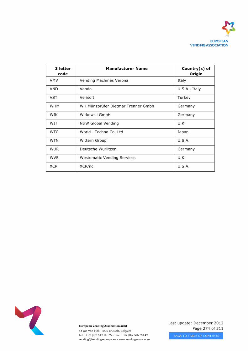
Last update: December 2012 Page 274 of 311
European Vending Association aisbl
44 rue Van Eyck, 1000 Brussels, Belgium Tel.: +32 (0)2 512 00 75 - Fax: + 32 (0)2 502 23 42 [email protected] - www.vending-europe.eu
3 letter code
Manufacturer Name
Country(s) of Origin
VMV Vending Machines Verona Italy
VND Vendo U.S.A., Italy
VST Verisoft Turkey
WHM WH Münzprüfer Dietmar Trenner Gmbh Germany
WIK Witkowsli GmbH Germany
WIT N&W Global Vending U.K.
WTC World . Techno Co, Ltd Japan
WTN Wittern Group U.S.A.
WUR Deutsche Wurlitzer Germany
WVS Westomatic Vending Services U.K.
XCP XCP/nc U.S.A.
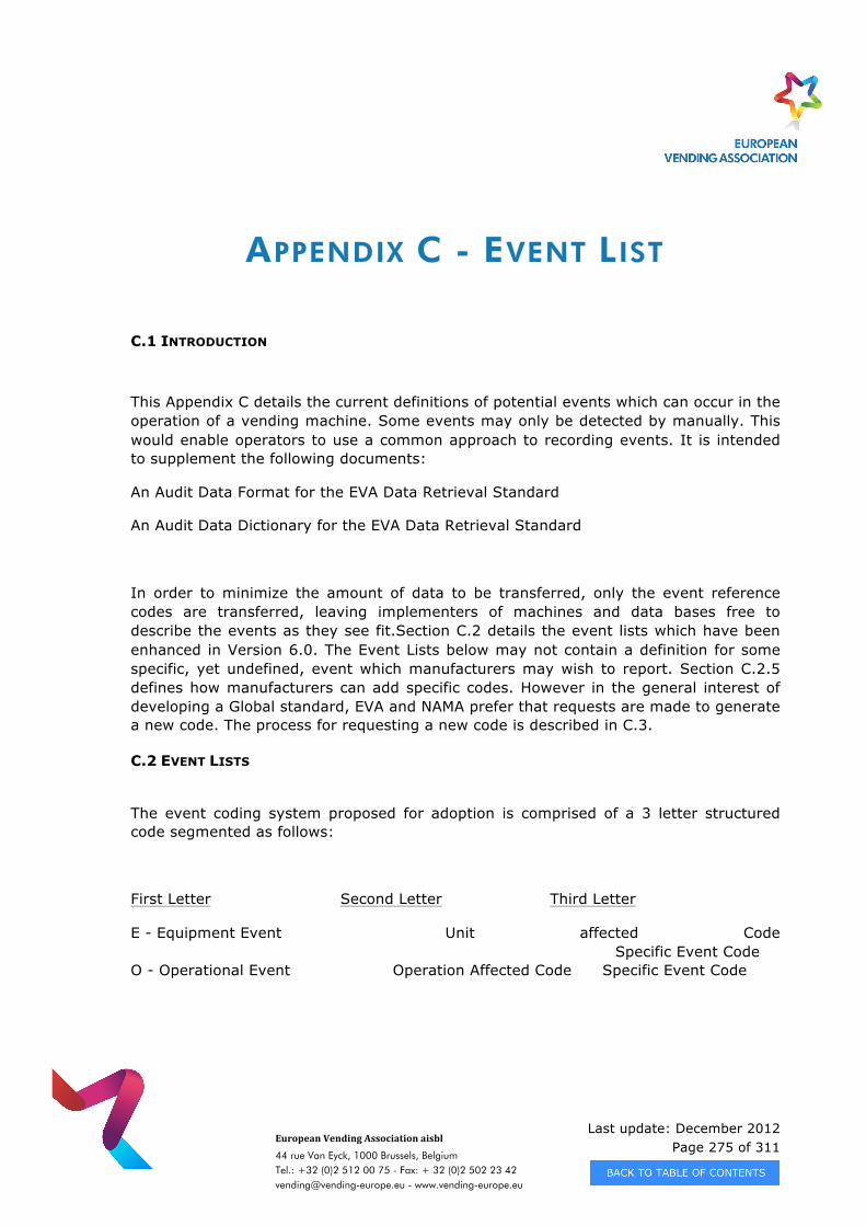
Last update: December 2012 Page 275 of 311
European Vending Association aisbl
44 rue Van Eyck, 1000 Brussels, Belgium Tel.: +32 (0)2 512 00 75 - Fax: + 32 (0)2 502 23 42 [email protected] - www.vending-europe.eu
APPENDIX C - EVENT LIST
C.1 INTRODUCTION
This Appendix C details the current definitions of potential events which can occur in the operation of a vending machine. Some events may only be detected by manually. This would enable operators to use a common approach to recording events. It is intended to supplement the following documents:
An Audit Data Format for the EVA Data Retrieval Standard
An Audit Data Dictionary for the EVA Data Retrieval Standard
In order to minimize the amount of data to be transferred, only the event reference codes are transferred, leaving implementers of machines and data bases free to describe the events as they see fit.Section C.2 details the event lists which have been enhanced in Version 6.0. The Event Lists below may not contain a definition for some specific, yet undefined, event which manufacturers may wish to report. Section C.2.5 defines how manufacturers can add specific codes. However in the general interest of developing a Global standard, EVA and NAMA prefer that requests are made to generate a new code. The process for requesting a new code is described in C.3.
C.2 EVENT LISTS
The event coding system proposed for adoption is comprised of a 3 letter structured code segmented as follows:
First Letter Second Letter Third Letter
E - Equipment Event Unit affected Code Specific Event Code O - Operational Event Operation Affected Code Specific Event Code
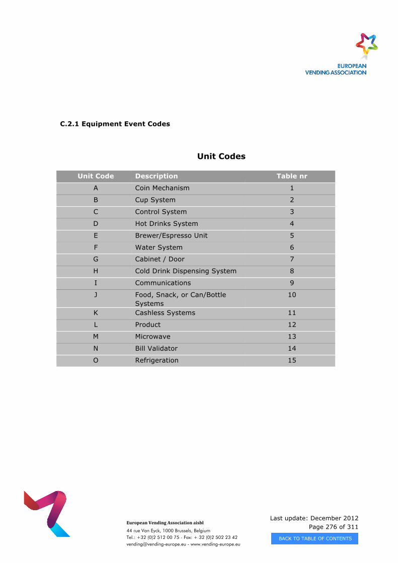
Last update: December 2012 Page 276 of 311
European Vending Association aisbl
44 rue Van Eyck, 1000 Brussels, Belgium Tel.: +32 (0)2 512 00 75 - Fax: + 32 (0)2 502 23 42 [email protected] - www.vending-europe.eu
C.2.1 Equipment Event Codes
Unit Codes
Unit Code Description Table nr
A Coin Mechanism 1
B Cup System 2
C Control System 3
D Hot Drinks System 4
E Brewer/Espresso Unit 5
F Water System 6
G Cabinet / Door 7
H Cold Drink Dispensing System 8
I Communications 9
J Food, Snack, or Can/Bottle Systems
10
K Cashless Systems 11
L Product 12
M Microwave 13
N Bill Validator 14
O Refrigeration 15
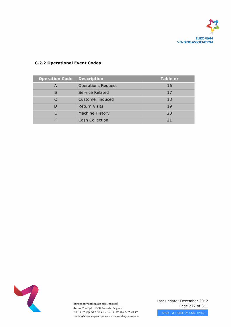
Last update: December 2012 Page 277 of 311
European Vending Association aisbl
44 rue Van Eyck, 1000 Brussels, Belgium Tel.: +32 (0)2 512 00 75 - Fax: + 32 (0)2 502 23 42 [email protected] - www.vending-europe.eu
C.2.2 Operational Event Codes
Operation Code Description Table nr
A Operations Request 16
B Service Related 17
C Customer induced 18
D Return Visits 19
E Machine History 20
F Cash Collection 21
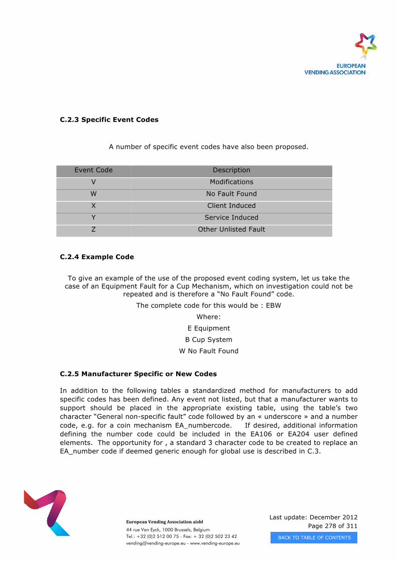
Last update: December 2012 Page 278 of 311
European Vending Association aisbl
44 rue Van Eyck, 1000 Brussels, Belgium Tel.: +32 (0)2 512 00 75 - Fax: + 32 (0)2 502 23 42 [email protected] - www.vending-europe.eu
C.2.3 Specific Event Codes
A number of specific event codes have also been proposed.
Event Code Description
V Modifications
W No Fault Found
X Client Induced
Y Service Induced
Z Other Unlisted Fault
C.2.4 Example Code
To give an example of the use of the proposed event coding system, let us take the case of an Equipment Fault for a Cup Mechanism, which on investigation could not be
repeated and is therefore a “No Fault Found” code.
The complete code for this would be : EBW
Where:
E Equipment
B Cup System
W No Fault Found
C.2.5 Manufacturer Specific or New Codes
In addition to the following tables a standardized method for manufacturers to add specific codes has been defined. Any event not listed, but that a manufacturer wants to support should be placed in the appropriate existing table, using the table’s two character “General non-specific fault” code followed by an « underscore » and a number code, e.g. for a coin mechanism EA_numbercode. If desired, additional information defining the number code could be included in the EA106 or EA204 user defined elements. The opportunity for , a standard 3 character code to be created to replace an EA_number code if deemed generic enough for global use is described in C.3.
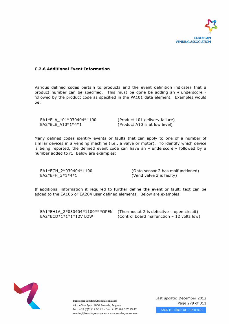
Last update: December 2012 Page 279 of 311
European Vending Association aisbl
44 rue Van Eyck, 1000 Brussels, Belgium Tel.: +32 (0)2 512 00 75 - Fax: + 32 (0)2 502 23 42 [email protected] - www.vending-europe.eu
C.2.6 Additional Event Information
Various defined codes pertain to products and the event definition indicates that a product number can be specified. This must be done be adding an « underscore » followed by the product code as specified in the PA101 data element. Examples would be:
EA1*ELA_101*030404*1100 (Product 101 delivery failure) EA2*ELE_A10*1*4*1 (Product A10 is at low level)
Many defined codes identify events or faults that can apply to one of a number of similar devices in a vending machine (i.e., a valve or motor). To identify which device is being reported, the defined event code can have an « underscore » followed by a number added to it. Below are examples:
EA1*ECH_2*030404*1100 (Opto sensor 2 has malfunctioned) EA2*EFH_3*1*4*1 (Vend valve 3 is faulty)
If additional information it required to further define the event or fault, text can be added to the EA106 or EA204 user defined elements. Below are examples:
EA1*EH1A_2*030404*1100***OPEN (Thermostat 2 is defective – open circuit) EA2*ECD*1*1*1*12V LOW (Control board malfunction – 12 volts low)
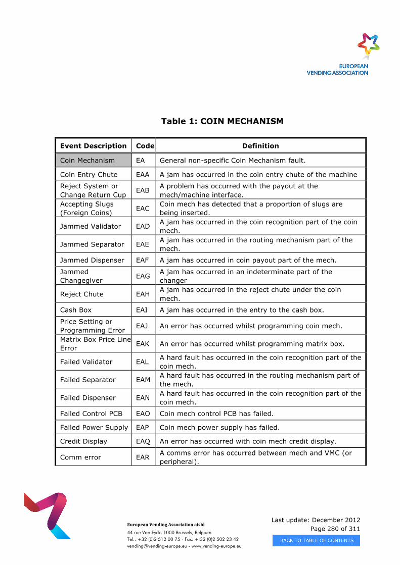
Last update: December 2012 Page 280 of 311
European Vending Association aisbl
44 rue Van Eyck, 1000 Brussels, Belgium Tel.: +32 (0)2 512 00 75 - Fax: + 32 (0)2 502 23 42 [email protected] - www.vending-europe.eu
Table 1: COIN MECHANISM
Event Description Code Definition
Coin Mechanism EA General non-specific Coin Mechanism fault.
Coin Entry Chute EAA A jam has occurred in the coin entry chute of the machine
Reject System or Change Return Cup
EAB A problem has occurred with the payout at the mech/machine interface.
Accepting Slugs (Foreign Coins) EAC Coin mech has detected that a proportion of slugs are
being inserted.
Jammed Validator EAD A jam has occurred in the coin recognition part of the coin mech.
Jammed Separator EAE A jam has occurred in the routing mechanism part of the mech.
Jammed Dispenser EAF A jam has occurred in coin payout part of the mech.
Jammed Changegiver EAG A jam has occurred in an indeterminate part of the
changer
Reject Chute EAH A jam has occurred in the reject chute under the coin mech.
Cash Box EAI A jam has occurred in the entry to the cash box.
Price Setting or Programming Error EAJ An error has occurred whilst programming coin mech.
Matrix Box Price Line Error EAK An error has occurred whilst programming matrix box.
Failed Validator EAL A hard fault has occurred in the coin recognition part of the coin mech.
Failed Separator EAM A hard fault has occurred in the routing mechanism part of the mech.
Failed Dispenser EAN A hard fault has occurred in the coin recognition part of the coin mech.
Failed Control PCB EAO Coin mech control PCB has failed.
Failed Power Supply EAP Coin mech power supply has failed.
Credit Display EAQ An error has occurred with coin mech credit display.
Comm error EAR A comms error has occurred between mech and VMC (or peripheral).
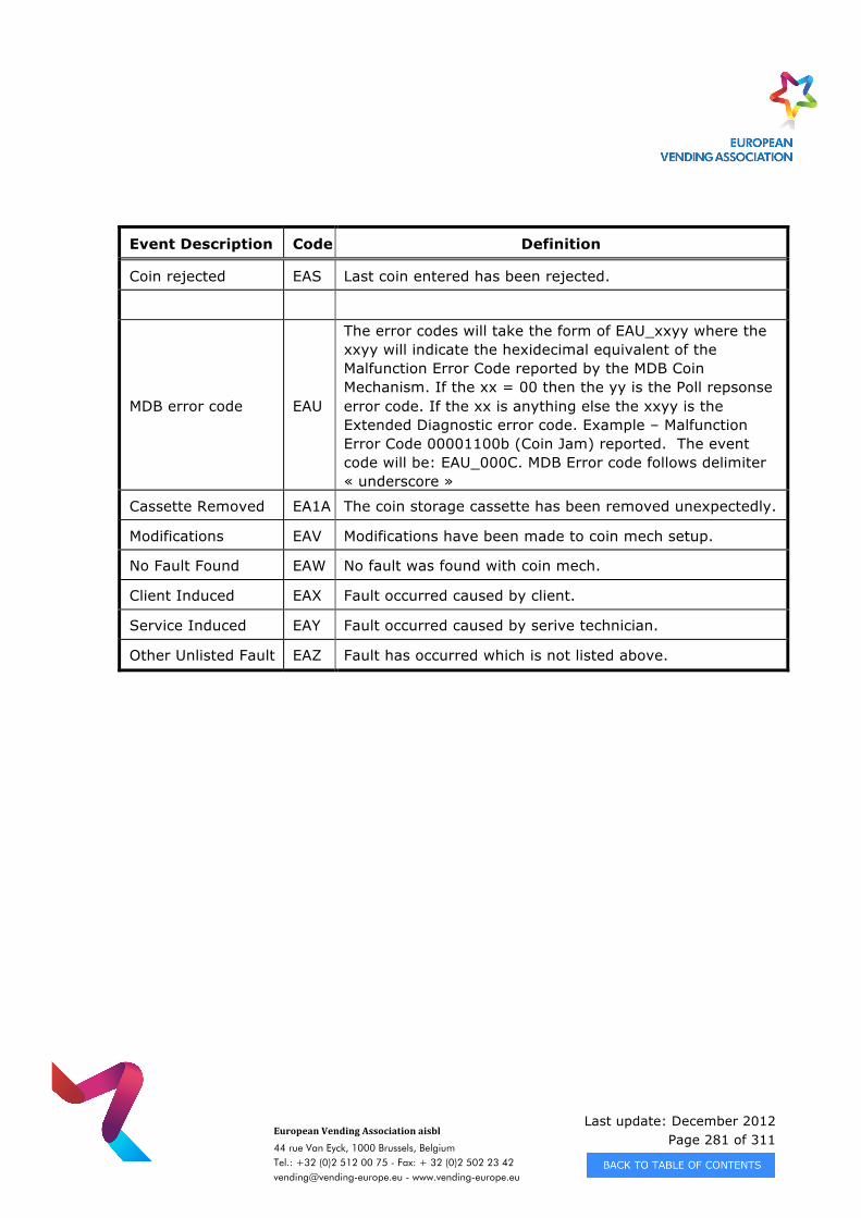
Last update: December 2012 Page 281 of 311
European Vending Association aisbl
44 rue Van Eyck, 1000 Brussels, Belgium Tel.: +32 (0)2 512 00 75 - Fax: + 32 (0)2 502 23 42 [email protected] - www.vending-europe.eu
Event Description Code Definition
Coin rejected EAS Last coin entered has been rejected.
MDB error code EAU
The error codes will take the form of EAU_xxyy where the xxyy will indicate the hexidecimal equivalent of the Malfunction Error Code reported by the MDB Coin Mechanism. If the xx = 00 then the yy is the Poll repsonse error code. If the xx is anything else the xxyy is the Extended Diagnostic error code. Example – Malfunction Error Code 00001100b (Coin Jam) reported. The event code will be: EAU_000C. MDB Error code follows delimiter « underscore »
Cassette Removed EA1A The coin storage cassette has been removed unexpectedly.
Modifications EAV Modifications have been made to coin mech setup.
No Fault Found EAW No fault was found with coin mech.
Client Induced EAX Fault occurred caused by client.
Service Induced EAY Fault occurred caused by serive technician.
Other Unlisted Fault EAZ Fault has occurred which is not listed above.
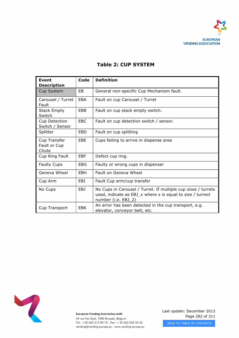
Last update: December 2012 Page 282 of 311
European Vending Association aisbl
44 rue Van Eyck, 1000 Brussels, Belgium Tel.: +32 (0)2 512 00 75 - Fax: + 32 (0)2 502 23 42 [email protected] - www.vending-europe.eu
Table 2: CUP SYSTEM
Event Description
Code Definition
Cup System EB General non-specific Cup Mechanism fault.
Carousel / Turret Fault
EBA Fault on cup Carousel / Turret
Stack Empty Switch
EBB Fault on cup stack empty switch.
Cup Detection Switch / Sensor
EBC Fault on cup detection switch / sensor.
Splitter EBD Fault on cup splitting
Cup Transfer Fault or Cup Chute
EBE Cups failing to arrive in dispense area
Cup Ring Fault EBF Defect cup ring.
Faulty Cups EBG Faulty or wrong cups in dispenser
Geneva Wheel EBH Fault on Geneva Wheel
Cup Arm EBI Fault Cup arm/cup transfer
No Cups EBJ No Cups in Carousel / Turret. If multiple cup sizes / turrets used, indicate as EBJ_x where x is equal to size / turrect number (i.e. EBJ_2)
Cup Transport EBK An error has been detected in the cup transport, e.g. elevator, conveyor belt, etc.
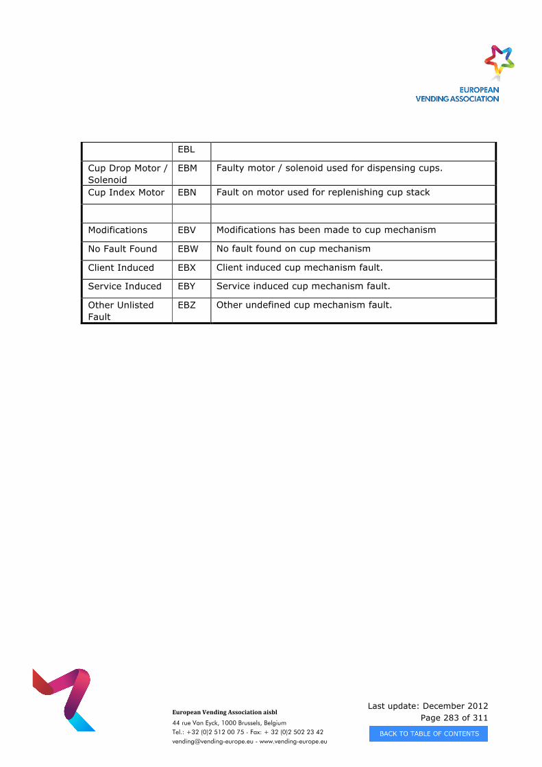
Last update: December 2012 Page 283 of 311
European Vending Association aisbl
44 rue Van Eyck, 1000 Brussels, Belgium Tel.: +32 (0)2 512 00 75 - Fax: + 32 (0)2 502 23 42 [email protected] - www.vending-europe.eu
EBL
Cup Drop Motor / Solenoid
EBM Faulty motor / solenoid used for dispensing cups.
Cup Index Motor EBN Fault on motor used for replenishing cup stack
Modifications EBV Modifications has been made to cup mechanism
No Fault Found EBW No fault found on cup mechanism
Client Induced EBX Client induced cup mechanism fault.
Service Induced EBY Service induced cup mechanism fault.
Other Unlisted Fault
EBZ Other undefined cup mechanism fault.
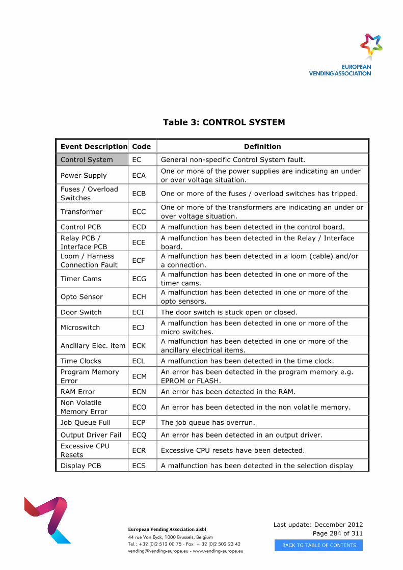
Last update: December 2012 Page 284 of 311
European Vending Association aisbl
44 rue Van Eyck, 1000 Brussels, Belgium Tel.: +32 (0)2 512 00 75 - Fax: + 32 (0)2 502 23 42 [email protected] - www.vending-europe.eu
Table 3: CONTROL SYSTEM
Event Description Code Definition
Control System EC General non-specific Control System fault.
Power Supply ECA One or more of the power supplies are indicating an under or over voltage situation.
Fuses / Overload Switches ECB One or more of the fuses / overload switches has tripped.
Transformer ECC One or more of the transformers are indicating an under or over voltage situation.
Control PCB ECD A malfunction has been detected in the control board. Relay PCB / Interface PCB ECE A malfunction has been detected in the Relay / Interface
board. Loom / Harness Connection Fault ECF A malfunction has been detected in a loom (cable) and/or
a connection.
Timer Cams ECG A malfunction has been detected in one or more of the timer cams.
Opto Sensor ECH A malfunction has been detected in one or more of the opto sensors.
Door Switch ECI The door switch is stuck open or closed.
Microswitch ECJ A malfunction has been detected in one or more of the micro switches.
Ancillary Elec. item ECK A malfunction has been detected in one or more of the ancillary electrical items.
Time Clocks ECL A malfunction has been detected in the time clock. Program Memory Error ECM
An error has been detected in the program memory e.g. EPROM or FLASH.
RAM Error ECN An error has been detected in the RAM. Non Volatile Memory Error ECO An error has been detected in the non volatile memory.
Job Queue Full ECP The job queue has overrun.
Output Driver Fail ECQ An error has been detected in an output driver. Excessive CPU Resets ECR Excessive CPU resets have been detected.
Display PCB ECS A malfunction has been detected in the selection display
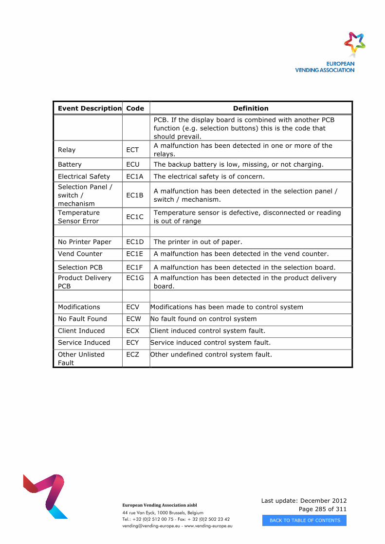
Last update: December 2012 Page 285 of 311
European Vending Association aisbl
44 rue Van Eyck, 1000 Brussels, Belgium Tel.: +32 (0)2 512 00 75 - Fax: + 32 (0)2 502 23 42 [email protected] - www.vending-europe.eu
Event Description Code Definition
PCB. If the display board is combined with another PCB function (e.g. selection buttons) this is the code that should prevail.
Relay ECT A malfunction has been detected in one or more of the relays.
Battery ECU The backup battery is low, missing, or not charging.
Electrical Safety EC1A The electrical safety is of concern. Selection Panel / switch / mechanism
EC1B A malfunction has been detected in the selection panel / switch / mechanism.
Temperature Sensor Error EC1C Temperature sensor is defective, disconnected or reading
is out of range No Printer Paper EC1D The printer in out of paper.
Vend Counter EC1E A malfunction has been detected in the vend counter.
Selection PCB EC1F A malfunction has been detected in the selection board. Product Delivery PCB
EC1G A malfunction has been detected in the product delivery board.
Modifications ECV Modifications has been made to control system
No Fault Found ECW No fault found on control system
Client Induced ECX Client induced control system fault.
Service Induced ECY Service induced control system fault.
Other Unlisted Fault
ECZ Other undefined control system fault.
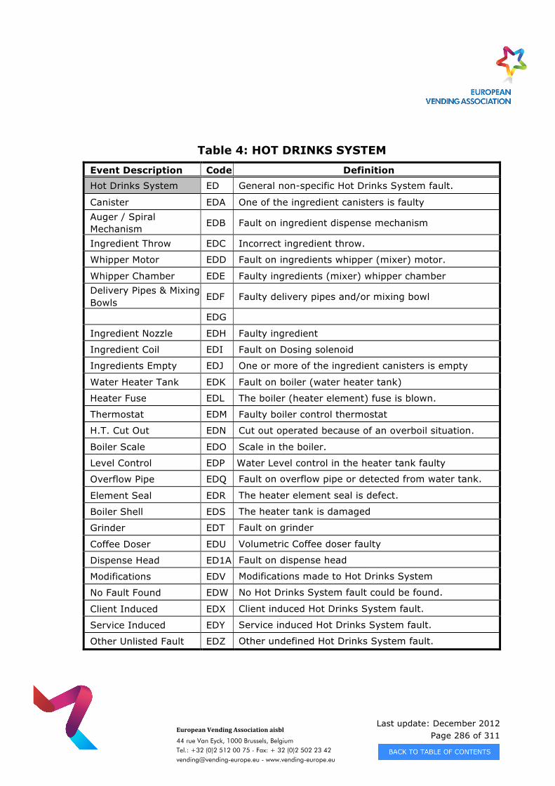
Last update: December 2012 Page 286 of 311
European Vending Association aisbl
44 rue Van Eyck, 1000 Brussels, Belgium Tel.: +32 (0)2 512 00 75 - Fax: + 32 (0)2 502 23 42 [email protected] - www.vending-europe.eu
Table 4: HOT DRINKS SYSTEM
Event Description Code Definition Hot Drinks System ED General non-specific Hot Drinks System fault.
Canister EDA One of the ingredient canisters is faulty Auger / Spiral Mechanism EDB Fault on ingredient dispense mechanism
Ingredient Throw EDC Incorrect ingredient throw.
Whipper Motor EDD Fault on ingredients whipper (mixer) motor.
Whipper Chamber EDE Faulty ingredients (mixer) whipper chamber Delivery Pipes & Mixing Bowls EDF Faulty delivery pipes and/or mixing bowl
EDG
Ingredient Nozzle EDH Faulty ingredient
Ingredient Coil EDI Fault on Dosing solenoid
Ingredients Empty EDJ One or more of the ingredient canisters is empty
Water Heater Tank EDK Fault on boiler (water heater tank)
Heater Fuse EDL The boiler (heater element) fuse is blown.
Thermostat EDM Faulty boiler control thermostat
H.T. Cut Out EDN Cut out operated because of an overboil situation.
Boiler Scale EDO Scale in the boiler.
Level Control EDP Water Level control in the heater tank faulty
Overflow Pipe EDQ Fault on overflow pipe or detected from water tank.
Element Seal EDR The heater element seal is defect.
Boiler Shell EDS The heater tank is damaged
Grinder EDT Fault on grinder
Coffee Doser EDU Volumetric Coffee doser faulty
Dispense Head ED1A Fault on dispense head
Modifications EDV Modifications made to Hot Drinks System
No Fault Found EDW No Hot Drinks System fault could be found.
Client Induced EDX Client induced Hot Drinks System fault.
Service Induced EDY Service induced Hot Drinks System fault.
Other Unlisted Fault EDZ Other undefined Hot Drinks System fault.
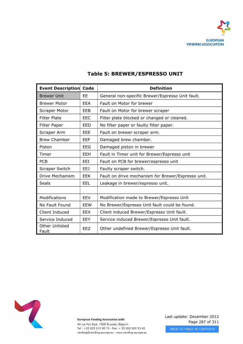
Last update: December 2012 Page 287 of 311
European Vending Association aisbl
44 rue Van Eyck, 1000 Brussels, Belgium Tel.: +32 (0)2 512 00 75 - Fax: + 32 (0)2 502 23 42 [email protected] - www.vending-europe.eu
Table 5: BREWER/ESPRESSO UNIT
Event Description Code Definition
Brewer Unit EE General non-specific Brewer/Espresso Unit fault.
Brewer Motor EEA Fault on Motor for brewer
Scraper Motor EEB Fault on Motor for brewer scraper
Filter Plate EEC Filter plate blocked or changed or cleaned.
Filter Paper EED No filter paper or faulty filter paper.
Scraper Arm EEE Fault on brewer scraper arm.
Brew Chamber EEF Damaged brew chamber.
Piston EEG Damaged piston in brewer
Timer EEH Fault in Timer unit for Brewer/Espresso unit
PCB EEI Fault on PCB for brewer/espresso unit
Scraper Switch EEJ Faulty scraper switch.
Drive Mechanism EEK Fault on drive mechanism for Brewer/Espresso unit.
Seals EEL Leakage in brewer/espresso unit.
Modifications EEV Modification made to Brewer/Espresso Unit
No Fault Found EEW No Brewer/Espresso Unit fault could be found.
Client Induced EEX Client induced Brewer/Espresso Unit fault.
Service Induced EEY Service induced Brewer/Espresso Unit fault. Other Unlisted Fault EEZ Other undefined Brewer/Espresso Unit fault.
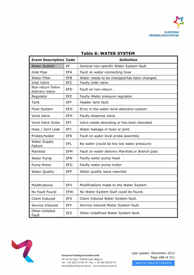
Last update: December 2012 Page 288 of 311
European Vending Association aisbl
44 rue Van Eyck, 1000 Brussels, Belgium Tel.: +32 (0)2 512 00 75 - Fax: + 32 (0)2 502 23 42 [email protected] - www.vending-europe.eu
Table 6: WATER SYSTEM Event Description Code Definition
Water System EF General non-specific Water System fault.
Inlet Pipe EFA Fault on water connecting hose
Water Filter EFB Water needs to be changed/has been changed. Inlet Valve EFC Faulty Inlet valve Non-return Valve Delivery Valve EFD Fault on non-return .
Regulator EFE Faulty Water pressure regulator
Tank EFF Header tank fault
Float System EFG Error in the water level detection system.
Vend Valve EFH Faulty dispense valve
Vend Valve Scale EFI Valve needs descaling or has been descaled
Hose / Joint Leak EFJ Water leakage in hose or joint.
Probes/holder EFK Fault on water level probe assembly
Water Supply Failure EFL No water (could be too low water pressure)
Manifold EFM Fault on water delivery Manifold or Branch pipe
Water Pump EFN Faulty water pump head
Pump Motor EFO Faulty water pump motor
Water Quality EFP Water quality issue reported
Modifications EFV Modifications made to the Water System
No Fault Found EFW No Water System fault could be found.
Client Induced EFX Client induced Water System fault.
Service Induced EFY Service induced Water System fault.
Other Unlisted Fault EFZ Other undefined Water System fault.
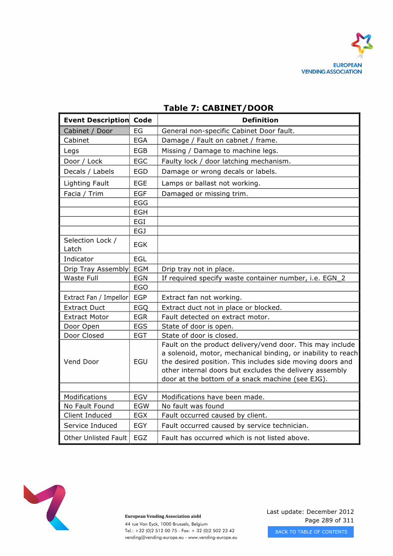
Last update: December 2012 Page 289 of 311
European Vending Association aisbl
44 rue Van Eyck, 1000 Brussels, Belgium Tel.: +32 (0)2 512 00 75 - Fax: + 32 (0)2 502 23 42 [email protected] - www.vending-europe.eu
Table 7: CABINET/DOOR Event Description Code Definition Cabinet / Door EG General non-specific Cabinet Door fault. Cabinet EGA Damage / Fault on cabnet / frame. Legs EGB Missing / Damage to machine legs. Door / Lock EGC Faulty lock / door latching mechanism. Decals / Labels EGD Damage or wrong decals or labels.
Lighting Fault EGE Lamps or ballast not working. Facia / Trim EGF Damaged or missing trim. EGG EGH EGI EGJ Selection Lock / Latch EGK
Indicator EGL Drip Tray Assembly EGM Drip tray not in place. Waste Full EGN If required specify waste container number, i.e. EGN_2 EGO Extract Fan / Impellor EGP Extract fan not working. Extract Duct EGQ Extract duct not in place or blocked. Extract Motor EGR Fault detected on extract motor. Door Open EGS State of door is open. Door Closed EGT State of door is closed.
Vend Door EGU
Fault on the product delivery/vend door. This may include a solenoid, motor, mechanical binding, or inability to reach the desired position. This includes side moving doors and other internal doors but excludes the delivery assembly door at the bottom of a snack machine (see EJG).
Modifications EGV Modifications have been made. No Fault Found EGW No fault was found Client Induced EGX Fault occurred caused by client. Service Induced EGY Fault occurred caused by service technician.
Other Unlisted Fault EGZ Fault has occurred which is not listed above.
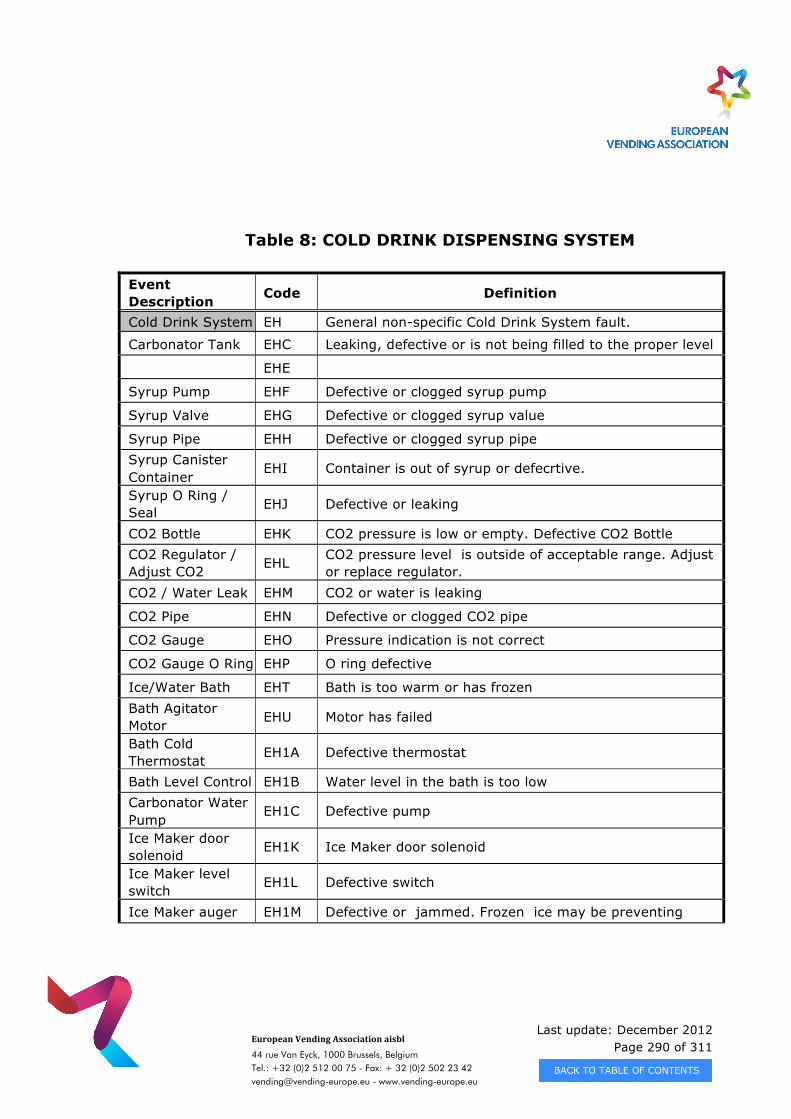
Last update: December 2012 Page 290 of 311
European Vending Association aisbl
44 rue Van Eyck, 1000 Brussels, Belgium Tel.: +32 (0)2 512 00 75 - Fax: + 32 (0)2 502 23 42 [email protected] - www.vending-europe.eu
Table 8: COLD DRINK DISPENSING SYSTEM
Event Description Code Definition
Cold Drink System EH General non-specific Cold Drink System fault.
Carbonator Tank EHC Leaking, defective or is not being filled to the proper level
EHE
Syrup Pump EHF Defective or clogged syrup pump
Syrup Valve EHG Defective or clogged syrup value
Syrup Pipe EHH Defective or clogged syrup pipe Syrup Canister Container
EHI Container is out of syrup or defecrtive.
Syrup O Ring / Seal EHJ Defective or leaking
CO2 Bottle EHK CO2 pressure is low or empty. Defective CO2 Bottle CO2 Regulator / Adjust CO2 EHL CO2 pressure level is outside of acceptable range. Adjust
or replace regulator. CO2 / Water Leak EHM CO2 or water is leaking
CO2 Pipe EHN Defective or clogged CO2 pipe
CO2 Gauge EHO Pressure indication is not correct
CO2 Gauge O Ring EHP O ring defective
Ice/Water Bath EHT Bath is too warm or has frozen Bath Agitator Motor EHU Motor has failed
Bath Cold Thermostat EH1A Defective thermostat
Bath Level Control EH1B Water level in the bath is too low Carbonator Water Pump
EH1C Defective pump
Ice Maker door solenoid EH1K Ice Maker door solenoid
Ice Maker level switch EH1L Defective switch
Ice Maker auger EH1M Defective or jammed. Frozen ice may be preventing
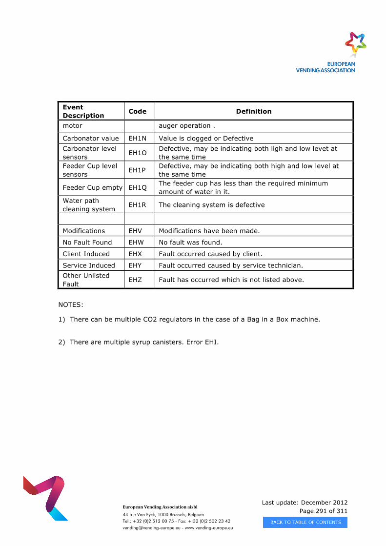
Last update: December 2012 Page 291 of 311
European Vending Association aisbl
44 rue Van Eyck, 1000 Brussels, Belgium Tel.: +32 (0)2 512 00 75 - Fax: + 32 (0)2 502 23 42 [email protected] - www.vending-europe.eu
Event Description Code Definition
motor auger operation .
Carbonator value EH1N Value is clogged or Defective Carbonator level sensors EH1O Defective, may be indicating both ligh and low levet at
the same time Feeder Cup level sensors EH1P Defective, may be indicating both high and low level at
the same time
Feeder Cup empty EH1Q The feeder cup has less than the required minimum amount of water in it.
Water path cleaning system EH1R The cleaning system is defective
Modifications EHV Modifications have been made.
No Fault Found EHW No fault was found.
Client Induced EHX Fault occurred caused by client.
Service Induced EHY Fault occurred caused by service technician. Other Unlisted Fault
EHZ Fault has occurred which is not listed above.
NOTES:
1) There can be multiple CO2 regulators in the case of a Bag in a Box machine.
2) There are multiple syrup canisters. Error EHI.
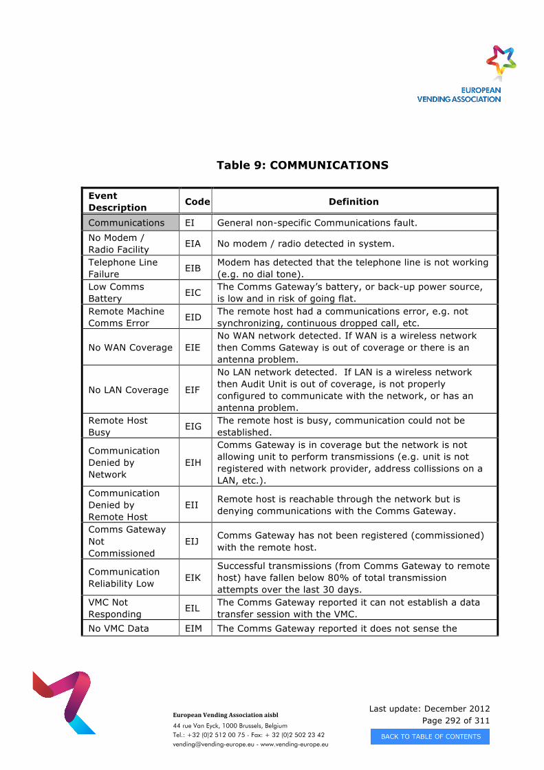
Last update: December 2012 Page 292 of 311
European Vending Association aisbl
44 rue Van Eyck, 1000 Brussels, Belgium Tel.: +32 (0)2 512 00 75 - Fax: + 32 (0)2 502 23 42 [email protected] - www.vending-europe.eu
Table 9: COMMUNICATIONS
Event Description Code Definition
Communications EI General non-specific Communications fault. No Modem / Radio Facility EIA No modem / radio detected in system.
Telephone Line Failure EIB Modem has detected that the telephone line is not working
(e.g. no dial tone). Low Comms Battery EIC The Comms Gateway’s battery, or back-up power source,
is low and in risk of going flat. Remote Machine Comms Error EID The remote host had a communications error, e.g. not
synchronizing, continuous dropped call, etc.
No WAN Coverage EIE No WAN network detected. If WAN is a wireless network then Comms Gateway is out of coverage or there is an antenna problem.
No LAN Coverage EIF
No LAN network detected. If LAN is a wireless network then Audit Unit is out of coverage, is not properly configured to communicate with the network, or has an antenna problem.
Remote Host Busy EIG The remote host is busy, communication could not be
established.
Communication Denied by Network
EIH
Comms Gateway is in coverage but the network is not allowing unit to perform transmissions (e.g. unit is not registered with network provider, address collissions on a LAN, etc.).
Communication Denied by Remote Host
EII Remote host is reachable through the network but is denying communications with the Comms Gateway.
Comms Gateway Not Commissioned
EIJ Comms Gateway has not been registered (commissioned) with the remote host.
Communication Reliability Low EIK
Successful transmissions (from Comms Gateway to remote host) have fallen below 80% of total transmission attempts over the last 30 days.
VMC Not Responding EIL The Comms Gateway reported it can not establish a data
transfer session with the VMC. No VMC Data EIM The Comms Gateway reported it does not sense the
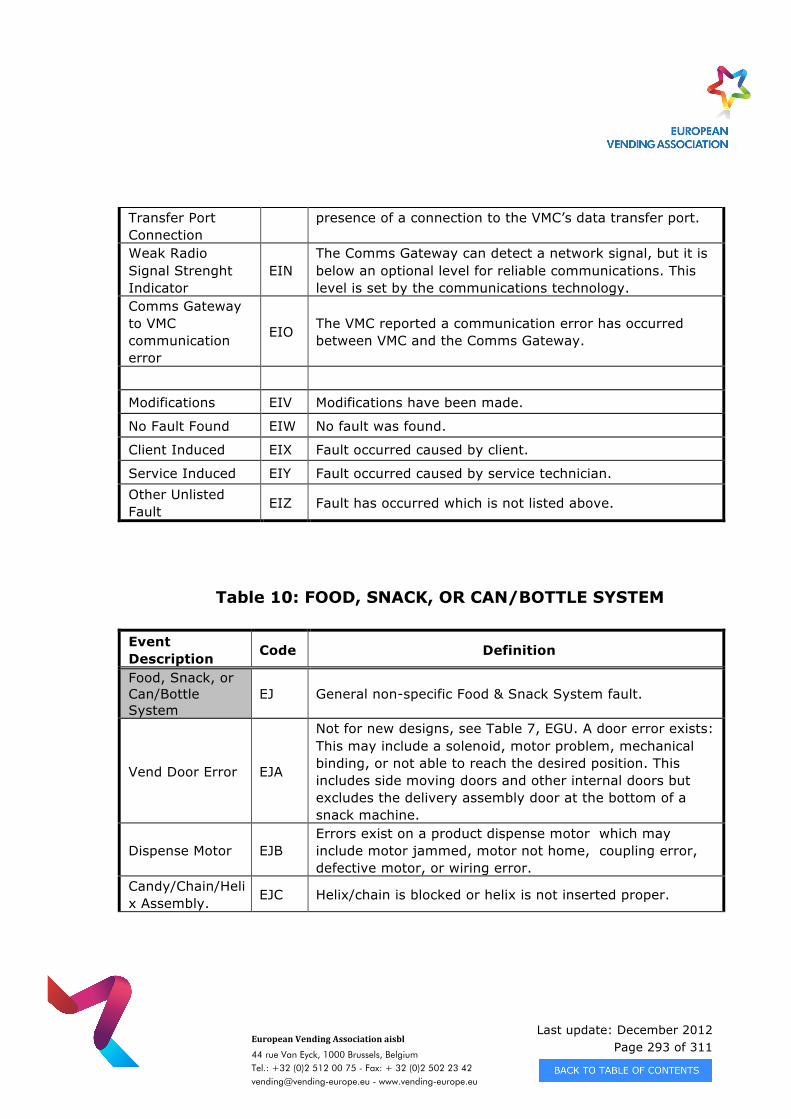
Last update: December 2012 Page 293 of 311
European Vending Association aisbl
44 rue Van Eyck, 1000 Brussels, Belgium Tel.: +32 (0)2 512 00 75 - Fax: + 32 (0)2 502 23 42 [email protected] - www.vending-europe.eu
Transfer Port Connection
presence of a connection to the VMC’s data transfer port.
Weak Radio Signal Strenght Indicator
EIN The Comms Gateway can detect a network signal, but it is below an optional level for reliable communications. This level is set by the communications technology.
Comms Gateway to VMC communication error
EIO The VMC reported a communication error has occurred between VMC and the Comms Gateway.
Modifications EIV Modifications have been made.
No Fault Found EIW No fault was found.
Client Induced EIX Fault occurred caused by client.
Service Induced EIY Fault occurred caused by service technician. Other Unlisted Fault EIZ Fault has occurred which is not listed above.
Table 10: FOOD, SNACK, OR CAN/BOTTLE SYSTEM
Event Description Code Definition
Food, Snack, or Can/Bottle System
EJ General non-specific Food & Snack System fault.
Vend Door Error EJA
Not for new designs, see Table 7, EGU. A door error exists: This may include a solenoid, motor problem, mechanical binding, or not able to reach the desired position. This includes side moving doors and other internal doors but excludes the delivery assembly door at the bottom of a snack machine.
Dispense Motor EJB Errors exist on a product dispense motor which may include motor jammed, motor not home, coupling error, defective motor, or wiring error.
Candy/Chain/Helix Assembly. EJC Helix/chain is blocked or helix is not inserted proper.
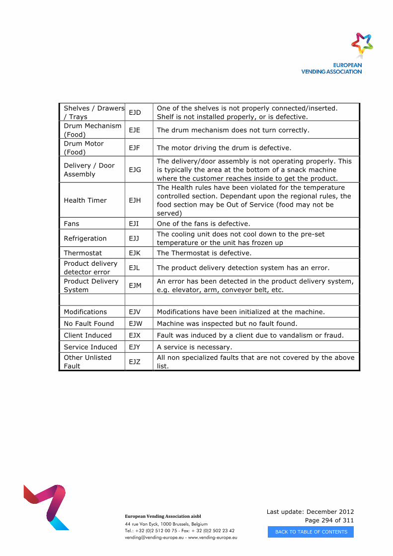
Last update: December 2012 Page 294 of 311
European Vending Association aisbl
44 rue Van Eyck, 1000 Brussels, Belgium Tel.: +32 (0)2 512 00 75 - Fax: + 32 (0)2 502 23 42 [email protected] - www.vending-europe.eu
Shelves / Drawers / Trays EJD One of the shelves is not properly connected/inserted.
Shelf is not installed properly, or is defective. Drum Mechanism (Food)
EJE The drum mechanism does not turn correctly.
Drum Motor (Food) EJF The motor driving the drum is defective.
Delivery / Door Assembly
EJG The delivery/door assembly is not operating properly. This is typically the area at the bottom of a snack machine where the customer reaches inside to get the product.
Health Timer EJH
The Health rules have been violated for the temperature controlled section. Dependant upon the regional rules, the food section may be Out of Service (food may not be served)
Fans EJI One of the fans is defective.
Refrigeration EJJ The cooling unit does not cool down to the pre-set temperature or the unit has frozen up
Thermostat EJK The Thermostat is defective. Product delivery detector error EJL The product delivery detection system has an error.
Product Delivery System EJM An error has been detected in the product delivery system,
e.g. elevator, arm, conveyor belt, etc.
Modifications EJV Modifications have been initialized at the machine.
No Fault Found EJW Machine was inspected but no fault found.
Client Induced EJX Fault was induced by a client due to vandalism or fraud.
Service Induced EJY A service is necessary. Other Unlisted Fault EJZ All non specialized faults that are not covered by the above
list.
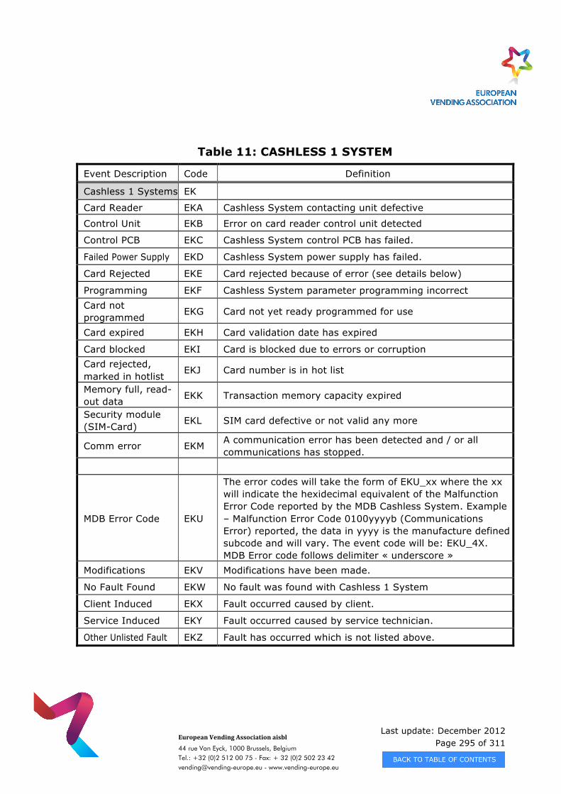
Last update: December 2012 Page 295 of 311
European Vending Association aisbl
44 rue Van Eyck, 1000 Brussels, Belgium Tel.: +32 (0)2 512 00 75 - Fax: + 32 (0)2 502 23 42 [email protected] - www.vending-europe.eu
Table 11: CASHLESS 1 SYSTEM
Event Description Code Definition
Cashless 1 Systems EK
Card Reader EKA Cashless System contacting unit defective
Control Unit EKB Error on card reader control unit detected
Control PCB EKC Cashless System control PCB has failed.
Failed Power Supply EKD Cashless System power supply has failed.
Card Rejected EKE Card rejected because of error (see details below)
Programming EKF Cashless System parameter programming incorrect Card not programmed EKG Card not yet ready programmed for use
Card expired EKH Card validation date has expired
Card blocked EKI Card is blocked due to errors or corruption Card rejected, marked in hotlist
EKJ Card number is in hot list
Memory full, read-out data EKK Transaction memory capacity expired
Security module (SIM-Card) EKL SIM card defective or not valid any more
Comm error EKM A communication error has been detected and / or all communications has stopped.
MDB Error Code EKU
The error codes will take the form of EKU_xx where the xx will indicate the hexidecimal equivalent of the Malfunction Error Code reported by the MDB Cashless System. Example – Malfunction Error Code 0100yyyyb (Communications Error) reported, the data in yyyy is the manufacture defined subcode and will vary. The event code will be: EKU_4X. MDB Error code follows delimiter « underscore »
Modifications EKV Modifications have been made.
No Fault Found EKW No fault was found with Cashless 1 System
Client Induced EKX Fault occurred caused by client.
Service Induced EKY Fault occurred caused by service technician.
Other Unlisted Fault EKZ Fault has occurred which is not listed above.
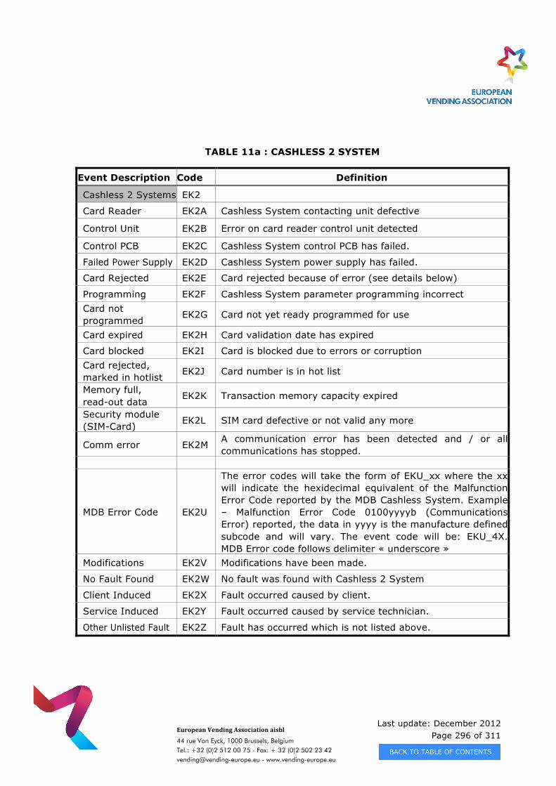
Last update: December 2012 Page 296 of 311
European Vending Association aisbl
44 rue Van Eyck, 1000 Brussels, Belgium Tel.: +32 (0)2 512 00 75 - Fax: + 32 (0)2 502 23 42 [email protected] - www.vending-europe.eu
TABLE 11a : CASHLESS 2 SYSTEM
Event Description Code Definition
Cashless 2 Systems EK2
Card Reader EK2A Cashless System contacting unit defective
Control Unit EK2B Error on card reader control unit detected
Control PCB EK2C Cashless System control PCB has failed.
Failed Power Supply EK2D Cashless System power supply has failed.
Card Rejected EK2E Card rejected because of error (see details below)
Programming EK2F Cashless System parameter programming incorrect Card not programmed EK2G Card not yet ready programmed for use
Card expired EK2H Card validation date has expired
Card blocked EK2I Card is blocked due to errors or corruption Card rejected, marked in hotlist EK2J Card number is in hot list
Memory full, read-out data
EK2K Transaction memory capacity expired
Security module (SIM-Card) EK2L SIM card defective or not valid any more
Comm error EK2M A communication error has been detected and / or all communications has stopped.
MDB Error Code EK2U
The error codes will take the form of EKU_xx where the xx will indicate the hexidecimal equivalent of the Malfunction Error Code reported by the MDB Cashless System. Example – Malfunction Error Code 0100yyyyb (Communications Error) reported, the data in yyyy is the manufacture defined subcode and will vary. The event code will be: EKU_4X. MDB Error code follows delimiter « underscore »
Modifications EK2V Modifications have been made.
No Fault Found EK2W No fault was found with Cashless 2 System
Client Induced EK2X Fault occurred caused by client.
Service Induced EK2Y Fault occurred caused by service technician.
Other Unlisted Fault EK2Z Fault has occurred which is not listed above.
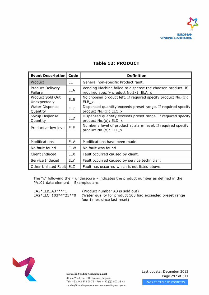
Last update: December 2012 Page 297 of 311
European Vending Association aisbl
44 rue Van Eyck, 1000 Brussels, Belgium Tel.: +32 (0)2 512 00 75 - Fax: + 32 (0)2 502 23 42 [email protected] - www.vending-europe.eu
Table 12: PRODUCT
Event Description Code Definition
Product EL General non-specific Product fault. Product Delivery Failure ELA Vending Machine failed to dispense the choosen product. If
required specify product No.(x): ELA_x Product Sold Out Unexpectedly ELB No choosen product left. If required specify product No.(x):
ELB_x Water Dispense Quantity ELC Dispensed quantity exceeds preset range. If required specify
product No.(x): ELC_x Syrup Dispense Quantity ELD Dispensed quantity exceeds preset range. If required specify
product No.(x): ELD_x
Product at low level ELE Number / level of product at alarm level. If required specify product No.(x): ELE_x
Modifications ELV Modifications have been made.
No fault found ELW No fault was found
Client Induced ELX Fault occurred caused by client.
Service Induced ELY Fault occurred caused by service technician.
Other Unlisted Fault ELZ Fault has occurred which is not listed above.
The “x” following the « underscore » indicates the product number as defined in the PA101 data element. Examples are: EA2*ELB_A3****1 (Product number A3 is sold out) EA2*ELC_103*4*25**0 (Water quality for product 103 had exceeded preset range
four times since last reset)
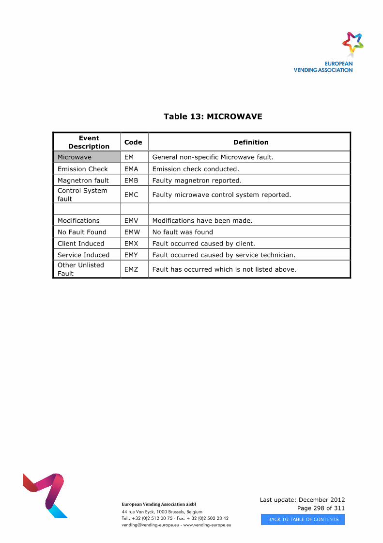
Last update: December 2012 Page 298 of 311
European Vending Association aisbl
44 rue Van Eyck, 1000 Brussels, Belgium Tel.: +32 (0)2 512 00 75 - Fax: + 32 (0)2 502 23 42 [email protected] - www.vending-europe.eu
Table 13: MICROWAVE
Event Description Code Definition
Microwave EM General non-specific Microwave fault.
Emission Check EMA Emission check conducted.
Magnetron fault EMB Faulty magnetron reported. Control System fault EMC Faulty microwave control system reported.
Modifications EMV Modifications have been made.
No Fault Found EMW No fault was found
Client Induced EMX Fault occurred caused by client.
Service Induced EMY Fault occurred caused by service technician. Other Unlisted Fault EMZ Fault has occurred which is not listed above.
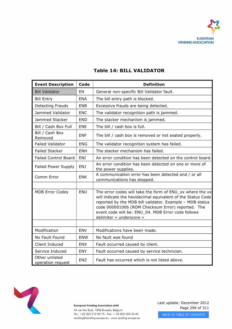
Last update: December 2012 Page 299 of 311
European Vending Association aisbl
44 rue Van Eyck, 1000 Brussels, Belgium Tel.: +32 (0)2 512 00 75 - Fax: + 32 (0)2 502 23 42 [email protected] - www.vending-europe.eu
Table 14: BILL VALIDATOR
Event Description Code Definition
Bill Validator EN General non-specific Bill Validator fault.
Bill Entry ENA The bill entry path is blocked.
Detecting Frauds ENB Excessive frauds are being detected.
Jammed Validator ENC The validator recognition path is jammed.
Jammed Stacker END The stacker mechanism is jammed.
Bill / Cash Box Full ENE The bill / cash box is full. Bill / Cash Box Removed ENF The bill / cash box is removed or not seated properly.
Failed Validator ENG The validator recognition system has failed.
Failed Stacker ENH The stacker mechanism has failed.
Failed Control Board ENI An error condition has been detected on the control board.
Failed Power Supply ENJ An error condition has been detected on one or more of the power supplies.
Comm Error ENK A communication error has been detected and / or all communications has stopped.
MDB Error Codes ENU The error codes will take the form of ENU_xx where the xx
will indicate the hexidecimal equivalent of the Status Code reported by the MDB bill validator. Example – MDB status code 00000100b (ROM Checksum Error) reported. The event code will be: ENU_04. MDB Error code follows delimiter « underscore »
Modification ENV Modifications have been made.
No Fault Found ENW No fault was found
Client Induced ENX Fault occurred caused by client.
Service Induced ENY Fault occurred caused by service technician. Other unlisted operation request ENZ Fault has occurred which is not listed above.
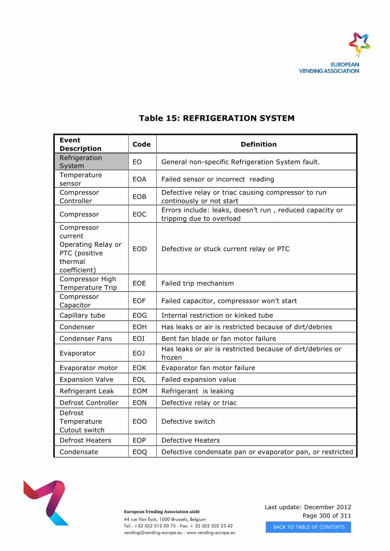
Last update: December 2012 Page 300 of 311
European Vending Association aisbl
44 rue Van Eyck, 1000 Brussels, Belgium Tel.: +32 (0)2 512 00 75 - Fax: + 32 (0)2 502 23 42 [email protected] - www.vending-europe.eu
Table 15: REFRIGERATION SYSTEM
Event Description Code Definition
Refrigeration System EO General non-specific Refrigeration System fault.
Temperature sensor EOA Failed sensor or incorrect reading
Compressor Controller EOB Defective relay or triac causing compressor to run
continously or not start
Compressor EOC Errors include: leaks, doesn’t run , reduced capacity or tripping due to overload
Compressor current Operating Relay or PTC (positive thermal coefficient)
EOD Defective or stuck current relay or PTC
Compressor High Temperature Trip EOE Failed trip mechanism
Compressor Capacitor EOF Failed capacitor, compresssor won’t start
Capillary tube EOG Internal restriction or kinked tube
Condenser EOH Has leaks or air is restricted because of dirt/debries
Condenser Fans EOI Bent fan blade or fan motor failure
Evaporator EOJ Has leaks or air is restricted because of dirt/debries or frozen
Evaporator motor EOK Evaporator fan motor failure
Expansion Valve EOL Failed expansion value
Refrigerant Leak EOM Refrigerant is leaking
Defrost Controller EON Defective relay or triac Defrost Temperature Cutout switch
EOO Defective switch
Defrost Heaters EOP Defective Heaters
Condensate EOQ Defective condensate pan or evaporator pan, or restricted
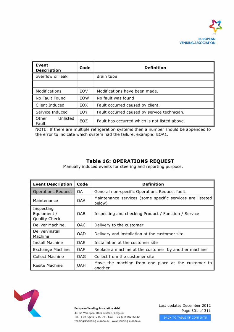
Last update: December 2012 Page 301 of 311
European Vending Association aisbl
44 rue Van Eyck, 1000 Brussels, Belgium Tel.: +32 (0)2 512 00 75 - Fax: + 32 (0)2 502 23 42 [email protected] - www.vending-europe.eu
Event Description Code Definition
overflow or leak drain tube
Modifications EOV Modifications have been made.
No Fault Found EOW No fault was found
Client Induced EOX Fault occurred caused by client.
Service Induced EOY Fault occurred caused by service technician. Other Unlisted Fault EOZ Fault has occurred which is not listed above.
NOTE: If there are multiple refrigeration systems then a number should be appended to the error to indicate which system had the failure, example: EOA1.
Table 16: OPERATIONS REQUEST Manually induced events for steering and reporting purpose.
Event Description Code Definition
Operations Request OA General non-specific Operations Request fault.
Maintenance OAA Maintenance services (some specific services are listeted below)
Inspecting Equipment / Quality Check
OAB Inspecting and checking Product / Function / Service
Deliver Machine OAC Delivery to the customer Deliver/install Machine OAD Delivery and installation at the customer site
Install Machine OAE Installation at the customer site
Exchange Machine OAF Replace a machine at the customer by another machine
Collect Machine OAG Collect from the customer site
Resite Machine OAH Move the machine from one place at the customer to another
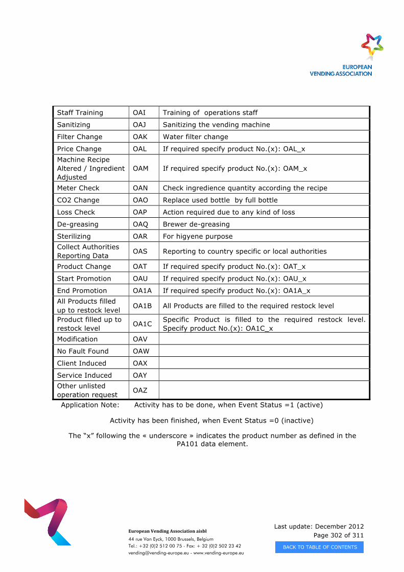
Last update: December 2012 Page 302 of 311
European Vending Association aisbl
44 rue Van Eyck, 1000 Brussels, Belgium Tel.: +32 (0)2 512 00 75 - Fax: + 32 (0)2 502 23 42 [email protected] - www.vending-europe.eu
Staff Training OAI Training of operations staff
Sanitizing OAJ Sanitizing the vending machine
Filter Change OAK Water filter change
Price Change OAL If required specify product No.(x): OAL_x Machine Recipe Altered / Ingredient Adjusted
OAM If required specify product No.(x): OAM_x
Meter Check OAN Check ingredience quantity according the recipe
CO2 Change OAO Replace used bottle by full bottle
Loss Check OAP Action required due to any kind of loss
De-greasing OAQ Brewer de-greasing
Sterilizing OAR For higyene purpose Collect Authorities Reporting Data OAS Reporting to country specific or local authorities
Product Change OAT If required specify product No.(x): OAT_x
Start Promotion OAU If required specify product No.(x): OAU_x
End Promotion OA1A If required specify product No.(x): OA1A_x All Products filled up to restock level OA1B All Products are filled to the required restock level
Product filled up to restock level OA1C Specific Product is filled to the required restock level.
Specify product No.(x): OA1C_x Modification OAV
No Fault Found OAW
Client Induced OAX
Service Induced OAY Other unlisted operation request OAZ
Application Note: Activity has to be done, when Event Status =1 (active)
Activity has been finished, when Event Status =0 (inactive)
The “x” following the « underscore » indicates the product number as defined in the PA101 data element.
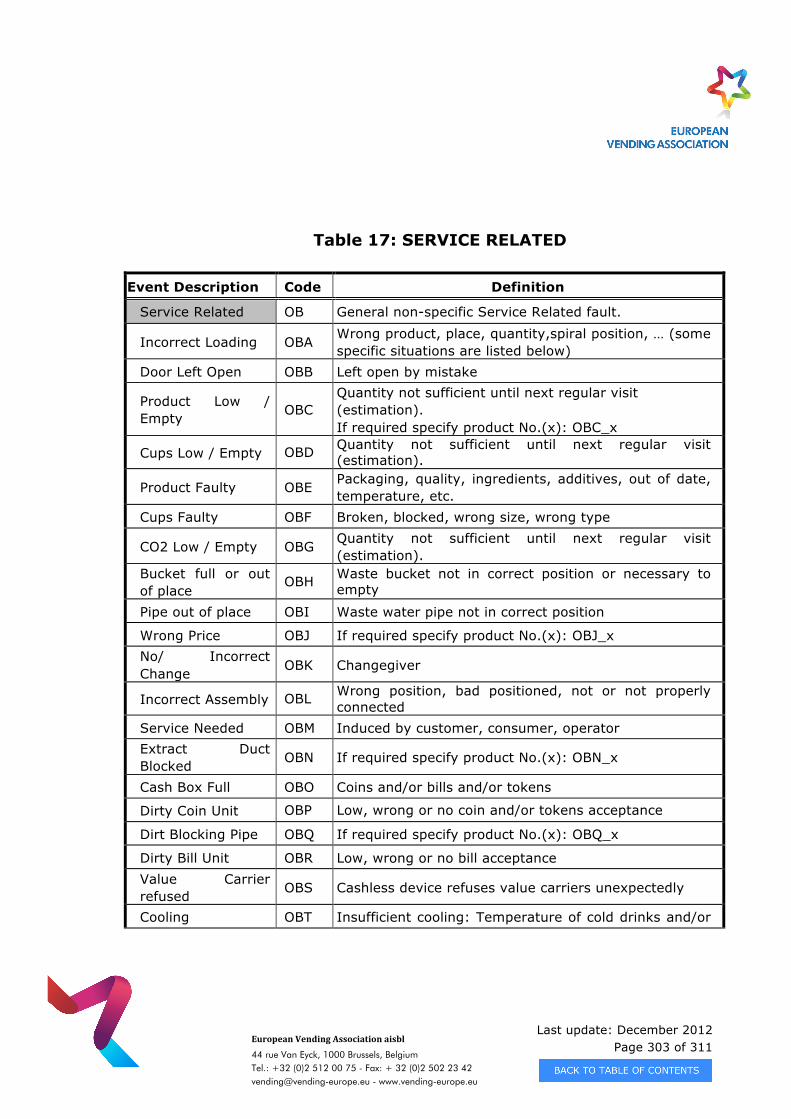
Last update: December 2012 Page 303 of 311
European Vending Association aisbl
44 rue Van Eyck, 1000 Brussels, Belgium Tel.: +32 (0)2 512 00 75 - Fax: + 32 (0)2 502 23 42 [email protected] - www.vending-europe.eu
Table 17: SERVICE RELATED
Event Description Code Definition
Service Related OB General non-specific Service Related fault.
Incorrect Loading OBA Wrong product, place, quantity,spiral position, … (some specific situations are listed below)
Door Left Open OBB Left open by mistake
Product Low / Empty OBC
Quantity not sufficient until next regular visit (estimation). If required specify product No.(x): OBC_x
Cups Low / Empty OBD Quantity not sufficient until next regular visit (estimation).
Product Faulty OBE Packaging, quality, ingredients, additives, out of date, temperature, etc.
Cups Faulty OBF Broken, blocked, wrong size, wrong type
CO2 Low / Empty OBG Quantity not sufficient until next regular visit (estimation).
Bucket full or out of place
OBH Waste bucket not in correct position or necessary to empty
Pipe out of place OBI Waste water pipe not in correct position
Wrong Price OBJ If required specify product No.(x): OBJ_x No/ Incorrect Change OBK Changegiver
Incorrect Assembly OBL Wrong position, bad positioned, not or not properly connected
Service Needed OBM Induced by customer, consumer, operator Extract Duct Blocked OBN If required specify product No.(x): OBN_x
Cash Box Full OBO Coins and/or bills and/or tokens
Dirty Coin Unit OBP Low, wrong or no coin and/or tokens acceptance
Dirt Blocking Pipe OBQ If required specify product No.(x): OBQ_x
Dirty Bill Unit OBR Low, wrong or no bill acceptance Value Carrier refused OBS Cashless device refuses value carriers unexpectedly
Cooling OBT Insufficient cooling: Temperature of cold drinks and/or
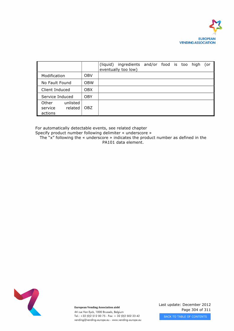
Last update: December 2012 Page 304 of 311
European Vending Association aisbl
44 rue Van Eyck, 1000 Brussels, Belgium Tel.: +32 (0)2 512 00 75 - Fax: + 32 (0)2 502 23 42 [email protected] - www.vending-europe.eu
(liquid) ingredients and/or food is too high (or eventually too low)
Modification OBV
No Fault Found OBW
Client Induced OBX
Service Induced OBY Other unlisted service related actions
OBZ
For automatically detectable events, see related chapter Specify product number following delimiter « underscore »
The “x” following the « underscore » indicates the product number as defined in the PA101 data element.
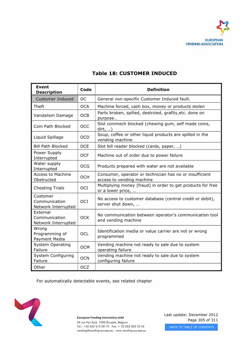
Last update: December 2012 Page 305 of 311
European Vending Association aisbl
44 rue Van Eyck, 1000 Brussels, Belgium Tel.: +32 (0)2 512 00 75 - Fax: + 32 (0)2 502 23 42 [email protected] - www.vending-europe.eu
Table 18: CUSTOMER INDUCED
Event Description Code Definition
Customer Induced OC General non-specific Customer Induced fault.
Theft OCA Machine forced, cash box, money or products stolen
Vandalism Damage OCB Parts broken, spilled, destroied, grafity,etc. done on purpose…
Coin Path Blocked OCC Slot coinmech blocked (chewing gum, self made coins, dirt, …)
Liquid Spillage OCD Soup, coffee or other liquid products are spilled in the vending machine
Bill Path Blocked OCE Slot bill reader blocked (cards, paper, …) Power Supply Interrupted OCF Machine out of order due to power failure
Water supply Interrupted OCG Products prepared with water are not available
Access to Machine Obstructed OCH
Consumer, operator or technician has no or insufficient access to vending machine
Cheating Trials OCI Multiplying money (fraud) in order to get products for free or a lower price, …
Customer Communication Network Interrupted
OCJ No access to customer database (central credit or debit), server shut down, …
External Communication Network Interrupted
OCK No communication between operator’s communication tool and vending machine
Wrong Programming of Payment Media
OCL Identification media or value carrier are not or wrong programmed
System Operating Failure OCM Vending machine not ready to sale due to system
operating failure System Configuring Failure OCN Vending machine not ready to sale due to system
configuring failure Other OCZ
For automatically detectable events, see related chapter
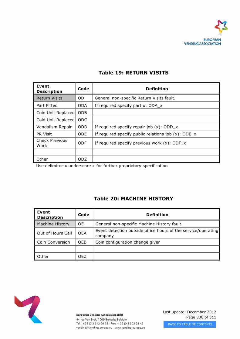
Last update: December 2012 Page 306 of 311
European Vending Association aisbl
44 rue Van Eyck, 1000 Brussels, Belgium Tel.: +32 (0)2 512 00 75 - Fax: + 32 (0)2 502 23 42 [email protected] - www.vending-europe.eu
Table 19: RETURN VISITS
Event Description Code Definition
Return Visits OD General non-specific Return Visits fault.
Part Fitted ODA If required specify part x: ODA_x
Coin Unit Replaced ODB
Cold Unit Replaced ODC
Vandalism Repair ODD If required specify repair job (x): ODD_x
PR Visit ODE If required specify public relations job (x): ODE_x Check Previous Work ODF If required specify previous work (x): ODF_x
Other ODZ Use delimiter « underscore » for further proprietary specification
Table 20: MACHINE HISTORY
Event Description Code Definition
Machine History OE General non-specific Machine History fault.
Out of Hours Call OEA Event detection outside office hours of the service/operating company
Coin Conversion OEB Coin configuration change giver
Other OEZ
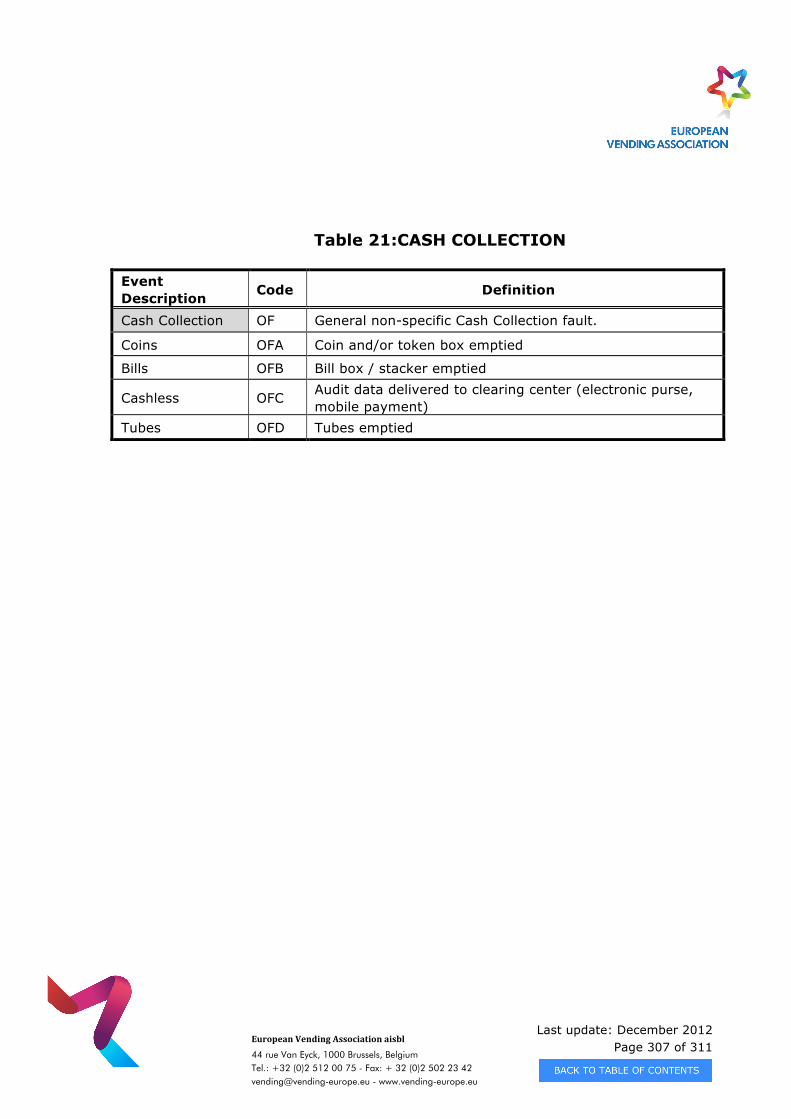
Last update: December 2012 Page 307 of 311
European Vending Association aisbl
44 rue Van Eyck, 1000 Brussels, Belgium Tel.: +32 (0)2 512 00 75 - Fax: + 32 (0)2 502 23 42 [email protected] - www.vending-europe.eu
Table 21:CASH COLLECTION
Event Description Code Definition
Cash Collection OF General non-specific Cash Collection fault.
Coins OFA Coin and/or token box emptied
Bills OFB Bill box / stacker emptied
Cashless OFC Audit data delivered to clearing center (electronic purse, mobile payment)
Tubes OFD Tubes emptied
Last update: December 2012 Page 308 of 311
European Vending Association aisbl
44 rue Van Eyck, 1000 Brussels, Belgium Tel.: +32 (0)2 512 00 75 - Fax: + 32 (0)2 502 23 42 [email protected] - www.vending-europe.eu
C.3. PROCESS FOR MAINTAINING EVENT LIST
The current Event List will be published on the EVA web site.
Request for the creation of new codes should be sent to EVA at :
Each request should have the following information :
Name of Requesting Company
Contact Person
Unit Code – Define which system to which the event is relevant
Definition of the New event – as much detail as possible
Each request will be circulated to the Standards Committee of the EVA and the Technical Working Group of NAMA and a response will be provided within 6 working weeks. If the new Event is defined it will be added to the list maintained on the EVA
web site.
Last update: December 2012 Page 309 of 311
European Vending Association aisbl
44 rue Van Eyck, 1000 Brussels, Belgium Tel.: +32 (0)2 512 00 75 - Fax: + 32 (0)2 502 23 42 [email protected] - www.vending-europe.eu
APPENDIX D - CHANGES
D.1. EXPLANATION OF VERSION 6.1
According to the definitions contained within the standard each release of EVA-DTS is known as a version. Each version consists of a level and a revision number, thus Version 6.1 is equal to level six, revision one.
D.2. PROTOCOL LAYERS AND PHYSICAL LAYERS
Version 6.1 does have only minor corrections in chapter 3
D.3. DATA FORMAT
In chapter 2 new PA7 elements are used instead of PA2 elements in the examples.
D.4. APPLICATION NOTES DATA
In chapter 5 under 5.1.6 the data element format maximum values are now clear defined for the back-office developers. In 5.1.7 the pricelist handling is added and in 5.1.8 the mixed payment is described. In chapter 5.2.4.1 the examples for CA301 and CA305 were corrected.
D.5. DATA DICTIONARY
The Data Dictionary, Appendix A has been completely reviewed and additional clarification made to definitions. For many identifiers the type and lengths were corrected to handle all in a uniform way. Some new elements have been defined.
Last update: December 2012 Page 310 of 311
European Vending Association aisbl
44 rue Van Eyck, 1000 Brussels, Belgium Tel.: +32 (0)2 512 00 75 - Fax: + 32 (0)2 502 23 42 [email protected] - www.vending-europe.eu
In particular, DA1001 to DA1004 for cashless device1 and DB1001 to DB1004 for cashless device2 are defined. To handle the complicated field of cash actions like surcharge, discount, price token the new elements PA701 to PA708 were defined. For mixed payments the elements PA801 to PA804 were defined. The definition of CA303 and CA307 was clarified, it now reads “manually filled” instead of “manual fill modes”.
Last update: December 2012 Page 311 of 311
European Vending Association aisbl
44 rue Van Eyck, 1000 Brussels, Belgium Tel.: +32 (0)2 512 00 75 - Fax: + 32 (0)2 502 23 42 [email protected] - www.vending-europe.eu
APPENDIX E - CHANGE PROCEDURE
The EVA-DTS Standard is maintained and developed jointly by the EVA Standards Committee and the NAMA Technical Standards Committee.
Any comments, requests for assistance or changes should be addressed to either of the following
EUROPEAN VENDING ASSOCIATION (EVA)
Rue Van Eyck 44 1000 Brussels - Belgium
Tel: +32 2 512 00 75 Fax: +32 2 502 23 42
e-mail: [email protected]
NAMA
Headquarters
20 North Wacker Drive, Suite 3500 Chicago, IL 60606-3102 - USA
Tel : +1 312.346.0370 Fax: +1 312.704.4140
e-mail: [email protected]
Dependant on the nature of the request, the issue raised will be forwarded to both of the above working groups.
After consideration of the issue if the request requires a modification to the standard, the activity will be added to the work list for the committees and amendments published in a revised issue of the standard.