evaluating the impact of increasing system fault...
TRANSCRIPT
Evaluating the Impact of Increasing System Fault Currents
on Protection
Ilia Voloh, Zhihan Xu
– GE Grid Solutions
Mohsen Khanbeigi – Hydro One
70th Annual Conference for Protective Relay Engineers
Outline
•Overview of increasing short circuit fault current levels
• Impacts of increased fault levels on protection relays
• Impact evaluation techniques•Case studies
Causes of increasing fault current
• Installa tion of new transmission facilities, transformers and generators
•Additions and changes to existing generators•Reconfigurations of the bulk electric system (BES) network
•New distribution generation
OEB Maximum Allowable Fault Levels
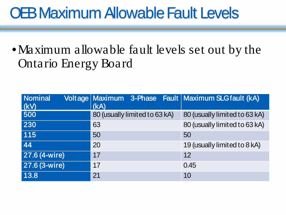
•Maximum allowable fault levels set out by the Ontario Energy Board
Nominal Voltage(kV)
Maximum 3-Phase Fault(kA)
Maximum SLGfault (kA)
500 80 (usually limited to 63 kA) 80 (usually limited to 63 kA)230 63 80 (usually limited to 63 kA)115 50 5044 20 19 (usually limited to 8 kA)27.6 (4-wire) 17 1227.6 (3-wire) 17 0.4513.8 21 10

Hydro One Data
• Maximum fault currents in some major substationsNominal Voltage (kV) Fault Current (up to
kA)500 50.47230 73115 32.69
Nominal Voltage(kV)
1990s (kA) Present (kA)
500 40/63 63/80230 40/50/63 50/63/80115 40/50 40/50/63
• CB interrupting capacity requirement
• Increased by 27% in the last twenty years
Questions from Protection Engineers
• What will be the impact of increasing fault current on protection relays?
• Will relays be reliable or not under such situations?• What are the effects on the dependability and security
of a relay?• How to evaluate a specific application?• How to upgrade relay or adjust relay settings to
increase dependability and security?
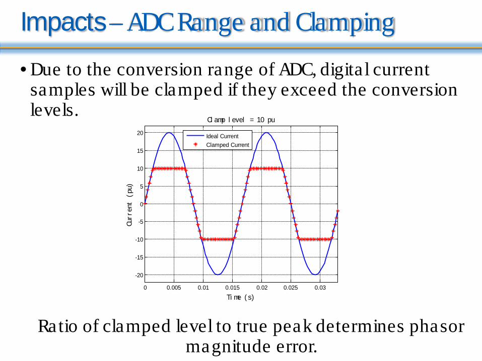
Impacts – ADC Range and Clamping
• Due to the conversion range of ADC, digita l current samples will be clamped if they exceed the conversion levels.
0 0.005 0.01 0.015 0.02 0.025 0.03
-20
-15
-10
-5
0
5
10
15
20
Ti me ( s)
Curr
ent
(pu)
Cl amp l evel = 10 pu
Ideal CurrentClamped Current
Ratio of clamped level to true peak determines phasor magnitude error.
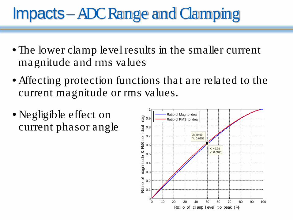
Impacts – ADC Range and Clamping
• The lower clamp level results in the smaller current magnitude and rms values
• Affecting protection functions that are rela ted to the current magnitude or rms values.
0 10 20 30 40 50 60 70 80 90 1000
0.1
0.2
0.3
0.4
0.5
0.6
0.7
0.8
0.9
1
Rat i o of cl amp l evel t o peak ( %)
Rati
o of
mag
nitu
de &
RMS
to
idea
l ma
gX: 49.99Y: 0.6091
X: 49.99Y: 0.6255
Ratio of Mag to IdealRatio of RMS to Ideal
• Negligible effect on current phasor angle

Impacts – ADC Range and Clamping
• Erroneous odd harmonics are induced• For third harmonic, the larger fault current will result in
the larger ra tio of odd harmonics to fundamental magnitude
0 10 20 30 40 50 60 70 80 90 1000
5
10
15
20
25
30
35
Rat i o of cl amp l evel t o peak ( %)
Rati
o of
har
moni
cs t
o fu
ndam
enta
l ma
g (%
)
Third HarmonicFifth HarmonicSeventh HarmonicNinth Harmonic
• The fifth harmonic ra tio may be used to inhibit 87T function during overexcita tion
• No even harmonics induced
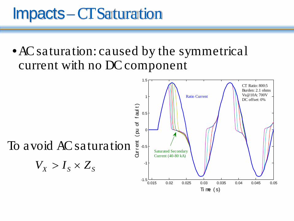
Impacts – CT Saturation
•AC saturation: caused by the symmetrical current with no DC component
SSX ZIV ×>
To avoid AC saturation
0.015 0.02 0.025 0.03 0.035 0.04 0.045 0.05-1.5
-1
-0.5
0
0.5
1
1.5
Ti me ( s)
Curr
ent
(pu
of f
ault
)
Ratio Current
Saturated SecondaryCurrent (40-80 kA)
CT Ratio: 800:5Burden: 2.1 ohmsVs@10A: 700VDC offset: 0%
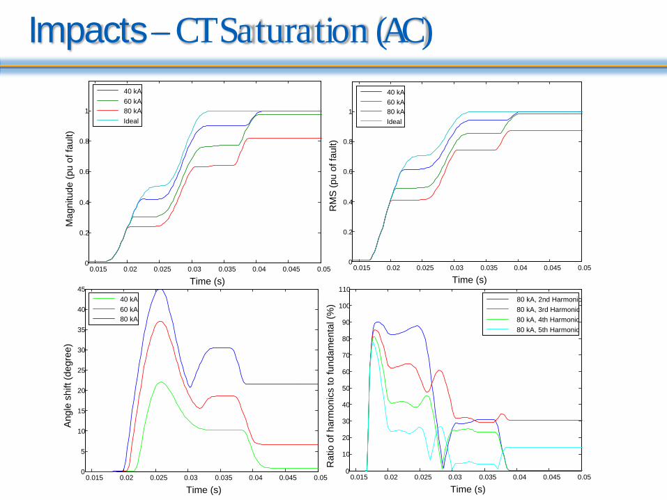
Impacts – CT Saturation (AC)
0.015 0.02 0.025 0.03 0.035 0.04 0.045 0.050
0.2
0.4
0.6
0.8
1
Time (s)
Mag
nitu
de (p
u of
faul
t)
40 kA60 kA80 kAIdeal
0.015 0.02 0.025 0.03 0.035 0.04 0.045 0.050
0.2
0.4
0.6
0.8
1
Time (s)
RM
S (p
u of
faul
t)
40 kA60 kA80 kAIdeal
0.015 0.02 0.025 0.03 0.035 0.04 0.045 0.050
10
20
30
40
50
60
70
80
90
100
110
Time (s)
Rat
io o
f har
mon
ics
to fu
ndam
enta
l (%
)
80 kA, 2nd Harmonic80 kA, 3rd Harmonic80 kA, 4th Harmonic80 kA, 5th Harmonic
0.015 0.02 0.025 0.03 0.035 0.04 0.045 0.050
5
10
15
20
25
30
35
40
45
Time (s)
Ang
le s
hift
(deg
ree)
40 kA60 kA80 kA

Impacts – CT Saturation
•DC saturation: caused by DC component in the fault current , unipolar half wave current or remnant flux in the CT
To avoid DC saturation
)1(RXZIV SSX +××>
0.02 0.03 0.04 0.05 0.06 0.07 0.08
-1
-0.5
0
0.5
1
1.5
2
2.5
Ti me ( s)
Curr
ent
(pu
of f
ault
)
Ratio Current
Saturated SecondaryCurrent (20-80 kA)
CT Ratio: 800:5Burden: 2.1 ohmsVs@10A: 700VDC offset: 100%X/R: 17
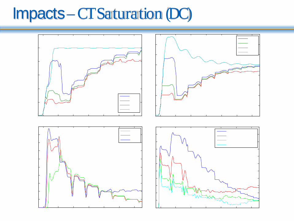
Impacts – CT Saturation (DC)
A
Impacts – CT Saturation
•Reduced magnitude and rms values, which affect current-based protection functions
•Result in the leading angle, which may affect directional functions. o DC saturation will cause more leading angle shift
compared to AC saturation
• Increased ratios of harmonics to fundamental

Evaluation Techniques
•Test in a high current laboratoryo Apply high primary fault current to CT, as the true
fault o Needs special equipment , costly and rarely
available to most users
•Test using a real time power system simulatoro Model the power system, simulate different system
and fault conditions in real time, generate analog signal, which can be applied to a signal amplifier and then injected into input of the relays
o Capacity of the signal amplifier is a major concern for high level secondary fault currents
Evaluation Techniques
•Simulate in electromagnetic transient analysis softwareo Relay model built-in in the s/w: relay performance
can be directly tested by simulating different system and fault conditions
o Relay model not built-in in the s/w : the specific function in a relay can be modeled but requires a lgorithm details and skills.
o Save simulated raw waveforms as COMTRADE files and inject to the relay by using a test set .
o Program analysis software, such as MATLAB, to load raw waveforms, simulate signal processing, model relay functions, and analyze relay response-very complicated.

Evaluation Techniques
•Playback recorded waveformso Analyze the relay performance and corrective
actions by playing back waveforms recorded from a misoperation event due to a heavy fault
•Program in a simple Excel spreadsheeto For example, once the maximum fault level is
determined and CT parameters are known, the PSRC CT saturation calculator can generate the secondary current with saturation or without it , and calculate the fundamental magnitude

Case Studies – 1
• Transformer differentia l relay in a 230/27.6kV substation
230 kV
87T
Zs 27.6 kVLoad
F1 F2 F3
0 1 2 3 4 5 6 7 80
0.5
1
1.5
2
2.5
3
3.5
4
Rest r ai nt Cur r ent ( pu)
Diff
eren
tial
Cur
rent
(pu
)
Percentage 87T SettingsPickup: 0.87 puBreak point: 2puSlope 1: 30%Slope 2: 50%
Unbiased 87T Setting:Pickup: 2.79 pu
OPERATE
RESTRAINT
• Three fault locations a t F1, F2 and F3
• Different fault types
• Two different fault current levels, 60 and 73 kA (F1 point)
• Two fault inception angles, 0 and 90 degree (phase A voltage)
CT: HV 800/5, burden 1.6 ohms
LV 1600/5, burden 1.73 ohmw

Case Studies – 1
• CT saturation example I – SLG fault a t F1
0 0.02 0.04 0.06 0.08 0.1 0.12 0.14 0.16 0.18 0.2-150
-100
-50
0
50
100
150
Ti me ( s)
Satu
rate
d Cu
rren
t (p
u at
HV
side
)
Case Studies – 1
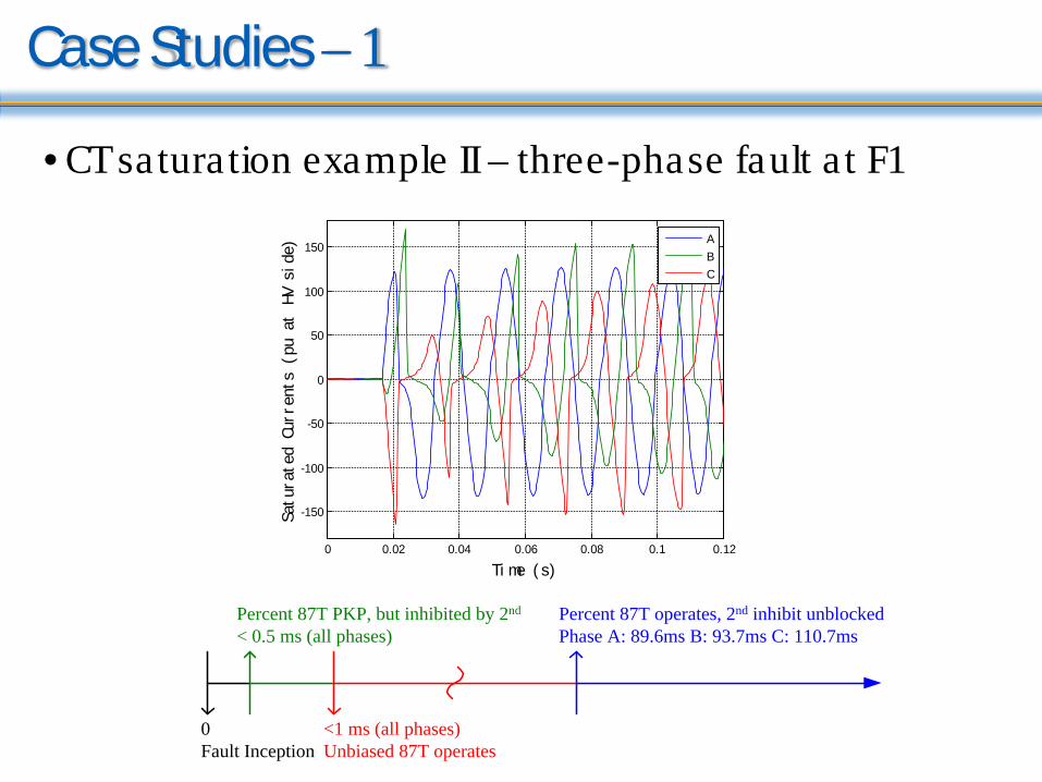
• CT saturation example II – three-phase fault a t F1
0 0.02 0.04 0.06 0.08 0.1 0.12
-150
-100
-50
0
50
100
150
Ti me ( s)
Satu
rate
d Cu
rren
ts (
pu a
t HV
sid
e)
ABC
0 Fault Inception
Percent 87T PKP, but inhibited by 2nd
< 0.5 ms (all phases)
<1 ms (all phases)Unbiased 87T operates
Percent 87T operates, 2nd inhibit unblocked Phase A: 89.6ms B: 93.7ms C: 110.7ms
Case Studies – 1
•Effect of CT saturationo Percentage differentia l function does not have
fa ilure to operate for internal faults or misoperations for external faults (studied case only)
o The instantaneous (unbiased) differentia l protection function should be enabled to avoid a slow operation, if the percentage differentia l function can be potentia lly blocked by the second harmonic inhibit

Case Studies – 1
• Effect of clamping levels, with 10pu pickup setting
0 0.01 0.02 0.03 0.04 0.05 0.06-100
-80
-60
-40
-20
0
20
40
60
80
100
Ti me ( s)
Curr
ents
(pu
at
HV s
ide)
Secondary CurrentClamped Current (32pu)Clamped Current (64pu)
0 0.01 0.02 0.03 0.04 0.05 0.060
5
10
15
20
25
30
35
40
Ti me ( s)Di
ffer
enti
al C
urre
nts
(pu)
X: 0.0151Y: 10.2
X: 0.02578Y: 10.02
Clamped by 32puClamped by 64pu
• Unbiased 87T clamped by 32pu will be slower by 10.68ms
Case Studies – 1
•Results:o In the studied substation, the existing CT and relay
settings are able to handle the increased fault current level, when both biased and unbiased differentia l elements are enabled.
o The increased fault level has effect on the operate time of the biased differentia l function, but this can be mitigated by proper setting of the unbiased differentia l function.

Case Studies – 2
•A 100MVA Yd11 transformer in a 138/19.5kV substation
•Similar fault scenarioso Internal and external faultso Fault levels: 50 and 65 kAo Clamping levels: 32 and 64 pu
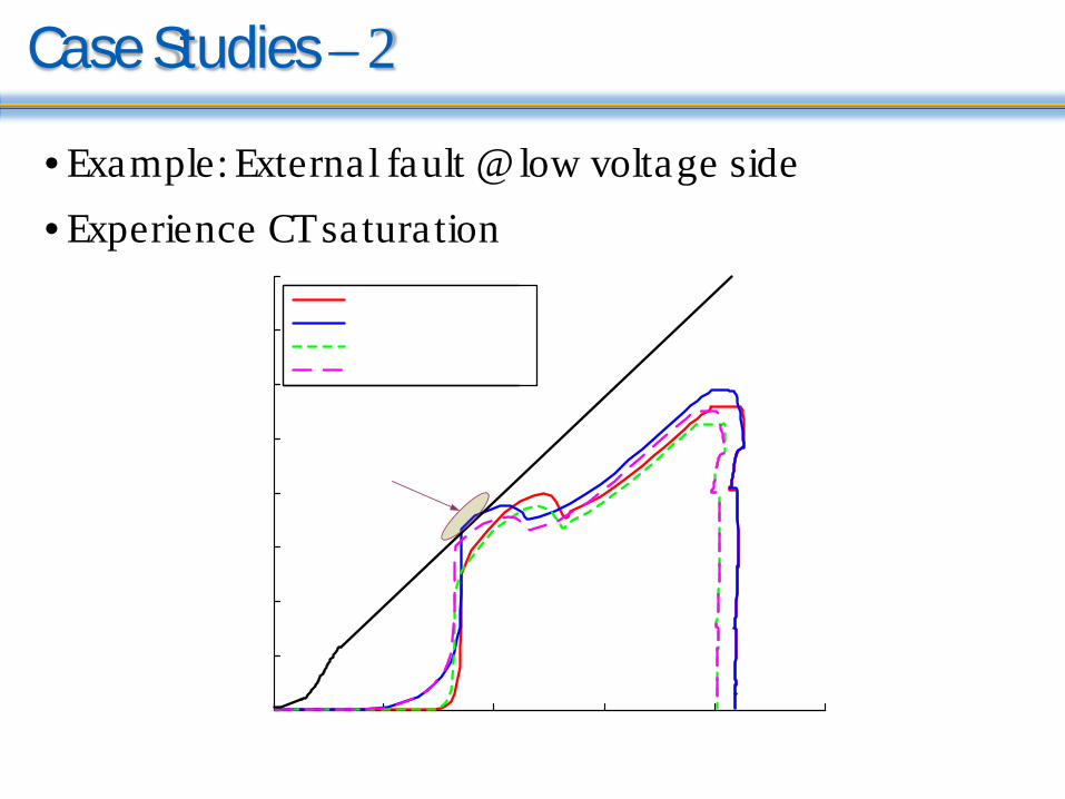
Case Studies – 2
• Example: External fault @ low voltage side• Experience CT saturation
0 5 10 15 20 25
0
2
4
6
8
10
12
14
16
Restraint Current (pu)
Differential Current (pu)
65kA - 64pu Clamping
65kA - 32pu Clamping
50kA - 64pu Clamping
50kA - 32pu Clamping
Misoperation due to increased fault current and lower clamping level

Conclusions
•CT saturation would reduce the magnitude and cause a leading phase angle shift of the current phasor
•Relay internal clamping level limits the measurement range of waveforms, therefore, the calculated magnitudes are decreased potentially endangering differential function and erroneous harmonics are generated
Conclusions
•By analyzing 87T function, o Always enable the unbiased differentia l function to
avoid slow operation due to the inrush inhibit of the percentage differentia l function, thereby improving the relay dependability
o The security of the percentage differentia l function may be jeopardized due to the increased fault current and lower clamping level. The security can be ensured by increasing the differentia l settings or by employing dedicated CT saturation function available in the relay.
o The 87T function with the larger clamping level is typically able to respond faster.

Thank You
Questions?