evaluation-board issue 01.2019 for edip-series · the lands j8 are directly connected with the...
TRANSCRIPT

EVALUATION-BOARDfor eDIP-series
Issue 01.2019
Zeppelinstr. 19 · D-82205 Gilching · Phone +49-(0)8105-778090 · Fax +49-(0)8105-778099 · www.lcd-module.de · [email protected]
TECHNICAL DATA* EVALUATION BOARD DESIGNED FOR SHORTEST DEVELOPMENT TIME* USB-INTERFACE TO CONNECT DIRECTLY YOUR PC; NO EXTRA SUPPLY NEEDED* BUTTONS, LEDS AND POTENTIOMETERS TO INTERFACE IN- AND OUTPUTS OF THE
DISPLAYS* LEDS TO SHOW DATA TRAFFIC* WIDE VOLTAGE RANGE +3.3V..+5V* INCL. USB-CABLE* BEEPER AS FEEDBACK FOR TOUCH* OPTIONAL ADAPTER BOARD EA 9777-2PE EXPANDS TO ALL INTERFACES:
* „REAL“ RS-232 * “MICROCONTROLLER“ RS-232 (CMOS-LEVEL)* RS-485 * SPI (CMOS-LEVEL)* I²C (CMOS-LEVEL)
ORDERING CODESSTARTERKITSINCLUDES: Display incl. Touch + EA 9777-3USB + EA 9777-2PE + DVD + USB-Cable* EA eDIP320B-8LWTP (320x240 dots, blue/white negative) EA EVALeDIP320B* EA eDIP320J-8LWTP (320x240 dots, black/white positive) EA EVALeDIP320J
INCLUDES: Display incl. Touch + EA 9777-3USB + EA 9777-2PE + AC adaptor + DVD + USB-Cable* EA eDIPTFT70-ATP (800x480 dots, 16-Bit color) EA EVALeDIPTFT70* EA eDIPTFT57-ATP (640x480 dots, 16-Bit color) EA EVALeDIPTFT57
SPARE PARTSEVALUATION BOARD FOR USB (WIN2000/XP/VISTA/7 32+64 bit) EA X9777-3USBPORT-EXPANSION (RS-232, I2C, SPI, RS485) FOR EA 9777-2USB EA X9777-2PEMOUNTING FLAP FOR EA eDIPTFT70 (2PCS. REQUIRED) EA CARREDIPTFT04
PERFECT
DEVELOPMENT TOOL!

EA 9777-3Page 2
ELECTRONIC ASSEMBLY reservesthe right to change specificationswithout prior notice. Printing andtypographical errors reserved.
Documentation of revision
Date Type Old New Reason / Description
2011-05-16 0.1 preliminary version
2011-09-14 1.0 First release
CONTENT
QUICK START ........................................................................................................................ 3
EA 9777-3 EVALUATIONBOARD ........................................................................................... 5
FUNCTION OF POTENTIOMETER ........................................................................................ 5
FUNCTION OF JUMPER, PUSHBUTTONS, LEDs............................................................. 6-7
USB-INTERFACE ................................................................................................................... 7
POWER SUPPLY.................................................................................................................... 8
PORT EXPANSION EA 9777-2PE.......................................................................................... 8
DESCRIPTION PIN CONNECTOR I²C (EA 9777-3USB) ...................................................... 9
FUNCTION OF DIP-SWITCH I²C (EA 9777-2PE)................................................................... 9
DESCRIPTION PIN CONNECTOR RS232, RS485 (EA 9777-3USB) ................................. 10
FUNCTION OF DIP-SWITCH RS232, RS485 (EA 9777-2PE) ............................................. 11
DESCRIPTION PIN CONNECTOR SPI (EA 9777-3USB) .................................................... 11
FUNCTION OF DIP-SWITCH SPI (EA 9777-2PE) ............................................................... 11
TROUBLESHOOTING .......................................................................................................... 12
SCHEMATIC 9777-2PE ........................................................................................................ 15
SCHEMATIC 9777-3USB ..................................................................................................... 16
EA 9777-3Page 3
ELECTRONIC ASSEMBLY reservesthe right to change specificationswithout prior notice. Printing andtypographical errors reserved.
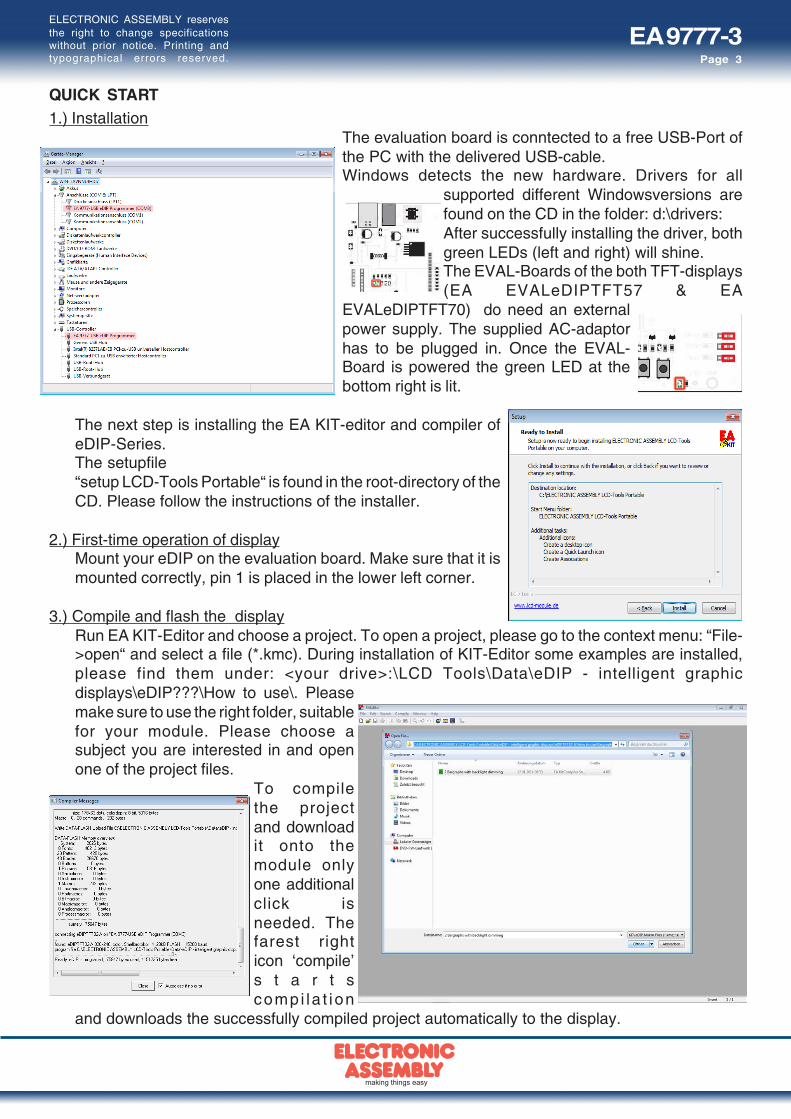
QUICK START1.) Installation
The evaluation board is conntected to a free USB-Port ofthe PC with the delivered USB-cable.Windows detects the new hardware. Drivers for all
supported different Windowsversions arefound on the CD in the folder: d:\drivers:After successfully installing the driver, bothgreen LEDs (left and right) will shine.The EVAL-Boards of the both TFT-displays(EA EVALeDIPTFT57 & EA
EVALeDIPTFT70) do need an externalpower supply. The supplied AC-adaptorhas to be plugged in. Once the EVAL-Board is powered the green LED at thebottom right is lit.
The next step is installing the EA KIT-editor and compiler ofeDIP-Series.The setupfile“setup LCD-Tools Portable“ is found in the root-directory of theCD. Please follow the instructions of the installer.
2.) First-time operation of displayMount your eDIP on the evaluation board. Make sure that it ismounted correctly, pin 1 is placed in the lower left corner.
3.) Compile and flash the displayRun EA KIT-Editor and choose a project. To open a project, please go to the context menu: “File->open“ and select a file (*.kmc). During installation of KIT-Editor some examples are installed,please find them under: <your drive>:\LCD Tools\Data\eDIP - intelligent graphicdisplays\eDIP???\How to use\. Pleasemake sure to use the right folder, suitablefor your module. Please choose asubject you are interested in and openone of the project files.
To compilethe projectand downloadit onto themodule onlyone additionalclick isneeded. Thefarest righticon ‘compile’s t a r t scompi la t ion
and downloads the successfully compiled project automatically to the display.

EA 9777-3Page 4
ELECTRONIC ASSEMBLY reservesthe right to change specificationswithout prior notice. Printing andtypographical errors reserved.
4.) Useful tool “EA LCD Terminal“After starting the terminal (from EA KIT-editor: the second icon from the right) a dialog
is shown with all present serial interfaces.Please choose the onelabeled with “x: eDIPProgrammer (COMx)“. TheEvaluation board has thebaudrate 115200. Pleaseactivate the Small-Protocol(Shift+F8) to exchange data
and commands with the display.
5.) Useful tool “EA BitmapEdit“The EA BitmapEdit is a simple image processing program. It’s designed to use with
the eDIP-Series, it can save and load allformats (e.g. *.g16, *.BH7) of EA eDIP-Series.In addition, you can create elementaryanimations, by dragging the singlepictures onto the editor.
6.) Useful tool “EA Instrument Editor“The EA eDIPTFT-Series is able to show analogue pointer instruments. To create
those instruments you have to use this editor.

EA 9777-3Page 5
ELECTRONIC ASSEMBLY reservesthe right to change specificationswithout prior notice. Printing andtypographical errors reserved.
EA 9777-3USB EVALUATIONBOARD
The Evaluation board provides a variety of features, starting with LEDs to indicate data-transfer,ending with potentiometers to use the analogue inputs of EA eDIPTFTs.The lands J8 are directly connected with the corresponding pin of the eDIP. If you remove the 0R-resistors the periphery is completly disconnected. Please refer to the schematic on the last page.Note: Not all functions of the Evaluation board are supported by every display of the eDIP-series.
FUNCTION OF POTENTIOMETERBoth potentiometers are connected to the anolgueinputs of the eDIPTFTs. They set the voltage of AIN1and AIN2 between GND and VDD.

EA 9777-3Page 6
ELECTRONIC ASSEMBLY reservesthe right to change specificationswithout prior notice. Printing andtypographical errors reserved.
FUNCTION OF JUMPERS- “Disable Power On Macro“: If a continuous loop is programmed
either in PowerOn-, Reset-, Watchdog- or BrownOut-Macro, thedisplay is no longer adressable. In this case you have to restrain therun of Power-On-Macro. This is done by the jumper: Switch poweroff, set the jumper to the right (DPOM to GND). Now you have to re-power the module and release the jumper or set it to the left (DPOMis open).
- “Disable Protocol“: The small-protocol can be disabled. This mightbe helpful espacially in the early stage of development. It is stronglyrecommended to activate the protocol in series, to monitor data-transfer. If the jumper is set to the left, the protocol is deactivated(DPROT to GND). If the jumper is set to the right or left open, theprotocol is activated (DPROT open). You have to reset the moduleif you want to change the protocol-mode.
- “Testmode“: Each eDIP includes a testmode, which can beactivated with the help of a jumper: Set the jumper to the left (TESTto GND) and a test screen will be displayed. If you want to changeto normal operation you have to release the jumper or set it to theright (TEST open) and reset the module.
FUNCTION OF LEDS- “USB-Power“ (green): This LED indicates a connected USB-cable.- “VDD power“ (green): This LED indicates the Evaluation board to be power-supplied- “USB-TxD“ (red): This LED indicates data is transferd to the eDIP.- “USB-RxD“ (green): This LED indicates data is send by the eDIP.- “SBUF“ (orange): This LED glows if data is present in the sendbuffer of the display (SBUF low).- “Output 1-8“ (green): These
LEDs are directly connected tothe outputs of the eDIPTFT. Theyare lit if the output of eDIPTFT isset to high. The EA eDIP320-8has no outputs, so this function isnot available.
Testmode on
Protocol off
DPOM active
EA 9777-3Page 7
ELECTRONIC ASSEMBLY reservesthe right to change specificationswithout prior notice. Printing andtypographical errors reserved.
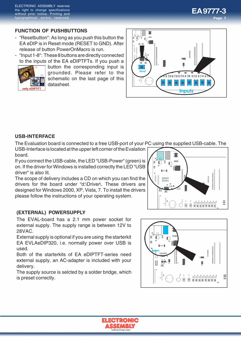
USB-INTERFACEThe Evaluation board is connected to a free USB-port of your PC using the supplied USB-cable. TheUSB-Interface is located at the upper left corner of the Evalationboard.If you connect the USB-cable, the LED “USB-Power“ (green) ison. If the driver for Windows is installed correctly the LED “USBdriver“ is also lit.The scope of delivery includes a CD on which you can find thedrivers for the board under “d:\Driver\. These drivers aredesigned for Windows 2000, XP, Vista, 7. To install the driversplease follow the instructions of your operating system.
FUNCTION OF PUSHBUTTONS- “Resetbutton“: As long as you push this button the
EA eDIP is in Reset mode (RESET to GND). Afterrelease of button PowerOnMacro is run.
- “Input 1-8“: These 8 buttons are directly connectedto the inputs of the EA eDIPTFTs. If you push a
button the corresponding input isgrounded. Please refer to theschematic on the last page of thisdatasheet.
(EXTERNAL) POWERSUPPLYThe EVAL-board has a 2.1 mm power socket forexternal supply. The supply range is between 12V to28VAC.External supply is optional if you are using the starterkitEA EVLAeDIP320, i.e. normally power over USB isused.Both of the starterkits of EA eDIPTFT-series needexternal supply, an AC-adapter is included with yourdelivery.The supply source is selcted by a solder bridge, whichis preset correctly.
EA 9777-3Page 8
ELECTRONIC ASSEMBLY reservesthe right to change specificationswithout prior notice. Printing andtypographical errors reserved.
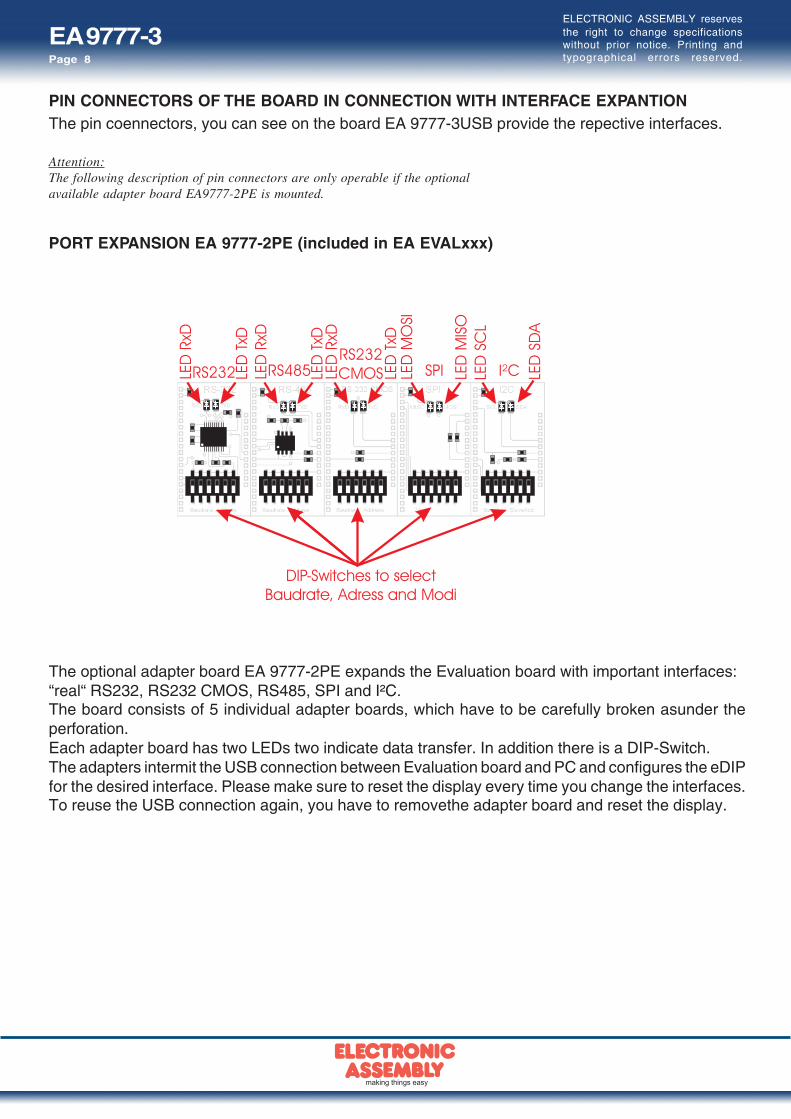
PORT EXPANSION EA 9777-2PE (included in EA EVALxxx)
The optional adapter board EA 9777-2PE expands the Evaluation board with important interfaces:“real“ RS232, RS232 CMOS, RS485, SPI and I²C.The board consists of 5 individual adapter boards, which have to be carefully broken asunder theperforation.Each adapter board has two LEDs two indicate data transfer. In addition there is a DIP-Switch.The adapters intermit the USB connection between Evaluation board and PC and configures the eDIPfor the desired interface. Please make sure to reset the display every time you change the interfaces.To reuse the USB connection again, you have to removethe adapter board and reset the display.
PIN CONNECTORS OF THE BOARD IN CONNECTION WITH INTERFACE EXPANTIONThe pin coennectors, you can see on the board EA 9777-3USB provide the repective interfaces.
Attention:The following description of pin connectors are only operable if the optionalavailable adapter board EA9777-2PE is mounted.
EA 9777-3Page 9
ELECTRONIC ASSEMBLY reservesthe right to change specificationswithout prior notice. Printing andtypographical errors reserved.
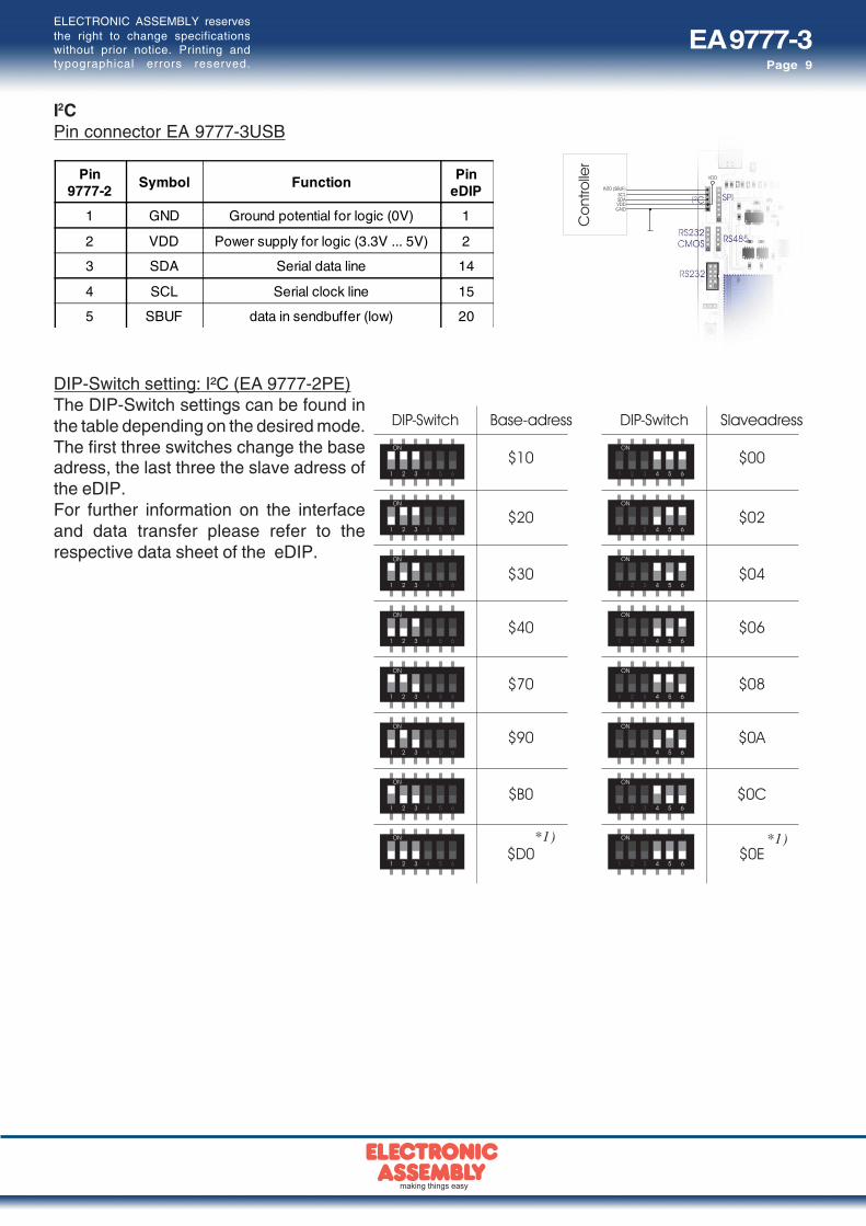
DIP-Switch setting: I²C (EA 9777-2PE)The DIP-Switch settings can be found inthe table depending on the desired mode.The first three switches change the baseadress, the last three the slave adress ofthe eDIP.For further information on the interfaceand data transfer please refer to therespective data sheet of the eDIP.
I2CPin connector EA 9777-3USB
Pin9777-2
Symbol Function PineDIP
1 GND Ground potential for logic (0V) 1
2 VDD Power supply for logic (3.3V ... 5V) 2
3 SDA Serial data line 14
4 SCL Serial clock line 15
5 SBUF data in sendbuffer (low) 20
*1) *1)

EA 9777-3Page 10
ELECTRONIC ASSEMBLY reservesthe right to change specificationswithout prior notice. Printing andtypographical errors reserved.
RS232 CMOS
Pin9777-2
Symbol Function PineDIP
1 GND Ground potential for logic (0V) 1
2 VDD Power supply for logic (3.3V ... 5V) 2
3 RxD Receive data 10
4 TxD Transmit data 11
5 SBUF data in sendbuffer (low) 20
RS485
Pin9777-2
Symbol Function PineDIP
1 GND Ground potential for logic (0V) 1
2 VDD Power supply for logic (3.3V ... 5V) 2
3 A RS485 A (Data +) ---
4 B RS485 B (Data -) ---
5 SBUF data in sendbuffer (low) 20
RS232 +/-12V
Pin9777-2
Symbol Function PineDIP
1 VDD Power supply for logic (3.3V ... 5V) 2
2 DCD ---
3 DSR ---
4 TxD Transmit Data [11]
5 CTS ---
6 RxD Receive Data [10]
7 RTS ---
8 DTR ---
9 NC. Not connected ---
10 GND 1
Note:There is a interface cable available underordering code EA KV24-9B. It allows adirect connection to a PC. The length of thecable is 1.5m.
Pin connector EA 9777-3USB
Pin connector EA 9777-3USB
Pin connector EA 9777-3USB
EA 9777-3Page 11
ELECTRONIC ASSEMBLY reservesthe right to change specificationswithout prior notice. Printing andtypographical errors reserved.
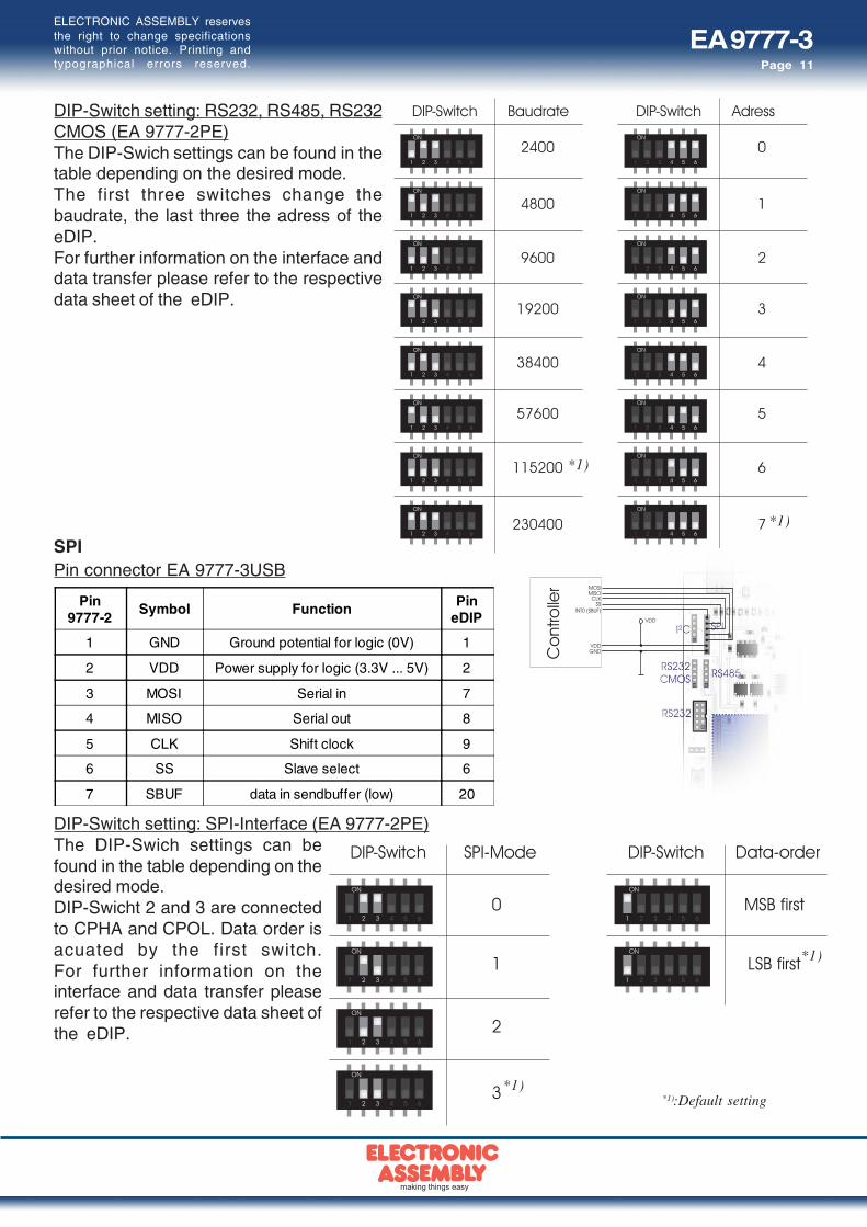
Pin9777-2
Symbol Function PineDIP
1 GND Ground potential for logic (0V) 1
2 VDD Power supply for logic (3.3V ... 5V) 2
3 MOSI Serial in 7
4 MISO Serial out 8
5 CLK Shift clock 9
6 SS Slave select 6
7 SBUF data in sendbuffer (low) 20
DIP-Switch setting: RS232, RS485, RS232CMOS (EA 9777-2PE)The DIP-Swich settings can be found in thetable depending on the desired mode.The first three switches change thebaudrate, the last three the adress of theeDIP.For further information on the interface anddata transfer please refer to the respectivedata sheet of the eDIP.
SPI
DIP-Switch setting: SPI-Interface (EA 9777-2PE)The DIP-Swich settings can befound in the table depending on thedesired mode.DIP-Swicht 2 and 3 are connectedto CPHA and CPOL. Data order isacuated by the first switch.For further information on theinterface and data transfer pleaserefer to the respective data sheet ofthe eDIP.
Pin connector EA 9777-3USB
*1)
*1)
*1)
*1)
*1):Default setting

EA 9777-3Page 12
ELECTRONIC ASSEMBLY reservesthe right to change specificationswithout prior notice. Printing andtypographical errors reserved.
TROUBLESHOOTING- Display not flashing:
Please check the power supply. The LED (Power-LED), placed on the lower right corner hasto glow green. If you supply with USB the solder bridge “Select power“ must be positioned onthe left and the driver for Windows must be installed. If you supply externally, please set thesolder bridge to the right.
- No connection to USB:Check the installation of the USB-driver, with the help of device manager of Windows. Inaddition make sure, that no board of the Port-Expansion (EA 9777-2PE) adaptors aremounted. Please reset the display after removing the adaptor-board.
- No connectin to RS232 (+/-12V):Please check if you have installed the adaptor-board of Interface Expansion EA 9777-2PEcorrectly and reset the display. Also check the wiring of RS232 between your PC and the boardEA 9777-3USB. There is a interface cable available under ordering code EA KV24-9B. Itallows a direct connection to a PC. The length of the cable is 1.5m. If there is still a problem,please have a look on the DIP-Switches, which set the baudrate and adress. It’srecommended to use the defaults. Further information you will find on pages 10 and 11.
- No connection to RS232 (CMOS):Please check if you have installed the adaptor-board of Interface Expansion EA 9777-2PEcorrectly and reset the display. Also check the wiring of RS232 between your controller andthe board EA 9777-3USB. If there is still a problem, please have a look on the DIP-Switches,which set the baudrate and adress. It’s recommended to use the defaults. Further informationcan be found on pages 10 and 11.
- No connection to RS485 (CMOS):Please check if you have installed the adaptor-board of Interface Expansion EA 9777-2PEcorrectly and reset the display. Also check the wiring of RS485 between your controller, theother stations and the board EA 9777-3USB. If there is still a problem, please have a look onthe DIP-Switches, which set the baudrate and adress. It’s recommended to use the defaults.Further information can be found on pages 10 and 11.
- No connection to SPI:Please check if you have installed the adaptor-board of Interface Expansion EA 9777-2PEcorrectly and reset the display. Also check the wiring of SPI between your controller, the otherstations and the board EA 9777-3USB. If there is still a problem, please have a look on the DIP-Switches, which set the baudrate and adress. It’s recommanded to use the defaults. Furtherinformation can be found on page 11.
- No connection to I²C:Please check if you have installed the adaptor-board of Interface Expansion EA 9777-2PEcorrectly and reset the display. Also check the wiring of I²C between your controller, the otherstations and the board EA 9777-3USB. If there is still a problem, please have a look on the DIP-Switches, which set the baudrate and adress. It’s recommended to use the defaults. Furtherinformation can be found on page 11.
EA 9777-3Page 13
ELECTRONIC ASSEMBLY reservesthe right to change specificationswithout prior notice. Printing andtypographical errors reserved.
NOTES

EA 9777-3Page 14
ELECTRONIC ASSEMBLY reservesthe right to change specificationswithout prior notice. Printing andtypographical errors reserved.
NOTES

EA 9777-3Page 15
ELECTRONIC ASSEMBLY reservesthe right to change specificationswithout prior notice. Printing andtypographical errors reserved.
SCHEMATIC 9777-2PE
EA 9777-3Page 16
Zeppelinstr. 19 · D-82205 Gilching · Phone +49-(0)8105-778090 · Fax +49-(0)8105-778099 · www.lcd-module.de · [email protected]
ELECTRONIC ASSEMBLY reservesthe right to change specificationswithout prior notice. Printing andtypographical errors reserved.
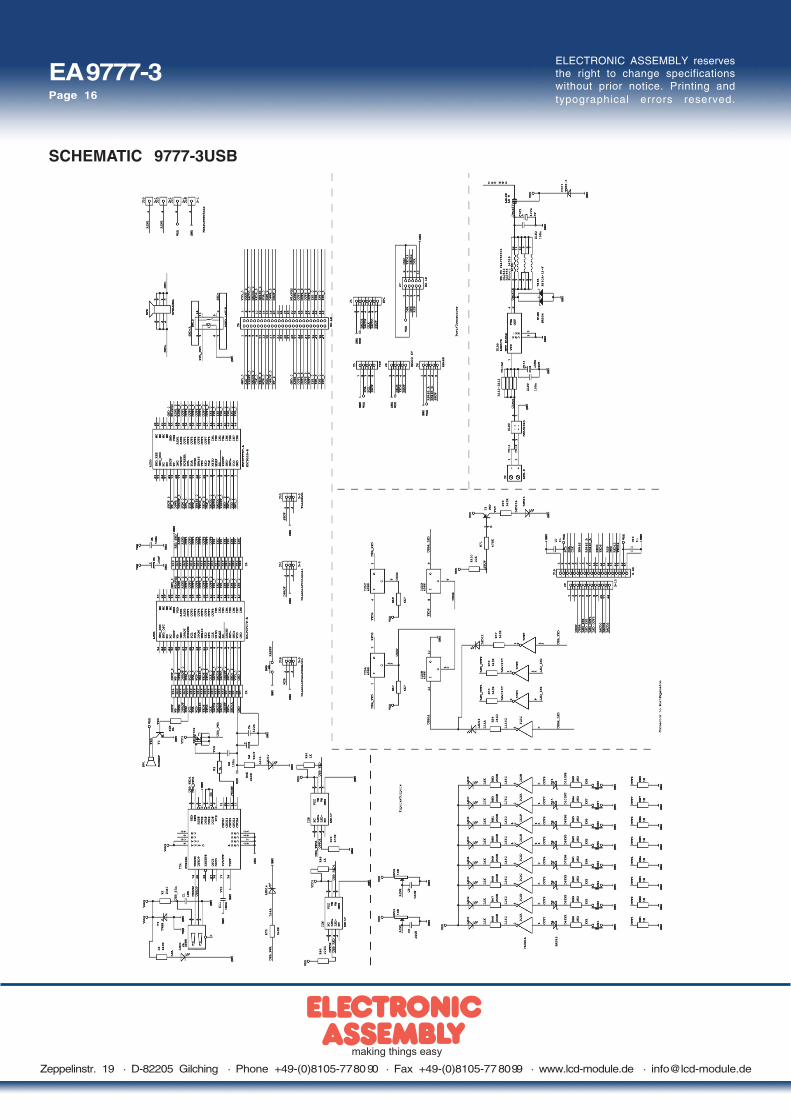
SCHEMATIC 9777-3USB