evaluation of a cable-driven parallel robot: accuracy
TRANSCRIPT

HAL Id: hal-03338533https://hal.archives-ouvertes.fr/hal-03338533
Submitted on 8 Sep 2021
HAL is a multi-disciplinary open accessarchive for the deposit and dissemination of sci-entific research documents, whether they are pub-lished or not. The documents may come fromteaching and research institutions in France orabroad, or from public or private research centers.
L’archive ouverte pluridisciplinaire HAL, estdestinée au dépôt et à la diffusion de documentsscientifiques de niveau recherche, publiés ou non,émanant des établissements d’enseignement et derecherche français ou étrangers, des laboratoirespublics ou privés.
Evaluation of a Cable-Driven Parallel Robot: Accuracy,Repeatability and Long-Term RunningMarceau Métillon, Nicolò Pedemonte, Stéphane Caro
To cite this version:Marceau Métillon, Nicolò Pedemonte, Stéphane Caro. Evaluation of a Cable-Driven Parallel Robot:Accuracy, Repeatability and Long-Term Running. In: Gouttefarde M., Bruckmann T., Pott A. (eds)Cable-Driven Parallel Robots. CableCon 2021. Mechanisms and Machine Science, 104, Springer,pp.375-388, 2021, 10.1007/978-3-030-75789-2_30. hal-03338533
Evaluation of a Cable-Driven Parallel Robot:
Accuracy, Repeatability and Long-Term
Running
Marceau Metillon1,2, Nicolo Pedemonte3, and Stephane Caro1,2
1 Laboratoire des Sciences du Numerique de Nantes (LS2N), UMR CNRS 6004,1, rue de la Noe, 44321 Nantes, France
marceau.metillon,[email protected] Centre National de la Recherche Scientifique (CNRS),
1, rue de la Noe, 44321 Nantes, France3 IRT Jules Verne, Chemin du Chaffault, 44340, Bouguenais, France
Abstract. The performance evaluation of Cable-Driven Parallel Robotsin terms of accuracy, repeatability and long term capacities is a keyfor their industrial deployment. This paper presents and analyses corre-sponding experimental results for the PACE prototype, a fully-constrained,redundantly restrained, eight cables and six degrees of freedom cable-driven parallel robot. First, a long-term running test is carried out toevaluate the deviation of the moving-platform pose along time of use. Asecond experiment consists into a full design of experiments to evaluatethe effect of some factors specific to this type of robot on its absoluteaccuracy and repeatability. Experimental results are presented and dis-cussed.
Keywords: parallel robot · cable · accuracy · repeatability · long-termrunning
1 Introduction
Several industrial sectors, e.g. the naval and renewable energy industries, arefacing with the necessity to manufacture and manipulate large and complexshape products. Cable-Driven Parallel Robots (CDPRs) are suitable for this typeof application thanks to their high payload-to-weight ratio, large workspace andreconfiguration capabilities.
CDPRs are a particular class of parallel robots whose moving-platform (MP)is connected to the robot fixed base frame by a number of cables. The cablesare coiled on motorized winches which control the cable lengths. The cablesare routed from the winches to the MP through pulleys. The connection pointsbetween the cables and the base frame are referred to as exit points and arelocated on the exit pulleys and the connection points between the cables andthe MP are referred to as anchor points.

2 Metillon M., Pedemonte, N. and Caro S.
The knowledge of the accuracy and repeatability of CDPRs is a key feature toguarantee their correct fitting to the industrial task they are assigned to. Variousapproaches are proposed to improve the accuracy of CDPRs such as the use ofadditional sensors and data fusion. In [5,6], cable angle measurement sensorsare used in a sensor fusion to improve the MP pose accuracy. In [8], a fusionof data from a camera and three laser distance sensors is used as a feedback ina closed-loop Cartesian pose controller. In [10], various combinations of sensormeasurements such as IMU and cable angle are studied while in [12], cabletension sensors are used to simplify and solve the analytical Direct Kinematic(DK) problem of CDPRs. In [13], the estimation of the MP mass and payloadusing cable tension is studied. In [18] various algorithms and filters are consideredin IMU-sensors fusion for solving the DK problem of a Gough-Stewart platform.In [11], three lidars are embedded on the MP during long-term running of aCDPR and are used to correct the Cartesian MP pose.
The use of elastic cable models also increases the robot accuracy. In [17], theuse of a simple elastic cable model is implemented and experimentations exhibitan improved position accuracy. In [2], the use of an elasto-dynamic model ofa non-redundant CDPR is studied in term of position accuracy improvement.In [14], the stiffness of the robot is studied and a Stiffness Oriented Tension Dis-tribution Algorithm reduces the deviation of the MP under external wrenches.Exteroceptive vision-based control algorithms also contribute to the improve-ment of CDPR accuracy. In [4], a 3D pose kinematic visual servoing and avision-based computed torque control were implemented for the control of aCDPR. In [3], a vision is used to track the robot position using tracked visualfeatures placed on the MP and an external fixed camera. In [20], a 2 ½D vi-sual servoing is studied and implemented experimentally on a CDPR to increaseits robustness to manufacturing and calibration errors as well as to improve itsaccuracy.
Once designed and manufactured, an experimental evaluation allows one todetermine the prototype accuracy and repeatability performances. In [15] thelong-term running of a CDPR printer was analyzed. After a week of continuousrunning the joint lag was measured exhibiting the cable creep. In [7] the positionaccuracy of a three-dof CDPR performing dynamic trajectories was evaluatedusing an external vision tracking system. In [16], the vertical position error ofa cable-based robotic crane were determined, a distribution of position errorsalong horizontal axes was also described and analysed. Others techniques can beused to increase CDPR accuracy. In [1], a Neural Network uses IMU sensor datato control the robot and images taken by an embedded camera are used to closethe control loop. In [9], the cable elasticity is taken into account in the fusion ofdata from embedded IMU and encoder information.
In this paper, the accuracy and repeatability of a CDPR prototype, namedPACE and located at IRT Jules Verne, are analyzed experimentally throughlong-term running. Furthermore a full factorial design of experiments is run toevaluate the effect of factors specific to CDPRs on the MP pose accuracy andrepeatability. The paper is organized as follows: Section 2 presents the experi-
Accuracy, Repeatability and Long Term running of a CDPR 3
mental setup considered in this work. Section 3 describes the method and showsthe results obtained with the long-term experiment. Section 4 presents the full-factorial design of experiments and the obtained results. Conclusions and futurework are drawn in Sec 5.
2 Experimental setup
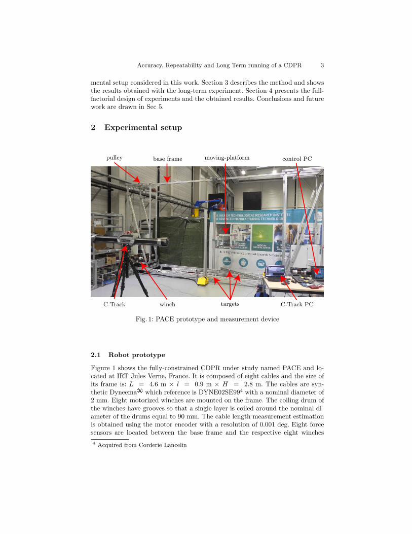
pulley base frame moving-platform control PC
C-Track winch targets C-Track PC
Fig. 1: PACE prototype and measurement device
2.1 Robot prototype
Figure 1 shows the fully-constrained CDPR under study named PACE and lo-cated at IRT Jules Verne, France. It is composed of eight cables and the size ofits frame is: L = 4.6 m × l = 0.9 m × H = 2.8 m. The cables are syn-thetic Dyneema® which reference is DYNE02SE994 with a nominal diameter of2 mm. Eight motorized winches are mounted on the frame. The coiling drum ofthe winches have grooves so that a single layer is coiled around the nominal di-ameter of the drums equal to 90 mm. The cable length measurement estimationis obtained using the motor encoder with a resolution of 0.001 deg. Eight forcesensors are located between the base frame and the respective eight winches
4 Acquired from Corderie Lancelin

4 Metillon M., Pedemonte, N. and Caro S.
in order to measure the cable tensions. Cables are routed through pulleys andconnected to the vertex of a parallelepiped aluminium profile MP. Two controlcabinets are mounted on each side of the frame and connect all the motors andneeded equipment such as motors drivers, sensors, power supply and communi-cation devices. A control PC is located in the switching cabinets. Using a remoteconnexion, it is possible to control the robot and download recorded data fromthe robot controller PC.
2.2 Exteroceptive measurement
A dynamic tracking module VXtrack along with a C-Track™ measuring devicefrom Creaform are used to measure the MP pose. The device is composed of aset of two cameras mounted on a support and connected to a controller com-municating with a computer for data acquisition. Self-adhesive circular dots, ofdiameter equal to 20 mm, called targets are placed on the rigid main frame of therobot and identified as reference targets. The latter are used to define the globalframe. Targets are also placed on the MP and on a faceted 3D-printed spherefixed to the MP. They are identified as tracked targets and are used to measurethe MP pose in the global frame of the robot at a rate of 30 Hz. The measure-ment repeatability and accuracy are equal to 0.02 mm and 0.1 mm, respectivelywithin a 16 m3 measurement volume.
3 Long-term running experiments
The long-term running evaluation of the robot refers to the evaluation of thedeviation of the MP pose during long-term on-duty and off-duty periods of therobot. The MP deviation amounts to the MP absolute accuracy, namely thedifference between the desired MP pose and the measured MP pose.
3.1 Method
In this experiment, the robot is controlled using a classical closed-loop position-based joint-space control. The desired trajectory motion described in operationalspace is converted into a set of joint coordinates using the Inverse GeometricModel (IGM) of the robot. A Feed-Forward model determines the needed jointtorques to fulfil the static and dynamic equilibrium of the MP along the tra-jectory. In addition to this open-loop control architecture a feedback controlleruses joint position information to compute a correcting torque to ensure thetrajectory tracking without error between the desired trajectory and the tra-jectory followed by the robot in the joint space. The difference between jointposition measurement and desired joint position (the joint error) is used in aproportionnal-integral-derivative (PID) feedback controller.
A path5 alternating translation and orientation movements of the MP wasspecifically defined for the long-term running experiments and is shown in Fig-
5 Here is a link to the trajectory followed by the CDPR MP during long-term experi-ments: https://metillon.net/CableCon2021

Accuracy, Repeatability and Long Term running of a CDPR 5
FbFbFbFbFbFbFbFbFbFbFbFbFbFbFbFbFbFbFbFbFbFbFbFbFbFbFbFbFbFbFbFbFbFbFbFbFbFbFbFbFbFbFbFbFbFbFbFbFbFbFbFbFbFbFbFbFbFbFbFbFbFbFbFbFbFbFbFbFbFbFbFbFbFbFbFbFbFbFbFbFbFbFbFbFbFbFbFbFbFbFbFbFbFbFbFbFbFbFbFbFb
PAPAPAPAPAPAPAPAPAPAPAPAPAPAPAPAPAPAPAPAPAPAPAPAPAPAPAPAPAPAPAPAPAPAPAPAPAPAPAPAPAPAPAPAPAPAPAPAPAPAPAPAPAPAPAPAPAPAPAPAPAPAPAPAPAPAPAPAPAPAPAPAPAPAPAPAPAPAPAPAPAPAPAPAPAPAPAPAPAPAPAPAPAPAPAPAPAPAPAPAPA
P2P2P2P2P2P2P2P2P2P2P2P2P2P2P2P2P2P2P2P2P2P2P2P2P2P2P2P2P2P2P2P2P2P2P2P2P2P2P2P2P2P2P2P2P2P2P2P2P2P2P2P2P2P2P2P2P2P2P2P2P2P2P2P2P2P2P2P2P2P2P2P2P2P2P2P2P2P2P2P2P2P2P2P2P2P2P2P2P2P2P2P2P2P2P2P2P2P2P2P2P2
PBPBPBPBPBPBPBPBPBPBPBPBPBPBPBPBPBPBPBPBPBPBPBPBPBPBPBPBPBPBPBPBPBPBPBPBPBPBPBPBPBPBPBPBPBPBPBPBPBPBPBPBPBPBPBPBPBPBPBPBPBPBPBPBPBPBPBPBPBPBPBPBPBPBPBPBPBPBPBPBPBPBPBPBPBPBPBPBPBPBPBPBPBPBPBPBPBPBPBPBPB
P1P1P1P1P1P1P1P1P1P1P1P1P1P1P1P1P1P1P1P1P1P1P1P1P1P1P1P1P1P1P1P1P1P1P1P1P1P1P1P1P1P1P1P1P1P1P1P1P1P1P1P1P1P1P1P1P1P1P1P1P1P1P1P1P1P1P1P1P1P1P1P1P1P1P1P1P1P1P1P1P1P1P1P1P1P1P1P1P1P1P1P1P1P1P1P1P1P1P1P1P1
FMPFMPFMPFMPFMPFMPFMPFMPFMPFMPFMPFMPFMPFMPFMPFMPFMPFMPFMPFMPFMPFMPFMPFMPFMPFMPFMPFMPFMPFMPFMPFMPFMPFMPFMPFMPFMPFMPFMPFMPFMPFMPFMPFMPFMPFMPFMPFMPFMPFMPFMPFMPFMPFMPFMPFMPFMPFMPFMPFMPFMPFMPFMPFMPFMPFMPFMPFMPFMPFMPFMPFMPFMPFMPFMPFMPFMPFMPFMPFMPFMPFMPFMPFMPFMPFMPFMPFMPFMPFMPFMPFMPFMPFMPFMPFMPFMPFMPFMPFMPFMP
PE1PE1PE1PE1PE1PE1PE1PE1PE1PE1PE1PE1PE1PE1PE1PE1PE1PE1PE1PE1PE1PE1PE1PE1PE1PE1PE1PE1PE1PE1PE1PE1PE1PE1PE1PE1PE1PE1PE1PE1PE1PE1PE1PE1PE1PE1PE1PE1PE1PE1PE1PE1PE1PE1PE1PE1PE1PE1PE1PE1PE1PE1PE1PE1PE1PE1PE1PE1PE1PE1PE1PE1PE1PE1PE1PE1PE1PE1PE1PE1PE1PE1PE1PE1PE1PE1PE1PE1PE1PE1PE1PE1PE1PE1PE1PE1PE1PE1PE1PE1PE1
PE2PE2PE2PE2PE2PE2PE2PE2PE2PE2PE2PE2PE2PE2PE2PE2PE2PE2PE2PE2PE2PE2PE2PE2PE2PE2PE2PE2PE2PE2PE2PE2PE2PE2PE2PE2PE2PE2PE2PE2PE2PE2PE2PE2PE2PE2PE2PE2PE2PE2PE2PE2PE2PE2PE2PE2PE2PE2PE2PE2PE2PE2PE2PE2PE2PE2PE2PE2PE2PE2PE2PE2PE2PE2PE2PE2PE2PE2PE2PE2PE2PE2PE2PE2PE2PE2PE2PE2PE2PE2PE2PE2PE2PE2PE2PE2PE2PE2PE2PE2PE2
PE3PE3PE3PE3PE3PE3PE3PE3PE3PE3PE3PE3PE3PE3PE3PE3PE3PE3PE3PE3PE3PE3PE3PE3PE3PE3PE3PE3PE3PE3PE3PE3PE3PE3PE3PE3PE3PE3PE3PE3PE3PE3PE3PE3PE3PE3PE3PE3PE3PE3PE3PE3PE3PE3PE3PE3PE3PE3PE3PE3PE3PE3PE3PE3PE3PE3PE3PE3PE3PE3PE3PE3PE3PE3PE3PE3PE3PE3PE3PE3PE3PE3PE3PE3PE3PE3PE3PE3PE3PE3PE3PE3PE3PE3PE3PE3PE3PE3PE3PE3PE3
PE4PE4PE4PE4PE4PE4PE4PE4PE4PE4PE4PE4PE4PE4PE4PE4PE4PE4PE4PE4PE4PE4PE4PE4PE4PE4PE4PE4PE4PE4PE4PE4PE4PE4PE4PE4PE4PE4PE4PE4PE4PE4PE4PE4PE4PE4PE4PE4PE4PE4PE4PE4PE4PE4PE4PE4PE4PE4PE4PE4PE4PE4PE4PE4PE4PE4PE4PE4PE4PE4PE4PE4PE4PE4PE4PE4PE4PE4PE4PE4PE4PE4PE4PE4PE4PE4PE4PE4PE4PE4PE4PE4PE4PE4PE4PE4PE4PE4PE4PE4PE4
~xb~xb~xb~xb~xb~xb~xb~xb~xb~xb~xb~xb~xb~xb~xb~xb~xb~xb~xb~xb~xb~xb~xb~xb~xb~xb~xb~xb~xb~xb~xb~xb~xb~xb~xb~xb~xb~xb~xb~xb~xb~xb~xb~xb~xb~xb~xb~xb~xb~xb~xb~xb~xb~xb~xb~xb~xb~xb~xb~xb~xb~xb~xb~xb~xb~xb~xb~xb~xb~xb~xb~xb~xb~xb~xb~xb~xb~xb~xb~xb~xb~xb~xb~xb~xb~xb~xb~xb~xb~xb~xb~xb~xb~xb~xb~xb~xb~xb~xb~xb~xb
~yb~yb~yb~yb~yb~yb~yb~yb~yb~yb~yb~yb~yb~yb~yb~yb~yb~yb~yb~yb~yb~yb~yb~yb~yb~yb~yb~yb~yb~yb~yb~yb~yb~yb~yb~yb~yb~yb~yb~yb~yb~yb~yb~yb~yb~yb~yb~yb~yb~yb~yb~yb~yb~yb~yb~yb~yb~yb~yb~yb~yb~yb~yb~yb~yb~yb~yb~yb~yb~yb~yb~yb~yb~yb~yb~yb~yb~yb~yb~yb~yb~yb~yb~yb~yb~yb~yb~yb~yb~yb~yb~yb~yb~yb~yb~yb~yb~yb~yb~yb~yb~zb~zb~zb~zb~zb~zb~zb~zb~zb~zb~zb~zb~zb~zb~zb~zb~zb~zb~zb~zb~zb~zb~zb~zb~zb~zb~zb~zb~zb~zb~zb~zb~zb~zb~zb~zb~zb~zb~zb~zb~zb~zb~zb~zb~zb~zb~zb~zb~zb~zb~zb~zb~zb~zb~zb~zb~zb~zb~zb~zb~zb~zb~zb~zb~zb~zb~zb~zb~zb~zb~zb~zb~zb~zb~zb~zb~zb~zb~zb~zb~zb~zb~zb~zb~zb~zb~zb~zb~zb~zb~zb~zb~zb~zb~zb~zb~zb~zb~zb~zb~zb
~xp~xp~xp~xp~xp~xp~xp~xp~xp~xp~xp~xp~xp~xp~xp~xp~xp~xp~xp~xp~xp~xp~xp~xp~xp~xp~xp~xp~xp~xp~xp~xp~xp~xp~xp~xp~xp~xp~xp~xp~xp~xp~xp~xp~xp~xp~xp~xp~xp~xp~xp~xp~xp~xp~xp~xp~xp~xp~xp~xp~xp~xp~xp~xp~xp~xp~xp~xp~xp~xp~xp~xp~xp~xp~xp~xp~xp~xp~xp~xp~xp~xp~xp~xp~xp~xp~xp~xp~xp~xp~xp~xp~xp~xp~xp~xp~xp~xp~xp~xp~xp
~yp~yp~yp~yp~yp~yp~yp~yp~yp~yp~yp~yp~yp~yp~yp~yp~yp~yp~yp~yp~yp~yp~yp~yp~yp~yp~yp~yp~yp~yp~yp~yp~yp~yp~yp~yp~yp~yp~yp~yp~yp~yp~yp~yp~yp~yp~yp~yp~yp~yp~yp~yp~yp~yp~yp~yp~yp~yp~yp~yp~yp~yp~yp~yp~yp~yp~yp~yp~yp~yp~yp~yp~yp~yp~yp~yp~yp~yp~yp~yp~yp~yp~yp~yp~yp~yp~yp~yp~yp~yp~yp~yp~yp~yp~yp~yp~yp~yp~yp~yp~yp~zp~zp~zp~zp~zp~zp~zp~zp~zp~zp~zp~zp~zp~zp~zp~zp~zp~zp~zp~zp~zp~zp~zp~zp~zp~zp~zp~zp~zp~zp~zp~zp~zp~zp~zp~zp~zp~zp~zp~zp~zp~zp~zp~zp~zp~zp~zp~zp~zp~zp~zp~zp~zp~zp~zp~zp~zp~zp~zp~zp~zp~zp~zp~zp~zp~zp~zp~zp~zp~zp~zp~zp~zp~zp~zp~zp~zp~zp~zp~zp~zp~zp~zp~zp~zp~zp~zp~zp~zp~zp~zp~zp~zp~zp~zp~zp~zp~zp~zp~zp~zp
Fig. 2: Test path, targets and MP home poses
ure 2. The path is composed of four segments passing through the waypoints PE1,PE2, PE3 and PE4. The Cartesian coordinates of these four points expressed inthe global frame Fb are the following :
pE1 = [1.000, 0.346, 0.400]T m (1)
pE2 = [1.500, 0.346, 1.200]T m (2)
pE3 = [3.200, 0.346, 1.400]T m (3)
pE4 = [2.800, 0.346, 0.800]T m (4)
The orientation of the MP remains constant once the MP translates. The MPperforms pure rotations at points PB and PD. Accordingly, the test-trajectoryis as follows:
1. Starting at point PE1, translation to point PE2.2. Rotation of the MP of +5 deg then -3 deg around axis ~xb, +5 deg then
-5 deg around axis ~yb and +5 deg then -5 deg around axis ~zb successivelywhile staying at position PE2
3. Translation from PE2 to PE4 via PE3
4. Rotation of the MP of +5 deg then -3 deg around axis ~xb, +5 deg then-5 deg around axis ~yb and +5 deg then -5 deg around axis ~zb successivelywhile staying at position PE4
5. Translation from PE4 to PE1
6. Pause of 10 seconds at point PE1
This trajectory is running on a loop all along the experiment. The MP velocityfollows a trapezoidal profile along each segment and the maximum velocity is1 m/s. One loop takes 40 s to complete.

6 Metillon M., Pedemonte, N. and Caro S.
At the beginning of the experiment, the robot is calibrated at its home poseonce and is then controlled to reach the initial point of the specific trajectory.At this point a first measurement of the MP pose is performed and is used asa reference for further measurements. From this point, the robot is expected towork three 8-hour work sessions on three different days without re-calibration.During a session, the robot repeats the trajectory on a loop during the wholesession. At each iteration of the loop, the robot does stop during ten secondsat the initial point. This allows the exteroceptive measurement of the MP poseafter settling of dynamic vibrations.
During sessions, three measurements are performed namely at the beginning,at the middle and at the end of the session. At the end of the session, once themeasurement is made, the trajectory is stopped and the MP remains at the initialpose of the trajectory. The robot is then safely shut down using the brakes andstandard procedure awaiting next session. At the beginning of the next session,the robot is powered on. The MP pose is measured in order to determine thestatic deviation occurring during the off duty period between the two sessions.Then the same procedure is repeated as per the first session for the second andthird sessions.
3.2 Long-term running experimental results
At the end of the experiment, nine pose measurements of the MP were recordedcorresponding to the beginning, the middle and the end of all three sessions asshown in Figure 3. The boxes represent the working session (namely on-duty)and the part of the graph outside the boxes represents the periods when the MPwas held in position at initial point and not moving (namely off-duty).
By analyzing the different MP pose measurements it is possible to distin-guish two different deviations. One is referred to as dynamic deviation which isaccumulated during running hours of the robot, the other is referred to as staticdeviation and consists into the deviation added up during off-duty periods. Fig-ure 3 shows the static and dynamic position and orientation deviations of theMP along time on the overall experiment. Figure 4 describes the part of thedeviation obtained during on-duty and off-duty periods. The results exhibit acreep phenomenon of the cable during off-duty periods. As far as we understand,this is mainly due the MP mass exerting cable tensions and thus a permanentelongation of the cables. The opposite sign in the deviations comes from theroutine used to stop the robot at the end of each running period. The trajectoryis stopped when the robot comes back to the initial pose. The measurement atthe end of the day is performed then the brakes are activated and the driversstopped. Once the off duty period is over, in the beginning of the next runningperiod, the robot is powered on by activating drivers and then releasing thebrakes while servoing the motors on the current position.

Accuracy, Repeatability and Long Term running of a CDPR 7
0 20 40 60 80 100 120 140−4
−3
−2
−1
0
1
2
Time (h)
Positiondev
iation(m
m)
TX
TY
TZ
(a) Translational displacement
0 20 40 60 80 100 120 140−0.2
−0.1
0
0.1
0.2
0.3
Time (h)
Orien
tationdev
iation(deg)
RX
RY
RZ
(b) Rotational displacement
Fig. 3: MP pose deviation along the three eight-hour sessions and during restperiods (Total time = 120h = 5 days)
X Y Z Norm−6
−4
−2
0
2
4
6
8
Positiondev
iation(m
m)
Static
Dynamic
X Y Z Norm−0.2
−0.1
0
0.1
0.2
0.3
0.4
Orien
tationdev
iation(deg)
Fig. 4: Static and dynamic MP position and orientation deviations

8 Metillon M., Pedemonte, N. and Caro S.
4 Accuracy and repeatability
This section aims to evaluate the absolute accuracy and repeatability of the pro-totype. The absolute accuracy is the capability of the robot to position its MP ata desired pose. The repeatability is the ability of the robot to repeatedly return tothe same location under the same program with the same conditions [19]. More-over, this section aims to determine the influence of factors specific to CDPR onthe accuracy and repeatability of the MP pose.
4.1 Method
In order to identify the specific influence of each factor, a full factorial designof experiments is considered over the two-levels of each factor. The consideredfactors are the following : cable tension, home MP pose, elasticity and payload.Each factor has two-levels as described in Table 1.
Table 1: Full factorial design factors
factors low level (-1) high level (1)
cable tension 50N 28Nhome MP pose p1 = [2.177, 0.349, 1.083]T m p2 = [2.127, 0.423, 0.017]T m
elasticity without withpayload without (0 kg) with (8 kg)
Considering the four factors, the full factorial design of experiment has 24 =16 different experiments. In order to take into account the repeatability, allexperiments are repeated five times. Therefore 80 experiments are carried outin a randomised order.
4.2 Factors
The home MP pose factor defines the pose where the MP is calibrated. Twodifferent calibration poses are considered, the first pose, named P1, is locatedaround the centre of the robot workspace while the second, named P2 is locatedat the bottom of the robot workspace. The cable tension factor corresponds tothe initial cable tension set. The initial cable tension is the parameter definingthe amount of tension given to the cable during the calibration phase. Duringthe calibration procedure, the MP is located at its home pose then the initialcable tension is gradually applied simultaneously to all cables. This ensures acertain pre-tension in the cable. Two sets are defined, each yielding the sameinitial cable tension for all cables. The elasticity factor defines whether the cableelasticity compensation algorithm of the prototype is used for the experimentor not. The cable elasticity compensation algorithm aims to compensate thecable elongation under the cable tension due to its elasticity. Using the cable

Accuracy, Repeatability and Long Term running of a CDPR 9
tension and length information, a linear elastic cable model is used to determinethe cable elongation, which is then used in the robot geometric model so thatthe desired cable length accounts for the elongation. The elasticity of the cablewas identified experimentally such that ES = 121 775.96 N. The payload factorcorresponds to the presence or the absence of the payload on the MP.
4.3 Experimental procedure
Two points of interest, known as target points, called PA and PB whose coor-dinates expressed in the base frame Fb are pA = [1.000, 0.346, 0.400]T m andpB = [3.200, 0.346, 1.400]T m are defined in the robot workspace. The poseof the MP is to be evaluated at these two points and compared to the desiredpose. The accuracy can then be expressed as the mean of the error between thedesired and measured poses over the five repetitions of a given experiment. Therepeatability is the standard deviation of the error over the repetitions. For eachexperiment, the procedure is the following:
1. The platform is placed on the calibration point corresponding to the home
MP pose factor (P1 or P2).2. The load corresponding to the payload factor is mounted on the platform
(with or without).3. The elasticity algorithm is set corresponding to the elasticity factor (with or
without).4. The initial cable tension set corresponding to the cable tension factor (high
or low) is gradually applied to the cables in increments of 25% of the finalvalue.
5. The robot reaches the target PA and waits.6. The MP pose is measured using the C-Track™ measurement system.7. The robot reaches the target PB and waits.8. The MP pose is measured using the C-Track™ measurement system.9. The robot measurements are recorded.10. The MP returns to the calibration point.
In this experiment, the control architecture is close to the one used in Sec. 3.The only difference lies in the cable elasticity compensation algorithm used,which is a function of the state of the cable elasticity factor.
4.4 Results
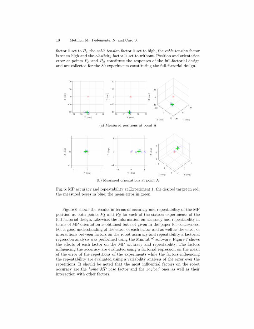
As per the exteroceptive measurements, the pose error is obtained as the differ-ence between the desired pose and the measured pose of the MP. For a givenexperiment, the error is evaluated for each of the five repetitions at the two targetpositions PA and PB . Figure 5 represents the MP pose error in terms of positionand orientation error at PA for the first experiment configuration. Similarly, thesame information is obtained concerning the pose PB but is not depicted in thispaper for the sake of shortness. In this case the configuration is: home MP pose
10 Metillon M., Pedemonte, N. and Caro S.
factor is set to P1, the cable tension factor is set to high, the cable tension factoris set to high and the elasticity factor is set to without. Position and orientationerror at points PA and PB constitute the responses of the full-factorial designand are collected for the 80 experiments constituting the full-factorial design.
−20 −10 0 10 20−20
−10
0
10
20
X (mm)
Z(m
m)
−20 −10 0 10 20−20
−10
0
10
20
Y (mm)
Z(m
m)
−20
0
20 −20
0
20
−20
0
20
X (mm) Y (mm)
Z(m
m)
(a) Measured positions at point A
−1 0 1
−1
0
1
X (deg)
Z(deg)
−1 0 1
−1
0
1
Y (deg)
Z(deg)
−1
0
1 −1
0
1
−1
0
1
X (deg) Y (deg)
Z(deg)
(b) Measured orientations at point A
Fig. 5: MP accuracy and repeatability at Experiment 1: the desired target in red;the measured poses in blue; the mean error in green
Figure 6 shows the results in terms of accuracy and repeatability of the MPposition at both points PA and PB for each of the sixteen experiments of thefull factorial design. Likewise, the information on accuracy and repeatability interms of MP orientation is obtained but not given in the paper for conciseness.For a good understanding of the effect of each factor and as well as the effect ofinteractions between factors on the robot accuracy and repeatability a factorialregression analysis was performed using the Minitab® software. Figure 7 showsthe effects of each factor on the MP accuracy and repeatability. The factorsinfluencing the accuracy are evaluated using a factorial regression on the meanof the error of the repetitions of the experiments while the factors influencingthe repeatability are evaluated using a variability analysis of the error over therepetitions. It should be noted that the most influential factors on the robotaccuracy are the home MP pose factor and the payload ones as well as theirinteraction with other factors.

Accuracy, Repeatability and Long Term running of a CDPR 11
1 2 3 4 5 6 7 8 9 10 11 12 13 14 15 160
5
10
15
20
25
30
35
Experiment number
Positionprecision(m
m)
Point A
Point B
(a) Accuracy
1 2 3 4 5 6 7 8 9 10 11 12 13 14 15 160
1
2
3
4
5
Experiment number
Positionrepeatability(m
m)
Point A
Point B
(b) Repeatability
Fig. 6: Position accuracy and repeatability for each experiment
0 2 4 6 8 10 12 14
BCD
ABC
ACD
AB
B
BD
ABD
D
A
BC
AD
CD
AC
C
12.71
Effect
Term
(a) Position accuracy
0 0.2 0.4 0.6 0.8 1
ABDAB
BCDACDCDA
BDBCAC
ABCDABC
BC
ADD
0.989
Effect
Lenth’s PSE = 0.38483
Term
(b) Position repeatability
0 2 4 6 8 10
ABC
CD
BD
AB
D
BC
ABD
AC
AD
A
B
C
3.182
Effect
Term
(c) Orientation accuracy
0 0.1 0.2 0.3 0.4 0.5 0.6 0.7 0.8
ABDA
ACDAD
ABCDABCBCDBDABCDDBC
ACBC
0.7111
Effect
Lenth’s PSE = 0.27665
Term
(d) Orientation repeatability
Fig. 7: Pareto effects of factors on responses: A, B, C and D stand for payload,cable tension, home MP pose and elasticity, respectively.
12 Metillon M., Pedemonte, N. and Caro S.
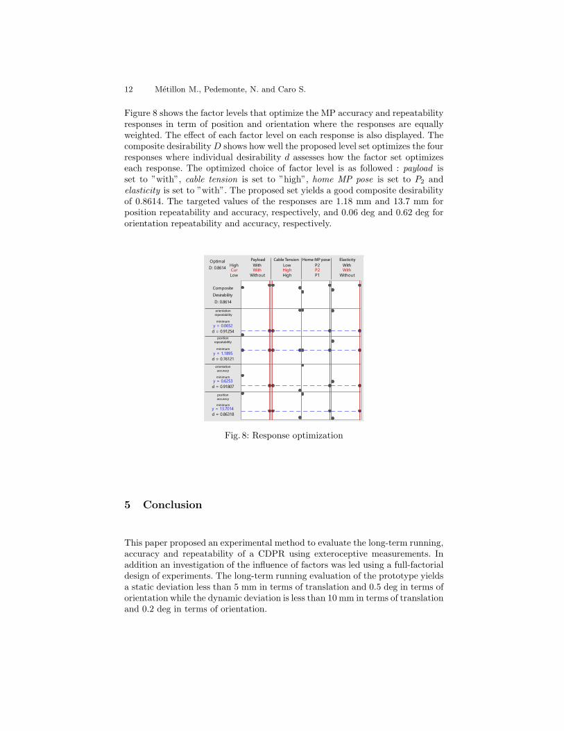
Figure 8 shows the factor levels that optimize the MP accuracy and repeatabilityresponses in term of position and orientation where the responses are equallyweighted. The effect of each factor level on each response is also displayed. Thecomposite desirabilityD shows how well the proposed level set optimizes the fourresponses where individual desirability d assesses how the factor set optimizeseach response. The optimized choice of factor level is as followed : payload isset to ”with”, cable tension is set to ”high”, home MP pose is set to P2 andelasticity is set to ”with”. The proposed set yields a good composite desirabilityof 0.8614. The targeted values of the responses are 1.18 mm and 13.7 mm forposition repeatability and accuracy, respectively, and 0.06 deg and 0.62 deg fororientation repeatability and accuracy, respectively.
CurHigh
Low
D: 0.8614
Optimal
d = 0.91254
y = 0.0652
orientation
repeatability
d = 0.76121
y = 1.1895
d = 0.91807
y = 0.6253
d = 0.86318
y = 13.7014
D: 0.8614
Desirability
Composite
Without
With
P1
P2
High
Low
Without
WithWith High P2 With
position
repeatability
orientation
accuracy
position
accuracy
minimum
minimum
minimum
minimum
ElasticityHome MP poseCable TensionPayload
Fig. 8: Response optimization
5 Conclusion
This paper proposed an experimental method to evaluate the long-term running,accuracy and repeatability of a CDPR using exteroceptive measurements. Inaddition an investigation of the influence of factors was led using a full-factorialdesign of experiments. The long-term running evaluation of the prototype yieldsa static deviation less than 5 mm in terms of translation and 0.5 deg in terms oforientation while the dynamic deviation is less than 10 mm in terms of translationand 0.2 deg in terms of orientation.

Accuracy, Repeatability and Long Term running of a CDPR 13
Acknowledgements
This research work is part of the PACE project managed by IRT Jules Verne(French Institute in Research and Technology in Advanced Manufacturing Tech-nologies for Composite, Metallic and Hybrid Structures). The authors wish toassociate the industrial and academic partners of this project, namely, NavalGroup, University of Nantes, IMT-Atlantique and CNRS. Tanguy Moro fromIRT JV and the anonymous reviewers are dutifully acknowledged for their greathelp in using Minitab® software and improving the paper, respectively. Thiswork is also supported by the ANR CRAFT project, grant ANR-18-CE10-0004https://anr.fr/Project-ANR-18-CE10-0004
References
1. Aflakian, A., Safaryazdi, A., Tale Masouleh, M., Kalhor, A.: Experi-mental study on the kinematic control of a cable suspended paral-lel robot for object tracking purpose. Mechatronics 50, 160–176 (2018).https://doi.org/10.1016/j.mechatronics.2018.02.005
2. Baklouti, S., Caro, S., Courteille, E.: Elasto-dynamic model-based con-trol of non-redundant cable-driven parallel robots. In: Arakelian, V.,Wenger, P. (eds.) ROMANSY 22: robot design, dynamics and control,CISM courses and lectures, vol. 584, pp. 238–246. Springer, Cham (2019).https://doi.org/10.1007/978-3-319-78963-7 31
3. Bayani, H., Masouleh, M.T., Kalhor, A.: An experimental study onthe vision-based control and identification of planar cable-driven par-allel robots. Robotics and Autonomous Systems 75, 187–202 (2016).https://doi.org/10.1016/j.robot.2015.10.002
4. Dallej, T., Gouttefarde, M., Andreff, N., Michelin, M., Martinet, P.: Towardsvision-based control of cable-driven parallel robots. In: 2011 IEEE/RSJ Interna-tional Conference on Intelligent Robots and Systems. pp. 2855–2860. IEEE, Pis-cataway (Sept 2011). https://doi.org/10.1109/IROS.2011.6094591
5. Fortin-Cote, A., Cardou, P., Campeau-Lecours, A.: Improving cable driven parallelrobot accuracy through angular position sensors. In: Staff, I. (ed.) 2016 IEEE RSJInternational Conference on Intelligent Robots and Systems (IROS). pp. 4350–4355. IEEE, Piscataway (Oct 2016). https://doi.org/10.1109/IROS.2016.7759640
6. Garant, X., Campeau-Lecours, A., Cardou, P., Gosselin, C.: Improving the forwardkinematics of cable-driven parallel robots through cable angle sensors. In: Gosselin,C., Cardou, P., Bruckmann, T., Pott, A. (eds.) Cable-driven parallel robots, Mech-anisms and Machine Science, vol. 53, pp. 167–179. Springer Berlin Heidelberg, NewYork NY (2017). https://doi.org/10.1007/978-3-319-61431-1 15
7. Gosselin, C., Foucault, S.: Experimental determination of the accuracy ofa three-dof cable-suspended parallel robot performing dynamic trajectories.In: Pott, A., Bruckmann, T. (eds.) Cable-Driven Parallel Robots, Mecha-nisms and Machine Science, vol. 32, pp. 101–112. Springer, Cham (2015).https://doi.org/10.1007/978-3-319-09489-2 8
8. Korayem, M.H., Tourajizadeh, H., Taherifar, M., Khayatzadeh, S., Maddah, M.,Imanian, A., Tajik, A.: A novel method for recording the position and orientationof the end effector of a spatial cable-suspended robot and using for closed-loop

14 Metillon M., Pedemonte, N. and Caro S.
control. The International Journal of Advanced Manufacturing Technology 72(5-8), 739–755 (2014). https://doi.org/10.1007/s00170-014-5681-2
9. Korayem, M.H., Yousefzadeh, M., Kian, S.: Precise end-effector poseestimation in spatial cable-driven parallel robots with elastic ca-bles using a data fusion method. Measurement 130, 177–190 (2018).https://doi.org/10.1016/j.measurement.2018.08.009
10. Merlet, J.P.: Direct kinematics of cdpr with extra cable orientation sensors: The 2and 3 cables case with perfect measurement and sagging cables. In: 2017 IEEE/RSJInternational Conference on Intelligent Robots and Systems (IROS). pp. 6973–6978(2017). https://doi.org/10.1109/IROS.2017.8206622
11. Merlet, J.P., Papegay, Y., Gasc, A.V.: The prince’s tears, a large cable-drivenparallel robot for an artistic exhibition. In: 2020 IEEE International Conferenceon Robotics and Automation (ICRA). pp. 10378–10383. [IEEE], [Piscataway, NewJersey] (2020). https://doi.org/10.1109/ICRA40945.2020.9197011
12. Oftadeh, R., Aref, M.M., Taghirad, H.D.: Forward kinematic analysis of a planarcable driven redundant parallel manipulator using force sensors. In: IntelligentRobots and Systems (IROS), 2010 IEEE/RSJ International Conference on. pp.2295–2300. IEEE (2010). https://doi.org/10.1109/IROS.2010.5649471
13. Picard, E., Caro, S., Claveau, F., Plestan, F.: Pulleys and force sensors influence onpayload estimation of cable-driven parallel robots. In: IROS 2018. pp. 1429–1436(2018). https://doi.org/10.1109/IROS.2018.8594171
14. Picard, E., Caro, S., Plestan, F., Claveau, F.: Stiffness oriented tension dis-tribution algorithm for cable-driven parallel robots. In: Lenarcic, J., Sicil-iano, B. (eds.) ADVANCES IN ROBOT KINEMATICS 2020, Springer Pro-ceedings in Advanced Robotics, vol. 15, pp. 209–217. Springer, [S.l.] (2020).https://doi.org/10.1007/978-3-030-50975-0 26
15. Pott, A., Tempel, P., Verl, A., Wulle, F.: Design, implementation and long-term running experiences of the cable-driven parallel robot caro printer.In: Pott, A., Bruckmann, T. (eds.) Cable-Driven Parallel Robots, Mecha-nisms and Machine Science, vol. 74, pp. 379–390. Springer, Cham (2019).https://doi.org/10.1007/978-3-030-20751-9 32
16. Scalera, L., Gallina, P., Seriani, S., Gasparetto, A.: Cable-based robotic crane(cbrc): Design and implementation of overhead traveling cranes based on vari-able radius drums. IEEE Transactions on Robotics 34(2), 474–485 (2018).https://doi.org/10.1109/TRO.2018.2791593
17. Schmidt, V., Pott, A.: Increase of position accuracy for cable-driven parallel robotsusing a model for elongation of plastic fiber ropes. In: Wenger, P., Flores, P.(eds.) New trends in mechanism and machine science, Mechanisms and MachineScience, vol. 43, pp. 335–343. Springer Berlin Heidelberg, New York NY (2016).https://doi.org/10.1007/978-3-319-44156-6 34
18. Schulz, S., Seibel, A., Schlattmann, J.: Performance of an imu-based sensor conceptfor solving the direct kinematics problem of the stewart-gough platform. In: IROS2018. pp. 5055–5062 (2018). https://doi.org/10.1109/IROS.2018.8594039
19. Siciliano, B., Khatib, O. (eds.): Springer Handbook of Robotics. Springer Hand-books, Springer International Publishing, Cham, 2nd edition edn. (2016)
20. Zake, Z., Chaumette, F., Pedemonte, N., Caro, S.: Robust 2½d visualservoing of a cable-driven parallel robot thanks to trajectory track-ing. IEEE Robotics and Automation Letters 5(2), 660–667 (2020).https://doi.org/10.1109/LRA.2020.2965033