evaluation of a tensile test for the … of a tensile test for the determina tion of the ma terial...
TRANSCRIPT
AUTEX Research Journal, Vol. 10, No4, December 2010 © AUTEX
http://www.autexrj.org/No4-2010/ 88
EVALUATION OF A TENSILE TEST FOR THE DETERMINATION OF THE MATERIALBEHAVIOUR OF FILAMENT YARNS UNDER HIGH STRAIN RATES
Chokri Cherif, André Seidel, Ayham Younes, Jan Hausding
Institute of Textile Machinery and High Performance Material Technology (ITM),Technische Universität Dresden, 01062 Dresden, Germany
Tel: +49 351 463 39300; fax: +49 351 463 39301, E-mail address: [email protected]
Abstract:
In many technical applications, fibre-reinforced composites with textile high-performance fibres made of carbonor glass are being used. The fibres qualify for their high strength and stiffness due to their physical and chemicalcharacteristics. It is necessary to guarantee a high safety level under all possible loading constellations. Besidesthe usual service loads, the topic of extreme loads that work along with high forces and high impact velocity is ofincreasing importance. For these so-called impact loads, the processes within the structural components haveto be analysed and material models suitable for prognoses should be derived from them. The existence ofsuitable test machines and test methods is a prerequisite for that, yet for filament yarns they are not state of theart. Hence, tensile tests with high strain rates on filament yarns are performed on standard high-speed tensiletesting machines. This leads to problems when analysing and interpreting the results and therefore, it is necessaryto develop special testing machines for filament yarns.
Key words:
Fibre reinforced concrete, impact load, high impact velocity, high strain rates, high speed tensile tests, highperformance yarns
Introduction
In the field of composite material, the topic of impact loads hasbeen gaining more and more importance due to increasinglycomplex constructions and the constantly increasing safetydemands. One current topic is energy-intensive loads thatoccur suddenly and only temporarily, as in impact orexplosions. In this context, high tensile forces develop in thetextile reinforcements which are embedded in the compositeduring impact times of micro- or milliseconds. Accordingly, thetextiles have to absorb high strain rates and therefore need ahigh energy absorption potential when deformed. In this casethe material behaviour does not correspond to the knownbehaviour under static and quasi static loads. The developmentof suitable calculation and measuring models under suchimpact loads demands a detailed analysis of the processesoccuring in the material and an exact knowledge about thefailure mechanisms of the textile structures responsible forthe transfer of the tensile forces.
The focus of the present study is the evaluation of the currentlyavailable test stands and measuring methods which helpresearch the stress-strain behaviour of multifilament yarnsunder high strain rates.
Initial situation and aim
The subject of the material behaviour of textile fabrics underhigh strain rates plays an important role when focussing onmain points such as impact-exposed applications in the fieldof fibre-reinforced polymers. Many researches already existwhich deal with the topic of the behaviour of composite materialwith regard to the modelling of the damage and the prognosisof the remaining load-bearing capacity. Especially in the fieldof vehicle construction and aerospace technology, impactprocesses are significant for the evaluation of crash behaviour[3, 12]. Another application field is the use of high-performancetextiles in bullet-proof vests and helmets which are especially
designed for impact loads [2, 15]. Researches concerned withthat show that the deformation and failure behaviour of textilefibre-reinforced structures under high load rates can only bepresented realistically when enough knowledge is presentabout the load condition occuring in the process and the energyabsorption potential of all materials in the compound. Moreover,possible delamination effects between the textile fibres andthe surrounding matrix need to be considered.
Buildings and other massive constructions can be exposed tolocal impact loads when under extreme external impacts. Withrespect to that, former researches mainly analyse thebehaviour of the concrete or the brickwork under impact-relatedinfluences [19, 20]. Building upon that, a modelling of thesupporting structure under highly dynamic loads can berealized with the help of the finite element method [8, 25].
A rather new technology is the application of textile structuresas a reinforcement in concrete components either as analternative to the standard steel reinforcement or in the courseof the renovation and reinforcement of existing constructions.In this field, extensive research has been carried out and bynow, sufficient knowledge about the behaviour under mainlyconstant loads is available [4, 7, 10].
With an increasing application as well as a look into possibleextreme impact effects such as explosion or aircraft crash onthe buildings, the necessity for the evaluation of impactbehaviour is being given more priority. Already for a long time,Ultra High Performance Concrete (UHPC) with very highcompressive strength has been worked on, which issuccessfully used in the security-related areas of massivebuildings (e.g. nuclear reactors) [27]. To improve the tensilestrength and to restrict cracking, textile fibres are added, yet atthe moment preferably short fibres. With this, a significantlymore ductile material behaviour can be realized and therefore,possible damage can be reduced.
0356.pdf

AUTEX Research Journal, Vol. 10, No4, December 2010 © AUTEX
http://www.autexrj.org/No4-2010/ 89
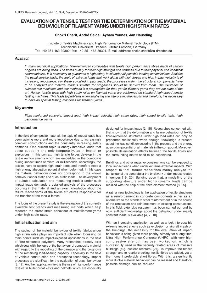
Figure 1. test machines for high load rates (source: Zwick, Ulm):a) servo-hydraulic high performance testing machine for test speedsof up to 20 m/s,b) drop impact testing machine, test speeds up to 10 m/s from amaximum of 5 m height of free fall,
c) pendulum impact testing machine, test speeds of up to 3 m/s.
The description and the modelling of the processes takingplace under impact load in components or buildings requireextensive knowledge about the strain-rate dependent strength,not only for the composite material as a whole but especiallyalso for the applied textile structures. For this, tests are usedin which the yarn is rapidly broken with extremely high loadingrates. The testing methods applied for this problem rangefrom high speed testing machines via rotation test stands,drop- and pendulum impact testing machines to test standspowered by explosions, see examples in Figure 1. In all cases,the stress-strain behaviour of the tested specimen has to berecorded as precisely as possible within an extremely shorttest duration of usually less than one millisecond which,therefore, demands high frequency measuring methods. Twoof the leading providers of such test machines are thecompanies Zwick GmbH & Co. KG (Ulm, Germany) and Instron(Norwood, USA). Furthermore, a variety of special testmachines exist for special measurements in research facilitiesand companies. However, there are no standardized andestablished testing methods or machines for short-termdynamic tensile test of textile multifilament yarns. Therefore,the testing machines developed mainly for metallic testspecimens need to be evaluated and adapted for theirsuitability. In a second step, suitable methods for the precisemeasurement of the load-time curve and the path-time curveneed to be developed and applied.
Research status
Former research on impact-loaded high-performance fibresare primarily connected to the applications in fibre-reinforcedpolymers: the analysis of filament yarns alone is rare. Thiscan be ascribed to the fact that the research of the strainbehaviour of high performance filament yarns with a sufficientlyhigh measurement accuracy is only possible when performedand evaluated carefully even under quasi-static load.Significant problems can be found in the clamping techniqueand in the determination of the length change. Test machinesoptimized to answer such questions are not available toeverybody. Basically, it can be stated that the according materialcharacteristics are not derivable from the common knowledgeunder quasi static load. Available literature about the testing ofreinforced and non-reinforced synthetic materials allowsconclusions on the testing method and the behaviour of the
test machine during the test besides the evaluation of thematerial properties.
Research for the determination of the parameters which aredependent on the strain rate, such as failure, as well as thedamage behaviour of composite components made of glassfibre multi-layer weft knits (GF-MLG) show that increasing strainrates correlate to the increase of tensile strength, strain andstiffness [11]. A servohydraulic high performance test unit byInstron was used for the test in combination with a laser dopplerextensometer and a high speed camera. The test probes wereanalysed under strain rates of up to 40 s-1. With an increasingloading rate, oscillations occur that result from the stimulationof the natural frequency of the entire test system and whichoverlay the measuring results.
Similar results could be achieved for short glass-fibrereinforced polyolefins with a servohydraulic test machine VHS25/25-20 by Instron. With a test length of 115 mm, strain ratesof up to 174 s-1 could be reached. A positive strain-rate relatedbehaviour was found for the analysed material. When strainrates are higher, the stiffness increases while the straindecreases at the same time. When the strain rate is higherthan 20 s-1, this effect is much more pronounced which canbe referred to the transition from isothermic to adiabaticbehaviour. This measurement process also possessesobvious oscillations of the measuring system with increasingstrain rates. A clear increase of the tensile strength with carbonfibre-reinforced polymer can be observed with an increasingstrain rate [9]. Yet, a direct connection between Young‘smodulus and the strain rate could not be found in the probestested. The behaviour of polymers under highly dynamic loadshas also been analysed in numerous research papers. Itresembles that of fibre composites and shows a higher tensilestrength while the strain decreases at the same time whenstrain rates increase [6, 17, 29].
Further research deals with the material behaviour ofcomposites with respect to the modelling and the prognosisof the remaining load-bearing capacity after impact [13]. Here,the results show that the deformation and failure behaviour offibre-reinforced composites under highly dynamic load canonly be realistically understood if there is sufficient knowledgeabout the process taking place in the material [3]. To determineand model material properties dependent on strain rates,there are first basic approaches [2, 23]. For example, amodified G’Sell-Jonas-Modell for the calculation of materialcharacteristic values with high strain rates was applied in [23].The according strains with a maximum tension from the quasistatic tensile test were used as initial points. With that, it ispossible to describe the strength properties which aredependent on the strain rates. For test speeds of more than20 m/s, test methods are currently not available, and the existingtests are not suitable, without any adjustment, for the analysisof high-performance fibres. Moreover, material models for suchhigh load speeds do not exist.
With regard to the application of metallic or polymerreinforcements for concrete components, there is not yetsufficient knowledge about the behaviour of fibre materialsunder impact load. The research that has been performed inthis field so far mainly deals with the behaviour of pure concreteunder highly dynamic load. Thus, it has been known for a longerperiod of time from the technical literature that the increase ofthe strain rate leads to an increase of the tensile strength [1, 5,16, 18, 21, 22, 28]. Also, the effect of fibre reinforcementincreasing in stiffness leads to a restriction of crack formation
0356.pdf

AUTEX Research Journal, Vol. 10, No4, December 2010 © AUTEX
http://www.autexrj.org/No4-2010/ 90
and to a ductile material behaviour, as proved in numeroustests [26]. First research on the behaviour of 2D or 3D textilereinforcements for concrete components under explosion loadshows an evenly improved behaviour compared to standardsteel reinforcements [14]. In studies of sisal-reinforced concretetest bodies, the positive effect of the textile reinforcements underimpact load in the form of wider crack openings could be proved[24].
High speed tensile tests on filament yarns
Based on extensive experience in the field of textile testingunder static and quasi static loads, first own tensile tests wereperformed with the yarns listed in Table 1 on the servohydraulichigh speed testing machine presented in Figure 1a. Theoperating principle of this test machine by Zwick isrepresentative for the currently used industry standard. Theobject of these tests was the development and testing ofsuitable sample holders as well as the identification andjudgement of significant issues for force and distancemeasuring. First knowledge about the stress-straincharacteristics of multifilament yarns loaded dynamically in avery short time period was gained and significant parametersfor the measured values to be specified were worked out. Withthis, an important foundation was laid for the approach infur[M1]ther research activities.
Table 1. Test program for tension tests under high strain rates.
Test set-up and performance
The aim of the high speed tension tests on textile yarns is toresearch failure mechanisms at very high strain rates widelyunknown up to today. Here, the relative change in length withina (very short) time frame is observed and therefore, the shortestpossible length of the test body in the test set-up should bestriven for. In Figure 3, the dependence of the strain rate on thelength of the test body is presented, [M2]as can be expectedfor small strain rates from the knowledge about static andquasi static conditions. With this, an inversely proportionalcontext exists which means doubling the length of the testbody results in half the strain rate and the latter decreasesana[M3]logically to the test speed starting at the load feedingpoint to the clamping end of the test body linear down to zero.In the middle of the test body, the strain rate m is therefore halfof the maximum strain rate max at the load feeding point.
Figure 2 shows a test on a carbon filament yarn. The massiveconnection points in the test machine, which are designedprincipally for metallic test bodies and much higher tensions,can be seen very clearly. The high speed camera in thebackground records both changes in path length as well asthe the breaking process of the yarn probe during the tensiontest, which lasts only fractions of a millisecond.
Figure 2. High speed tension test on a carbon filament yarn 800 tex
with a testing speed of 20 m/s (left: before the test; right: after the test)
Figure 3. Connection between test body length, test speed and strain
rate.
The smallest test body length possible between the clampingdevices is mainly determined by the given conditions in thetest machine and the necessary space requirement formeasuring the change in length during the test. There werefree test lengths of about 10 to 15 cm in the tension testsperformed on textile high performance fibre yarns and with theavailable technical equipment. In Figure 4a one can see theclamping device for the test screening that was used in thefirst tests, which had been developed for that purpose. It allowsa slip- and damage-free clamping of the multifilament yarnsunder those high strain rates. Their ad[M4]aption within thetest machine is schematically presented in Figure 4b.
Figure 4. Clamping of the textile yarn probes in the high speed tensiontesting machine:a) Test holder developed for the clamping of multifilament yarns,
b) Schematic sketch.
One focal point of tension tests performed with this test set-upis the study of carbon filament yarns with a yarn count of 800tex, as used in many technical applications. For those, thecharacteristics presented in Table 2 can be applied with amaximum possible test speed of 20 m/s. However, an exactdetermination is not possible with the currently availabletechnical equipment.
0356.pdf
Tested yarns Yarn count Test speed
Carbon filament yarn, uncoated
800 tex 1 m/s, 2 m/s, 5 m/s, 10 m/s, 15
m/s, 20 m/s
AR-glass filament yarn, uncoated
640 tex 20 m/s
Aramid yarn 336 tex 20 m/s
Polyethylen (Dyneema) 175 tex 20 m/s
Steel filament yarn 500 tex 20 m/s
Steel wire Ø 0,6 mm complies with
2220 tex 20 m/s

AUTEX Research Journal, Vol. 10, No4, December 2010 © AUTEX
http://www.autexrj.org/No4-2010/ 91
Collection of data during the tension test
The test period which is listed among the conditions in Table2 and which means the time frame between the impact of theload and the actual breaking is theoretically only 0.05 ms. Duringthis time period, the yarn tension and the change of the lengthhave to be determined. This demands the use of highfrequ[M5]ency measuring methods to be able to collect enoughmeasuring values for meaningful results. Based on this, thestress-strain characteristic of each yarn can be determinedfrom the entering force until the breaking and the resultinglength increase after the nomination on the cross-section andthe initial length. Since load and path are usually measuredseparately, both signals have to be synchronized.
In the following, the methods used in the first pretests for theload and path measurement will be described, the resultsintroduced, their limitations presented, and requirements forfuture works established.
Realization of the load measurement
For the determination of the yarn tension with the high speedtest machine presented in Figure 1b, a load cell integrated inthe test machine is used in the pretests. This cell is built intothe bottom part of the testing machine, which means in thefixed clamping end, and it is used for the measurement offorces of up to 50 kN. The load cell is based on the Piezotechnology and has a weight of about 250 g and a naturalfrequency of about 10 kHz according to the manufacturer’sinformation. As long as measuring and sampling frequenciesare clearly below that natural frequency, precise statementscan be given about the applied forces.
The load cell was triggered with a sampling frequency of 125kHz during the performed tests. With this, 6 measuring valuescan be collected in the theoretical measuring period of 0.05ms. Since this sampling frequency is clearly above the naturalfrequency, a measurement of the yarn tension is not possible.The values presented by the load cell instead show anoscillation course which is caused by the spring dampersystem created by the load cell with both overall masses andthe subsequent test clamping and the resulting naturalfrequency at the moment of the impact of the load impulse.Two of the typical processes for such load measurements arepresented in Figure 5 for different test bodies.
As can clearly be seen, this method is not adequate fordetermining yarn tensions under the required test speeds.The application’s limitation are, in this case, to measuringfrequencies of 6 to 7 kHz, which means the release ofmeasured values is about 0.15 ms. Test speeds of up to 1 m/s can be covered quite reliably with the tested carbon filamentyarns having the marginal conditions presented in Table 2. Inthe course of future research, load measuring devices withclearly higher natural frequencies need to be developed forthe determination of load-time courses with higher speeds. Asignificant aspect in this is the mass of the entire system madeof the load transducer and the connected clamping device.These components work together according to the principle ofa spring damper system and they are subject to more or lessheavily distinct self-oscillations according to their mass andstiffness distribution when stimulated by a load impulse(impact of the load). Hence, they need to be constructed with alow mass and a high stiffness at the same time for themeasurements to be performed.
Table 2. Theoretical characteristics of the high speed tension testsfor carbon filament yarns 800 tex at a traverse speed in the testmachine of 20 m/s.
Carbon tensile tests – selected characteristics and technical specifications
Test body / Roving Carbon filament
yarn 800 tex
Cross-section of the roving AR = 0.447 mm²
Length of the test body between the test holders L0 = 120 mm
Speed of the load feeding vo = 20 m/s
Breaking strength FBr = ~ 1 kN
Increase of length till failure ∆lo = ~ 1 mm
Breaking strain Br = ~ 8 ‰
Test period until breaking tBr = 0.05 ms
Maximum strain rate at the top clamping end max = 160 s-1
Average strain rate in the middle of the test body m = 80 s-1
Figure 5. Presentation of exemplary load-time courses of the load cellinternal to the test machine with a sampling frequency of 125 kHz anda rated test speed of 20 m/s:a) carbon filament yarn 800 tex,
b) polyethylen Dyneema 175 tex.
Realization of the displacement measurement
A high speed image acquisition system consisting of a highspeed camera and the evaluation software is used for thedisplacement measurement. The basic set-up andfunctionality are presented in Figure 6. The photographicrecording of the test body with two applied measuring marksis done with a recording frequency of 125 kHz. Withoptoelectronic methods, the path-time courses can bedetermined in the first step and after the differentiation, thelength increase of the test body can be determined in the
0356.pdf

AUTEX Research Journal, Vol. 10, No4, December 2010 © AUTEX
http://www.autexrj.org/No4-2010/ 92
second step. The evaluation provides the overall value of theyarn strain as a function over time based on the initial length.Furthermore, the used system allows the observation of anynumber of measuring values with the help of the test bodylength. With this, it will be possible in further research to notonly determine the overall strain but also to make statementsabout the course of the strains using the yarn length.
Results and evaluation
The performed high speed tension tests allow first conclusionsabout the deformation behaviour of the tested yarns under theapplied test conditions. For this, the path-time coursesrecorded with the high speed image acquisition system areb[M6]eing analysed more closely. The measuring point fixedon the top end of the yarn represents the deformation courseof the stretched yarn as well as the movement of the top yarnholding and therefore, the movement of the securely fastened(in the sense of infinitely stiff) piston rod in the test machine.After the derivation of the time, the approximate speed can bedetermined at the measuring point from the path-time curve.This is presented in the following using an exemplary test of acarbon filament yarn 800 tex. Figure 7a shows their path ofmotion which means the path of motion of the end test set-upin the test machine which is to be accelerated. As can clearlybe seen, the curve starts with a very flat increase which becomessteeper in the course of the experiment. In Figure 7b, the courseof the speed gradient determined from this data is shown.This is also not linear and there is a continuous increase ofspeed up to the peak of, in this case, 20 m/s.
The evaluation of the motion sequence shows that under themarginal conditions of the used test machine, the test body isnot struck with the rated test speed of 20 m/s but that thespeed starting at zero continuously increases. This can beexplained by the technology of the test machine, since thepiston rod impacting the accelerating probe end has to beaccelerated itself from zero to the demanded speed. This takesplace in a time interval of ∆t ≈ 0.24 ms in a non-linear courseand with a covered distance of ∆l ≈ 1.2 mm. The breakingelongation is at about 1 mm (see Table 2) for the tested carbonspecimen with a length of about 120 mm. This means that thespecimen has already broken when the test machine reachesits maximum speed. In the case presented, speeds of about14 to 15 m/s were calculated at the test specimen the momentit broke. The actual test period from the striking of the load untilbreaking is about 0.2 ms.
Important conclusions which can be dealt with in futureresearch can be drawn from the described observations of theperformed tests. Those significant aspects are summarizedin the following.
Acceleration process in the testing machine
The used high speed testing machine Zwick HTM works on aservohydraulic base in whose work cylinder a piston isaccelerated to the target speed. This can happen in bothdirections which means for both pressure and tension tests. Acarrier is closely connected to the piston which provides thenecessary start-up length for the acceleration to the targetspeed. At the end of the start-up length, the carrier connects toanother piston on which the load feeding into the top clampingend of the test body occurs. The contact area between thecarrier and the piston rod is disguised with elastic material tominimize wearout. With this - as well as due to the inertia of thepiston rod itself - a finite time period ∆t and an associated path∆l is always necessary until the piston rod has reached thespeed of the carrier as well. The acceleration processhappening thereby is dependent on the mass and stiffnessrelations of all participating components and can only be partlyinfluenced when a standard test machine is used. A closeranalysis of the processes taking place in the test machine atthe moment of the acceleration process is therefore necessaryfor the evaluation of the test results.
Load feeding speed at the impact on the test specimen
When the testing machine equipment and a secure connectionwith the top clamping end of the specimen is used, a loadfeeding with the rated speed can inevitably not take place, butthe identical acceleration process described above isperformed here. To reach an impact of the load on the specimenwith a maximum speed, a further start-up length was necessarybetween the piston rod of the test machine and the topspecimen holder that has to cover their speed path ∆l (about 1to 2 mm). The following requirements should be made for thetransmission of the load impulse in the test body:
• Acceleration of the specimen holder from zero to target speed
→ ∝,
• Mass of the specimen holder (if necessary including force
measuring element) → 0,
• Stiffness of the specimen holder → ∝.
Since there are physical limitations to the requirementsdescribed above, the achievable speeds in the test body will
Figure 6. Basic set-up and functionality of a high speed image acquisition system (high speed camera and evaluation of system ARAMIS / GOM).
0356.pdf

AUTEX Research Journal, Vol. 10, No4, December 2010 © AUTEX
http://www.autexrj.org/No4-2010/ 93
always be dependent on the chosen test set-up. It is a maintask for further research to optimize this set-up.
Realization of the load and displacement measurement
As all performed tensile tests have clearly shown, it is basicallynot possible to determine the forces in the test body for speedsof more than 1 m/s with the test machine’s internal Piezo-carrier due to its relatively low natural frequency. The applicationof a load measuring element with a significantly lower massand higher stiffness whose natural frequency has to be clearlyabove the necessary measuring frequency is required for highfrequency force measurements. For this, Piezo-carriers withthe corresponding technical characteristics are preferable.Alternatively, an indirect load measurement using straingauges which are fixed on a carrier integrated in the clampingdevice is also possible as long as it has a sufficiently highnatural frequency.
Besides the problem of the force measurement, there is asecond challenge in the performance of the high frequencypath measurement. Here, first tests have shown that a veryprecise determination of the motion processes of themeasuring marks fixed on the test body is possible withoptoelectronic methods when a high speed camera is used.The evaluation of these motion processes will not only providedetailed information on the absolute length change but alsoon the strain course with the help of the yarn length. Thistechnology will therefore have to be analysed further in futureresearch.
Conclusion
With the tests performed, it was possible to gain first importantknowledge for future tension tests of textile yarns under highload rates. Significant aspects of the test set-up as well as thenecessary measuring methods for the determination of theload-time course and the path-time course within a very shorttest period could be identified. Numerous changes have to bedone on textile test bodies for tensile tests of yarns as isforeseeable from the collected experiences on the high speedtest machine of the company Zwick. This mainly includes theclamping of the yarns, the problem of the transmission chainof the load impulse starting at the servohydraulic workingcylinder via the start-up length and the contact to the followingpiston rod and to the test body as well as the adjustment of thecarrier to meet the demands regarding measurements undervery high load rates.
Especially the problem of force measurement under high testspeeds in combination with a suitable test stand will be thefocus of future research. The main task here is the realizationand optimization of a test stand that reaches a high resonancefrequency of the entire force measuring device even with aminimized weight and very high stiffness of the movedcomponents. Only so can oscillation influences can be reducedand enough meaningful measured values be recorded in theextremely short test time of clearly under one millisecond.
Furthermore, it could be noticed during the performed teststhat the semi-elastic damping during the power transfer fromthe test machine to the test body with the help of an acceleratingpiston causes a long delay in the target speed’s being reached.Hence, technologies need to be developed that help the loadinitiating device coming from the test stand to push the testbody to reach the target speed within the shortest time possible.To keep the forces which would accompany this as low aspossible, the constructional details such as the clamping ofthe test body and the integration of the force measuring deviceshave to be optimized further. Falling weight test stands as wellas centrifugal ones, for example, are suitable for the realizationof these requirements, in which a carrier transfers the forceimpulse striking the test body almost without delay and with aconstant target speed as well as a high mechanical energy.These aspects are the focal points of our current and futureresearch.
Regarding the deformation measurement, good results havebeen achieved so far using high-speed image acquisitionsystems. However, experience has shown that the technologyof optoelectronic evaluation on filament yarns is very difficult touse since those yarns do not provide connected, self-containedareas along the length of the test body. For a qualitatively reliableand reproducible evaluation of the measured deformations, afurther need for research and optimization exists here as well.This enquiry into the research status of the field of materialtesting under impact load has shown that due to the stringentdemands of yarn testing, test stands solely and especiallyconstructed for that purpose are often employed. In currentworks, the possibilities of special test set-ups with integratedload and path measurement methods are examined and firstprototypes are practically implemented in the frame of pretestsbased on the defined requirements on the tensile test of textilehigh performance fibre yarns. The force measurement isperformed on both the fixed and the accelerating clampingend.
Figure 7. Presentation of an exemplary motion course of the measuringpoint fixed upon the sped up end for a carbon filament yarn 800 tex(complies with the motion sequence of the piston rod in the testmachine):a) presentation of all measured path-time courses,b) presentation of the calculated speed-time course.
0356.pdf

AUTEX Research Journal, Vol. 10, No4, December 2010 © AUTEX
http://www.autexrj.org/No4-2010/ 94
In conclusion, it can be determined that the main task ofresearch dealing with the load-deformation behaviour underimpact loads consists to a substantial degree of the control ofthe measuring methods for force and path within the extremelyshort test period. This is valid for textile yarns and also for allother materials under this load scenario.
Acknowledgment
The authors gratefully acknowledge the technical support ofthis research by Zwick GmbH & Co. KG (Ulm, Germany) andGOM GmbH (Braunschweig, Germany).
References:
1. BIRKIMER, D. L.; LINDEMANN, R.: Dynamic Tensile Testof Concrete Materials. In: ACI Journal, Vol. 68, 1971, pp.47-49.
2. BLANKENHORN, G.; SCHWEIZERHOF, K.; FINKH, H.:Improved Numerical Investigations of a Projectile Impacton a Textile Structure. 4th Europ. LS-DYNA Conference,Ulm, Germany, 22.-23.05.2003, pp. G-I-07-G-I-14.
3. BOROVKOV, A.; KLYAVIN, O.; MICHAILOV, A.;KEMPPINEN, M.; KAJATSALO, M.: Finite Element Modelingand Analysis of Crash Safe Composite Lightning Columns,Contact-Impact Problem. 9th Int. LS-DYNA Conference,Dearborn, MI, USA, 04.-06.06.2006, pp. 18-41-18-51.
4. BRAMESHUBER, W.; RILEM TC 201-TRC: TextileReinforced Concrete. State-of-the-Art Report of RILEMTechnical Committee 201-TRC, 2006, BAGNEUX: RILEM,REPORT 36.
5. CADONI, E.; LABIBES, K.; ALBERTINI, C.: Strain-RateEffect on the Tensile Behaviour of Concrete at DifferentRelative Humidity Levels. In: Materials and Structures, Vol.34, 2001, pp. 21-26.
6. CHEN, W.; LU, F.; CHENG, M.: Tension and CompressionTests of Two Polymers under Quasistatic and DynamicLoading. In: Polymer Testing, Vol. 21, 2002, pp. 113-121.
7. CURBACH, M.; JESSE, F.: Textile Reinforced Structures:Proceedings of the 4nd Colloquium on Textile ReinforcedStructures (CTRS4), Dresden, 3.-5.6.2009. SFB 528,Technische Universität Dresden, D-01062 Dresden:Eigenverlag, 2009, - ISBN 978-3-86780-122-5.
8. DOORMAAL, J.; WEERHEIJM, J.; SLUYS, L.J.:Experimental and numerical determination of the dynamicfracture energy of concrete. Journal de Physique IV,Colloque CX, supplement au Journal de Physique III, Vol.4, septembre 1994, pp. 501-506.
9. FITOUSSI, J.; MERAGHNI F.; JENDLI, Z.; HUG G.;BAPTISTE D.: Experimental Methodology for High Strain-Rates Tensile Behaviour Analysis of Polymer MatrixComposites. In: Composites Science and Technology, Vol.65, 2005, pp. 2174-2188.
10. HEGER, J.; BRAMESHUBER, W.; WILL, N. (Edt.):Proceedings of the 1st International RILEM Conference.September 6-7, 2006, Aachen, Germany. RILEMPublications S.A.R.L., 2006.
11. HUFENBACH, W.; ANDRICH, M.; GUDE, M.; LANGKAMP,A.: Contribution to the Simulation of Textile ReinforcedPlastics under Crash and Impact Load. In: Kompozyty(Composites), Vol. 4, 2004-9.
12. HUFENBACH, W.: Praxisgerechte Simulationsmodelle zurvirtuellen Entwicklung neuartiger Textil-verbundwerkstoffefür Crash- und Impactanwendungen unterBerücksichtigung von Mikro-Meso-Makro-Interaktionen.Forschungsbericht TU Dresden, ILK, 2008.
13. HUFENBACH, W. et. al.: Multidisciplinary Damage Analysis
of Textile-Reinforced Composites for Impact and CrashApplications. In: The e-Journal of Nondestructive TestingBd. 11, Vol. 12, 2006.
14. KARLSTETTER, Ch.: Anwendungspotenziale von textilen3D-Strukturen in Betonbauteilen. In: Cluster- Treff amFraunhofer Institut für Bauphysik 3D-Textilstrukturen zurBewehrung. July, 2010, Holzkirchen.
15. LANGKAMP, A.; HUFENBACH, W.; BÖHM, R.: Auslegungcrash- und impactbeanspruchter Leicht-baustrukturen austextilverstärkten Verbundwerkstoffen mit Hilfephänomenologischer Schädi-gungsmodelle. 10. DresdnerLeichtbausymposium, 2006.
16. MALVAR, L. J.; ROSS, C. A.: Review of Strain-Rate Effectsfor Concrete in Tension. In: ACI Materials Journal, Vol. 95,1998, pp. 735-739.
17. NAIK, N. K.; YERNAMMA P.: Mechanical Behaviour ofAcrylic under High Strain Rate Tensile Loading. In: PolymerTesting, Vol. 27, 2008, pp. 504-512.
18. OH, B. H.: Behavior of Concrete under Dynamic TensileLoads. In: ACI Material Journal, Vol. 84, 1987, pp. 8-13.
19. RIEDEL, W.: Beton unter dynamischen Lasten. Meso- undmakromechanische Modelle und ihre Parameter.Dissertation, Ernst-Mach-Institut, Freiburg, Fraunhofer(Hrsg.), 2004.
20. ROMANI, M.: Mauerwerk unter Druckstoßbelastung -Tragverhalten und Berechnung mit Verstär-kung durchKohlefaserlamellen. Dissertation, Ernst-Mach-Institut,Freiburg, Fraunhofer (Hrsg.), 2008.
21. ROSSI, P.; TOUTLEMONDE, F.: Effect of Loading Rate onthe Tensile Behaviour of Concrete: Description of thePhysical Mechanisms. In: Materials and Structures, Vol.29, 1996, pp. 116-118.
22. ROSSI, P.; VAN MIER, J.G.M.; TOUTLEMONDE, F.; LEMAOU, F.; BOULAY, C.: Effect of Loading Rate on theStrength of Concrete Subjected to Uniaxial Tension. In:Materials and Structures, 27, 1994, pp. 260-264.
23. SCHOßIG, M.; BIERÖGEL, Ch.; GRELLMANN, W.;MECKLENBURG, T.: Mechanical Behavior of Glass-FiberReinforced Thermoplastic Materials under High StrainRates. In: Polymer Testing, Vol. 27, 2008, pp. 893-900.
24. SILVA, F.D.A. et. al.: High Speed Tensile Behavior of SisalFiber Cement Composites. In: Cement and ConcreteResearch, Vol. 35, 2005, pp. 11-18.
25. SUKONTASUKKULA, P.; MINDESS, S.; BANTHIA, N.:Properties of confined fibre-reinforced concrete underuniaxial compressive impact. Cement and ConcreteResearch, Vol. 35, 2005, pp. 11-18.
26. SUKONTASUKKULA, P. et. al.: Properties of confined fibre-reinforced concrete under uniaxial compressive impact.In: Cement and Concrete Research, Vol. 35, 2005, pp. 11-18.
27. THOMA, K.: Fraunhofer Symposium, Future Security. 3rdSecurity Research Conference Karlsruhe, 10.-11.09.2008.
28. XIAO, S.; LI, H.; LIN, G.: Dynamic Behaviour andConstitutive Model of Concrete at Different Strain Rates.In: Magazine of Concrete Research. Vol. 60, 2008, pp.271-278.
29. XINRAN X.: Dynamic Tensile Testing of Plastic Materials.In: Polymer Testing, Vol. 27, 2008, pp. 164-178.
∇∆∇∆∇∆∇∆∇∆
0356.pdf