evaluation of brick kiln performances using computational...
TRANSCRIPT

Evaluation of Brick Kiln Performances using
Computational Fluid Dynamics (CFD)
A thesis submitted in fulfillment of the requirements for the degree of
Master of Engineering
A H Tehzeeb
B.Sc. in Mechanical Engineering
School of Civil, Environmental and Chemical Engineering
College of Science, Engineering and Health
RMIT University
March 2013

i
DECLARATION
I certify that except where due acknowledgement has been made, the work is that of the
author alone; the work has not been submitted previously, in whole or in part to qualify for an
academic award; the content of the thesis is the result of work which has been carried out
since the official commencement date of the approved research program; any editorial work,
paid or unpaid, carried out by a third party is acknowledged; and, ethics procedures and
guidelines have been followed.
A H Tehzeeb
25 March 2013

ii
ACKNOWLEDGEMENTS
I would like to thank several people for helping me to conduct this research. I would like to
express my gratitude to Dr. Muhammed Bhuiyan, my senior supervisor, for his patient
guidance and providing me the opportunity to do the Master’s degree. I would like to thank
my second supervisor Dr. Nira Jayasuriya, for her knowledge and support.
I would also like to acknowledge the help of Ms Elizabeth McIntyre, Chief Executive Officer
of Think Brick for extending her support. Also I would like to thank Austral Bricks for
allowing me to visit one of their factories and providing some first-hand knowledge and data.
I would like to express my gratitude to Mr. Gilbert Habla, Managing Director of Habla
Zigzag Kiln to share some invaluable information with us. I would also like to thank Mr.
Partha Haldar for his cooperation.

iii
Abstract
Modern history of civilization is concurrent to the use of brick and its manufacturing. Brick
kiln is the most important component in the manufacturing of clay-burnt bricks. Poorly
operated brick kilns are considered as the major sources of greenhouse gas (GHG) emission
nowadays. Various types of brick kilns are in operation throughout the world. Tunnel kiln is
the most widely used technology in developed countries as it is highly automated. Other
technologies which are quite popular in developing countries are: Hoffman kiln, Vertical
Shaft kiln, Fixed Chimney kiln, Zigzag kiln, etc.
Computational Fluid Dynamics (CFD) software, ANSYS CFX is being applied to evaluate
performance of Tunnel kiln using natural gas as its fuel. The idea of a typical Tunnel kiln
layout geometry has been envisaged from local brick industries. The length, width and height
of the Tunnel kiln geometry are taken as 100 m × 3.24 m × 1.48 m. The length and width of
the brick stack is taken as 920 mm × 440 mm. With a gap of 400 mm and 100 mm between
two brick stacks longitudinally and laterally respectively, a total of 450 (6 × 75) stacks can be
accommodated inside the kiln at a time. Brick stack height including the kiln car height is
taken as 1.38 m. There is a clearance of 100 mm between the stack and the kiln roof. To
produce certain quality bricks/ceramics, a particular temperature distribution throughout the
kiln needs to be maintained. This temperature distribution with respect to the kiln length is
known as Tunnel kiln curve. To achieve the Tunnel kiln curve obtained from industry for
ordinary brick type, some design parameters need to be optimized for a given geometry.
Selection of these optimized design parameters are obtained through a series of trial and error
runs of the CFD model. The total length of the tunnel can be divided into pre-heating, firing
and cooling zones. Green bricks pass through the pre-heating, then firing and finally the
cooling zones, while fresh air flows in opposite direction of the brick stack move. It is to be
noted that brick industries are very reluctant to disclose any of those technical secrets related
to their brick kiln design. In this regard, this design is based on initial guesses of those
parameters and slowly come up with best performing scenario with respect to considered
Tunnel kiln curve.
To achieve the Tunnel kiln curve, the design parameters that need to be played around are gas
and air flow rates, flow directions, their inlet-outlet number, spacing and placements at
different locations of the kiln are considered very crucial. Other important parameters that are
varied include brick stack placement with respect to air and gas inlet-outlets, gaps between

iv
kiln roof and stacks and gaps between two consecutive stacks. To supply adequate air, a large
rectangular air inlet with an area of 0.8 m2 is placed at the roof of the exit end of the kiln. To
maintain the air temperature distribution as given in Tunnel kiln curve, one intermediate size
air outlet with an area of 0.4 m2 and a series of 13 rows × 12 columns small air inlet-outlets
(openings) are also placed at the roof of the kiln in the cooling zone. All these heated air has
been transferred to dryer to dry the green bricks. A series of 12 rows × 12 columns of gas
inlets are placed in the roof of the firing zone. At the entry end of the tunnel, a flue gas outlet
with an area of 0.8 m2 is placed in the roof.
Due to three dimensional nature of the kiln geometry, the CFD simulation of the whole
system would be very time consuming. A close look of the geometry dictates that, a one-sixth
slit of the total geometry (100 m × 24.361× m) containing 1 row × 75 stacks of bricks is
enough to simulate the whole geometry of the kiln. This modelled geometry is meshed and
mesh independency is checked using ANSYS Mesh. Turbulence, combustion and radiation
models are adopted to simulate a realistic Tunnel kiln environment using ANSYS CFX Pre.
Several model runs are performed until the simulated temperature distributions obtained
closely replicate the Tunnel kiln curve of the industry. From these simulations, the optimum
Tunnel kiln design is suggested. The resulting CO2 and NO emissions are also obtained from
these simulations. Gas inlet velocity is proposed to be 6 m/s with an inlet diameter of 25 mm.
Gas velocity direction is suggested to be normal to the kiln roof. Air flow direction should be
at 14o with kiln roof towards firing zone. Gaps between brick stacks and the kiln roof should
be about 200 mm. To get a uniform distribution of heated gases, positions of the brick stacks
are such that on each occasion of its changed position it would be just directly below the inlet
jets. Gaps between two consecutive brick stacks should also be reduced to 200 mm instead of
the initially assumed 400 mm spacing. Hence additional number of bricks could be
accommodated inside the kiln at a time which will result higher production of bricks with the
same amount of fuel.

v
Table of Content
Declaration i
Acknowledgement ii
Abstract iii
Table of Content vi
List of Tables ix
List of Figures x
Nomenclatures xii
Chapter 1 Introduction 1
1.1 Background 1
1.2 Objectives 3
1.3 Expected deliverables 3
1.4 Scope 4
1.5 Thesis Outline 4
Chapter 2 Literature Review 6
2.1 Introduction 6
2.1.1 Bricks as building block 6
2.1.2 Clay as a building material 6
2.2 Brick production 8
2.3 Factory Layout 10
2.4 Kiln types 11
2.4.1 Fixed chimney kiln (FCK) 11
2.4.2 Habla Zigzag kiln 14
2.4.3 Hoffman kiln 16
2.4.4 Vertical Shaft Brick kiln 18
2.4.5 Tunnel kiln 20
2.4.6 Comparative overview of different brick kiln technologies 22
2.4.7 Transition of Australian brick industry 25
2.5 Modelling using Computational Fluid Dynamics (CFD) 30
2.5.1 Modelling 30
2.5.2 Simulation steps using CFD 31
2.6 Importance of using CFD analysis in brick kiln 34
2.7 Summary 36

vi
Chapter 3 Computational Fluid Dynamics Modelling using ANSYS CFX 38 3.1 Introduction 38
3.2 Fluid flow characteristics 38
3.3 ANSYS CFX 39
3.3.1 Geometry modelling 40
3.3.2 Meshing process 40
3.3.3 Checking mesh quality 43
3.4 Equations in ANSYS CFX 47
3.4.1 Continuity, momentum and energy equations 47
3.4.2 Radiation model 48
3.4.3 Turbulence 50
3.4.4 Combustion models 51
3.5 Summary 52
Chapter 4 CFD Simulation of Brick Kiln and Design Optimization 54 4.1 Evaluation of brick kiln performance 54
4.1.1 Tunnel kiln geometry 54
4.1.2 Tunnel kiln curve 58
4.1.3 Building a model geometry 59
4.1.4 Mesh generation 60
4.1.5 Simulation parameters and boundary conditions 62
4.1.6 Turbulence, radiation, combustion and NO models 63
4.2 Simulation using ANSYS CFX 64
4.3 Optimizing the design of the Tunnel kiln 67
4.3.1 Gas flow-rate 67
4.3.2 Gas velocity direction 72
4.3.3 Air velocity 75
4.3.4 Gaps between brick stacks and kiln roof 78
4.3.5 Position of the brick stacks with respect to gas and air openings 80
4.3.6 Gap between brick stacks 83
4.3.7 Efficient geometric model prediction from simulation 85
4.4 Summary 89
Chapter 5 Conclusion and Recommendation 91 5.1 Conclusion 91
5.2 Recommendation 92

vii
References 93 Appendix A 98
Appendix B 100

viii
List of Tables
Table 2.1 Comparison of various key factors for different brick kilns 24
Table 2.2 CO2 emission comparison from different brick kilns technologies 24
Table 4.1 Comparison of design parameters for Tunnel kiln 88

ix
List of Figures
Figure 2.1 Brick production steps 8
Figure 2.2 Brick factory layout 10
Figure 2.3 Fixed Chimney kiln (FCK) 12
Figure 2.4 Few operational FCKs near Dhaka, Bangladesh 13
Figure 2.5 Workers pouring fuel (coal) for combustion inside a FCK 13
Figure 2.6 Schematic view of a Habla Zigzag kiln 14
Figure 2.7 A typical operational Zigzag kiln in Bangladesh 15
Figure 2.8 Schematic view of a Hoffman kiln 16
Figure 2.9 Stacking of green bricks inside Hoffman kiln 17
Figure 2.10 Workers pouring coal for combustion through holes at the roof 18
Figure 2.11 Schematic view of a VSBK 19
Figure 2.12 A typical VSBK in Bangladesh 19
Figure 2.13 Tunnel kiln 20
Figure 2.14 Flowchart to show the simulation steps using CFD program 32
Figure 3.1 Meshing process 40
Figure 3.2 3D elements formed by meshing methods 41
Figure 3.3 2D shapes formed by meshing methods 42
Figure 3.4 Measuring orthogonal quality 44
Figure 3.5 Measuring skewness 45
Figure 3.6 Measuring ϴmax and θmin 45
Figure 3.7 Solver elements for vertex-centered scheme 46
Figure 3.8 Defining orthogonality 46
Figure 3.9 Defining aspect ratio 46
Figure 3.10 Defining expansion factor 47
Figure 4.1 Modelled Tunnel kiln 57
Figure 4.2 Tunnel kiln curve for ordinary bricks; brick stack entry from the right 58
x
Figure 4.3 Schematic view of a Tunnel kiln modelled by ANSYS Design Modeller 59
Figure 4.4 Distribution of mesh into the modelled section of the kiln 60
Figure 4.5 Automatic mesh using body sizing 80 mm and corresponding simulated temperature distribution curve 61
Figure 4.6 Hex dominant mesh using body sizing 100 mm and corresponding simulated temperature distribution curve 62
Figure 4.7 Temperature distribution inside the brick kiln (sectional view) 65
Figure 4.8 Temperature distribution inside the brick kiln for 6 m/s gas velocity (gas flow rate 0.071 m3/s) 65
Figure 4.9 CO2 concentration distribution inside the brick kiln 66
Figure 4.10 NO concentration distribution inside the brick kiln 66
Figure 4.11 Velocity vectors near the kiln inlet 67
Figure 4.12 Velocity vectors near the firing zone 67
Figure 4.13 Velocity vectors near flue gas outlet 67
Figure 4.14 Temperature distribution generated for 15 m/s gas inlet velocity (0.177 m3/s gas flow rate) 68
Figure 4.15 Temperature distribution generated for 5 m/s gas inlet velocity (0.059 m3/s gas flow rate) 69
Figure 4.16 Temperature distribution for 4 m/s gas flow velocity (0.047 m3/s gas flow rate) 69
Figure 4.17 Temperature distribution generated of gas inlet diameter 15 mm (flow rate 0.025 m3/s) 71
Figure 4.18 Temperature distribution generated of gas inlet diameter 10 mm (flow rate 0.011 m3/s) 71
Figure 4.19 Temperature distribution generated of gas inlet diameter 15 mm (flow rate 0.071 m3/s) 72
Figure 4.20 Temperature distribution generated of gas inlet diameter 10 mm (flow rate 0.071 m3/s) 72
Figure 4.21 Gaseous velocity vectors near the firing zone in vertical planes 73
Figure 4.22 Gaseous velocity vectors near the firing zone in horizontal planes 73
Figure 4.23 Gas flow in the firing zone at 45o angle 74

xi
Figure 4.24 Hot gas flow direction near small air outlets when gas inflow direction is at 45o angle 74
Figure 4.25 Temperature spike in preheating zone generated due to gas flow angle at 45° 75
Figure 4.26 Velocity vectors when air flow direction through large air inlet is normal to kiln roof 75
Figure 4.27 Air flow direction in vertical and horizontal planes near large air inlet and intermediate air outlet 76
Figure 4.28 Gaseous flow directions near firing zone 77
Figure 4.29 Gaseous flow direction in vertical and horizontal planes near flue gas outlet 77
Figure 4.30 Temperature distribution when gap between the top of the brick stack and the wall is reduced to 50 mm 78
Figure 4.31 Temperature distribution when gap between the top of the brick stack and the roof is doubled to 200 mm 79
Figure 4.32 Temperature distribution in various vertical planes for various positions of brick stacks with respect to air inlet-outlet or gas inlet 80
Figure 4.33 Temperature distribution generated for brick stack positioned in the middle of two air inlet-outlets and directly below the gas inlets 81
Figure 4.34 Temperature distribution generated for brick stack positioned directly below the air inlet-outlets and in between two gas inlets 82
Figure 4.35 Temperature distribution generated for brick stacks positioned directly below air inlet-outlets and gas inlets 83
Figure 4.36 Gap between two brick stacks reduced to 300 mm 84
Figure 4.37 Gap between two brick stacks reduced to 200 mm 85
Figure 4.38 Dimensions of proposed Tunnel kiln 87

xii
Nomenclatures
Ai = face normal vector
fi = vector from the centroid of the cell to the centroid of that face
ei = vector from the centroid of the face to the centroid of the edge
ϴe = equiangular face/cell (60 for tets and tris, and 90 for quads and hexas)
ϴmax, ϴmin = maximum and minimum angles between any two edges of the cell
ϴe = angle between any two edges of an ideal equilateral cell with the same number of edges
n = ip-face normal vector
s = node to node vector
𝜌 = density
= velocity
𝑆𝑚 = source term
p = static pressure (Pa)
𝜏 = stress tensor
= external body forces
= gravity
t = time
𝐸= energy term
𝜌 = density
𝑘𝑒𝑓𝑓 = effective turbulent kinetic energy
T = local temperature in Kelvin
h = enthalpy for ideal gas
𝐽 = diffusion flux
𝜏𝑒𝑓𝑓 = effective stress tensor
𝑆ℎ = volumetric heat source term
I = radiation intensity

xiii
𝑟 = position vector
𝑠 = direction vector
= scattering direction vector
α = absorption coefficient
σ = Stefan-Boltzmann constant
n = coefficient of excess of air
T = local temperature in Kelvin
𝜎𝑆 P
= scattering coefficient
ɸ = phase function
Ω = solid angle
G = incident radiation
C = linear anisotropic phase function coefficient
hc = wall heat transfer coefficient
qw = total heat flux into the domain by convective and radiative processes
𝜌𝑚 = mixture density
𝑣𝑚 = velocity
𝜇𝑡 = turbulent viscosity
𝐺𝑘,𝑚 = production of turbulence kinetic energy
𝐺𝑏= production of turbulence kinetic energy because of buoyancy
k = turbulent kinetic energy
𝜖 = turbulent dissipation rate
𝐶 = linear anisotropic phase function co-efficient
𝜎𝑘 , 𝜎𝜖 = scattering coefficient for k and 𝜖
E = emission of CO2 in tCO2e
SFC = specific fuel (energy) consumption in the kiln (TJ/brick)
Q = total number of brick production
EF = IPCC default carbon emission factor for the given fuel
CF = carbon to CO2 conversion factor

xiv
Q coal = total coal consumption per 100,000 bricks for the given kiln
CV coal = calorific value of the coal (16,748 KJ/kg coal)
Q bricks = number of bricks produced

1
Chapter 1
Introduction
1.1 Background
Brick and its manufacturing have a major contribution for the development of modern
civilization. Currently there are about 125 billion bricks produced annually using automated
kilns, which are about 10% of the total production worldwide (Habla Zigzag kilns 2011). While
the processes of preparing green bricks vary widely, the burning of these green bricks need
efficient kiln/burner. Here, kiln is the whole setup for burning bricks comprising preheating,
firing and cooling zones whereas burner is the portion where firing occurs. These kilns are one of
the most polluting sources of greenhouse gases in the atmosphere. There are many types of brick
kilns available in the market. Commonly available technologies are like Tunnel, Habla Zigzag,
Vertical Shaft, Hoffman and Fixed Chimney kilns. Among these technologies, gas fuelled
Tunnel kiln is mostly used in developed countries while other semi-automated to manually
operated technologies are visible in developing countries. Both coal and gas are the two most
commonly used fuel types in these kilns/burners.
Use of technology in brick burning sector primarily started from ‘Clamp kiln’ which is the oldest
form of brick burning method invented thousands of years ago and now almost obsolete.
Eventually newer forms of technologies including Bulls Trench kiln (which is quite similar to
Fixed chimney kiln but with movable chimney) and others gradually being adopted. At present,
the brick industries in developing countries are still using by and large coal-based labour-
intensive technologies such as, Hoffman, Vertical Shaft and Habla Zigzag (Habla Zigzag kiln
2011). Gas fuelled Tunnel kiln got the edge in developed countries as it is highly automated and
labour cost in these countries are quite high. This research is going to provide an idea about the
different brick kiln technologies in use throughout the world.
Due to technological advancement, leading brick companies in Australia and other parts of the
developed world are replacing their age old tunnel kilns by new efficient burners and its
accessories (Energy Efficiency Opportunities 2007). These burners are making controlled
burning of fuel for high performance and reduced emission of greenhouse gases. One of the

2
major activities of brick manufacturing is the combustion of fuel and as a result huge pollution is
emitting into the atmosphere (Environment Protection Authority 1998).
Computational Fluid Dynamics (CFD) is a computer-based simulation tool, nowadays used for
analysing the behaviour of systems involving fluid flow, heat transfer, and other related physical
processes. Simulation using Computational Fluid Dynamics (CFD) is a relatively novel concept
for design optimization and to comprehend combustion processes inside the kiln, especially in
the brick manufacturing sector.
There are limited researches where CFD simulation was conducted to find out performances of a
Tunnel kiln (Hauck 2005). It is found that even fewer of these researches focused on emission
performances (Chacon et al. 2007). In other works (Energy Efficiency Opportunities 2007, NICE
2001), the efficiency of the existing burners are attempted to be improved by modification in few
auxiliary components. Garcia et al. (2006), Meng (2011), and NICE (2001) concentrated
researches on brick stack height, brick placement, gap between bricks, solid-solid recuperation,
etc. However, most of these studies are conducted on industrial commitment, so detailed
methodology and outcomes are not available. As Tunnel kiln is the most widely practiced
technology in developed countries, CFD simulation of this technology is going to give an insight
of this technology.
It is found that efficient combustion of fuel is largely related to proper supply of air and fuel
inside the kiln as well as the geometry and design of the kiln. As such it is envisaged that the use
of Computational Fluid Dynamics (CFD) is going to facilitate the simulation of optimum design
parameters of the Tunnel kiln and at the same time the amount of pollution, COx, NOx emissions
in the combustion. Literature review (Durakovic et al. 2006, Oba et al. 2011, Atanasov et al.
2007) and field visit to few local industries revealed that different levels of temperature are
required inside the Tunnel kiln along its distance, for effective combustion of bricks. This plot of
temperature vs. distance is called the ‘Tunnel kiln curve’, an essential standard that needs to be
maintained to obtain a particular quality brick. Different quality bricks like, ordinary, ceramics,
refractory, porcelain and many other variants, each has its own characteristic temperature curves
to be maintained during combustion in the Tunnel kiln in order to obtain the required quality
produce. Application of CFD for given field condition and geometry could simulate the
appropriate gas and air inflow rates, emission outflow rates and progress of combustion until the

3
Tunnel kiln curve temperature vs. distance is more-or-less achieved. It should be mentioned here
that no company in the market is willing to give their specific information and data because of
their trade confidentiality unless otherwise research commissioned by themselves. They even do
not permit to take any photograph inside the brick manufacturing compound. Their own research
findings are also classified and thus very little information available in the literature.
The most commonly used CFD software, ANSYS is used to evaluate the combustion and
emission performances of the commercially available Tunnel brick kiln using gas as its fuel. This
study is going to give better understanding about the simulation of combustion using gas in the
kiln. COx and NOx emission is also going to be simulated. Design of the kiln is optimized to
provide better combustion efficiency and thereby to reduce emission.
1.2 Objectives
The main objective of this research is to optimize the design of the Tunnel kiln for efficient fuel
usage. To achieve that, the temperature distribution from the simulation needs be matched with
the desired Tunnel kiln curve found in industry. This objective can be achieved by CFD
simulation where temperature, velocity and emission distributions inside the Tunnel kiln can be
obtained. Generated temperature distribution can be matched with the industrial curve and by
interpreting the curve, efficient design can be suggested.
As such the two specific objectives of this research are as follows:
1. To ensure close maintenance of temperature vs. distance of the Tunnel kiln curve for a
given quality brick production and thereby optimize the design of the Tunnel kiln in
relation to gas and air supply rates and its supply spacing, emission outflow rates and its
spacing, and other geometrical features like brick stack placement and its gaps inside the
kiln.
2. To identify the emission performance of different design in Tunnel kiln to suggest the
environment friendly one.

4
1.3 Expected Deliverables
An optimised design of Tunnel kiln can be obtained by matching with an industrial Tunnel kiln
curve to ensure the most efficient fuel use and reduction of emission.
1.4 Scope
CFD simulation on Tunnel kiln
The geometry of the object, where fluid flow and combustion processes are to be simulated,
should be defined first. As such the Tunnel kiln geometry/settings in question is drawn using
CFX Design Modeller of the ANSYS. Standard/typical dimensions of the kiln are collected from
industrial sources. Air inlet and outlet, burner placement and brick stack placement is defined
accordingly. CFD does not consider solid body parts during simulation, so brick stacks are
defined as heat absorbing walls. Only fluid body domain is taken into consideration for flow
analysis. Geometric configurations is drawn for fuel type - gas. Inlet and outlet air temperatures
and mass flow rates, burner temperature and other properties along with fuel flow rates are
defined. Gas combustion reactions are given as input using ANSYS library of reactions.
ANSYS Mesh is used to generate appropriate meshes and its quality checking. COx and NOx
emissions from the brick kiln are simulated. Simulation results are compared with the findings
from field and desk studies.
1.5 Thesis Outline
This thesis consists of 6 chapters.
Chapter 1 presents the background of the brick sector, problems in this sector, research objective,
expected deliverables and research scope.
Chapter 2 provides a basic understanding of bricks manufacturing and its raw material. The
chapter explains brick production stages, firing process and brick kiln technologies worldwide.
This chapter also gives a brief overview of Computational Fluid Dynamics (CFD) and its
simulation steps. It also identifies the importance of using CFD in brick kilns.

5
Chapter 3 describes how to use CFD simulation using ANSYS CFX., how to draw the geometry,
perform meshing, check mesh quality, run models for heat transfer, combustion, radiation and
turbulence etc.
Chapter 4 presents simulation of Tunnel kiln and its design optimization. It also describes how
the geometry is selected, CFD model is built, what are the boundary conditions etc. Simulation
results along with how the design is optimized and emission performance improved is analysed.
Chapter 5 presents the conclusion of the study and recommendation for future work in the brick
kiln technology.

6
Chapter 2
Literature Review
2.1 Introduction
2.1.1 Bricks as building block
Brick products are widely used in construction and manufacturing industries. Bricks were first
produced in a sun-dried form at least 6,000 years ago. Bricks were also the chief building
material in the ancient civilization. Clay, the basic ingredient of brick, is mined from open pits,
molded, and then fired in a kiln to produce strength, hardness, and heat resistance to form bricks.
A brick is a block, or a single unit of a ceramic material used in masonry construction. Typically
bricks are stacked together, or laid. Cement is used to hold it together and make a permanent
structure. Bricks are typically produced in bulk quantities. It is regarded as one of the longest
lasting and strongest building materials used throughout history. Brick is considered as a weight
bearing building unit, typically laid horizontally. Usually it has a standard size and shape,
however this standard size and shape varies according to different countries.
Bricks are made from dried earth, usually from clay. In some cases, it is merely dried. More
commonly it is fired in a kiln of some sort to form a true ceramic. Bricks can also be made
from lime-and-sand, concrete, or shaped stone. Bricks can be classified in many groups.
2.1.2 Clay as a building material
Clay, wood and stone is some of the oldest building materials on Earth. More than half of the
world's population live or work in a building made with clay. From ancient times clay is an
essential part of the load-bearing structure.
Components of clay material
Common clay minerals are hydrated aluminum silicates that are usually found from the
weathering of rocks. Most clay mineral lattices have two structural units. ‘Silica sheet’ is one
such unit formed by tetrahedron tetrahedral consisting of a Si4+ surrounded by four oxygen
octahedral, and an Al3+ ion is surrounded by six hydroxyl groups. These octahedral sheets
combine with silica sheets to form the clay minerals (Meng 2011).

7
Some of the most important clay minerals are kaolinite, Al2O3.2SiO2.2H20, bentonite,
Al2O3.4SiO2.5H2O, montmorillonite, Al2O3.4SiO2.H2O, halloysite, Al2O3.SiO2.3H20 and
illite, K2O.3Al2O3.6SiO2.2H2O (Wikipedia 2011). Combinations of clay minerals with metal
oxides and organic matter is called clay. Geologic clay deposits are mostly composed
of phyllosilicate minerals containing variable amounts of water trapped in the mineral structure
(Wikipedia 2011). Various types of clay minerals can form various types of bricks or pottery
items based on their characteristics. Clay characteristics may even affect the quality of the bricks.
Formation When there is a gradual chemical weathering of rocks for a long period of time, clay minerals are
formed. There are other processes of forming clay minerals such as hydrothermal activity. Clay
deposits may be formed in a place as residual deposits of soil. Thick clay deposits usually are
formed as the result of a secondary sedimentary deposition process after they have been eroded
and transported from their original location of formation.
Primary clays, also known as kaolin, are located at the site of formation. Secondary clay deposits
move by erosion from their primary location. Clays are distinguished from other fine-grained
soils by differences in size and mineralogy. Silts are fine-grained soils usually having larger
particles in size compared to clay and it does not include clay minerals. However some particle
sizes and other physical properties are common in both clay and silt. There are many naturally
occurring deposits which include silt and also clay. The distinction between silt and clay depends
on particle size or the plasticity properties of the soil.
Grouping There are quite a few main groups of clays including kaolinite, montmorillonite-smectite, illite,
and chlorite. Though there are different types of pure clays, however "natural" clays are usually
mixtures of these groups along with other weathered minerals. When clay is mixed with water it
shows plasticity to some extent. Drying clay makes it firm and when clay is fired inside a kiln,
permanent physical and chemical changes occur. These physical and chemical changes convert
clay into ceramic material. Because of these properties, clay is used for making both utilitarian
and decorative pottery items. Different types of clay, when used with different minerals and
firing conditions, are used to produce earthenware, stoneware, and porcelain.

8
Clay is first shaped and then fired to form ceramic. Clay is also used in many industrial
processes, such as paper making, cement production, and chemical filtering. Clay is relatively
impermeable to water, so it is used as natural sealing.
2.2 Brick Production
The main steps in the manufacturing of brick/ceramic products are largely reliant on the
materials used and the final product. Figure 2.1 schematically shows the typical process and
necessary raw material supply and disposal facilities. This process is made up of the following
steps: mining/extraction of clay and transport to the plant, storage of the raw materials, moulding
and shaping of green bricks, drying, firing in brick kiln and cooling of finished product.
Figure 2.1: Brick production steps
Firing process
Firing is a key process in the production of bricks, as it controls many important properties of the
finished products. These include mechanical strength, abrasion resistance and dimensional
stability, resistance to water and chemicals, and fire resistance.
When the clay-based ceramic products are fired in a kiln, all moisture is driven off at
temperatures between 70oC and 200oC. If organic matter and iron pyrites are present, oxidation

9
takes place at temperatures between 300oC and 500oC. Water combined within the structure of
clay minerals (‘crystal water’) is usually released at temperatures between 500oC and 650oC,
whilst carbonates such as calcite and dolomite dissociate with the release of carbon-di-oxide in
the temperature range between 750oC and 950oC.
CaMg(CO3)2 CaO + MgO + 2CO2 and CaCO3 CaO + CO2
The most important changes relating to the development of ceramic properties involve the
breakdown of the lattice structure of the original clay minerals, followed by the formation of new
crystalline compounds and glassy phases. It is found that the temperature at which vitrification
(glass formation) takes place varies according to the mineralogy of the clay. Vitrification usually
commences at about 750oC and is completed by about 1050oC (for many brick clay) or about
1150 oC in the case of more refractory fireclays (Meng 2011).
Firing temperature of different types of bricks and ceramics are given below (Meng 2011):
Earth ware 1000-1150oC
Facing bricks and clinkers 1000-1200oC
Silica bricks 1450-1550oC
Vitreous china 1200-1300oC
High alumina bricks 1500-1800oC
Basic bricks 1400-1800oC
Clay blocks 880-1020oC
Wall and floor tiles 1080-1300oC
Pottery ware 750-950oC
Stoneware 1130-1280oC
Porcelain 1300-1450oC
Roof tiles 1000-1150oC
Fireclay bricks 1250-1500oC

10
2.3 Factory Setup
A typical factory setup is shown below. The length and width of the factory varies largely based
on the kiln size and production capacity. However in all brick factories, green brick preparation
and finished product area take larger area than the actual kiln size.
Raw materials for bricks need to be collected from various sources. Based on the availability of
the raw material, the storage capacity needs to be determined. If it is available throughout the
year then too much raw material piling is not necessary. However, if the supply of raw material
is low then bulk quantity of raw material needs to be collected whenever available. Then it needs
to be stacked for year round production. Availability of raw material depends of the location of
the brick kiln.
Molding green bricks requires quite a lot of space if it is achieved manually. However, in most
developed countries the whole process is automated and does not need much space. In
developing countries, as there is significant manual labor involved with this process, so it
requires a large space in the factory.
Bricks can be dried using waste heat from the kiln or it can be sun-dried. Developing countries
use sun drying as it requires significant cost to set up artificial dryer. Brick production is a
continuous process and cannot be increased or decreased based on the production. Fire once lit,
runs indefinite time, so a significant space is needed for stacking the finished product.
Figure 2.2: Brick factory layout
11
2.4 Kiln Types
The range of kiln types for brick/ceramic production from ancient times to now is very large. If it
is investigated more in depth, not only do the kiln types differ, but there are also many variants
within each kiln type exist. If the classification of the kiln type in the present literature is
investigated, the chronological facts about the development of the kiln can be observed.
Generally there are two basic types of kilns to produce ceramics: periodic kilns and continuous
kilns. In periodic kilns, bricks were loaded, sealed, heated, cooled and unloaded for every firing.
In continuous kilns, once the fire is lit, it continues until deliberately stops. Either brick moves
through the firing zone or the fire travels through the kiln as the fuel inlet position changes.
Within these classifications there are many sub-classes for each type exist. While it is impossible
to enumerate all types of kilns, some most important kilns are discussed to give ideas about its
technical and operational principles and thus to understand the selection options.
Popular brick kiln technologies worldwide include Fixed Chimney kiln (FCK), Hoffman kiln,
Habla Zigzag, Vertical Shaft Brick kiln (VSBK) and Tunnel kiln. Other than Tunnel kiln all
other four types of technologies still are in operation in developing countries. In this section a
comparative analysis is provided between these technologies practiced in the developing
countries. A brief description of different types of brick kilns that are available in developing and
developed countries are given in the following sub-sections.
2.4.1 Fixed Chimney kiln (FCK)
FCK is rectangular in shape and measures around 80 m long and 20 m wide. FCK is a modified
version of the previously used Bull’s Trench Kiln (BTK) which had a low-height movable
metallic chimney. BTK was more polluting than the present FCK as the chimney height was
considerably low. FCK is usually constructed on low lying ground, sometimes partially under the
ground. The tall fixed chimneys as shown in Figure 2.3 of these kilns create a strong draft and
release flue gas at a height of 40 m above the ground, providing faster and better dispersion than
previous low height chimneys of BTKs. FCKs are integrated with underground pipes/ducts to
collect flue gases from anywhere in the kiln to the fixed chimney. The width of the fixed
chimney is selected in such a predefined way to accommodate all the flue gas collecting ducts.
The cost of constructing the chimney is nearly 50% of the total cost of the kiln (Clean Energy

12
Alternatives 2011). Green bricks are stacked at one end which is known as the preheating zone
and fired bricks are taken out from the other end which is known as the cooling zone. Fuel (coal)
is charged from the top in between these two zones which is known as the firing zone.
The burning of coal in FCK is not efficient by any means. Thick black smoke emits from the
chimney due to inefficient manual coal charging. Between two coal charging, flue gas color
changes from grayish black to milky white and remains white until the next coal is charged. So
the pollutants visible are actually fly ash and un-burnt carbon particles. Existence of un-burnt
carbon particles in the flue gas results from excess coal charging compared to air supply to
complete the combustion in the firing zone. Light fine coal particles become airborne to escape
from the firing zone and reach the pre-heating zone (colder) where it is impossible to get burnt.
Larger coal particles get deposited on stacked bricks, where it slowly burns out to leave ash on
the brick surfaces. Expert firemen are essential for effective control of combustion. A frequent
changing of smaller quantity coal is better for consistent burning, which in turn releases a much
less pollution into the atmosphere. Also, high quality coal is essential to release less pollution.
Figure 2.3: Fixed Chimney kiln (FCK)

13
Figure 2.4: Few operational FCKs near Dhaka, Bangladesh
Figure 2.4 shows few operational FCKs in Bangladesh. The black smoke pouring out of it
indicates incomplete combustion, which is a major source of greenhouse gas emission in
Bangladesh. Figure 2.5 shows the coal charging process in a typical FCK.
Figure 2.5: Workers pouring fuel (coal) for combustion inside a FCK

14
2.4.2 Habla Zigzag kiln
Habla Zigzag kiln has some similarity with FCK. It is rectangular in shape and measures 80 m by
25 m (CDM 2007) as shown in Figure 2.6. It has an 18 m high fixed chimney located on one side
of the kiln. A typical Habla Zigzag kiln is shown in Figure 2.7. At the bottom of the chimney
there is a blower, which draws flue gas from the kiln and discharges into the atmosphere. This
kiln is divided into 20 to 40 chambers by green brick stacks, which are separated from each other
in such a way that the hot gases move in a zigzag path through the kiln (Maithel et al. 1999). So
the length of airflow inside the kiln is increased by zigzagging the chambers. Likewise fire
follows a zigzag path instead of the straight path practiced in BTK or FCK. In the long travel
path of the hot gas, the green bricks absorb much of the waste heat to have better drying and
moisture reduction. Based on various studies, Zigzag Kiln is considered to be 10-15% more fuel-
efficient than the FCK (Clean Energy Alternatives 2011).
Figure 2.6: Schematic view of a Habla Zigzag kiln

15
The repeated changes of flue gas direction and impacts on the walls and green brick stacks, lead
to the deposition of significant amount of particles and carbons on the floor. This is the reason
why Zigzag kiln produces less emission than FCK. Zigzag also incorporates flue gas scrubber,
where the connecting duct between the center of the kiln and the inlet of the draft fan is half to
two-third full with water. Flue gas impinges on water to lose some of its particulates further.
Figure 2.7: A typical operational Zigzag kiln in Bangladesh
Zigzag kiln construction cost is approximately the same as that of FCK (Clean Energy
Alternatives 2011). As this technology is quite similar to FCK and the conversion expenditure is
relatively low. Qualitative evaluation on poorly managed Zigzag kilns indicate that these are as
polluting as the FCKs, while the better managed kilns produce about half of the FCKs pollution
(World Bank 2011). An improved Zigzag kiln with a standard design leads to lower emission
and increased energy efficiency (Habla Zigzag kiln 2011). It includes improvements such as use
of internal fuel by mixing pulverized coal into the clay to form green bricks, better insulation

16
with reduced heat loss and better flue gas scrubber. The use of internal fuel can rise up to 80% of
the total fuel requirement, while the remaining 20% is destined to produce much less emission.
The current FCKs can also be converted into Zigzags by retaining FCK’s tall chimney in place
(BUET 2007; Feedback Ventures 2010).
2.4.3 Hoffman kiln
Hoffman is a gas-fired kiln, has quite similar construction and operation procedure as that of
FCK. The significant difference is - it has a fixed roof as shown in Figure 2.8, whereas FCK has
a temporary roof. Due to this fixed roof, bricks can be fired throughout the year in Hoffman kiln.
A typical Hoffman kiln is around 100-130 m by 20 m (CDM 2007). Although this kiln should
run throughout the year, in practice, during monsoon the number of bricks produced decreases
significantly due to rainfall. Increased humidity and absence of adequate sunlight also
contributes to this decreased production. Often manufacturers tend to overproduce bricks to sell
during the rainy season, raising the requirement of adequate storage facility to stock large
number of finished bricks. In countries where there are long rainy season occurs, not only bricks
but also raw materials including clay have to be stored.
Figure 2.8: Schematic view of a Hoffman kiln (Kynaston 1984)

17
Because of the thick wall and effective insulation, heat loss becomes minimized to its
surrounding. The brick stacking technique is similar as that of FCK as shown in Figure 2.9. Pipe
type burners are inserted from the top to supply fuel (natural gas) to the combustion chamber
where bricks are burnt. Burners are shifted forward through holes at the top of the kiln when
burning of a particular batch is complete. Fired bricks are unloaded from one end and green
bricks are stacked to the front.
Controlling the fire is the trickiest part of the whole operation. In most of the kilns there is no fire
controlling instrument. So the fire master based on his experience changes gas flow rate and
alters opening and closing of dampers, located at selected points of flue gas network, to control
fire. Several years on job training is required for a person to become a master of fire.
In Hoffman brick kiln, gas is used as fuel. Usually gas fired kilns provide better colored bricks.
In developing countries, there is a wrong perception that bricks with bright color are strong.
However, quality of bricks can only be determined by their compressive strength and water
absorption capacity.
Figure 2.9: Stacking of green bricks inside Hoffman kiln
Coal based Hoffman kiln
Hoffman kiln also uses coal instead of gas as fuel as shown in Figure 2.10. Some modification is
done in kiln design by diverting flue gas through green bricks before stacking those inside the
kiln. Countries with lacking or inadequate gas, people prefer coal based kiln over gas based kiln.

18
However coal based Hoffman kiln generates more pollution than gas based one (IIDFC 2009).
Useful life of this type of kiln, with proper annual maintenance, is at least 10 years (Clean
Energy Alternatives 2011).
Figure 2.10: Workers pouring pulverised coal for combustion through holes at the roof
2.4.4 Vertical Shaft Brick kiln (VSBK)
Vertical Shaft Brick kiln (VSBK) was first developed in China and is very popular in rural areas
for small-scale production. In addition, the kiln is simple to construct and operate round the year,
making it ideal for rural areas. It showed limited success in India and Nepal. Compared to FCK,
VSBK uses less energy and emits less pollution (DA - PA 2010). However, brick quality of
VSBK is relatively poor compared to its incremental investment.
In VSBK, there is a vertical shaft of rectangular or square cross-section, as shown in Figure 2.11.
Green bricks are loaded in batches from the top. Bricks move down the shaft as it goes through
preheating, firing and cooling zones and finally unloaded at the bottom. Combustion of fuel
(coal) takes place in the middle of the shaft. Air enters at the bottom and flows through the burnt
bricks, cools it and then passes through the combustion zone at the middle where it reacts with
coal and finally releases some of its energy obtained in the combustion zone by preheating green
bricks. So, counter current heat exchange occurs inside the kiln.
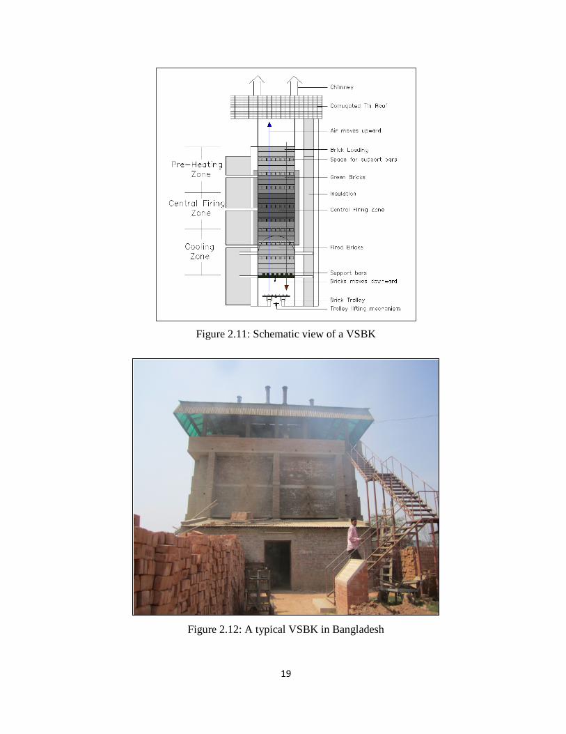
19
Figure 2.11: Schematic view of a VSBK
Figure 2.12: A typical VSBK in Bangladesh
20
Unlike FCK, VSBK has a permanent structure and can produce bricks throughout the year. It has
a design life of 8 to 10 years with minimum maintenance requirement (Practical Action 2010).
The greatest benefit of VSBK is, as the kiln constructed vertically, it is very economical in
utilizing space. In VSBK, pulverized coal up to 50% of the total fuel demand can be mixed with
clay as internal fuel. The rest of the coal is charged along with the green bricks in the loading
process. The charged coal that enters the firing zone slowly tends to burn completely and thus
providing a higher efficiency and less pollution. This is a contrast in comparison to other coal-
fired kilns, where coal is charged in a regular interval. Operation of VSBK requires more skilled
labor. Brick unloading can be a challenge because bricks tend to crack if withdrawn quickly from
the hot kiln. However, VSBK bricks satisfy typical standard related to compressive strength and
water absorbency despite its dull color compared to FCK bricks. A typical operating VSBK is
shown in Figure 2.12.
2.4.5 Tunnel kiln
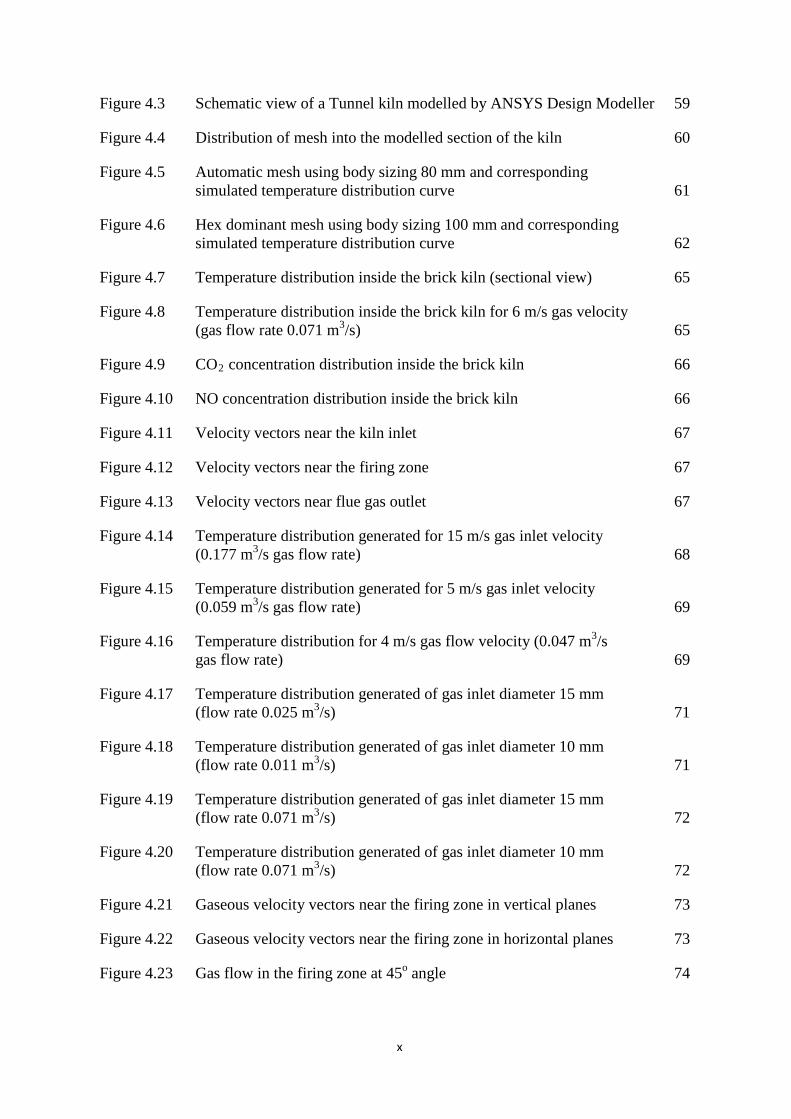
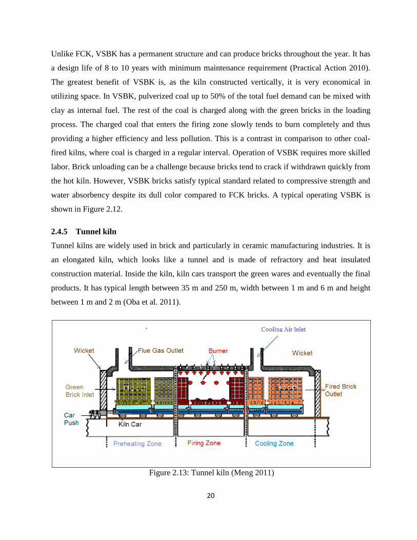
Tunnel kilns are widely used in brick and particularly in ceramic manufacturing industries. It is
an elongated kiln, which looks like a tunnel and is made of refractory and heat insulated
construction material. Inside the kiln, kiln cars transport the green wares and eventually the final
products. It has typical length between 35 m and 250 m, width between 1 m and 6 m and height
between 1 m and 2 m (Oba et al. 2011).
Figure 2.13: Tunnel kiln (Meng 2011)

21
Tunnel kilns are continuously operated kilns that receive bricks on track-mounted cars called
kiln cars. These cars are fed into the kiln, one after another, and are pulled through the kiln’s
different drying and firing zones. In Tunnel kiln, green bricks are exposed to a sequence of heat
treatment cycles, moving slowly through various temperature zones over the kiln cars. These
cars are put on the tracks and enter the drying portion of the kiln in separate chamber where they
remain for about 48 hours to reduce the moisture content. Preheated green wares then enters into
the kiln from one end of the kiln, increase in temperature and undergoing of the sintering.
During sintering the atoms in the green brick diffuse across the boundaries of the particles,
fusing the particles together and creating one solid piece. The green wares become products and
move out of the kiln from the other end. In the firing zone of the kiln, the temperature is usually
between 850oC and 1250oC which needs to vary with the type of brick. In the preheating and
firing zones, the heat from the high temperature flue gas preheats the green ware. Therefore the
green ware temperature increases and the flue gas temperature decreases. After the removal of all
the products the empty kiln car is going to the other side of the kiln, to begin the next production
cycle. Usually 40 to 80 kiln cars remain at a time inside the Tunnel kiln (Yu 2007). To complete
a full cycle of brick burning inside the Tunnel kiln it requires 36 to 72 hours to achieve different
quality bricks and ceramics.
The traditional Tunnel kiln suffers from long production cycle, high energy intensity, relatively
high rejection rates (~10%), and low levels of automation – in many phases of the traditional
process, bricks are moved and stacked manually. However, Tunnel kiln is the most modern brick
kiln, has scope for high automation. Both coal and gas can be used as fuel. Though it produces
the best quality bricks but the cost is higher compared to other brick kilns. Since 1947, Tunnel
kilns are gradually replacing circular intermittent kilns. In recent years, Tunnel kiln has become
the most popular and commonly used kiln in developed countries as this kiln is highly automated
and requires less manpower.
The layout of a typical Tunnel kiln is shown in Figure 2.13, where the three temperature zones as
shown are: preheating, firing and cooling. The solid and gas temperature profile and flow
direction are also shown in the figure.

22
2.4.6 Comparative overview of different brick kiln technologies
This section compares different aspects of brick production from collecting raw materials to
making finished product of Fixed Chimney Kiln (FCK), Zigzag kiln, Coal based Hoffmann kiln
(HK) and Vertical Shaft Brick kiln (VSBK) are described in the following paragraphs.
Land requirement: Land requirement for a FCK or a Zigzag is about 3-4 acres whereas that for
a coal based Hoffmann Kiln (HK) is about 12 acres (CDM 2009). Higher land requirement for
coal based HK also ensures greater production capacity. Major part of the land requirement is
needed for brick molding, drying and other brick processing operations. If only the kiln portion
is compared then the land requirement for coal based HK is less than half compared to FCK. For
VSBK, land requirement is less than one-fourth of FCK for same amount of production
(Practical Action 2010). The high variation of cost for different category lands has made this a
vital issue for entrepreneurs for selecting the type of kiln.
Fuel requirement: Coal is the only option for brick industries in countries where natural gas is
low in supply. Those previously constructed Hoffman kilns are barely using natural gas as fuel
and the consumption rate is 15,000-17,000 m3 per 100,000 bricks (Clean Energy Alternative
2011). Considering energy consumption requirement, coal based HK is more efficient than FCKs
and Zigzag kilns. The coal requirement for FCK is around 24 ton per 100,000 brick production
(World Bank 2011). Zigzag kiln and coal based HK consume around 18 and 14 ton coal per
100,000 brick production, respectively (CDM 2007). VSBK is the most fuel-efficient,
consuming least fuel around 10 ton of coal for 100,000 bricks (Practical Action 2010).
Brick quality: Hoffman kilns produce better colored bricks because of gas burning. Bricks from
coal based HK have also good color and shape and duly get higher price in the market. VSBK
cannot produce very good quality bricks as green bricks cannot be fired for long time inside the
kiln. Vertical structure of this kiln may cause load variance resulting cracks in bricks if fired for
a long time. So, strong bricks which are locally known as “pickets” and used instead of stone for
concreting cannot be produced by VSBK. Bricks from Zigzag and FCK are of same average
quality generally produced.
Investment opportunity: In terms of initial investment, FCK, Zigzag or VSBK require
expenditure in the range of US$ 50,000 to 70,000 (Practical Action 2010). The conversion of

23
FCK to Zigzag requires only US$ 30,000 and thus not much burden and uncertainty to future
business and return.
Hoffmann kiln is quite expensive requiring an initial investment of at least US$ 600,000. Coal
based HK also requires an initial investment of about US$ 600,000 to 700,000 (Clean Energy
Alternatives 2011). One major reason for the cost-variance between coal based HK and
Hoffmann is, in coal based HK an additional drier is required to dry the green bricks by utilizing
the waste heat of the flue gases. This modification also reduces pollution to some extent. Similar
modification could be done for gas-fueled Hoffmann but due to its low pollution level, this
modification can be considered superfluous unless otherwise justified by economic analysis.
These kilns can operate round the year. Building Hoffmann kiln requires special expertise and
thus demands high skill engineering consultants.
Working capital requirement for FCK and Zigzag kilns is approximately US$ 20,000 to 22,000
but for a Hoffmann it can go beyond US$ 100,000 because of higher inventory, maintenance and
overhead costs (CDM 2007).
Production rate: Hoffmann kiln has a production capacity of 7.5 to 9 million bricks per season
(CDM 2009). Coal based HK has a production capacity of around 15 million bricks as preheated
and dehydrated green bricks require less time for burning (CDM 2007). FCK and Zigzag have
approximately the same production capacity of around 2.5 million bricks per season as both the
kilns are usually built in the low-lying land (CDM 2007). An ordinary VSBK has a production
capacity of 2.7 million bricks and can operate all-round the year (Practical Action 2010). The
production capacity of VSBK can be increased several times simply by increasing the number of
kiln shaft.
To visualize the characteristics of the above comparative analysis easily, a number of mentioned
factors are shown in Table 5.4 below.
Emission: One of the major reasons of pollution from brick kilns is inadequate supply of air
during combustion. Blowers are added to Zigzag and coal based HK to ensure enough air supply
to kilns. In VSBK, air flows upward through natural convection. In Zigzag kiln, as air flows
through the zigzag path, the coarse particles are obstructed and settle before it is discharged into
the atmosphere. The combustion process improves as artificial draft is created by the addition of
blower. Also scrubbers are used to remove fly ash and SOx in the Zigzag kiln. In a scrubber, flue

24
gas is drawn into an underground water reservoir to clear solid particles before being released
into the atmosphere. Scrubbing water has to be changed regularly to ensure the system works
properly. However, brickfield owners often do not care as it requires additional workforce,
unless otherwise monitored regularly by the government agency.
Hoffmann kiln shows better performance than other coal burning technologies in terms of
pollution control. For coal based Hoffmann, flue gases are passed through dryer to preheat the
green bricks. Hard particles clear up largely from the flue gas since it is obstructed into the stacks
of green bricks. VSBK requires less fuel per brick basis, so automatically emits less.
Theoretically there should not be much black smoke from VSBK but sometime due to un-burnt
combustion, black smoke emits. Carbon dioxide emission from all four types of brick kilns is
estimated and shown in Table 5.5 for comparison. Detailed computation is shown in Appendix.
From this table, it is clear that VSBK emits least CO2 followed by coal based HK and Zigzag
than FCK.
Table 2.1: Comparison of various key factors for different brick kilns
Item FCK HK (coal) Zigzag VSBK
Land Requirement 16,000 m2 50,000 m2 16,000 m2 4,000 m2
Brick shape and color quality Medium Higher-medium Medium Low
Investment requirement (US$) 55,000 700,000 70,000 70,000
Working capital (US$) 22,000 100,000 22,000 22,000
Production rate/day 17,000 50,000 17,000 9,000
Production days/year 150 300 150 300
Coal required per 100.000 bricks 24 ton 14 ton 18 ton 10 ton
Table 2.2: CO2 emission comparison from different brick kilns
Item FCK HK (coal) Zigzag VSBK
Specific fuel consumption (TJ/brick) 4.02 ×10⁻⁶ 2.35 ×10⁻⁶ 3.02 ×10⁻⁶ 1.68 ×10⁻⁶
CO2 emission per 100,000 bricks (tCO2e)
38.06 22.20 28.54 15.86

25
2.4.7 Transition of Australian brick industry
In Australia, the early brick makers burnt their bricks in the open in a large heap which is
popularly known as the Clamp kiln. This type of kiln was used for more than thousands of years
throughout the world. Firewood or sometimes coal is used as fuel. This Clamp kiln was built of
bricks that were to be fired. Temperature was difficult to control in these kilns. The quality of
bricks produced from this kiln was unpredictable and generally poor. During the firing process
one fifth of the bricks were destroyed or were insufficiently fired and had to be fired again.
As the industry expanded, permanent kilns were built. The earlier ones were of the intermittent
type, which was, they had to be loaded, sealed, heated, cooled and unloaded for every firing.
Actually the kiln was subjected to intermittent heating and cooling. Many were of up-draught
design whether circular or square in size, with the furnace at the bottom and flue at the top. The
version of the up-draught model was simply a square box which was open at the top with firing
ports around the base. Up-draught kilns were wasteful of fuel, because a large portion of the
energy produced was simply released into the atmosphere. As the down-draught kiln was more
efficient it eventually replaced the up-draught kiln.
The kilns that eventually became quite popular in Australia were the down-draught type. The
size of this kiln was often rectangular in plan with a fixed roof; however some circular kilns were
also made. Furnaces at the sides sent the hot gases up the walls but then gases had to flow
downward between the bricks to exit via flues in the kiln floor. Flue gases were led underground
to a chimney stack nearby. This design was more efficient because the flame spent more time in
contact with the bricks. The down-draught kilns were reliable and long lasting and produced
attractive and well-fired bricks.
Coal or coke was adopted as the fuel in most large brick kilns. Wood also remained the preferred
fuel in these kilns. The down-draught kilns had a fuel to load ratio of about 1:5; that is a ton of
fuel was required for five tons of bricks (DENR 2008).
The mechanization of the brick work has been discussed in the 1860s and attempts were made to
produce brick machines and refine kiln design but these initiatives seemed to be experimental
that did not reach mass production or gain widespread practice. The Hoffman Company was the
first brickworks to introduce mechanization on a large scale (DENR 2008).

26
With the introduction of continuous kilns, there had been a fundamental change in the
technology of brick manufacturing. The Hoffman kiln having the continuous kiln design was
widely used in Australia. The principle of the Hoffman kiln anticipated the twentieth century
mass production. Though the original Hoffman kiln design had a circular plan, but they were
more frequently built as a rectangular plan with straight parallel sides and semi-circular ends in
Australia.
Hoffman’s first innovation was the introduction of mass production using steam-powered brick
machines and continuous burning inside the kilns. There was no guarantee that the company
could sell the output which was a new type and new size of brick. Also as the production method
was new in Australia there was no guarantee that the technology would work in the long run.
However, as the Hoffman kilns reduced the cost of brick production, it introduced an economy
of sale which brought a dramatic improvement in the efficiency of brick manufacturing.
Hoffman dominated the brick making industry in Australia from the First World War to the
1970s. The production was up to 300,000 bricks in a single firing. These kilns were also efficient
at that moment. Wastage of bricks in firing was negligible. Fuel-to-load ratio in a Hoffman kiln
was about 1:20 (DENR 2008). All the major brick making companies had to keep up the brick
supply to these kilns by installing wire-cutting or pressing machines. The capacity of the
Hoffman kilns encouraged mechanization of the brick industry. The efficiency of the Hoffman
kilns and the mechanization in the sector was the economic breakthrough that brought brick
manufacturing into the mass housing market.
The interesting thing about the technologies of this sector in the late nineteenth century and the
beginning of twentieth century was that it acted to de-skill the operation of the brickworks. At
the workers level, jobs were specialized into task specific work. Work was paid according to
production levels. Although significant elements of the brick production remained substantially
same as in the 1890s, there was evidence of modifications to the production process to
modernize it. In the 1940s many brick kilns converted from coal to oil firing, later when the oil
prices increased in the early 1970s, the kilns were converted to natural gas firing. The processes
here reflect the changing prices and availability of energy (Stuart 1989).

27
The first Hoffman was built around 1880s. The last Hoffman kilns went out of service in the
1980s in Australia, a century after the first one was built. Since the 1960s Hoffman kiln has been
replaced by another continuous type of kiln called Tunnel kiln.
After replacement of Hoffman kilns by Tunnel kilns in Australia, the performance of these
Tunnel kilns were improved over the years. Often the kilns were upgraded by introducing
efficient burners, automation in gas control of the burners, better insulation, reduction of heat
leakage, improving electrical demand control, adding doors to the end of the kiln, etc (Energy
Efficiency Opportunities 2007). Inefficient Tunnel kilns were also replaced by modern efficient
ones.
Business strategies of Australian brick industry
During the mid-nineteenth century, the brick industry was isolated on regional basis. Any excess
amount needed was supported by mobile brick-makers. Some brick-makers worked part-time as
brick manufacturing was not their main occupation. At the end of nineteenth century as railway
networks began to provide a regional transportation network, allowed the reduction of transport
costs to expand the market by providing incentive to mechanization. Many of the regional brick
kilns closed and the more efficient mechanized brick kilns were adopted in others. However
handmade brick kilns were not completely eliminated at that time. During the time of depression
in late nineteenth century, construction works virtually stopped and vicious price war occurred
(Stuart 1987). Large companies were forced to close down production and lay off workforce.
Handmade brickworks suffered the most from this situation.
To revive from this situation, brick industry formed co-operative organizations to share work and
regulate prices and quality. Formation of this co-operative organization caused high prices, poor
quality bricks, refusal to supply, and various other monopolistic activities. Government
sometimes tried to control the monopoly of the co-operative organizations by developing state-
run brick kilns. Sometimes disgruntled builders set up their own brick kilns to keep pressure on
the co-operative societies. Most of these incidents occurred during the first half of the twentieth
century. During present time the brick industry has undergone some significant transformation.
According to industry experts the sector has reached to its declining stage of life (Kelly 2012).
The issue that is going to affect this sector most is the current introduction of carbon tax.
Detailed impact of carbon tax to this industry is discussed in the following section.

28
Carbon price mechanism
The carbon price mechanism is going to be implemented in two stages. For the first three years,
starting from 1 July 2012, the price of each ton of carbon pollution is fixed, like a carbon tax.
Then, from 1 July 2015, the carbon pricing mechanism will move to an emissions trading
scheme where the price will be set by the market (Australian Government 2011). According to
the carbon price mechanism, the carbon price is now $23 for each ton of pollution beginning on
1 July 2012 (Frontier Economics 2011). The price will rise by 2.5 per cent a year during a three-
year fixed price period until 1 July 2015. The carbon price mechanism will then transition to an
emissions trading scheme where the price will be determined by the market. Around 500
businesses will be required to pay for their pollution under the carbon pricing mechanism.
According to the government, carbon price is the most cost-efficient way to cut carbon pollution
as putting a price on pollution will encourage companies to innovate and invest in new
technologies to use energy more efficiently.
Effect of carbon price in brick sector
Australian brick sector generates $1.1 billion revenue (in 2012), which is declining currently at a
rate of 2% between 2008 and 2013 (Kelly 2012). Profit from brick sector is $187 million while a
limited export earns $12.5 million only. Three companies share majority of the market of the
brick sector in Australia. Brickworks Ltd has the major share of 27% whereas Boral Ltd has a
share of 25% and CSR Limited has a share of 23%. A big portion of the brick industries are
located in Victoria whereas 25% is located in NSW, 18.8% in Queensland, 18.6% in Western
Australia, 6.3% in South Australia and 1% in Tasmania (Kelly 2012).
The principal output of this industry is clay bricks, which account for about 90% of industry
revenue and 85% of the volume of production. Premium bricks are being the main bricks used
for residential construction while the inferior quality bricks are satisfactory for use as non-facial
bricks, underground or support walls. The wholesale price of premium brick ranges from about
$475 to $600 per 1,000 and the bricks are delivered in strapped packs of 264 to 300 (Kelly
2011).
Collectively the brick industry employs 30,000 people, produces approximately 1.6 billion bricks
annually and contributes $2.6 billion to the Australian economy. The brick industry is also a

29
significant provider of apprenticeships and training with investment of over $3.5 million
annually (Kelly 2012).
The industry is currently considered to be moving into the declining stage of its life cycle, with
demand heavily dependent on cyclical fluctuations in residential construction investment. On the
top of it the industry is increasingly impacted due to the lower demand of bricks in the housing
construction. Brick market in Australia is facing difficult condition due to product substitution by
non-ceramic building materials, such as - timber, stone, concrete and steel (Kelly 2011).
As the brick industry operates within the building product market that includes a large number of
substitutes, it is hard for the brick industry to pass the carbon tax to the consumers as some of the
substitutes have significantly less emission compared to brick kilns. However, these substitutes
within the building product market vary greatly in their ability to provide energy efficient
housing or reduce the long-term emissions associated with maintenance and replacement.
Lightweight building products may have lower production emissions but require more
maintenance, need to replace more frequently and creates less thermally efficient buildings.
Whereas, bricks have higher production emissions but require almost no maintenance or
replacement and provide a more thermally efficient building. Hence it becomes a matter of
debate whether people should continue to use more bricks than other substitutes. Comparison of
CO2 generated per kg of clay bricks and some of the substitute products found from life cycle
assessment is presented in Table 2.3. This comparison clearly shows that clay bricks are emitting
less greenhouse gases compared to some of the substitute products.
Table 2.3: Bricks and some other substitutes’ emission comparison (Hammond 2008) Materials kgCO2 released per kg of production
Clay bricks 0.22-0.46
Concrete (AAC’s) 0.28-0.376
Timber 0.46-0.86
Stone 0.056-0.187
Steel 0.42-2.75
The capital costs in the brick industry are relatively high and no technology currently exists to
significantly reduce the emission intensity of the industry. Furthermore existing technologies,
which currently have life spans of 30-50 years, have no alternative usage to convert into low

30
carbon emission technology. The emission levels fluctuate with the building cycles between
1200 and 1500 tons of CO2-e per million dollars of revenue. (Think Brick Australia 2008).
The domestic market for clay bricks is also shrinking due to the trend toward smaller and higher
density dwellings. The impact of carbon price will be distributed differently across the building
product market and the brick sector will be affected significantly. Cheaper manufacturing cost of
bricks in Asia and other parts of the world will increasingly encourage import of bricks to
substitute local manufacturing. In Malaysia and other parts of Southeast Asia, the industry has
excess capacity to produce cheaper bricks. And the cheap transport cost means that the brick can
enter Australia and compete with local bricks. The brick industry in Australia estimates that
bricks used for internal walls can be imported from Malaysia at the price which is equal to
current price in Australian industry (Think Brick Australia 2008). So, increase in brick price due
to carbon tax will compel import from overseas. Thus there will be decrease in the size and
future investment in the Australian brick industry.
Ultimately the biggest problem that is going to be faced by the brick industry is by product
substitution. Though majority of the brick industry is controlled by three brick companies, a
significant fraction of the brick sector still includes many local manufacturers who service
regional Australia through investment and employment. These regional manufacturers will be
more impacted because of their inability to absorb costs. Passing of this cost to the buyers will
further increase product substitution.
2.5 Modelling Using Computational Fluid Dynamics (CFD)
2.5.1 Modelling
Computational Fluid Dynamics (CFD) is a computer-based tool for simulating the behavior of
systems involving fluid flow, heat transfer, and other related physical processes (Andersson
2012). It works by solving the equations of fluid flow (in a special form) over a region of
interest, with specified (known) conditions on the boundary of that region.
The set of equations that describe the processes of momentum, heat and mass transfer are known
as the Navier-Stokes equations. These partial differential equations have no known general
analytical solution but can be discretized and solved numerically. Equations describing other

31
processes, such as combustion, can also be solved in conjunction with the Navier-Stokes
equations (ANSYS 2009).
There are three major numerical methods that are used in CFD solutions – Finite Difference
(FD), Finite Volume (FV) and Finite Element (FE) methods. In FD, each nodal point of the grid
is used to describe the fluid flow domain. Taylor series expansions are used to generate FD
approximations to the partial derivatives of the governing equations (Tu et al. 2013). In FE the
governing equations are first approximated by multiplication with the shape functions before
they are integrated over the entire computational domain (Tu et al. 2013). The most common and
the one on which CFX is based, is known as the Finite Volume technique. In this technique, the
region of interest is divided into small sub-regions, called control volumes. The equations are
discretized and solved iteratively for each control volume. As a result, an approximation of the
value of each variable at specific points throughout the domain can be obtained. In this way, the
behavior of the flow can be identified.
2.5.2 Simulation steps using CFD
There are many commercial general-purpose CFD programs available, e.g. Fluent, CFX,
OpenFOAM, Flow 3D are few to cite. In all CFD programs the following steps in general are
followed to solve a particular problem. In this research to simulate Tunnel kiln performances
ANSYS CFX has been used. Figure 2.14 is showing the CFD simulation steps using available
any general-purpose CFD program including ANSYS CFX.
ANSYS CFX is the CFD software from ANSYS Inc. Solving any CFD problem using ANSYS
software package has to include ANSYS Workbench, ANSYS Design Modeller, ANSYS Mesh,
ANSYS CFX-Pre and ANSYS CFX-Post. Here, ANSYS Workbench is the platform where all
the components of the software can be linked up to solve a particular problem. The purposes of
other software components are mentioned later.
Geometry modelling
A simulation problem using CFD starts with a two-dimensional (2D) or three-dimensional (3D)
drawing of the geometry of the system. A Computer Aided Design (CAD) program is included in
all commercial CFD programs, however the geometry of the system can also be drawn separately
in any standalone CAD program and imported into the CFD grid-generation program. CAD

32
programs not designed for CFD often contains details that cannot be included in CFD simulation
drawing. The drawing must be cleaned before they can be included in the meshing program. For
this research, kiln geometry needs to be drawn in ANSYS Design Modeller.
Figure 2.14: Flowchart to show the simulation steps using CFD program
Grid generation (meshing) The equations for momentum transport are nonlinear which means that the computational
volume must be discretized properly to obtain an accurate numerical solution of the equations.
Accurate meshing of the computational domain is as important as defining the physical domain
as stated above. An ill conditioned mesh can give rise to very inaccurate results, so the quality of
Modelling of Geometry Defining geometry and boundary
Generating Mesh Divide the geometry into small computational cells
called mesh
Defining models Define models for turbulence, chemical reactions,
radiation, COx, NOx emissions etc
Set properties Heat transfer coefficient, temperature, velocity etc
Set boundary and inlet conditions Setting up initial conditions, inlet and outlet
conditions and wall conditions
Solve Chose iteration methods, transient or steady state,
convergence value to obtain results
Post-processing Analyze the result

33
the mesh, e.g. the aspect ratio and skewness must be evaluated prior to the simulation
(Andersson et al. 2012). This research on brick kiln has a complex geometry to draw at the
beginning and then requires consistent meshing. So several types of meshing needs to be
generated to find out whether the geometry is mesh independent. Meshing for this particular
problem is drawn in ANSYS Mesh.
Define models
For single-phase laminar flow the Navier-Stokes equations can be solved directly but for
turbulent and multiphase flows the user must select the most appropriate models. There are few
generally accepted models for turbulence and multiphase flows, but there are hundreds of models
to choose from (Andersson et al. 2012). For each model there are also several parameters that
must be set for proper simulation. Usually the default values are the best choice but in some
cases the user can find more suitable parameters to be chosen according to the problem in
consideration. In most commercial CDF programs it is also possible to write users own model as
a user defined subroutine/function (UDS/UDF). This research involves single phase turbulent
flow as gas and air react in combustion to generate heat and emissions all in gaseous phase. In
this regard appropriate models have to be selected for simulation. In ANSYS CFX these models
has to be chosen from options of CFX Pre. For turbulence modelling, k-epsilon model is chosen,
for radiation modelling P1 model is chosen, and methane-air reaction is chosen from ANSYS
library. Detailed descriptions of these models are given in Chapter 3.
Set properties of different parameters
All physical properties like viscosity and density of the fluids must be defined according to their
temperature and pressure distribution. Some are inbuilt into the CFD software or available in
their databases. It is also possible to write a UDS/UDF and added to the CFD program for
calculating the properties. However for this particular research, properties were selected from
options available in ANSYS CFX Pre. The chosen properties of different parameters are
described in Chapter 4.
Boundary and initial conditions
Boundary conditions must be defined including walls and other boundaries such as air inlet and
outlet temperatures, velocity, pressure, etc. Geometrical symmetries must also be defined.
Defining symmetry ensures less computation and hence quick result. Initial conditions for

34
transient simulations or an initial guess to start the iterations for steady-state must also be
provided. In this study, boundary conditions for kiln air inlet and outlet, gas inlet and outlet,
symmetry of the geometry have to be provided for computation. Also brick wall temperatures
have to be provided as an initial guess for proper estimation during subsequent iterations. These
values are given using ANSYS CFX Pre.
Solve
In CFD, the quality of an acceptable solution in terms of convergence criteria must also be
defined. Whether the fluid flows is steady or unsteady that also has to be mentioned for
computation. This particular problem involves combustion. Firing of Tunnel kiln burner once
started continues for months until operator shuts it for maintenance or emergency. Though
initially fluid temperature is unsteady, becomes steady quickly due to stability in gaseous flow
distribution. So it is considered that the simulation should be performed under steady-state
condition. For high accuracy convergence value is given as 1×10⁻⁴. In CFD the equations for
continuity, momentum, energy, radiation and combustion are solved simultaneously. After
solution, results at different format can be viewed in CFX Post.
Post-processing analysis
The first objective in the post-processing is to analyze the quality of the solution. It has to be
found out whether the solution is independent of the grid size or the convergence criterion. It has
to be checked whether proper turbulence model and boundary conditions were chosen. Analysis
of the final simulation results can give local information about resulting fluid flows, temperature
distribution, emission generated, etc. In this study, it has been checked whether the simulation is
independent of generated mesh or grid size. In ANSYS, post processing analysis can be
performed using CFX Post.
2.6 Importance of Using CFD Analysis in Brick Kilns
Previous researches in this field
An in-depth review of the available literature reveals that not many researches applied
Computational Fluid Dynamics (CFD) to evaluate the performance of fuel combustion inside a
brick kiln. Most of the research found on the application of CFD in Tunnel kiln is related to
realize the combustion situation and how to improve the burner efficiency (Sheng et al. 2004;

35
Hauck 2005). Majority of these simulations are modelled in two dimensions; three-dimensional
modelling was largely overlooked due to complexity. Research is also conducted to find out the
optimum placement of the burner (Hauck 2005). There are quite a few researches where
mathematical models of the cooling, preheating and firing zones of a Tunnel kiln were developed
to increase its efficiency (Mancuhan 2009; Kaya et al. 2007, 2008, 2009). There are researches
that considered the emission performances of kilns/burners used for other sectors. CFD
application in similar other sectors include optimizing the design of different types of burners
and emission performances (Chacon et al. 2007), drying and thermodynamic processes
(Jamaleddine et al. 2010; Rasul et al. 2007), gas flow mixing, secondary airflow analysis (Yang
et al. 1999; Purimetla et al. 2009), etc. CFD is also used in combustion related problems
including prediction of field of combustion for coal burner in rotary kiln (Ai-chun et al. 2006),
and coal-air balancing in power plant (Vijapurapu et al. 2006). Heat transfer efficiency of
counter travelling Tunnel kiln was analyzed where the brick stacks move in opposite directions
in two side by side tunnels (Meng 2011). This method of heat transfer in counter travelling
Tunnel kiln is popularly known as solid-solid recuperation. In this method, heat is extracted from
brick body by air and is released to the other counter travelling Tunnel kiln. Simulation is also
conducted for analyzing the flow in Hoffman kiln (Garcia et al. 2006). Though there are few
researches that evaluated the performance of a Tunnel kiln using CFD analysis (Meng 2011;
Sheng et al. 2004; Hauck 2005), but none of them considered emission performances of those
kilns. However, researches that considered emission performances of those kilns didn’t include
CFD simulation (Co et al. 2009; Maithel et al. n.d.; Greentech knowledge solutions 2012). Few
researches also tried to identify the optimum Tunnel kiln curve for various ceramic products
(Durakovic et al. 2006; Oba et al. 2011; Atanasov et al. 2007). Industries emphasize on optimum
Tunnel kiln curve for obtaining various quality bricks and ceramics. So, from the generated
Tunnel kiln curve point of view, brick kiln design need to be optimized.
Research Gap
From the literature review, it has been identified that there is no such research that focused on
optimizing the Tunnel kiln design for typical clay bricks using CFD simulation. So the research
question is - what is the optimum temperature distribution curve for the Tunnel kiln to ensure
efficient fuel usage and thus can reduce emission?
36
Significance of this research
The purpose of this research is to use this popular tool to evaluate the performances of the brick
kiln in three dimensions and identify ways to improve its emission performance. Incomplete
combustion and emission are related to improper kiln/burner design. Emissions to air from
natural gas fired kilns usually consist of carbon-dioxide, carbon monoxide (COx), sulphur
dioxide (SO2), sulphur trioxide (SO3), oxides of nitrogen (NOx), gaseous fluoride/chloride
compounds, particulate matters, etc. ANSYS CFX has its own library for few common reactions.
Reaction between methane and air can be found from that library. That equation does not
consider SOx or chloride, fluoride emissions. Also the composition of gas used by various
competitors in the industry may vary according to the location of the factory and available gas
source nearby. So for problem simplification, only NOx and COx emissions from the brick kilns
are investigated using available reaction equation from ANSYS library.
Brick kiln environment is drawn in 3D using CFX Design Modeller. Appropriate turbulence,
emission, radiation, and combustion models are identified from previous researches
(Jamaleddine et al. 2010; Chacon et al. 2007). Inlet and outlet cross-sectional areas, velocities,
air temperatures, stack bricks heat transfer coefficient and its initial guess of temperature and
other properties along with fuel composition are provided as input.
As Computational Fluid Dynamics simulation is an integral part of this research, in the following
chapter, detailed Computational Fluid Dynamics theories and the relation of these theories for
this problem is explained. Also, how these theories can be implemented in this case using
ANSYS CFX is described.
2.7 Summary
Brick is the chief construction material worldwide and is considered as a weight bearing or
partitioning building unit. The processes of manufacturing brick include extraction of clay,
moulding and shaping, drying and firing and cooling to finished product. Firing is a key process
in the production of bricks, as it controls the vitrification process and is usually completed by
1050oC for ordinary building bricks.
There are different types of kilns for brick production from ancient times. Tunnel kiln is operated
in developed countries whereas Fixed Chimney, Zigzag, Hoffman, Vertical Shaft Brick Kiln

37
(VSBK) operate in developing countries. Tunnel kiln is evaluated in this research to improve its
performance.
Computational Fluid Dynamics (CFD) is a computer-based tool for simulating the behavior of
systems involving fluid flow, heat transfer, combustion, and many other processes. CFD
simulation involves modelling geometry, generating mesh, defining models, setting parameter
properties, and boundary and initial conditions, solving and post-processing. The purpose of this
research is to use this popular tool to evaluate the performance of the Tunnel kiln in three
dimensions and identify ways to improve its performances.

38
Chapter 3
Computational Fluid Dynamics Modelling using ANSYS CFX
3.1 Introduction
Computational fluid dynamics (CFD) is used to simulate fluid flow characteristics. CFD
simulation without proper knowledge can be a very uncertain tool. The commercial CFD
programs have many default settings and can almost always give results from the simulations,
but to obtain reliable results the model must be chosen with a logical methodology. A converged
solution displays the results of the specifically chosen models with the given mesh. However it
may not reveal the truth. Without proper understanding of the CFD program and the modelling
theories behind it, CFD can be limited to colorful fluid display. To understand CFD simulation
properly, fluid flow characteristics needs to be understood along with the provided options of the
CFD software.
3.2 Fluid Flow Characteristics
From the CFD modelling point of view it is useful to separate possible flows into the following
categories: laminar-turbulent, steady-unsteady-transient and single phase-multiphase.
The highly ordered fluid motion characterized by smooth layer of fluid is called laminar. In
laminar flow the Navier-Stokes equations that describe the momentum transport of flow, is
dominated by viscous force. It is possible with CFD to obtain very accurate flow simulations for
single-phase laminar flow. On the other hand the highly disordered fluid motion that typically
occurs at high velocities and is characterized by velocity fluctuations is called turbulent. The
Navier-Stokes equations describe turbulent flows, but, due to the properties of the flow, it is
seldom possible to solve the equations analytically for real engineering applications. From CFD
simulation it is possible to closely predict the characteristics of a turbulent flow. Air and gas
flows inside the brick kiln are turbulent in nature; hence the characteristics of turbulence are used
to analyze the flow inside the kiln. However flows from turbulent to laminar and from laminar to
turbulent (i.e. transitional flow) are difficult to simulate accurately (Andersson et al. 2012).

39
Steady flow is a flow that has no change at a point with time. A flow that is not steady is known
as unsteady flow whereas, developing flows are considered as transient flow (Cengel et al.
2010). Brick kiln fluid flows however are not steady at the initial stage of firing when flows are
yet to become stable. In course of time, temperature distribution inside the kiln becomes steady
quickly due to stability in fluid flow.
Single phase flow consists of gas-gas or liquid-liquid systems. Very accurate solutions are
obtained if single-phase laminar flow is simulated using CFD. If the flow is turbulent, in most
cases satisfactory flow simulations can be obtained. The main problem is usually related to
simulation of the mixing of reactants for fast reactions in laminar or turbulent flow (Andersson et
al. 2012). When the reaction rate is fast compared to the mixing, a model for mixing along with a
chemical reaction must be introduced. Combustion in the gas phase belongs to this category. In
this study, the flow of air reacting with gas forms a single gaseous phase, which eventually
releases heat to the object under consideration. In the process separate reaction equation was
included which was solved simultaneously with the problem of gas and air mixing.
Multiphase flow may consist of gas-liquid, gas-solid, liquid-liquid, liquid-solid or gas-liquid-
solid systems. For multiphase system containing very small particles that follow the continuous
phase closely, reasonable simulation results can be obtained by CFD (ANSYS 2009). Systems in
which the dispersed phase has a large effect on the continuous phase are more difficult to
simulate accurately. Such as coal particles sprayed in gaseous mixture. Lack of good multiphase
model deteriorates the quality of simulation. For gaseous combustion, multiphase flow is not
necessary, however if coal based combustion is simulated then multiphase model is essential. In
this particular research, only gas fueled kiln is considered. So, single phase flow is adequate for
the simulation. However, if the coal fired kilns are considered then the characteristics of
multiphase flow also needs to be considered.
3.3 ANSYS CFX
ANSYS CFX, a Computational Fluid Dynamics (CFD) software, combines advanced solver with
powerful pre- and post-processing capabilities. It includes: a solver that is both reliable and
robust; full integration of problem definition, analysis, and result presentation. It also has an
intuitive and interactive setup process and uses menus and advanced graphics (ANSYS 2009).
ANSYS CFX is capable of modelling: steady-state and transient flows, laminar and turbulent

40
flows, heat transfer and thermal radiation, transport of non-reacting components, combustion,
particle tracking, etc.
3.3.1 Geometry modelling
The geometry of the fluid domain where the analysis can be performed is drawn using ANSYS
Design Modeller. Often geometries can be drawn in other CAD software and then can be
imported in ANSYS. However, geometries drawn in other CAD software may contains details
that cannot be included in CFD simulation drawing and may require correction. So, it is better to
use built-in drawing software ‘Design Modeller’ of ANSYS for modelling the geometry.
3.3.2 Meshing process
After drawing the geometry, it is discretized into small cells using ANSYS Mesh. Meshing can
be accomplished in any geometry by the following steps. Figure 3.1 is showing how meshing is
accomplished using ANSYS Mesh.
Figure 3.1: Meshing process
A proper meshing method need to be chosen at the beginning. Global mesh settings have to be
specified which means what type of mesh is going to be generated to the overall geometry. Then
local mesh settings are inserted if required. The part of the geometry with more importance may
get higher spatial resolution by local mesh setting. Higher resolution means the number of local
elements in that particular part can be increased by sub-dividing the larger elements.
Set physics and meshing method
Specify global mesh settings
Insert local mesh settings
Preview and generate mesh
Check mesh quality

41
Consequently, after generating the mesh, mesh quality needs to be checked. Mesh quality is
extremely important for proper simulation. Better quality mesh ensures accurate result of the
simulation.
Different 2D and 3D shapes formed by ANSYS Mesh are shown in Figures 3.2 and 3.3. There
are five meshing methods available in ANSYS Mesh for 3D geometries. Tetrahedral method can
be used to generate tetrahedral elements. Sweep method can be used to generate prism or
hexahedral mesh for sweepable bodies. Hex dominant method is recommended for bodies that
cannot be swept. A quad dominant surface mesh (as shown in Figure 3.3) is created first and then
Hex mesh is used to fill most of the domain, and pyramid and tetrahedral meshes for rest of the
domain. Multizone method mainly contains hexahedral elements in different defined zones.
Automatic method combines multiple methods based on complexity of geometry. It is a
combination of tetrahedrons (patch conforming) and sweep methods. This method automatically
detects volumes that can be meshed with sweep method. Volumes that cannot be meshed using
sweep method are meshed using tetrahedron method with patch conforming algorithm.
Figure 3.2: 3D elements formed by meshing methods
There are four meshing methods for 2D geometries available in the ANSYS Mesh as shown in
Figure 3.3: Automatic method (Quad dominant), Triangles, Uniform Quad/Tri and Uniform
Tetrahedral Pyramidal
Prismatic (Wedge) Hexahedral

42
Quad. The shapes as shown are self-evident to explain their advantages and disadvantages for
use in the geometries.
Figure 3.3: 2D shapes formed by meshing methods
After the generation of the mesh, mesh quality has to be checked. If the mesh quality is not of
desired level for a particular method then other methods can be selected judiciously. Sometimes
complicated geometry cannot be meshed using a particular mesh method. In that case, a different
mesh method has to be chosen to generate mesh for that geometry. This geometry on Tunnel kiln
is a three-dimensional body. Different 3D meshing options has been considered. Due to the
complexity of the geometry, not all methods could generate mesh in this geometry. Hex
dominant and Automatic methods are used to generate mesh in this geometry. After the
generation of mesh, mesh quality was checked and mesh independency was analysed as
explained later.
Mesh controls
Sometimes automatically generated mesh does not have adequate number of nodes or elements.
In that case the number of nodes and elements can be increased by local and global mesh
controls. Global mesh settings can be controlled using the following options: sizing, defeaturing,
statistics, advanced options etc.
Advanced sizing functions Advanced sizing function is used to control the size of mesh. This is an important tool to
generate appropriate sized mesh required for faultless and effective simulation. Advanced sizing
function controls the growth and distribution of mesh in important regions of high curvature or
close proximity of surfaces. Five options of advanced sizing functions are as follows: Off – the
edges are meshed with global element size computed by the Mesher. The edges are refined for
Triangle (Tri) Quadrilateral (Quad)

43
curvature and 2D proximity. At the end, corresponding face end volume mesh is generated.
Curvature – determines the edge and face sizes based on ‘curvature normal angle’ which is the
maximum angle between adjacent face normals. Finer curvature normal angle creates finer
surface meshes. Proximity – controls the mesh resolution on proximity regions in the model. It
fits in specified number of elements in the narrow gaps. Higher number of cells across gap
creates more refined surface meshes. Proximity and curvature – combines the effect of proximity
and curvature size function. Fixed – constant mesh size throughout, no refinement due to
curvature or proximity in the model. Surface mesh is generated with maximum face size.
Volume mesh is generated with specified maximum size.
As proximity and curvature gives better meshing by controlling of the sizes, this option was
chosen for this geometry. Due to the complexity of the geometry, ‘Fine’ mesh option under
proximity and curvature could not be chosen for this geometry because the program ran out of
memory. Instead ‘Coarse’ mesh option was chosen.
Element size
Defining element size is important to increase the number of elements and nodes. Element size
can be defined for the entire model. This size is defined for meshing all edges, faces and bodies.
A particular size for elements can be mentioned as per geometry dimensions. During meshing for
this geometry, for global mesh controls, element size was chosen as 100 mm after several trial
and error runs of the model. The local meshing can be controlled locally by scoping a
combination of the following options to the geometry: sizing, refinement, face-meshing,
inflation, etc. For local mesh control, a sizing of 65-80 mm was chosen for selected faces of this
geometry.
3.3.3 Checking mesh quality
A good quality mesh is very important in order to minimize the errors in the solvers leading to
numerical diffusion and incorrect results. A good mesh has 3 components: good resolution,
appropriate mesh distribution and good mesh quality. The first two components depend on the
overall meshing process and the user’s meshing strategies to conduct a specific type of analysis.
ANSYS Mesh can quantify the mesh quality using several quality criteria and tools. It is very
important to generate a mesh displaying good quality matrices as a necessary condition.

44
Figure 3.4: Measuring orthogonal quality
Orthogonal quality (OQ)
Orthogonal quality is a special quality of generated mesh which is defined by the following two
equations:
For a cell it is: ii
ii
ii
ii
cAcA
fAfA ⋅×
⋅ computed for each face i
For the face it is: ii
ii
eAeA ⋅ computed for each edge i.
where Ai is the face normal vector and fi is a vector from the centroid of the cell to the centroid
of that face, and ci is a vector, ei is the vector from the centroid of the face to the centroid of the
edge as shown in Figure 3.4 (Leap Australia 2010). Perfect orthogonal quality is 1 whereas the
worst orthogonal quality is 0. During solving this problem, from various mesh generation it was
found that orthogonal quality was close to 0.8.
Skewness
Skewness is another characteristic to determine the quality of meshing. Perfect skewness value is
0, whereas worst skewness value is 1. In this modelling, it was found after mesh generation that
skewness was very close to 0. There are two methods of determining skewness (Leap Australia
2010): i) Equilateral volume deviation, where skewness is defined as
A1 c2
c3
c1 f1
f2
f3
A3
A2 e3
e2
e1 A2
A3
A1

45
sizecelloptimalsizecellsizecelloptimal
Skewness −
= (3.1)
This equation applies only for triangles and tetrahedrons. Figure 3.5 shows how skewness is
measured. ii) Normalized angle deviation, where skewness is defined as
−−−
=e
e
e
e
θθθ
θθθ minmax ,
180max Skewness
(3.2)
where θe is the equiangular face/cell (60 for tets and tris, and 90 for quads and hexas). ϴmax and
θmin can be found from the Figure 3.6. ϴmax and θmin are the maximum and minimum angles
between any two edges of the cell, and ϴe is the angle between any two edges of an ideal
equilateral cell with the same number of edges (Cengel et al. 2010). In CFX, the vertex of the
mesh-element is the centre of the solver-element as shown in Figure 3.7.
Figure 3.5: Measuring skewness
Figure 3.6: Measuring ϴmax and θmin
θmax
θmin
Actual cell
Circumsphere

46
Figure 3.7: Solver element for vertex-centered scheme
Orthogonality, Aspect Ratio and Expansion Factor CFX solver calculates these three important measures of mesh quality at the start of a run and
updates them each time the mesh is deformed.
Figure 3.8: Defining orthogonality
Orthogonality measures alignment of: ip-face normal vector = n, node to node vector = s as
shown in Figure 3.8. Orthogonality factor > 1/3 is desirable and orthogonality angle > 20o is
desirable. Aspect ratio measures how stretched a control volume is as shown in Figure 3.9.
Aspect ratio = maximum of the ratio of largest to smallest ip-areas for each element surrounding
a node, where < 100 is desirable (Leap Australia 2010).
Figure 3.9: Defining aspect ratio
Amax/Amin
ip2
ip1
s
n
n, s

47
Expansion factor measures how poorly are the nodal position corresponds to the control volume
centroid as shown in Figure 3.10. Mesh expansion factor = ratio of largest to smallest element
volumes surrounding a node, where < 20 is desirable (Leap Australia 2010).
Figure 3.10: Defining expansion factor
After generating mesh of the Tunnel kiln geometry, it was found that orthogonality, aspect ratio
and expansion factor had desired values.
3.4 Equations in ANSYS CFX
3.4.1 Continuity, momentum and energy equations
The momentum and continuity equations need to be solved for CFD simulation. The equation of
the conservation of mass or continuity can be written as follows:
𝜕𝜌𝜕𝑡
+ ∇ (𝜌) = 𝑆𝑚 (3.3)
Conservation of momentum in an inertial reference frame is given by:
𝜕𝜕𝑡
(𝜌) + ∇(𝜌) = −∇𝑝 + ∇(𝜏) + 𝜌 + (3.4)
where 𝜌 is the density, is the velocity, 𝑆𝑚 is the source term, p is the static pressure (Pa), 𝜏 is
the stress tensor, is the external body forces, is the gravity, t is the time (Chacon et al.
2007).
Energy equation needs to be solved if heat transfer is included in the problem. As this research
contains combustion and heat transfer related issues so energy equation needs to be incorporated.
Heat transfer in a fluid domain is governed by the energy equation given below:
Min sector
volume
Maximum sector volume
dmax dmax

48
𝜕𝜕𝑡
(𝜌𝐸) + ∇𝑣 (𝜌𝐸 + 𝜌) = ∇ 𝑘𝑒𝑓𝑓∇𝑇 − 𝛴ℎ + 𝜏𝑒𝑓𝑓𝑣 + 𝑆ℎ (3.5)
where 𝐸 is the energy term, 𝑣 is the velocity, 𝜌 is the density, 𝑘𝑒𝑓𝑓 is the effective turbulent kinetic
energy, T is the local temperature in Kelvin, h is the enthalpy for ideal gas, 𝐽 is the diffusion
flux, 𝜏𝑒𝑓𝑓 is the effective stress tensor, 𝑆ℎ is the volumetric heat source term, t is the time
(Chacon et al. 2007). Different options selected in ANSYS CFX solve the above equation in different ways. If ‘None’
is selected in the CFX Pre then energy transfer equation is not solved. While ‘Isothermal
properties’ are selected, the energy transport equation is not solved. However, a temperature is
required to evaluate consequent fluid properties. ‘Total energy’ option models the transport of
enthalpy and includes kinetic energy effects. It should be used for gas flows and high speed
liquid flows where kinetic energy effects become significant. For multi-component flows,
reacting flows and radiation modelling, additional terms need to be included in the energy
equation. If ‘Thermal energy’ is selected, an energy transport equation is solved which neglects
variable density effects. In this modelling objective, thermal energy is the most suitable option to
solve the problem.
3.4.2 Radiation model
Radiation effects should be considered when Qrad = (Tmax4 - Tmin
4) is significant compared to
convective and conductive heat transfer rates. In this particular research convective heat transfer
is significant compared to conductive and radiative heat transfer.
To find out the effect of radiation, Radiative Intensity Transport Equations (RITEs) are solved.
Several radiation models are available in ANSYS CFX which provides approximate solution to
the RITEs. Each radiation model has its own assumptions, limitations and benefits. In ANSYS
CFX there are four models available – i) Rosseland model, ii) P1 model, iii) Discrete transfer
model, and iv) Monte Carlo model.
Before choosing a radiation model, it needs to be found out whether the fluid is transparent to
radiation at wavelengths where the heat transfer occurs or whether that fluid absorbs and re-emits
the radiation. If the fluid absorbs and re-emits radiation then P1 model is a good choice. Many
combustion simulations fall into this category since combustion gases tends to absorb radiation.
P1 model gives reasonable accuracy without too much computational effort. This model has

49
proved adequate for the study of fuel flames, in regions away from the immediate vicinity of the
flame. However, it has been used for lower temperature values with varying success. The
radiative transfer equation adopted for an absorbing, emitting and scattering medium at position
𝑟 in the direction 𝑠 is:
𝑑𝐼 (𝑟.𝑠)𝑑𝑠
+ (α + 𝜎𝑆) I (𝑟. 𝑠) = αn2 𝜎𝑇4
𝜋+ 𝜎𝑠
4𝜋 ∫ 𝐼(𝑟. 𝑠)ɸ(, 𝑠)𝑑𝛺4𝜋0 P
(3.6)
where I is the radiation intensity, 𝑟 is the position vector, 𝑠 is the direction vector, is the
scattering direction vector, α is the absorption coefficient, σ is the Stefan-Boltzmann constant, n
is the coefficient of excess of air, T is the local temperature in Kelvin, 𝜎𝑆 P
is the scattering
coefficient, ɸP is the phase function, Ω is the solid angle, G is the incident radiation, C is the
linear anisotropic phase function coefficient, t is the time. (Chacon 2007).
The following equation is obtained for the radiation flux:
𝑞𝑟 = 13(𝑎+𝜎𝑠)−𝐶𝜎𝑠
∇𝐺 (3.7)
If the fluid is transparent to radiation at wavelength where the heat transfer occurs then Monte
Carlo or Discrete transfer models (DTM) may also be used. DTM can be less accurate in models
with long/thin geometries. Monte Carlo uses the most computational resources, followed by
DTM. As this particular research involves simulation of combustion so P1 model is selected.
For effective heat transfer, proper defining of boundary conditions are essential. For inlet, static
temperature or total temperature has to be given. For opening, opening temperature or opening
static pressure has to be provided. Wall can be selected as fixed temperature, adiabatic, heat flux
or heat transfer co-efficient. Sometimes, if outlet is assigned in ANSYS CFX, it causes error in
computation. In such cases “Opening” is selected which allows fluid either enter or exit the
domain as per the prevailing condition.
Natural convection occurs when temperature differences in the fluid result in density variations.
For heat transfer problems, sufficient iterative computation time has to be allowed for heat
balance simulation. Wall heat transfer coefficient hc usually depends on the wall adjacent
temperature. Wall heat flux qw is the total heat flux into the domain by convective and radiative
processes.

50
3.4.3 Turbulence
Turbulence is unsteady, irregular motion in which transported quantities (mass, momentum,
scalar species) fluctuate in time and space. Fluid properties and velocity exhibit random
variations. Theoretically all turbulent and laminar/transition flows can be simulated by numerical
solution of the full Navier-Stokes equations. A large number of turbulence models are available
in CFX, some have very specific applications while others can be applied to a wider category of
flows. The velocity near the wall is important. Turbulence models are generally suited to model
the flow outside the boundary layer.
Turbulence models are used to predict the effects of turbulence in fluid flow. There is no
turbulence model that has universal acceptability of dealing with all problem areas. The choice
of turbulence model depends upon various considerations such as flow characteristics, level of
accuracy, available computational resources, and time availability for simulation. To make the
most appropriate choice of a model for the brick kiln, it was necessary to understand the
capabilities and limitations of those various models discussed below.
A number of models have been developed that can be used to approximate turbulence. Some of
these have very specific applications, while others can be applied to a wider class of flows. The
turbulence models available in CFX are: k-ω model, Standard k-ε model and Shear Stress
Transport (SST) model, etc.
Standard k-ε model
Standard k-ε model offers a good compromise between numerical effort and computational
accuracy. Limitations of this model are due to inaccuracies with swirl flows and flows with
strong streamline curvature ANSYS (2009).
For this particular study, k-𝜖 model has been selected. The k-𝜖 model equations can be expressed
as follows:
𝜕𝜕𝑡
(𝜌𝑚𝑘) + ∇(𝜌𝑚𝑣𝑚 𝑘) = ∇ (𝜇𝑡𝜎𝑘∇𝑘 + 𝐺𝑘,𝑚 + 𝐺𝑏 − 𝜌𝑚𝜖 (3.8)
𝜕𝜕𝑡
(𝜌𝑚𝜖) + ∇(𝜌𝑚𝑣𝑚 𝜖) = ∇ 𝜇𝑡,𝑚𝜎𝜖
∇𝜖+ 𝜖𝑘
(𝐶1𝜖𝐺𝑘,𝑚 − 𝐶2𝜖𝜌𝑚𝜖) (3.9)

51
where, 𝜌𝑚 is the mixture density, 𝑣𝑚 is the velocity, 𝜇𝑡 is the turbulent viscosity, 𝐺𝑘,𝑚 is the
production of turbulence kinetic energy, 𝐺𝑏 is the production of turbulence kinetic energy
because of buoyancy, k is the turbulent kinetic energy, 𝜖 is the turbulent dissipation rate, 𝐶 is the
linear anisotropic phase function co-efficient, 𝜎𝑘 and 𝜎𝜖 is the scattering coefficient for k and 𝜖, t
is the time (Chacon et al. 2007).
k-ω model
This model has few advantages among which are the near wall treatments for low-Reynolds
number computations. Low Reynolds number computation means the near wall mesh is fine
enough to resolve the laminar part of the boundary layer which is very close to the wall.
Shear Stress Transport (SST) model
The SST model is based on the k-ω model and has the same automatic wall treatment like k-ω
model. This model properly calculates the transport of the turbulent shear stress and gives high
accurate predictions. It can also predict on the amount of flow separation.
3.4.4 Combustion models
Combustion models in CFX use the same algorithm used for Multi-component Fluid with the
addition of heat source/sink term due to chemical reactions. In CFX available combustion
models are: i) Eddy dissipation model (EDM), ii) Finite rate chemistry (FRC) model, iii)
Combined EDM/FRC, iv) Laminar flamelet (or Flamelet) model, and v) Burning velocity model.
The combustion rate is dominated by the rate of mixing of the materials. Due to the fact that the
methane and air undergo fast reaction combustion, so the finite rate chemistry model is not a
suitable model for the combustion in this particular case. The Combined EDM/FRC model has
lot of similarity with the EDM and has no benefit over the EDM in this case. In fact, the
convergence behavior of the Combined EDM/FRC model may be worse than that of the EDM
according to ANSYS (2009).
The EDM, the Laminar flamelet model and the Burning velocity model are suitable for “fast”
combustion modelling. The Burning velocity model is a part of the Flamelet model with some
extra capability which is not considered here. So the extra capability of the Burning velocity
model is not required and therefore it is sufficient to use the Flamelet model for this brick kiln
simulation.

52
The EDM tracks each individual chemical component with its own transport equation. This
model is flexible in a way that any new materials could be added. A limitation of this model is
that intermediate species such a CO cannot be calculated with adequate accuracy. This may lead
to over-prediction of flame temperature, usually in fuel-rich regions. The Flamelet model can
simulate the products of incomplete combustion. For this reason it generally provides a more
accurate solution than the EDM. However, one drawback of the Flamelet model is that it requires
the availability of a Flamelet library for the required fuel/oxidizer combination over the pressure
and temperature ranges of interest.
Fluid properties, including temperature and density, are computed from the mean composition of
the fluid in the same way as for other combustion models, such as the EDM. In the Flamelet
model, the effect of heat loss and pressure on density and temperature is taken into account.
NO Model
The NO model calculates mass fractions of NO formed in the combustion process. The NO
formation model is fully integrated into the CFX reaction and combustion module. NO
concentrations are typically very low and combustion is negligible. The NO is created or
destroyed through four mechanisms: Thermal NO, Prompt NO, Fuel Nitrogen, and NO Re-burn.
The fuel nitrogen mechanism only affects coal and oil combustion (Chacon et al. 2007). The
Flamelet model utilizes post-processing in solving the concentration of NO. This post-processing
can be coupled to the main solution so that the formulation of NO is driven by the main solution
but is not going to affect the main solution. This approach is appropriate for the simulation
because the mass fraction and reaction rate of NO are sufficiently small, so the effect on the main
solution is negligible.
In the next chapter, how the above mentioned theories are appropriately utilized for analyzing
the brick kiln environment using CFD is presented and then the optimized Tunnel kiln design is
identified from CFD simulation.
3.5 Summary
ANSYS CFX is capable of modelling steady-state and transient flows, laminar and turbulent
flows, heat transfer and thermal radiation, transport of non-reacting components, combustion,
Particle tracking etc.

53
Meshing process in ANSYS meshing includes setting mesh method, specifying global mesh
settings, inserting local mesh settings, preview and generating mesh and checking mesh quality.
There are five meshing method in ANSYS Mesh for 3D geometries: Tetrahedrons, Sweep, Hex
dominant, Multizone, and Automatic. The ways of controlling the mesh numbers and qualities
include element size, global mesh controls, local mesh controls, advanced sizing functions, etc.
Mesh quality can be checked by checking the orthogonal quality and skewness. CFX solver
calculates 3 important measures of mesh quality at the start of a run and updates them each time
the mesh is deformed - Mesh orthogonality, Aspect ratio, and Expansion factor.
Thermal energy option was selected to simulate the heat transfer in the domain. Radiation effect
is considered when it is significant compared to convective and conductive heat transfer rates.
Turbulence situation can be solved using the Standard k-ε model or Shear Stress Transport (SST)
model, etc. For this research, P1 model is selected for radiation modelling and Standard k-ε
model is selected for turbulence modelling and Flamelet model is selected as the combustion
model. This model can simulate the products of incomplete combustion. For this reason it
generally provides a more accurate solution than the Eddy Dissipation model (EDM). The NO
formation model is integrated into the CFX reaction and combustion modules which provides
complete solution to the NO model.

54
Chapter 4
CFD Simulation of Brick Kiln and Design Optimization
4.1 Evaluation of Brick Kiln Performance
Computational fluid dynamics (CFD) is becoming an important research tool in the field of
combustion engineering. In recent years, CFD has been used increasingly to improve the
efficiency in many industrial applications including combustion processes. With recent
advancement of mathematical techniques and working of the computer with high performance
hardware, CFD is found to be successful in simulating combustion. The CFD solutions are being
used to increase efficiency and thus for optimization of design and reduction of emission from
combustion by replacing expensive and time consuming experimentations.
Working with CFD involves six fundamental stages related to combustion processes: i) define
model goal, ii) create model geometry and grid, iii) set up the solver and physical models, iv)
compute and monitor the solutions, v) examine and save results, and vi) consider revisions to the
numerical or physical models if necessary.
In the following sections and subsections, the modelling of the geometry, its meshing, selection
of parameters and boundary conditions to simulate the processes and thereby optimization of the
design is elaborated. The simulation clearly dictates towards a solution which is efficient in fuel
consumption and reduced emission.
4.1.1 Tunnel kiln geometry
The dimensions of a typical Tunnel kiln geometry are given below based on industrial
knowledge obtained from field visit and relevant literature (Oba et al. 2011; Chen et al. 1999).
For modelling the Tunnel kiln geometry, the initial dimension as specified here is subjected to
changes with simulation succession. The length and width of a typical Tunnel kiln geometry is
taken as 100 m × 3.24 m as shown in Figure 4.1. This dimension is chosen from a space
constraint point of view, which is going to remain unvarying in subsequent trials of other
dimensional changes. As shown in Figure 4.1, green brick entrance is from the right end and
finished fired brick exit is through the left end of the kiln. On the other hand, air flow entry
direction is in the opposite direction of the brick moving direction. These brick and air

55
movement directions can be other way around. The height of the kiln is 1.48 m, which is also
taken as another unvarying dimension. The initial height of the brick stack is taken as 1.38 m. A
clearance of 100 mm is kept between the brick stack and the kiln roof, which is going to vary in
simulations to get an idea about optimised clearance. The entry of the green brick zone is called
the preheating zone, the exit of finished brick zone is called the cooling zone and the middle
region is termed as firing zone as shown in Figure 4.1. Percentage of the length of preheating
zone, firing zone and cooling zone of the brick kiln is taken based on Chen et al. (1999).
For combustion purpose 144 (12 rows × 12 columns) gas inlets are placed at a spacing of 1.32 m
longitudinally and 225 mm laterally. These gas inlets are varied between 10 mm and 25 mm
diameters. For complete combustion, ample air supply needs to reach the firing zone of the kiln.
One large forced air inlet is necessary in this regard to supply and set the flow direction inside
the kiln. For model simplification, air inlet is considered as rectangle. Cold air entering through
this large air inlet extracts heat from the burnt bricks before reaching the firing zone. In order to
have a better control over air temperature, some of this preheated air is extracted immediately
after the large rectangular air inlet. This extracted heated air is transferred to the dryer to dry the
green bricks. Hence, an intermediate size air outlet (opening) is placed as shown in Figure 4.1 to
extract those preheated air from the kiln to the dryer. For this modelled geometry, large
rectangular air inlet has an area of 1.5 m × 3.24 m whereas intermediate air outlet has an area of
0.75 m × 3.24 m. There is a gap of 4.74 m between the large air inlet and intermediate outlet. For
fast cooling and extracting heat and have better control on temperature distribution in the fired
bricks, some small air inlets and outlets (openings) are placed at alternate positions. A total of
156 (13 rows × 12 columns) air inlets and outlets are alternatively placed at a spacing of 1.32 m
longitudinally and 20 mm laterally as shown in Figure 4.1. In these sets, 84 (7 × 12) are air inlets
whereas 72 (6 × 12) are air outlets. A constant diameter of 250 mm for air inlets and outlets is
considered for all the simulations. However, a varying velocity of air inlets is considered in those
simulations. Finally at the other end of the kiln (near to the brick entry end), flue gas outlet needs
to be placed to release burnt gases into the atmosphere. Flue gas outlet has an area of 1.5 m ×
3.24 m in this geometry as shown in Figure 4.1.
Positioning of gas and air inlet-outlets at the gaps between two brick stacks or over the brick
stacks directly can have four different combinations. In one combination, all the air and gas
flows can be at the gaps between two brick stacks. In another two combinations air flows can be

56
on top of the bricks stack whereas gas flow can be in between two brick stacks or vice versa. In
the fourth combination, all the air and gas flows can be over the brick stacks. Gas and air flows
can be at different angles with respect to kiln roof. It varied between normal direction (90o) and
14o inclination with respect to kiln roof to see the impact on simulation.
As stated earlier, brick stack height is 1.38 m, while length and width are 920 mm and 440 mm,
respectively. There are standard gaps of 100 mm between two brick stacks laterally and 400 mm
longitudinally. A total of six brick stacks are placed side by side in the modelled Tunnel kiln
laterally, whereas 75 brick stacks can be placed along the length of the kiln. It is to be noted that
lateral placing of brick stacks is remained unvarying in the subsequent simulations, while
longitudinal gap is varied between 200 and 400 mm. But total number of stacks kept 75 by
varying the stack length between 920 mm and 1120 mm.
In order to reduce the computational time, the entire kiln geometry can be considered symmetric
with respect to longitudinal centre line. However further close look into the geometry reveals
that a longitudinal strip of 540 mm width is going to form six similar kiln strips. Each of these
strips have 75 brick stacks longitudinally and one brick stack with 50 mm spaces on two sides
(i.e. half of 100 mm lateral gaps) laterally. In some Tunnel kilns, side wall burners are present as
well as roof top burners. For simplification of this simulation and to keep the symmetry of the
geometry, only top burners are considered, no side wall burners are placed in the kiln. Total
number of kiln cars inside the kiln is taken as 75, however in real life it may vary according to
the actual length.
The burned gas from firing zone flows through the dry green bricks to preheat them and then
released into the atmosphere by flue gas outlet. Though extraction of hot air is considered from
intermediate and small air outlets before firing zone of the kiln to preheat green bricks in the
dryer, this study is not focusing into the dryer environment.

57

58
4.1.2 Tunnel kiln curve
For any ceramic products, a temperature pattern needs to be maintained throughout the kiln to
obtain a particular quality brick. This plot of temperature vs. distance is called the ‘Tunnel kiln
curve’. Typically a Tunnel kiln curve shows the characteristic temperature distribution in space
as shown in Figure 4.2 (Durakovic et al. 2006; Oba et al. 2011; Atanasov et al. 2007).
Temperature is risen fast to 900oC after the entry of the green bricks. Then it remains stable for a
short while and then rises again to the peak. The highest temperature that needs to be attained for
ordinary bricks is around 1050oC for required vitrification of clays. In the cooling zone when the
temperature is decreasing, it is kept stable at around 550-650oC for an appreciable distance,
otherwise cracks may form. After a while, temperature inside the kiln is steadily decreased to
room temperature at the exit. Temperature distribution inside the Tunnel kiln generated from the
modelled design should closely match the Tunnel kiln curve found in literature as shown in
Figure 4.2 for ordinary bricks. In this analysis, Tunnel kiln curve for various modelled designs
are generated where different design parameters are applied. From those generated curves, the
ones that closely match the theoretical curve is going to indicate the better set of design
parameters.
Figure 4.2: Tunnel kiln curve for ordinary bricks; brick stack entry from the right

59
4.1.3 Building a model geometry
To set a model of a typical kiln/burner some simplification was assumed from the geometric
perspective. Simplification was necessary to reduce the complexity of the geometry in order to
simulate what is primarily happening inside the kiln. The geometry was successfully created by
using pre-processor code ANSYS Design Modeller. The modelled strip length is considered to
be 100 m long, 1.48 m height and 540 mm width. It is to be noted that width (i.e. laterally) of the
brick stack is not going to vary but other dimensions, length and height is to vary to come up
with an optimum dimension. In the modelled geometry drawn in ANSYS Design Modeller as
shown in Figure 4.3, each of the brick stacks has a length of 920 mm, width of 540 mm and a
height of 1.38 m. Kiln car height is considered included with the brick stack height. Spacing
between brick stacks are 400 mm longitudinally. Laterally 50 mm spaces are considered on each
sides of the brick stack. There is also 100 mm clearance between brick stack and the ceiling of
the kiln. As one-sixth section along the entire length of the kiln was modelled, 12 rows × 2
columns gas inlets and 13 rows ×2 columns air inlets and outlets (openings) are drawn for the
simulation of the entire kiln.
Figure 4.3: Schematic view of a Tunnel kiln modelled by ANSYS Design Modeller; brick stack
entry from the right
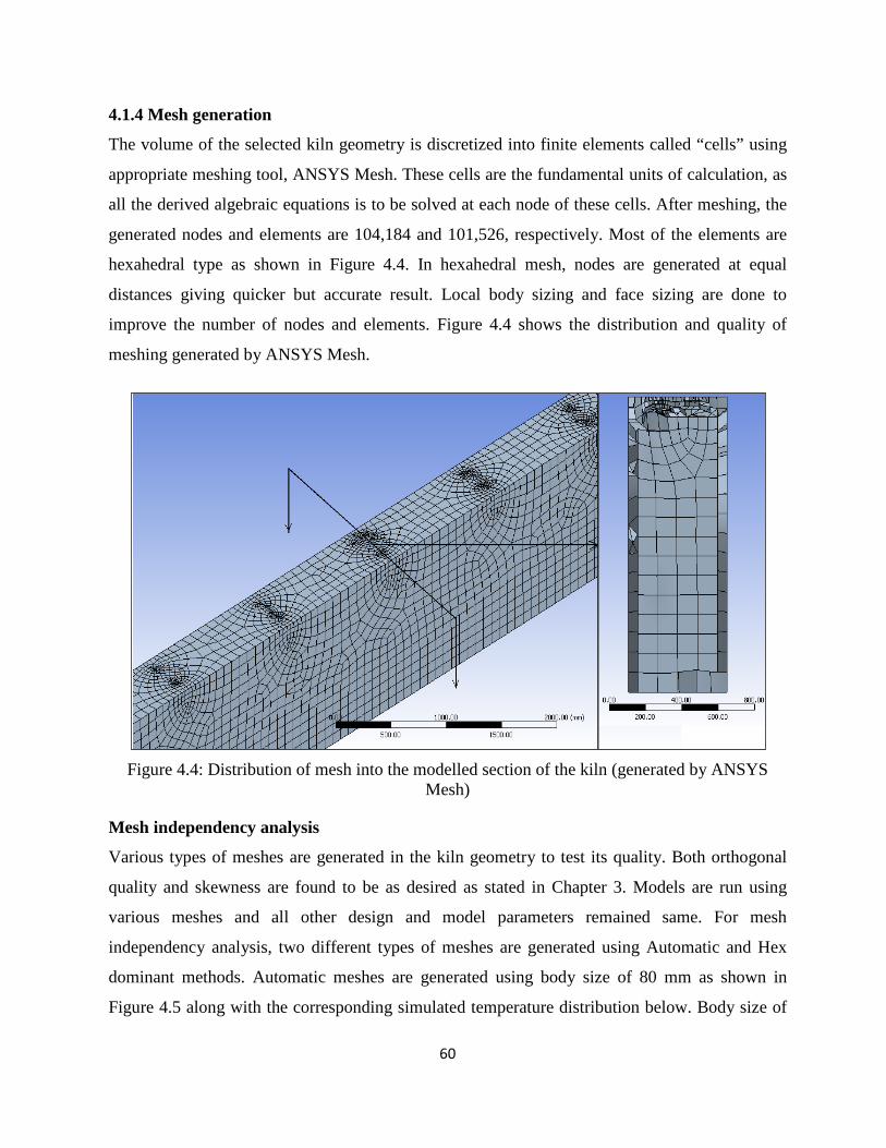
60
4.1.4 Mesh generation
The volume of the selected kiln geometry is discretized into finite elements called “cells” using
appropriate meshing tool, ANSYS Mesh. These cells are the fundamental units of calculation, as
all the derived algebraic equations is to be solved at each node of these cells. After meshing, the
generated nodes and elements are 104,184 and 101,526, respectively. Most of the elements are
hexahedral type as shown in Figure 4.4. In hexahedral mesh, nodes are generated at equal
distances giving quicker but accurate result. Local body sizing and face sizing are done to
improve the number of nodes and elements. Figure 4.4 shows the distribution and quality of
meshing generated by ANSYS Mesh.
Figure 4.4: Distribution of mesh into the modelled section of the kiln (generated by ANSYS
Mesh)
Mesh independency analysis
Various types of meshes are generated in the kiln geometry to test its quality. Both orthogonal
quality and skewness are found to be as desired as stated in Chapter 3. Models are run using
various meshes and all other design and model parameters remained same. For mesh
independency analysis, two different types of meshes are generated using Automatic and Hex
dominant methods. Automatic meshes are generated using body size of 80 mm as shown in
Figure 4.5 along with the corresponding simulated temperature distribution below. Body size of

61
80 mm means the distance between nodes generated in the geometry is roughly around 80 mm
apart. In this method any type of mesh can be generated according to the shape of the geometry.
Advanced size function selects ‘Proximity and Curvature’ and Relevance Centre selects ‘Coarse’
Figure 4.5: Automatic mesh using body sizing 80 mm (333,867 and 1,416,265 nodes and
elements) and corresponding simulated temperature distribution curve
to generate around 333,867 and 1,416,265 nodes and elements respectively. On the other hand
Hex dominant method is used to generate mesh as shown in Figure 4.6 where 100 mm body
sizing is used for meshing. Face sizing of 80 mm in selected faces are also chosen. Nodes and
elements generated using this method are around 106,406 and 105,208 respectively which is
much lower than the Automatic method. However, the results on simulated temperature

62
distributions obtained from these two different simulations as shown in Figures 4.5 and 4.6 are
found to be very much similar except in few places with bumps. Hence mesh independency of
the two modelled geometry is clearly visible.
Figure 4.6: Hex dominant mesh using body sizing 100 mm (106,406 and 105,208 nodes and
elements) and corresponding simulated temperature distribution curve
4.1.5 Simulation parameters and boundary conditions
After generating the meshes in ANSYS Mesh, all the boundary conditions have to be defined
using CFX Pre. To start the simulation, the velocities of the fuel (gas) and air entering into the
kiln are required to model the process. Gas and air inlet temperatures need to be defined at the
beginning; mass fractions of different components of gas and air need to be provided at the start
63
of the simulation. It is assumed that the supplied air is consisted of 23.2% oxygen and rest is
nitrogen. These proportions of oxygen and nitrogen can be considered for the reactions inside the
model domain. Combustion models require a small fraction of reaction products (CO2 and H2O)
to be given at the inlet to initiate combustion simulation. Hence, 0.01 mass fractions of CO2 and
H2O are required at the inlet for proper starting of the reaction simulation (ANSYS 2009).
The default boundary for any undefined surface in CFX-Pre is considered as no-slip, smooth,
adiabatic wall. The walls of the kiln are also assumed to be adiabatic. It is considered that gas
nozzle opening is in the same plane as the kiln roof. For radiation purpose, the wall is assumed to
be perfectly absorbing and emitting surface (emissivity = 1). The kiln wall is non-catalytic,
which means, it is not taking part in the chemical reaction. Probable temperatures of the different
brick stacks are also defined to initiate the model simulation. Brick stack near the entry has lower
temperature and as it moves near the firing zone, the temperature increases. Opposite trend is
shown as the brick stack moves from firing zone to the exit. Heat transfer coefficient for the
brick stack is given as 10 W/m2K as identified in Meng (2011). Gas inlet temperature is assigned
as 150oC. The velocity of incoming gas is given as 6 m/s. Air inlet velocity is taken as around
0.83 m/s at an angle of 14o. It is to be noted here that these values on air and gas velocities are
obtained after several trial runs.
4.1.6 Turbulence, radiation, combustion and NO models
The models that have been applied for the simulation of the brick kiln are: Turbulence model
(Standard ε−k ), Radiation model (P-1), and Combustion model (Flamelet). As high temperature
combustion occurs inside the Tunnel kiln, turbulence is generated. To simulate this turbulence
properly Turbulence model is necessary. Combustion model is added to simulate the generation
of CO2. Separate NO model has to be added to simulate the generation of NO emission. As high
temperature is generated inside the kiln, radiation heat transfer also becomes significant; hence a
Radiation model is also incorporated as mentioned above.
The Standard ε−k model in CFX is one of the simplest complete models of turbulence, in which
the solution of the transport equations are independently determined (Chacon et al. 2007).
Radiative heat transfer is included because the radiant heat flux is high and should be considered
along with convection and conduction considered in Combustion model. CFX includes
Combustion models to allow the simulation of flows in which combustion reactions occur. The

64
Flamelet was developed for use in a wide range of turbulent reaction flows. Because of its
simplicity and robust performance in predicting turbulent reaction flows, this model has been
widely applied in the prediction of industrial flames (Chacon et.al 2007). In CFX, the NO model
is solved in a separate equation. To model NO, the reaction scheme Methane Air WD1 NO PDF
is selected. This introduces NO as an additional component and adds reactions for Thermal and
Prompt NO models (ANSYS 2009).
4.2 Simulation using ANSYS CFX In order to initiate a CFD simulation in brick kiln, the assumptions made for the model are that
the process is under steady-state condition - the temperature at any point remains constant with
time. Due to symmetry assumption, all the strips can replicate this modelled strip and thus can
provide idea of the entire Tunnel kiln geometry.
The simulation is run for steady-state condition, where convergence criterion with RMS (root
mean square) value is taken as 10-4. A suite of trial and error runs show that 600 iterations are
adequate to obtain a fairly stable solution. However it is imperative that, if more iteration is
given the result would marginally improve. From CFX-Post, temperature profile as well as CO2
and NO emission profiles are obtained. Temperature distribution and simulated temperature
distribution curve generated are shown in Figures 4.7 and 4.8. Figure 4.7 shows the temperature
distribution inside the Tunnel kiln when gas velocity is 6 m/s (gas flow rate 0.071 m3/s). Figure
4.8 on simulated temperature distribution matches closely with the Tunnel kiln curve obtained
from industry and literature (Durakovic et al. 2006; Oba et al. 2011; Atanasov et al. 2007), which
indicates that simulation has progressed in the right direction. It is to be noted that the simulation
showed in Figures 4.7 and 4.8 are based on 400 mm spacing between brick stacks and the gas
and air inlet-outlets positions are in between these two brick stacks. However some
modifications on model geometry and design parameters are carried out to improve the
performance of the Tunnel kiln further.
Figure 4.7 clearly distinguishes the firing, cooling and pre-heating zones. The highest
temperature generated is found to be about 1050oC in the firing zone and the lowest temperature
is 50oC at the exit of the finished brick. Figure 4.9 shows the high CO2 concentration after the
firing zone, which moves right and upward due to overall flow direction and temperature rise.
This heated flow increases the brick temperature to attain a maximum temperature of 1050oC and

65
continue steadily for a while in the downward direction. The mass fraction (i.e. ratio between
mass of the gas to the total mass of the gases inside the kiln) of CO2 generated near the firing
zone ranges from 0.05 to 0.174 which when estimated for the whole volume of the kiln strip, a
rate of 1.01 m3/s flow is generated inside the strip. Simulated concentration of NO is also shown
in Figure 4.10. The mass fraction of NO generated inside the kiln near the firing zone is in the
range of 0.005 to 0.01 which when similarly estimated for the whole volume of the kiln strip, a
rate of 0.108 m3/s flow is generated inside the strip. As the volume of CO2 generated inside the
kiln largely depends on the highest temperature reached by the kiln, the theoretical calculation of
CO2 generated can also be included here to give a better picture on emission. Theoretically 0.028
kg/s CO2 is generated inside the kiln strip for 0.071 m3/s gas flow rate. The amount of CO2
generated per 100,000 bricks is 26.22 tCO2e as calculated in Appendix A.
Figure 4.7: Temperature distribution inside the brick kiln (sectional view)
Figure 4.8: Temperature distribution inside the brick kiln for 6 m/s gas velocity (gas flow rate
0.071 m3/s)

66
Figure 4.9: CO2 concentration distribution inside the brick kiln
Figure 4.10: NO concentration distribution inside the brick kiln
The simulated gaseous velocity vectors inside the tunnel are also identified in Figures 4.11, 4.12
and 4.13 at cooling, firing and preheating zones respectively. In the cooling zone, velocity vector
shows entry of cooling air at 14o angle inside the kiln where some of this air after extracting heat
from the brick stack is flown to the dryer through intermediate air outlet. Gaseous velocity near
the firing zone is very high due to combustion as shown in Figure 4.12. After the combustion, as
the temperature gradually decreases towards the preheating zone, air velocity reduces as a
consequence and finally flows out through the flue gas outlet as shown in Figure 4.13.
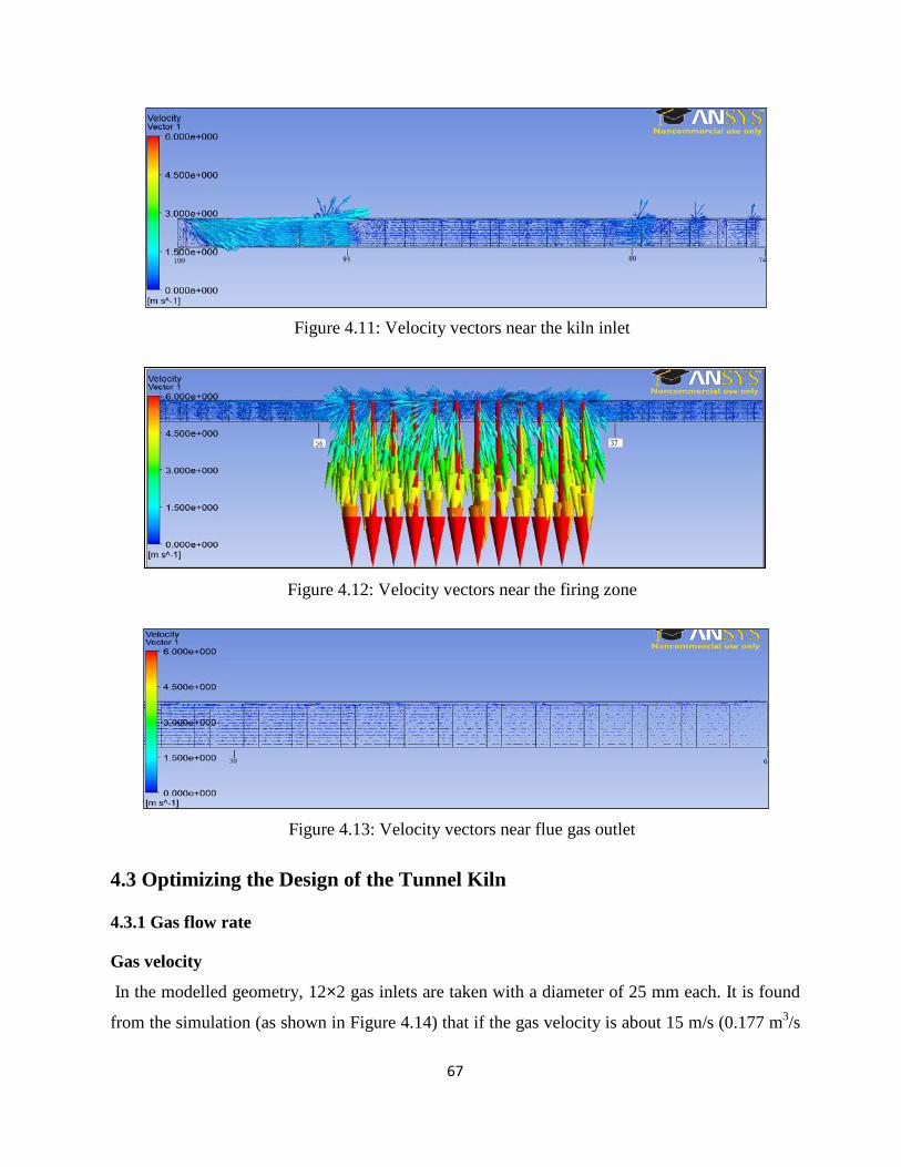
67
Figure 4.11: Velocity vectors near the kiln inlet
Figure 4.12: Velocity vectors near the firing zone
Figure 4.13: Velocity vectors near flue gas outlet
4.3 Optimizing the Design of the Tunnel Kiln
4.3.1 Gas flow rate
Gas velocity
In the modelled geometry, 12×2 gas inlets are taken with a diameter of 25 mm each. It is found
from the simulation (as shown in Figure 4.14) that if the gas velocity is about 15 m/s (0.177 m3/s

68
gas flow rate) it causes gas to accumulate on two sides of the firing zone, as a result temperature
rise is much higher at the end of preheating zone and at the beginning of cooling zone and
relatively less temperature in firing zone. It is clear from the simulation that the temperature
distribution is not matching the industrial Tunnel kiln curve. However if the gas velocity is kept
on decreasing, it shows that at 6 m/s velocity the simulated temperature distribution (as shown in
Figure 4.8) matches closely to the industrial Tunnel kiln curve. To have a good idea on simulated
temperature distributions at 5 m/s and 4 m/s are also shown in Figures 4.15 and 4.16
respectively.
Figure 4.14: Temperature distribution generated for 15 m/s gas flow velocity (0.177 m3/s gas
flow rate)
Reducing gas velocity to 5 m/s (0.059 m3/s gas flow rate) as shown in Figure 4.15 exhibits that
temperature distribution is becoming steeper than desired in the preheating and cooling zone.
And in the firing zone, the temperature suddenly peaks and then drops quickly instead of
remaining stable for a considerable distance. Gas velocity of 4 m/s (0.047 m3/s gas flow rate) as
shown in Figure 4.16 also shows similar trend. From this analysis, the optimum gas velocity is
found to be 6 m/s. However, it is to be noted that there is marginal difference exists for
temperature distribution between the gas velocities 5 m/s and 6 m/s. If the gas velocity is 5 m/s
then the curve shape still remains acceptable, however the curve remains in the high temperature
zone for a short distance as the temperature rises and then falls quickly. So, quality of bricks
produced using this temperature distribution is be slightly inferior. However, energy

69
consumption and emission are going to reduce as the gas flow rate reduces. So if slight quality
deterioration is acceptable then gas inlet velocity of 5 m/s can also be a better choice. However
for all other analysis of this research, the optimum gas velocity is considered 6 m/s. Reduction of
gas velocity means less fuel flow rate and as a result less carbon-di-oxide to generate.
Theoretically 0.0238 kg/s and 0.019 kg/s CO2 is generated inside the kiln for the respective flow
rates.
Figure 4.15: Temperature distribution generated for 5 m/s gas flow velocity (0.059 m3/s gas
flow rate)
Figure 4.16: Temperature distribution for 4 m/s gas flow velocity (0.047 m3/s gas flow rate)

70
Gas inlet diameter
A comparable trend is seen if the gas velocity remains constant and the diameter of the gas inlet
is changed. Reduction of the inlet diameter causes reduced flow rate, which generates a peak
temperature of around 1200oC to produce even steeper curve in preheating and cooling zones
than desired. The curve becomes steeper as it quickly reaches the peak and then falls quickly as
shown in Figures 4.17 and 4.18 for 15 mm (gas flow rate of 0.025 m3/s) and 10 mm (gas flow
rate of 0.011 m3/s) diameters respectively at 6 m/s velocity. Reduction of gas inlet diameter also
causes less CO2 productions as less fuel is burnt. For these two cases, theoretical CO2 generated
is 0.01 kg/s and 0.0044 kg/s respectively.
If the gas flow rate remains constant at 0.071 m3/s and the corresponding velocity is increased to
16.51 m/s and 37.69 m/s for reduced diameters of 15 mm and 10 mm respectively, it generates
again steeper temperature distribution curves (as shown in Figures 4.19 and 4.20) compared to 6
m/s velocity with 25 mm diameter inlet design.
The graphs clearly show that when the gas inlet diameters are reduced gradually (velocity 6 m/s),
flow becomes concentrated while taking part in the reaction and thus increase the peak
temperature. However the spread of the high temperature zone reduces, i.e. temperature
distribution becomes steeper on two sides. Again when the gas inlet diameter is reduced but the
velocity is increased to maintain constant flow rate (0.071 m3/s) then the peak temperature also
increases while the spread of the high temperature zones remain less steep than the previous case
of reduced diameter and constant velocity. Here it is a matter of balance between the choice of
diameter and velocity of gas. It is obvious that while the velocity is 6 m/s with a inlet diameter of
25 mm the resultant simulated temperature distribution is closer to the industrial Tunnel kiln
curve.

71
Figure 4.17: Temperature distribution generated of gas inlet diameter 15 mm (flow rate 0.025
m3/s)
Figure 4.18: Temperature distribution generated of gas inlet diameter 10 mm (flow rate 0.011
m3/s)

72
Figure 4.19: Temperature distribution generated of gas inlet diameter 15 mm (flow rate 0.071 m3/s)
Figure 4.20: Temperature distribution generated of gas inlet diameter 10 mm (flow rate 0.071
m3/s)
4.3.2 Gas velocity direction
In previous simulations, gas velocity direction was vertically downward through the gas nozzles.
So after entering the kiln, gas hits the kiln bottom or brick stacks and then dispersed in both
longitudinal directions as shown in Figure 4.21. Velocity vectors as shown in Figure 4.22
presents that some hot gaseous flow from the combustion zone is moving opposite to the

73
intended flow direction (towards flue gas outlet) and reaching as far as the small air outlets and
passes to the dryer. This phenomenon is not desirable as CO2 and other flue gases generated
should be flowing towards the flue gas outlet where a purifier is usually attached. The purpose of
this purifier is to remove particulate emissions before releasing through the flue gas outlet into
the atmosphere.
Figure 4.21: Gaseous velocity vectors near the firing zone in vertical planes
Figure 4.22: Gaseous velocity vectors near the firing zone in horizontal planes

74
To minimize the effect of backflow of hot gas flow in the firing zone, gas burners are placed at
an angle so the gas enters the firing zone at 45o. Inclined 45o gas flow inside the firing chamber
may drive the hot gas towards the flue gas outlet instead of small air outlets in the opposite
direction. As shown in Figure 4.23, gas inlet is placed at an angle so that gas and air flows are
only diverted towards the flue gas outlet direction. Though backflow of the hot gas towards the
small air outlet could not be totally stopped, however this change ensures a small quantity hot
gas flowing in the opposite direction towards the small air outlet. Figure 4.23 is the gas flow
direction at 45o while inlet velocity of the two left-side gas inlets are reduced to 1 m/s which
shows significantly less hot gas flow in the direction of small air outlets as shown in Figure 4.24
compared to Figures 4.21 and 4.22.
Figure 4.23: Gas flow in the firing zone at 45o angle
Figure 4.24: Hot gas flow direction near small air outlets when gas inflow direction is at 45o
angle
The temperature distribution curve for gas inlet at an angle of 45o in Figure 4.25 shows some
fluctuations in the preheating zone. Gas entering the firing zone creates accumulation of more
hot gases in the preheating zone, resulting into temperature spike in the temperature profile.
Other angles between 90o and 45o are also tried and it is found that in all the cases some spikes
remain visible and it is never possible to reduce the backflow of hot gases completely. So the
direction of gas flow could be kept normal to the kiln roof and some backflow of hot gases
towards small air outlets has to be accepted.

75
Figure 4.25: Temperature spike in preheating zone generated due to gas flow angle at 45°
4.3.3 Air velocity
At the exit end of the finished brick, air entry direction was perpendicular to the kiln roof.
Simulated result clearly showed in Figure 4.26 that backflow of air through the same inlet was
significant which was due to direct hitting of the air to the brick stack.
Figure 4.26: Velocity vectors when air flow direction through large air inlet is normal to kiln
roof
To reduce this backflow, different angles of airflows are applied. Figure 4.27 shows airflow
direction at 14o with respect to the kiln roof. This airflow angle showed better performance as no
backflow is visible through large air inlet. Immediately after the entry, uniform flow is visible
through the kiln with some heated air coming out through the intermediate air outlet due to

76
natural convection. This heated air is transferred to dryer to reduce the moisture of the green
bricks. The amount of heated air coming out of intermediate air outlet and small air outlets are
Figure 4.27: Air flow direction in vertical and horizontal planes near large air inlet and
intermediate air outlet
simulated to be about 6.83 kJ/s as calculated in Eq A.1 of Appendix A. However after reaching
the firing zone due to addition of combustible gas, fluid flow velocity increased significantly in
the region as shown in Figure 4.28. Eventually flow velocity again decreased at the entry of the
green bricks near to the flue gas outlet as shown in Figure 4.29.

77
Figure 4.28 Gaseous flow directions near firing zone
Figure 4.29: Gaseous flow direction in vertical and horizontal planes near flue gas outlet

78
4.3.4 Gaps between brick stack and kiln roof
50 mm gap
When the gap between the top of the brick stack and the roof is reduced to 50 mm, bricks placed
on the upper portion of the stack face more temperature fluctuation due to the incoming cooling
air. As a result of this fluctuation, necessary structural change may be hampered and cracks may
be formed (Personal Communication 2012). The evidence of this fluctuation is presented in
Figure 4.30. From this analysis, it can be concluded that, increasing the brick stack height or
reducing the gap between the stack and kiln roof increases temperature fluctuation. This may
eventually deteriorate the uniform quality of the bricks on the top of the stack.
Figure 4.30: Temperature distribution when gap between the top of the brick stack and the roof is
reduced to 50 mm
50 mm

79
200 mm gap
Increasing the gap between the brick stack and the kiln roof to 200 mm shows less temperature
fluctuation compared to the gap of 50 mm as shown in Figure 4.31. The fluctuation is even less
compared to the earlier 100 mm gap as shown in Figure 4.8.
Figure 4.31: Temperature distribution when gap between the top of the brick stack and the roof is
increased to 200 mm
From the comparison, it can be said that, if the brick stack gap is doubled from 100 mm to 200
mm, it generates a better Tunnel kiln curve so ensures quality brick production. However, the
gap between kiln roof and the brick stack is not increased further because some of the initial
simulations showed that if the gap between brick stack and the kiln roof is too large, then
200 mm
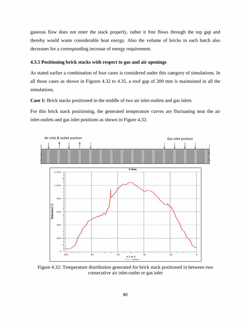
80
gaseous flow does not enter the stack properly, rather it free flows through the top gap and
thereby would waste considerable heat energy. Also the volume of bricks in each batch also
decreases for a corresponding increase of energy requirement.
4.3.5 Positioning brick stacks with respect to gas and air openings
As stated earlier a combination of four cases is considered under this category of simulations. In
all those cases as shown in Figures 4.32 to 4.35, a roof gap of 200 mm is maintained in all the
simulations.
Case 1: Brick stacks positioned in the middle of two air inlet-outlets and gas inlets
For this brick stack positioning, the generated temperature curves are fluctuating near the air
inlet-outlets and gas inlet positions as shown in Figure 4.32.
Figure 4.32: Temperature distribution generated for brick stack positioned in between two
consecutive air inlet-outlet or gas inlet
Air inlet & outlet position Gas inlet position

81
Case 2: Brick stacks positioned in the middle of two air inlet-outlets and directly below the gas
inlets
For this case the temperature curve shows relatively smooth change in the gas inlet position,
while some fluctuations are visible in the air inlet and outlet positions as shown in Figure 4.33.
So, a decision can be drawn that, if brick stacks are positioned directly below the gas inlet then a
smooth curve can be obtained near gas inlet region. Smooth curve ensures less temperature
fluctuations and thus uniform quality bricks.
Figure 4.33: Temperature distribution generated for brick stack positioned in the middle of two
air inlet-outlets and directly below the gas inlets
Case 3: Brick stacks positioned just below air inlet-outlets or in between two gas inlets
For this case the temperature curve shows relatively smooth change in the air inlet-outlet
positions however some fluctuation in the gas inlet positions as shown in Figure 4.34. Though
slight fluctuations is not going to cause huge quality difference however, smooth curve may
Air inlet & outlet position Gas inlet position

82
ensure good quality bricks. So, a decision can be drawn that, if brick stacks are positioned
directly below the air inlet-outlets then a smooth curve can be obtained near the air inlet-outlet
region.
Figure 4.34: Temperature distribution generated for brick stack positioned directly below the air
inlet-outlets and in between two gas inlets
Case 4: Brick stacks positioned directly below air inlet-outlets or gas inlets
Finally, for this case the temperature distribution curve shows relatively smooth change near the
air inlet-outlet positions and gas inlet positions as shown in Figure 4.35. Thus, conclusion can be
drawn that this Case 4 is the most suitable brick stack positioning configuration to manufacture
uniform quality bricks.
Gas inlet position Air inlet & outlet position

83
Figure 4.35: Temperature distribution generated for brick stacks positioned directly below
air inlet-outlets and gas inlets
4.3.6 Gap between brick stacks
Brick stacks gap reduced to 300 mm and stack length increased to 1020 mm
Gap reduction between two brick stacks ensures higher brick production as more bricks can be
accommodated at a given batch inside the kiln. In Figure 4.36, the gap between the stacks is
reduced to 300 mm and as a consequence the stack length has increased to 1020 mm. The
generated temperature distribution curve with this configuration shows a smooth pattern.
Air inlet & outlet position Gas inlet position

84
Figure 4.36: Gap between two brick stacks reduced to 300 mm
Brick stacks gap reduced to 200 mm and stack length increased to 1120 mm
Further decrease of brick stack gaps to 200 mm and consequently increase of brick stack lengths
to 1120 mm more or less retains the smoothness of temperature distribution of the previous case
as shown in Figure 4.37. Without increasing the brick stack size, the gaps between the brick
stacks could be reduced to increase the number of brick stacks beyond 75. Increasing the brick
stack size or the stack number increases the brick production by accommodating more bricks at
the same batch inside the kiln. However, the fuel usage remains the same and thus the production
becomes more fuel efficient. A further reduction of gaps showed increased fluctuation in the
temperature distribution curve because small air inlet-outlet diameters are taken 250 mm, so a
further reduction in the stack gap is not bound to bring better result. So there should be a balance
between gap and quality of the brick production.
300 mm 1020 mm

85
Figure 4.37: Gap between two brick stacks reduced to 200 mm
From this simulation, it can be concluded that, brick stack gaps could be reduced to 200 mm.
However, stack width may remain same. In that way the number of brick stacks is going to be
increased. More bricks can be produced with the same amount of fuel and thus the efficiency of
the kiln can be improved.
4.3.7 Efficient geometric model prediction from simulation
From all the simulations above, optimum gas velocity is found to be 6 m/s with gas inlet
diameter of 25 mm to produce a desired temperature distribution matching the industrial Tunnel
kiln curve. Backflow of hot gas in the opposite direction of intended flow is a problem. This
problem is tried to be solved by placing the gas inlet at an angle of 45o. Even though the
backward flow of hot gas is reduced as an effect of this angled flow, the fluctuation in the
generated temperature distribution curve has increased. So, for the sake of producing better
temperature distribution curve, backflow of a portion of the hot gas has been taken acceptable.
200 mm 1120 mm

86
From the simulation it is found that 200 mm gap between brick stacks and kiln roof ensures
better temperature distribution along the kiln length. So the gap between brick stacks and kiln
roof can be increased to 200 mm compared to 100 mm as initial guess. If brick stacks are
positioned just below air inlet-outlets or gas inlets then temperature distribution curve achieves
desired characteristics better. Reducing the gaps between brick stacks produces better
temperature distribution curve. The gaps between the brick stacks can be reduced to 200 mm.
However, the length of the brick stacks may remain 920 mm. As a result, more brick stacks can
be accommodated at a given batch inside the brick kiln. This is going to ensure higher brick
production for the same fuel consumption. The Tunnel kiln dimensions as optimized through all
the above systematic runs of the model can be shown in Figure 4.38. To show the impact of all
those designed parameters are summarized in Table 4.1 for easy comparison.
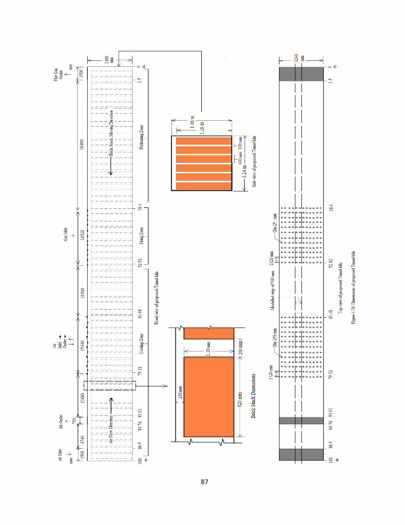
87
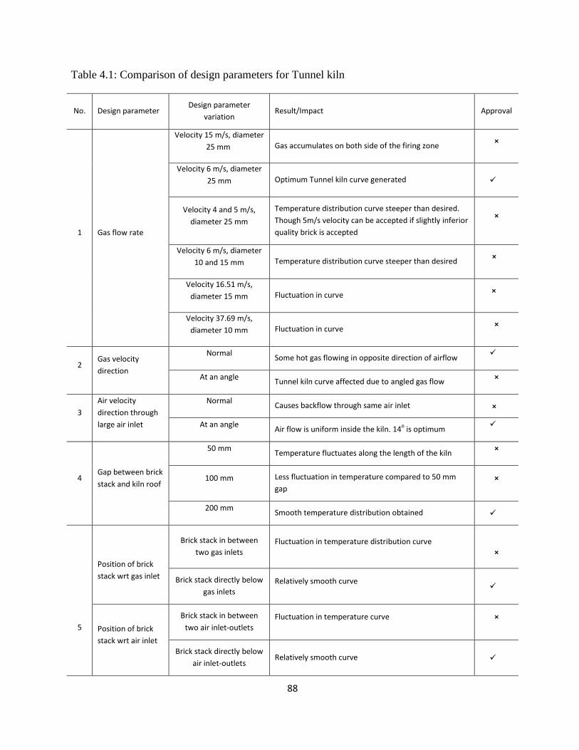
88
Table 4.1: Comparison of design parameters for Tunnel kiln
No. Design parameter Design parameter
variation Result/Impact Approval
1 Gas flow rate
Velocity 15 m/s, diameter 25 mm Gas accumulates on both side of the firing zone ×
Velocity 6 m/s, diameter 25 mm Optimum Tunnel kiln curve generated
Velocity 4 and 5 m/s, diameter 25 mm
Temperature distribution curve steeper than desired. Though 5m/s velocity can be accepted if slightly inferior quality brick is accepted
×
Velocity 6 m/s, diameter 10 and 15 mm Temperature distribution curve steeper than desired ×
Velocity 16.51 m/s, diameter 15 mm Fluctuation in curve ×
Velocity 37.69 m/s, diameter 10 mm Fluctuation in curve ×
2 Gas velocity direction
Normal Some hot gas flowing in opposite direction of airflow
At an angle Tunnel kiln curve affected due to angled gas flow ×
3 Air velocity direction through large air inlet
Normal Causes backflow through same air inlet ×
At an angle Air flow is uniform inside the kiln. 14o is optimum
4 Gap between brick stack and kiln roof
50 mm Temperature fluctuates along the length of the kiln ×
100 mm Less fluctuation in temperature compared to 50 mm gap
×
200 mm Smooth temperature distribution obtained
5
Position of brick stack wrt gas inlet
Brick stack in between two gas inlets
Fluctuation in temperature distribution curve
×
Brick stack directly below gas inlets
Relatively smooth curve
Position of brick stack wrt air inlet
Brick stack in between two air inlet-outlets
Fluctuation in temperature curve ×
Brick stack directly below air inlet-outlets
Relatively smooth curve

89
6 Gap between two brick stacks
400 mm Proper temperature distribution curve generated ×
300 mm Curve smoother and better than 400 mm gap ×
200 mm Better curve obtained, higher number of brick production so increased fuel efficiency
4.4 Summary For simulation purpose, the geometry of a typical Tunnel kiln is drawn using ANSYS Design
Modeller. Due to symmetry, one-sixth of the width (540 mm) along the entire length (100 m) of
the kiln is considered adequate for simulation. The volume of the selected kiln geometry is
discretized using ANSYS Mesh. Boundary conditions are defined using CFX Pre. Mesh
independency analysis is conducted using two meshing methods and is found to be ‘mesh
independent’. Proper models for turbulence, combustion and radiation are selected and the
simulation is run under steady-state condition.
If the gas velocity is more than 6 m/s, it causes gas to accumulate on both sides of the firing
zone. Gas velocity of 6 m/s with gas inlet diameter of 25 mm generates a better temperature
distribution curve to match industrial Tunnel kiln curve. Keeping the gas velocity constant and
reducing the gas inlet diameter as well as keeping gas inlet diameter constant and reducing the
gas velocity, generates steeper temperature distribution curves as gas flow rate has been reduced
in both the cases. Gas inlet velocity of 5 m/s with 25 mm gas inlet diameter can also be accepted
if slightly inferior quality bricks are accepted. If the quality of the outputs from the Tunnel kiln is
slightly compromised then the fuel consumption is going to be significantly reduce and thus is
going to reduce emission further. It is found from the simulation that, lower gas inflow into the
combustion chamber results less emission. So, reducing gas flow rate is going to reduce CO2 and
NO production. So, the modified design may ensure less pollution.
To reduce hot gas flow in the opposite direction of the intended airflow, attempts are made to
place the gas inlet direction at an angle. However, this initiative affects the generation of
temperature distribution curve and thus not considered for further simulation. Gas inflow
direction is thus kept normal to kiln roof. Reduction of the gap between brick stacks and kiln
roof causes more fluctuation in temperature distribution to impact uniform burning of the bricks.
On the other hand if air flow direction from the large air inlet is normal to the kiln roof then due

90
to direct strike on brick stack or kiln bottom, some backflow is inevitable. Air inflow at an angle
of 14o to kiln roof ensures uniform flow through the kiln.
The optimum gap between brick stacks and kiln roof is thus taken to be 200 mm. If brick stacks
are placed in between two air inlet-outlets and/or gas inlets then the temperature curve becomes
fluctuating. However, if brick stacks are positioned directly below the air inlet-outlets and gas
inlets, relatively smooth temperature distribution can be obtained and thus adopted as optimum
design parameter. Reduction of the gap between brick stacks ensures higher brick production as
more bricks can be accommodated at the same batch inside the kiln. If the gap between the
stacks is reduced to 200 mm, it retains the smoothness of the curve.

91
Chapter 5
Conclusion and Recommendation
5.1 Conclusion
This study demonstrated that CFD can be used as an effective tool for analysis and design for
brick burning application. The CFD simulations are being used to increase efficiency and thus
optimize the design and reduce emissions of combustion by replacing expensive and time
consuming experiments. Commercially available software ANSYS CFX is used to evaluate
temperature profile and COx and NOx emissions in the system.
After drawing, meshing and simulating the Tunnel kiln geometry, generated temperature
distribution curve from the simulation is verified against Tunnel kiln curve obtained from
industry. Several model runs with changing parameters are carried out systematically to obtain
an idea about best possible performance of a given Tunnel kiln. The resultant best performing
parameters are setting an optimized design in order to improve the performance of the kiln. For
design optimization several simulations are run by altering the design conditions and thereby
simultaneously COx and NOx emissions from various designs are compared and a low emitting
design is obtained.
In the optimized simulation the highest temperature obtained is around 1050oC and the lowest
temperature during the exit of the finished brick is around 50oC. It is found from the simulation
that at gas velocity of 6 m/s through an inlet diameter of 25 mm, the temperature distribution
curve obtained closely matches the industrial Tunnel kiln curve. Gas inlet can be placed at an
angle so that gaseous flow is only directed towards the flue gas outlet and thus backflow of
heated gas can be minimized. However, angled gas flow causes fluctuation in the temperature
distribution curve. So, gas flow direction normal to the kiln roof is found to be more effective. If
the gap between brick stack and kiln roof is increased to 200 mm, the temperature fluctuation in
the Tunnel kiln curve is reduced compared to the initial gap of 100 mm. Hence, a gap of 200 mm
between brick stacks and kiln roof is proposed for modified design. If brick stacks are placed just
below the air inlet-outlets and gas inlets, then better temperature distribution curve is obtained.

92
Suggestions are made to reduce the gap between brick stacks to 200 mm from the initial 400 mm
gaps, without increasing the brick stack size but by increasing the number of brick stacks. As a
result a further smoother temperature distribution is obtained. This particular arrangement is
going to increase the brick production with the same amount of fuel consumed and thus make the
production more fuel efficient. Larger inlet air flow direction is set to 14o to ensure uniform
gaseous flow through the kiln towards flue gas outlet.
It is found from the simulation that lesser gas inflow in the combustion chamber results less CO2
and NO generation. So, reducing the gas inlet velocity or gas inlet diameter can definitely reduce
CO2 and NO production. So, the modified design ensures less pollution. The amount of CO2
generated per 100,000 bricks from the proposed Tunnel kiln design is 26.22 tCO2e. Though this
amount is equivalent to the low efficiency kilns as found from Chapter 5, however, it is to be
noted that the quality of bricks generated from the Tunnel kiln is far superior compared to the
bricks produced in those inefficient kilns. Bricks produced from Tunnel kilns are superior in
strength, color and quality so requires more energy. So, it can be concluded that even same
amount of energy is used in Tunnel kilns however this energy is efficiently utilized to produce
superior quality bricks. If the quality of the outputs from the Tunnel kiln is slightly compromised
then the fuel consumption is going to be significantly reduced and thus can reduce emission
further.
5.2 Recommendation
High concentration of fluoride in clay minerals of Australia have a considerable impact on its
emission (Environment Protection Authority 1999), so fluoride emission simulation can be
incorporated in the future by adding user defined function (UDF) in the model. Only Tunnel kiln
based on gas firing was simulated, however currently in many countries coal fired Tunnel,
Hoffman, Vertical Shaft and Zigzag kilns are in use. CFD simulation can be conducted in those
kilns as well to improve their performances. So coal based kilns can be simulated using ANSYS
CFX to determine comparative emission performances.

93
References Andersson, B, Andersson, R, Hakansson, L, Mortensen, M, Sudiyo, R & Wachem, BV 2012,
Computational Fluid Dynamics for Engineers, Cambridge University Press, New York, USA.
Ai-chun, M, Jie-min, Z, Jian-ping, O & Wang-xing, L 2006, ‘CFD prediction of physical field
for multi-air channel pulverized coal burner in rotary kiln’, Journal CSUT, Vol.13, No.1.
Atanasov, A & Delchev, N 2007, ‘Improved operating conditions at firing of electro-porcelain
insulators in a Tunnel kiln’, Journal of the University of Chemical Technology and Metallurgy,
Vol.42, No.3, pp. 277-280.
ANSYS 2009, ANSYS CFX help file and tutorial, ANSYS Inc, version 13, SAS IP.
BUET 2007, Small study on air quality of impacts of the North Dhaka brickfield cluster by
modelling of emissions and suggestions for mitigation measures including financing models,
Chemical Engineering Department, Bangladesh University of Engineering and Technology
(BUET).
Cengel, Y, Cimbala, J 2010, Fluid mechanics: Fundamentals and Applications, Second Edition,
McGraw Hill, New York.
Chacon , J, Sala, JM & Blanco, JM 2007, ‘Investigation on the design and optimization of a low
NOx-CO emission burner both experimentally and through computational fluid dynamics (CFD)
simulation’ Energy & Fuels, Vol. 21, pp. 42-58.
CDM 2009, Improving kiln efficiency in the brick making industry in Bangladesh, Project Design
Document Form (CDM-SSC-PDD), Clean Development Mechanism, Version 02/17/2009,
World Bank, Washington DC.
Clean Energy Alternatives 2011, Feasibility study of Banalata Refractory Ltd, Dhaka, Submitted
to UNDP, Dhaka, Bangladesh.
CDM 2007, Improving kiln efficiency of the brick making industry in Bangladesh, Project Design
Document Form (CDM-SSC-PDD), Clean Development Mechanism, Date 24-10-2007, Version
02, World Bank, Washington DC.
Chen, Z, Zhang, H & Zhu, Z 1999, An integrated intelligent system for ceramic kilns, Expert
systems with applications, Vol. 16, pp. 55-61.

94
Co, HX, Dung, NT, Le, HA, An, DD, Chinh, KV & Oanh, NTK 2009, ‘Integrated management
strategies for brick kiln emission reduction in Vietnam: a case study’, International Journal of
Environment Studies, Vol.66, No.1, pp. 113-124.
DENR 2008, Early bricks and brickworks in South Australia, Department of Environment and
Natural Resources, City of Adelaide, Australia.
DA–PA 2010, Introduction of vertical shaft brick kiln in Bangladesh, CASE Project for Energy
Sector Management Assistance Program (ESMAP),World Bank, Final Project Report by
Development Alternatives - Practical Action (DA-PA).
Durakovic, J & Delalic, S 2006, ‘Temperature field analysis of Tunnel kiln for brick production’,
Journal of Materials and Geo-environment, Vol.53, No.3, pp. 403-408.
Energy Efficiency Opportunities 2007, Industrial case study- Midland bricks, Commonwealth of
Australia.
Environment Australia 1998, Emissions estimation technique manual for bricks, ceramics and
clay product manufacturing, National Pollutant Inventory, Australia.
Environment Protection Authority 1998, Environmental guidelines for the fired clay building
products industry, State Government of Victoria, Australia.
Feedback Ventures 2010, Detailed project report on technology upgradation from straight line
to zigzag firing, Bureau of Energy Efficiency, Ministry of Power, Government of India.
Frontier Economics 2011, Carbon price modelling, A report prepared for NSW government,
http://www.treasury.nsw.gov.au/__data/assets/pdf_file/0017/20465/Carbon_Price_Impacts_Front
ier_report_NSW_Gov_FINAL_Aug_11.pdf.
Garcia, CA, Sanchez, F & Pirajan, CM 2006, ‘Simulation and flow analysis for a brick furnace’,
Electronic Journal of Environmental, Agricultural and Food Chemistry, Vol. 5, pp.1500-1508.
Greentech Knowledge Solutions 2012, Brick kilns performance assessment & a roadmap for
cleaner brick production in India, Sakti sustainable energy foundation and climate works
foundation.
Habla Zigzag kiln 2011, Habla zigazag kiln technology information memorandum, Habla kilns
Pty Ltd.
95
Hammond, GP & Jones CI 2008, Inventory of carbon & Energy (ICE), Sustainable energy
research team, Department of Mechanical Engineering, University of Bath, UK.
Hauck 2005, Optimizing burner placement, Elster Group.
IIDFC 2009, Improving kiln efficiency in the brick making industry in Bangladesh, Hybrid
Hoffman kiln project, Environmental Management Framework P.41, Industrial and Infrastructure
Development Finance Company (IIDFC).
Jamaleddine, TJ & Ray, MB 2010, ‘Application of computational fluid dynamics for simulation
of drying process: A Review’, Drying Technology: An International Journal, Taylor and Francis,
Vol.28, pp.120-154.
Kaya, S, Kurtul, K & Mancuhan, E 2007, ‘Modelling and optimization of heat recovery in the
cooling zone of a Tunnel kiln’, Applied Thermal Engineering, Taylor and Francis, Vol.28,
pp.633-641.
Kaya, S, Kucukada, K & Mancuhan, E 2008, ‘Model-based optimization of heat recovery in the
cooling zone of a Tunnel kiln’, Applied Thermal Engineering, Vol.28, pp.633-641.
Kaya, S, Mancuhan, E & Kurtul, K 2009, ‘Modelling and optimization of firing zone of a Tunnel
kiln to predict the optimal feed locations and mass fluxes of the fuel and secondary air’, Applied
Energy, Vol.86, pp.325-332.
Kelly, A 2011, Clay brick manufacturing in Australia, IBISWorld Industry Report C2621.
Kelly, A 2012, Clay brick manufacturing in Australia, IBISWorld Industry Report C2621.
Kynaston, H 1984, A study of limestone quarrying at Llanymynech, viewed 1 May 2011.
http://www.llanymynech.org.uk/html/hoffman_kiln.html.
Leap Australia 2010, Ansys CFX Training (Including design modeller) Manual, Leap Australia.
Maithel, S, Uma, R, Johri, R, Kumar, A & Vasudevan, N 1999, Energy conservation and
pollution control in brick kilns, Tata Energy Research Institute, New Delhi, India.
Maithel, S, Vasudevan, N, Johri, R & Kumar, A n.d., Pollution reduction and waste
minimization in brick making, Tata Energy Research Institute, New Delhi, India.

96
Mancuhan, E 2009, ‘Analysis and optimization of drying of green bricks in a Tunnel dryer’,
Drying Technology: An International Journal, Taylor and Francis, Vol.27, pp.707-713.
Meng, P 2011, Solid-solid Recuperation to improve the energy of Tunnel kiln, PhD thesis, Otto
von Guericke University, Germany.
NICE 2001, Brick Kiln Design Using Low Thermal-Mass Technology, US Department of
Energy.
Oba, R, Possamai, TS, Nunes, AT & Nicolau, VP 2011, ‘Numerical simulation to Tunnel kilns
applied to white tile with natural gas’, Brazilian Congress of Mechanical Engineering.
Practical Action 2010, Vertical Shaft Brick Kiln (VSBK) – a green technology for red brick
production, Brochure - Practical Action.
Purimetla, A & Cui, J 2009, ‘CFD studies on burner secondary airflow’, Applied mathematical
modelling, Vol.33, pp.1126-1140.
Rasul MG & Saotayanan D 2007, ‘Modelling and simulation of thermodynamic processes of
vertical shaft kiln used for producing dead-burned magnesia’, International Journal of Energy
and Environment, Vol.1, Issue.1.
Sheng, C, Moghtaderi, B, Gupta, R & Wall, TF 2004, ‘A computational fluid dynamics based
study of the combustion characteristics of coal blends in pulverized coal-fired furnace’, Fuel,
Vol.83, pp.1543-1552.
Stuart, I 1987, A history of the Victorian brick industry: 1826-1920, Victoria Archaeological
Survey, Australia.
Stuart, I 1989, Why did the Hoffman brick and pottery works stops making bricks, Victoria
Archaeological Survey, Australia.
Australian Government 2011, Securing a clean energy future, Department of Climate Change
and Energy Efficiency, Australia.
Think Brick Australia 2008, Carbon pollution reduction scheme design, Carbon pollution
reduction scheme green paper submission to Department of climate change, Australia.

97
Tu, J, Yeoh, GH & Liu, C 2013, Computational Fluid Dynamics – a practical approach, Second
Edition, Elsevier, UK.
Vijapurapu, S, Cui, J & Sastry, M 2006, ‘CFD application for coal/air balancing in power
plants’, Applied Mathematical Modelling, Vol.30, pp. 854-866.
World Bank 2011, Introducing Energy-Efficient Clean Technology in the Brick Sector of
Bangladesh, Energy Sector Management Assistance Program, Report No. 60155-BD, June 2011.
World Bank 2011, Improving kiln efficiency in the brick making industry in Bangladesh, Project
design document form, CDM-SSC-PDD, Version 04/03/11, Washington DC.
Wikipedia 2011, Article on clay and bricks, Viewed 10 November 2011.
en.wikipedia.org/wiki/Clay
Yang, Y, Rakhorst, J , Reuter, MA & Voncken, JHL 1999, ‘Analysis of gas flow and mixing in a
rotary kiln waste incinerator’, Second International Conference on CFD in the Minerals and
Processing Industries, CSIRO, Melbourne, Australia.
Yu, B 2007, ‘Dynamic modelling of a Tunnel kiln, Heat Transfer Engineering’, Taylor and
Francis, Vol.15, Issue.2, pp.3

98
Appendix A
1 mol of CH4 generates 1 mol (44 grams) of CO2.
At firing zone temperature and pressure, 1 mol of CH4 has a volume of 0.109 m3 [ V = 𝑅𝑇𝑃
]
From 144 (12×12) gas inlets with 25 mm diameter and a velocity of 6 m/s, total flow rate is 0.42
m3 of CH4. From this amount of methane 0.17 kg/s of CO2 should generate theoretically. So, if
the Tunnel kiln is run for 365 days of a year, the amount of, CO2 generated is 5346 ton.
Volume of total brick stack at a time inside the kiln is 251 m3 (Length 0.92 mm × Width 0.44
mm × Height 1.38 mm × 75 rows × 6 columns). Volume of one brick is 2.25 m-3. Brick numbers
at a time inside the kiln is 111725. If it is assumed that brick stack remains inside the tunnel for 2
days, then total brick numbers burnt inside the kiln for the whole year are 20,389,711. So, the
amount of CO2 generated per 100,000 bricks is 26.22 tCO2e.
At the firing zone temperature and pressure, 0.109 m3 of CH4 generates 44 gram of CO2. So,
0.07 m3 of CH4 generates (.044×.07/0.109) = 0.028 kg/s of CO2
0.059 m3 of CH4 generates (.044×.059/0.109) = 0.0238 kg/s of CO2
0.047 m3 of CH4 generates (.044×.049/0.109) = 0.019 kg/s of CO2
0.025 m3 of CH4 generates (.044×.025/0.109) = 0.01 kg/s of CO2
0.011 m3 of CH4 generates (.044×.011/0.109) = 0.004 kg/s of CO2
Heat energy released from the intermediate air outlet to the dryer can be calculated using the
following formula:
𝑄 = 𝑚.𝐶𝑝.∆𝜃 (A.1)
Here m is found from the simulated result as 0.158 kg/s, 𝐶𝑝 is 1.006 for air and air inlet
temperature is 25oC whereas average temperature at intermediate air is found to be 68oC. So, the
temperature difference ∆𝜃 is 43oC.
So, energy transfer for intermediate air outlet is 6.83 kJ/s.
Calculation for Emission of HK, VSBK, FCK and Zigzag kiln (CDM 2007; Environment
Australia 1998)

99
CFEFQSFCE ×××= (B.5)
where E = emission of CO2 in tCO2e, SFC = specific fuel (energy) consumption in the kiln
(TJ/brick), Q = total number of brick production in question (say, 100,000 bricks), EF = IPCC
default carbon emission factor for the given fuel (in this case, coal) = 25.80 tC/TJ, CF = carbon
to CO2 conversion factor = 3.67 tCO2e/tC (CDM 2007).
The specific fuel (energy) consumption, SFC (TJ/brick) can be calculated as follows:
brick
coalcoalQ
CVQSFC
×= (B.6)
where Q coal = total coal consumption per 100,000 bricks for the given kiln, CV coal = calorific
value of the coal (16,748 KJ/kg coal) (CDM 2007), Q bricks = number of bricks produced
(say,100,000 bricks).
TJ/brick 104.02 KJ/brick 4019.5 000,100
KJ/kg 16,748 kg 000,24 6-×==×
=FCKSFC
TJ/brick 102.35 KJ/brick 2344.7 000,100
KJ/kg 16,748 kg 000,14 6-×==×
=HHKSFC
TJ/brick 101.68 KJ/brick 1674.8 000,100
KJ/kg 16,748 kg 000,10 6-×==×
=VSBKSFC
TJ/brick 103.02 KJ/brick 3014.6 000,100
KJ/kg 16,748 kg 000,18 6-×==×
=ZigzagSFC
Emission of CO2 in tCO2e per 100,000 brick production in each type of kiln
e tCO38.06 e/tC tCO3.67 tC/TJ25.8 bricks 100,000 TJ/brick 1002.4 226 =××××= −
FCKE
e tCO22.20 e/tC tCO3.67 tC/TJ25.8 bricks 100,000 TJ/brick 1035.2 226 =××××= −
HHKE
e tCO15.86 e/tC tCO3.67 tC/TJ25.8 bricks 100,000 TJ/brick 1068.1 226 =××××= −
VSBKE
e tCO28.54 e/tC tCO3.67 tC/TJ25.8 bricks 100,000 TJ/brick 10 3.02 226 =××××= −
ZigZagE

100
Appendix B
Tehzeeb, AH, Bhuiyan, M & Jayasuriya, N, 2012, ‘Evaluation of brick kiln performance using
Computational Fluid Dynamics (CFD)’, Energy and Environmental Engineering Journal,
ASSET, Vol. 1, No. 2, pp. 86-93.
http://www.assetedu.org/uploads/contents/19-content-EEEJ-paper-127.pdf