evaluation of bulk degaussers for secure erasure …evaluation of bulk degaussers for secure erasure...
TRANSCRIPT

Evaluation of Bulk Degaussers for Secure Erasure of Magnetic Media
Presented at the THIC Meeting at the National Center for Atmospheric Research, 1850 Table Mesa Drive, Boulder CO 80305-5602
August 21-22, 2007
Fred Spada
University of California, San DiegoCenter for Magnetic Recording Research
9500 Gilman Drive, La Jolla CA 92093-0401Phone: +1-858-534-8675 FAX: +1-858-534-2720
E-mail: [email protected]

228/21/078/21/07
IntroductionBulk degaussing methods expose entire magnetic storage devices or removable magnetic media cartridges to sufficiently strong AC, DC, or pulsed magnetic fields.
Bulk degaussing methods are preferred and sometimes essential for erasure of magnetic media containing unencrypted data, when large quantities of magnetic storage devices must erased, or when erasure must be performed quickly.
Media containing extremely sensitive data must be secure erased, which is defined as erasure so that the magnetic patterns cannot be recovered or reconstructed by any known means.
Bulk erasure methods satisfy this criterion when the recorded magnetic patterns have been erased to the “media noise” level (i.e., there are no bit patterns remaining for recovery)
338/21/078/21/07
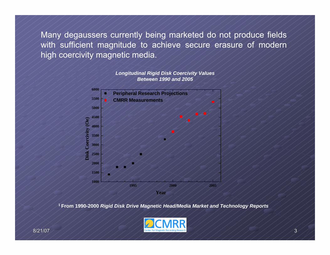
Longitudinal Rigid Disk Coercivity Values Between 1990 and 2005
1 From 1990-2000 Rigid Disk Drive Magnetic Head/Media Market and Technology Reports
Many degaussers currently being marketed do not produce fields with sufficient magnitude to achieve secure erasure of modern high coercivity magnetic media.
1995 2000 20051000
1500
2000
2500
3000
3500
4000
4500
5000
5500
6000
Peripheral Research Projections CMRR Measurements
Dis
k C
oerc
ivity
(Oe)
Year

448/21/078/21/07
The suitability of a bulk degausser for secure erasure of magnetic media depends upon:
- Magnetic properties of the media being erased
- Magnitude, orientation, and distribution of magneticfields within the degaussing chamber
- Physical design characteristics of the degausser that may promote or permit inadvertent improper use (e.g.,placement of media in weak field locations within thedegaussing chamber).

558/21/078/21/07
-10000 -8000 -6000 -4000 -2000 0-1.0x10⁻⁴
-8.0x10⁻⁵
-6.0x10⁻⁵
-4.0x10⁻⁵
-2.0x10⁻⁵
0.0
2.0x10⁻⁵
4.0x10⁻⁵
6.0x10⁻⁵
8.0x10⁻⁵
-2.0x10⁻⁸-1.0x10⁻⁸
0.01.0x10-82.0x10-83.0x10-84.0x10-85.0x10-86.0x10-87.0x10-88.0x10-89.0x10-81.0x10-71.1x10-71.2x10⁻⁷
HcrFWHM= 5330 Oe
Hcrp= 4740 Oe
M (e
mu)
H (Oe)
Hcr= 4670 Oe
dM
/dH
(em
u/O
e)
A. Measure Properties of Magnetic Media
Remanent magnetization behavior and switching field distributiondetermined via:
-VSM, AGM, SQUID (tape and hard disk media; limited tosmall specimen dimensions)
-Polar Kerr Magnetometer (perpendicular disk media; both small specimens and entire disks can be measured)
Experimental Approach

668/21/078/21/071/1
/2000
7/1/20
001/1
/2001
7/1/20
011/1
/2002
7/1/20
021/1
/2003
7/1/20
031/1
/2004
2400
2800
3200
3600
4000
4400
4800
Hc (O
e)
Date on Drive Label
A B C D E F G H I
Glass Plate
Disk DriveManufacturer
CMMR measurements of disk coercivity reveal considerable variation among disk drive manufacturers and product lines, even within a narrow manufacturing period

778/21/078/21/07
B. Measurement of Degausser Field Magnitudes and Distributions
AC and DC magnetic fields are simultaneously measured along three orthogonal directions using a 3-axis Hall probe and 3-channel gaussmeter.
A computer controlled x-y-x robotic stage permits field distributions to be obtained for a wide range of degausser cavity volumes.
These measurements often require partial disassembly of the degausser, and knowledge of electronic circuits that may provide needed trigger signals and special control of degausser operation.

888/21/078/21/07
1. Rigid Disk Media
Use of spin stands for measuring playback signal strength after degaussing is impractical due to narrow recorded track widths in modern disk drives (≤0.15 µm). After removal from the spindle, mechanical tolerances make realignment of the recorded track axis with the spindle axis almost impossible.
Degaussing the entire hard drive magnetically alters/damages the drive motor, recording head, and head control mechanism, yet weak recorded signal patterns may remain on the media for attempted recovery.
Tracking is not possible even with functioning drive components because critical header/servo patterns on the disk have been degraded or entirely erased by the degausser fields.
Hard disk media erasure can be monitored ex-situ using a Scanning Magnetoresistance Microscope and a Magnetic Force Microscope.
C. Verification of Erasure

998/21/078/21/07
a. Scanning Magnetoresistance Microscope (SMRM)2
- uses the magnetoresistive read element (AMR, GMR, or TMR) in a rigid disk slider assembly.
-media specimen is mounted on a computer-controlled nanopositioning stage
-the response of the reader is monitored as the media specimen isstepped in the x and y horizontal directions with the slider in contact with the media surface.
2Yamamoto & Schultz, Applied Physics Letters, 69(21), 3263 (1996)

10108/21/078/21/07
Disk segment
Nanopositioning stage surface
Mechanical head alignment stage (x-y-θ)
Entire disks or media segments can be mounted on the SMRM stage

11118/21/078/21/07
Mosaic of nine SMRM images of a sector header region on ~2700 Oe longitudinal media ( ~1.5 µm wide AMR sensor)
~400 µm
80 µm
User Data ECC Servo Tracks Track ID Data Preamble Address Mark User Data
Dimensions of a single scan are limited to 100 µm x 100 µm area, but the stationary slider can be mechanically repositioned for scanning adjacent locations on the disk surface.
12128/21/078/21/07
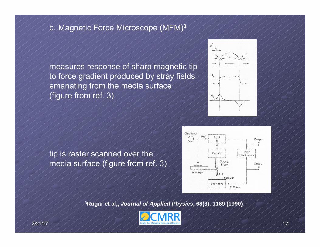
b. Magnetic Force Microscope (MFM)3
measures response of sharp magnetic tip to force gradient produced by stray fieldsemanating from the media surface (figure from ref. 3)
tip is raster scanned over themedia surface (figure from ref. 3)
3Rugar et al,, Journal of Applied Physics, 68(3), 1169 (1990)
13138/21/078/21/07
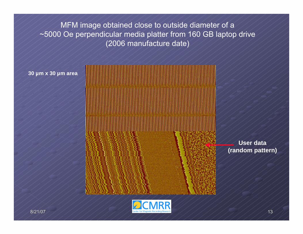
MFM image obtained close to outside diameter of a ~5000 Oe perpendicular media platter from 160 GB laptop drive
(2006 manufacture date)
User data(random pattern)
30 µm x 30 µm area

14148/21/078/21/07
SMRM image of a 20 MHz pattern on ~2700 Oe longitudinal disk media obtained with a 1.5 µm AMR sensor (after exposure to 2080 Oe peak field in a pulsed field
degausser)
0 5 10 15 20 25 30 350.4072
0.4074
0.4076
0.4078
0.4080
0.4082
Play
back
Vol
tage
(V)
Downtrack (µm)
Down-track line scanof MR output voltage
0.0 0.2 0.4 0.60.0000
0.0001
0.0002
0.0003
0.0004
Spatial FrequencyFF
T A
mpl
itude
FFT of down-trackline scan
16 µm
36µm
c. Rigid Disk Test Media
Specimens having a known, saturated, regular magnetic pattern are required for monitoring erasure to the medium noise floor.
15158/21/078/21/07
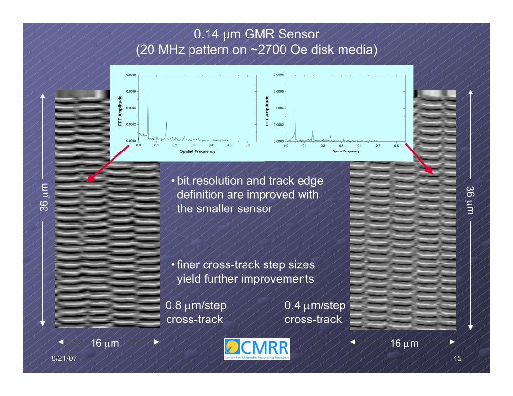
0.14 µm GMR Sensor(20 MHz pattern on ~2700 Oe disk media)
16 µm
36 µ
m
16 µm
36 µm
0.8 µm/stepcross-track
0.4 µm/stepcross-track
0.0 0.1 0.2 0.3 0.4 0.5 0.60.0000
0.0002
0.0004
0.0006
0.0008
Spatial Frequency
FFT
Am
plitu
de
0.0 0.1 0.2 0.3 0.4 0.5 0.60.0000
0.0002
0.0004
0.0006
0.0008
Spatial Frequency
FFT
Am
plitu
de
• bit resolution and track edge definition are improved with the smaller sensor
• finer cross-track step sizes yield further improvements

16168/21/078/21/07
line scan FFT of line scanOriginal Pattern
Partial Erase
0 2000 4000 6000 8000 100000.1170
0.1172
0.1174
0.1176
0.1178
0.1180
0.1182
0.1184
0.1186
Play
back
Am
plitu
de (m
V)
Downtrack (nm)0.0 0.1 0.2 0.3 0.4 0.5
0.00000
0.00005
0.00010
0.00015
0.00020
0.00025
0.00030
Spatial Frequency
FFT
Ampl
itude
0 2000 4000 6000 8000 10000
0.1305
0.1306
0.1307
0.1308
0.1309
0.1310
0.1311
0.1312
0.1313
0.1314
Play
back
Am
plitu
de (m
V)
Downtrack (nm)
0.0 0.1 0.2 0.3 0.4 0.50.00000
0.00005
0.00010
0.00015
0.00020
0.00025
0.00030
FFT
Ampl
itude
Spatial Frequency
Down-track alignment of the MR sensor can be problematic with the SMRM

17178/21/078/21/07
Definition of the “down-track” direction becomes somewhat arbitrary after exposing media with a constant frequency pattern in isolated tracks to large degaussing fields… the selected line scan may actually cross several tracks.
line scan FFT of line scan
0 2000 4000 6000 8000 10000
0.1182
0.1183
0.1184
0.1185
0.1186
0.1187
Play
back
Am
plitd
ue (m
V)
Downtrack (nm)0.0 0.1 0.2 0.3 0.4 0.5
0.00000
0.00005
0.00010
0.00015
0.00020
0.00025
0.00030
FFT
Ampl
itude
This problem is not encountered with preamble-type magnetic patterns…

18188/21/078/21/07
Down-track alignment is less critical with specimens having a preamble-type pattern over the entire disk surface
Isolated tracks (72.5 MHz @ 7200 RPM)
radius = 25 mm radius = 42 mm
“Stitched” adjacent tracks (65 MHz @ 7200 RPM)
24 µm
1.25 µm0.03 µm down-track steps0.05 µm cross-track steps
radius = 25 mm radius = 42 mm

19198/21/078/21/07
MFM phase images of a preamble-like magnetic patternrecorded on ~5000 Oe perpendicular disk media
10mmfrom
disk i.d.
15mmfrom
disk i.d.
20 mmfrom
disk i.d.
25 mmfrom
disk i.d.

20208/21/078/21/07
d. Rigid Disk Erasure Experiment
Production media with highest available coercivity (Hc~5000- 5300 Oe) and having pre-recorded saturated patterns of known frequency (65-90 MHz) are placed in a drive body at the normal platter positions.
Reassembled drives with all original components are placed in the degausser chamber and subjected to either incomplete or complete degauss cycles.
FFT amplitude of the MR playback response, and 2 dimensional power spectral density plots of the MFM images are compared with thoseproduced by the original saturated pattern.

21218/21/078/21/07
SMRM and MFM images are obtained at severaldifferent radii on each test specimen
Inside Radius
Outside RadiusDisk Fragment
24 µm
1.25µm
22228/21/078/21/07
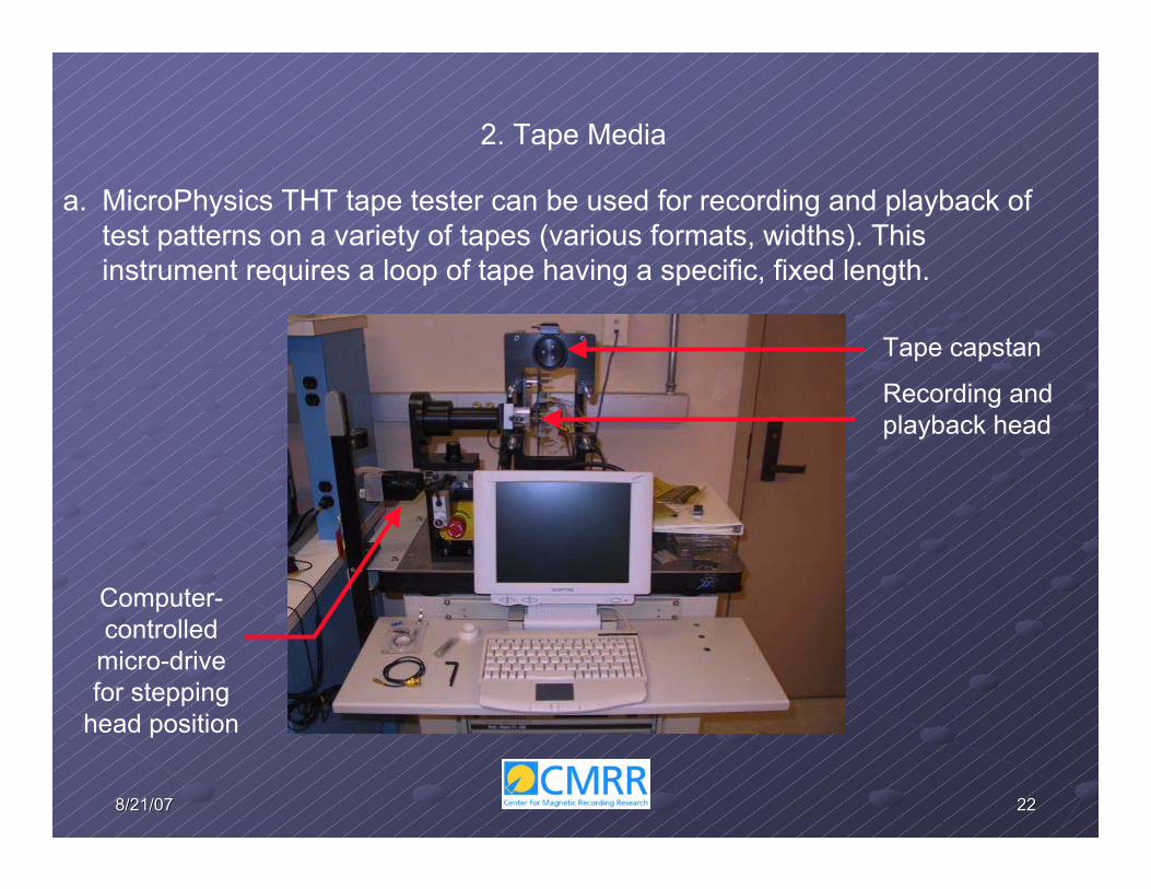
2. Tape Media
Tape capstan
Recording and playback head
a. MicroPhysics THT tape tester can be used for recording and playback of test patterns on a variety of tapes (various formats, widths). This instrument requires a loop of tape having a specific, fixed length.
Computer-controlled
micro-drive for stepping
head position
23238/21/078/21/07
0 2 4 6 8 10
-60
-50
-40
-30
-20
-10
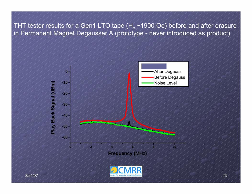
0For PM2000
After Degauss Before Degauss Noise Level
Play
Bac
k Si
gnal
(dB
m)
Frequency (MHz)
THT tester results for a Gen1 LTO tape (Hc ~1900 Oe) before and after erasure in Permanent Magnet Degausser A (prototype - never introduced as product)
24248/21/078/21/07
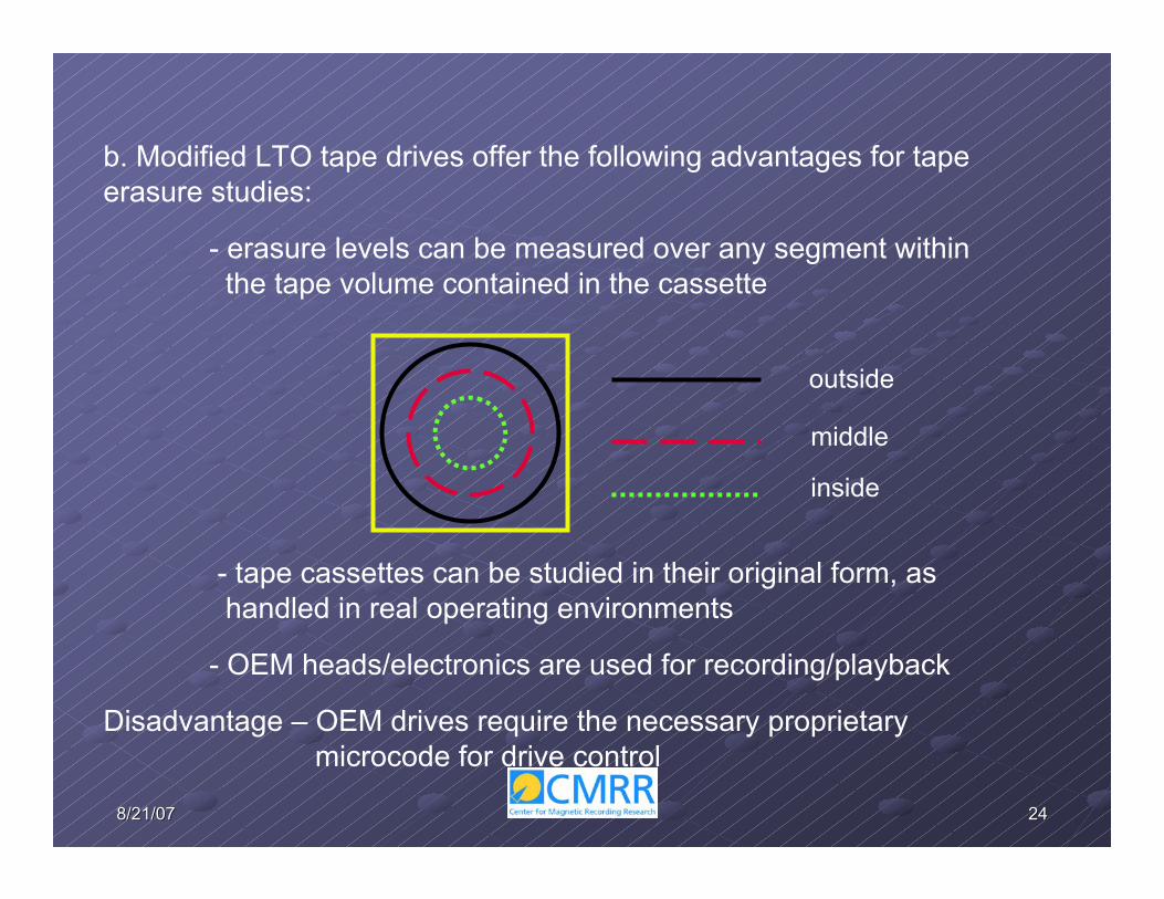
b. Modified LTO tape drives offer the following advantages for tape erasure studies:
- erasure levels can be measured over any segment within the tape volume contained in the cassette
- tape cassettes can be studied in their original form, as handled in real operating environments
- OEM heads/electronics are used for recording/playback
Disadvantage – OEM drives require the necessary proprietary microcode for drive control
outside
middle
inside

25258/21/078/21/07
LTO Gen 1 drive with disabled servo control and tape edge guiding was previously used for erasure studies of LTO Ultrium I (~1900 Oe ) and Ultrium II (~ 2200 Oe) tape media.
Edge guiding is no longer possible with the smaller recorded track widths and “shingle writing” used in Gen 3 and Gen 4 drives (media Hc ~2600-2800 Oe).
Alternative approach: with disabled servo control, monitor erasure of the tape media’s factory-recorded servo patterns using the servo readers in the OEM recording head.Ferrofluid images of one servo band and a portion of one data band in LTO I (left) and LTO III (right) tapes4
4 Images courtesy of IBM Corp.
Servo pattern
Data band
Human hair

26268/21/078/21/07
1
2
The servo reader in LTO drive’s recording head can be locked in the center of a chosen servo band by adjusting the timing between the 4-4 and 4-5 servo bursts before disabling the servo control. This permits erasure to be monitored across tape width.
Servo bands
Head Positions
27278/21/078/21/07
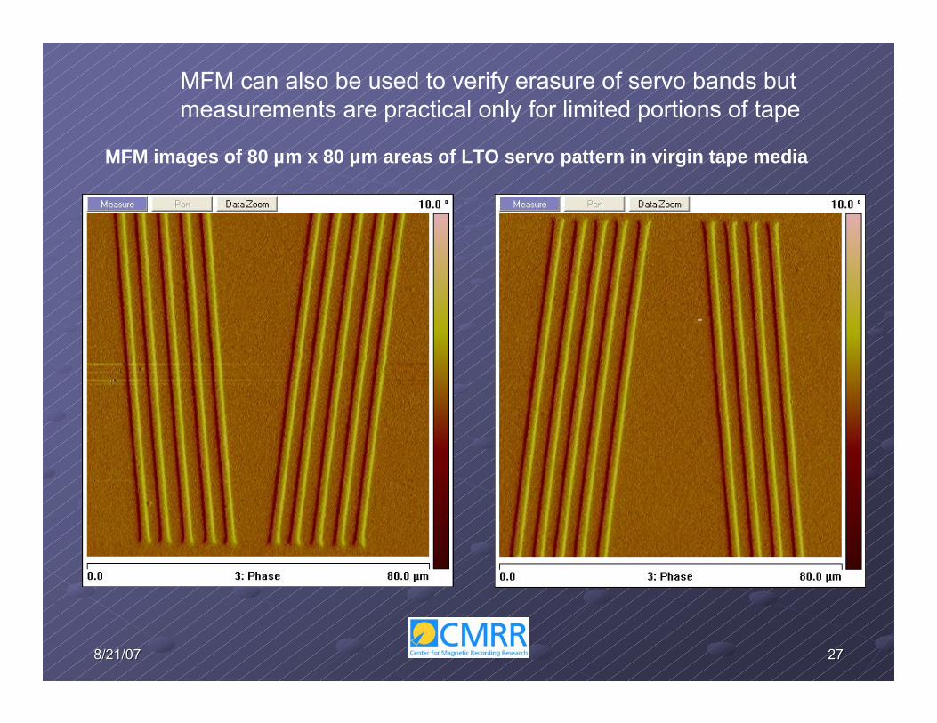
MFM can also be used to verify erasure of servo bands but measurements are practical only for limited portions of tape
MFM images of 80 µm x 80 µm areas of LTO servo pattern in virgin tape media

28288/21/078/21/07
III. Verification of Degausser Efficacy(Rigid Disk Media)
A rotating, decaying field within a plane parallel to the degausser chamber floor results from vector addition of out-of-phase magnetic fields produced by precisely timed high
current discharges through two orthogonal coil assemblies.
0 20 40
-8000
-6000
-4000
-2000
0
2000
4000
6000
8000
Mag
netic
Fie
ld (O
e)
Time (ms)
X-Field (parallel to cavity height) Y-Field (parallel to cavity width) Z-Field (parallel to cavity depth)
Degausser B
Note axis label convention
1. Pulsed Field Degaussers

29298/21/078/21/07
Stress tests show that the peak field magnitudes and the decay profiles of both the Y- and Z- magnetic field components in Degausser B are essentially
unchanged after ~23 hours of continuous, repetitive operation

30308/21/078/21/07
X-Field(height direction)
Y–Field(width direction)
Z–Field(depth direction)
Peak field distributions on a horizontal plane 0.75” above the chamber floor of “Degausser B” (approximate platter position in degausser cavity)
Rear of Chamber
Door Figure aspect ratios intentionally distorted
Gauss
31318/21/078/21/07
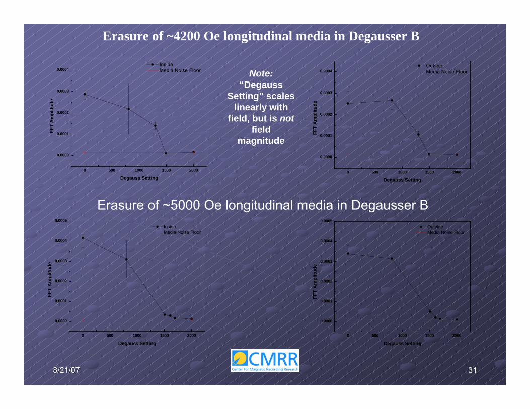
Erasure of ~4200 Oe longitudinal media in Degausser B
0 500 1000 1500 2000
0.0000
0.0001
0.0002
0.0003
0.0004
FF
T A
mpl
itude
Degauss Setting
Inside Media Noise Floor
0 500 1000 1500 2000
0.0000
0.0001
0.0002
0.0003
0.0004
FFT
Am
plitu
de
Degauss Setting
Outside Media Noise Floor
0 500 1000 1500 2000
0.0000
0.0001
0.0002
0.0003
0.0004
0.0005 Inside Media Noise Floor
FFT
Am
plitu
de
Degauss Setting0 500 1000 1500 2000
0.0000
0.0001
0.0002
0.0003
0.0004
0.0005 Outside Media Noise Floor
FFT
Am
plitu
de
Degauss Setting
Erasure of ~5000 Oe longitudinal media in Degausser B
Note:“Degauss
Setting” scales linearly with
field, but is notfield
magnitude

32328/21/078/21/07
0
30
60
90
120
150
180
210
240
270
300
330
02000400060008000
10000120001400016000
02000400060008000
10000120001400016000
Initial Post Stress
Mag
netic
Fie
ld (G
auss
)Polar Plot
For certain critical applications, complete erasure must be achieved well below the peak degausser output (e.g., the pre-recorded pattern on ~5000 Oe media was still recognizable at 75% peak output of “Degausser B”).
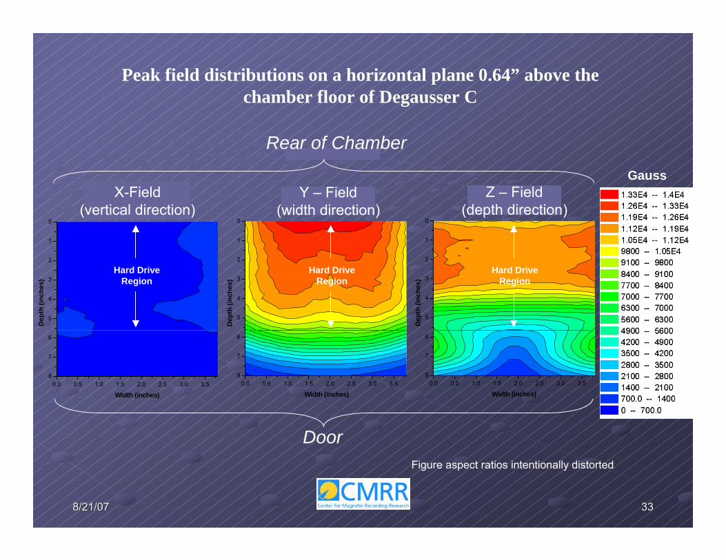
Higher peak fields produced by “Degausser C” provide a greater safety margin for ensuring erasure of sensitive data on ~5000 Oe longitudinal media:
33338/21/078/21/07
0.0 0.5 1.0 1.5 2.0 2.5 3.0 3.58
7
6
5
4
3
2
1
0
Width (inches)
Dep
th (i
nche
s)
0.0 0.5 1.0 1.5 2.0 2.5 3.0 3.58
7
6
5
4
3
2
1
0
Width (inches)
Dep
th (i
nche
s)
0.0 0.5 1.0 1.5 2.0 2.5 3.0 3.58
7
6
5
4
3
2
1
0
Width (inches)
Dep
th (i
nche
s)
X-Field(vertical direction)
Y – Field(width direction)
Z – Field(depth direction)
Rear of Chamber
Door
Peak field distributions on a horizontal plane 0.64” above the chamber floor of Degausser C
Figure aspect ratios intentionally distorted
Gauss
Hard DriveRegion
Hard DriveRegion
Hard DriveRegion
34348/21/078/21/07
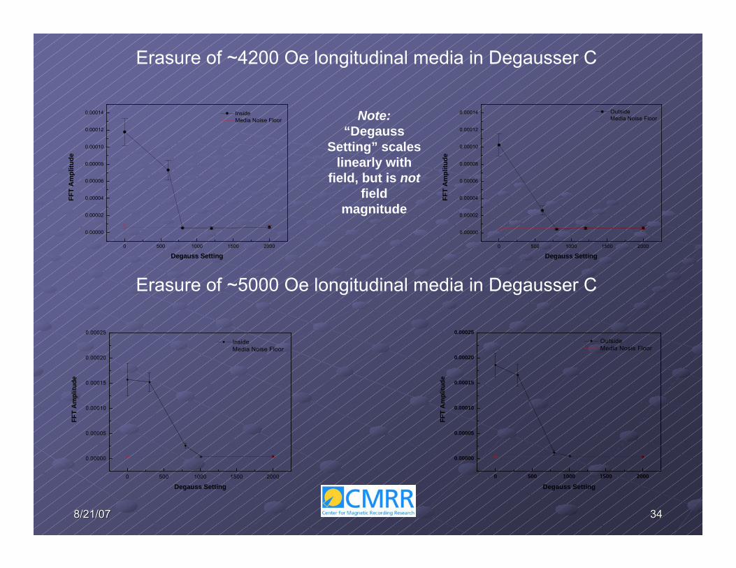
Erasure of ~4200 Oe longitudinal media in Degausser C
0 500 1000 1500 2000
0.00000
0.00002
0.00004
0.00006
0.00008
0.00010
0.00012
0.00014 Inside Media Noise Floor
FFT
Am
plitu
de
Degauss Setting0 500 1000 1500 2000
0.00000
0.00002
0.00004
0.00006
0.00008
0.00010
0.00012
0.00014 Outside Media Noise Floor
FFT
Am
plitu
de
Degauss Setting
Erasure of ~5000 Oe longitudinal media in Degausser C
0 500 1000 1500 2000
0.00000
0.00005
0.00010
0.00015
0.00020
0.00025
Inside Media Noise Floor
FFT
Am
plitu
de
Degauss Setting0 500 1000 1500 2000
0.00000
0.00005
0.00010
0.00015
0.00020
0.00025 Outside Media Nosie Floor
FFT
Am
plitu
de
Degauss Setting
Note:“Degauss
Setting” scales linearly with
field, but is notfield
magnitude

35358/21/078/21/070 500 1000 1500 2000
0.00000
0.00005
0.00010
0.00015
0.00020
0.00025 Outside Media Nosie Floor
FFT
Am
plitu
de
Degauss Setting
The SMRM and MFM produce similar results

36368/21/078/21/07
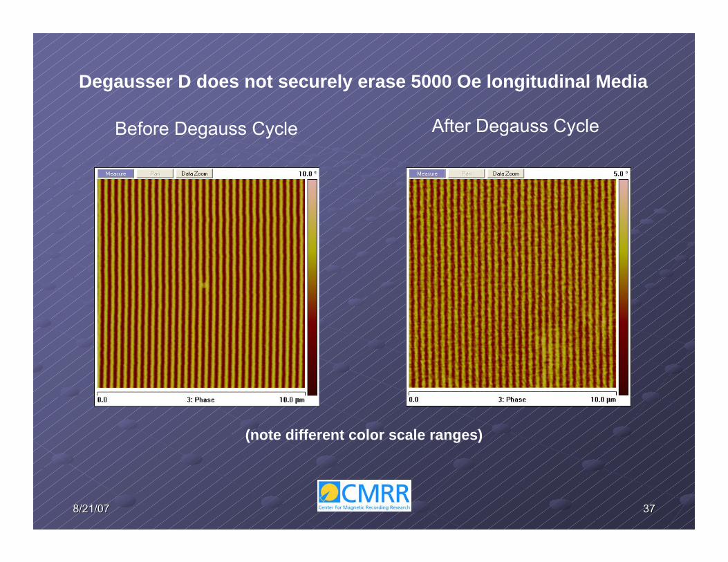
Pulsed Field Degausser D
This degausser employs only one solenoid coil and produces a single field pulse parallel to depth direction (Z-Field). A small permanent magnet assembly
is located near the front of the degaussing chamber.
37378/21/078/21/07
Degausser D does not securely erase 5000 Oe longitudinal Media
Before Degauss Cycle After Degauss Cycle
(note different color scale ranges)

38388/21/078/21/07
0 1 2 3 4 5 6 7 8 9 10 110.0
0.5
1.0
0 1 2 3 4 5 6 7 8 9 10 11
3500
4000
4500
5000
5500
6000
6500
7000
7500
Z-Field Magnitude at 0.67" above Bottom Tray
Z Fi
eld
Mag
nitu
de (G
auss
)
Width (inches)
Hard Drive Region
Other MediaRegion
Gau
ss
Width (inches)Hei
ght (
inch
es)
0450900135018002250270031503600405045004950540058506300675072007650810085509000
0 1 2 3 4 5 6 7 8 90.00.51.0
0 1 2 3 4 5 6 7 8 96500
7000
7500
8000
8500
9000
9500
10000Z-Field Magnitude at .772" above Bottom Magnet
Z Fi
eld
Mag
nitu
de (G
auss
)
Width (inches)
Hard Drive Region
Magnet Frame
Magnet
Gau
ss
Width (inches)Hei
ght (
inch
es)
0650130019502600325039004550520058506500715078008450910097501040011050117001235013000
0 1 2 3 4 5 6 7 80.00.51.01.52.0
0 1 2 3 4 5 6 7 8
10600
10800
11000
11200
11400
11600
11800
12000
12200
Z-Field Magnitude at 0.656" above Bottom Tray
Z Fi
eld
Mag
nitu
de (G
auss
)
Width (inches)
Hard Drive Region
Gau
ssWidth (inches)H
eigh
t (in
ches
)
101001022310345104681059010713108351095811080112031132511448115701169311815119381206012183123051242812550
0 1 2 3 4 5 6 7 8 9 10 11 120.00.51.0
0 2 4 6 8 10 12
4000
5000
6000
7000
8000
9000
10000
11000
12000
Width (inches)
Z Fi
eld
Mag
nitu
de (G
auss
)
Z-Field Magnitude at .62" above Bottom Magnet
Gau
ss
Width (inches)
Hei
ght (
inch
es)
060012001800240030003600420048005400600066007200780084009000960010200108001140012000
Left-to-Right Field Distribution Within Vertical Plane Through Maximum Field Locationin Various Prototype and Production Permanent Magnet Assemblies
Deg
auss
erE
Deg
auss
erF
Deg
auss
erG
Deg
auss
erH
2. Permanent Magnet Degaussers

39398/21/078/21/07
0 1 2 3 4 5 6 7 80.00.10.20.30.40.50.60.70.80.91.0
0 1 2 3 4 5 6 7 8 9
-8000
-6000
-4000
-2000
0
2000
4000
Z-Fi
eld
Mag
nitu
de (G
auss
)
Cavity Depth (Inches)
Z-Field Magnitude at 0.67" above Bottom Tray
Cavity Depth (Inches)
Cav
ity H
eigh
t (In
ches
)
Gau
ss
Front Panel
Front-to-Back Variation of Field Along the Center Width of Degausser E(field polarities are inverted in this figure)

40408/21/078/21/07
Many Degaussers Do Not Meet the Secure Erasure Criterionfor Modern Magnetic Media
MFM comparison of actual data tracks in operating drives (longitudinal media) before and after degaussing in an undisclosed degausser
Media From Reference Drive(not degaussed) Media From Degaussed Drive

41418/21/078/21/07
Ray Descoteaux, Senior Electronic Technician
Jung-Il Hong, Post-Doctoral Researcher/Project SpecialistYun Jun Tang, Project Scientist
Peter Lee, (B.S., Electrical Engineering, graduated)Brendan O’Shea, (B.S., Engineering Physics, graduated)Hamid Toolloei, (Computer Science & Engineering, M.S., graduated)Peter Shchupak, (Electrical Engineering, M.S., graduated)
Jordan Gosselin, undergraduate student (Physics)Lynn Greiner, undergraduate student (Electrical Engineering)Bryan Lettner, undergraduate student (Physics)
ACKNOWLEDGEMENTS